
Document 354857
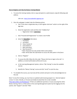
L. T. TROLANILJ. A. BALL, AND J. M. ANDREWS.
r
.
LIQUiD TREATMENT OF CINEMATOGRAPHIC FILMS.
APPLICATION FILED SEPT. 1. 1921.
1,435,76é2.
Patented
M, 1922.
2 SHEETS-SHEET I.
71v677f0r
W
jeomfd
12
)
,s;
L. T. TROLAND, J. A. BALL, AND J. M. ANDREWS.~~
LIQUID TREATMENT OF CINEMATOGRAPHIC FILMS.
APPLICATION FILED SEPT. l. 1921.
1,435,764.
Patented NOV. 14, 1922.
2 SHEETS—-—SHEET 2.
'
_
157067771074
b€0na7t57T
103827;” '
9mg;
745.325’.
%
.
7. S1‘
1,435,764
ltd, 1922.
.
A
‘is:
D STATES PATENT OFFICE.
‘2?. 'I‘ROLAND, OF MALDEN, AND JOSEPH A. BALL AND JARVIS M. ANDREWS,
TQLLASTON, MASSACHUSETTS, ASSIGNORS TO KALMUS, COM‘STOCK & WESCOTT,
J., OF BOSTON, MASSACHUSETTS, A CORPORATION OF MASSACHUSETTS.
LIIQUID TREATMENT OF CINEMATOGRAPHIC FILMS.
Application ?led September 1, 1921. Serial No. 497,590.
surface tension, we have discovered that it
iii met may concern:
. sown that we, LEONARD T. Tno
is not only possible but highly practicable.
In one aspect the invention involves main 65
.i. BALL, and JARvrs M. AN
of the United States of tainingr the ?lm substantially flat and there
restraining it from contacting with the
zston, Massachusetts, respec liquid on its upper side and, where the ?lm
counties of Middlesex, Nor-' iis supported by floating, preventing it from
‘elk, respectively, and State of sinking, by making the ?lm multi-ply. For
.esidents of Maiden, Wollas
10
~ ‘, have invented new and use
vaphic Films, of which the fol
LLA
in
15
60
example, if two ?lms are properly secured
oveiients in Liquid Treatment of together back-to-back with the coatings on
‘
eci?cation.
oion relates to the liquid treat
the outer sides, the resulting double ?lm will
have less tendency to curl and buckle, even
when only one side is wet, presumably for
65
photographic ?lms, particularly the same reason that a multi-ply board or
w
ic ?lms, and speci?cally to cardboard has less tendency to Warp and
'o
one
In
curl than a single ply 'piece.
In another aspect the invention consists
in making the film water-repellent at the
70
or pictures representing one sides, preferably from the extreme edges
20
‘ are carried on one side of the
‘ iemental series representing
inwardly to lines extending longitudinally
of'the ?lm slightly inside the sprocket holes.
aspect is carried on the other One way of rendering the marginal portions
of the ?lm water-repellent is to make the 75
celluloid support bare and clean throughout
iii’erently as, for example, by such portions. This is preferably accom~
' L, it is frequently desirable to
'iosite sides of the ?lm sepa
25
de a reddish color and the
plished by dissolving off the unexposed gela
tine emulsion and thoroughly washing the
of the invention is to provide ?lm, thus leaving the celluloid perfectly 80
no. apparatus for treating one bare and clean outside the lateral edges of
n independently of the other side the images which are slightly inside the
rows-of sprocket holes. The unexposed por
tions may be dissolved off without affecting
_ at oi" the ?lm. Another object is to the images ‘between the rows of sprocket
‘iCli'Z-y and uniformity, without in
' e ?lm, and without affecting the
85
a, method and means for automati~ holes by ?rst hardening the gelatine
‘ ,ring a ?lm to normal position in throughout the exposed image spaces in
‘ at the ?lm tends to submerge on. known manner. The marginal portions of
'
e result of a wavy edge such as
have.
.
vo the present invention the
sad along the surface of a body of
such manner that it is supported
the ?lm may be rendered even more liquid
repellent by a coating which is not readily
acid wax.
,
'
In order to illustrate the invention, one
Y the iiquid without the aid or" any concrete embodiment is shown in the accom
7 supports, thereby avoiding the
maintaining the liquid at a de?
45
panying drawings, in which,—~
has heretofore been considered
c and other photographic ?lms,
- the liquid has a relatively low
95
Fig. 1 is a side elevation of a complete.
nits predetermined level relatively to the machine;
Fig. ‘2 is a section on the line 2-2 of
supports and also avoiding friction and
' of ‘the ?lm by the supports. Fig. 1:
in the case of the thin and tenu
such as are used in treating cine
90
wet by aqueous solutions, such as stearic
Fig. 3 is a plan, viewed from line 3-3 of 100
Fig. l of a portion of the drying chamber
showing the drying-air feed-pipe incross
section;
v.
‘
‘
F ig.4 is an enlarged sectional view ofthe
wear/ea
La
liquid trough, showing a ?lm ?oating upon may be supportedat intervals upon legs, or 68
the surface of the liquid within the trough; as shown in Fig. 4 it may be stamped from '
10
15
Fig. 5 is a view similar to Fig. 4 showing a single sheet of metal. At one end of the
the action of the ?lm and the liquid when troughs 23 and 24 are the triangular sup
ports 26, one being located upon each side of
the former becomes displaced;
Fig. 6 is a longitudinal sectional view of the troughs as shown in enlarged scale in
the liquid trough and general assembly of Fig. 6. These~ triangular supports are con
the lower portion of the apparatus, the cen nected together by a rod 27 upon which is
tral portion of the trough being cut away; mounted guide roller 28 similar in construc
Fig. 7 is a detail section of line 7—~7 of tion'to guide rollers 16. At the apex of the
Fig. 6, showing surface liquid removing triangular support are registering holes 29
serving as bearings for a shaft 30 forming
means;
Fig. 8 is a sectional view on the line 8-8 a portion of the carriage 31 which comprises
of Fig. 1, showing in elevation the means side arms 32 connected by rods 33 upon
'for drawing the ?lm through the machine; which are rollers 34 and 35. In'order to
Fig. 9 is a sectional view on the line‘ 9—~9 hold the carriage 31 in adjusted position the
of Fig. 6, showing. in elevation the devices triangular supports are provided with bind
70
75
80
for applying the liquid repelling substance ing screws acting upon the shaft 30.
20
At the opposite end of the treatment tank
to the edges of the ?lm;
Fig. 10 is a detail vertical sectionalyiew are brackets 36 extending upwardly from
through one ofthe devices shown in Fig. 9; the base 11. These brackets are connected
and
'
_ Fig. 11 is an enlarged cross section of a
85
by rods 37 and 38 upon which are mounted
respectively plain roller 39 and guide roller
?lm such as above described (in which S 40.
25
Supported between rods 37 and 38 by
and S’ are the two celluloid strips cemented means of attachment members 41 is a block
together and R and R’ are the images car 42 shown in detail in Figs. 6 and'7. This 99
ried by the respective strips).
bloci: acts as a means for removing the
iiquid from the ?lm as the latter is-'
The speci?c embodiment ofthe invention
30
chosen for purpose of illustration comprises
a-base 11 to which are fastened U-shaped
supporting uprights 12 connected by eros'
members 13. These upright and cross
'
bers are preferably made in one ‘1319i
Upon the cross members 13 is supported an
35
40
elongated drying chamber 14 enclosed on
the top, bottom and sides and open at the
ends. Within the drying chamber and
mounted in U-shaped supports 15 are rollers
shoulders
16 consisting
18 ofof greater
a central
diameter
drum 17
.ian the
drum and beyond these guide ?anges 19 of
still greater diameter. When the rim is fed
rem the treatment trough. The means
removing the excess liquid comprises
-_“-"isve1‘se nozzle 43 fast at the lower por 95
tion.
the block and allowing space through
in the block for the passage of the
ted ?lm above the nozzle. The nozzle
s
elongated slot 44 directed at an angle
of approximately 45° toward the ?lm as 100
issues from the treatment trough. A pipe
connects the nozzle with any suitable
source of compressed air. The portion of
the block 42 directly above the ?lm has a
hollow‘ chamber 46 shown in Fig. 7 with
openings into the recess in which the ?lm
through the drying chamber after the liquid travels directly above the sprocket holes in
treatment the edges of the film restv upon the the ?lm. Threaded into the chamber 46 is
105
a pipe 47 to which there is a connection
?lm cannot contact with the drum 17. At from a suction pump. The blast of air from
one end of the drying chamber is pipe 20 the slot in the nozzle below the block coop
through which warm air is forced into the erates with the suction means above the ?lm
drying chamber through the side opening .1. to completely remove all liquid from the
113
45 shoulders 18 so that the moist face of the
50
sprocket holes of the ?lm, and also sweep
is Supported
a broad U~shaped
upon the trough
base 11 23
by shown
biocirs in the lower portion of the ?lm which has been 115
cross-section in Fig.2. Within the trough treated clear of surface‘liquid.
Mechanism of the general character above
23 is mounted the elongate shallow trough
24 for the liquid treatment of the ?lm (Fig. described for removing surface liquid from
55 4).
The trough 23 serves as a means for a ?lm is claimed in the application of Daniel
taking care of accidental ‘over?ow from F- Comstock, Serial No. 497,703 ?led on even 120
trough 24, pipe 23’ (Fig. 6) being‘ arranged date herewith.
to carry away this over?ow. The trough 24
Suitable means for applying a liquid re
has upwardly ?aring or diverging sides 25 pelling substance to the edges of the ?lm
60
which extend above the level at which the are shown in detail in Figs. 9 and 10. The
liquid is constantly maintained. The dis substance applied by this device is stearic
tance between the sides 25 at the level of acid wax, although other substances. e. g.
the liquid is slightly greater than the width para??n. may be used. Removably clamped.
of the ?lm A to‘ be treated. The trough24 to the side arms 32 of the carriage 31 by
125
'
1 $35,704.
‘
of set screws 48 are bracket arms 49
of the liquid,threaded upwardly under roller
‘ g inwardly and over the edges of 39 through the recess in the surface liquid re
in‘ proximity to roll 34. The outer moving block 42 under guide roller 40, up
bracket arms 49 support tubes 50 through a slot in the drying chamber 14 over
.
ng pistons 51 urged downwardly by the guide rollers 16, throughout the length
sp 'ngs' 5:2, the tension of the latter being of the drying chamber over the sprocket
70
it by hand screws 53. A stick of wax wheels 57, the sprocket teeth being regis
olaccd in‘ the lower end of the tube 50 tered in the sprocket holes of the ?hn, and
and ed in frictional contact with the edges down around an empty ?lm reel upon the
10" of the ‘film by the spring-pressed piston 51. extremity of shaft 69, the takeup reel being
'
,ilication of Wax' or the like is par driven by a belt (not shown) over pulleys
_
L, ‘desirable prior to treating the 65——71 or 66-—72. Since it is impossible to
second'side of a ?lm as the tendency for arrange for the slight variation in proportion
the‘, PM id’to flow over the top is sometimes between the speeds of shafts 57 and 69 in
if the upper surface has already reeling up the ?lm, a provision is made for
161 I
slip” between the driven member 70 and
right-‘hand end of the device as. shaft 69, comprising'arrangin the driven
~ in Fig. 1, and supported above the member 70 loosely upon sha t 69- but in
'
ted.‘
' “i l’ hymeinbcrs
similar to supports 12,
so’;vi
spring-pressed frictional engagement with
his 56 iipon which is mounted thel the collar'73.
20'"
75"
as
‘ drawing the ?lm through the _ A cardinal feature of the invention con
machi- . This means is shown in detail in sists in the upwardly ?aring sides of the
F
6 and comprises a main shaft 57 sup liquid trough and the slight clearance be
in bearings 59 and provided with tween the edges of the ?lm and the sides of
t wheels 58 which cooperate with the the trough when the film is ?oating nor 90 '.
t holes on the- sides of the ?lm. mally. If the liquid creeps over the edge of
25
.,
57 has keyed upon its central por
the ?lm, as a result of curling or buckling,
thereby submerging one side of the ?lm, the
upon a shaft '62 mounted transversely submerged edge engages the inclined, side
' 57' and below the same. Shaft 62 and by virtue of the inclination the other
n through pulley wheel_63 from any side is caused to ride up the opposite inclined
iie source of power. Upon the end of side, the ?lm assuming aposition such as
T opposite to the .end of the sprocket shown in Fig. 5. Owing to the surface ten
wheels, ‘is the driving member 64 comprising sion acting on the tipped-up side the ?lm is
a
pulley wheel 65 and a smaller pulley either restored to normal position or re
wheel 66. , Suspended below table 56 is a strained from being submerged except inthe
bracket support 67 having an elongated immediate region of the curl or buckle.
In forming the relief images the mar
bearing68 for a shaft 69 arranged in paral
lei relation to shaft 57. Shaft 69 has a ginal portions of the gelatine or other col
a. worm gear 60 meshing with a worm
projecting end directly below sprocket loid material are completely removed in the.
57 over which a ?lm reel is adapted hot-water etching bath, the! marginal por
to be placed, upon which ‘the ?lm, after tions being unexposed. Thus the gelatine
109.
105
being treated and dried, is adapted to be or other colloid material in which the im
wound. In order to turn the drum at a. ages are formed terminate short of the mar
.15 proper speed to take up the ?lm, the op ginal edges of the ?lm and indeed is con?ned
posits end of shaft 69 is provided with to the space between the series of marginal
‘ driven member 70 comprising smaller pulley registering openings (Figs. 3 and 4). This is'
wheel 71 directly below pulley wheel 65 and important in coloring the relief images inas
pulley “.72 directly below‘ pulley 66. Driven much as pigment solution can be applied to
56 member 70 is loose upon shaft 69 but is one side with little or no tendency to creep 115
held hy springs 74 in frictional contact with around the edges of the ?lm to the opposite
dish '73 keyed’ to shaft 69. The tension of side by virtue of bare celluloid margins.
‘
355
'74 is regulated by collar 75 l
‘ position on shaft 69 by so
operation of the device is
l in
, '.
of ?lm is placed upon the bracket
t 77 which is suspended from the base
‘ . ?lm in ‘this reel‘is threaded‘ up
through an opening'in the base 11
“7e claim:
1. The method of treating a roll of’photoé
graphic ?lm which comprises moving the 12!)
?lm over a body of liquid in surface contact
out
therewith
the major
and supporting
part of thatthe
portion
?lm throughl
contact-y - P1
ing with the liquid solely by the liquid. 7
guide roller 27, then upwardly over
2. The method of treating a roll of photo-7 v
under the wax ends 54, over roller graphic ?lm comprising extending a long‘
“ en downward the length of the section of the ?lm along the surface'of a
t trough 24, the film resting upon liquid so that the ?lm is supported solely by
ice of the liquid and being supported, the liquid which wets the lower surface of
'
The ?lm is drawn along the surface. the ?lm only. ,
130
The method of treating a roll of photo
12. The step in the method of treating,
graphic ?lm comprising extending a long photographic ?lms which comprises ?oating
section of the ?lm along the surface of a the same upon a thin and tenuous ?lm-stain-l
liquid so that the ?lm is supported solely ing ?uid.
13. In apparatus for treating photo
by the liquid which wets the lower surface
of the ?lm only and continuously drawing graphic ?lms, a long narrow trough having
‘ ‘i the ?lm ‘forwardly along the surface of the diverging sides and adapted to contain liq
10
uid, guiding means for the ?lm at each end
of the trough whereby a section of the ?lm
may rest within the trough and be support
ing applying a liquid repellent substance to ed by the liquid, means for removing the
the edges of the ?lm and then ?oating the excess liquid from the ?lm as the latter is
sues from the trough comprising ?uid pres—
?lm upon a liquid.
.
i
5. The method of treating ?lms compris sure and ?uid suction means, a drying cham
ingapplying a liquid repellent substance to ber above said trough and means for contin
liquid while the ?lm continues to be sup
ported by the liquid.
_
4c. The method of treating ?lms, compris
70
75
80
the edges of the ?lm, ?oating the ?lm upon uously conducting the ?lm along the trough,
a liquid, and moving the ?lm forward while, past the surface liquid removing means and
through the drying chamber.
so supported by the liquid.
_
14:. ‘n apparatus for treating phot0~
6. The method of treating ?lms compris
ing applying a liquid repellent substance to graphic ?lms, a long narrow ‘trough having 85
the edges 01’ the ?lm, floating the ?lm upon diverging sides and adapted to contain liq
a liquid, moving the ?lm. forward while so uid, guiding means for the ?lm at each end
supported, removing surface liquid from the of: the trough whereby a section of the ?lm
?lm, and then drying the ?lm.
_ may rest within the trough and be supported
by the liquid. means for applying a water 90
7.
The
method
of‘treating
the
lower
su_r~_
25
face of photographic ?lm with a liquld repelling substance to both edges of the ?lm
in suchinanner as to prevent access of the betoreit enters the trough, and means for
liquid to the other side which comprises ap progressively conducting the ?lm under the
plying to theedges of the ?lm a substance applying means and along the trough.
15. In apparatus for treating photo 95.
'30 which will prevent the liquid from wetting
the ?lm and then passing the ?lm along the graphic ?lms, a long narrow trough having
diverging sides and adapted to contain liq
surface of the liquid.
‘ 8. The method of treating the lower sur uid, guiding means for the ?lm at each end
face of a photographic ?lm with a liquid in
the trough whereby a section of the ?lm
such manner as to prevent access of the may rest within the trough and be supported 100
liquid to the other side which comprises ap by the liquid, means for applying a water
plying to the edges of the ?lm a substance repelling substance to both edges of the ?lm
which will prevent the liquid from wetting before it enters the trough, a drying cham
the ?lm and then passing the ?lm along the ber above said trough and means for con-_
surface of the liquid, the ?lm being sup tinuously conducting the ?lm under the ap
ported solely by the liquid.
105
plying ‘means along the trough and through v
‘ 9. The‘ method of preparing an elongate the drying chamber.
16. In ' apparatus for treating photo
Q.
strip of photographic ?lm which comprises
joining a plurality of ?lms together to form graphic ?lms, a long narrow trough having
a multi-ply ?lm, and then passing the ?lm diverging sides and adapted to contain liq.
lengthwise over and in contact with-the sur uid, guiding means for the ?lm at each end
face of a body of liquid, whereby the ?lm is of the trough whereby a vsection of the ?lm
'maintained relatively ?at and is restrained may rest within the trough and be supported
from contacting; with the liquid on its up by the liquid, means for applying a water
Kill per side by virtue of its multi-ply character. repelling substance to both edges of the ?lm
10. The method of preparing an elongate before it enters the trough.
all
strip of photographic ?lm which comprises
lili
"
joining two coated ?lms baclr-to-back to
form a symmetrically double ?lm and float
ing the ?lm lengthwise over and in contact
with the surface of a body of liquid, where
by the ?lm is maintained relatively ?at and
is thereby restrained ‘From contacting with
the liquid on its upper side by virtue of its
symmetrically double character.
ll. The step in the method (it treatingr
110;.»
115
17. In apparatus for treating photo-’
graphic ?lms, a liquid trough having up
wardly diverging sides, the distance between.
said sides at the liquid level being slightly 120
greater than the Width of the ?lm to be
treated, and means for moving the ?lm lon—
gitudinally of the trough.
18. In apparatus for treating photo~
graphic films, a liquid trough having di
125
verging sides, the distance between said ‘sides
mated photographic films which comprises at the level of the liquid being slightly
floating the same upon a thin fluid medium greater than the width of the ?lm, and
capable of changing the color of the coating means for passing the ?lm along the surface
upon the ?lm.
of the liquid in the trough so that the ?lm
130
'
1,435,764
is normally supported solely by the liquid. strip of photographic ?lm having a row of
19. In apparatus for treating rolls of pho images supported on a water-repellent sup
tographic ?lms, a trough adapted to contain port which comprises moving the ?lm
liquid, ?lm guiding means arranged to guide lengthwise over and in contact with the sur
the ?lm to and from the surface of the liq
30
face of a body of liquid with the marginal
uid, and means for applying a liquid repel portions of the ?lm bared. '
ling substance to the edges of the ?lm before
24. The method of‘treating an elongate
it contacts with the liquid, thereby to insure strip of photographic ?lm having a coating
its floating.
10
15
of gelatine or the like on at least one side 35
20. The method of treating ?lms which thereof, said coating terminating short of
comprises rendering the marginal portions the marginal edges of the ?lm, which com
of the ?lm water-repellent and then ?oating prises passing the ?lm over a body of liquid
with the other side in contact with the liquid.
the ?lm upon a ‘liquid.
21. The method of treating photographic
25. The method of treating an elongate
?lm having a coating of gelatine or the like strip of photographic ?lm having a coat
on at least one side, such coating terminating ing of gelatine or the like on at least one
40
short of the marginal ed es of the ?lm side thereof which comprises removing the
which comprises wetting t e other side 0 coating from the marginal portions of the
?lm and then passing the ?lm over a body 45
the ?lm.
22. The method of treating photographic of liquid with the other side in contact with
20
'
'
?lm having a coating of gelatine or the like the liquid.
on at least one side which comprises remov
Signed by us at Boston, Massachusetts,
ing the coating from the marginal portions this 30th day of August, 1921.
of the ?lm and then wetting the other side
of the ?lm.
.
23. The method of treating an elongate
LEONARD T. TROLAND.
JOSEPH A. BALL.
JARVIS M. ANDREWS.


© Copyright 2026