
EXSULITE FACADE SYSTEMS CONSTRUCTION DRAWINGS
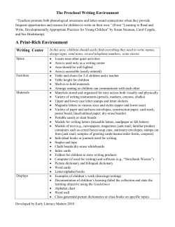
EXSULITE FACADE SYSTEMS
®
CONSTRUCTION
DRAWINGS
AUSTRALIA · 01 OCTOBER 2014
VERSION 1
EXSULITE
®
Overview1
Slab Edge Overhang 4
CONSTRUCTION
DRAWINGS
Exposed Edge Slab Rebate
5
Parapet Wall Construction To Box Gutter
6
Metal Capping Parapet
7
THE SOLUTION TO
LIGHTWEIGHT WALL
CLADDING SYSTEMS.
Balustrade Wall Construction
8
Waterproofing9
Masonry Junction Detail
10
Double Stud Panel Junction
11
Panel To Masonry Metal Flashing
12
Flush Panel To Masonry Sealed Joint
13
Horizontal Expansion Joint Detail
With Expansion Trim
14
Vertical Expansion Joint Detail
With Expansion Trim
15
Internal Corner Junction
16
External Corner Junction
17
Window Head And Sill
18
Window19
This manual is provided as a source of information
and is only intended for guidance. It cannot fulfil
the functions of a professional, engineering or
design consultancy. Professional advice should be
sought to determine the suitability of this product for
the intended end use. The use of sound building
practices should always be applied and this
manual may not contain all the necessary relevant
information. Please seek professional advice on all
aspects of design, engineering and installation.
This manual is to be treated as one document, do
not separate and distribute individual pages.
Please visit exsulite.com.au for the most current
Specification and Installation Manual and
Construction Drawings.
II
Timber Window Detail
20
Roof Truss Eaves
21
Flashing Detail To Ridge Capping
90 Degree Starter Channel
22
Flashing Detail To Metal Deck Roof
90 Degree Starter Channel
23
Meter Box Penetration
24
Wall Penetration
25
Down Pipe Fixing Plan
26
External Fixing
27
Overview
Dulux® AcraTex® - is a pioneer in the use of External Insulation Facade Systems (EIFS), designing and installing coating systems
specifically for wall applications. EIFS walling systems have been used in Europe for over 50 years. In recent years the use of
Lightweight Cladding Systems, as alternate solutions in the building and constructions industry has grown rapidly but proper system
design and installation has not been considered.
The Building Code of Australia (BCA) (or National Construction Code (NCC)) requires appropriate design and installation controls to
qualify any alternate solution and ultimate success requires a total system approach integrating design, componentry, installation and
performance requirements.
The Exsulite Facade System by Dulux AcraTex protects specifiers, surveyors, builders and their clients from the risks of mixed componentry
being used with uncontrolled installation. Exsulite Facade System by Dulux AcraTex offers a single supply source for the Total Light
Weight Facade System – from wall wrap to the weatherproofing coating.
The Exsulite Facade System is a light weight exterior walling system that provides both weatherproofing & insulation of the building
envelope and helps to eliminate thermal bridging that can occur through the wall frame.
The Exsulite Facade System is designed as a total integrated non-load bearing lightweight facade system to deliver a
weatherproof external building envelope with a self draining cavity for moisture management whilst providing high thermal
performance (R value). The Exsulite Facade System is CodeMark™ certified as a total integrated facade system for use as either
a cavity or non-cavity system known as:
A) Exsulite Thermal Facade Cavity System B) Exsulite Composite Thermal Facade Cavity System C) Exsulite Thermal Facade Non-Cavity System D) Exsulite Composite Thermal Facade Non-Cavity System The Exsulite Facade System comprises of an Exsulite breathable wall wrap, flashing tape to all openings & penetrations, Exsulite EPS
Panel or Exsulite Pre-Coated Composite Panel, Exsulite starter piece / cavity closer with weep holes, Exsulite fixing components, EPS
“H” Grade wall cavity spacers where a cavity system is selected, Exsulite Matrix Basecoat™ with alkali resistant mesh, Exsulite Texture
and Exsulite Membrane weatherproof protective coating or an approved Dulux AcraTex texture and AcraTex membrane topcoat system
designed & supplied by Dulux AcraTex and installed by a Dulux AcraTex Exsulite Trained & Registered Installer.
Design Considerations
System design should consider factors such as:
• Purpose of structure for Residential or Multi‑Residential
• Thermal (R-Value) – energy efficiency
• Location – coastal or inland
• Bush Fire Attack Levels (BAL)
• Identify BCA performance requirements and any additional
project specific needs
• Acoustics (Rw Ctr values)
• Wind design actions subject to local wind pressures
• Minimum panel thickness based on wind design pressure
• Self draining cavity to allow drainage of any moisture
ingress or condensation
• Colour selection – Light Reflective Value (LRV>35)
• Wall wrap – vapour permeable for condensation control
& weatherproofing
• Control joint installation
• Frame type, layout, design, stud spacing (steel or timber)
• Additional wall insulation to improve energy efficiency
Construction Drawings Version 1 · 01 October 2014
1
Fixing Guide
Exsulite Thermal Facade Cavity System – Residential Housing Vol 2 Class 1 & 10:
Frame
Type
Timber
Metal
Panel
Thickness
Cavity
Spacer
Starter Channel
(weepholes)
Minimum
Screw Length
Class
Gauge
Type
60mm
15mm
75mm
105mm
3
10
Bugle Needle Point
75mm
25mm
100mm
130mm
3
10
Bugle Needle Point
100mm
25mm
125mm
165mm
3
10
Bugle Needle Point
60mm
15mm
75mm
105mm
3
10
Bugle Needle Point for
use up to 0.55mm steel
75mm
25mm
100mm
130mm
3
10
Bugle Needle Point for
use up to 0.55mm steel
100mm
25mm
125mm
150mm
3
10
Bugle Needle Point for
use up to 0.55mm steel
Exsulite Thermal Facade Non Cavity System – Residential Housing Vol 2 Class 1 & 10:
Frame
Type
Timber
Metal
Panel
Thickness
Starter Channel
(weepholes)
Minimum
Screw Length
Screw
Type Class
Gauge
Type
60mm
60mm
105mm
3
10
Bugle Needle Point
75mm
75mm
105mm
3
10
Bugle Needle Point
100mm
100mm
130mm
3
10
Bugle Needle Point
60mm
60mm
105mm
3
10
Bugle Needle Point for
use up to 0.55mm steel
75mm
75mm
105mm
3
10
Bugle Needle Point for
use up to 0.55mm steel
100mm
100mm
130mm
3
10
Bugle Needle Point for
use up to 0.55mm steel
NOTE: Needle point screws used for timber frame fixing applications can be used in light gauge steel frame fixing depending
on the length of the screw, the needle points can pierce through 0.55mm steel. Where heavier gauge steel is used and exceeds
0.55mm a self drilling metal screw is required to be used. Within 1km of a coastal environment Class 4 screws must be used.
This is deemed as medium to severe marine exposure in accordance with AS 3566.
Exsulite fixings Class 3 (non coastal areas) 10 Gauge screws with an Exsulite 40mm fixing disk is driven into the middle of the stud
until the disk just penetrates the panel face. When fastened correctly, the screw head and the 40mm fixing disk should be slightly
countersunk in a concave recess on the outer surface of the panel and located so as it retains its original shape.
NOTE: Care should be taken to not overdrive the fixing as this will strip the plastic disc and the fixing will be ineffective.
General vertical fixing spacings of 275mm (5 fixings at 275mm spacing / 25 per sheet with 50mm end distance at panel corner adds
up to 1200mm panel width) with stud spacings at 600mm maximum and subject to panel span and thickness.
2
Wind Classification
Table One – For Wind Classification to AS4055 Minimum Panel Thickness and Fixings
Wall Areas (Over 1200mm Away From Corners)
Stud Centres 450mm
Wind
Classification
(AS4055)
Stud Centres 600mm
Min Panel
Thickness
Fixings
per stud
Fixing
Spacings
Min Panel
Thickness
Fixings
per stud
Fixing
Spacings
N2
40mm
5
275mm
60mm
5
275mm
N3
60mm
5
275mm
60mm
5
275mm
N4
60mm
5
275mm
75mm
5
275mm
N5
75mm
5
275mm
100mm
5
220mm
Table Two – For Wind Classification to AS4055 Minimum Panel Thickness and Fixings
Walls Located Within 1200mm from Corners
Stud Centres 450mm
Wind
Classification
(AS4055)
Stud Centres 600mm
Min Panel
Thickness
Fixings
per stud
Fixing
Spacings
Min Panel
Thickness
Fixings
per stud
Fixing
Spacings
N2
40mm
5
275mm
60mm
5
275mm
N3
60mm
5
275mm
75mm
6
220mm
N4
60mm
7
180mm
100mm
8
150mm
N5
75mm
8
150mm
100mm
11
110mm
Table Three – AS1170.2 – Wind Pressure Criteria Design For Buildings That Fall Outside AS4055
Maximum fixing spacings to satisfy design ultimate wind pressures (kPa)
Design Ultimate
Wind Pressure
AS1170.2
Stud Centres 450mm
Stud Centres 600mm
Min Panel
Thickness
Min Fixings
per stud
Fixing
Spacings
Min Panel
Thickness
Min Fixings
per stud
Fixing
Spacings
1.0
40mm
5
275mm
60mm
5
275mm
1.5
40mm
5
275mm
60mm
5
275mm
2.0
60mm
5
275mm
60mm
6
220mm
2.5
60mm
6
220mm
75mm
8
150mm
3.0
60mm
7
180mm
75mm
9
130mm
3.5
60mm
8
150mm
100mm
10
120mm
4.0
75mm
9
130mm
100mm
11
110mm
4.5
75mm
10
120mm
-
-
-
5.0
75mm
11
110mm
-
-
-
5.5
75mm
11
110mm
-
-
-
Assumption is based on a panel size of 2500mm x 1200mm panel size. It is acceptable to use a panel thickness equal to or greater
than the minimum requirement to satisfy the wind classification and meet thermal requirements. Increased peak pressures occur near the
edges of side walls and corners on buildings. Using AS4055, the size of the building has been assumed and hence the size of these
high pressure zones is specified as within 1200mm from wall corners.
NOTE: The fixings per stud indicate the number of fixings required at each stud along each sheet.
Construction Drawings Version 1 · 01 October 2014
3
Slab Edge Overhang
EXSULITE® BREATHABLE
ABSORBENT WALL WRAP FIXED TO
STUD FRAMING
WALL INSULATION AS
SPECIFIED
PLASTERBOARD WALL LINING
EXSULITE® CAVITY SPACER FIXED
TO STUD FRAMING
STUD FRAME AT 600MM MAX
CENTRES
EXSULITE® PANEL
SKIRTING
EXSULITE OR ACRATEX® COATING
SYSTEM WITH REINFORCING MESH
SPECIFIED FLOORING
MATERIAL WITH UNDERLAY AS
PER MANUFACTURERS
REQUIREMENTS
WASHER SECURED WITH SCREW AT
275MM MAX. VERTICAL CENTRES OR
AS SPECIFIED
59
MIN
STARTER CHANNEL WITH WEEP HOLES
UNDER CAVITY SPACER SECURED TO
FOOTING EDGE
75
MIN
CONCRETE SLAB WITH EDGE
FOOTING TO STRUCTURAL
ENGINEERS DETAILS
SELLEYS LIQUID NAILS FAST GRAB
OR APPROVED EQUIVALENT
SPECIFIED TERMITE PROTECTION
REFER TO MANUFACTURERS
SPECIFICATIONS FOR
INSTALLATION METHOD
SLAB EDGE TO REMAIN EXPOSED AND
UNCOATED
WATER PROOFING MEMBRANE
(SECURED UNDER BREATHABLE
WRAP)
NOTE: SPACE BETWEEN STUD FRAMING
AND EXSULITE® CAVITY SPACER IS
SHOWN GREATER FOR CLARITY.
NOTE: WHERE A NON-CAVITY SYSTEM IS
SELECTED, CAVITY SPACERS ARE NOT
REQUIRED. REFER TO FIXING GUIDE ON
PAGE 2 FOR DETAILS.
Notes
Exsulite® Panels and all system components must be installed strictly in
accordance with the current Exsulite® Installation Manual and be in full
accordance with all relevant building codes and regulations. Drawings and
related notes, are illustrative of typical Exsulite® System Installation and
are provided as a guide for construction industry professionals. These
drawings do not constitute a specification and should be viewed in the
context of the complete system and installation design and individual
product data sheets and instructions. These details may not be modified
without approval from the Engineers at Dulux® Exsulite®. Drawings are
not to scale and not intended for engineering designs and plans. Do not
scan or copy printed drawings. Refer to www.exsulite.com.au for current
drawings and full system. Copyright DuluxGroup 2014. All rights reserved.
4
Revisions
System Name
DULUX® ACRATEX® EXSULITE® FACADE SYSTEM
Drawing Name
TYPICAL SLAB EDGE OVERHANG DETAIL
1
VERSION 1
Issue Description
18-09-14
Date
Scale
1 : 5 @ A4
Drawing Number
EXS100
Issue
1
Exposed Edge Slab Rebate
EXSULITE® BREATHABLE
ABSORBENT WALL WRAP FIXED TO
STUD FRAMING
WALL INSULATION AS
SPECIFIED
EXSULITE® CAVITY SPACER FIXED
TO STUD FRAMING
PLASTERBOARD WALL LINING
EXSULITE® PANEL
STUD FRAME AT 600MM MAX
CENTRES
EXSULITE® OR ACRATEX® COATING
SYSTEM WITH REINFORCING MESH
SKIRTING
WASHER SECURED WITH SCREW AT
275MM MAX. VERTICAL CENTRES OR
AS SPECIFIED
SPECIFIED FLOORING
MATERIAL WITH
UNDERLAY AS PER
MANUFACTURERS
REQUIREMENTS
3-5MM CLEARANCE BETWEEN SLAB SET
DOWN AND STARTER CHANNEL
SLAB EDGE TO REMAIN EXPOSED AND
UNCOATED
SPECIFIED TERMITE
PROTECTION REFER TO
MANUFACTURERS
SPECIFICATIONS FOR
INSTALLATION METHOD
WHERE REQUIRED
75
MIN 3-5mm
STARTER CHANNEL WITH WEEP
HOLES UNDER CAVITY SPACER
SECURED TO FOOTING EDGE
60 MIN
CONCRETE SLAB WITH
EDGE FOOTING TO
STRUCTURAL
ENGINEERS DETAILS
SELLEYS LIQUID NAILS FAST GRAB
OR APPROVED EQUIVALENT
WATER PROOFING MEMBRANE
NOTE: SPACE BETWEEN STUD FRAMING
AND EXSULITE® CAVITY SPACER IS
SHOWN GREATER FOR CLARITY.
NOTE: SPACE BETWEEN SLAB SETDOWN
AND STARTER CHANNEL IS SHOWN
GREATER FOR CLARITY.
NOTE: WHERE A NON-CAVITY SYSTEM IS
SELECTED, CAVITY SPACERS ARE NOT
REQUIRED. REFER TO FIXING GUIDE ON
PAGE 2 FOR DETAILS.
Notes
Exsulite® Panels and all system components must be installed strictly in
accordance with the current Exsulite® Installation Manual and be in full
accordance with all relevant building codes and regulations. Drawings and
related notes, are illustrative of typical Exsulite® System Installation and
are provided as a guide for construction industry professionals. These
drawings do not constitute a specification and should be viewed in the
context of the complete system and installation design and individual
product data sheets and instructions. These details may not be modified
without approval from the Engineers at Dulux® Exsulite®. Drawings are
not to scale and not intended for engineering designs and plans. Do not
scan or copy printed drawings. Refer to www.exsulite.com.au for current
drawings and full system. Copyright DuluxGroup 2014. All rights reserved.
Revisions
System Name
DULUX® ACRATEX® EXSULITE® FACADE SYSTEM
Drawing Name
TYPICAL SLAB REBATE - EXPOSED SLAB EDGE DETAIL
1
VERSION 1
Issue Description
18-09-14
Date
Scale
1 : 5 @ A4
Drawing Number
EXS101
Construction Drawings Version 1 · 01 October 2014
Issue
1
5
Parapet Wall Construction To Box Gutter
COATING SEQUENCE
1) EXSULITE MATRIX OR P400 RENDER WITH TWO LAYERS OF EXSULITE® MESH
2) HAR PRIMER TO TOP AND SIDES
3) MEMBRANE 105HP WITH REINFORCING FABRIC @2m²/ LT BY ROLLER
4) MEMBRANE 105HP @3m²/ LT BY ROLLER
5) TEXTURE COATING
6) TOP COAT
EXSULITE® OR ACRATEX®
COATING SYSTEM WITH
REINFORCING MESH
PARAPET EPS SECTION
REINFORCING FABRIC
METAL BOX GUTTER WITH
BOX GUTTER SUPPORT
SECURED TO SUPPORT
NOGGING
SELLEYS FLEXISEAL OR
EQUIVALENT
15-20
FALL
2ND LAYER OF REINFORCING
MESH
SELLEYS LIQUID NAILS
FAST GRAB OR APPROVED
EQUIVALENT
STARTER CHANNEL
SECURED TO TOP OF WALL
STRUCTURE
ROOFING MATERIAL AS
SPECIFIED
STUD FRAME AT 600MM MAX
CENTRES
ROOF INSULATION AS
SPECIFIED
4.5MM FC SHEET SHOWN
LARGER FOR CLARITY
EXSULITE® CAVITY SPACER
FIXED TO STUD FRAMING
EXSULITE® PANEL
SUPPORT NOGGING AS
REQUIRED
EXSULITE® OR ACRATEX®
COATING SYSTEM WITH
REINFORCING MESH
WASHER SECURED WITH
SCREW AT 275MM MAX.
VERTICAL CENTRES OR AS
SPECIFIED
EXSULITE® BREATHABLE
ABSORBENT WALL WRAP
FIXED TO STUD FRAMING.
WALL INSULATION AS
SPECIFIED
ROOF PURLIN TO
STRUCTURAL
ENGINEERS DETAILS
NOTE: SPACE BETWEEN STUD FRAMING
AND EXSULITE® CAVITY SPACER IS
SHOWN GREATER FOR CLARITY.
RAFTER BEAM TO
STRUCTURAL ENGINEERS
DETAILS
NOTE: WHERE A NON-CAVITY SYSTEM IS
SELECTED, CAVITY SPACERS ARE NOT
REQUIRED. REFER TO FIXING GUIDE ON
PAGE 2 FOR DETAILS.
SELLEYS FLEXISEAL OR
EQUIVALENT WITH OPTIONAL
STOPPING BEAD
Notes
Exsulite® Panels and all system components must be installed strictly in
accordance with the current Exsulite® Installation Manual and be in full
accordance with all relevant building codes and regulations. Drawings and
related notes, are illustrative of typical Exsulite® System Installation and
are provided as a guide for construction industry professionals. These
drawings do not constitute a specification and should be viewed in the
context of the complete system and installation design and individual
product data sheets and instructions. These details may not be modified
without approval from the Engineers at Dulux® Exsulite®. Drawings are
not to scale and not intended for engineering designs and plans. Do not
scan or copy printed drawings. Refer to www.exsulite.com.au for current
drawings and full system. Copyright DuluxGroup 2014. All rights reserved.
6
Revisions
System Name
DULUX® ACRATEX® EXSULITE® FACADE SYSTEM
Drawing Name
TYPICAL PARAPET WALL CONSTRUCTION TO BOX
GUTTER DETAIL
1
VERSION 1
Issue Description
18-09-14
Date
Scale
1 : 5 @ A4
Drawing Number
EXS200
Issue
1
Metal Capping Parapet
PARAPET METAL CAPPING IN
ACCORDANCE WITH BCA
VOLUME TWO FIGURE 3.5.1.6.
INSTALLED BY OTHERS
EXTERNAL CORNER ANGLE
ADHERED WITH SELLEYS LIQUID
NAILS FAST GRAB OR
APPROVED EQUIVALENT
STUD FRAME AT 600MM
MAX CENTRES
EXTERNAL WALL CLADDING
AS SPECIFIED
10MM / 90 DEGREES
10MM / 30 DEGREES
EXSULITE® CAVITY SPACER
FIXED TO STUD FRAMING
METAL FLASHING
EXSULITE® PANEL
ROOFING MATERIAL AS
SPECIFIED
EXSULITE® OR ACRATEX©
COATING SYSTEM WITH
REINFORCING MESH
ROOF INSULATION AS
SPECIFIED
WASHER SECURED WITH
SCREW AT 275MM MAX.
VERTICAL CENTRES OR AS
SPECIFIED
ROOF PURLIN TO
STRUCTURAL
ENGINEERS DETAILS
EXSULITE® BREATHABLE
ABSORBENT WALL WRAP
FIXED TO STUD FRAMING.
RAFTER BEAM TO
STRUCTURAL ENGINEERS
DETAILS
WALL INSULATION AS
SPECIFIED
NOTE: SPACE BETWEEN STUD FRAMING
AND EXSULITE® CAVITY SPACER IS
SHOWN GREATER FOR CLARITY.
NOTE: WHERE A NON-CAVITY SYSTEM IS
SELECTED, CAVITY SPACERS ARE NOT
REQUIRED. REFER TO FIXING GUIDE ON
PAGE 2 FOR DETAILS.
Notes
Exsulite® Panels and all system components must be installed strictly in
accordance with the current Exsulite® Installation Manual and be in full
accordance with all relevant building codes and regulations. Drawings and
related notes, are illustrative of typical Exsulite® System Installation and
are provided as a guide for construction industry professionals. These
drawings do not constitute a specification and should be viewed in the
context of the complete system and installation design and individual
product data sheets and instructions. These details may not be modified
without approval from the Engineers at Dulux® Exsulite®. Drawings are
not to scale and not intended for engineering designs and plans. Do not
scan or copy printed drawings. Refer to www.exsulite.com.au for current
drawings and full system. Copyright DuluxGroup 2014. All rights reserved.
Revisions
System Name
DULUX® ACRATEX® EXSULITE® FACADE SYSTEM
Drawing Name
TYPICAL METAL CAPPING PARAPET DETAIL
1
VERSION 1
Issue Description
18-09-14
Date
Scale
1 : 5 @ A4
Drawing Number
EXS201
Construction Drawings Version 1 · 01 October 2014
Issue
1
7
Balustrade Wall Construction
7.5M FC SHEET BACKING
SELLEYS FLEXISEAL OR
EQUIVALENT
EXTERNAL CORNER ANGLE
ADHERED WITH SELLEYS LIQUID
NAILS FAST GRAB OR APPROVED
EQUIVALENT SITTING FLUSH
EXTERNAL CORNER ANGLE
ADHERED WITH SELLEYS
LIQUID NAILS FAST GRAB OR
EQUIVALENT OFFSET 6MM
BEAD HIGHER TO FRONT TO
CREATE 7-10 DEGREE FALL
TO BACK
EXSULITE® OR ACRATEX®
COATING SYSTEM WITH
REINFORCING MESH
7.5MM FC SHEET BACKING
SECURED TO TIMBER FRAMING
STUD FRAME AT
600MM MAX CENTRES
SPECIFIED SKIRTING WITH
SELLEYS FLEXISEAL OR
EQUIVALENT. WITH SEAL
BEAD OVER TEXTURE
EXSULITE® CAVITY
SPACER FIXED TO STUD
FRAMING
EXSULITE® PANEL
SPECIFIED FLOORING
MATERIAL WITH UNDERLAY
AS PER MANUFACTURERS
REQUIREMENTS
EXSULITE® OR ACRATEX®
COATING SYSTEM WITH
REINFORCING MESH
WATERPROOFING
MEMBRANE UNDERNEATH
FLOOR FINISH. MEMBRANE
TO WRAP MINIMUM 120MM
UP IN FRONT OF FC
SHEET
WALL INSULATION AS
SPECIFIED
WASHER SECURED WITH
SCREW AT 275MM MAX.
VERTICAL CENTRES OR AS
SPECIFIED
MDF SHEETS
SECURED TO FLOOR
JOIST
EXSULITE® BREATHABLE
ABSORBENT WALL WRAP
FIXED TO STUD FRAMING
STRUCTURAL FLOOR
JOIST TO STRUCTURAL
ENGINEERS DETAILS
BEAM REFER TO
STRUCTURAL
ENGINEERS DETAILS
NOTE: SPACE BETWEEN STUD FRAMING
AND EXSULITE® CAVITY SPACER IS
SHOWN GREATER FOR CLARITY.
NOTE: WHERE A NON-CAVITY SYSTEM IS
SELECTED, CAVITY SPACERS ARE NOT
REQUIRED. REFER TO FIXING GUIDE ON
PAGE 2 FOR DETAILS.
Notes
Exsulite® Panels and all system components must be installed strictly in
accordance with the current Exsulite® Installation Manual and be in full
accordance with all relevant building codes and regulations. Drawings and
related notes, are illustrative of typical Exsulite® System Installation and
are provided as a guide for construction industry professionals. These
drawings do not constitute a specification and should be viewed in the
context of the complete system and installation design and individual
product data sheets and instructions. These details may not be modified
without approval from the Engineers at Dulux® Exsulite®. Drawings are
not to scale and not intended for engineering designs and plans. Do not
scan or copy printed drawings. Refer to www.exsulite.com.au for current
drawings and full system. Copyright DuluxGroup 2014. All rights reserved.
8
Revisions
System Name
DULUX® ACRATEX® EXSULITE® FACADE SYSTEM
Drawing Name
TYPICAL BALUSTRADE WALL CONSTRUCTION DETAIL
1
VERSION 1
Issue Description
18-09-14
Date
Scale
1 : 5 @ A4
Drawing Number
EXS202
Issue
1
Waterproofing
WASHER SECURED WITH SCREW AT
275MM MAX. VERTICAL CENTRES OR
AS SPECIFIED
EXSULITE® CAVITY SPACER FIXED
TO STUD FRAMING
EXSULITE® PANEL
FURRING CHANNEL AS
REQUIRED
EXSULITE® OR ACRATEX®
COATING SYSTEM WITH
REINFORCING MESH
WATERPROOFING MEMBRANE AS
SPECIFIED TO WRAP UP STUD
FRAMING
EXTERNAL CLADDING BY
OTHERS
SELLEYS FLEXISEAL OR
EQUIVALENT
EXSULITE STARTER CHANNEL WITH
WEEP HOLES UNDER CAVITY SPACER
SELLEYS LIQUID NAILS FAST
GRAB OR APPROVED EQUIVALENT
3
3MM GAP BETWEEN TILE
AND STARTER CHANNEL
FOR DRAINAGE
STUD FRAME AT 600MM MAX
CENTRES
STRUCTURAL FLOOR JOIST
TO ENGINEERS DETAILS
JOIST SECURED TO BEAM AS
PER STRUCTURAL
ENGINEERS DETAILS
STRUCTURAL BEAM TO
ENGINEERS DETAILS
EXTERNAL CLADDING FINISH TO
MANUFACTURERS
REQUIREMENTS. CLADDING TO
EXTEND PAST SOFFIT LINING FOR
DRIP LINE
FLOOR FINISH AS
SPECIFIED. FLOOR TO
DRAIN TO FLOOR
WASTE AS SPECIFIED
OPTIONAL SHADOW LINE
19MM FC SHEET SECURED
TO FLOOR JOISTS
FLOOR LEVELLING COMPOUND
AS SPECIFIED
SOFFIT LINING AS
SPECIFIED
NOTE: SPACE BETWEEN STUD FRAMING
AND EXSULITE® CAVITY SPACER IS
SHOWN GREATER FOR CLARITY.
Notes
Exsulite® Panels and all system components must be installed strictly in
accordance with the current Exsulite® Installation Manual and be in full
accordance with all relevant building codes and regulations. Drawings and
related notes, are illustrative of typical Exsulite® System Installation and
are provided as a guide for construction industry professionals. These
drawings do not constitute a specification and should be viewed in the
context of the complete system and installation design and individual
product data sheets and instructions. These details may not be modified
without approval from the Engineers at Dulux® Exsulite®. Drawings are
not to scale and not intended for engineering designs and plans. Do not
scan or copy printed drawings. Refer to www.exsulite.com.au for current
drawings and full system. Copyright DuluxGroup 2014. All rights reserved.
NOTE: 2MM MIN CLEARANCE BETWEEN
FLOOR LEVELLING COMPOUND AND
EXSULITE START CHANNEL.
NOTE: WHERE A NON-CAVITY SYSTEM IS
SELECTED, CAVITY SPACERS ARE NOT
REQUIRED. REFER TO FIXING GUIDE ON
PAGE 2 FOR DETAILS.
Revisions
System Name
DULUX® ACRATEX® EXSULITE® FACADE SYSTEM
Drawing Name
TYPICAL BALCONY WALL TO FLOOR WATERPROOFING
DETAIL
1
VERSION 1
Issue Description
18-09-14
Date
Scale
1 : 5 @ A4
Drawing Number
EXS301
Construction Drawings Version 1 · 01 October 2014
Issue
1
9
Masonry Junction Detail
PLASTERBOARD WALL LINING
STUD FRAME AT 600MM MAX
CENTRES
EXSULITE® BREATHABLE
ABSORBENT WALL WRAP FIXED
TO STUD FRAMING
WALL INSULATION AS
SPECIFIED
EXSULITE® PANEL
SISLATION AS SPECIFIED.
SISLATION TO WRAP EXSULITE
BREATHABLE ABSORBENT
WRAP
EXSULITE® CAVITY SPACER
FIXED TO STUD FRAMING
WASHER SECURED WITH SCREW
AT 275MM MAX. VERTICAL
CENTRES OR AS SPECIFIED
EXSULITE® OR ACRATEX®
COATING SYSTEM WITH
REINFORCING MESH
SELLEYS LIQUID NAILS
FAST GRAB OR
APPROVED EQUIVALENT
STARTER CHANNEL SECURED
TO TOP OF WALL STRUCTURE
SELLEYS FLEXISEAL OR
EQUIVALENT WITH BACKING
STRIP OR ROD
CAVITY
BRICK/ MASONRY WALL
NOTE: WHERE A NON-CAVITY SYSTEM IS
SELECTED, CAVITY SPACERS ARE NOT
REQUIRED. REFER TO FIXING GUIDE ON
PAGE 2 FOR DETAILS.
Notes
Exsulite® Panels and all system components must be installed strictly in
accordance with the current Exsulite® Installation Manual and be in full
accordance with all relevant building codes and regulations. Drawings and
related notes, are illustrative of typical Exsulite® System Installation and
are provided as a guide for construction industry professionals. These
drawings do not constitute a specification and should be viewed in the
context of the complete system and installation design and individual
product data sheets and instructions. These details may not be modified
without approval from the Engineers at Dulux® Exsulite®. Drawings are
not to scale and not intended for engineering designs and plans. Do not
scan or copy printed drawings. Refer to www.exsulite.com.au for current
drawings and full system. Copyright DuluxGroup 2014. All rights reserved.
10
Revisions
System Name
DULUX® ACRATEX® EXSULITE® FACADE SYSTEM
Drawing Name
TYPICAL PANEL TO MASONARY JUNCTION DETAIL
1
VERSION 1
Issue Description
18-09-14
Date
Scale
1 : 5 @ A4
Drawing Number
EXS401.1
Issue
1
Double Stud Panel Junction
EXSULITE® BREATHABLE
ABSORBENT WALL WRAP FIXED TO
STUD FRAMING
EXSULITE® PANEL
PLASTERBOARD WALL LINING
EXSULITE® CAVITY SPACER FIXED
TO STUD FRAMING
STUD FRAME AT 600MM MAX
CENTRES
WASHER SECURED WITH SCREW AT
275MM MAX. VERTICAL CENTRES OR
AS SPECIFIED
APPROVED EXPANDING FOAM
ADHESIVE BETWEEN PANELS
WALL INSULATION AS
SPECIFIED
EXSULITE® OR ACRATEX®
COATING SYSTEM WITH
REINFORCING MESH
NOTE: WHERE A NON-CAVITY SYSTEM IS
SELECTED, CAVITY SPACERS ARE NOT
REQUIRED. REFER TO FIXING GUIDE ON
PAGE 2 FOR DETAILS.
Notes
Exsulite® Panels and all system components must be installed strictly in
accordance with the current Exsulite® Installation Manual and be in full
accordance with all relevant building codes and regulations. Drawings and
related notes, are illustrative of typical Exsulite® System Installation and
are provided as a guide for construction industry professionals. These
drawings do not constitute a specification and should be viewed in the
context of the complete system and installation design and individual
product data sheets and instructions. These details may not be modified
without approval from the Engineers at Dulux® Exsulite®. Drawings are
not to scale and not intended for engineering designs and plans. Do not
scan or copy printed drawings. Refer to www.exsulite.com.au for current
drawings and full system. Copyright DuluxGroup 2014. All rights reserved.
Revisions
System Name
DULUX® ACRATEX® EXSULITE® FACADE SYSTEM
Drawing Name
TYPICAL DOUBLE STUD PANEL JUNCTION DETAIL
1
VERSION 1
Issue Description
18-09-14
Date
Scale
1 : 5 @ A4
Drawing Number
EXS401.2
Construction Drawings Version 1 · 01 October 2014
Issue
1
11
Panel To Masonry Metal Flashing
SKIRTING
WALL INSULATION AS
SPECIFIED
SPECIFIED FLOORING MATERIAL WITH
UNDERLAY AS PER MANUFACTURERS
REQUIREMENTS
STUD FRAME AT 600MM MAX
CENTRES
MDF SHEETS SECURED TO FLOOR
JOIST
WASHER SECURED WITH
SCREW AT 275MM MAX.
VERTICAL CENTRES OR AS
SPECIFIED
EXSULITE® BREATHABLE
ABSORBENT WALL WRAP
FIXED TO STUD FRAMING.
EXSULITE® CAVITY
SPACER FIXED TO STUD
FRAMING
EXSULITE® PANEL
EXSULITE® OR ACRATEX®
COATING SYSTEM WITH
REINFORCING MESH
SELLEYS LIQUID NAILS FAST GRAB
OR APPROVED EQUIVALENT
METAL FLASHING BY OTHERS
(SECURED UNDER BREATHABLE
WRAP) PROVIDE PACKERS AS
NEEDED
PLASTERBOARD CEILING
STARTER CHANNEL WITH WEEP
HOLES UNDER CAVITY SPACER
STRUCTURAL FLOOR JOIST
TO ENGINEERS DETAILS
BRICK/ MASONRY WALL TIE
CORNICE (OPTIONAL)
BRICK/MASONRY WALL
STUD FRAME AT 600MM MAX CENTRES
CAVITY
PLASTERBOARD WALL LINING
WALL INSULATION AS
SPECIFIED
NOTE: SPACE BETWEEN STUD FRAMING
AND EXSULITE® CAVITY SPACER IS
SHOWN GREATER FOR CLARITY.
SISLATION AS SPECIFIED
NOTE: WHERE A NON-CAVITY SYSTEM IS
SELECTED, CAVITY SPACERS ARE NOT
REQUIRED. REFER TO FIXING GUIDE ON
PAGE 2 FOR DETAILS.
Notes
Exsulite® Panels and all system components must be installed strictly in
accordance with the current Exsulite® Installation Manual and be in full
accordance with all relevant building codes and regulations. Drawings and
related notes, are illustrative of typical Exsulite® System Installation and
are provided as a guide for construction industry professionals. These
drawings do not constitute a specification and should be viewed in the
context of the complete system and installation design and individual
product data sheets and instructions. These details may not be modified
without approval from the Engineers at Dulux® Exsulite®. Drawings are
not to scale and not intended for engineering designs and plans. Do not
scan or copy printed drawings. Refer to www.exsulite.com.au for current
drawings and full system. Copyright DuluxGroup 2014. All rights reserved.
12
Revisions
System Name
DULUX® ACRATEX® EXSULITE® FACADE SYSTEM
Drawing Name
TYPICAL FLUSHED PANEL MASONARY METAL FLASHING
DETAIL
1
VERSION 1
Issue Description
18-09-14
Date
Scale
1 : 5 @ A4
Drawing Number
EXS402
Issue
1
Flush Panel To Masonry Sealed Joint
SKIRTING
WALL INSULATION AS
SPECIFIED
SPECIFIED FLOORING MATERIAL WITH
UNDERLAY AS PER MANUFACTURERS
REQUIREMENTS
STUD FRAME AT 600MM MAX
CENTRES
MDF SHEETS SECURED TO FLOOR
JOIST
WASHER SECURED WITH SCREW AT
275MM MAX. VERTICAL CENTRES
OR AS SPECIFIED
STRUCTURAL FLOOR JOIST
TO ENGINEERS DETAILS
EXSULITE® BREATHABLE
ABSORBENT WALL WRAP FIXED
TO STUD FRAMING.
EXSULITE® CAVITY SPACER FIXED
TO STUD FRAMING
EXSULITE® PANEL
EXSULITE® OR ACRATEX©
COATING SYSTEM WITH
REINFORCING MESH
SELLEYS LIQUID NAILS FAST GRAB
OR APPROVED EQUIVALENT
3-5MM GAP MAXIMUM CLEARANCE
TO THE UNDERSIDE OF STARTER
CHANNEL
STARTER CHANNEL WITH
WEEP HOLES UNDER CAVITY
SPACER
PLASTERBOARD CEILING
CORNICE (OPTIONAL)
BRICK/ MASONRY WALL TIE
STUD FRAME AT 600MM MAX CENTRES
CAVITY
PLASTERBOARD WALL LINING
SISLATION AS SPECIFIED
WALL INSULATION AS
SPECIFIED
METAL FLASHING BY OTHERS
(SECURED UNDER BREATHABLE WRAP)
PROVIDE PACKERS AS NEEDED
BRICK/MASONRY WALL
NOTE: SPACE BETWEEN STUD FRAMING
AND EXSULITE® CAVITY SPACER IS SHOWN
GREATER FOR CLARITY.
NOTE: WHERE A NON-CAVITY SYSTEM IS
SELECTED, CAVITY SPACERS ARE NOT
REQUIRED. REFER TO FIXING GUIDE ON
PAGE 2 FOR DETAILS.
Notes
Exsulite® Panels and all system components must be installed strictly in
accordance with the current Exsulite® Installation Manual and be in full
accordance with all relevant building codes and regulations. Drawings and
related notes, are illustrative of typical Exsulite® System Installation and
are provided as a guide for construction industry professionals. These
drawings do not constitute a specification and should be viewed in the
context of the complete system and installation design and individual
product data sheets and instructions. These details may not be modified
without approval from the Engineers at Dulux® Exsulite®. Drawings are
not to scale and not intended for engineering designs and plans. Do not
scan or copy printed drawings. Refer to www.exsulite.com.au for current
drawings and full system. Copyright DuluxGroup 2014. All rights reserved.
Revisions
System Name
DULUX® ACRATEX® EXSULITE® FACADE SYSTEM
Drawing Name
TYPICAL FLUSHED PANEL TO MASONARY SEALED JOINT
DETAIL
1
VERSION 1
Issue Description
18-09-14
Date
Scale
1 : 5 @ A4
Drawing Number
EXS404
Construction Drawings Version 1 · 01 October 2014
Issue
1
13
Horizontal Expansion Joint Detail
With Expansion Trim
WALL INSULATION AS
SPECIFIED
SKIRTING
STUD FRAME AT 600MM MAX
CENTRES
SPECIFIED FLOORING MATERIAL WITH
UNDERLAY AS PER MANUFACTURERS
REQUIREMENTS
MDF SHEETS SECURED TO FLOOR
JOIST
WASHER SECURED WITH SCREW
AT 275MM MAX. VERTICAL CENTRES
OR AS SPECIFIED
STRUCTURAL FLOOR JOIST
TO ENGINEERS DETAILS
STARTER CHANNEL WITH
LIQUID NAILS FAST GRAB OR
APPROVED EQUIVALENT
EXPANSION JOINT TRIM
CUT THROUGH CENTRE OF TRIM
SELLEYS FLEXISEAL OR
EQUIVALENT
BACK ROD - CLOSED CELL, 10MM
EXSULITE® CAVITY SPACER
FIXED TO STUD FRAMING
PLASTERBOARD CEILING
EXSULITE® BREATHABLE
ABSORBENT WALL WRAP FIXED
TO STUD FRAMING
CORNICE (OPTIONAL)
EXSULITE® PANEL
STUD FRAME AT 600MM MAX CENTRES
EXSULITE® OR ACRATEX®
COATING SYSTEM WITH
REINFORCING MESH
PLASTERBOARD WALL LINING
WALL INSULATION AS
SPECIFIED
NOTE: SPACE BETWEEN STUD FRAMING
AND EXSULITE® CAVITY SPACER IS
SHOWN GREATER FOR CLARITY.
NOTE: WHERE A NON-CAVITY SYSTEM IS
SELECTED, CAVITY SPACERS ARE NOT
REQUIRED. REFER TO FIXING GUIDE ON
PAGE 2 FOR DETAILS.
Notes
Exsulite® Panels and all system components must be installed strictly in
accordance with the current Exsulite® Installation Manual and be in full
accordance with all relevant building codes and regulations. Drawings and
related notes, are illustrative of typical Exsulite® System Installation and
are provided as a guide for construction industry professionals. These
drawings do not constitute a specification and should be viewed in the
context of the complete system and installation design and individual
product data sheets and instructions. These details may not be modified
without approval from the Engineers at Dulux® Exsulite®. Drawings are
not to scale and not intended for engineering designs and plans. Do not
scan or copy printed drawings. Refer to www.exsulite.com.au for current
drawings and full system. Copyright DuluxGroup 2014. All rights reserved.
14
Revisions
System Name
DULUX® ACRATEX® EXSULITE® FACADE SYSTEM
Drawing Name
TYPICAL HORIZONTAL EXPANSION JOINT DETAIL WITH
EXPANSION TRIM
1
VERSION 1
Issue Description
18-09-14
Date
Scale
1 : 5 @ A4
Drawing Number
EXS502
Issue
1
Vertical Expansion Joint Detail
With Expansion Trim
EXSULITE® BREATHABLE ABSORBENT
WALL WRAP FIXED TO STUD FRAMING
EXSULITE® PANEL
EXSULITE® CAVITY SPACER FIXED TO STUD
FRAMING
WASHER SECURED WITH SCREW AT 275MM
MAX. VERTICAL CENTRES OR AS SPECIFIED
BACK ROD - CLOSED CELL, 10MM
CUT THROUGH CENTRE OF TRIM SELLEYS
FLEXISEAL OR EQUIVALENT
EXPANSION JOINT TRIM
8MM GAP BETWEEN PANELS
STUD FRAME AT 600MM MAX CENTRES
EXSULITE® OR ACRATEX® COATING SYSTEM
WITH REINFORCING MESH
WALL INSULATION AS SPECIFIED
NOTE: WHERE A NON-CAVITY SYSTEM IS
SELECTED, CAVITY SPACERS ARE NOT
REQUIRED. REFER TO FIXING GUIDE ON
PAGE 2 FOR DETAILS.
Notes
Exsulite® Panels and all system components must be installed strictly in
accordance with the current Exsulite® Installation Manual and be in full
accordance with all relevant building codes and regulations. Drawings and
related notes, are illustrative of typical Exsulite® System Installation and
are provided as a guide for construction industry professionals. These
drawings do not constitute a specification and should be viewed in the
context of the complete system and installation design and individual
product data sheets and instructions. These details may not be modified
without approval from the Engineers at Dulux® Exsulite®. Drawings are
not to scale and not intended for engineering designs and plans. Do not
scan or copy printed drawings. Refer to www.exsulite.com.au for current
drawings and full system. Copyright DuluxGroup 2014. All rights reserved.
Revisions
System Name
DULUX® ACRATEX® EXSULITE® FACADE SYSTEM
Drawing Name
TYPICAL VERTICAL EXPANSION JOINT DETAIL WITH
EXPANSION TRIM
1
VERSION 1
Issue Description
18-09-14
Date
Scale
1 : 5 @ A4
Drawing Number
EXS503
Construction Drawings Version 1 · 01 October 2014
Issue
1
15
Internal Corner Junction
EXSULITE® OR ACRATEX®
COATING SYSTEM WITH
REINFORCING MESH
EXSULITE® PANEL
EXSULITE® BREATHABLE
ABSORBENT WALL WRAP FIXED TO
STUD FRAMING
EXSULITE® CAVITY SPACER FIXED
TO STUD FRAMING
APPROVED EXPANDING FOAM
ADHESIVE BETWEEN PANELS
WASHER SECURED WITH SCREW AT
275MM MAX. VERTICAL CENTRES OR
AS SPECIFIED
WALL INSULATION AS
SPECIFIED
NOTE: WHERE A NON-CAVITY SYSTEM IS
SELECTED, CAVITY SPACERS ARE NOT
REQUIRED. REFER TO FIXING GUIDE ON
PAGE 2 FOR DETAILS.
PLASTERBOARD WALL LINING
STUD FRAME AT 600MM MAX
CENTRES
Notes
Exsulite® Panels and all system components must be installed strictly in
accordance with the current Exsulite® Installation Manual and be in full
accordance with all relevant building codes and regulations. Drawings and
related notes, are illustrative of typical Exsulite® System Installation and
are provided as a guide for construction industry professionals. These
drawings do not constitute a specification and should be viewed in the
context of the complete system and installation design and individual
product data sheets and instructions. These details may not be modified
without approval from the Engineers at Dulux® Exsulite®. Drawings are
not to scale and not intended for engineering designs and plans. Do not
scan or copy printed drawings. Refer to www.exsulite.com.au for current
drawings and full system. Copyright DuluxGroup 2014. All rights reserved.
16
Revisions
System Name
DULUX® ACRATEX® EXSULITE® FACADE SYSTEM
Drawing Name
TYPICAL INTERNAL CORNER JUNCTION DETAIL
1
VERSION 1
Issue Description
18-09-14
Date
Scale
1 : 5 @ A4
Drawing Number
EXS601
Issue
1
External Corner Junction
WALL INSULATION AS
SPECIFIED
EXSULITE® BREATHABLE
ABSORBENT WALL WRAP
FIXED TO STUD FRAMING.
PLASTERBOARD WALL LINING
EXSULITE® PANEL
EXSULITE® CAVITY
SPACER FIXED TO STUD
FRAMING
WASHER SECURED WITH
SCREW AT 275MM MAX.
VERTICAL CENTRES OR AS
SPECIFIED
STUD FRAME AT 600MM MAX
CENTRES
EXSULITE® OR ACRATEX®
COATING SYSTEM WITH
REINFORCING MESH
APPROVED EXPANDING FOAM
ADHESIVE BETWEEN PANELS
EXTERNAL CORNER ANGLE
ADHERED WITH SELLEYS
LIQUID NAILS FAST GRAB OR
APPROVED EQUIVALENT
NOTE: WHERE A NON-CAVITY SYSTEM IS
SELECTED, CAVITY SPACERS ARE NOT
REQUIRED. REFER TO FIXING GUIDE ON
PAGE 2 FOR DETAILS.
Notes
Exsulite® Panels and all system components must be installed strictly in
accordance with the current Exsulite® Installation Manual and be in full
accordance with all relevant building codes and regulations. Drawings and
related notes, are illustrative of typical Exsulite® System Installation and
are provided as a guide for construction industry professionals. These
drawings do not constitute a specification and should be viewed in the
context of the complete system and installation design and individual
product data sheets and instructions. These details may not be modified
without approval from the Engineers at Dulux® Exsulite®. Drawings are
not to scale and not intended for engineering designs and plans. Do not
scan or copy printed drawings. Refer to www.exsulite.com.au for current
drawings and full system. Copyright DuluxGroup 2014. All rights reserved.
Revisions
System Name
DULUX® ACRATEX® EXSULITE® FACADE SYSTEM
Drawing Name
TYPICAL EXTERNAL CORNER JUNCTION DETAIL
1
VERSION 1
Issue Description
18-09-14
Date
Scale
1 : 5 @ A4
Drawing Number
EXS602
Construction Drawings Version 1 · 01 October 2014
Issue
1
17
Window Head And Sill
WALL INSULATION AS
SPECIFIED
EXSULITE® BREATHABLE
ABSORBENT WALL WRAP FIXED TO
STUD FRAMING.
STUD FRAME AT 600MM
MAX CENTRES
EXSULITE® CAVITY SPACER FIXED
TO STUD FRAMING
PLASTERBOARD WALL
LINING
EXSULITE® OR ACRATEX®
COATING SYSTEM WITH
REINFORCING MESH
STRUCTURAL LINTEL TO
ENGINEERS DESIGN
EXSULITE® PANEL
WASHER SECURED WITH SCREW AT
275MM MAX. VERTICAL CENTRES OR
AS SPECIFIED
TIMBER PACKER AS
REQUIRED
ARCHITRAVE AS
SPECIFIED
EXTERNAL CORNER ANGLE
ADHERED WITH SELLEYS LIQUID
NAILS FAST GRAB OR APPROVED
EQUIVALENT
TIMBER REVEAL
BITUMEN ADHESIVE
FLASHING TAPE
SELLEYS FLEXISEAL OR EQUIVALENT.
PLACED AROUND WINDOW FRAME,
OVER BASE COAT AND UNDER
TEXTURE COAT.
SPECIFIED WINDOW SYSTEM
SPECIFIED WINDOW SYSTEM
SELLEYS FLEXISEAL OR
EQUIVALENT. PLACED AROUND
WINDOW FRAME, OVER BASE
COAT AND UNDER TEXTURE
COAT.
BITUMEN ADHESIVE
FLASHING TAPE
TIMBER REVEAL
MINIMUM 10 DEGREE BOTTOM
SILL ANGLE (18.5 DEGREE FOR
BUSH FIRE AREA)
ARCHITRAVE AS
SPECIFIED
EXTERNAL CORNER ANGLE
ADHERED WITH SELLEYS
LIQUID NAILS FAST GRAB OR
APPROVED EQUIVALENT
TIMBER PACKER AS
REQUIRED
WASHER SECURED WITH SCREW AT
275MM MAX. VERTICAL CENTRES OR
AS SPECIFIED
NOTE: SPACE BETWEEN STUD FRAMING
AND EXSULITE® CAVITY SPACER IS SHOWN
GREATER FOR CLARITY.
EXSULITE® BREATHABLE ABSORBENT
WALL WRAP FIXED TO STUD FRAMING.
NOTE: WHERE A NON-CAVITY SYSTEM IS
SELECTED, CAVITY SPACERS ARE NOT
REQUIRED. REFER TO FIXING GUIDE ON
PAGE 2 FOR DETAILS.
Notes
Exsulite® Panels and all system components must be installed strictly in
accordance with the current Exsulite® Installation Manual and be in full
accordance with all relevant building codes and regulations. Drawings and
related notes, are illustrative of typical Exsulite® System Installation and
are provided as a guide for construction industry professionals. These
drawings do not constitute a specification and should be viewed in the
context of the complete system and installation design and individual
product data sheets and instructions. These details may not be modified
without approval from the Engineers at Dulux® Exsulite®. Drawings are
not to scale and not intended for engineering designs and plans. Do not
scan or copy printed drawings. Refer to www.exsulite.com.au for current
drawings and full system. Copyright DuluxGroup 2014. All rights reserved.
18
EXSULITE® PANEL
EXSULITE® CAVITY SPACER FIXED
TO STUD FRAMING
EXSULITE® OR ACRATEX®
COATING SYSTEM WITH
REINFORCING MESH
Revisions
System Name
DULUX® ACRATEX® EXSULITE® FACADE SYSTEM
Drawing Name
TYPICAL WINDOW HEAD AND SEAL DETAIL
1
VERSION 1
Issue Description
18-09-14
Date
Scale
1 : 5 @ A4
Drawing Number
EXS700.1
Issue
1
Window
PLASTERBOARD WALL
LINING
EXSULITE® BREATHABLE
ABSORBENT WALL WRAP FIXED TO
STUD FRAMING.
WALL INSULATION AS
SPECIFIED
EXSULITE® PANEL
EXSULITE® OR ACRATEX®
COATING SYSTEM WITH
REINFORCING MESH
EXSULITE® CAVITY SPACER FIXED
TO STUD FRAMING
STUD FRAME AT 600MM
MAX CENTRES
WASHER SECURED WITH SCREW AT
275MM MAX. VERTICAL CENTRES OR
AS SPECIFIED
EXTERNAL CORNER ANGLE
ADHERED WITH SELLEYS LIQUID
NAILS FAST GRAB OR
APPROVED EQUIVALENT
TIMBER PACKER AS
REQUIRED
ARCHITRAVE AS
SPECIFIED
SELLEYS FLEXISEAL OR EQUIVALENT.
PLACED AROUND WINDOW FRAME,
OVER BASE COAT AND UNDER
TEXTURE COAT.
TIMBER REVEAL
BITUMEN ADHESIVE
FLASHING TAPE
SPECIFIED WINDOW SYSTEM
NOTE: WHERE A NON-CAVITY SYSTEM IS
SELECTED, CAVITY SPACERS ARE NOT
REQUIRED. REFER TO FIXING GUIDE ON
PAGE 2 FOR DETAILS.
Notes
Exsulite® Panels and all system components must be installed strictly in
accordance with the current Exsulite® Installation Manual and be in full
accordance with all relevant building codes and regulations. Drawings and
related notes, are illustrative of typical Exsulite® System Installation and
are provided as a guide for construction industry professionals. These
drawings do not constitute a specification and should be viewed in the
context of the complete system and installation design and individual
product data sheets and instructions. These details may not be modified
without approval from the Engineers at Dulux® Exsulite®. Drawings are
not to scale and not intended for engineering designs and plans. Do not
scan or copy printed drawings. Refer to www.exsulite.com.au for current
drawings and full system. Copyright DuluxGroup 2014. All rights reserved.
Revisions
System Name
DULUX® ACRATEX® EXSULITE® FACADE SYSTEM
Drawing Name
TYPICAL WINDOW JAMB DETAIL
1
VERSION 1
Issue Description
18-09-14
Date
Scale
1 : 5 @ A4
Drawing Number
EXS700.2
Construction Drawings Version 1 · 01 October 2014
Issue
1
19
Timber Window Detail
WALL INSULATION AS
SPECIFIED
EXSULITE® BREATHABLE
ABSORBENT WALL WRAP FIXED TO
STUD FRAMING.
STUD FRAME AT 600MM
MAX CENTRES
EXSULITE® CAVITY SPACER FIXED
TO STUD FRAMING
PLASTERBOARD WALL
LINING
EXSULITE® OR ACRATEX®
COATING SYSTEM WITH
REINFORCING MESH
STRUCTURAL LINTEL TO
ENGINEERS DESIGN
EXSULITE® PANEL
WASHER SECURED WITH SCREW AT
275MM MAX. VERTICAL CENTRES OR
AS SPECIFIED
ARCHITRAVE AS
SPECIFIED
EXTERNAL CORNER ANGLE
ADHERED WITH SELLEYS LIQUID
NAILS FAST GRAB OR APPROVED
EQUIVALENT
BITUMEN ADHESIVE
FLASHING TAPE
TIMBER PACKER AS
REQUIRED
SELLEYS FLEXISEAL OR EQUIVALENT.
PLACED AROUND WINDOW FRAME,
OVER BASE COAT AND UNDER
TEXTURE COAT.
SPECIFIED TIMBER FRAMED
WINDOW SYSTEM TO BE
INSTALLED BY OTHERS
ALUMINIUM FLASHING TO BE
INSTALLED BY OTHERS
SELLEYS FLEXISEAL OR EQUIVALENT.
PLACED AROUND WINDOW FRAME,
OVER BASE COAT AND UNDER
TEXTURE COAT.
MINIMUM 10 DEGREE BOTTOM
SILL ANGLE (18.5 DEGREE FOR
BUSH FIRE AREA)
BITUMEN ADHESIVE
FLASHING TAPE
EXTERNAL CORNER ANGLE
ADHERED WITH SELLEYS
LIQUID NAILS FAST GRAB OR
APPROVED EQUIVALENT
ARCHITRAVE AS
SPECIFIED
WASHER SECURED WITH SCREW AT
275MM MAX. VERTICAL CENTRES OR
AS SPECIFIED
NOTE: SPACE BETWEEN STUD FRAMING
AND EXSULITE® CAVITY SPACER IS SHOWN
GREATER FOR CLARITY.
EXSULITE® BREATHABLE ABSORBENT
WALL WRAP FIXED TO STUD FRAMING.
NOTE: WHERE A NON-CAVITY SYSTEM IS
SELECTED, CAVITY SPACERS ARE NOT
REQUIRED. REFER TO FIXING GUIDE ON
PAGE 2 FOR DETAILS.
Notes
Exsulite® Panels and all system components must be installed strictly in
accordance with the current Exsulite® Installation Manual and be in full
accordance with all relevant building codes and regulations. Drawings and
related notes, are illustrative of typical Exsulite® System Installation and
are provided as a guide for construction industry professionals. These
drawings do not constitute a specification and should be viewed in the
context of the complete system and installation design and individual
product data sheets and instructions. These details may not be modified
without approval from the Engineers at Dulux® Exsulite®. Drawings are
not to scale and not intended for engineering designs and plans. Do not
scan or copy printed drawings. Refer to www.exsulite.com.au for current
drawings and full system. Copyright DuluxGroup 2014. All rights reserved.
20
EXSULITE® PANEL
EXSULITE® CAVITY SPACER FIXED
TO STUD FRAMING
EXSULITE® OR ACRATEX®
COATING SYSTEM WITH
REINFORCING MESH
Revisions
System Name
DULUX® ACRATEX® EXSULITE® FACADE SYSTEM
Drawing Name
TYPICAL TIMBER FRAMED WINDOW HEAD AND SILL
DETAIL
1
VERSION 1
Issue Description
20-10-14
Date
Scale
1 : 5 @ A4
Drawing Number
EXS700.3
Issue
1
Roof Truss Eaves
PLASTERBOARD CEILING
CORNICE (OPTIONAL)
STUD FRAME AT 600MM MAX
CENTRES
WASHER SECURED WITH SCREW AT
275MM MAX. VERTICAL CENTRES OR
AS SPECIFIED
PLASTERBOARD WALL LINING
EXSULITE® BREATHABLE
ABSORBENT WALL WRAP FIXED TO
STUD FRAMING.
EXSULITE® CAVITY SPACER FIXED
TO STUD FRAMING
WALL INSULATION AS
SPECIFIED
TIMBER ROOF TRUSSES AS PER
THE STRUCTURAL ENGINEERS
DETAILS AND TRUSS
MANUFACTURERS SPECIFICATIONS
ROOF INSULATION AS
SPECIFIED
METAL FLASHING BY
0THERS
TIMBER SUPPORT FOR
FASCIA TO SECURE
UPON
EAVES GUTTER WITH FASCIA
AS SPECIFIED
Revisions
TIMBER BATTENS
ROOF TILES AS SPECIFIED
SOFFIT LINING AS SPECIFIED
SELLEYS FLEXISEAL OR EQUIVALENT
EXSULITE® PANEL
NOTE: WHERE A NON-CAVITY SYSTEM IS
SELECTED, CAVITY SPACERS ARE NOT
REQUIRED. REFER TO FIXING GUIDE ON
PAGE 2 FOR DETAILS.
EXSULITE® OR ACRATEX®
COATING SYSTEM WITH
REINFORCING MESH
NOTE: SPACE BETWEEN STUD FRAMING
AND EXSULITE® CAVITY SPACER IS
SHOWN GREATER FOR CLARITY.
Notes
Exsulite® Panels and all system components must be installed strictly in
accordance with the current Exsulite® Installation Manual and be in full
accordance with all relevant building codes and regulations. Drawings and
related notes, are illustrative of typical Exsulite® System Installation and
are provided as a guide for construction industry professionals. These
drawings do not constitute a specification and should be viewed in the
context of the complete system and installation design and individual
product data sheets and instructions. These details may not be modified
without approval from the Engineers at Dulux® Exsulite®. Drawings are
not to scale and not intended for engineering designs and plans. Do not
scan or copy printed drawings. Refer to www.exsulite.com.au for current
drawings and full system. Copyright DuluxGroup 2014. All rights reserved.
System Name
DULUX® ACRATEX® EXSULITE® FACADE SYSTEM
Drawing Name
TYPICAL ROOF TRUSS EAVES DETAIL
1
VERSION 1
Issue Description
18-09-14
Date
Scale
NOT TO SCALE
Drawing Number
EXS803
Construction Drawings Version 1 · 01 October 2014
Issue
1
21
Flashing Detail To Ridge Capping
90 Degree Starter Channel
EXSULITE® BREATHABLE
ABSORBENT WALL WRAP FIXED TO
STUD FRAMING.
EXSULITE® CAVITY SPACER FIXED
TO STUD FRAMING
WALL INSULATION AS
SPECIFIED
EXSULITE® PANEL
EXSULITE® OR ACRATEX® COATING
SYSTEM WITH REINFORCING MESH
STUD FRAME AT 600MM MAX
CENTRES
WASHER SECURED WITH SCREW AT
275MM MAX. VERTICAL CENTRES OR
AS SPECIFIED
SELLEYS LIQUID NAILS FAST GRAB OR
APPROVED EQUIVALENT
TIMBER NOGGING
25 MIN
STARTER CHANNEL WITH WEEP HOLES
UNDER CAVITY SPACER SECURED TO
WALL FRAMING
25MM MINIMUM CLEARANCE
BETWEEN STARTER
CHANNEL AND TOP OF
METAL FLASHING
PLASTERBOARD WALL LINING
METAL FLASHING BY OTHERS
(SECURED UNDER BREATHABLE
WRAP) PROVIDE PACKERS AS
NEEDED
NOTE: SPACE BETWEEN STUD FRAMING
AND EXSULITE® CAVITY SPACER IS
SHOWN GREATER FOR CLARITY.
RIDGE CAPPING
ROOF TILES
NOTE: WHERE A NON-CAVITY SYSTEM IS
SELECTED, CAVITY SPACERS ARE NOT
REQUIRED. REFER TO FIXING GUIDE ON
PAGE 2 FOR DETAILS.
Notes
Exsulite® Panels and all system components must be installed strictly in
accordance with the current Exsulite® Installation Manual and be in full
accordance with all relevant building codes and regulations. Drawings and
related notes, are illustrative of typical Exsulite® System Installation and
are provided as a guide for construction industry professionals. These
drawings do not constitute a specification and should be viewed in the
context of the complete system and installation design and individual
product data sheets and instructions. These details may not be modified
without approval from the Engineers at Dulux® Exsulite®. Drawings are
not to scale and not intended for engineering designs and plans. Do not
scan or copy printed drawings. Refer to www.exsulite.com.au for current
drawings and full system. Copyright DuluxGroup 2014. All rights reserved.
22
Revisions
System Name
DULUX® ACRATEX® EXSULITE® FACADE SYSTEM
Drawing Name
TYPICAL FLASHING DETAIL TO RIDGE CAPPING
1
VERSION 1
Issue Description
18-09-14
Date
Scale
1 : 5 @ A4
Drawing Number
EXS804A
Issue
1
Flashing Detail To Metal Deck Roof
90 Degree Starter Channel
EXSULITE® BREATHABLE
ABSORBENT WALL WRAP FIXED TO
STUD FRAMING.
EXSULITE® CAVITY SPACER FIXED
TO STUD FRAMING
WALL INSULATION AS
SPECIFIED
EXSULITE® PANEL
STUD FRAME AT 600MM MAX
CENTRES
EXSULITE® OR ACRATEX® COATING
SYSTEM WITH REINFORCING MESH
WASHER SECURED WITH SCREW AT
275MM MAX. VERTICAL CENTRES OR
AS SPECIFIED
TIMBER NOGGING
25 MIN
SELLEYS LIQUID NAILS FAST GRAB OR
APPROVED EQUIVALENT
25MM MINIMUM CLEARANCE
BETWEEN STARTER
CHANNEL AND TOP OF
METAL FLASHING
STARTER CHANNEL WITH WEEP HOLES
UNDER CAVITY SPACER SECURED TO
WALL FRAMING
METAL DECK ROOFING
AS SPECIFIED
PLASTERBOARD WALL LINING
ROOF INSULATION AND
SPACER AS SPECIFIED
METAL FLASHING BY OTHERS
(SECURED UNDER
BREATHABLE WRAP) PROVIDE
PACKERS AS NEEDED
NOTE: SPACE BETWEEN STUD FRAMING
AND EXSULITE® CAVITY SPACER IS
SHOWN GREATER FOR CLARITY.
TIMBER ROOF PURLIN
AS DETAILED BY THE
STRUCTURAL ENGINEER
NOTE: WHERE A NON-CAVITY SYSTEM IS
SELECTED, CAVITY SPACERS ARE NOT
REQUIRED. REFER TO FIXING GUIDE ON
PAGE 2 FOR DETAILS.
TIMER ROOF BEAM AS
DETAILED BY THE
STRUCTURAL ENGINEER
Notes
Exsulite® Panels and all system components must be installed strictly in
accordance with the current Exsulite® Installation Manual and be in full
accordance with all relevant building codes and regulations. Drawings and
related notes, are illustrative of typical Exsulite® System Installation and
are provided as a guide for construction industry professionals. These
drawings do not constitute a specification and should be viewed in the
context of the complete system and installation design and individual
product data sheets and instructions. These details may not be modified
without approval from the Engineers at Dulux® Exsulite®. Drawings are
not to scale and not intended for engineering designs and plans. Do not
scan or copy printed drawings. Refer to www.exsulite.com.au for current
drawings and full system. Copyright DuluxGroup 2014. All rights reserved.
Revisions
System Name
DULUX® ACRATEX® EXSULITE® FACADE SYSTEM
Drawing Name
TYPICAL FLASHING DETAIL TO METAL DECK ROOF
1
VERSION 1
Issue Description
18-09-14
Date
Scale
1 : 5 @ A4
Drawing Number
EXS805A
Construction Drawings Version 1 · 01 October 2014
Issue
1
23
Meter Box Penetration
EXSULITE® CAVITY SPACER FIXED TO
STUD FRAMING
WALL INSULATION AS
SPECIFIED
EXSULITE® PANEL FITTED AROUND
METER BOX
PLASTERBOARD WALL LINING
EXSULITE® BREATHABLE
ABSORBENT WALL WRAP FIXED TO
STUD FRAMING.
SELLEYS LIQUID NAILS FAST GRAB OR
APPROVED EQUIVALENT
STUD FRAME AT 600MM MAX
CENTRES
STARTER CHANNEL WITH WEEP HOLES
UNDER CAVITY SPACER
BITUMEN FLASHING TAPE PLACED
AROUND METER BOX. TAPE TO SIT IN
FRONT OF EXSULITE BREATHABLE
ABSORBENT WALL WRAP
RECESSED METRE BOX
PROVIDE TIMBER NOGGING
AS REQUIRED
STARTER CHANNEL UNDER
CAVITY SPACER
NOTE: SPACE BETWEEN STUD FRAMING
AND EXSULITE® CAVITY SPACER IS
SHOWN GREATER FOR CLARITY.
SELLEYS FLEXISEAL OR
EQUIVALENT. PLACED AROUND
METER BOX, OVER BASE COAT
AND UNDER TEXTURE COAT.
NOTE: WHERE A NON-CAVITY SYSTEM IS
SELECTED, CAVITY SPACERS ARE NOT
REQUIRED. REFER TO FIXING GUIDE ON
PAGE 2 FOR DETAILS.
SELLEYS LIQUID NAILS FAST GRAB
OR APPROVED EQUIVALENT
WASHER SECURED WITH SCREW AT
275MM MAX. VERTICAL CENTRES OR
AS SPECIFIED
EXSULITE® OR ACRATEX®
COATING SYSTEM WITH
REINFORCING MESH
Notes
Exsulite® Panels and all system components must be installed strictly in
accordance with the current Exsulite® Installation Manual and be in full
accordance with all relevant building codes and regulations. Drawings and
related notes, are illustrative of typical Exsulite® System Installation and
are provided as a guide for construction industry professionals. These
drawings do not constitute a specification and should be viewed in the
context of the complete system and installation design and individual
product data sheets and instructions. These details may not be modified
without approval from the Engineers at Dulux® Exsulite®. Drawings are
not to scale and not intended for engineering designs and plans. Do not
scan or copy printed drawings. Refer to www.exsulite.com.au for current
drawings and full system. Copyright DuluxGroup 2014. All rights reserved.
24
Revisions
System Name
DULUX® ACRATEX® EXSULITE® FACADE SYSTEM
Drawing Name
TYPICAL METER BOX PENETRATION
1
VERSION 1
Issue Description
18-09-14
Date
Scale
1 : 5 @ A4
Drawing Number
EXS900.1
Issue
1
Wall Penetration
EXSULITE® CAVITY SPACER FIXED
TO STUD FRAMING
WALL INSULATION AS
SPECIFIED
EXSULITE® PANEL CUT AND FITTED
TIGHTLY AROUND PENETRATION
STUD FRAME AT 600MM MAX
CENTRES
EXSULITE® BREATHABLE
ABSORBENT WALL WRAP FIXED TO
STUD FRAMING.
BITUMEN FLASHING TAPE PLACED
AROUND PIPE. TAPE TO SIT IN
FRONT OF EXSULITE BREATHABLE
ABSORBENT WALL WRAP
SERVICE PIPE/ PENETRATION
SELLEYS FLEXISEAL OR
EQUIVALENT. PLACED AROUND
PIPE, OVER BASE COAT AND
UNDER TEXTURE COAT.
PLASTERBOARD WALL LINING
WASHER SECURED WITH SCREW AT
275MM MAX. VERTICAL CENTRES OR
AS SPECIFIED
EXSULITE® OR ACRATEX®
COATING SYSTEM WITH
REINFORCING MESH
NOTE: SPACE BETWEEN STUD FRAMING
AND EXSULITE® CAVITY SPACER IS
SHOWN GREATER FOR CLARITY.
NOTE: WHERE A NON-CAVITY SYSTEM IS
SELECTED, CAVITY SPACERS ARE NOT
REQUIRED. REFER TO FIXING GUIDE ON
PAGE 2 FOR DETAILS.
Notes
Exsulite® Panels and all system components must be installed strictly in
accordance with the current Exsulite® Installation Manual and be in full
accordance with all relevant building codes and regulations. Drawings and
related notes, are illustrative of typical Exsulite® System Installation and
are provided as a guide for construction industry professionals. These
drawings do not constitute a specification and should be viewed in the
context of the complete system and installation design and individual
product data sheets and instructions. These details may not be modified
without approval from the Engineers at Dulux® Exsulite®. Drawings are
not to scale and not intended for engineering designs and plans. Do not
scan or copy printed drawings. Refer to www.exsulite.com.au for current
drawings and full system. Copyright DuluxGroup 2014. All rights reserved.
Revisions
System Name
DULUX® ACRATEX® EXSULITE® FACADE SYSTEM
Drawing Name
TYPICAL WALL PENETRATION
1
VERSION 1
Issue Description
18-09-14
Date
Scale
1 : 5 @ A4
Drawing Number
EXS900.2
Construction Drawings Version 1 · 01 October 2014
Issue
1
25
Down Pipe Fixing Plan
PLASTERBOARD
WALL LINING
OPTIONAL BACKING BLOCK
FOR ADDITIONAL SUPPORT
FOR HEAVIER EXTERNAL
FIXTURES
20MM SUPPORT PLATE AS
REQUIRED
SELLEYS FLEXISEAL OR
EQUIVALENT. AROUND ALL
PENETRATIONS
EXSULITE® OR ACRATEX®
COATING SYSTEM WITH
REINFORCING MESH
Notes
Exsulite® Panels and all system components must be installed strictly in
accordance with the current Exsulite® Installation Manual and be in full
accordance with all relevant building codes and regulations. Drawings and
related notes, are illustrative of typical Exsulite® System Installation and
are provided as a guide for construction industry professionals. These
drawings do not constitute a specification and should be viewed in the
context of the complete system and installation design and individual
product data sheets and instructions. These details may not be modified
without approval from the Engineers at Dulux® Exsulite®. Drawings are
not to scale and not intended for engineering designs and plans. Do not
scan or copy printed drawings. Refer to www.exsulite.com.au for current
drawings and full system. Copyright DuluxGroup 2014. All rights reserved.
26
EXSULITE® BREATHABLE
ABSORBENT WALL WRAP
FIXED TO STUD FRAMING
EXSULITE® CAVITY
SPACER FIXED TO STUD
FRAMING
DOWN PIPE WITH
BRACKET FIXED
THROUGH TO
SUPPORT PLATE
STUD FRAME AT
600MM MAX
CENTRES
EXSULITE® PANEL
WASHER SECURED
WITH SCREW AT
275MM MAX.
VERTICAL CENTRES
OR AS SPECIFIED
WALL INSULATION
AS SPECIFIED
NOTE: WHERE A NON-CAVITY SYSTEM IS
SELECTED, CAVITY SPACERS ARE NOT
REQUIRED. REFER TO FIXING GUIDE ON
PAGE 2 FOR DETAILS.
Revisions
System Name
DULUX® ACRATEX® EXSULITE® FACADE SYSTEM
Drawing Name
TYPICAL DOWN PIPE FIXING
1
VERSION 1
Issue Description
18-09-14
Date
Scale
1 : 5 @ A4
Drawing Number
EXS901.1
Issue
1
External Fixing
EXSULITE® CAVITY SPACER FIXED
TO STUD FRAMING
WALL INSULATION AS
SPECIFIED
EXSULITE® PANEL CUT AND FITTED
TIGHTLY AROUND PENETRATION
PLASTERBOARD WALL LINING
EXSULITE® BREATHABLE
ABSORBENT WALL WRAP FIXED TO
STUD FRAMING.
10MM PACKING SPACER
EXTERNAL FIXTURE
SELLEYS FLEXISEAL OR EQUIVALENT.
AROUND ALL PENETRATIONS
2X 45X90MM SUPPORT PLATE.
FIXED TO STUDS (LENGTH AS
REQUIRED)
RENDERABLE RUBBER MEMBRANE
OVER TIMBER FACE (EG: PROTECTO
TAPE)
STUD FRAME AT 600MM MAX
CENTRES
EXSULITE® OR ACRATEX®
COATING SYSTEM WITH
REINFORCING MESH
WASHER SECURED WITH SCREW AT
275MM MAX. VERTICAL CENTRES OR
AS SPECIFIED
NOTE: SPACE BETWEEN STUD FRAMING
AND EXSULITE® CAVITY SPACER IS SHOWN
GREATER FOR CLARITY.
NOTE: WHERE A NON-CAVITY SYSTEM IS
SELECTED, CAVITY SPACERS ARE NOT
REQUIRED. REFER TO FIXING GUIDE ON
PAGE 2 FOR DETAILS.
Notes
Exsulite® Panels and all system components must be installed strictly in
accordance with the current Exsulite® Installation Manual and be in full
accordance with all relevant building codes and regulations. Drawings and
related notes, are illustrative of typical Exsulite® System Installation and
are provided as a guide for construction industry professionals. These
drawings do not constitute a specification and should be viewed in the
context of the complete system and installation design and individual
product data sheets and instructions. These details may not be modified
without approval from the Engineers at Dulux® Exsulite®. Drawings are
not to scale and not intended for engineering designs and plans. Do not
scan or copy printed drawings. Refer to www.exsulite.com.au for current
drawings and full system. Copyright DuluxGroup 2014. All rights reserved.
Revisions
System Name
DULUX® ACRATEX® EXSULITE® FACADE SYSTEM
Drawing Name
TYPICAL EXTERNAL FIXING
1
VERSION 1
Issue Description
18-09-14
Date
Scale
1 : 5 @ A4
Drawing Number
EXS901.2
Construction Drawings Version 1 · 01 October 2014
Issue
1
27
28
Dulux ® AcraTex ® is a division of DuluxGroup (Australia) Pty Ltd. ABN 67 000 049 427.
Dulux and AcraTex are registered trade marks and ExsuliteTM is a trade mark.
5710/1014-Exsulite
For further information go to www.exsulite.com.au
Dulux Australia Dulux Customer Service 1300 662 841
1 Jeanes Street, Beverley SA 5009 Australia


© Copyright 2026