
L 524 - L 542 Wheel Loaders L524-L542_05_2012.indd 1
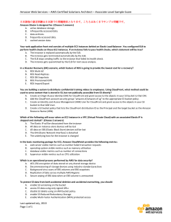
Wheel Loaders L 524 - L 542 Tipping load, articulated: 7,300 kg – 9,760 kg L524-L542_05_2012.indd 1 11.05.12 12:08 12:07 L 524 L 528 L 538 Tipping load, articulated: 7,300 kg Bucket capacity: 2.0 m³ Operating weight: 10,600 kg Engine output: 86 kW Tipping load, articulated: 8,100 kg Bucket capacity: 2.2 m³ Operating weight: 11,100 kg Engine output: 86 kW Tipping load, articulated: 9,020 kg Bucket capacity: 2.5 m³ Operating weight: 12,755 kg Engine output: 105 kW L 542 Tipping load, articulated: 9,760 kg Bucket capacity: 2.7 m³ Operating weight: 13,320 kg Engine output: 105 kW 2 L 524 - L 542 L524-L542_05_2012.indd 2 11.05.12 12:08 12:07 Economy The Liebherr driveline combined with low operating weight and high tipping load results in up to 25% less fuel consumption compared with conventionally driven wheel loaders. Up to 5 litres of fuel per operating hour can be saved, which means lower operating costs and an active protection of the environment at the same time. Performance The Liebherr driveline enables the diesel engine to be installed in the ideal position. For this class of wheel loader, it is transversely mounted at the rear. This greatly increases the tipping load and the handling capacity per operating hour at a lower operating weight than conventional wheel loaders. Reliability All the materials used have passed long-time tests to ensure that they comply with Liebherr’s high quality standards in even the toughest conditions. A sophisticated concept and proven quality mean that Liebherr wheel loaders set the standard when it comes to reliabilty. Comfort The ultra-modern cabin design with advanced ergonomics, continuously variable Liebherr driveline for uninterrupted tractive force, optimal weight distribution and a transversely-mounted engine for excellent maintenance access lead to unequalled overall comfort. L 524 - L 542 L524-L542_05_2012.indd 3 3 11.05.12 12:08 12:07 Lower fuel consumption • A fuel saving of up to 5 litres per operating hour represents a cost saving of up to 25%. • The Liebherr standard test demonstrates the operating efficiency of Liebherr wheel loaders. 4 L 524 - L 542 L524-L542_05_2012.indd 4 11.05.12 12:08 12:07 Economy The Liebherr driveline combined with low operating weight and high tipping load results in up to 25% less fuel consumption compared with conventionally driven wheel loaders. Up to 5 litres of fuel per operating hour can be saved, which means lower operating costs and an active protection of the environment at the same time. Low operating costs Minimum costs, high handling capacity When it comes to economy, conventional wheel loaders are no match for Liebherr machines, mainly due to the following factors: −Low fuel consumption as a result of higher efficiency and a lower operating weight. The Liebherr wheel loader’s fuel consumption is up to 5 litres per operating hour lower than a conventional wheel loader under the same working conditions. − Virtually no brake wear, thanks to the hydraulic braking action of the driveline. This means no brake repair costs resulting from wear and tear. −Continuous traction control for reduced tyre wear. Depending on the working conditions, tyre wear can be up to 25% lower than with conventional wheel loaders. Active environmental protection Economical use of resources Reduced fuel consumption means lower emissions, which leads to the active and economical use of resources. During combustion, 1 litre of diesel produces up to 3 kg of CO2. A saving of 5 litres of fuel per operating hour translates into a 15,000-kilogram reduction in CO2 emissions over a period of 1,000 operating hours, for example. The result: reduced fuel costs and active protection of the environment. Low noise emissions The innovative driveline concept also cuts noise emissions considerably: Liebherr wheel loaders are significantly quieter in operation. Reduced brake wear Reduced tyre wear • Even in the toughest working conditions, the Liebherr travel drive is always braked hydraulically. The mechanical service brake is used only as a secondary braking function, so the brakes are virtually wear-free. • The tractive force can be adjusted continuously. This prevents wheelspin and reduces tyre wear by up to 25%. L 524 - L 542 L524-L542_05_2012.indd 5 5 11.05.12 12:08 12:07 Liebherr driveline •Optimum weight distribution due to transverse installation of the diesel engine. •The diesel engine is used as a counterweight - so high tipping load at low operating weight. •Compact design improves visibility in all directions. 6 L 524 - L 542 L524-L542_05_2012.indd 6 11.05.12 12:08 12:07 Performance The Liebherr driveline enables the diesel engine to be installed in the ideal position. For this class of wheel loader, it is transversely mounted at the rear. This greatly increases the tipping load and the handling capacity per operating hour at a lower operating weight than conventional wheel loaders. Higher performance, lower weight Higher productivity, lower operating weight Liebherr’s driveline enables the diesel engine to be installed transversely at the rear of the wheel loader. This increases the tipping load while keeping the operating weight low. Productivity is greatly increased because no unnecessary counterweight has to be carried on the machine. Ultra-modern Liebherr driveline Innovative technology Tractive force and speed are adapted to suit demand – automatically and without gear changes. Even the change from forward to reverse travel is controlled hydraulically, so that no mechanical reverse gear is required. Flexibility puts them ahead An all-purpose loader The Allround wheel loader models can be supplied with either a parallel or a Z-pattern linkage. This gives them the ideal equipment for tackling a variety of tasks. Their compact design allows these wheel loaders to manoeuvre quickly and efficiently – an ideal basis for high handling capacity. Conventional travel gear An all-purpose loader •Longitudinally mounted diesel engine moves the centre of gravity further forward. •The choice between parallel (P) and Z-pattern linkage means that the loader can always be configured to suit the customer’s specific tasks: P for industrial use, Z for conventional material handling. •Much more additional counterweight is needed to maintain stability and to increase the tipping load. •This leads to high operating weight and bad visibility. L 524 - L 542 L524-L542_05_2012.indd 7 7 11.05.12 12:08 12:07 Liebherr driveline • The Liebherr driveline consists of two hydraulic motors, which accelerate the loader continuously from a standstill to maximum speed, either forwards or in reverse – without a manual gear shift and a reversing gear unit. 8 L 524 - L 542 L524-L542_05_2012.indd 8 11.05.12 12:08 12:07 Reliability All the materials used have passed long-time tests to ensure that they comply with Liebherr’s high quality standards in even the toughest conditions. A sophisticated concept and proven quality mean that Liebherr wheel loaders set the standard when it comes to reliability. Reliable Liebherr driveline Fewer components Liebherr’s driveline includes a self-locking hydraulic brake, with the result that the additional wet brake discs are effectively wear-free. A reversing gear unit is not required, so less parts are affected by wear. Controlled cooling The intelligent answer The cooling fan is not driven directly from the diesel engine, and produces only the cooling air output that is needed at any given moment. Heat sensors control its operating speed, and if overheating should occur, the wheel loader shifts down automatically to the lowest travel speed range. Since less power is then consumed, the diesel engine is better protected against overheating. At the same time, the fan speed is increased to the maximum value, for the best possible protection of all components. Components to the manufacturer’s quality standards Everything from a single source Important components such as the engine, hydraulic rams and electronics are manufactured by Liebherr itself – which means coordinated quality from the manufacturer down to the smallest detail to ensure the highest possible performance and reliability. Cooling system Liebherr’s own components • The radiator is installed on the rear section of the vehicle, between the diesel engine and the cabin. Cooling air is drawn in directly behind the cabin and blown out upwards at the rear. The fan speed is varied automatically by heat sensors that determine the amount of cooling needed. • Liebherr has many years of experience in the design, development and construction of diesel engines, hydraulic rams and electronic components. They are all matched together down to the smallest detail for use on its wheel loaders. • A reversible fan drive to expel dust from the radiator can be specified as an optional extra. L 524 - L 542 L524-L542_05_2012.indd 9 9 11.05.12 12:08 Liebherr control lever • The Liebherr control lever is used to manage all the machine’s travel and working movements. The operator’s left hand can remain on the steering wheel at all times without having to reach for other control levers – a valuable safety feature. The operator controls the following functions with his right hand: –Raise and lower attachment –Fill and dump the bucket –Automatic bucket repositioning Change of travel direction with simultaneous – travel start –Controls for additional hydraulic functions 10 L 524 - L 542 L524-L542_05_2012.indd 10 11.05.12 12:08 Comfort The ultra-modern cabin design with advanced ergonomics, continuously variable Liebherr driveline for uninterrupted tractive force, optimal weight distribution and a transversely-mounted engine for excellent maintenance access lead to unequalled overall comfort. Top-class cabin design Comfort cabin This ultra-modern, ergonomically planned cabin design is the basis for increased performance and productivity of the operator. The displays, controls and driver’s seat are carefully coordinated to form a perfect ergonomic unit. Liebherr control lever All working and travel functions are operated precisely and sensitively from a single control lever. This means accurate and safe handling, and the left hand always remains on the steering wheel. This increases the safety at the job site. Liebherr driveline Continuously variable transmission Liebherr’s driveline enables the wheel loader to accelerate smoothly and continuously in all speed ranges, with no discernable gear shifts and no interruptions to tractive force. Unique oscillation system The combination of centre pivot and rear swing axle reduces the cab tilt by 50% and this again makes the working conditions much more pleasant for the operator. Service accessibility Straightforward maintenance The transversely-installed diesel engine allows excellent ease of access for maintenance. All maintenance points can be reached easily and safely from ground level when a single engine hood is opened. Hydrostatic fan drive The cooling system is located directly behind the cabin. This reduces the accumulation of dust and therefore the need for cleaning and maintenance work, which in turn saves both time and money. Service accessibility Unique oscillation system • The transverse engine facilitates maintenance. Lifting a hinged cover allows safe and convenient access to all maintenance points from ground level. • The combination of centre pivot and rear swing axle reduces the cab tilt by 50%. This leads to greater operator comfort based on the reduction of the cab tilt. – Initial position –Liebherr wheel loader – Conventional wheel loader – Lateral slope angle L 524 - L 542 L524-L542_05_2012.indd 11 11 11.05.12 12:08 Technical Data Engine L 524 L 528 L 538 Diesel engine����������������������� 4045 HF 286 4045 HF 286 D 934 S A6 Design������������������������� 4-cylinder, inline engine, water-cooled, charged, intercooled L 542 D 934 S A6 turbo Rated output according to ISO 9249�������������� kW86 86 105 105 at RPM2,400 2,400 2,000 2,000 Max. torque�������������� Nm430 430 770 770 at RPM1,500 1,500 1,000 – 1,300 1,000 – 1,300 Displacement����������� Liter4.5 4.5 6.36 6.36 �������������� Bore/Stroke mm106/127 106/127 122/136 122/136 Air cleaner system����������������� Dry air filter with main and safety element, pre- cleaner, service indicator on LCD display Electrical system ���������� Operating voltage V24 24 24 24 Battery������������������ Ah/V2 x 135/12 2 x 135/12 2 x 135/12 2 x 135/12 Alternator ��������������������� Three-phase Three-phase Three-phase Three-phase AC AC AC AC V/A24/55 24/55 28/80 28/80 Starter������������������ V/kW24/7 24/7 24/5.4 24/5.4 The exhaust emissions are below the limits in stage IIIA / Tier 3. Travel Drive Stepless hydrostatic travel drive Design ������������������������ Swash plate type variable flow pump and two variable axial piston motors in closed loop circuit and axle transfer case. Direction of travel is reversed by changing the flow-direction of the variable-displacement pump Filtering system �������������� Suction filter for closed circuit Control������������������������ By travel and inching pedal. The inching pedal makes it possible to control the tractive and thrust forces steplessly at full engine speed. The Liebherr joystick is used to control forward and reverse travel Travel speed range���������������� Speed range 1���������������������������� 0 – 6.0 km/h Speed range A1-2������������������������ 0 – 16.0 km/h Speed range A1-3������������������������ 0 – 40.0 km/h The quoted speeds apply with the tyres that are standard equipment on the loader Axles Four-wheel drive Front axle��������������������������� Fixed Rear axle ��������������������������� Centre pivot, with 6° oscillating angle to each side. 470 mm in height can be driven over (with all four wheels remain in contact with the ground) Differentials������������������������� Automatic limited-slip differentials with 45% locking action in both axles Reduction gear��������������������� Planetary final drive in wheel hubs ������������������������� Track width 1,960 mm with all types of tyres (L 524, L 528) 1,900 mm with all types of tyres (L 538, L 542) Brakes Wear-free service brake����������� Self-locking of the hydrostatic travel drive (acting on all four wheels) and additional pump-accumulator brake system with wet multi-disc brakes located in the differential housing (two seperate brake circuits) Parking brake���������������������� Electro-hydraulically actuated spring-loaded disc brake system on the front axle Attachment Hydraulics Design������������������������������ “Load-Sensing” variable axial piston pump with output and flow control, and pressure cut-off in the control block Cooling������������������������������ Hydraulic oil cooling using thermostatically controlled fan and oil cooler Filtration���������������������������� Return line filter in the hydraulic reservoir Control������������������������������ “Liebherr joystick” with hydrostatic servo control Lift circuit��������������������������� Lifting, neutral, lowering and float position controlled by Liebherr joystick with detent; automatic lifting-limit circuit optional Tilt circuit��������������������������� Tilt back, neutral, dump automatic bucket positioning L 524 L 528 L 538 L 542 �������������������� Max. flow l/min.105 105 140 140 Max. pressure������������������ bar315 315 330 330 Attachment Geometry can be chosen��������� Powerful Z-bar linkage with one tilt cylinder, hydr. quick-hitch – optional equipment Parallel linkage with two tilt cylinders, hydr. quick-hitch – standard equipment Bearings���������������������������� Sealed � ������� Cycle time at nominal load L 524 L 528 L 538 L 542 ZK PK ZK PK ZK PK ZK PK Lifting�������������������������� 6.6 s 6.6 s 6.6 s 6.6 s 5.9 s 5.9 s 5.9 s 5.9 s Dumping���������������������� 1.8 s 3.5 s 1.8 s 3.5 s 1.6 s 3.5 s 1.6 s 3.5 s Lowering (empty)������������� 4.0 s 4.0 s 4.0 s 4.0 s 4.0 s 4.0 s 4.0 s 4.0 s Operator’s Cab Design�����������������������_______On elastic bearing on rear section, soundproof ROPS/FOPS cab. Operator’s door with optional sliding window, 180° opening angle, fold-out window on right side with opening angle, front windscreen made of compound safety glass, green tinted as standard, side windows made of single-pane safety glass, grey tinted, continuously adjustable steering column and joystick control as standard, heatable rear window ROPS roll over protection per DIN/ISO 3471/ EN 474-3 FOPS falling objects protection per DIN/ISO 3449/ EN 474-1 Liebherr Operator’s seat���������� 6 way adjustable seat with lap belt, vibration damping and suspension adjustable for the opera tor’s weight Cab heating and ventilation������� Operator’s cab with 4-level air control, cooling water heating, defroster and air conditioning with electronic valve control, as well as electronic fresh/recirculated air control, filter system with pre-filter, fresh air filter and recirculated air filter, easily replaced, air condition optional Noise Emission L 524 ISO 6396 LpA (inside cab)��������������� 69 dB(A) 2000/14/EC LWA (surround noise)��������� 101 dB(A) L 528 L 538 L 542 69 dB(A) 69 dB(A) 69 dB(A) 101 dB(A) 102 dB(A) 102 dB(A) L 528 170 L 538 170 L 542 170 12 3.8 16.3/2.6 15/2.6 110 170 29 3.8 16.3/2.6 15/2.6 110 180 29 3.8 16.3/2.6 15/26 110 180 The braking system meets the requirements of the EC guidelines 71/320. Capacities Steering Design������������������������������ Hydraulic servo power steering Central oscillating frame articulation with damper element Articulation angle������������������ 40° (to each side) Oscillating angle������������������� 6° (to each side) Max. pressure���������������������� 230 bar Emergency steering��������������� Electro-hydraulic emergency steering system 12 L 524 – L 542 L 524 Fuel tank��������������������������� l170 Engine oil (inclusive filter change)����������� l12 Pump distributor gears����������� l3.8 Front axle/wheel hubs ����������� l16.3/2.6 Rear axle/wheel hubs ������������ l15/2.6 Hydraulic tank �������������������� l110 Hydraulic system, total����������� l170 Z-bar Linkage 60° 45° E F D C B A I H J G K L A B C D E F G H I J K L L 524 Bucket type Cutting tools Bucket capacity according to ISO 7546 ** Bucket width Specific material weight Dumping height at max. lift height Dump-over height Max. height of bucket bottom Max. height of bucket pivot point Max. operating height Reach at max. lift height Digging depth Height above cab Height above exhaust Ground clearance Wheelbase Overall length Turning circle radius over outside bucket edge Breakout force (SAE) Tipping load, straight * Tipping load, articulated at 40° * Operating weight * Tyre sizes GPB T 2.0 2,500 1.8 2,870 3,335 3,530 3,775 4,860 850 80 3,200 2,860 460 2,750 6,720 L 528 L 538 L 542 QH T LMB BOCE GPB T QH T LMB BOCE GPB T QH T LMB BOCE GPB T QH T LMB BOCE 1.7 2,500 1.8 2,765 3,320 3,530 3,775 4,915 900 80 3,200 2,860 460 2,750 6,835 2.4 2,500 1.0 2,660 3,320 3,525 3,775 5,160 1,075 80 3,200 2,860 460 2,750 7,245 2.2 2,500 1.8 2,800 3,335 3,530 3,775 4,960 935 80 3,200 2,860 460 2,850 6,930 2.0 2,500 1.8 2,700 3,320 3,530 3,775 5,030 980 80 3,200 2,860 460 2,850 7,035 3.0 2,750 1.0 2,550 3,330 3,531 3,775 5,230 1,120 80 3,200 2,860 460 2,850 7,240 2.5 2,500 1.8 2,900 3,480 3,680 3,930 5,170 960 80 3,250 2,910 490 2,975 7,150 2.2 2,500 1.8 2,770 3,475 3,680 3,930 5,230 1,015 80 3,250 2,910 490 2,975 7,280 3.5 2,750 1.0 2,606 3,475 3,681 3,928 5,530 1,165 80 3,250 2,910 490 2,975 7,605 2.7 2,500 1.8 2,845 3,480 3,680 3,930 5,260 1,005 80 3,250 2,910 490 2,975 7,225 2.4 2,500 1.8 2,740 3,480 3,680 3,930 5,290 1,050 80 3,250 2,910 490 2,975 7,335 4.0 2,750 1.0 2,505 3,476 3,688 3,930 5,590 1,265 80 3,250 2,910 490 2,975 7,695 m3 mm t/m3 mm mm mm mm mm mm mm mm mm mm mm mm mm kN kg kg kg 5,520 5,550 5,620 91 85 83 8,310 7,500 7,320 7,300 6,600 6,430 10,600 10,780 11,055 17.5R25 L3 5,660 5,690 5,840 80 76 73 9,180 8,380 8,130 8,100 7,400 7,180 11,100 11,330 11,470 17.5R25 L3 5,840 5,880 6,045 113 102 96 10,210 9,250 9,135 9,020 8,180 8,060 12,755 12,915 13,090 20.5R25 L3 5,870 5,910 6,100 105 96 81 11,040 10,220 9,931 9,760 9,040 8,760 13,320 13,530 13,805 20.5R25 L3 *The figures shown here are valid with tyres above, includes all lubricants, a full fuel tank, the ROPS/FOPS cab and the operator. Different tyres and optional equipment will change the operating weight and tipping load. (Tipping load, articulated at 40° according to ISO 14397-1) **Actual bucket capacity may be approx. 10% larger than the calculation according to ISO 7546 standard. The degree to which the bucket can be filled depends on the material – see page 17. GPB = General purpose bucket (Rehandling bucket) QH = quick-hitch LMB = Light material bucket T = Welded-on tooth holder with add-on teeth BOCE= Bolt-on cutting edge L 524 – L 542 13 Parallel Linkage 40º E 45º E F A F D B A I H J G L K A B C D E F G H I J K L L 524 Bucket type Cutting tools Bucket capacity according to ISO 7546 ** Bucket width Specific material weight Dumping height at max. lift height Dump-over height Max. height of bucket bottom Max. height of bucket pivot point Max. operating height Reach at max. lift height Digging depth Height above cab Height above exhaust Ground clearance Wheelbase Overall length Turning circle radius over outside bucket edge Breakout force (SAE) Tipping load, straight * Tipping load, articulated at 40° * Operating weight * Tyre sizes L 528 L 538 L 542 LMB LMB HDB LMB LMB HDB LMB LMB HDB LMB LMB HDB BOCE BOCE BOCE BOCE BOCE BOCE BOCE BOCE BOCE BOCE BOCE BOCE m3 mm t/m3 mm mm mm mm mm mm mm mm mm mm mm mm 3.0 2,750 1.0 2,630 3,380 3,595 3,835 5,290 1,220 55 3,200 2,860 460 2,750 7,255 5.5 2,750 0.5 2,230 3,380 3,595 3,835 5,670 1,630 55 3,200 2,860 460 2,750 7,830 5.0 2,700 0.5 4,479 4,505 3,595 3,835 6,500 1,639 55 3,200 2,860 460 2,750 7,739 mm kN kg kg kg 5,765 5,930 5,925 63 7,686 7,010 6,665 6,754 6,155 5,855 11,929 12,320 12,715 17.5R25 L3 3.5 2,750 1.0 2,550 3,380 3,595 3,835 5,440 1,305 55 3,200 2,860 460 2,850 7,475 6.0 2,750 0.5 2,185 3,380 3,595 3,835 5,450 1,680 55 3,200 2,860 460 2,850 8,000 5.5 2,700 0.5 4,457 4,505 3,595 3,835 6,630 1,666 55 3,200 2,860 460 2,850 7,874 5,905 6,070 5,934 61 8,718 8,065 7,840 7,698 7,120 6,920 12,335 12,750 13,145 17.5R25 L3 4.0 2,750 1.0 2,520 3,430 3,645 3,890 5,460 1,300 35 3,250 2,910 490 2,975 7,765 6.5 2,750 0.5 2,185 3,430 3,645 3,890 5,925 1,650 35 3,250 2,910 490 2,975 8,250 6.0 2,700 0.5 4,480 4,555 3,645 3,890 6,755 1,613 35 3,250 2,910 490 2,975 8,094 6,070 6,240 6,193 80 9,092 8,580 8,375 8,019 7,570 7,385 13,442 13,745 14,220 20.5R25 L3 4.5 2,750 1.0 2,450 3,430 3,645 3,890 5,560 1,370 35 3,250 2,910 490 2,975 7,865 7.0 2,750 0.5 2,135 3,430 3,645 3,890 5,980 1,700 35 3,250 2,910 490 2,975 8,320 6.7 2,950 0.5 4,417 4,555 3,645 3,890 6,820 1,600 35 3,250 2,910 490 2,975 8,194 6,120 6,265 6,340 76 9,969 9,445 9,125 8,793 8,330 8,050 14,041 14,320 14,910 20.5R25 L3 *The figures shown here are valid with tyres above, includes all lubricants, a full fuel tank, the ROPS/FOPS cab and the operator. Different tyres and optional equipment will change the operating weight and tipping load. (Tipping load, articulated at 40° according to ISO 14397-1) **Actual bucket capacity may be approx. 10% larger than the calculation according to ISO 7546 standard. The degree to which the bucket can be filled depends on the material – see page 17. LMB = Light material bucket HDB = High-Dump bucket BOCE= Bolt-on cutting edge 14 L 524 – L 542 Parallel Linkage High Lift Light Material Bucket High-Dump Bucket 35º E E 45º A F F A Light Material Bucket with Bolt-On Cutting Edge A E F L Bucket capacity Bucket width Specific material weight Dumping height at max. lift height Max. operating height Reach at maximum lift height Overall length Tipping load, straight * Tipping load, articulated at 40° * Operating weight * Tyre sizes m3 mm t/m3 mm mm mm mm kg kg kg High-Dump Bucket with Bolt-On Cutting Edge A E F L Bucket capacity Bucket width Specific material weight Dumping height at max. lift height Max. operating height Reach at maximum lift height Overall length Tipping load, straight * Tipping load, articulated at 40° * Operating weight * Tyre sizes m3 mm t/m3 mm mm mm mm kg kg kg L 524 L 528 L 538 L 542 4.0 2,750 0.5 3,050 5,950 1,355 8,165 5,510 4,840 12,500 17.5R25 L3 4.5 2,750 0.5 2,980 6,050 1,425 8,365 6,380 5,635 12,930 17.5R25 L3 5.0 2,750 0.5 2,960 6,140 1,404 8,635 7,020 6,190 13,905 20.5R25 L3 5.5 2,750 0.5 2,855 6,250 1,505 8,780 7,655 6,750 14,530 20.5R25 L3 L 524 L 528 L 538 L 542 3.5 2,500 0.5 5,260 6,915 1,468 8,257 5,045 4,430 12,820 17.5R25 L3 4.0 2,700 0.5 5,260 6,975 1,468 8,357 5,940 5,245 13,255 17.5R25 L3 4.5 2,700 0.5 5,269 7,085 1,446 8,612 6,485 5,720 14,320 20.5R25 L3 5.0 2,700 0.5 5,246 7,160 1,479 8,652 7,310 6,450 14,925 20.5R25 L3 *The figures shown here are valid with tyres above, includes all lubricants, a full fuel tank, the ROPS/FOPS cab and the operator. Different tyres and optional equipment will change the operating weight and tipping load. (Tipping load, articulated at 40° according to ISO 14397-1) L 524 – L 542 15 Attachment Fork Carrier and Fork F min. F max. FEM III (500) FEM IV (600) E C A F G L Fork Carrier and Fork with quick-hitch A C E F F max. F min. G L Fork Geometry Lifting height at max. reach mm Max. lifting height mm Max. operating height mm Reach at loading position mm Max. reach mm Reach at max. lifting height mm Fork length mm Length – basic machine without forks mm Tipping load, straight * kg Tipping load, articulated at 40° * kg Recommended payload ** kg Recommended payload *** kg Operating weight * kg Tyre sizes L 524 ZK 1,690 3,580 4,510 975 1,625 695 1,200 PK 1,690 3,645 4,560 1,110 1,720 780 1,200 6,090 6,225 5,755 6,315 5,055 5,550 3,035 3,330 4,045 4,440 10,525 11,370 17.5R25 L3 L 528 ZK 1,693 3,592 4,513 969 1,619 698 1,200 L 538 FEM III PK ZK 1,693 1,781 3,650 3,738 4,565 4,662 1,104 939 1,720 1,635 774 694 1,200 1,200 6,190 6,330 6,410 7,205 5,660 6,360 3,395 3,820 4,1501) 5,0002) 10,905 11,735 17.5R25 L3 PK 1,739 3,697 4,612 975 1,635 695 1,200 6,350 6,390 7,225 7,610 6,375 6,715 3,825 4,030 5,0002) 5,0002) 12,500 12,690 20.5R25 L3 L 542 ZK 1,780 3,740 4,664 937 1,631 683 1,200 PK 1,739 3,699 4,613 974 1,631 684 1,200 6,350 6,390 7,970 8,355 7,030 7,370 4,220 4,420 5,0002) 5,0002) 13,035 13,225 20.5R25 L3 L 538 ZK 1,760 3,710 4,695 955 1,615 675 1,200 L 542 FEM IV PK ZK 1,715 1,760 3,665 3,710 4,610 4,695 995 955 1,610 1,615 975 675 1,200 1,200 6,325 6,370 7,110 7,510 6,270 6,620 3,765 3,975 5,020 5,300 12,736 12,926 20.5R25 L3 PK 1,715 3,665 4,610 995 1,610 975 1,200 6,325 6,370 7,860 8,260 6,935 7,285 4,160 4,370 5,1651) 5,830 13,274 13,464 20.5R25 L3 *The figures shown here are valid with tyres above, includes all lubricants, a full fuel tank, the ROPS/FOPS cab and the operator. Different tyres and optional equipment will change the operating weight and tipping load. (Tipping load, articulated at 40° according to ISO 14397-1) ** for uneven ground = 60% of tipping load (articulated at 40°) (according to EN 473-3) ***for smooth surfaces = 80% of tipping load (articulated at 40°) (according to EN 473-3) 1) Payload on forks is limited by tilt cylinder 2) Load capacity for the fork carrier and forks is limited to 5,000 kg ZK= Z-bar linkage PK= Parallel linkage 16 L 524 – L 542 Tipping Load ISO 14397-1 What is tipping load? Load at centre of gravity of working equipment, so that the wheel loader just begins to tip over the front axle. This the most unfavourable static-load posi tion for the wheel loader. Lifting arms horizontal, wheel loader fully articulated at centre pivot. Pay load. The pay load must not exceed 50% of the tipping load when articulated. This is equivalent to a static stability-margin factor of 2,0. Bucket capacity = Bulk Material Densities and Bucket Filling Factors Gravel, moist dry crushed stone Sand, dry wet Gravel and sand,dry wet Sand / clay Clay, natural dry Clay / gravel, dry wet t/m3 1.9 1.6 1.5 1.5 1.9 1.7 2.0 1.6 1.6 1.4 1.4 1.6 % 105 105 100 110 110 105 100 110 110 110 110 100 Bucket capacity. The bucket volume is determined from the pay load. Tipping load, articulated Pay load = 2 Earth, dry wet excavated Topsoil Basalt Granite Sandstone Slate Bauxite Limestone Gypsum, broken Coke Slag, broken t/m3 1.3 1.6 1.1 1.95 1.8 1.6 1.75 1.4 1.6 1.8 0.5 1.8 % 115 110 110 100 95 100 100 100 100 100 110 100 Pay load (t) Specific bulk weight of material (t/m3) Glass waste, broken solid Compost, dry wet Wood chips / saw dust Paper, shredded / loose recovered paper / cardboard Coal, heavy material density light material density Waste, domestic waste bulky waste t/m3 1.4 1.0 0.8 1.0 0.5 0.6 1.0 1.2 0.9 0.5 1.0 % 100 100 105 110 110 110 110 110 110 100 100 Tyres Size and tread code L 524/L 528 Bridgestone 17.5R25 VJT L3 Bridgestone 17.5R25 VSDL L5 Goodyear 17.5R25 RT-3B L3 Goodyear 17.5R25 RL-5K L5 Goodyear 17.5R25 RL-4K L4 Michelin 17.5R25 XTLA L2 Michelin 17.5R25 XHA L3 Michelin 17.5R25 XLD D2A L5 Michelin 17.5R25 X-MINE D2 L5 L 538/L 542 Bridgestone 20.5R25 VJT L3 Bridgestone 20.5R25 VSDL L5 Goodyear 20.5R25 RL-5K L5 Goodyear 20.5R25 RL-4K L4 Goodyear 20.5R25 RT-3B L3 Goodyear 20.5R25 TL-3A+ L3 Goodyear 20.5R25 GP-4D L4 Michelin 20.5R25 XHA2 L3 Michelin 20.5R25 XLD D2A L5 Michelin 20.5R25 X-Mine D2 L5 Change of operating weight kg Width over tyres mm Change in vertical dimensions mm + 88 + 584 + 168 + 680 + 556 – 68 0 + 363 + 548 2,450 2,450 2,470 2,470 2.490 2,470 2,460 2,480 2,480 + 21 + 57 + 21 + 42 + 33 – 6 0 + 37 + 54 Bulk material Stone, Recycling Gravel Industry, Stone Industry, Stone Gravel, Earthworks Gravel Stone, Recycling Stone, Recycling + 12 + 672 + 624 + 588 + 16 + 156 + 328 + 0 + 428 + 696 2,470 2,470 2,490 2.490 2,480 2,480 2,470 2,480 2,490 2,480 – 6 + 36 + 47 + 33 + 5 + 5 + 18 0 + 30 + 43 Bulk material Stone, Scrap Industry, Stone Industry, Stone Gravel Gravel, Earthworks Sand, Gravel, Industry Gravel Stone, Mining spoil, Recycling Stone, Scrap Use Before operating the vehicle with tyre foam filling or tyre protection chains, please discuss this with the Liebherr-Werk Bischofshofen GmbH. L 524 – L 542 17 The Liebherr Wheel Loaders Stereoloader L 506Stereo 3,231 0.8 5,120 46/63 Tipping load kg Bucket capacity m 3 Operating weight kg Engine output kW/HP L 507Stereo 3,501 0.9 5,240 48/65 L 508Stereo 3,824 1.0 5,480 48/65 L 509Stereo 4,225 1.1 6,080 60/82 L 510Stereo 4,581 1.2 6,250 60/82 L 514Stereo 5,680 1.5 8,350 72/98 Wheel Loader Tipping load kg Bucket capacity m3 Operating weight kg Engine output kW/HP L 524 7,300 2.0 10,600 86/117 L 528 8,100 2.2 11,100 86/117 L 538 9,020 2.5 12,755 105/143 L 542 9,760 2.7 13,320 105/143 L 550 11,650 3.2 16,525 129/175 L 556 13,140 3.6 17,270 140/191 L 566 15,550 4.0 22,500 190/259 L 576 17,200 4.5 24,260 200/272 L 580 18,000 5.0 24,580 200/272 L 586 20,430 5.5 31,380 250/340 Wheel Loader Tipping load kg Bucket capacity m3 Operating weight kg Engine output kW/HP 07.10 Environmental protection can help you earn money! 5 n=? 35 4 T ~ 35 sec. 25 20 m 30 2,5 m B 20 15 A 3 The Liebherr Standard Consumption Test – easy to reproduce and practical. Every Liebherr dealer will provide you with this measuring-tank kit free of charge or, on request, will carry out the standard fuel consumption test on your premises. It’s so easy: you simply determine the number of loading cycles that can be carried out with 5 litres of diesel. The material is taken from pile A and carried over a distance of 20 metres to point B. The time needed for each working cycle should be 35 seconds. Discharge at point B should take place from a height of 2.5 m. The working cycles continue until the 5 litres of diesel in the external measuring tank have been used up. The loader’s fuel consumption per operating hour is calculated as follows: 400 Number of loading cycles = consumption per hour 2 1 Values for the Liebherr Wheel Loaders Numbers of Litres/ Litres/ working cycles 100 tons hour L 524: 2.0 m3 n = 44 3.2 9.1 L 528: 2.2 m3 n = 43 2.9 9.3 L 538: 2.5 m3 n = 36 2.9 11.1 L 542: 2.7 m3 n = 35 2.7 11.4 L 550: 3.2 m3 n = 31 2.6 12.9 L 556: 3.6 m3 n = 27 2.9 14.5 L 566: 4.0 m3 n = 22 2.9 18.2 L 576: 4.5 m3 n = 21 2.9 19.1 L 580: 5.0 m3 n = 20 2.8 20.0 L 586: 5.5 m3 n = 14 3.2 28.5* * Equipped with L5 tires and 5.5 m3 HD bucket 18 L 524 – L 542 • • • • • • • • • • • • 542 542 538 538 528 528 524 52 • • • • • • • 542 • • • • Equipment Automatic hoist kick out – adjustable Automatic bucket positioner – adjustable Fork carrier and lift forks High-dump bucket Log grapple Hydraulic quick-hitch – Parallel linkage Hydraulic quick-hitch – Z-bar linkage Hydraulic servo control of working hydraulics Comfort control Loading buckets with and without teeth, or bolt-on cutting edge Country-specific versions Light material bucket Parallel linkage Parallel linkage “High Lift” Float position Z-bar linkage 3rd hydraulic control circuit 3rd and 4th hydraulic control circuits • • • • • • • • • + • • • • + + • • • • • • • • • • • • + • • • • + + • • • • • • • • • • • • + • • • • + + • • • • • • • • • • • • + • • • • + + • • • • • • • • • • 54 • + + • + + + + + • + • + • • + • • • • • • • + • + + + • + • + + + + + + • • + + + • + + + • + • + + + + + + • • + + + • + + + • + • + + + + + + • • + + + • + + + • + • + + + + + + • • + + • = Standard, + = Option L 524 – L 542 19 524-542 05.12 • • + + • + + + + + • + • + • • + • • • • • • • 538 • • + + • + + + + + • + • + • • + • • • • • • • • • • • • • 528 • • + + • + + + + + • + • + • • + • • • • • • • • • • • • • 538 • Function Keys for: Electronic tractive force adaptation Speed range selection Ride control Parking brake Fresh air or recirculated air Blower Heater Hoist kick-out Air conditioning Creep speed Mode switch Amber beacon Automatic bucket positioner Wash/wipe system for rear window Headlights Float position Road travel Hazard warning flashers Additional hydraulics • • • • • • • • • • • • • 528 • • • • • + + • + • + • • + • + + + • + Warning Lights for: Battery charge Flow through emergency steering system Parking brake Hydraulic oil temperature Air cleaner blockage Engine oil pressure Engine overheat • • • • • • • • • • • • • 524 • • • • • + + • + • + • • + • + + + • + Instruments for: Timer for hours of operation Flashing turn indicators Diagnosis system Forward – reverse travel Travel speed ranges and gear selected High-beam headlights Fuel reserve Engine oil temperature Reverse travel Speedometer Clock Diesel engine pre-heat Forward travel 524 542 542 • • • • • + + • + • + • • + • + + + • + 542 538 538 • • • • • + + • + • + • • + • + + + • + 538 528 + • + + • + + + • • + • + + + • • • + • + • • • + • + 528 + • + + • + + + • • + • + + + • • • + • + • • • + • + 524 Audible Warnings for: Overheat of hydraulic fluid Engine oil pressure Engine overheat Emergency steering system + • + + • + + + • • + • + + + • • • + • + • • • + • + 528 Operator’s Cab Storage box Lockable storage compartment Ashtray Operator’s package Operator’s seat – adjustable in 6 ways Operator’s seat – air sprung with seat heating Fire extinguisher 2 kg Cup holder Height-adjustable steering column Horn Joystick steering Floor mat Clothes hook Air conditioning system Liebherr-joystick control – adjustable Radio set Provision for radio including loudspeaker Monitoring area to the rear with camera Interior rear-view mirror Amber beacon Soundproof ROPS/FOPS cab with tinted safety glass front windscreen, heatable rear window Wash/wipe system for windscreen and rear window Headlights rear, double version – LED Headlights rear, single or double version - halogen Headlights front, double version - halogen Headlights front, double version - LED Headlights front, single version - XENON Sliding window Protective ventilation system Windscreen guard Sun visor Dust filter system Plug 12 V First aid kit Adjustable steering column Hot water heater with defroster and recirculated-air system Wide angle mirror + • + + • + + + • • + • + + + • • • + • + • • • + • + 524 Basic Machine Automatic central lubrication system Battery master switch Fuel particle filter Electronical theft protection Automatic travel mode Ride control Fluff trap for radiator Large-mesh radiator Pre-heat system for cold starting Combined inching-braking system Fuel tank steel version Multi-disc limited slip differentials in both axles LiDAT Standard (Liebherr Data Transfer System) LiDAT Plus (extended Liebherr Data Transfer System) Liebherr bio degredable hydraulic oil Liebherr travel gear Liebherr shock absorbing element Air cleaner system with pre-filter Reversible fan drive Emergency steering system Back-up alarm Tail lights, single version Headlights front, single version (on front-chassis) – halogen Lockable doors, service flap and engine hood Toolbox with toolkit Towing hitch 20 km/h speed limiting 524 Equipment Wide Product Range State-of-the-art Technology The Liebherr Group is one of the largest construction equipment manufacturers in the world. Liebherr’s high-value products and services enjoy a high reputation in many other fields. The wide range includes domestic appliances, aerospace and transportation systems, machine tools and maritime cranes. To provide consistent, top quality products, Liebherr attaches great importance to each product area, its components and core technologies. Important modules and components are developed and manufactured in-house, for instance the entire drive and control technology for construction equipment. Exceptional Customer Benefit Worldwide and Independent Every product line provides a complete range of models in many different versions. With both their technical excellence and acknowledged quality, Liebherr products offer a maximum of customer benefits in practical application. Hans Liebherr founded the Liebherr family company in 1949. Since that time, the enterprise has steadily grown to a group of more than 120 companies with over 35,000 employees located on all continents. The corporate headquarters of the Group is Liebherr-International AG in Bulle, Switzerland. The Liebherr family is the sole owner of the company. www.liebherr.com Printed in Germany by Typodruck RG-BK-RP LBH/PM 10354047-3-05.12_enGB Liebherr-Werk Bischofshofen GmbH Postfach 49, A-5500 Bischofshofen +43 50809 1-0, Fax +43 50809 11385 www.liebherr.com, E-Mail: [email protected] All illustrations and data may differ from standard equipment. Subject to change without notice. The Liebherr Group of Companies


© Copyright 2026