
Document 366710
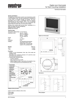
May 5, 1942.
2,282,197
M. J. MAYNARD
COMBUSTION CONTROL SYSTEM
Filed Nov. 25, 1938
T5901
35
‘
I
I
.
, '/?/67¢ A: My
attorney,
‘ Patented May
1942
if _. 2,282,197
UNITED STATES PATENT
OFFICE,
2.232.191 ‘
COMBUSTION couraor. srsram
Meade J. Maynard, Minneapo11!, Min, assignm
to Minneapolis-Honeywell Regulator Company,
Minneapolis, Minn, a corporation of Delaware
vApplication November 25, 11938, Serial No. 242,2“
6 Claims.
'
My invention relates to the control of heating
apparatus employing forced draft and is par
ticularly concerned with improved safety de
vices for controlling draft in relation to fuel
supply in a manner to insure that those prac
' ticing my invention will be exempt from the usu
al hazards attendant to the use of gas and oil
?red heating equipment and various other types
of equipment ?red with fuel burned under forced
draft. Most important among these hazards is,
of course, the danger of introducing an igniter
(Cl. 158-28)
draft air conveys heat away from the device for
actuating it.
‘
Other objects and advantages of my invention
will become apparent from the accompanying
drawing and detailed speci?cation following.
Figure l of the drawing represents a gas ?red ,
warm air heating system having a, preferred form
of my improved control arrangement embodied
therein.
v
Figure 2 is a modi?ed form of my invention. .
Referring to Figure l of the drawing, at i I
such as a spark or ?ame into a combustion cham
have indicated a warm air furnace having a com
ber which has not been properly scavenged and
bustion chamber 2 and a jacket 8 forming a
which may be filled with explosive material in
the form of gas fumes or air laden with minute 15 bonnet for the furnace within which air is heated
for use in rooms or spaces being served. A stack
particles of pulverized solid fuel suspended
therein.
'
or ?ue s
v
M":
‘with the combustion
chamber 2 and an air distributing duct 5 con
The primary object of my invention is to pro
vide improved apparatus for insuring that the ’ nects with the bonnet 3 vi’or conveying air to vari
space: or rooms to be heated, the distributing
draft is always initiated ahead of the fuel sup 20 - one
duct 6 ‘having branch ducts or passages such as
plying means equipment of the above type and
the duct 6 communicating with the individual
is always properly maintained while fuel is being
supplied to the equipment.
rooms. Air is returned from the rooms or spaces
and recirculated through the furnace by means
Another object is to provide an improved de
oi’ a return air duct ‘i communicating'with the
vice for insuring that the proper sequence and 25 lower
part of the jacket 8.
' r
'
V
maintenance of draft and fuel supply are ef
Disposed
within
the
combustion
chamber
2 is a
fected and which can only fail safe, that is, in
conventional gas burner it and fuel is supplied
the event of any casualty to the device itself or
thereto through a conduit H which may be con
otherwise resulting in draft failure, shut down of
the system is always e?‘ected in a manner and o nected to a gas supply main. Interposed in the
conduit ii is a fuel controlvalve l2 whichmay be
according to a sequence maintaining immunity
an electric solenoid type valve as I have shown,
from various dangers and hazards usually char
or it may take the form, of other known fuel con
acteristic of the type of equipment to which my
trol valves now in use. For igniting fuel supplied
invention relates.
‘to the burner it is a constantly burning pilot
A further object is the provision of a fuel supply
burner it which may be supplied with fuel
control device responsive to draft comprising a
through a tube it connected to the conduit il
heat actuated switch arranged to shut oil’ the fuel
ahead of the valve i2. interposed in the tube it
supply in the event of draft failure or of a con
is a small‘ electric solenoid type valve i5 and con
tingency otherwise changing the amount of heat
reaching the switch.
_
A further object is the provision of a draft
responsive device comprising a draft tube having
a heater and a heat actuated switch therein ar
ranged so that the draft carries heat to the switch
for actuating it.
Another objectis the provision of a tempera
. ture control system wherein the fuel'supply means
are controlled by a heat actuated switch, heat for
actuating the switch being carried to it by draft
40
nected to the tube It in by-pas's relation with the
valve i5 is a small by-pass tube I6. Fuel is con
tinually supplied to the valve i3 through the con
duit ii through the tube M, the by-pass i6 and
the continuation of the tube It. Whenever heat
45 within the combustion chamber 2 is to be initiated
as will presently be described, the valve I 5 .is .
‘opened so that fuel may be supplied directly
through the tube it to the pilot burner as well as
through the by-pass It. The tube It is larger
than the by-pass. it so that when the valve I5 is
so that if draft fails the fuel supply means are
open the size of the pilot ?ame is augmented to
shut down.
insure that it will be sumciently large to ignite
the fuel supplied to the burner l0.
Arranged adjacent the ?ame of the pilot burner
\
Another object is the provision of a fuel con
trol system having a draft responsive fuel control
device actuated by heat and arranged so‘ that 55 i3 is a safety pilot. I 9 which may be ‘of conven
tional type comprising a bimetal blade 20 which’
2,282,197
2
is normally heated by the ?ame of the pilot
electrical contact 2|.
burner and engages a ?xed
'
Draft for combustion and for scavenging the
combustion chamber is supplied by a draft fan
‘22, the discharge of which communicates with
. through the combustion chamber 2 for scaveng
ing it to remove any combustible gases which may
have accumulated therein and which may have
remained in an unburned state while. the ap- ‘
paratus was not in operation. Opening of the
small valve I15 admits an additional quantity of
the combustion chamber by means of a conduit
gas to the burner i3 for increasing the size of
The
fan
22
is
driven
‘by
an
electric
motor
the pilot flame to insure ignition at the burner
. 23.
124. Numeral 25 indicates generally a draft re
it when gas is suppplied thereto.- If operation
sponsive control device for controlling the valve
of
the fan 22 is properly initiated and heater 28
10
. l2. The device 25 in the form in which I have
is properly energized as described, heat will/be
chosen to disclose it comprises a Pitot tube 23
carried from the heater downwardly through
having an ori?ce 2'! in a portion of the tube ex- ‘ ' tube‘ 25 and switch blade 29 will be ?exed into
, tending within the conduit 23, the tube and ori
engagement with ?xed contact 33. Upon this
‘ ?ce being so arranged that when the fan 22 is in
occurring a circuit for energizing and opening
15
‘ operation, draft air is forced through the ori?ce
21 and into the tube 26. Disposed within the
tube 26 is an electric heating resistance 28 and
a bimetal switch blade 29 cooperating with a
‘ ‘?xed electrical contact 30. Between the heater
the valve i2 is completed as follows: from line
conductor 33 through thermostat blade 35, ?xed
contact 35, wire til, wire 31, blade 29, ?xed con
tact 33, wire 38, valve l2, wire 49, safety pilot
20 l3, wire 5|!’ back to line conductor l9. Upon
. 23 and thermal switch formed by switch blade 29
completion of this latter circuit, the main valve
is a small ba?e 3| interposed in the path of air
‘ ?owing
downwardly
through
the
tube
23.
I Whenever the heater 28 is energized and draft is
i2 opens admitting gas to the burner l0 which
is ignited by the ?ame of the pilot burner l3 and
heating is initiated within the combustion‘.
- ; being properly supplied through the conduit 23,
chamber 2. Heating will continue under the
‘ air will be forced downwardly through the tube 25 control of thermostat 3 and the draft re
23 and will carry sumclent heat from the heater
28 to the bimetal blade 29 to cause the blade to
flex into engagement with the contact 33 and
therethrough.
sponsive device 25. If ‘draft should fail for
any reason whatever while the heating apparatus
is in operation, the draft responsive device 25 will
‘ complete an electrical circuit
operate to deenergize the valve I2 and shut down _
‘ Upon failure-or discontinuance of the supply of 30 the system. For example, if the motor 24 driv
draft through the conduit 23 the downward cir
culation of air through the tube 26 will stop and
ing the fan 22 should fail causing the pressure '
within conduit 23 to drop, suf?cient heat would
heat will no longer be carried to the blade 29 so
no longer be carried to the blade 23 for causing
that it will assume its original position and
it to flex into engagement with the fixed contact
35
break contact with the ?xed contact 30. At
30.1 Thus the above described circuit for valve
no
pressure
in
the
conduit
times when, there is
I2 would be interrupted and‘the supply of gas to
23, that is, when the draft fan 22 is not operat
burner l3 would be discontinued so as to safely
ing, the chimney e?eot of the tube 26 will cause '
shut down the system. If for some reason the
air to circulate upwardly therethrough- rather
heater 28 should become defective so that it
than downwardly as takes place when the fan 22
is operating. The natural tendency of warm air
should fail to properly supply heat, the blade 29
would ?ex away from the contact 30 in the same
manner and'also shut down the system. Thus it
tube 26 by reason of the heat at heater 28 when
is to be seen that the draft responsive device 25
there is no pressure in conduit 23 for enforcing
45 is arranged so that in the event of any type of
a downward circulation through tube 26.
vto rise will cause an upward circulation of air in ._
Primary control of my system is exercised by
failure or the occurrence of any exigency as
,
might otherwise bring about a dangerous con
a space thermostat 33 which may be of conven- ' Q
dition, the draft device 25 will bring about shut
tional type comprising a bimetal element 3% ar
down of_' the system in a safe' manner. This
ranged to actuate a switch blade 35 cooperating 50 represents an improvement in the art inasmuch
with a ?xed electrical contact 35. The blade 35
as ‘in known devices certain types of failure of _ A
cooperates with a permanent magnet 31 which
the apparatus will cause the safety switch to as
imparts snap opening and closing movements to
.sume a closed rather than an open position which
' the switch formed by the blade 35 and contact 36.
is undesirable. Y
In operation when the temperature of the space
. Whenever the thermostat 33 becomes satis?ed,
being heated falls to a predetermined value, the‘
all of the above described circuits will be inter
blade 35 of thermostat 33 engages with ?xed con
rupted thus closing both the valves l5 and I2
tact 36 and completes electrical circuits energiz
and‘ stopping the fan22 and deenergizing the
ing the fan motor 24, the heater 28 and the small
heater 28. It is to be seen that when-heating is
pilot control valve I5. Numerals 38 and 39 de
initiated the valve I2 is not opened until after
60
signate line conductors connected to a suitable
draft has properly been established through the
source of external power and when the thermo
combustion chamber 2 but when heating is to be
stat closes, the electrical circuit for the'fan motor
terminated the valve I2 is immediately closed in
24 is as ‘follows: from line conductor 33 through
response to the opening of thermostat 33. At
the thermostat blade‘35, ?xed contact 33 wire
times when the apparatus is not in operation,
40, fan motor 24,‘ wire 4|, back to line conductor 65 the valve I5, is closed and only a very small
39. The circuit for the heater 28 is from line
amount of gas is supplied to the burner l3
conductor'38 through the thermostat blade 35, . through the by-pass it.’ Thus the amount of
?xed contact 36, wire 40, wire 42, heater 28, wire
fuel consumed when heating is not required is
43, and wire 4| back to line conductor 39. The
very small andeeconomical.
_ .
'
~
70
circuit for the small valve I5 is from line con
Referring to Figure 2 of the drawing wherein
ductor 38 through thermostat blade 35, ?xed ,
contact 36, wire 40, wire 44, valve l5, wire 45,j
Y, wire 4| back to- line conductor 33.
Upon com- ‘
‘ pletion of the circuits just described the as 22 is
started in operation for enforcing a circulation]5
I have disclosed a second form of my invention, _
the elements of the combination correspond -gen~
erally to those of Figure 1 and are numbered
the same but the draft responsive device is of _
2,262,197
a slightly- different character and operates in a
3
said heating means, an energizing circuit for said
fuel supplying means, draft supplying means for
said heating means, means controlling said draft
slightly different manner. The elements of Fig
ure 2 which differ from the disclosure of Figure
1 are numbered with numbers greater than 100.
It will be noted that in Figure 2 the draft re
sponsive device comprises a mercury switch H9
actuable by a helical thermostatic element I29
disposed in the path of draft air in the conduit
means and a draft responsive device controlling
the fuel supply means, said device comprising
means forming a passageway arranged to divert
draft air from said draft supplying means, a
heater and a heat actuated switching means in
23. Arranged within the helical thermostatic
control of said circuit for said fuel supplying
element I29 is the electrical heating resistance 10 means
arranged so that the draft through said
28 which in this form of the invention is con
passageway carries heat from the heater to the
tinuously energized through'an electrical circuit
switching means for actuating the switching
‘from line conductor 38, wire I42, heater 28, wire
means to one position, the switching means be
I43 back to line conductor 39. In operation,
ing actuated to another position when not heated
when the thermostat 33 of Figure 2 closes indi 15 and said passageway forming means being so ar
cating a need for heating, a circuit for energiz
ranged that air is blown therethrough in one di
ing the fan motor 24 is completed as follows:
rection when the draft supplying means is op
from line conductor 38 through thermostatic
erating and air is drawn therethrough in the ,
blade 35, ?xed contact 36, wire 40, motor 24,
opposite direction when the draft supplying
wire 4| back to line conductor 39. At the same 20 means is not operating.
time a circuit for energizing the small electric
-2. In a control system, in combination, heat~
valve I5 is completed as follows: from line con
ing means, fuel supply means cooperating with
ductor 98 through thermostatic blade v35, ?xed
said heating means, draft supplying means for
contact 36, wire 40, wire 44, valve I5, wire 45,‘
said heating means, means controlling said draft
and wire 4| back to line conductor 39. Upon 25 means
and and a draft responsive device for en
_ completion of the above circuits the draft fan
ergizing the fuel supply means only when said
22 is‘ started in operation and the small fuel
draft suppling means is in operation, said device '
valve I5 is opened, it being understood that the
comprising means forming a passageway adapt
switch H8 controls the valve I2 and is normally
ed to havedraft air pass therethrough, a heater
in an open position under the in?uence of heat 30 arranged in the path of air passing through said
from heater 28 acting upon element I29. As
‘passageway and heat actuated switch means re
soon as draft has‘ properly been established >
sponsive to heat from said heater, vsaid heater
through conduit 23 and the combustion cham
being so positioned that said draft supply means
ber of the furnace a large part of the heat gen
is effective to cause heat from said heater to be
erated by element 28 will be carried away by the 35 carried
away from the switch means tending to
draft air and the draft air will thus cause cool
cool said switch means and thereby cause en- _
ing of the thermostatic element I29 which will
ergizationof said fuel supplying means.
move the switch II8 to a closed position. Upon
3. In an air flow responsive apparatus in com- ‘
closure of switch IIB a circuit for energizing and
opening the main fuel valve I2 will be completed 40 bination, means forming a continuously open
passageway, means for producing a circulation .
as follows: from line conductor 38' through ther
of
?uid through said passageway at a substan
mostatic blade 35, fixed contact 89, wire 40, wire
tially constant rate, means comprising a heat
I41, switch IIB, valve I2, wire I48, wire II back ‘actuated
device and a heat source in said pas
to line conductor 39. Assoon as valve I2 opens
sageway,
said device and source being so rela
heating is initiated and proceeds in the same 45
tively disposed that said device is substantially
manner as described in connection with Figure 1.
unaffected by radiant heat from said heat'source
Should now at any time there be a failure of
and when said circulation producing means is in
the draft within conduit 23 so as to cause the
operation said ?uid passes ?rst over the heat
air therein to become more orv less stagnant the
heat from heater 28 will no longer be carried 50 source and then over the device, and said pas
sageway forming. means being so arranged and
away and element I29 will not be cooled and it
disposed that when said circulation producing
- will cause switch H8 to assume open position
means is not in operation said heat source in
duces a rising convection circulation of fluid
thereby terminating heating. Upon thermostat
33 becoming satis?ed the fan immediately stops
and both valves close.
,
7
From the foregoing it is apparent that the
modi?cation of my invention shown in Figure 2
provides a correspondingly inexpensive but ef
fective system for controlling the fuel valve. or
the like in such a maner that scavenging of
the combustion chamber is always assured and
moreover that safety of operation which is al=
ways a prerequisite of such systems is assured
as well.
'
through said passageway forming means with
55 the ?uid
s first over said device and then
the heat source tending to carry heat away from
the device, and a control device actuated to one
position by said heat actuated device when said
_
fluid passes
?rst over said heater and then over
said device, and to another position when said
?uid passes first over saiddevice and then over
said heater. the ?ow of ?uid through said pas
sdageway being una?fected by said control de
ce.
'
My invention is particularly adapted to a com 65
‘i. Ina heating system, in combination, a com- .
bustion control system in combination with
bustion chamber, a burner positioned to supply
which I have disclosed it but it is to‘ be under
fuel to said combustion chamber, a fuel valve in
stood that it is adaptable to other uses and to
control of ?ow of fuel to said burner,v a blower
use in other combinations and arrangements.
supplying air to said combustion chamber to
Therefore my disclosure is to be interpreted as 70 for
support combustion, a heater positioned to be
illustrative only and I am to be limited only as
subject to flow of air from said blower, means
determined by the appended claims.
including a thermostat in heat transfer relation
I claim as my invention:
to said heater for maintaining said fuel valve'
1. In a control system, in combination, heat
in closed position when no air from said blower
ing means, fuel
i
supply means cooperating with 75 is passing over said heater and for opening said
‘ 4
2,282,107
valve when air from said blower is passing over
said heater, and a condition responsive means in
control of. said blower for starting operation of
said blower to supply substantially full delivery
capacity of said blower to said combustion cham
ber when heat is required in said combustion
chamber and for stopping operation of said blow
' when no heat is required in said combustion
chamber, and an electric circuit passing in series
through said fuel valve, said thermostat and said
condition responsive device, whereby a time inter
val will elapse between the starting of operation '
of said blower and the opening of- said fuel valve
but said fuel valve willclose simultaneously with
stopping of said blower due to the action of said
er when 'no heat is required in-said combustion
condition responsive means.
,
Y.
chamber, whereby full air capacity of said blower
6. In a heating system, in combination, a com
10
is forced through said combustion chamber dur
bustion chamber, a burner positioned to supply
ing the time interval between start of operation
fuel to said combustion chamber, a fuel valve in
of said blower and actuation of said thermostat v control of the-?ow of fuel to said burner, a blow
to open said fuel valve.
,
er for supplying air to said combustion chamber
5. In aheating system, in combination, a-com
to support combustion,‘ means forming a passage
. bustion chamber, a burner positioned ,to supply
way having upper and lower ends, the upper end
fuel to said combustion chamber, a fuel valve
being in communication with saidvblower, said
in control of flow of fuel to said burnena‘blow‘er
means being so disposed that one end of they
for supplying air to said combustion chamber to ‘ passageway is ‘higher than the other end thereof,
support combustion, a heater positioned to be.
a heater positioned within the passageway, means
subject to ?ow of air from said blower, means 20 in control of said valve including a thermostat
including a thermostat in heat transfer relation
located within the passageway at a point between _
to said heater for ‘maintaining said fuel valve
said heater and the lower end of the passage
in closed position when no air from said blower
way for maintaining said fuel valve in closed
is passing over said heater and for ‘opening said
position when no air is passing over said heater
valve when air from said blower is passing over,
due to the action of said blower and for open
said heater, a condition responsive means in con
ing said fuel valve when action of said blower
trol of said blower for starting operation of said
transfers heat from said heater to said thermo
wblower to supply substantially full delivery ca
pacity of said blower to said combustion chamber
when heat is required in said combustion cham-;
her and for stopping operation of said blower
stat.
-
,
-
»
MEADE J. MAYNARD.


© Copyright 2026