
Document 374184
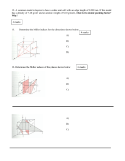
NOV. 4, 1952
v
F. L. VAN WEENEN ETAL
2,616,668
REGENERATOR
Filed April 22, 1948
GZASS‘
WOOL
l0
//
MEfALL/C
Fl 6 |
PART/61.66’
GLASS
WOOL
37m
FIG, 2
WIRE
STEEL
WIRE
INVENTORJ
FPANC/SZ‘US' 'MMBEPTUS V/W WffA/EA/
BY
AGE/V7
2,616,668
Patented Nov. 4, 1952
uNrrEo STA-ms PATENT OFFICE
2,616,668
REGENERATOR
Franciscus Lambertus van Weenen, Gerhart
Wolfgang Rathenau, and Arie Koelewijn, Eind
hoven, Netherlands, assignors to Hartford Na
~ tional Bank and Trust Company, Hartford,
Conn., as trustee
Application April 22, 1948, Serial No. 22,606
In the Netherlands May 30, 1947
1 Claim. (Cl. 257-6)
l
Regenerators as used, for example, in hot-gas
engines and in refrigerating apparatus operating
according to the reversed hot-gas principle have
for their purpose to reduce the temperature of
'the medium ?owing from the hot side to the
2
contained‘ in the ?lling mass and having a co
e?icient of heat-conduction 'higher than 0.03
gram calories per square centimeter per second
per degree centigrade are substantially transverse
to the direction in which the medium ?ows
through the regenerator. In a further embodi
ment of the invention the metal parts may be
constituted by metallic strips or wires included
cold side of the engine and to accumulate the
amount of heat thus liberated to be given off
again to the medium ?owing back through the
in the ?lling mass.
regenerator from the cold side to the hot side
In order that the invention may be more clearly
of the engine. It is common practice to utilise 10
understood
and readily carried into e?ect, it will
metal, for example in the form of metal wire,
now be described more fully by reference to the
such as a coil of wire or a clew of wire, as a
?lling mass for such regenerators. In some cases
accompanying drawing wherein
Figure l is a vertical cross-sectional view of one
it would for certain reasons be preferred in con
structing such regenerators to utilise as a ?lling 15 form of construction of a regenerator in accord
mass, instead of metal, a material having a much ' ance with the invention;
Figure 2, is a similar cross-sectional view of
lower coe?icient of heat-conduction. Applicant
another
embodiment of the invention; and
has found that this kind of ?lling materials also
Figure 3 is a horizontal cross-sectional view of
permit of obtaining very satisfactory results,
Figure 2 taken on the section line III—III thereof.
while there is the advantage that the thermal
Figure 1 is a cross-sectional view of one form
conduction through the material of the ?lling
of
construction of the regenerator according to
mass from the hot side to the cold side of the
the invention. It comprises a housing I0 con
regenerator is in practice negligible. Further
taining the ?lling mass H, which in this case is
more the manufacturing cost of such ?lling ma
an amonut of compressed glass wool. In order
terials is, as a rule, materially lower than with
to
ensure the correct position of the ?lling mass
the use of a ?lling mass of metal.
' I I in the housing l0, apertured plate members l2
According to the invention, it is now suggested
and I3 are provided at the top and bottom of the
that in a regenerator in which the ?lling mass,
?lling
mass, said plate members ?tting in the
which exhibits a large number of channels for
housing in a clamping manner. The glass wool
the medium flowing through, consists of mate
constituting the ?lling mass exhibits a coefficient
rial having a coef?cient of heat-conduction lower
of heat-conduction of 0.0015 gram calories per
than 0.005 gram calories per square centimeter
square centimeter per second per degree centi
per second per degree centigrade, the ?lling mass
grade. In this construction the thermal capacity
should be. composed so as to locally comprise
parts, for example metallic parts, having a co 35 of the ?lling mass is increased by including in the
glass wool a large number of metallic snips [4 of
efficient of heat-conduction higher than 0.03
aluminum having a coefficient of heat-conduction
gram calories per square centimeter per second
of 0.7 gram calories per square centimeter per
per degree centigrade.
'
second per degree centigrade.
It is thus possible for the thermal capacity of
,In the construction shown in Figures 2 and 3
the ?lling mass to be adjusted by varying the
in which Fig. 3 is a cross-sectional view of Fig. 2
amount of material having the higher coe?icient
taken on the line III—III, the ?lling mass 20 hav
of heat-conduction, On the other hand, it may
ing a coe?icient of heat-conduction of 0.02 gram
be ensured that the temperature of various re
.calories per square centimeters per second per
generator parts which are equidistant from the
hot side or the cold side of the regenerator is at 45 degree eentigrade contains a number of metal
helices 2|, the location of which follows more
least approximately the same, which is advanta
particularly from Fig. 3. The said metal wires
geous for satisfactory operation of the regenera
tor.
> consist, for example, of steel wire having a co
emcient of heat-conduction of 0.1 gram calories
different form. Thus, it is possible to provide 50. per; square centimeter per second per degree
The metal parts in the ?lling mass may be of
in the ?lling mass a number of metallic particles,
such as metal scales, metal snips, extremities of
wire, or the like. In the embodiment of the in
vention, in order to ensure uniform distribution
centigrade, and are spaced out of thermal con
,tact' with housing Ill. In addition to the advan
tagesafforded by the inclusion of the said metal
~ parts‘ in regard to the increase in thermal capac
of temperature, it is advisable that the parts 55 ity of the ?lling mass, their presence in the ?lling
2,616,668
4.
mass offers the further advantage that the dis
tribution of temperature in the ?lling mass is
UNITED STATES PATENTS
Number
rendered as uniform as possible.
What we claim is:
Name
1,460,677
A regenerator comprising a housingv having an 5 1,716,333
‘1307,5212
inlet and an outlet through which a medium
flows, 2. ?lling mass of glass Wool in said housing
"
and contacting the wall of said housing, and ,a .
Date
' Lundguard ________ __ July 3, 1923
Vuilleumier _______ __ June 4, 1929
Foulk __.._,1._v_>__‘_____ May 26, 1931
'
FOREIGN PATENTS
Country
Date
plurality of spiral-shaped steel wires embedded
531,112
Great Britain _____ __ Dec. 30, 1940
in said glass wool in spaced apart planes, each 10
111,737
Australia _________ __ Oct. 11, 1940
of said wires extending in a plane perpendicular
OTHER
,REFERENCES
to the ?ow of said medium and adjacent wires
being separated by layers of said mass of mate
"Chemicai Engineers Handbook,” by John H,
rial, said wires being spaced from the walls'of
Perry, McGraw-Hill Book ‘00., 1941, pages 948
said housing.
Number
15
FRANCISCUS LAMBERTUS ,VAN WEENEN. ,
GERHART WOLFGANG RATHESNAU. ,
ARIE KOELEWIJN.
REFERENCES CITED
20
The following references are of record in the
?le of this patent:
954i
-
M “Handbook of Plastics," by H. R. Limonds, D.
Van Nosti‘a-nd (36., 1943, pages 33 to 52.


© Copyright 2026