
Installation and Maintenance Manual IM 1139-6
Installation and Maintenance Manual IM 1139-6 Group: WSHP Document PN: 910158158 Date: October 2014 SmartSource™ Single Stage Horizontal & Vertical Water Source Heat Pumps Model GSH - Horizontal Unit Model GSV - Vertical Unit Sizes 007 – 070 People and ideas you can trust.™ Contents Nomenclature . . . . . . . . . . . . . . . . . . . . . . . . . . . . . . . . 3 MicroTech SmartSource Controller with LonWorks® Communication Module . . . . . . . . . . . . . . . . . . . . . . 38 General Information . . . . . . . . . . . . . . . . . . . . . . . . . . 5 Installation Considerations . . . . . . . . . . . . . . . . . . . . . 5 MicroTech SmartSource Controller with BACnet® Communication Module . . . . . . . . . . . . . . . . . . . . . . 38 Physical Data . . . . . . . . . . . . . . . . . . . . . . . . . . . . . . . . 6 Fan Speed Selector Switch . . . . . . . . . . . . . . . . . . . 40 Safety, Receiving and Storage . . . . . . . . . . . . . . . . . . 5 Vertical Units . . . . . . . . . . . . . . . . . . . . . . . . . . . . . . . 6 Constant Torque ECM Motor . . . . . . . . . . . . . . . . . . 40 Horizontal Units . . . . . . . . . . . . . . . . . . . . . . . . . . . . . 7 Constant CFM Type ECM Motor Fan Settings . . . . . 41 Installation – GSH Horizontal Unit . . . . . . . . . . . . . . . 8 Start-Up . . . . . . . . . . . . . . . . . . . . . . . . . . . . . . . . . . . 42 Service Clearances . . . . . . . . . . . . . . . . . . . . . . . . . . 8 Information for Initial Start-up . . . . . . . . . . . . . . . . . . 42 Installation Considerations . . . . . . . . . . . . . . . . . . . . . 9 Check, Test & Start Procedure . . . . . . . . . . . . . . . . . 42 Discharge Air Conversion . . . . . . . . . . . . . . . . . . . . . . 9 Operating Limits . . . . . . . . . . . . . . . . . . . . . . . . . . . . 43 Ductwork & Attenuation . . . . . . . . . . . . . . . . . . . . . . . 11 Environment . . . . . . . . . . . . . . . . . . . . . . . . . . . . . . . 43 Discharge Duct Dimensions – Sizes 007, 009, 012 . 12 Motorized Isolation Valve & Relay . . . . . . . . . . . . . . 43 Discharge Duct Dimensions – Sizes 015 through 070 . . . . . . . . . . . . . . . . . . . . . . . . . . . . . . . . . . . . . . 13 Typical Wiring Diagrams . . . . . . . . . . . . . . . . . . . . . . 44 MicroTech III Unit Control with BACnet Communication Module (HGRH) - 265-277V, 1-Phase . . . . . . . . . . . 44 Return Air Filter Rack Assembly & Duct Collar Connections . . . . . . . . . . . . . . . . . . . . . . . . . . . . . . . 14 MicroTech III Unit Control with BACnet Communication Module (HGRH)- 265-277V, 1-Phase, Service & Disconnect . . . . . . . . . . . . . . . . . . . . . . . . . . . . . . . . 45 Installation – GSV Vertical Unit . . . . . . . . . . . . . . . . 15 Service Clearances . . . . . . . . . . . . . . . . . . . . . . . . . 15 MicroTech III Unit Control with BACnet Communication Module (WSE & DSH) - 208-230V, 1-Phase with 115V Loop Pumps and 20kW Electric Heat . . . . . . . . . . . 46 Ductwork and Attenuation . . . . . . . . . . . . . . . . . . . . 16 Discharge Duct Collar Dimensions . . . . . . . . . . . . . 16 Piping & Electrical Connections Locations . . . . . . . . 18 MicroTech III Unit Control with BACnet Communication Module (WSE & DSH) Service & Disconnect - 208230V, 1-Phase with 115V Loop Pumps and 20kW Electric Heat . . . . . . . . . . . . . . . . . . . . . . . . . . . . . . . 47 Return Air Filter Rack Assembly & Duct Collar Connections . . . . . . . . . . . . . . . . . . . . . . . . . . . . . . . 18 Hydronic Heat Discharge Air, Return Air Duct Flanges and Piping Connections Locations . . . . . . . . . . . . . . 19 MicroTech III Unit Control with LonWorks Communication Module . . . . . . . . . . . . . . . . . . . . . . 48 Installation – GSV & GSH Units With WSE . . . . . . . 20 Waterside Economizer For GSV and GSH SmartSource™ Water Source Heat Pumps . . . . . . . 20 208-230V, 3-Phase with 230V Loop Pumps and 5kW Electric Heat . . . . . . . . . . . . . . . . . . . . . . . . . . . . . . . 48 Vertical Unit With WSE Piping Location Dimensions 21 MicroTech III Unit Control with LonWorks Communication Module Service & Disconnect 208230V, 3-Phase with 230V Loop Pumps and 5kW Electric Heat . . . . . . . . . . . . . . . . . . . . . . . . . . . . . . . 49 Horizontal Unit With WSE Piping Location Dimensions . . . . . . . . . . . . . . . . . . . . . . . . . . . . . . . 22 System Applications . . . . . . . . . . . . . . . . . . . . . . . . . 23 MicroTech III Unit Control with BACnet Communication Module (WSE) 460V, 3-Phase with 230V Loop Pumps and 20kW Electric Heat . . . . . . . . . . . . . . . . . . . . . . 50 Water Loop Application . . . . . . . . . . . . . . . . . . . . . . 23 Ground-Loop Application . . . . . . . . . . . . . . . . . . . . . 24 Ground-Water Application . . . . . . . . . . . . . . . . . . . . 26 MicroTech III Unit Control with BACnet Communication Module (WSE) Service & Disconnect - 460V, 3-Phase with 230V Loop Pumps and 20kW Electric Heat . . . 51 Water System Quality . . . . . . . . . . . . . . . . . . . . . . . . 28 Supply & Return Piping . . . . . . . . . . . . . . . . . . . . . . 29 Piping . . . . . . . . . . . . . . . . . . . . . . . . . . . . . . . . . . . . . 30 Condensate Drain Connection . . . . . . . . . . . . . . . . . 30 MicroTech III Unit Control with Hydronic Heat (HYH) 52 Maintenance . . . . . . . . . . . . . . . . . . . . . . . . . . . . . . . . 53 General Maintenance . . . . . . . . . . . . . . . . . . . . . . . . 53 Cleaning & Flushing System . . . . . . . . . . . . . . . . . . 31 The in and outs of R-410A . . . . . . . . . . . . . . . . . . . . 53 Controls . . . . . . . . . . . . . . . . . . . . . . . . . . . . . . . . . . . 32 Lubrication . . . . . . . . . . . . . . . . . . . . . . . . . . . . . . . . 53 Jumper Configuration Settings . . . . . . . . . . . . . . . . 34 MicroTech® III SmartSource Unit Controller . . . . . . . 35 Unit Protections & LED Fault Status Annunciation . . 35 Charging . . . . . . . . . . . . . . . . . . . . . . . . . . . . . . . . . . 53 Troubleshooting . . . . . . . . . . . . . . . . . . . . . . . . . . . . 54 Typical Refrigeration Cycles . . . . . . . . . . . . . . . . . . . 55 Operation . . . . . . . . . . . . . . . . . . . . . . . . . . . . . . . . . 37 Water Source Heat Pump Equipment Check, Test and Start Form . . . . . . . . . . . . . . . . . . . . . . . . . . . . . . . . 56 Electric Heat Controls . . . . . . . . . . . . . . . . . . . . . . . 37 Compressor Heating Source Selection . . . . . . . . . . 38 IM 1139-6 2 www.DaikinApplied.com Nomenclature Note: Text displayed in Bold-Italics designate standard offering. Category Code Item Code Option Code Designation & Description (Bold-Italic = Standard) Product Category 1 1 W = Water Source Heat Pump Model Type 2 2-3 GS = High Efficiency Single Stage Configuration 3 4 H =Horizontal V =Vertical Nominal Capacity 4 5-7 007 = 7,000 Btuh Nominal Cooling 009 = 9,000 Btuh Nominal Cooling 012 = 12,000 Btuh Nominal Cooling 015 = 15,000 Btuh Nominal Cooling 019 = 19,000 Btuh Nominal Cooling 024 = 24,000 Btuh Nominal Cooling 030 = 30,000 Btuh Nominal Cooling 036 = 36,000 Btuh Nominal Cooling 042 = 42,000 Btuh Nominal Cooling 048 = 48,000 Btuh Nominal Cooling 060 = 60,000 Btuh Nominal Cooling 070 = 70,000 Btuh Nominal Cooling Unit Control 5 8 B = MicroTech III SmartSource unit controller Design Series (Vintage) 6 9 1 = Revision / Design Series 1 Voltage 7 10 A =115/60/1 E =208-230/60/1 F =208-230/60/3 J =265/60/1 K =460/60/3 Range for Entering Water/Glycol Temp. 8 11-12 GW = Ground Water WL = Water Loop GL = Ground Loop Return Air Location 9 13 L = Left-Hand Return Air & Right-Hand Piping R = Right-Hand Return Air & Right-Hand Piping Discharge Air Location 10 14 E = End (Horizontal Unit Only) T = Top (Vertical Unit Only) S = Straight (Horizontal Unit Only) Fan Motor 11 15 4 = ECM Constant CFM 5 = ECM Constant Torque Dehumidification Option 12 16 B = Hot Gas Reheat Smart Dehumidification (Unit Sizes 015-070) C= Simplified Dehumidification (Lower CFM no HGRH or no Humidistat) D = Humidistat Controlled Dehumidification (No HGRH) E = Humidistat Only Y =None Sound Package 13 17 Y =None A =Premium Coaxial Heat Exchanger Construction 15 19 C = Copper Inner Tube - Steel Outer Tube (Supply Liquid / Refrigerant) S = Cupronickel Inner Tube - Steel Outer Tube Primary Air Coil Option 16 20 S =Standard E =E-Coated Communication Module 19 24 B =BACnet L= LonWorks Y =None Filter Rack 2025 2 = 4-Sided, 2" w/Duct Collar & Door 3 = 4-Sided, 2" w/Duct Collar, Door, Hi-Merv Seal 4 = 4-Sided, 4" w/Duct Collar, Door, Hi-Merv Seal Y =None Filter Type 21 26 A =Disposable E = Merv 8 Factory-Installed G = Merv 13 (4-inch thick) Factory-Installed Y =None Water Coil - Indoor Air 22 27 E = Waterside Economizer H = Hydronic Heat Y =None Electric Heating - Indoor Air 23 28 C = 5.0 kW Internal Electric Heater E = 10.0 kW Internal Electric Heater F = 15.0 kW Internal Two Stage Electric Heater G = 20.0 kW Internal Two Stage Electric Heater P = Control for Electric Heat, Single 24V Signal (Field-installed Duct Heater by others) Y =None www.DaikinApplied.com 3 IM 1139-6 Model Nomenclature Category Code Item Code Option Code Designation & Description (Bold-Italic = Standard) Control Secondary Heat Type 24 29 B = Boilerlerss Electric Heat E = Emergency Electric Heat P = Primary Electric Heat (No Heat Pump Heating) S = Supplemental Heat Y=None Desuperheater (Hot Water Generator) 25 30 D= Desuperheater Y=None Loop Pump 2631-32 1S = One Low Head 230 Volt Pump 1L = One High Head 230 Volt Pump 2S = Two Low Head 230 Volt Pumps 2L = Two High Head 230 Volt Pumps 3S = One Low Head 115 Volt Pump 4S = Two Low Head 115 Volt Pumps YY= None Coaxial Coil Supply Liquid 2733 B = 2-Way, Motorized - 24v Valve Control, NO Flow Control Y=None Coaxial Coil Supply Liquid 28 34 A = Auto Flow Control 1.5 GPM J = Auto Flow Control 9.0 GPM Auto Flow Reg B = Auto Flow Control 2.0 GPM K = Auto Flow Control 10.0 GPM C = Auto Flow Control 2.5 GPM L = Auto Flow Control 11.0 GPM D = Auto Flow Control 3.0GPM M = Auto Flow Control 12.0 GPM E = Auto Flow Control 4.0 GPM N = Auto Flow Control 13.0 GPM G = Auto Flow Control 5.0 GPM P = Auto Flow Control 15.0 GPM H = Auto Flow Control 6.0 GPM S = Auto Flow Control 18.0 GPM I = Auto Flow Control 8.0 GPM Y=None Desuperheater Water Flow Options 31 37 Q = Pump - 208-230/60/1 Voltage Y=None Water Coil Piping Package Options 35 41 A = 3-Way Motorized - 24V Valve Control, NO to Coax (Hot Water or Waterside Economizer Primary Drain Pan Material 39 45 S - Stainless Steel Compressor Insulation 41 47 B = Compressor Insulation Sound Blanket Y=None Compressor Isolation 42 48 B = Isolated base Unit Cabinet Insulation 43 49 S=1/2″ Fiberglass Skin-Face in Compressor Section, 1/2″ Fiberglass Foil-Face Insulation in Airside Section I = Indoor Air Quality Insulation Package - 3/8" Closed Cell Foam in Compressor Note: Section, 3/8" Closed Cell Foam Insulation in Airside Section *Compressor sound blanket is not recommended R = Sound Reduction Package – 3/4" Sound Insulation in Compressor Section and on a unit with a rotary compressor Air Section (Unit Sizes 007 - 019)* 1/2" Fiberglass Skin-Face in Compressor Section with Compressor Sound Blanket, 3/4" Sound Insulation in Airside Section (Unit Sizes 024 - 070) Insulation - Piping 45 51 A = Insulated Piping Y=None Cabinet Finish 47 53 A = Powder Coat Y=None Cabinet Color 48 54 Y=None W = Off White T = Textured Charcoal Bronze Fan Motor Control 50 56 C = Various Speeds with 4 Adjustment Settings Disconnect Switch 53 60 Y=None N= Non-Fused Control Transformer 55 62 1 = 50VA Control Transformer 2 = 75VA Control Transformer Thermostat/Sensor Control 56 63 T = Thermostat Control S = Sensor Control Expansion Device 75 82 A = Thermal Expansion Valve Thermal Bulb and Equalizer Tube Alarm Relay 76 83 A = Alarm Relay (Dry Contacts) Y = None Extended Warranty, Parts Only 91 105-106 YY= None 1E = 1-Year, Entire Unit Parts Only 2C = 2-Year Parts (Compressor Only) 2R = 2-Year Parts (Refrigerant Circuit) 3C = 3-Year Parts (Compressor Only) 3R = 3-Year Parts (Refrigerant Circuit) 4C = 4-Year Parts (Compressor Only) 4R = 4-Year Parts (Refrigerant Circuit) IM 1139-6 4 www.DaikinApplied.com General Information Safety, Receiving and Storage Installation Considerations WARNING CAUTION Sharp edges can cause personal injury. Avoid contact with them. Upon receipt of the equipment, check carton for visible damage. Make a notation on the shipper’s delivery ticket before signing. If there is any evidence of rough handling, immediately open the cartons to check for concealed damage. If any damage is found, notify the carrier within 48 hours to establish your claim and request their inspection and a report. The Warranty Claims Department should then be contacted. Do not stand or transport the machines on end. For storing, each carton is marked with “up” arrows. In the event that elevator transfer makes up-ended positioning unavoidable, do not operate the machine until it has been in the normal upright position for at least 24 hours. Temporary storage at the job site must be indoor, completely sheltered from rain, snow, etc. High or low temperatures naturally associated with weather patterns will not harm the units. Excessively high temperatures, 140°F (60°C) and higher, may deteriorate certain plastic materials and cause permanent damage. IMPORTANT This product was carefully packed and thoroughly inspected before leaving the factory. Responsibility for its safe delivery was assumed by the carrier upon acceptance of the shipment. Claims for loss or damage sustained in transit must therefore be made upon the carrier as follows: The installer must determine and follow all applicable codes and regulations. This equipment presents hazards of electricity, rotating parts, sharp edges, heat and weight. Failure to read and follow these instructions can result in property damage, severe personal injury or death. This equipment must be installed by experienced, trained personnel only. 1. To prevent damage, do not operate this equipment for supplementary heating and cooling during the construction period. 2. Inspect the carton for any specific tagging numbers indicated by the factory per a request from the installing contractor. Note: 1. Check the unit data plate for correct voltage, phase and capacity with the plans before installing the equipment. Also, make sure all electrical ground connections are made in accordance with local code. 2. ECM motors on 460/60/3 volt units require a 265 volt power supply. Both a hot AND a neutral wire are required to obtain proper fan motor voltage. Therefore, 4-wires with a wye type wiring arrangement is required. 3. Check the unit size against the plans to verify that the unit is being installed in the correct location. 4. Before installation, check the available ceiling height versus the height of the unit. 5. Note the location and routing of water piping, condensate drain piping, and electrical wiring. The locations of these items are clearly marked on submittal drawings. VISIBLE LOSS OR DAMAGE Any external evidence of loss or damage must be noted on the freight bill or carrier’s receipt, and signed by the carrier’s agent. Failure to adequately describe such external evidence of loss or damage may result in the carrier’s refusal to honor a damage claim. The form required to file such a claim will be supplied by the carrier. 6. The installing contractor will find it beneficial to confer with piping, sheet metal, and electrical foremen before installing any unit. 7. The contractor shall cover the units to protect the machines during finishing of the building. This is critical while spraying fireproofing material on bar joists, sandblasting, spray painting and plastering. If plastic film is not available, the shipping carton may be modified to cover the units during construction. CONCEALED LOSS OR DAMAGE Concealed loss or damage means loss or damage which does not become apparent until the product has been unpacked. The contents may be damaged in transit due to rough handling even though the carton may not show external damages. When the damage is discovered upon unpacking, make a written request for inspection by the carrier’s agent within fifteen (15) days of the delivery date and file a claim with the carrier. 8. Remove the Styrofoam shipping block under the fan housing on horizontal units before start-up. Figure 1: Horizontal unit foam shipping block Remove foam shipping block www.DaikinApplied.com 5 IM 1139-6 Physical Data Vertical Units Table 1: Unit sizes 007 through 030 Unit Sizes 007 through 030 Description 007 009 012 015 019 024 030 Scroll Compressor Type Rotary Rotary Rotary Rotary Rotary Scroll Refrigeration Charge (Oz.) 26 26 29 42 42 56 54 Fan Wheel (D x W) 6" x 8" 6" x 8" 6" x 8" 9" x 7" 9" x 7" 9" x 7" 9" x 7" Fan Motor HP 1/10 1/10 1/10 1/3 1/3 1/3 1/2 Water Connection Size (FPT) 1/2" 1/2" 1/2" 3/4" 3/4" 3/4" 3/4" Desuperheater Connection Size (FPT) 1/2" 1/2" 1/2" 1/2" 1/2" 1/2" 1/2" Coax & Water Piping Volume (Gal. @ 70ºF) 0.2 0.2 0.2 0.5 0.5 0.5 0.5 Condensate Connection Size (FPT) 3/4 3/4 3/4 3/4 3/4 3/4 3/4 Air Coil Face Area (Sq Ft.) 2.1 2.1 2.1 2.5 2.5 4.1 4.1 Air Coil Dimensions (W x H) 18" x 17" 18" x 17" 18" x 17" 18" x 20" 18" x 20" 28" x 20.5" 28" x 20.5" Air Coil Rows 3 3 3 3 3 3 3 Air Coil Tube Size 3/8" 3/8" 3/8" 3/8" 3/8" 3/8" 3/8" Filter Size 17.5" x 20.0" 17.5" x 20.0" 17.5" x 20.0" 18.0" x 20.0" 18.0" x 20.0" 27.8" x 22.1" 27.8" x 22.1" Operating Weight 148 151 151 201 202 231 233 Shipping Weight 170 173 173 220 221 265 267 Table 2: Unit sizes 036 through 070 Description Unit Sizes 036 through 070 036 042 048 060 070 Scroll Compressor Type Scroll Scroll Scroll Scroll Refrigeration Charge (Oz.) 72 90 88 120 122 Fan Wheel (D x W) 11" x 10" 11" x 10" 11" x 10" 11" x 10" 11" x 10" Fan Motor HP 1/2 3/4 3/4 1 1 Water Connection Size (FPT) 3/4" 1" 1" 1" 1" Desuperheater Connection Size (FPT) 1/2" 1/2" 1/2" 1/2" 1/2" Coax & Water Piping Volume (Gal. @ 70ºF) 0.5 0.5 1.1 2.1 2.1 Condensate Connection Size (FPT) 3/4 3/4 3/4 3/4 3/4 Air Coil Face Area (Sq Ft.) 4.9 5.6 5.6 6.4 6.4 Air Coil Dimensions (W x H) 26" x 27" 30" x 27" 30" x 27" 34" x 27" 34" x 27" IM 1139-6 Air Coil Rows 3 3 3 3 3 Air Coil Tube Size 3/8" 3/8" 3/8" 3/8" 3/8" Filter Size 28.9" x 25.9" 28.9" x 29.9" 28.9" x 29.9" 33.9" x 29.9" 33.9" x 29.9" Operating Weight 313 350 352 470 477 Shipping Weight 344 382 384 496 503 6 www.DaikinApplied.com Physical Data Horizontal Units Table 3: Unit sizes 007 through 030 Unit Sizes 007 through 030 Description 007 009 012 015 019 024 030 Scroll Compressor Type Rotary Rotary Rotary Rotary Rotary Scroll Refrigeration Charge (Oz.) 26 26 29 42 42 56 54 Fan Wheel (D x W) 6" x 8" 6" x 8" 6" x 8" 9" x 7" 9" x 7" 9" x 7" 9" x 7" Fan Motor HP 1/10 1/10 1/10 1/3 1/3 1/3 1/2 Water Connection Size (FPT) 1/2" 1/2" 1/2" 3/4" 3/4" 3/4" 3/4" Desuperheater Connection Size (FPT) 1/2" 1/2" 1/2" 1/2" 1/2" 1/2" 1/2" Coax & Water Piping Volume (Gal. @ 70ºF) 0.2 0.2 0.2 0.5 0.5 0.5 0.5 Condensate Connection Size (FPT) 3/4 3/4 3/4 3/4 3/4 3/4 3/4 Air Coil Face Area (Sq Ft.) 2.1 2.1 2.1 2.5 2.5 4.1 4.1 Air Coil Dimensions (W x H) 16" x 17" 16" x 17" 16" x 17" 18" x 20" 18" x 20" 18" x 32.5" 18" x 32.5" Air Coil Rows 3 3 3 3 3 3 3 Air Coil Tube Size 3/8" 3/8" 3/8" 3/8" 3/8" 3/8" 3/8" Filter Size 15.5" x 20.0" 15.5" x 20.0" 15.5" x 20.0" 18.0" x 20.0" 18.0" x 20.0" 16.75" x 34" 16.75" x 34" Operating Weight 148 151 154 200 214 254 256 Shipping Weight 165 168 171 214 228 289 291 Table 4: Unit sizes 036 through 070 Unit Sizes 036 through 070 Description Compressor Type 036 042 048 060 070 Scroll Scroll Scroll Scroll Scroll Refrigeration Charge (Oz.) 72 90 88 120 122 Fan Wheel (D x W) 11" x 10" 11" x 10" 11" x 10" 11" x 10" 11" x 10" Fan Motor HP 1/2 3/4 3/4 1 1 Water Connection Size (FPT) 3/4" 1" 1" 1" 1" Desuperheater Connection Size (FPT) 1/2" 1/2" 1/2" 1/2" 1/2" Coax & Water Piping Volume (Gal. @ 70ºF) 1.1 1.2 1.2 2.1 2.1 Condensate Connection Size (FPT) 3/4 3/4 3/4 3/4 3/4 Air Coil Face Area (Sq Ft.) 5.0 5.6 5.6 6.4 6.4 Air Coil Dimensions (W x H) 26" x 27" 30" x 27" 30" x 27" 34" x 27" 34" x 27" Air Coil Rows 3 3 3 3 3 Air Coil Tube Size 3/8" 3/8" 3/8" 3/8" 3/8" Filter Size 18.75" x 37.25" 18.75" x 42.62" 18.75" x 42.62" 18.75" x 48" 18.75" x 48" Operating Weight 329 365 367 472 478 Shipping Weight 361 408 410 514 521 Table 5: Horizontal unit corner weights, percentage of total operating weight (Base unit only) 007 148 009 151 012 154 015 200 019 214 024 254 030 256 036 329 042 365 048 367 060 472 070 478 www.DaikinApplied.com Corner Weight % of Total Operating Weight A B C D D C Water Connections Compressor 30% 20% 20% 30% B 7 Unit Front Total Operating Weight (lbs.) Control Box Unit Size A IM 1139-6 Installation – GSH Horizontal Unit Service Clearances Figure 2: Recommended minimum & optimum unit clearances Procedure 1. Locate the unit in an area that allows for easy removal of the filter and access panels. Leave the recommended amount of clearance around the heat pump for easy removal, and to perform routine maintenance, or troubleshooting, refer to Figure 2. Provide sufficient room to make water, electrical and duct connections. 2. The contractor should make sure that adequate ceiling panel access exists, including clearance for hanger brackets, duct collars and fittings at water and electrical connections. 3. Allow adequate room below the unit for a condensate trap and do not locate the unit above pipes. External trap is not required for vertical units. 5. Each unit is furnished with a hanger kit. The kit is shipped un-assembled and includes hanger brackets, rubber isolators, washers, bolts and lock washers. Lay out the threaded rods per the dimensions in Figure 5 on page 9. 6. When attaching the hanger rods to the unit, a double nut is recommended since vibration could loosen a single nut. The installer is responsible for providing the hex nuts when installing hanger rods. Refer to Figure 6 on page 9. 7. Leave minimum 3" (76 mm) extra threaded rod below the double nuts or minimum 3" (76 mm) clearance between top of unit and ceiling above to facilitate top panel removal for servicing. Figure 3: Typical horizontal unit installation 4. Each unit is suspended from the ceiling by four threaded rods. The rods are attached to the unit corners by a hanger bracket through a rubber isolator. CAUTION Do not use rods smaller than shown in Figure 6 on page 9. The rods must be securely anchored to the ceiling or to the bar joists. IM 1139-6 8 www.DaikinApplied.com Installation – GSH Horizontal Unit Installation Considerations Figure 7: Heavy-duty hanger brackets (sizes 024-070) Filter Access 3/8" Threaded Rod (By Others) Each unit is shipped with a filter bracket for side filter removal. For opposite side filter removal the filter rack assembly may be turned 180 degrees. Also, a sheet metal duct filter retainer can be fabricated when return air duct work is used. Heavy-Duty Bracket Vibration Isolator Figure 4: Filter rack filter door removal Bolt & Lock Washer Hex Nuts (Double) (By Others) Horizontal unit sizes 024 through 070 are provided with heavy-duty hanger brackets, fastening bolts, vibration isolators and washers. Do not subsitute these brackets for others, for unit sizes 024 through 070. 3/8" threaded rods and hex nuts (doubled) are provided by others. Threaded access door knobs Filter rack Discharge Air Conversion A straight discharge unit may be converted to an end discharge by doing the following: Note: The information covered in this section of the blower assembly orientation is typical of Daikin units. Regardless, if you are changing end to straight or straight to end the blower assembly has to turn 90 degrees and simultaneously rotate 180 degrees to achieve the proper orientation. Not all Daikin units will have the same air discharge location but will have the same general results when following the instructions. Filter access door Figure 5: Hanger bracket locations - sizes 026-072 X Y DANGER W Hazardous Voltage! Disconnect all electric power including remote disconnects before servicing. Failure to disconnect power before servicing can cause severe personal injury or death. Table 6: Hanger bracket location dimensions, in inches (mm) Unit Size W X Y 007, 009, 012 44.67 (1135) 23.60 (599) 19.10 (485) 19.90 (505) 015, 019 50.06 (1272) 24.40 (620) 024, 030 62.16 (1579) 23.90 (607) 18.64 (474) 036 72.16" (1833) 27" (686) 21.24" (539) 042, 048 77.57" (1970) 27" (686) 21.24" (539) 060, 070 82.97" (2107) 27" (686) 21.24" (539) CAUTION Sharp edges can cause personal injury. Avoid contact with them. Note: All dimensions within ± 0.10 inches (2.5 mm). 1. Turn off power to the unit at the breaker box. Figure 6: Hanger bracket details (sizes 007-019) 2. Remove the top panel by removing the screws around the perimeter of the top securing it to the lower cabinet (Figure 8 on page 10). 3/8" Threaded Rod (By Others) Bolt & Lock Washer Note: Retain all screws for reinstalling. 3. Remove the access panel to the fan motor by loosening the two (2) screws at the bottom holding the panel (Figure 8 on page 10). Remove the piece of insulation at the bottom on the side of the bottom panel. Vibration Isolator Washer Hex Nuts (Double) (By Others) www.DaikinApplied.com 9 IM 1139-6 Installation – GSH Horizontal Unit Figure 8: Remove top and access panel to fan motor Remove Top Remove screws around the perimeter of top Remove Access Panel to Fan Assembly Fan Discharge Panel Assembly (Bottom-Horizontal Orientation) Remove two (2) screws at bottom of access panel to access fan motor 4. Remove the screws securing the fan discharge panel assembly (Figure 8). 5. Lift the fan assembly out rotating it 180 degrees and position it within the opening at the end of the unit (Figure 9). With the fan motor in the end discharge position the fan and housing orientation is top-horizontal. In a straight air discharge arrangement the housing is in the bottom-horizontal orientation. 6. Secure the fan assembly to the unit frame with the screws removed previously. 7. Reinstall the access panel in the fan motor access opening (Figure 10 on page 11). 8. Reinstall the top panel and secure with screws removed previously. Note: If installed correctly the fan motor should be accessible when the fan motor access panel is removed. Figure 9: Lift out the fan assembly, turn 90 degrees and rotate 180 degrees Rotate the Fan Assembly 180 degrees End Discharge Arrangement (Top-Horizontal) Orientation Position the fan assembly in the end opening with the fan in the “top-horizontal” orientation Straight Discharge Arrangement (Bottom-Horizontal) Orientation IM 1139-6 Remove screws securing the fan assembly to the cabinet. Note bottom-horizontal orientation of fan assembly 10www.DaikinApplied.com Installation – GSH Horizontal Unit Figure 10: Reinstall the top and access panel Reinstall Top Reinstall Access Panel to Fan Motor Ductwork & Attenuation Discharge ductwork is normally used with these conditioners. Return air ductwork may also be required. All ductwork should conform to industry standards of good practice as described in the ASHRAE Systems Guide. The discharge duct system will normally consist of: • a flexible connector at the unit • a 10 ft. length of insulted duct • and a trunk duct teeing into a branch duct with discharge diffusers as shown in Figure 11 With metal duct material, the entire branch duct should be internally lined with acoustic fibrous insulation for sound attenuation. Glass fiber duct board material is more absorbing and may permit omission of the flexible boot connector. As a general recommendation, the acoustic fibrous insulation should be at least 1/2 inch thick over the entire duct run (Figure 11). For better sound attenuation, line the last five diameters of duct before each register with a one-inch thick sound blanket. Elbows, tees and dampers can create turbulence or distortion in the airflow. Place a straight length of duct, 5 to 10 times the duct width, before the next fitting to smooth out airflow. Diffusers that are located in the bottom of a trunk duct can also produce noise. For this same reason, volume control dampers should be located several duct widths upstream from an air outlet. For Hotel, Motel, Dormitory or Nursing Home applications that use a single duct discharge, a velocity of 500 to 600 fpm is suggested. These applications typically have static pressures as low as 0.05 inches of water and duct lengths approximately six feet in length. The discharge duct must be fully lined and have a square elbow without turning vanes. Return air for these applications should enter through a “low” sidewall filter grille and route up the stud space to a ceiling plenum. For horizontal heat pumps mounted from the ceiling, an insulated return plenum is sometimes placed at the return air opening to further attenuate line-of-sight sound transmission through return openings. Figure 11: Typical ducting of horizontal unit Acoustically Insulated Return Air Duct Trunk Duct Room Air Supply Diffuser Flexible (Boot) Connector Acoustically Insulated Duct (approximately 10') Trunk Duct Tee Branch Duct Branch Duct Room Air Supply Diffuser Room Air Supply Diffuser www.DaikinApplied.com11 IM 1139-6 Installation – GSH Horizontal Unit Discharge Duct Dimensions – Sizes 007, 009, 012 Figure 12: Discharge duct collar locations P P FM AP FM AP O C C O R R G Q G A Left Return - End Discharge Q A Right Return - End Discharge FM AP O Front Front O N N P P M M Left Return - Straight Discharge View Right Return - Straight Discharge View Legend: FM AP = Fan Motor Access Panel Table 7: Discharge duct & return air coil opening dimensions, in inches (mm) – Sizes 007, 009, 012 Discharge Air Duct Connection in inches (mm) GSH Horizontal Unit M 007, 009, 012 6.18 (157) N Left-hand Right-hand 4.25 (108) 8.09 (206) O P Q 4.89 (124 ) 9.45 (240) 6.12 (156) R Left-hand Right-hand 8.09 (206) 4.25 (108) Note: All duct dimensions are referenced from the outside edge of the flange. Table 8: Piping connections dimensions, in inches (mm) – Sizes 007, 009, 012 Piping Connections in inches (mm) GSH Horizontal Unit D 007, 009, 0121 E Electrical Connections in inches (mm) G Supply Return 2.65 (67) 5.65 (144) F Condensate Drain 3/4" FPT H 1.47 (37) 3.76 (96) 1.98 (50) J K L Low Voltage2 Between Line Voltage3 2.08” (53) 7.06 (179) 9.14 (232) Notes: 1 Supply and return piping connections = 1/2" (13 mm) FPT. Low voltage opening = 7/8" (22 mm) diameter. 3 Line voltage opening = 1-1/8" (29 mm) diameter. 2 Figure 13: Piping & electrical connections locations – Sizes 007, 009, 012 Low Voltage (Note 2) Line Voltage (Note 3) C AP L (Note 1) K D J E F H A Front View Legend: C AP = Control Access Panel IM 1139-6 12www.DaikinApplied.com Installation – GSH Horizontal Unit Discharge Duct Dimensions – Sizes 015 through 070 Figure 14: Discharge duct collar locations P P FM AP FM AP O O R R Q G G Left Return - End Discharge Q Right Return - End Discharge FM AP O Front N P Front O N M M Left Return - Straight Discharge View P Right Return - Straight Discharge View Legend: FM AP = Fan Motor Access Panel Table 9: Discharge duct collar dimensions, in inches (mm) – Sizes 015 through 070 Discharge Air Duct Connection in inches (mm) GSH Horizontal Unit M 015, 019 N O P Q 3.15 (80) 10.46 (266) 9.33 (237) 6.20 (157) 2.71 (69) 10.39 (264) 4.74 (120) 2.81 (71) 13.75 (349) 4.88 (124) 4.74 (120) 2.81 (71) 13.75 (349) 4.88 (124) 4.74 (120) 2.81 (71) 13.75 (349) Left-hand Right-hand 4.64 (118) 5.75 (146) 024, 030 4.41 (112) 036 4.88 (124) 042, 048 060, 070 R Left-hand Right-hand 4.63 (118) 3.15 (80) 5.75 (146) 9.32 (237) 4.41 (112) 2.71 (69) 6.20 (157) 13.25 (337) 4.88 (124) 2.81 (71) 4.74 (120) 13.25 (337) 4.88 (124) 2.81 (71) 4.74 (120) 13.25 (337) 4.88 (124) 2.81 (71) 4.74 (120) Note: All duct dimensions are referenced from the outside edge of the flange. Table 10: Piping & electrical connections dimensions, in inches (mm) – Sizes 015 through 070 Piping Connections in inches (mm) GSH Horizontal Unit D Supply E Return Electrical Connections in inches (mm) G F Condensate Drain 3/4" FPT H J K L Low Voltage3 Between Line Voltage4 9.14 (232) 015, 0191 2.95 (75) 5.95 (151) 1.47 (37) 4.07 (103) 1.98 (50) 2.08 (53) 7.06 (179) 024, 0301 2.58 (66) 13.39 (340) 1.57 (40) 4.29 (109) 1.94 (49) 2.57 (65) 7.36 (187) 9.93 (252) 0361 2.76 (70) 13.57 (345) 1.57 (40) 4.36 (111) 1.94 (49) 3.57 (91) 8.23 (209) 11.81 (300) 042, 0482 3.07 (78) 13.88 (353) 1.57 (40) 4.36 (111) 1.94 (49) 3.57 (91) 8.23 (209) 11.81 (300) 060, 0702 3.07 (78) 13.88 (353) 1.57 (40) 4.36 (111) 1.94 (49) 3.57 (91) 8.23 (209) 11.81 (300) Notes: 1 Supply and return piping connections = 3/4" (19 mm) FPT. 2 Supply and return piping connections = 1" (25.4 mm) FPT. 3 Low voltage opening = 7/8" (22 mm) diameter. 4 Line voltage opening = 1-1/8" (29 mm) diameter. www.DaikinApplied.com13 IM 1139-6 Installation – GSH Horizontal Unit Return Air Filter Rack Assembly & Duct Collar Connections Figure 15: Piping & electrical connections locations Line Voltage (Note 4, page 13 ) Low Voltage (Note 3, page 13) C AP L (Note 1, page 13) K D J H F Front View Legend: C AP = Control Access Panel Figure 16: Unit with optional disconnect switch Line voltage hole in disconnect switch Disconnect switch E Return air ductwork can be connected to the standard filter rack, see Figure 17. The unit comes standard with a 2" (51mm) thick factory-installed throwaway filter, mounted in a 4-sided combination filter rack and return air duct collar. Filters can be easily removed from either side by interchanging the removable filter door to the right or left side and rotating the filter rack assembly 180 degrees. Do not use sheet metal screws directly into the unit cabinet for connection of supply or return air ductwork, especially return air ductwork which can hit the drain pan or the air coil. Ventilation Air Ventilation may require outside air. The temperature of the ventilation air must be controlled so that mixture of outside air and return air entering the conditioner does not exceed conditioner application limits. It is also typical to close off the ventilation air system during unoccupied periods (night setback). The ventilation air system is generally a separate building subsystem with distribution ductwork. Simple introduction of the outside air into each return air plenum chamber reasonably close to the conditioner air inlet is recommended. Do not duct outside air directly to the conditioner inlet. Provide sufficient distance for thorough mixing of outside and return air. See "Operating Limits" on page 43. Figure 17: GSH return air duct collar location .839" (21.3 mm) ZH .839" (21.3 mm) * 2.10" (53 mm) See Note 2.125" (54 mm) ZW .839" (21.3 mm) .839" (21.3 mm) .839" (21.3 mm) Table 11: GSH horizontal unit 2" (51mm) filter rack assembly & duct collar dimensions, in inches (mm) Unit Size ZH ZW 007, 009, 012 13.91 (353) 19.35 (491) 015, 019 16.49 (419) 23.38 (594) 024, 030 15.45 (392) 32.51 (826) 036 17.45" (443) 35.76" (908) 042, 048 17.45 (443) 41.15" (1045) 060, 070 17.45 (443) 46.55" (1182) Note: * Optional 4" filter rack = 4.10" (104 mm). IM 1139-6 14www.DaikinApplied.com Installation – GSV Vertical Unit Service Clearances Figure 18: Recommended clearances for service access Figure 19: Vertical unit - typical installation in small mechanical room or closet Procedure 1. Locate the unit in an area that allows for easy removal of the filter and access panels, and has enough space for service personnel to perform maintenance or repair. Provide sufficient room to make water, electrical and duct connections. 2. Make sure that sufficient access has been provided for installing and removing the unit, including clearance for duct collars and fittings at water and electrical connections. 3. Allow adequate room around the unit for a condensate piping. 4. The unit can be installed “free standing” in an equipment room. However, closet installations are more common for small vertical type units. Generally, the unit is located in the corner of a closet with the non-ducted return air facing 90 degrees to the door and the major access panels facing the door as in Figure 19. Alternatively, the unit can have a ducted return air with the opening facing the door and the major access panels facing 90 degrees to the door. 5. Unit must be located on top of a vibration absorbing material such as a rubber (isolation pad) that is the same size as the base of the unit, to minimize vibration and noise (Figure 19). www.DaikinApplied.com15 1. Supply Air Ducting 2. Acoustical Thermal Lining (10 ft.) 3. Line Voltage - 7/8" (22 mm) Hole 4. Low Voltage - 7/8" (22 mm) Hole 5. Flexible Duct Collar 6. Louvered Door for Return Air 7. Condensate Drain Connection 8. Flexible Return Hose with Flow Controller/Ball Valve (3/4" FPT) 9. Flexible Supply Hose with Y-Strainer/Ball Valve (3/4" FPT) 10. Access Panel to Controller 11. LED Annunciator Status Lights 12. Vibration Isolation Pad 13. Minimum distance between return air duct collar and wall for non-ducted return applications • Size 007-012 – 5 inches • Size 042-048 – 8 inches • Size 015-024 – 5 inches • Size 060-070 – 10 inches • Size 030-036 – 6 inches IM 1139-6 Installation – GSV Vertical Unit Ductwork and Attenuation General Discharge ductwork is normally used with these units. Where return air ductwork is required, the unit comes standard with a 2" (51mm) thick, factory-installed throwaway filter, mounted in a 4-sided combination filter rack and return air duct collar. Filters can be easily removed from either side by interchanging the removable filter door to the right or left side and rotating the filter rack assembly 180 degrees. A 2" or 4" filter rack is available as a factory-installed selectable option to accept a Merv 8 or Merv 13 filter. All ductwork should conform to industry standards of good practice as described in ASHRAE Systems Guide. A field supplied discharge duct system will normally consist of: • A flexible connector at the unit 1. Verify the compatibility between the voltage and phase of the available power and that shown on the unit serial plate. Line and low voltage wiring must comply with local codes or the National Electrical Code, whichever applies. • A 90 degree elbow without vanes 4. Connect the thermostat/subbase wiring with the power “off ” to the unit. • A 10 ft length of insulated duct • A trunk duct teeing into a branch circuit with discharge diffusers. Table 12: GSV discharge duct collar dimensions, in inches (mm) GSV Vertical Unit Discharge Duct Collar Connection in inches (mm) 007, 009, 012 10.63 (270) 6.64 (169) 4.89 (124) 9.37 (238) 10.68 (271) 015, 019 5.75 (146) 8.16 (207) 10.45 (265) 9.33 (237) 10.43 (265) 024, 030 5.75 (146) 8.37 (213) 10.39 (264) 9.32 (237) 10.55 (268) M N O P Q 036 6.44 (164) 9.63 (245) 13.75 (349) 13.25 (337) 9.63 (245) 042, 048 6.44 (164) 9.63 (245) 13.75 (349) 13.25 (337) 9.63 (245) 060, 070 6.44 (164) 9.63 (245) 13.75 (349) 13.25 (337) 9.63 (245) 2. Apply correct line voltage to the unit. A 7⁄8" (22mm) hole and/or a 1-1⁄8" (29 mm) knockout is supplied on the side of the unit. A disconnect switch near the unit is required by code. Power to the unit must be sized correctly and have dual element (Class RK5) fuses or an HACR circuit breaker for branch circuit overcurrent protection. See the nameplate for correct ratings. 3. Three phase 60 cycle units, 460/60-3, require a neutral wire for power to the fan circuit. 5. Field supplied relays installed on the input terminals W1, W2, Y1, Y2 or G may introduce electrical noise. Never install relay coils in series with the inputs. 230 Volt Operation All 208-230 volt single-phase and three-phase units are factory wired for 208 volt operation. For 230 phase operation, the line voltage tap on the 24 volt transformer must be changed. Disconnect and cap the red lead wire and interchange it with the orange lead wire on the primary of the 24 volt transformer (sizes 026-072). Note: All duct dimensions are referenced from the outside edge of the flange. Discharge Duct Collar Dimensions Figure 20: GSV discharge duct collar locations B P N N P O O Front Q A M Top View - Left Return IM 1139-6 Top View - Right Return 16www.DaikinApplied.com Installation – GSV Vertical Unit Figure 21: Typical installation using ducted return Duct piece from return air duct collar to boot Discharge Duct Flexible (Boot) Connector Flexible (Boot) Connector Isolation Pad Figure 22: Typical ducting for vertical unit 90° elbow Flexible (Boot) Connector Acoustically Insulated Duct (approximately 10') Trunk Duct Trunk Duct Tee Branch Duct Room Air Supply Diffuser Branch Duct Room Air Supply Diffuser Room Air Supply Diffuser Notes:1. Transformation to supply duct have maximum slope of 1" in 7". 2. Square elbows with double thickness vanes may be substituted. 3. Do not install ducts so that the air flow is counter to fan rotation. If necessary, turn fan section. 4. Transformations and units must be adequately supported so no weight is on the flexible fan connection. www.DaikinApplied.com17 IM 1139-6 Installation – GSV Vertical Unit Piping & Electrical Connections Locations Return Air Filter Rack Assembly & Duct Collar Connections Figure 23: GSV piping & electrical connections locations Figure 25: GSV return air duct collar locations 1.5" (38) 2" Filter Rack Optional 4" Filter Rack 4" (102) 2" (51) Front View Top Discharge FM AP X W W V V X 1.5" (38) 1.83" (47) Line Voltage Opening (Note 5) Y Y C AP K L J D E F G H Z Z Low Voltage Opening (Note 4) Legend: C AP = Control Access Panel FM AP = Fan Motor Access Panel Table 13: GSV return air duct collar dimensions Figure 24: Unit with optional disconnect switch Line voltage hole in disconnect switch Unit Size V W X Y Z 007, 009, 012 15.97 (406) 19.35 (492) 21.87 (555) 17.63 (448) 16.31 (414) 015, 019 16.49 (419) 22.25 (565) 24.07 (611) 18.14 (461) 18.74 (476) 024, 030 26.48" (673) 20.78" (528) 22.62" (575) 28.15 (715) 19.09 (485) 036 24.57" (624) 27.38" (696) 29.22" (742) 26.25 (667) 23.50 (597) 042, 048 28.57" (726) 27.38" (696) 29.22" (742) 30.25 (768) 23.50 (597) 060, 070 32.57" (827) 27.38" (696) 29.22" (742) 34.25 (870) 23.50 (597) Disconnect switch Table 14: GSV piping & electrical connections dimensions, in inches (mm) Piping Connections in inches (mm) GSV Vertical Unit 007, 009, 0121 015, Electrical Connections in inches (mm) D E F G H J K L Supply Desuperheater Water Supply Desuperheater Water Return Return Condensate Drain 3/4" FPT Low Voltage4 Between Line Voltage5 2.62 (67) N/A N/A 5.62 (143) 13.14 (334) 2.08 (53) 7.06 (179) 9.14 (232) 0192 2.90 (74) N/A N/A 5.90 (150) 16.08 (408) 2.08 (53) 7.06 (179) 9.14 (232) 024, 0302 2.58 (66) 6.68 (170) 9.68 (246) 13.39 (340) 17.39 (442) 3.07 (78) 8.00 (203) 11.07 (281) 0362 3.26 (83) 7.07 (180) 10.07 (256) 14.07 (357) 17.88 (454) 3.82 (97) 8.25 (210) 12.07 (307) 042, 0483 3.07 (78) 7.07 (180) 10.07 (256) 13.88 (353) 17.88 (454) 3.82 (97) 8.25 (210) 12.07 (307) 0703 3.07 (78) 7.07 (180) 10.07 (256) 13.88 (353) 17.88 (454) 3.82 (97) 8.25 (210) 12.07 (307) 060, Notes: 1 Supply and return piping connections = 1/2" (13 mm) FPT. 2 Supply and return piping connections = 3/4" (19 mm) FPT. 3 Supply and return piping connections - 1" (25.4 mm) FPT. 4 Low voltage opening = 7/8" (22 mm) diameter. 5 Line voltage opening = 1-1/8" (29 mm) diameter. IM 1139-6 18www.DaikinApplied.com Installation – GSV Vertical Unit Hydronic Heat Discharge Air, Return Air Duct Flanges and Piping Connections Locations 2ʺ or Optional 4ʺ Filter Rack P X W N *Jumper Hose Top View O .75 B M L Hydronic Heat Section F NPTF Water Connections (Heat) F Y NPTF Water Connections (Heat) FM AP V K Return J Supply F NPTF Water Connections (Condenser) Front Z C AP H Return Front View Right Side View - Right Return G Supply Table 15: Discharge air and return air duct flange locations, in inches Unit M N 007, 009, 012 015, 019 024, 030 036 O P V W X Y Z 20.2 17.5 15.97 19.35 21.87 17.63 16.31 20.5 16.49 22.25 24.07 18.14 18.74 20.9 26.48 20.78 22.62 28.15 19.09 21.0 0.7 4.3 042, 048 24.57 23.6 27.4 060, 070 28.57 26.25 27.38 29.22 32.57 30.25 23.50 34.25 Table 16: Piping Connections Locations, in inches Unit B F G H J K L 007, 009, 012 22.6 .50 2.6 5.6 38.1 41.1 3.1 015, 019 25.6 .75 2.9 5.9 43.9 46.9 2.6 024, 030 26.0 .75 3.1 13.9 57.2 60.2 2.4 036 32.5 .75 3.3 14.1 56.1 61.5 2.4 042, 048 32.5 1.0 3.1 13.9 60.1 65.6 2.4 060, 070 32.5 1.0 3.1 13.9 64.1 69.6 2.4 Note: * An accessory jumper hose (field-installed) is required to connect the hydronic coil to the unit coil connection All dimensions within ± 0.10 inches. Legend: C AP = Control Access Panel FM AP = Fan Motor Access Panel www.DaikinApplied.com19 IM 1139-6 Installation – GSV & GSH Units With WSE Waterside Economizer For GSV and GSH SmartSource™ Water Source Heat Pumps Figure 26: Vertical unit with WSE piping locations WSE return Factory installed internal 3-way motorized valve access Field installed jumper hose (reference Daikin hose kit option # 8 for recommended sizes) WSE supply *WSE condensate drain connection Unit condensate drain connection Water return Water supply Figure 27: Horizontal unit with WSE piping locations WSE return Water return Unit condensate drain connection Factory installed internal 3-way motorized valve access WSE supply *WSE condensate drain connection Field installed jumper hose (reference Daikin hose kit option # 8 for recommended sizes) Water supply Note: *The economizer package incorporates its own drain pan to collect condensate from the coil. This pan MUST be independently trapped and piped into the drain line for the heat pump. IM 1139-6 20www.DaikinApplied.com Installation – GSV Unit With WSE Vertical Unit With WSE Piping Location Dimensions GSV-Vertical Unit Unit Size A B C Supply & Return Connections D E Condensate Drain F G H J K L M N 007, 009, 0121 18.30 10.25 6.00 16.50 4.25 9.00 22.40 15.70 0.68 34.50 21.60 4.125 4.125 015, 0192 21.17 9.90 6.47 19.00 4.25 9.00 25.36 18.16 0.50 37.50 22.40 4.125 4.125 024, 0302 21.92 18.82 7.00 19.98 4.25 9.00 25.78 18.50 2.00 48.00 22.40 4.125 4.125 0362 23.75 17.75 7.50 23.75 4.25 9.00 32.25 23.00 2.16 50.50 25.00 4.125 4.125 042, 0483 23.75 17.75 7.50 23.75 4.25 9.00 32.25 23.00 2.16 54.50 25.00 4.125 4.125 060, 0703 23.75 17.75 7.50 23.75 4.25 9.00 32.25 23.00 2.16 58.50 25.00 4.125 4.125 026, 0322 21.92 18.82 7.00 19.98 4.25 9.00 25.78 18.50 2.00 48.00 22.40 4.125 4.125 0382 23.75 17.75 7.50 23.75 4.25 9.00 32.25 23.00 2.16 50.50 25.00 4.125 4.125 044, 0493 23.75 17.75 7.50 23.75 4.25 9.00 32.25 23.00 2.16 54.50 25.00 4.125 4.125 0723 23.75 17.75 7.50 23.75 4.25 9.00 32.25 23.00 2.16 58.50 25.00 4.125 4.125 GTV-Vertical Unit 064, Notes: 1 Supply and return piping connections = 1/2" FPT. 2 Supply and return piping connections = 3/4" FPT. 3 Supply and return piping connections = 1" FPT. Unit Size GSV-Vertical Unit Filter Rack & Duct Collar P Q R S 007, 009, 012 19.35 15.97 17.63 21.87 015, 019 22.25 16.49 18.14 24.07 024, 030 20.78 26.48 28.15 22.62 036 M (2" deep standard) 2.10" N (4" deep option) 4.10" 27.38 24.57 26.25 29.22 042, 048 27.38 28.57 30.25 29.22 060, 070 27.38 32.57 34.25 29.22 GTV-Vertical Unit Filter Rack & Duct Collar 026, 032 20.78 26.48 28.15 22.62 038 27.38 24.57 26.25 29.22 27.38 28.57 30.25 29.22 27.38 32.57 34.25 29.22 044, 049 064, 072 2.10" 4.10" www.DaikinApplied.com21 IM 1139-6 Installation – GSH Unit With WSE Horizontal Unit With WSE Piping Location Dimensions GSH-Horizontal Unit Unit Size A B C Supply & Return Connections D E Condensate Drain F G H J K L M N 007, 009, 0121 3.50 9.29 6.36 1.38 4.25 9.00 22.42 0.54 0.41 17.30 45.00 21.60 4.125 015, 0192 3.50 10.88 6.89 0.88 4.25 9.00 25.36 – 0.50 19.30 50.30 22.40 4.125 024, 0302 3.36 9.38 7.23 1.70 4.25 9.00 36.11 0.85 0.75 19.30 63.30 22.40 4.125 0362 2.94 14.07 7.42 1.70 4.25 9.00 39.07 0.85 0.75 21.30 73.00 25.00 4.125 042, 0483 2.94 14.07 7.42 1.70 4.25 9.00 44.75 0.85 0.75 21.30 78.40 25.00 4.125 060, 0703 2.94 14.07 7.42 1.70 4.25 9.00 50.13 0.85 0.75 21.30 83.80 25.00 4.125 026, 0323 3.36 9.38 7.23 1.70 4.25 9.00 36.11 0.85 0.75 19.30 63.30 22.40 4.125 0383 2.94 14.07 7.42 1.70 4.25 9.00 39.07 0.85 0.75 21.30 73.00 25.00 4.125 044, 0493 2.94 14.07 7.42 1.70 4.25 9.00 44.75 0.85 0.75 21.30 78.40 25.00 4.125 0723 2.94 14.07 7.42 1.70 4.25 9.00 50.13 0.85 0.75 21.30 83.80 25.00 4.125 GTH-Horizontal Unit 064, Notes: 1 Supply and return piping connections = 1/2" FPT. 2 Supply and return piping connections = 3/4" FPT. 3 Supply and return piping connections = 1" FPT. GSH-Horizontal Unit Filter Rack & Duct Collar Unit Size N* (Standard) P Q R S 007, 009, 012 19.35 13.91 15.59 21.16 015, 019 23.38 16.49 18.17 25.19 024, 030 32.51 15.45 17.13 34.32 036 2.10" 35.76 17.45 19.13 37.57 042, 048 41.15 17.45 19.13 43.00 060, 070 46.55 17.45 19.13 48.36 GTH-Horizontal Unit Filter Rack & Duct Collar 026, 032 32.51 15.45 17.13 34.32 038 35.76 17.45 19.13 37.57 41.15 17.45 19.13 43.00 46.55 17.45 19.13 48.36 044, 049 064, 072 2.10" * Note: Optional 4.10" deep filter rack for Merv 13 filter IM 1139-6 22www.DaikinApplied.com System Applications Water Loop Application down valve, and/or “J” type swivel connection. Balancing valves and an external low pressure drop solenoid valve for use in variable speed pumping systems may also be included in the hose kit. The piping system should be flushed to remove dirt, piping chips, and other foreign material prior to operation (see "Cleaning & Flushing System" on page 31. The flow rate is usually set between 2.25 and 3.5 gpm per ton [2.9 and 4.5 l/m per kW] of cooling capacity. Daikin recommends 3 gpm per ton [3.9 l/m per kW] for most applications of water loop heat pumps. To ensure proper maintenance and servicing, P/T ports are imperative for temperature and flow verification, as well as performance checks. Water loop heat pump (cooling tower/boiler) systems typically utilize a common loop, maintained between 60 90°F [16 - 32°C]. The use of a closed circuit evaporative cooling tower with a secondary heat exchanger between the tower and the water loop is recommended. If an open type cooling tower is used continuously, chemical treatment and filtering will be necessary. Commercial systems typically include a number of units connected to a common piping system. Any unit plumbing maintenance work can introduce air into the piping system; therefore air elimination equipment is a major portion of the mechanical room plumbing. In piping systems expected to utilize water temperatures below 50°F [10°C], 1/2” [13mm] closed cell insulation is required on all piping surfaces to eliminate condensation (extended range units required). Metal to plastic threaded joints should never be used due to their tendency to leak over time. All SmartSource units include flush mounted FPT water connections integral to the unit corner post, which do not require a backup wrench. Teflon® tape thread sealant is recommended to minimize internal fouling of the heat exchanger. Do not over tighten connections and route piping so as not to interfere with service or maintenance access. Hose kits are available from Daikin in different configurations as shown in Figure 30 on page 24 for connection between the unit and the piping system. Depending upon selection, hose kits may include shut off valves, P/T plugs for performance measurement, high pressure stainless steel braided hose, “Y” type strainer with blow Figure 28: Typical water loop application (horizontal unit with optional unit mounted loop pumps Discharge Air Return Air 3/8" Threaded Rod (By Others) Discharge Duct Power Disconnect Unit Hanger Brackets Line Voltage Unit Power Low Voltage Thermostat Wiring Unit Mounted Loop Pumps Shutoff Ball Valves with P/T Ports & Flexible Hoses Building Loop Piping www.DaikinApplied.com23 IM 1139-6 System Applications Ground-Loop Application CAUTION The following instructions represent industry accepted installation practices for closed loop earth coupled heat pump systems. Instructions are provided to assist the contractor in installing trouble free ground loops. These instructions are recommendations only. State/provincial and local codes MUST be followed and installation MUST conform to ALL applicable codes. It is the responsibility of the installing contractor to determine and comply with ALL applicable codes and regulations. Piping Installation The typical closed loop ground source system is shown in Figure 30. All earth loop piping materials should be limited to polyethylene fusion only for in-ground sections of the loop. Figure 29: Polyethylene fused piping CAUTION Ground loop applications require extended range equipment and optional refrigerant/water circuit insulation. Pre-Installation Prior to installation, locate and mark all existing underground utilities, piping, etc. Install loops for new construction before sidewalks, patios, driveways, and other construction has begun. During construction, accurately mark all ground loop piping on the plot plan as an aid in avoiding potential future damage to the installation. Galvanized or steel fittings should not be used at any time due to their tendency to corrode. All plastic to metal threaded fittings should be avoided due to their potential to leak in earth coupled applications. A flanged fitting should be substituted. P/T plugs should be used so that flow can be measured using the pressure drop of the unit heat exchanger. Figure 30: Typical ground loop application (loop pump by others shown) Low Voltage Thermostat Wiring Line Voltage Wiring Loop Pump Flow Controller Power Disconnect Supply & Return Ground Loop Piping Vibration Isolation Pad IM 1139-6 Shutoff Ball Valves with P/T Ports & Flexible Hoses 24www.DaikinApplied.com System Applications Earth loop temperatures can range between 25 and 110°F [-4 to 43°C]. Flow rates between 2.25 and 3 gpm [2.41 to 3.23 l/m per kW] of cooling capacity is recommended in these applications. Test individual horizontal loop circuits before backfilling. Test vertical U-bends and pond loop assemblies prior to installation. Pressures of at least 100 psi [689 kPa] should be used when testing. Do not exceed the pipe pressure rating. Test entire system when all loops are assembled. All alcohols should be premixed and pumped from a reservoir outside of the building when possible or introduced under the water level to prevent fumes. Calculate the total volume of fluid in the piping system. Then use the percentage by volume shown in Table 17 for the amount of antifreeze needed. Antifreeze concentration should be checked from a well mixed sample using a hydrometer to measure specific gravity. Figure 31: Flushing the loop Flushing the Earth Loop Upon completion of system installation and testing, flush the system to remove all foreign objects and purge to remove all air. Antifreeze In areas where minimum entering loop temperatures drop below 40°F [5°C] or where piping will be routed through areas subject to freezing, antifreeze is required. Alcohols and glycols are commonly used as antifreeze; however your local sales office should be consulted to determine the antifreeze best suited to your area. Freeze protection should be maintained to 15°F [9°C] below the lowest expected entering loop temperature. For example, if 30°F [-1°C] is the minimum expected entering loop temperature, the leaving loop temperature would be 22 to 25°F [-6 to -4°C] and freeze protection should be at 15°F [-10°C]. Calculation is as follows: 30°F - 15°F = 15°F [-1°C - 9°C = -10°C]. Table 17: Antifreeze percentage by volume Minimum Temperature for Low Temperature Protection Type Note: 10°F [-12.2°C] 15°F [-9.4°C] 20°F [-6.7°C] 25°F [-3.9°C] Methanol 25% 21% 16% 10% l00% USP food grade Propylene Glycol 38% 25% 22% 15% Ethanol1 29% 25% 20% 14% 1 Must not be denatured with any petroleum product. Table 18: Antifreeze correction factors Antifreeze % by weight 15% 25% 35% 45% Ethanol Cooling Capacity 0.985 – – – Heating Capacity 0.9825 – – – Pressure Drop 1.04 Cooling Capacity 0.9935 0.9895 0.985 0.981 Heating Capacity 0.9865 0.9795 0.973 0.965 Pressure Drop 1.10 1.16 1.22 1.27 Ethylene Glycol Methanol Cooling Capacity 0.985 – – – Heating Capacity 0.9825 – – – Pressure Drop 1.04 – – – Cooling Capacity 0.985 0.975 0.965 0.955 Heating Capacity 0.981 0.9685 0.952 0.936 Pressure Drop 1.11 1.20 1.31 1.40 Propylene Glycol www.DaikinApplied.com25 IM 1139-6 System Applications Ground-Water Application Open Loop, Ground Water Systems - Typical open loop piping is shown in Figure 32. Shut off valves should be included for ease of servicing. Boiler drains or other valves should be “tee’d” into the lines to allow acid flushing of the heat exchanger. Shut off valves should be positioned to allow flow through the coax via the boiler drains without allowing flow into the piping system. P/T plugs should be used so that pressure drop and temperature can be measured. Piping materials should be limited to copper or PVC SCH80. Note: Due to the pressure and temperature extremes, PVC SCH40 is not recommended. Water quantity should be plentiful and of good quality. See "Water impurities, result & recommended water system application" on page 28 for water quality guidelines. The unit can be ordered with either a copper or cupro-nickel water heat exchanger. Consult Table 20 for recommendations. Copper is recommended for open loop ground water systems that are not high in mineral content or corrosiveness. In conditions anticipating heavy scale formation or in brackish water, a cupronickel heat exchanger is recommended. In ground water situations where scaling could be heavy or where biological growth such as iron bacteria will be present, an open loop system is not recommended. Heat exchanger coils may over time lose heat exchange capabilities due to build up of mineral deposits. Heat exchangers must only be serviced by a qualified technician, as acid and special pumping equipment is required. Desuperheater coils can likewise become scaled and possibly plugged. In areas with extremely hard water, the owner should be informed that the heat exchanger may require occasional acid flushing. In some cases, the desuperheater option should not be recommended due to hard water conditions and additional maintenance required. Figure 32: Typical open loop application Power Disconnect Optional (Field-Installed) Water Control Flow Valve Regulator P/T Plugs IM 1139-6 Boiler Drains Water Quality Standards - "Table 20: Water impurities, result & recommended water system application" on page 28 should be consulted for water quality requirements. Scaling potential should be assessed using the pH/Calcium hardness method. If the pH <7.5 and the calcium hardness is less than 100 ppm, scaling potential is low. If this method yields numbers out of range of those listed, the Ryznar Stability and Langelier Saturation indecies should be calculated. Use the appropriate scaling surface temperature for the application, 150°F [66°C] for direct use (well water/open loop) and DHW (desuperheater); 90°F [32°F] for indirect use. A monitoring plan should be implemented in these probable scaling situations. Other water quality issues such as iron fouling, corrosion prevention and erosion and clogging should be referenced in "Water impurities, result & recommended water system application" on page 28. Expansion Tank and Pump - Use a closed, bladder type expansion tank to minimize mineral formation due to air exposure. The expansion tank should be sized to provide at least one minute continuous run time of the pump using its draw-down capacity rating to prevent pump short cycling. Discharge water from the unit is not contaminated in any manner and can be disposed of in various ways, depending on local building codes (e.g. recharge well, storm sewer, drain field, adjacent stream or pond, etc.). Most local codes forbid the use of sanitary sewer for disposal. Consult your local building and zoning department to assure compliance in your area. Water Control Valve - Note the placement of the water control valve in Figure 32. Always maintain water pressure in the heat exchanger by placing the water control valve(s) on the return line to prevent mineral precipitation during the off-cycle. Pilot operated slow closing valves are recommended to reduce water hammer. If water hammer persists, a mini-expansion tank can be mounted on the piping to help absorb the excess hammer shock. If a field provided motorized valve and actuator is utilized, ensure that the total ‘VA’ draw of the valve can be supplied by the unit transformer. For instance, a slow closing valve can draw up to 35VA. Units are furnished with a factory-installed 50 VA transformer. An optional 75VA transformer is also available. A typical pilot operated solenoid valve draws approximately 15VA (see Figure 44 on page 43). Pressure Tank Return Optional Filter Shutoff Valve Supply 26www.DaikinApplied.com System Applications Flow Regulation - Flow regulation can be accomplished by two methods. One method involves simply adjusting the ball valve or water control valve on the discharge line. Measure the pressure drop through the unit heat exchanger, and determine flow rate from Table 19. Since the pressure is constantly varying, two pressure gauges may be needed. Adjust the valve until the desired flow of 1.5 to 4 gpm, per ton [5.7 to 15.1 l/m, per kW] is achieved. A second method of flow control regulation requires a flow control device mounted on the outlet of the water control valve. The device is typically a brass fitting with an orifice of rubber or plastic material that is designed to allow a specified flow rate. On occasion, flow control devices may produce velocity noise that can be reduced by applying some back pressure from the ball valve located on the discharge line. Slightly closing the valve will spread the pressure drop over both devices, lessening the velocity noise. Table 19: Water pressure drop Unit Size 007 009 012 015 019 024 030 036 042 048 060 070 www.DaikinApplied.com27 GPM Pressure Drop, psi (kPa) 50ºF 70ºF 90ºF 1.0 0.7 1.6 0.7 1.5 1.4 3.0 1.3 2.0 2.2 4.8 2.0 1.9 2.0 1.9 1.8 2.3 2.7 2.6 2.5 3.4 3.4 3.3 3.2 2.0 5.1 2.1 2.0 3.0 9.7 4.1 3.9 4.0 15.4 6.4 6.2 2.5 1.2 1.1 1.1 3.8 2.6 2.5 2.4 5.0 4.5 4.3 4.2 3.8 2.5 2.4 2.3 4.5 3.6 3.4 3.3 5.3 4.9 4.7 4.5 4.0 1.1 1.0 1.0 6.0 2.3 2.2 2.1 8.0 3.9 3.7 3.6 5.0 1.6 1.6 1.5 7.5 3.4 3.3 3.2 10.0 5.8 5.5 5.3 6.0 1.9 1.8 1.8 9.0 4.0 3.9 3.7 12.0 6.8 6.5 6.3 7.0 1.0 1.0 0.9 10.5 2.1 2.1 2.0 14.0 3.7 3.5 3.4 10.0 2.0 1.9 1.8 12.0 2.8 2.6 2.5 14.0 3.7 3.5 3.4 10.0 2.0 2.0 1.9 15.0 4.4 4.2 4.1 20.0 7.7 7.3 7.1 15.0 4.4 4.2 4.1 18.0 6.3 6.0 5.8 21.0 8.4 8.1 7.8 IM 1139-6 System Applications Water System Quality The cleaning, flushing and chemical treatment of a water source heat pump system is fundamental to efficient operation and the life expectancy of the system. Potential system problems produced by the use of water fall into three general categories: 1. Scale formation – Mineral deposits which result from the crystallization and precipitation of dissolved salts in the water. The deposits form an insulating barrier, reducing the heat transfer rate and impeding the circulation of fluids due to increased pressure drop. 2. Corrosion – Decomposition of the metal caused by absorption of gases from the air. Corrosion may occur in any metal component of the system. The system water should be evaluated for degrees of impurity, with testing available from independent testing labs, health departments or state agencies. Table 20 is a list of water characteristics, the potential impurities and their results and the recommended treatment. Avoiding Potential Problems As shown in Table 20, all water contains some degree of impurities which may affect the performance of a heat pump system. The use of a cupro-nickel coil can help avoid potential problems. Water flow rates should: • Be high enough that the temperature rise through the heat exchanger does not exceed 10° F when operating in the cooling mode. • Not exceed 4 GPM per nominal ton. Flow rates that have velocities of 10 feet per second or more may cause pipe erosion and heat exchanger failure. 3. Organic growths – Slime and algae which form under certain environmental conditions, and can reduce the heat transfer rate by forming an insulating coating or can promote corrosion by pitting. Table 20: Water impurities, result & recommended water system application Impurity Copper Coils Curpro-nickel Coils Calcium & Magnesium Salts (hardness) Less than 350 ppm 350 ppm Sea Water Iron oxide Low levels only Moderate levels pH 7-9 5 – 10 Hydrogen Sulfide Less than 10 ppm 10 – 50 ppm CO2 Less than 50 ppm 50 – 75 ppm Chloride Less than 300 ppm 300 – 600 ppm Total Dissolved Solids Less than 1000 ppm 1000 – 1500 ppm Slime & Algae Slime and algae can form under certain environmental conditions Application Result Open Recirculating 1. Bleed-off 2. Surface active agents such as polyphosphates. 3. Addition of acid. 4. pH adjustment. Other considerations: ▪ Adequate fouling factor ▪ Surface temperature ▪ Water temperature ▪ Clean system Scaling 1. Corrosion inhibitors in high concentrations (200 to 500 ppm). 2. Corrosion inhibitors in low concentrations (20 to 80 ppm). 3. pH control. 4. Proper materials of construction. Corrosion Reduced heat transfer due to forming of insulating coating, or pitting due to corrosion Chlorinated phenols. Other biocides. Chlorine by hypochlorites or by liquid chlorine Closed Recirculating No treatment required Corrosion inhibitors in high concentrations. Proper materials of construction. No treatment required Notes: 1. The tremendous variety in water quality around the country makes the recommendation of a single bestmethod of treatment impossible. Consult a local water treatment specialist for specific treatment recommendations. 2. Cupro-nickel is recommended if iron bacteria is high, suspended solids or dissolved oxygen levels ar high. 3. If the concentration of these corrosives exceeds the maximum tabulated in the cupro-nickel column, then the potential for serious corrosion problems exists. IM 1139-6 28www.DaikinApplied.com System Applications Supply & Return Piping All units should be connected to supply and return piping in a two-pipe reverse return configuration. A reverse return system is inherently self-balancing and requires only trim balancing where multiple quantities of units with different flow and pressure drop characteristics exist in the same loop. • To insure proper water flow, measure the temperature differential between the supply and return connections. The temperature differential should be 10°F to 14°F (5°C to 8°C) for units in cooling mode. A direct return system may also work acceptably, but proper water flow balancing is more difficult to achieve and maintain. • The piping can be steel, copper or PVC. Note: Polyolester Oil, commonly know as POE oil is a synthetic oil used in many refrigeration systems. POE oil, if ever in contact with PVC/CPVC will coat the inside wall of PVC/CPVC pipe causing environmental stress fractures. Although there is no PVC/CPVC piping in this product, please keep this in mind when selecting piping materials for your application, as system failure and property damage could result. Supply and return runouts usually join the unit via short lengths of high pressure flexible hose which are sound attenuators for both unit operating noise and hydraulic pumping noise. • One end of the hose should have a swivel fitting to facilitate removal for service. Hard piping can also be brought directly to the unit. Note: This option is not recommended since no vibration or noise attenuation can be accomplished. The hard piping must have unions to facilitate unit removal. See Figure 33 for a typical reverse return piping system. • Some flexible hose threaded fittings are supplied with sealant compound. If not, apply Teflon tape to assure a tight seal. Figure 33: Example of a reverse return piping system www.DaikinApplied.com29 IM 1139-6 Piping Figure 34: Typical horizontal unit piping Electrical Access Panel Hanger Kits (4) Flex Hoses Return Riser Note: Improper trapping can lead to several problems. If the trap is too tall, negative pressure will prevent drainage, causing condensate backup. If the trap is too short the seal will be destroyed or nonexistent, producing the same effect as a nontrapped system. Figure 36: Horizontal unit vinyl condensate hose & trap detail Condensate Riser A Ball Valves C Supply Air B Supply Riser Note: Do not over-torque fittings. The maximum torque without damage to fittings is 30 foot pounds. If a torque wrench is not available, use as a rule of thumb, finger tight plus one quarter turn. 1. Supply and return shutoff valves are required at each conditioner. The return valve is used for balancing and should have a “memory stop” so that it can always be closed off but can only be reopened to the proper position for the flow required. 2. No unit should be connected to the supply and return piping until the water system has been cleaned and flushed completely, see "Cleaning & Flushing System" on page 31. After the cleaning and flushing has taken place, the initial connection should have all valves wide open in preparation for water system flushing. Condensate Drain Connection Vertical units are factory provided with a condensate drain trap located inside the cabinet. Condensate removal piping must be pitched away from the unit not less than 1/4" per foot. A vent is required after the trap so that the condensate will drain away from the unit. The vent can also act as a clean out if the trap becomes clogged. To avoid having waste gases entering the building, the condensate drain should not be directly piped to a drain/waste/vent stack. See local codes for the correct application of condensate piping to drains Figure 35: Unit condensate drain pipe trap detail 1-1⁄2" (38mm) 1-1⁄2" (38mm) IM 1139-6 Optional Field- Installed Vent 7/8" I.D. Clear Plastic Table 21: Condensate drain static pressures Static Pressure A B C Standard 1-1/4" 5/8" 2-3/4" High 1-1/2" 3/4" 3-1/8" 1. Condensate piping can be steel, copper or PVC. Each unit includes a condensate connection. 2. The unit has a 3/4-inch female pipe fitting on each water source heat pump to accommodate the condensate drain connection. Factory supplied condensate hose assemblies have a pipe thread fitting to facilitate connection of a flexible vinyl or steel braided hose. A complete copper or PVC condensate system can be used. Union fittings in the copper or PVC lines should be applied to facilitate removal. 3. Do not locate any point in the drain system above the drain connection of any unit. 4. Automatic flow controlled devices must not be installed prior to system cleaning and flushing. 5. A high point of the piping system must be vented. 6. Check local code for the need for dielectric fittings. It may be necessary to manually fill the trap at system startup, or to run the unit for sufficient time to build a condensate seal. The condensate trap and condensate piping drainage should be free of any foreign debris. Debris can prevent proper drainage and unit operation and result in condensate buildup. 1⁄4" Per Foot (21mm Per Meter) 30www.DaikinApplied.com Piping Cleaning & Flushing System 1. Prior to first operation of any conditioner, the water circulating system must be cleaned and flushed of all construction dirt and debris. If the conditioners are equipped with water shutoff valves, either electric or pressure operated, the supply and return runouts must be connected together at each conditioner location. This will prevent the introduction of dirt into the unit. See Figure 37. Figure 37: Supply & return runouts connected together Return Runout Supply Runout Mains Flexible Hose Runouts Initially Connected Together 2. Fill the system at the city water makeup connection with all air vents open. After filling, close all air vents. The contractor should start main circulator with the pressure reducing valve open. Check vents in sequence to bleed off any trapped air, ensuring circulation through all components of the system. Power to the heat rejector unit should be off, and the supplementary heat control set at 80°F (27°C). While circulating water, the contractor should check and repair any leaks in the piping. Drains at the lowest point(s) in the system should be opened for initial flush and blowdown, making sure city water fill valves are set to make up water at the same rate. Check the pressure gauge at pump suction and manually adjust the makeup to hold the same positive steady pressure both before and after opening the drain valves. Flush should continue for at least two hours, or longer if required, to see clear, clean drain water. www.DaikinApplied.com31 3. Shut off supplemental heater and circulator pump and open all drains and vents to completely drain down the system. Short circuited supply and return runouts should now be connected to the conditioner supply and return connections. Do not use sealers at the swivel flare connections of hoses. 4. Trisodium phosphate was formerly recommended as a cleaning agent during flushing. However, many states and localities ban the introduction of phosphates into their sewage systems. The current recommendation is to simply flush longer with warm 80°F (27°C) water. 5. Refill the system with clean water. Test the water using litmus paper for acidity, and treat as required to leave the water slightly alkaline (pH 7.5 to 8.5). The specified percentage of antifreeze may also be added at this time. Use commercial grade antifreeze designed for HVAC systems only. Do not use automotive grade antifreeze. Once the system has been filled with clean water and antifreeze (if used), precautions should be taken to protect the system from dirty water conditions. Dirty water will result in system wide degradation of performance and solids may clog valves, strainers, flow regulators, etc. Additionally, the heat exchanger may become clogged which reduces compressor service life or causes premature failure. 6. Set the loop water controller heat add setpoint to 70°F (21°C) and the heat rejection setpoint to 85°F (29°C). Supply power to all motors and start the circulating pumps. After full flow has been established through all components including the heat rejector (regardless of season) and air vented and loop temperatures stabilized, each of the conditioners will be ready for check, test and startup, air balancing, and water balancing. IM 1139-6 Controls Table 22: MicroTech III SmartSource unit controller terminals & descriptions TB2 – 8 O Thermostat – Heat Stage #3 (W3) Input TB2 – 9 C 24 VAC Common H1 – 1 24 24 VAC Power Input TB3 – 1 E Emergency Shutdown Input H1 – 2 C 24 VAC common TB3 – 2 U Unoccupied Input H2 – 1 SL1 Fan Main Required Output – Switched L1 L1 – 1 L1 - 1 Line Voltage Terminal 1 Blank Terminal L1 – 2 L1 - 2 Line Voltage Terminal 2 Fan Main Required Output – Neutral L1 – 3 L1 - 3 Line Voltage Terminal 3 H3 – 1 HP1-1 Comp High Pressure Switch (HP1) Input Terminal 1 N1 N1 Neutral Terminal 1 H3 – 2 HP1-2 Comp High Pressure Switch (HP1) Input Terminal 2 N2 N2 Neutral Terminal 2 N3 N3 Neutral Terminal 3 H2 – 2 H2 – 3 H4 – 1 N 1 Discharge Air Temp Sensor – Common H4 – 2 Discharge Air Temp Sensor – Signal H4 – 3 Leaving Water Temp Sensor – Common H4 – 4 Leaving Water Temp Sensor – Signal H5 – 1 1 I/O expansion module connectors/terminals H1 – 1 H5 – 2 H1 – 3 H5 – 3 H1 – 4 H5 – 4 H1 – 5 H5 – 5 H1 – 6 H5 – 6 Connections to I/O Expansion Board H5 – 7 1 H1 – 2 H1 – 8 H5 – 8 H1 – 9 H5 – 9 H1 – 10 H5 – 10 H1 – 11 H5 – 11 H1 – 12 H5 – 12 Connections to Main Board H1 – 7 H2 – 1 1 Auxiliary Heat Stage #2 Output – N/O Condensate Overflow Signal Input H2 – 2 H6 – 2 Compressor Suction Temp Sensor (LT1) – Common H2 – 3 H6 – 3 Compressor Suction Temp Sensor (LT1) – Signal H3 – 1 H6 – 4 Compressor Low Pressure Switch (LP1) – Source Voltage H3 – 2 Ext. 24 VAC Common In H6 – 5 Compressor Low Pressure Switch (LP1) – Signal H3 – 3 HGR / Waterside Economizer Output – N/O H6 – 6 Reversing Valve – Common H3 – 4 Ext. 24 VAC Common H6 – 7 Reversing Valve – Output H3 – 5 ECM Fan Motor Variable Speed Signal Output No Connection H3 – 6 H7 – 2 No Connection H4 – 1 H7 – 3 Red LED Output H4 – 2 H7 – 4 Green LED Output H5 – 1 H7 – 5 Yellow LED Output H5 – 2 No Connection H7 – 6 Red-Green-Yellow LED Common H5 – 3 Red LED Output Isolation Valve/Pump Request Relay N/O H5 – 4 Green LED Output H8 – 2 Isolation Valve/Pump Request Relay N/C H5 – 5 Yellow LED Output H8 – 3 24 VAC Common H5 – 6 Red-Green-Yellow LED Common Room Temp Sensor & Tenant Override – Signal H6 – 1 HP2-1 Comp High Capacity High Press Sw (HP2) Input Terminal 1 H6 – 1 H7 – 1 H8 – 1 H9 – 1 1 1 1 1 H9 – 2 No Connection 24 VAC Common 1 Ext. 24 VAC In ECM Fan Motor Variable Speed Signal – Common 1 Entering Water Temp Sensor – Signal Entering Water Temp Sensor – Common 1 No Connection Room Temp Sensor & Tenant Override – Common H6 – 2 HP2-2 Comp High Capacity High Press Sw (HP2) Input Terminal 2 TB1 – 1 1 Room Sensor – Status LED Output H7 – 1 Fan Speed Table Row Select – Signal TB1 – 2 2 Room Sensor – Fan Mode & Unit Mode Switches H7 – 2 Fan Speed Table Row Select – Common TB1 – 3 3 Room Sensor – Setpoint Adjust Potentiometer H7 – 3 Thermostat – Heat Stage #4 (W4) Input – Signal TB1 – 4 4 Room Sensor – Room Temp Sensor & Tenant Override H7 – 4 TB1 – 5 5 Room Sensor – DC Signal Common H8 – 1 TB2 – 1 R 24 VAC H8 – 2 24 VAC Common TB2 – 2 A Thermostat – Alarm Output H8 – 3 No Connection TB2 – 3 W2 Thermostat – Heat Stage #2 (W2) Input H8 – 4 Auxiliary Heat Stage #1 / Hydronic Heat Output N/O (24 VAC) TB2 – 4 W1 Thermostat – Heat Stage #1 (W1) Input H8 – 5 TB2 – 5 Y2 Thermostat – Cool Stage #2 (Y2) Input TB1 – 1 1 Humidistat Signal Input TB2 – 6 Y1 Thermostat – Cool Stage #1 (Y1) Input TB1 – 2 2 Thermostat - Heat Stage #4 (W4) Input – Signal TB2 – 7 G Thermostat – Fan Input IM 1139-6 Auxiliary 24 VAC Out 1 Compressor – High Capacity Output – N/O 24 VAC Common 32www.DaikinApplied.com Controls Figure 38: MicroTech SmartSource unit controller & I/O expansion module connectors descriptions www.DaikinApplied.com33 IM 1139-6 Controls Jumper Configuration Settings WARNING Figure 39: Configuration jumpers location Proper antifreeze/water solution is required to minimize the potential of fluid freeze-up. Jumper JP3 is factory set for water freeze protection with the jumper open. Operation at fluid temperatures below 32°F with anti-freeze protection requires JP3 to be field configured for the jumper closed. If unit is employing a fresh water system (no anti-freeze protection), it is extremely important that JP3 jumper setting remains in the open position (factory default setting) in order to shut down the unit at the appropriate water temperature to protect your heat pump from freezing. Failure to do so can result in unit damage and fluid leaks.” Table 23: Jumper settings and descriptions Jumper Description JP1 Mode JP2 Fan operation JP3 (See Warning) Freeze Protection JP4 Freeze Fault Protection JP5 Set point adjustment range only applies to network controls with a room temperature sensor JP6 Room control type JP7 Compressor heating source JP8 I/O expansion module Options Open for normal operation mode Shorted for service/test operation mode Open for continuous fan operation, when not in unoccupied mode. Shorted for cycling fan operation Open for water freeze protection Shorted for systems with anti-freeze protection (15°F (9°C) Open for none Shorted to enable freeze fault protection based on Leaving Water Temperature (LWT) Open for adjustment range of -5.0° to +5.0° F Shorted for 55° to 95° F adjustment range Open for thermostatic room control Shorted for room temperature sensor control, MicroTech III only. Open to enable compressor heating Shorted to disable compressor heating Open when I/O expansion module is not needed Shorted when I/O expansion module is required Table 24: I/O expansion module jumper settings I/O Expansion Description Jumper(s) Setting Not Used JP1 JP1 = Open Not Used JP2 JP2 = Open JP3 = Open JP4 = Open Secondary Heating Options JP3 & JP4 JP5 & JP6 Supplemental Electric Heat JP3 = Open JP4 = Shorted Boilerless Electric Heat JP3 = Shorted JP4 = Shorted Hydronic Heat None JP5 = Shorted JP6 = Open Hot Gas/Water Reheat (HGR) JP5 = Open JP6 = Shorted Waterside Economizer Not Used JP7 JP7 = Open Compressor Capacity Option JP8 JP8 = Open JP8 = Shorted IM 1139-6 None JP3 = Shorted JP4 = Open JP5 = Open JP6 = Open Dehumidification Options / Waterside Economizer Model Single-Stage Capacity Dual-Stage Capacity 34www.DaikinApplied.com Controls MicroTech® III SmartSource Unit Controller The MicroTech III SmartSource unit controller is provided with two drive terminals, R (24VAC), and C (0VAC) that can be used to drive the thermostat inputs (G, Y1, Y2, W1, W2, W3, W4 and Humidistat) and control inputs (U, E and O). Any combination of or single board drive terminal (R, or C) may be used to operate the MicroTech III’s unit controller or thermostat inputs. Some of the control inputs are used within the Water Source Heat Pump and not accessible to the end user without a field service tool (laptop with appropriate software). Typically the MicroTech III SmartSource unit controller's R (24VAC) terminal is used to drive the board’s thermostat inputs by connecting it to the R terminal of an industry standard thermostat. The control outputs of the standard thermostat are then connected to the MicroTech III SmartSource unit controller 's thermostat inputs. Any remaining board input(s) may be operated by additional thermostat outputs or remote relays (dry contacts only). All MicroTech III SmartSource unit controller inputs must be operated by dry contacts powered by the control board’s power terminals. No solid state devices (Triacs) may be used to operate MicroTech III SmartSource unit controller inputs. No outside power sources may be used to operate MicroTech III. All units must be properly grounded per local code requirements. R –24VAC current R –G = Thermostat fan input R –Humidistat (HGR or Cooling at Dehumidification fan speed) R –Y1 = Stage #1 Cooling R –Y2 = Stage #2 Cooling R –W1 = Stage # Heating R –W2 = Stage #2 Heating R –W3 Stage #3 Heating R –W4 Stage #4 Heating The MicroTech III SmartSource unit controller has a lockout circuit to stop compressor operation if the high pressure or low pressure switch opens. If a compressor low suction temperature or freeze fault is detected, the unit will go into the cooling mode for 60 seconds to defrost any slush in the water-to-refrigerant heat exchanger. After 60 seconds the compressor is locked out. If the condensate sensor detects a filled drain pan, the compressor operation will be suspended only in the cooling mode. The unit is reset by opening and closing the disconnect switch on the main power supply to the unit in the event the unit compressor operation has been suspended due to low temperature (freezestat) switch, high pressure switch, or low pressure switch. The unit does not have to be reset on a condensate overflow detection. www.DaikinApplied.com35 The MicroTech III SmartSource unit controller fault output sends a signal to an LED on a wall thermostat. Table 25 on page 36 shows for which functions the fault output is “on” (sending a signal to the LED). Unit Protections & LED Fault Status Annunciation Refrigerant Circuit High Pressure Protection A normally closed high (compressor discharge) pressure switch is used in SmartSource units to help protect the refrigerant circuit from excessively high pressure. The controller will monitor this switch. Note: Due to the method of sensing the HP switch, the true state cannot be determined unless the compressor output is active. Refrigerant Circuit Low Pressure Protection A normally closed low (compressor suction) refrigerant pressure switch is used in SmartSource units to help protect the refrigerant circuit from excessively low refrigerant pressure. The controller will monitor the switch, when the low-pressure switch contacts are open for more than the low-pressure time delay, default is 30 seconds, the controller will go into the low-pressure fault mode. Condensate Overflow Sensor (Cooling & Dehumidification Modes Only) The controller is designed to sense when condensate water levels in the drain pan become excessively high. When high condensate water levels are detected during cooling or dehumidification mode, the controller will go into condensate overflow warning mode. • No condensate overflow warnings will occur when the unit is running in heating modes, thus allowing the unit to heat with high condensate water levels • The fan will operate normally during the condensate overflow fault mode Heat Exchanger Low Temperature Protection The Suction Line Temperature sensor is located on the suction line of the compressor and is used to help protect the unit from excessively low water coil and air coil temperatures. • The control module will monitor the SLT sensor and if the refrigerant temperature drops below the low temperature limit set point, the controller will go into the low temperature fault mode. The controller is programmed for different responses if a low temperature fault is detected during heating or cooling modes. • Low Refrigerant Temperature Protection in heating mode • Low Refrigerant Temperature Protection in cooling mode IM 1139-6 Controls Low Water Temperature Protection There are two versions of low water temperature protection; 1. Low Entering Water Temperature protection or; 2. Low Leaving Water Temperature protection. Emergency Shutdown The controller will be in remote shutdown when the emergency shutdown contact closes to ground. Remote shutdown is provided so that when properly connected to a water loop controller or remote switch, the emergency shutdown input can be used to shut down the water source heat pump. Low Voltage (Brownout) Protection The Baseboard controller module will monitor the 24 volt power input supplied to the board. If a low voltage condition is detected the control module will shut down the unit to protect electrical components from low line voltage conditions. ■■ Electrical Characteristics • Line voltage feeds the primary side of the 24 volt transformer whose secondary output supplies power to the controls. • When the line voltage drops, the transformer output voltage drops a corresponding amount. • The Baseboard control module monitors the supply voltage from the transformer and after calibration will detect low line voltage conditions ■■ Low Voltage Calibration Process • The Low Voltage Calibration process is first performed at the factory, and results in a Brownout Reference set point that will protect the unit under normal operating conditions in the field. ■■ Low Voltage Protection Control Sequence • When the line voltage drops below 80% of the unit nameplate rated value, the controller senses the lower 24 volt supply voltage. Intelligent Alarm Reset This feature applies to faults that do not clear automatically. It is used to minimize nuisance trips of automatic lockouts caused by temporary conditions that might inhibit the unit from performing normal functions. • When an Intelligent Reset alarm occurs, it is counted and the alarm is cleared when the condition returns to normal. If the alarm occurs two more (for a total of 3) times within a 24-hour period, the heat pump remains off (locked out) until the alarm is manually cleared. The control board is reset by a short interruption of unit power, or remotely reset by pressing the timed override button for more than 10 seconds, or through the service tool, or over the network. • At the end of the 24 hour period, all counts for Intelligent Reset alarms are reset to zero. IM 1139-6 Remote Reset of Automatic Lockouts The Remote Reset feature provides the means to remotely reset automatic lockouts. There are (3) means to reset an automatic lockout condition: • Using the thermostat create 2 demands for capacity within 30 seconds • Press the Room Sensor or Thermostat Timed Override/Reset Button for more than 10 seconds • Turn the unit power off When the cause of the fault condition has been cleared, and the unit transitions from not requiring any capacity to needing any capacity twice within 30 seconds (accomplished by user manipulation of the Heat/Cool/ Auto/Off switch on the thermostat), an alarm reset equivalent to a tenant override button reset is generated. The intelligent reset counter and the 24 hour timer are cleared when this type of alarm reset is generated. Note: This feature only applies to thermostat controlled systems. For room sensor controlled units, pressing the “Override” or “Reset” button for more than 10 seconds will apply a ground signal to the tenant override in(screw terminal connection at TB1 pin 4) will clear the lockout alarm once the cause of the fault condition has been cleared. A unit power cycle can also be used to clear an automatic lockout if the conditions causing the fault have been cleared. Table 25: MicroTech III SmartSource unit controller fault & status LED's Type Yellow Green Red IO Expansion Communication Fail Description Fault ON Flash Flash Invalid Configuration Fault Flash Flash OFF Low Voltage Brownout Fault OFF Flash OFF Emergency Shutdown Mode OFF Flash OFF Compressor High Pressure Fault OFF OFF Flash Compressor Low Pressure Fault OFF OFF ON Compressor Suction Temp Sensor Fail Fault Flash Flash ON Freeze Fault Detect Fault Flash OFF Flash Compressor Low Suction Temp Fault Flash OFF OFF Room Temp Sensor Fail (Room Sensor Control Only) Fault Flash Flash ON Leaving Water Temp Sensor Fail (Freeze Fault Protect) Fault Flash Flash ON Condensate Overflow (Cooling and Dehumidification Modes) Fault ON OFF OFF Serial EEPROM Corrupted Fault ON ON ON Waterside Economizer Low Temp Cutout (WSE Control & Call for Cooling) Mode Flash ON Flash Service Test Mode Enabled Mode Flash Flash Flash Unoccupied Mode Mode ON ON OFF Occupied, Bypass, Standby, or Tenant Override Modes Mode OFF ON OFF Note: Mode/faults are listed in order of priority. 36www.DaikinApplied.com Controls Table 26: I/O expansion module fault & status LED's Electric Heat Controls Description Type Yellow Green Red Baseboard Communication Fail Fault Flash OFF Flash Entering Water Temp Sensor Fail (Boilerless Electric Heat or Waterside Economizer Only or Hydronic Heat) Fault ON OFF Flash Low Entering Water Temperature (No Display On Boilerless Electric Heat) Fault OFF ON Flash Fan is OFF Mode OFF ON OFF Fan Running at Low Speed (0 to 33%) Duty Cycle Mode OFF Flash OFF • Minimum Compressor ON and OFF timers do not apply to electric heat control. Fan Running at Medium Speed (34 to 66%) Duty Cycle Mode ON Flash OFF Operation: Fan Running at High Speed (67 to 100%) Duty Cycle Mode Flash Flash OFF Table 27: Fault recovery and reset Supplemental Electric Heat Control The supplemental electric heating option provides additional stages of heating that can be used in conjunction with compressor heating, or exclusively if the compressor is not available for heating. General Rules: • Supplemental electric heater and the compressor may operate simultaneously. Fan Main Output: will turn ON and the Fan PWM signal will be at “Auxiliary Heat” duty cycle when: • Any auxiliary heat output is energized. • For 30 fixed seconds after all auxiliary heat outputs have been de-activated. Auto Recovery Tenant Override Button Reset Network Reset I/O Expansion Communication Fail Yes No No Invalid Configuration No No No Low Voltage Brownout Yes No Yes • Compressor is not available for heating. All Sensor Failures No No Yes Compressor High Pressure No Yes Yes When Compressor is Available: Compressor Low Pressure No Yes Yes Compressor Low Suction Temp or Freeze Fault Detect (Heating and Cooling Modes) Yes1 Yes Yes Compressor Low Suction Temp or Freeze Fault Detect (Dehumidification Mode) • Auxiliary Heat Stage #2 output energizes upon activation of Heating – Stage #4. Yes Yes Yes When Compressor is Unavailable: Condensate Overflow Yes No Yes Low Entering Water Temp Yes No No • Auxiliary Heat Stage #1 output energizes upon activation of “Heating – Stage #1. Serial EEPROM Corrupted No No No Waterside Economizer Low Temp Cutout Yes No No Fault Description Note: 1 Indicates auto recover is subject to intelligent alarm reset. Alarm auto recovers on first two occurrences, locked out on third within 24 hour period. See "Intelligent Alarm Reset" on page 36 for further details. Electric Heat Outputs: are allowed to energize when either condition exists: • Inter-Stage ON timer must be expired. • Auxiliary Heat Stage #1 output energizes upon activation of Heating – Stage #3. • Auxiliary Heat Stage #2 output energizes upon activation of Heating – Stage #4. Boilerless Heat Control • Turns on the heater when the entering water temperature is less than setpoint (default is 55°F), the temperature set point is adjustable through the network. Operation • For geothermal applications the heater turns on when the entering water temperature is less than setpoint (default 28°F). Thermostat Inputs Note: In both cases the compressor is shut down. Waterside Economizer/ Dehumidification • The Waterside Economizer/Dehumidification input (TB1-1), when energized from the thermostat, enables Waterside Economizer or Dehumidificaiton operation depending on jumper configuration. W4 • The W4 (TB1-2) terminal enables the second stage of electric heat. www.DaikinApplied.com37 IM 1139-6 Controls Compressor Heating Source Selection Compressor heating source selection provides a method to disable the compressor operation when in the heating mode. Baseboard JP7 configuration jumper operation: • Open: Enables compressor operation in the heating mode. • Shorted: Disables compressor operation in the heating mode. When compressor operation is disabled in the heating mode and electric heat is available: • Auxiliary Heat Stage #1: output energizes upon activation of the “Heating – Stage #1”. MicroTech SmartSource Controller with LonWorks® Communication Module For installation and operation information on LonWorks Communication Module and other ancillary control components, see: • IM 927 - MicroTech III Water Source Heat Pump LonWorks Communication Module • IM 933 - LonMaker Integration Plug-in Tool: For use with the MicroTech III SmartSource Unit Controller • IM 955 - MicroTech III Wall Sensor for use with MicroTech III SmartSource Unit Controller Figure 40: LonWorks communication module • Auxiliary Heat Stage #2: output energizes upon activation of the “Heating – Stage #4”. When compressor operation is disabled in the heating mode and electric heat is unavailable: • The unit will not provide any form of heating. Hydronic Heat General: The hydronic heating option provides control of a two position valve connected to a hot water coil when loop water temperature is warm enough for hydronic heating. • Loop water temperature is sensed by a factory installed entering water temperature sensor located on the inlet water line. • Hydronic heat circuit shall be independent and substitute the use of the compressor driven refrigeration circuit. Operation: The Auxiliary Heat Stage #1 (H8-4) output on the I/O expansion board is used to open the hydronic heating valve. • Hydronic heating setpoint allowed range is 70°F to 120°F, with a 70°F default value. • When Entering Water Temperature (EWT) rises above the hydronic heating on setpoint: • Compressor will be locked out of heating (compressor minimum on timer applies). • If hydronic heating is required: the pump request output is activated; the “wait for flow” timer is canceled because the EWT is adequate for hydronic heating; the hydronic heating output shall energize; and the fan will turn on 30 seconds after the hydronic heating output has been energized. MicroTech SmartSource Controller with BACnet® Communication Module For installation and operation information on MicroTech III SmartSource unit controller and other ancillary components, see: • IM 928 - MicroTech III BACnet Communication Module • OM 931 - MicroTech III SmartSource Unit Controller for Water Source Heat Pumps Operation and Maintenance Manual • IM 955 - MicroTech III Wall Sensor For use with MicroTech III SmartSource Unit Controller Figure 41: MicroTech III BACnet water source heat pump snap-in communication module • The fan speed signal is based on the highest active heating stage (#1 or #2) IM 1139-6 38www.DaikinApplied.com Controls Figure 42: LonWorks® or BACnet® communication module placement on MicroTech™ III SmartSource unit controller www.DaikinApplied.com39 IM 1139-6 Controls Fan Speed Selector Switch A 4-position fan speed selector switch located in the control box allows CFM settings to be field adjustable. Fan speed control optimizes unit fan speed based on thermostat/room sensor inputs. The fan speed switch allows for manually setting an optimal fan speed specific to the application requirements. Each position on the fan speed switch represents settings 1-4. See Table 28 below and Table 29 on page 41 for a complete list of fan speed selector switch settngs. Figure 43: 4-position fan speed selector switch Constant Torque ECM Motor Table 28: Constant torque motor CFM values Unit Size Setting Function Setting 4 (High) Setting 3 (Standard) Setting 2 (Medium) 007 .25 .30 .35 .40 .45 .50 .55 .60 .65 368 352 336 320 304 288 272 256 240 224 206 188 341 324 306 289 271 253 235 217 198 180 162 145 312 294 275 256 236 216 195 174 152 262 244 312 294 275 256 236 216 195 174 152 394 378 363 348 333 319 304 290 276 Setting 3 (Standard) 368 352 336 320 304 288 272 256 240 Stage 2 341 324 306 289 271 253 235 217 198 Setting 1 (Low) 312 294 275 256 236 216 195 174 152 Setting 4 (High) 312 294 275 256 236 216 195 174 152 Setting 3 (Standard) 312 294 275 256 236 216 195 174 152 264 244 222 199 176 151 125 98 Fan Only Setting 1 (Low) 264 244 222 199 176 151 125 98 408 393 378 364 349 335 321 308 294 281 Setting 3 (Standard) 372 356 340 324 308 292 276 261 245 229 337 320 302 284 266 248 230 211 Stage 1 .70 145 Setting 4 (High) Setting 2 (Medium) 264 246 Setting 1 (Low) 337 320 302 284 266 248 230 211 Setting 4 (High) 437 423 409 395 382 368 355 342 330 317 301 285 Setting 3 (Standard) 408 393 378 364 349 335 321 308 294 281 264 246 372 356 340 324 308 292 276 261 245 229 309 294 Setting 2 (Medium) Stage 2 Setting 1 (Low) 337 320 302 284 266 248 230 211 Setting 4 (High) 337 320 302 284 266 248 230 211 192 Setting 3 (Standard) 337 320 302 284 266 248 230 211 192 Setting 2 (Medium) Fan Only 278 258 237 215 193 169 145 120 Setting 1 (Low) 278 258 237 215 193 169 145 120 Setting 4 (High) 459 445 431 417 404 390 377 364 351 339 324 Setting 3 (Standard) 428 413 399 385 371 358 345 331 319 306 290 Setting 2 (Medium) Stage 1 394 378 363 348 333 319 304 290 Setting 1 (Low) 394 378 363 348 333 319 304 290 Setting 4 (High) 486 473 459 445 431 417 402 388 374 359 348 337 326 459 445 431 417 404 390 377 364 351 339 324 309 294 428 413 399 385 371 358 345 331 319 306 290 Setting 3 (Standard) Setting 2 (Medium) Stage 2 Setting 1 (Low) 394 378 363 348 333 319 304 290 Setting 4 (High) 394 378 363 348 333 319 304 290 276 262 244 226 Setting 3 (Standard) 394 378 363 348 333 319 304 290 276 262 244 226 337 320 302 284 266 248 230 211 192 173 155 337 320 302 284 266 248 230 211 192 173 155 Setting 2 (Medium) Setting 1 (Low) Note: .20 Setting 1 (Low) Setting 2 (Medium) 012 .15 Setting 4 (High) Setting 2 (Medium) 009 Stage 1 External Static Pressure (inches of water column) .10 Fan Only Gray tinted areas, outside recommended operating range. IM 1139-6 40www.DaikinApplied.com Controls Constant CFM Type ECM Motor Fan Settings Table 29: Single stage units with constant CFM type ECM motor Unit Size 015 019 024 030 036 042 048 060 070 Setting Maximum ESP (in. wg.)2 1Low CFM Heat 1High CFM Heat 1Low CFM Cool 1High CFM Cool Fan Only Dehumidification Electric Heat Setting 4 (High) .70 500 560 500 560 375 375 560 Setting 3 (Standard) .70 440 500 440 500 375 375 560 Setting 2 (Medium) .70 375 440 375 440 280 375 560 Setting 1 (Low) .70 375 375 375 375 280 375 560 Setting 4 (High) .70 600 675 600 675 450 450 675 Setting 3 (Standard) .70 525 600 525 600 450 450 675 Setting 2 (Medium) .70 450 525 450 525 340 450 675 Setting 1 (Low) .70 450 450 450 450 340 450 675 Setting 4 (High) .70 800 900 800 900 600 600 900 Setting 3 (Standard) .70 700 800 700 800 600 600 900 Setting 2 (Medium) .70 600 700 600 700 450 600 900 Setting 1 (Low) .70 600 600 600 600 450 600 900 Setting 4 (High) .70 1000 1125 1000 1125 750 750 1125 Setting 3 (Standard) .70 875 1000 875 1000 750 750 1125 Setting 2 (Medium) .70 750 875 750 875 560 750 1125 Setting 1 (Low) .70 750 750 750 750 560 750 1125 Setting 4 (High) .70 1250 1400 1250 1400 940 938 1400 Setting 3 (Standard) .70 1090 1250 1090 1250 940 938 1400 Setting 2 (Medium) .70 940 1090 940 1090 700 938 1400 Setting 1 (Low) .70 940 940 940 940 700 938 1400 Setting 4 (High) .70 1400 1575 1400 1575 1050 1050 1575 Setting 3 (Standard) .70 1225 1400 1225 1400 1050 1050 1575 Setting 2 (Medium) .70 1050 1225 1050 1225 785 1050 1575 Setting 1 (Low) .70 1050 1050 1050 1050 785 1050 1575 Setting 4 (High) .70 1600 1800 1600 1800 1200 1200 1800 Setting 3 (Standard) .70 1400 1600 1400 1600 1200 1200 1800 Setting 2 (Medium) .70 1200 1400 1200 1400 900 1200 1800 Setting 1 (Low) .70 1200 1200 1200 1200 900 1200 1800 Setting 4 (High) .70 2000 2250 2000 2250 1500 1500 2250 Setting 3 (Standard) .70 1750 2000 1750 2000 1500 1500 2250 Setting 2 (Medium) .70 1500 1750 1500 1750 1120 1500 2250 Setting 1 (Low) .70 1500 1500 1500 1500 1120 1500 2250 Setting 4 (High) .70 2160 2400 2160 2400 1710 1710 2400 Setting 3 (Standard) .70 1920 2160 1920 2160 1710 1710 2400 Setting 2 (Medium) .70 1710 1920 1710 1920 1330 1710 2400 Setting 1 (Low) .70 1710 1710 1710 1710 1330 1710 2400 Notes: 1 The unit is capable of high-low fan performance through the use of a 2-stage thermostat wired to specific terminals for High-Low CFM fan performance. Standard operation with a 1-stage thermostat is indicated as High CFM fan performance. 2 Applications up to 1.0" ESP (in. wg.) are possible. However, increased fan noise should be anticipated and appropriate noise attenuation should be considered. www.DaikinApplied.com41 IM 1139-6 Start-Up Information for Initial Start-up CAUTION Units must be checked for water leaks upon initial water system start-up. Water leaks may be a result of mishandling or damage during shipping. Failure by the installing contractor to check for leaks upon start-up of the water system could result in property damage. Check, Test & Start Procedure NOTICE Complete the "Water Source Heat Pump Equipment Check, Test and Start Form" on page 56. 1. Open all valves to full open position and turn on power to the conditioner. 2. Set thermostat for “Fan Only” operation by selecting “Off” at the system switch and “On” at the fan switch. If “Auto” fan operation is selected, the fan will cycle with the compressor. Check for proper air delivery. 3. Set thermostat to “Cool.” If the thermostat is an automatic changeover type, simply set the cooling temperature to the coolest position. On manual changeover types additionally select “Cool” at the system switch. Again, many conditioners have time delays which protect the compressor(s) against short cycling. After a few minutes of operation, check the discharge grilles for cool air delivery. Measure the temperature difference between entering and leaving water. It should be approximately 1½ times greater than the heating mode temperature difference. For example, if the cooling temperature difference is 15°F (8°C), the heating temperature difference should have been 10°F (5°C). Without automatic flow control valves, target a cooling temperature difference of 10°F to 14°F (5°C to 8°C). Adjust the combination shutoff/balancing valve in the return line to a water flow rate which will result in the 10˚F to 14°F (5°C to 8°C) difference. IM 1139-6 4. Set thermostat to “Heat.” If the thermostat is the automatic changeover type, set system switch to the “Auto” position and depress the heat setting to the warmest selection. Some conditioners have builtin time delays which prevent the compressor from immediately starting. With most control schemes, the fan will start immediately. After a few minutes of compressor operation, check for warm air delivery at discharge grille. If this is a “cold building” startup, leave unit running until return air to the unit is at least 65°F (18°C). Measure the temperature difference between entering and leaving air and entering and leaving water. With entering water of 60°F to 80°F (16°C to 27°C), leaving water should be 6°F to 12°F (3.3°C to 6.6°C) cooler, and the air temperature rise through the machine should not exceed 35°F (19°C). If the air temperature exceeds 35°F (19°C), then the water flow rate is inadequate. 5. Check the elevation and cleanliness of the condensate line. If the air is too dry for sufficient dehumidification, slowly pour enough water into the condensate pan to ensure proper drainage. 6. If the conditioner does not operate, check the following points: 7. a. Is supply voltage to the machine compatible? b. Is thermostat type appropriate? c. Is thermostat wiring correct? If the conditioner operates but stops after a brief period: a. Is there proper airflow? Check for dirty filter, incorrect fan rotation (3-phase fan motors only), or incorrect ductwork. b. Is there proper water flow rate within temperature limits? Check water balancing; back flush unit if dirt-clogged. 8. Check for vibrating refrigerant piping, fan wheels, etc. 9. Do not lubricate the fan motor during the first year of operation as it is pre lubricated at the factory. 10. Field supplied relays installed on the input terminals W1, W2, W3, W4, Humidistat, Y1, Y2 and G may introduce electrical noise. Never install relay coils in series with the inputs. 42www.DaikinApplied.com Operating Limits Environment This equipment is designed for indoor installation only. Sheltered locations such as attics, garages, etc., generally will not provide sufficient protection against extremes in temperature and/or humidity, and equipment performance, reliability, and service life may be adversely affected. Table 30: Air limits in °F (°C) Standard Range Units Air Limits Geothermal Range Units Cooling Heating Cooling Heating Minimum Ambient Air 50° F (10°C) 50°F (10°C) 40°F (4°C) 40°F (4°C) Maximum Ambient Air 100°F (38°C) 85°F (29°C) 100°F (38°C) 85°F (29°C) Minimum Entering Air 50°F (10°C) 50°F (10°C) 50°F (10°C) 40°F (4°C) Maximum Entering Air 100/83°F (38/28°C) 80°F (27°C) 100/83°F (38/28°C) 80°F (27°C) Table 31: Water limits Water Limits Standard Range Units Geothermal Range Units Cooling Heating Cooling Heating Minimum Entering Water 55°F (13°C) 55°F (13°C) 30°F (-1°C) 20°F (-6°C) Normal Entering Water 85°F (29°C) 70°F (21°C) 77°F (25°C) 40°F (4°C) Maximum Entering Water 110°F (43°C) 90°F (32°C) 110°F (43°C) 90°F (32°C) Minimum GPM/Ton 1.5 Nominal GPM/Ton 3.0 Maximum GPM/Ton 4.0 Notes: 1. Maximum and minimum values may not be combined. If one value is at maximum or minimum, the other two conditions may not exceed the normal condition for standard units. Extended range units may combine any two maximum conditions, but not more than two, with all other conditions being normal condition. 2. This is not a normal or continuous operating condition. It is assumed that such a start-up is for the purpose of bringing the building space up to occupancy temperature. Factory-Installed Option Motorized Isolation Valve & Relay The motorized valve kit is available as a factory-installed and wired option or may be ordered as a field-installed accessory. Wired as shown in Figure 44, the motorized valve will open on a call for compressor operation. Valves for unit sizes 007 to 019 are 1/2" while unit sizes 024 to 070 are 3/4". The motorized isolation valve actuator (ISO) has both a 24V power connection and a 24V end switch connection. Install the supplied wire harness into plug H8 on the main control board. Run wires between the ISO actuator and the supplied wire harness ends. Connect N.O & N.C. actuators as shown on the schematic Note: The actuator end switch is applicable for unit sizes 015 through 070 only. The end switch should be wired in series with the 24V compressor signal wire. Connect the end switch wires as shown in the schematic. The end switch will close when the valve is fully open. Note: For detailed installation instructions for the motorized valve, refer to IM 1151. Figure 44: Motorized valve wiring ◄ Back to page 26 www.DaikinApplied.com43 IM 1139-6 Typical Wiring Diagrams MicroTech III Unit Control with BACnet Communication Module (HGRH) 265-277V, 1-Phase See service & disconnect portion of wiring diagram on page 45. IM 1139-6 44www.DaikinApplied.com Typical Wiring Diagrams MicroTech III Unit Control with BACnet Communication Module (HGRH)265-277V, 1-Phase, Service & Disconnect Legend: Note: Devices in legend may or may not be on unit. ADR Aquastat, Discharge Refrigerant AHL Aquastat, High Limit AN1,2 LED Annunicator, circuit 1, 2 CO1-04 Fan Motor 1-4 Capacitor C11-12 Compressor 1,2 Capacitor CP1,2 Compressor 1, 2 COS Condensate Overflow Protection Sensor DAT Discharge Air Temperature Sensor DCS Disconnect Switch DSH Desuperheater Pump DSS Desuperheater Shutoff Switch EB1 Expansion Control Board 1 EB2 Expansion Control Board 2 - fan speed ctrl EH1 Electric Heat EWT Entering Water Temperature Sensor FM1-4 Fan Motor 1-4 GNDGround HG1,2 Hot Gas Reheat Valve Acutator HHT Hot Water Heat Valve Actuator www.DaikinApplied.com45 HP1,2 High Pressure Switch 1, 2 HUM Humidistat Sensor ISO Water Flow Isolation Valve Actuator LAT Leaving Air Temperature Sensor LP1,2 Low Pressure Switch 1, 2 LT1,2 Compressor Suction Line Temperature Sensor 1, 2 LWT Leaving Water Temperature Sensor M01-04 Fan Motor 4 Contactor M11-1 Compressor 1, 2 Contactor M70, 71 Secondary Heat Contactor MCB Main Control Board NCB Network Control Board OLP Overload Protector - Compressor Motor PL1,2 Loop Pump 1, 2 R15 Relay, Field Contacts, Alarm Output R20 Relay, Loop Pump RAT Return Air Temperature Sensor RV1,2 Reversing Valve 1, 2 TB1 Terminal Block, Line Voltage TB2 Terminal Block, 24V TB3 Terminal Block, EH1 Line Voltage TR1 Transformer - Control TR2 Transformer - Fan Motor TR3 Transformer - Loop Pump TSL Thermostat, Wireless TSW Thermostat, Wired (Unit-mounted) W0001-^Wire WH001-^ Wire Harness WN1-^ Wire Nut WP001-^ Wire Plug WPCP1 Wire Plug Assy - Compressor Power WPT01 Wire Plug Assy - 2-stage Comp Ctrl WSE Waterside Economizer Actuator IM 1139-6 Typical Wiring Diagrams MicroTech III Unit Control with BACnet Communication Module (WSE & DSH) - 208-230V, 1-Phase with 115V Loop Pumps and 20kW Electric Heat See service & disconnect portion of wiring diagram on page 47. IM 1139-6 46www.DaikinApplied.com Typical Wiring Diagrams MicroTech III Unit Control with BACnet Communication Module (WSE & DSH) Service & Disconnect - 208-230V, 1-Phase with 115V Loop Pumps and 20kW Electric Heat www.DaikinApplied.com47 IM 1139-6 Typical Wiring Diagrams MicroTech III Unit Control with LonWorks Communication Module 208-230V, 3-Phase with 230V Loop Pumps and 5kW Electric Heat See service & disconnect portion of wiring diagram on page 49. IM 1139-6 48www.DaikinApplied.com Typical Wiring Diagrams MicroTech III Unit Control with LonWorks Communication Module Service & Disconnect 208-230V, 3-Phase with 230V Loop Pumps and 5kW Electric Heat www.DaikinApplied.com49 IM 1139-6 Typical Wiring Diagrams MicroTech III Unit Control with BACnet Communication Module (WSE) 460V, 3-Phase with 230V Loop Pumps and 20kW Electric Heat See service & disconnect portion of wiring diagram on page 51. IM 1139-6 50www.DaikinApplied.com Typical Wiring Diagrams MicroTech III Unit Control with BACnet Communication Module (WSE) Service & Disconnect - 460V, 3-Phase with 230V Loop Pumps and 20kW Electric Heat www.DaikinApplied.com51 IM 1139-6 Typical Wiring Diagrams MicroTech III Unit Control with Hydronic Heat (HYH) – 208-230V MicroTech III Unit Controller I/O Expansion Module Hydronic Heat HYH IM 1139-6 52www.DaikinApplied.com Maintenance General Maintenance 1. Normal maintenance on all units is generally limited to filter changes. Units are provided with permanently lubricated motors and require no oiling even though oil caps may be provided. 2. Filter changes are required at regular intervals. The time period between changes will depend upon the project requirements. Some applications such as motels produce a lot of lint from carpeting and linen changes, and will require more frequent filter changes. Check filters at 60-day intervals for the first year until experience is acquired. If light cannot be seen through the filter when held up to sunlight or a bright light, it should be changed. A more critical standard may be desirable. 3. The condensate drain pan should be checked annually and cleaned and flushed as required. 4. Record performance measurements of volts, amps, and water temperature differences (both heating and cooling). A comparison of logged data with startup and other annual data is useful as an indicator of general equipment condition. 5. Periodic lockouts almost always are caused by air or water problems. The lockout (shutdown) of the unit is a normal protective result. Check for dirt in the water system, water flow rates, water temperatures, airflow rates (may be a dirty filter), and air temperatures. If the lockout occurs in the morning following a return from night setback, entering air below machine limits may be the cause. The in and outs of R-410A Charging Due to the zeotropic nature of R-410A, it should be charged as a liquid. In situations where vapor is normally charged into a system, a valve should be installed in the charging line to flash the liquid to vapor while charging. Make certain that the recycle or recovery equipment used is designed for R-410A. The pressure of R-410A refrigerant is approximately 60 percent greater than that of R-22. Pressure gauges require a range up to 800 PSIG high side and 250 PSIG low side. Recovery cylinders require a 400 PSIG rating – do not put R-410A in a 300 PSIG rated cylinder. WARNING Recycle/recovery equipment must be designated for R-410A. R-410A pressure is greater than R-22. Improper equipment can cause severe injury or death. Note: Because a water source heat pump operates under a wide range of water and air temperatures, the values printed below are to be taken as suggested pressure and temperatures.) All Daikin water source heat pumps are designed for commercial use. The units are designed for the cooling mode of operation and fail safe to cooling. The reversing valve is energized for the heating mode of operation. Superheat Head Pressure Water Delta T 8 to 14 degrees 335-355 PSIG 10° to 14° Note: All information above is based on ISO standard 13256-1 and tested at these conditions. R-410A is a non-ozone depleting blend of two refrigerants - HFC-125 and HFC-32 in a fifty percent mixture. R-410A exhibits higher operating pressure and refrigeration capacity than R-22. R-410A is intended for use in new air conditioning applications that have traditionally been used HCFC-22 (R-22). Due to higher capacity and pressure of R-410A, it must not be used in existing R-22 systems. Although R-410A is non-flammable at ambient temperature and atmospheric pressure, it can become combustible under pressure when mixed with air. Note: R-410A should not be mixed with air under pressure for leak testing. Pressure mixtures of dry nitrogen and R-410A can be used for leak testing. Lubrication R-410A should be used only with polyester (POE) oil. The HFC refrigerant components in R-410A will not be compatible with mineral oil or alkylbenzene lubricants. R-410A systems will be charged with the OEM recommended lubricant, ready for use with R-410A. www.DaikinApplied.com53 IM 1139-6 Troubleshooting Table 32: Troubleshooting refrigeration circuit Head Pressure Suction Pressure Compressor Amp Draw Super Heat Subcooling Air Temp Differential Water (Loops) Temp Differential Safety Lock Out Undercharge System (Possible Leak) Low Low Low High Low Low Low Low Pressure Overcharge System High High High Normal High Normal High Pressure Low Air Flow Heating High High High Low Air Flow Cooling Low Low Low Symptom Charge Low Water Flow Heating Low Low Normal Normal High Normal Low Normal Normal Low Low High Low High Pressure High High Low Low Temp Low Low High Low High Low Temp Low Water Flow Cooling High High High High Low Low High High Pressure High Air Flow Heating Low Low Low Low High Low Low Low Temp High Air Flow Cooling Low High Normal High Low Low Normal High Pressure High Water Flow Heating Normal Low Normal High Normal Normal Low High Pressure High Water Flow Cooling Low Low Low Low High Normal Low Low Temp TXV Restricted High Low High High Low Low IM 1139-6 Normal Low 54www.DaikinApplied.com Troubleshooting Typical Refrigeration Cycles Figure 45: Cooling mode – (single circuit only shown) Return Air Thermal Expansion Valve Co-Axial Heat Exchanger Water In Coil – Air to Refrigerant Heat Exchanger Water Out Sensing Bulb and Capillary Tube Compressor Blower Reversing Valve Conditioned Air – (Cooling) Cooling Refrigeration Cycle When the wall thermostat is calling for COOLING, the reversing valve directs the flow of the refrigerant, a hot gas, leaving the compressor to the water-to-refrigerant heat exchanger. Here the heat is removed by the water and the hot gas condenses to become a liquid. The liquid then flows through a thermal expansion metering system to the air-to-refrigerant heat exchanger coil. The liquid then evaporates becoming a gas, at the same time absorbing heat and cooling the air passing over the surfaces of the coil. The refrigerant then flows as a low pressure gas through the reversing valve and back to the suction side of the compressor to complete the cycle. Figure 46: Heating mode – (single circuit only shown) Return Air Thermal Expansion Valve Co-Axial Heat Exchanger Water In Coil – Air to Refrigerant Heat Exchanger Water Out Sensing Bulb and Capillary Tube Compressor Blower Reversing Valve Conditioned Air – (Heating) Heating Refrigeration Cycle When the wall thermostat is calling for HEATING, the reversing valve directs the flow of the refrigerant, a hot gas, leaving the compressor to the air-to-refrigerant heat exchanger coil. Here the heat is removed by the air passing over the surfaces of the coil and the hot gas condenses to become a liquid. The liquid then flows through a capillary thermal expansion metering system to the water-to-refrigerant heat exchanger. The liquid then evaporates becoming a gas, at the same time absorbing heat and cooling the water. The refrigerant then flows as a low pressure gas through the reversing valve and back to the suction side of the compressor to complete the cycle. www.DaikinApplied.com55 IM 1139-6 Water Source Heat Pump Equipment Check, Test and Start Form This form must be completed and submitted within ten (10) days of start‑up to comply with the terms of the Daikin warranty. Forms should be returned to Daikin Warranty Department. Installation Data Job Name __________________________________________________________ Check, Test & Start Date _________________ City or Town___________________________________________ State__________________________ Zip_________________ Who is Performing CTS______________________________________ Equipment Type (Check all that apply) □Closed Loop □Open Loop □Geothermal □Other (specify)______________ General Contractor__________________________________________ Essential Items Check of System – Note: “No” answers below require notice to installer by memorandum (attached copy.) Essential Items Check A. Voltage Check___________ Volts Loop Temp.____________ °F Heating Set For____________ °F Cooling B. Yes □ □ □ □ □ □ □ □ □ No □ □ □ □ □ □ □ □ □ □ □ □ □ System Water P.H. Levels___________ Condition Comments Loop Water Flushed Clean __________________________________________________________________ Closed Type Cooling Tower __________________________________________________________________ Water Flow Rate to Heat Pump Balanced _______________________________________________________ Standby Pump Installed ____________________________________________________________________ System Controls Functioning ________________________________________________________________ Outdoor Portion of Water System Freeze Protected _______________________________________________ Loop System Free of Air ____________________________________________________________________ Filters Clean _____________________________________________________________________________ Condensate Traps Installed __________________________________________________________________ Note: “No” answers below require notice to installer by memorandum (attached copy.) Outdoor Air to Heat Pumps: _________________________________________________________________ Other Conditions Found: ____________________________________________________________________ Please include any suggestions or comments for Daikin Applied:____________________________________________________ _______________________________________________________________________________________________________ _______________________________________________________________________________________________________ _______________________________________________________________________________________________________ Above System is in Proper Working Order For Internal Use Note: This form must be filled out and sent to the warranty administrator before any service money can be released. Date Release: SM _________________________ CTS _________________________ T _________________________ Signature for Sales Representative Signature for Customer IM 1139-6 Service Manager Approval Date Form WS-CTS-00.01 (Rev. 4/14) 56www.DaikinApplied.com Unit Check / Equipment Data Installation Data Job Name____________________________________________________ Check Test Date:___________________________ City ___________________________________________________________ State________________ Zip_______________ Daikin Model #_______________________________________________________ Daikin Serial #________________________________________ Job site Unit ID # (HP #)______________________________ General Contractor:______________________________________ Mechanical Contractor:______________________________ Technician Performing Start-Up: Name_______________________________ Employer:______________________________ Complete equipment data from measurements taken at the locatons indicated on the drawing below. Equipment Data Flow Rate EWP - LWP = ∆P 1 EWP - PSI In__________________minus 2 LWP - PSI Out___________ equals ∆P_____________ The first step in finding GPM is to subtract leaving water pressure from entering water pressure. The difference between the two is referred to as ∆P. ∆P can be converted to GPM by looking in the equipment specificaton catalog. Caution ∆P ≠ GPM Note: A conversion table must be used to find GPM from (Delta) ∆P measurements. Loop Fluid Temperature Rise / Drop through Coaxial Heat Exchanger EWT - LWT = ∆T 4 LWT - °F Out___________________ equals Fluid ∆T________________ 3 EWT - °F Out__________________ minus ∆T is the rise or drop in the fluid temperature as it passes through the Coaxial. Air Temperature Rise / Drop through the air coil ∆T x CFM x 1.08 = BTUH Sensible 6 LAT - °F Out____________________ equals Air ∆T__________________ 5 EAT - °F In____________________ minus Note: Perform Check, Test and Start-Up in the Cooling Mode Only. EWT- Entering Water Temperature EWP- Entering Water Pressure EAT- Entering Air Temperature ∆- Delta (Differential) LWT - Leaving Water Temperature LWP - Leaving Water Pressure LAT - Leaving Air Temperature CFM - Cubic Feet/Minute BTUH-British Thermal Units/Hour Check, Test & Start LAT V Discharge Hot Gas V C O I L Reversing Valve 6 V V EAT Air Temperature °F OUT V 5 A I R Suction COAX Expansion Valve Compressor Loop Fluid Pressure (In PSI) EWP 1 Loop Fluid Temperature °F EWT 3 V IN INOUT V 2 LWP 4 LWT Form No._____________________________ www.DaikinApplied.com57 IM 1139-6 Commercial Check, Test and Start Worksheet (Complete all equipment measurements indicated for each unit per installation on previous page) Model Serial # H.P. # EWT 3 LWT 4 EWP 1 LWP 2 EAT 5 LAT 6 Volts Amps Cooling Check Air Filter and Coil Comments (more comments on next sheet) 1. 2. 3. 4. 5. 6. 7. 8. 9. 10. 11. 12. 13. 14. 15. 16. 17. 18. 19. 20. 21. 22. 23. 24. 25. 26. 27. 28. 29. 30. 31. 32. 33. 34. 35. 36. 37. 38. 39. 40. 41. 42. Part No.______________________________ IM 1139-6 58www.DaikinApplied.com Notes / Comments www.DaikinApplied.com59 Form WS-CTS-00.01 (Rev. 4/14) IM 1139-6 Daikin Applied Training and Development Now that you have made an investment in modern, efficient Daikin equipment, its care should be a high priority. For training information on all Daikin HVAC products, please visit us at www.DaikinApplied.com and click on Training, or call 540-248-9646 and ask for the Training Department. Warranty All Daikin equipment is sold pursuant to its standard terms and conditions of sale, including Limited Product Warranty. Consult your local Daikin Applied representative for warranty details. Refer to Form 933-430285Y. To find your local Daikin Applied representative, go to www.DaikinApplied.com. Aftermarket Services To find your local parts office, visit www.DaikinApplied.com or call 800-37PARTS (800-377-2787). To find your local service office, visit www.DaikinApplied.com or call 800-432-1342. This document contains the most current product information as of this printing. For the most up-to-date product information, please go to www.DaikinApplied.com. Products manufactured in an ISO Certified Facility. IM 1139-6 ©2014 Daikin Applied (10/14) | (800) 432–1342 | www.DaikinApplied.com

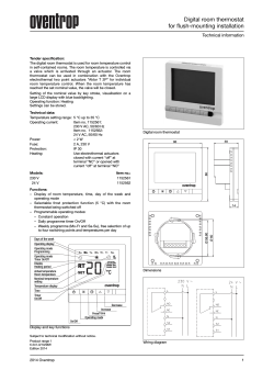


© Copyright 2026