
Document 415231
The Indian Roads Congress E-mail: [email protected]/[email protected] Volume 42 Founded : December 1934 IRC Website: www.irc.org.in Number 11 Contents November 2014 ISSN 0376-7256 Page 2 From the Editor’s Desk - “Does Acts and Verdict(s) framed for public good reach the common man urposefully? Enhancing Public Awareness” 3 Important Announcement Regarding International Conference of IRC Page 4 Technical Papers Performance Characteristics of Bituminous Mixes Modified by LDPE, HDPE and PP Granule Sunil Kumar Pal & by Vandana Tare 6 LRFD Approach for the Design of Reinforced Soil Walls: Comparative Study with the Convensional Methods by 13 A.D. Maskar & S.S. Bhosale Assessment of Suitability of Lime-Laterite Soils in the Construction of Road Base T. Ghosh by P.G. Bhattacharya 18 Kundan Meshram & R. Paul Pedestrian Safety in Urban Situation Er. V. Dinesh Kumar 23 Circular Issued by MoRT&H 24 Tender Notice, NH Tirunelveli 25 Tender Notice, NH Lucknow & Er. S. Satheesh Jamnagar House, Shahjahan Road, New Delhi - 110 011 Tel : Secretary General: +91 (11) 2338 6486 Sectt. : (11) 2338 5395, 2338 7140, 2338 4543, 2338 6274 Fax : +91 (11) 2338 1649 Kama Koti Marg, Sector 6, R.K. Puram New Delhi - 110 022 Tel : Secretary General : +91 (11) 2618 5303 Sectt. : (11) 2618 5273, 2617 1548, 2671 6778, 2618 5315, 2618 5319, Fax : +91 (11) 2618 3669 No part of this publication may be reproduced by any means without prior written permission from the Secretary General, IRC. Edited and Published by Shri S.S. Nahar on behalf of the Indian Roads Congress (IRC), New Delhi. The responsibility of the contents and the opinions expressed in Indian Highways is exclusively of the author/s concerned. IRC and the Editor disclaim responsibility and liability for any statement or opinion, originality of contents and of any copyright violations by the authors. The opinions expressed in the papers and contents published in the Indian Highways do not necessarily represent the views of the Editor or IRC. From the Editor’s Desk Does Acts and Verdict(s) framed for public good reach the common man purposefully? Enhancing Public Awareness Dear Readers, on account of the fact that once life is lost, the status quo ante cannot be restored as resurrection is beyond the capacity of man. This has a reference to the landmark Verdict dated 28.08.1989 of the Hon’ble Supreme Court of India (DB) in the matter of a writ petition in public • This decision shall be published in interest filed by a human right activist all journals reporting decisions of Pt. Parmanand Katara on the basis of this Court and adequate publicity newspaper report concerning the death highlighting these aspects should be of a scooterist, who was knocked down given by the national media as also by a speeding car. through the Doordarshan and the All (website: http://judis.nic.in/supremecourt/ India Radio. imgs1.aspx?filename=7839) • The Code of Medical Ethics 2. The Hon’ble Supreme Court had framed by the Medical Council was inter alia observed: approved on 23rd October, 1970. This only reveals an unfortunate • The Petitioner prayed for directions state of affairs where the decisions that every injured citizen brought are taken at the higher level good for medical treatment should intentioned and for public good instantaneously be given medical but unfortunately do not reach the aid to preserve life and thereafter the common man and it only remains a procedural criminal law should be text good to read and attractive to allowed to operate in order to avoid quote. negligent death. It is clear that there is no legal impediment for a medical 3. Following the aforesaid Supreme professional when he is called Court Verdict dated 28.08.1989, upon or requested to attend to an the Motor Vehicles Act (MVA) was injured person needing his medical amended in 1994, to make it mandatory assistance immediately. There is also on the part of both the driver/owner of no doubt that the effort to save the the vehicle to take the accident victim person should be the top priority not to the nearest doctor, and the doctor to only of the medical professional but treat the victim without waiting for any even of the police or any other citizen formalities. Section 134 of MVA states who happens to be connected with that driver and/or the person in-charge of the matter or who happens to notice the motor vehicle responsible for a road such an incident or a situation. accident is required to take all reasonable •On behalf of Union of India, it was steps to secure medical attention for the submitted that there are no provisions injured person by conveying him to the in the Indian Penal Code, Criminal nearest medical practitioner or hospital, Procedure Code, Motor Vehicles Act unless it is not practicable to do so on etc. which prevents Doctors from account of mob fury or any other reason promptly attending seriously injured beyond his control. Under Section 187 of persons and accident case before the MVA, whoever fails to comply with the arrival of Police and their taking into provisions of the clauses of Section 134, cognizance of such cases, preparation shall be punishable with imprisonment of F.I.R. and other formalities by the for a term which may extend to 3 months, Police. or with fine which may extend to Rs 500/• There can be no second opinion or with both. If it is the second time for that preservation of human life is of the person concerned, then the penalty is paramount importance. That is so harsher. The imprisonment may extend Place : New Delhi Dated : 21st October, 2014 2 to 6 months, or with fine which may extend to Rs.1,000/- or with both. 4. The basic question, whether the aforesaid Verdict/Government directives framed for helping accident victims could reach the common man actually remained unanswered. I experienced a jerk when a social periodic program named ‘Mumkin Hai’ anchored by one of the illustrious film stars was telecast on a TV channel, where the help to road accident victim was being discussed in detail. Possibly many of us may have viewed the program. It was disheartening to see that there was hardly anyone in the live telecast who was aware about the exemption from the legal formalities to the person providing such a help to the road accident victim pronounced by the highest Court of our land over 25 years ago. 5. The vital issue arises as to how to improve the implementation mechanism and what is the way forward to enhance public awareness. 6. In order to take into cognizance the challenges being faced in enhancing road safety and to pool our collective wisdom, the IRC in collaboration with the World Road Association; the World Bank; Japan International Cooperation Agency (JICA); International Road Federation and ADB is organizing an International Conference on “Road Safety Scenario in India and Way Forward” at Vigyan Bhavan, New Delhi on 29-30 November, 2014 (Saturday & Sunday). 7. I would like to appeal to all our fraternity to join in this endeavour and to share their experience and wisdom in this noble cause of saving avoidable loss of lives and injury due to road accidents and identify an implementable and sustainable Road Safety Action Plan. (S.S. Nahar) Secretary General E-mail: [email protected] INDIAN HIGHWAYS, November 2014 Important ANNOUNCEMENT ReScheduling of International Conference International Conference on “Road Safety Scenario in India and Way Forward” will now be held on 29 and 30 November, 2014 (Saturday and Sunday) at Vigyan Bhawan, New Delhi Organizers : Indian Roads Congress (IRC), Organizing Partners : World Road Association (Piarc) Japan International Co-operation Agency (JICA) International Road Federation The World Bank (Global Road Safety Facility) and Asian Development Bank (ADB) Who should attend : Govt./PSU/Autonomous Organization/NGO's/Emergency Medical Service Providers/Insurance Companies/Automobile Manufacturers/Traffic Police/Law Enforcing Agency/ Research & Academic Institutions/Transporter/Cargo Movers/Fleet Operators/Device Manufacturers, including all Individuals/Corporators directly or indirectly associated with the Cause of Road Safety. Tentative Themes of the Conference : Session 1:Overview of Traffic Rules & Regulations: Best Practices in the World (UK, Japan) Session 2: Road Safety Audit: Best Practices in the World Session 3:Overview of Urban & Non-Urban Traffic: Sustainable Way of Traffic Management including Medical Aid Session 4:Overview of Road Users’ Behaviour: Innovative Methods for Mass Awareness Movement Session 5: Review of Design of Vehicles : Innovative & Environmental Friendly Techniques Session 6: Panel Discussion & Suggested Way Forward – Short/Long Term. Focal Point: Shri Rahul V. Patil, Deputy Director (Technical), IRC (E-mail: [email protected] & [email protected]) Tel. 011 – 2671 6778. ● Opportunity available for Advertisers ● Opportunity available for Sponsorship ● Opportunity available for Registration (by Invitation only) For further details and enquiry for getting associated with the International Conference, please contact on E-mail: [email protected], Tel. No.: 2617 1548 and E-mail: [email protected], Tel. No.: 2338 7140. INDIAN HIGHWAYS, November 2014 3 Performance Characteristics of Bituminous Mixes Modified by LDPE, HDPE and PP Granule Vandana Tare*, Sunil Kumar Pal** and Kundan Meshram*** ABSTRACT Use of plastic waste in the construction of flexible pavement is gaining importance because of the several reasons. Utilize this type of non- biodegradable material in bituminous mixes substantially improving the stability or strength, fatigue life and other desirable properties, even under adverse water-logging conditions. Therefore, the life of the pavement surfacing course using the modified bitumen is also expected to increase substantially in comparison to the use of ordinary bitumen. Bitumen mixes do not perform up to the expectations for following reasons: 1. Bitumen does not have an affinity with water, which leads to pothole formation during and after rains. 2. With high air void ratio, top-down cracking is initiated, which makes the mix less durable. The present work has attempted to find solutions to these weaknesses of bitumen mix (DBM) by partial substitution/replacement of bitumen by granules of Low Density Polyethylene (LDPE), High Density Polyethylene (HDPE) and Poly-Propylene (PP). 1 INTRODUCTION The bituminous mixes have been performing as the standard material for road construction not only in India, but across the world. The performance of the pavement has scope for further improvement in various aspects. However, existing highway systems have been dealing with increased traffic volume, higher axle load and tyre pressure and extreme environmental impacts. It has been possible to improve the performance of bituminous mixes used in the surfacing course of pavements, with the help of various types of additives to bitumen such as polymers, rubber latex, crumb rubbertreated with some chemicals etc. Re-cycled plastic waste viz. LDPE, HDPE and PP may be useful in bituminous pavements, resulting in reduced permanent deformation in the form of rutting and reduced lowtemperature cracking of the pavement surfacing. It gives also greater durability and fatigue life has been reported in these modified mixes. varying percentage (6% to 14%) of plastic granules. 2. To compare the various properties of bitumen with and without additives. 3. Find out optimum percentages of plastic granules. 2OBJECTIVES OF THE STUDY This study has been done for following objectives: 1. To study the characteristics of Bituminous mix (DBM) with 3 EXPERIMENTAL PROGRAMME 3.1Materials Properties of aggregate are shown in Table 1. Table 1 Properties of Aggregate Impact Value (%) 17.27 Specific Gravity C.A – 2.82 F.A – 2.73 Filler -3.08 Properties of bitumen with and without Water Absorption (%) 1.57 Shape Test (%) 20.82 additives are given in Table 2. Table 2 Physical Properties of Conventional Bitumen and Modified Bitumen S. N. 1 2 3 4 Particular Bitumen without additives Bitumen with LDPE Bitumen with HDPE Bitumen with PP 4TEST RESULTS Bituminous mix samples were prepared with varying % of LDPE, HDPE and PP. These samples subjected to Marshall Test in the laboratory. Marshall Test results for bitumen are shown in Table 3. Penetration (mm) 67 at 25ºC 63 at 39ºC 30 at 45ºC 62 at 38ºC Ductility (cm) 91 85 60 34.4 The interpretation of the curves (shown in Figs. 1 to 6) is as follows: 1 Flow value 1. Flow value for LDPE lies in the standard range of MoRT&H from 2 to 4. The flow value is found to be minimum for 10 % additive. Softening Point (ºC) Specific Gravity 51ºC 1 65ºC 0.988 60ºC 0.993 65ºC 0.994 2. Flow value for HDPE comes out to be 4.85 to 3.47 which are slightly towards the higher side of the standard range of MoRT&H. 3. Flow value for PP comes ut to be 3.81 to 3.36 with additive at 10% to 14% which are within the standard range of MoRT&H from 2 to 4%. * Professor, SGSITS, Indore. ** Assistant Engineer, MPAKVN, Indore. *** Research Scholar, MANIT Bhopal E-mail: [email protected] 4 INDIAN HIGHWAYS, November 2014 TECHNICAL PAPERS Table 3 Marshall Test Results for 60/70 Grade of Bitumen S.N. Properties 1 2 3 4 OBC (%) Bulk Density (gm/cc) Air voids (%) Voids in mineral Aggregates (VMA in %) Voids filled with Bitumen (VFB in %) Stability (kN) Flow value (mm) 5 6 7 60/70 Grade of Bitumen 4.8 2.435 4.5 14.4 MoRT&H Specifications 4.5 minimum 3 to 5 13 to 15 74.8 65 to 75 12.35 3.4 9.0 minimum 2 to 4 Fig. 1 Granular % V/S Flow Fig. 5 Granular % V/S VMA PP, are within limits and is minimum for 6% additive. 3. A sinusoidal curve is obtained in case of HDPE and PP as additive and the value of Vv is found to be in the standard range of MoRT&H. 4 Voids in Mineral Aggregates (VMA) 1. The VMA is maximum in case of LDPE, while in HDPE and PP additives, we find almost same values of VMA with sinusoidal curves. 2. For LDPE, HDPE and PP additives, the value of VMA is found to be 15% to 19% which is higher than the standard value of 12.5% specified in MoRT&H. 5 Voids Filled with Bitumen (VFB) 1.VFB increases when the % of LDPE as additive increases from 6% to 10%, afterwards, with increase in additive, VFB decreases. 2. In case of HDPE and PP, sinusoidal curve is obtained and the values of VFB obtained, lie between the standard value specified in MoRT&H. 5 CONCLUSIONS Fig. 2 Granular % V/S Stability Fig. 6 Granular % V/S VFB 2Marshall’s Stability 1. Stability increases with increase in % of additives i.e. LDPE, HDPE and PP. The standard value specified in MoRT&H is 9.0 kN or 900 kg. Fig. 3 Granular % V/S Vv 2. The increase in stability is more up to 10% of additives, after which the growth rate becomes lower. 3. Maximum stability, observed with LDPE, HDPE and PP as additive, is 1626.67 kg, 1833.33 kg and 1900 kg respectively which is higher than MoRT&H’s specification. 3 Fig. 4 Granular % V/S Vb Percentage of Volume of Voids (Vv) 1. % Air voids obtained for LDPE are within limits and minimum for 10% additive. 2. % Air voids obtained for HDPE and INDIAN HIGHWAYS, November 2014 Based on the study following conclusions have been drawn: 1. With the replacement of 60/70 grade bitumen by granules of LDPE, HDPE and PP, the characteristics of bitumen mix in DBM are improved. 2. Stability increase with increase in percentage of additives i.e. LDPE, HDPE and PP. 3. Flow value for the mixes with PP, HDPE, and LDPE comes out to be within the standard range of MoRT&H from 2 to 4. 4. The % air void are within permissible limits set by MoRT&H, with the use of 10% LDPE, 6% HDPE and 6% PP granules in the mixes. 5. For LDPE, HDPE and PP additives, the value of voids in mineral aggregate (VMA) is found to be 15% to 19% which is higher than the standard value of 12.5% specified in MoRT&H, which may be due to the properties of additives and the additives are not properly absorbed in aggregates. 6. The optimum percentage of additives, in case of LPDE, HPDE and PP are recommended to be 10.70%, 8.7% and 8.7% respectively. 5 “LRFD APPROACH FOR THE DESIGN OF REINFORCED SOIL WALLS: COMPARATIVE STUDY WITH THE CONVENSIONAL METHODS” A.D. Maskar* and S.S. Bhosale** ABSTRACT In this paper, the detail of Load and Resistance Factor Design (LRFD) approach which is based on reliability concept for the design of Reinforced Soil (RS) walls is presented. For conventional methods i.e Allowable Stress Design (ASD) Method, the factor of safety is applied only for the resistance and loads are considered without variations. In LRFD method, the factor of safety is applied for both load and resistance. Due to availability of large statistical data and economy, this method is preferred for the design of the RS walls. An attempt is made to solve a numerical example of geosynthetic RS walls due to soil self-weight plus permanent uniform surcharge. The example is solved using LRFD as well as other conventional methods (ASD) viz. FHWA, Modified Rankine, NCMA and B.S Code Methods and the results of the LRFD methods are compared with conventional design methods and concluding remarks are presented. The various equations have been obtained based on various curves plotted by using ASD and LRFD approaches. These equations reveal if FOS against tensile rupture is known for any RS wall having 7m height and same properties and environmental conditions as mentioned in current study then FOS against pullout failure and pullout capacity can be computed for these walls without performing actual pullout test. 1 INTRODUCTION 1.1Preamble In traditionally, the Reinforced Soil (RS) walls are designed using Allowable Stress Design (ASD) approach. As RS wall being geotechnical structure, a lot of uncertainties have been involved in geotechnical parameters and hence there is ample scope of an economical design of the RS wall. Presently there are guidelines for Load and Resistance Factor Design (LRFD) approach which is more economical than the ASD approaches due to proper FS. RS walls can be designed for both external and internal stability considerations; a) External stability consideration: Sliding, Bearing capacity, overturning about the toe of the wall etc. b) Internal stability consideration: Tensile overstress, Pullout Resistance, Facing connection overstress etc. 1.2Conventional Methods/Allowable Stress Design (ASD) Methods There are various conventional methods through which the RS walls can be analysed (Koerner, 2001) a) A Modified Rankine approach. b) The Federal Highway Administration approach (FHWA) c) The National Concrete Masonry Association approach (NCMA) d) BS Code Method BS 8006:1995. Fundamental equation governing ASD approach is given by, ... (1) Rn/FS ≥ ΣQi Where, Rn = Nominal Resistance, ΣQi = Sum of all Loads, FS = Factor of Safety. Graphically, the ASD approach can be illustrated as shown in Fig. 1 which isone of the principal limitation of ASD approach, wherein the values of Q and Rn are assumed to be unique so that they have a probability of occurrence as unity. Fig. 1 ASD Design Approach (FHWA 2001) 1.3Limitations of ASD Approach Does not adequately account for the variability of loads and resistances. The FS is applied only to resistance and loads are considered without variation. Does not represent a reasonable measure of strength which is more fundamental measures of resistance than the allowable stress. Selection of the FS is subjective and does not provide a measure of reality in terms of probability of failure. 2Load and Resistance Factor Design (LRFD) Approach In LRFD approach, the resistance side is multiplied by a statistically-based resistance factor φ whose value is usually less than one which accounts for the various factors like weaker foundation soils than expected, poor construction of the RS wall sand its materials such as earth, geogrids or steel strips that may not completely satisfy the requirements in the specifications. The load components on the right side are multiplied by their respective statistically based load factors, γi, whose values are usually greater than one. Because the load effect at a particular limit state involves a combination of different load types, the load factors differ in magnitude for the various load types. Therefore, the load effects can be represented by a summation of γi Qi products. If the * Amol D. Maskar, Research Scholar, E-mail: [email protected]. ** Sukhanand S. Bhosale, Professor, E-mail: [email protected] (Department of Civil Engineering, College of Engineering, Pune) 6 INDIAN HIGHWAYS, November 2014 TECHNICAL PAPERS nominal resistance is given by Rn, then the safety criterion can be written as, Rr = φ Rn ≥ Σηiγi Qi ... (2) Where, φ = Statistically-based resistance factor (dimensionless), Rn = Nominal resistance, ηi = Load modifier to account for effects of ductility, redundancy and operational importance (dimensionless), γi = Statisticallybased load factor (dimensionless), Qi = Load effect. Because of the above equation involves both load and resistance factors, the design method is called Load and Resistance Factor Design (LRFD) method. For a satisfactory design, the factored nominal resistance should equal or exceed the sum of the factored load effects for a particular limit state. Load and resistance factors are chosen so that in the highly improbable event that the nominal resistance of the RS wall elements is overestimated and at the same time the loads are under estimated. There is a reasonably high probability that the actual resistance of the RS wall elements should still be large to support the loads. Fig. 2 implies that safety margin for ASD approach is more as compared to that of the LRFD approach due to unfactored loads and resistance in ASD approach. Therefore, LRFD approach is more economical as compared to ASD approach. Fig. 2 Combination of ASD and LRFD Approach 2.1Problem Formulation Bathurstet. al. (2008) developed both load and resistance models for the design of the RS walls. Those load & resistance factors can be estimated by collecting data from laboratory and field pullout tests for RS wall having steel strips as a reinforcing material. Thus, from the another literatures, it is found that no attempt has been made for LRFD calibration of RS wall using geogrid as a reinforcement and soil self weight plus permanent uniform surcharge as a loading condition. Hence, it is necessary to design RS walls using LRFD approach and compared the same with ASD approaches. 2.2Aim and Objectives Review of Load and Resistance Factors Design (LRFD) approach for the design of RS walls and its results are compared with conventional design methods (ASD methods) viz. FHWA, Modified Rankine, NCMA and B.S Code Methods and certain conclusions are drawn. 3LRFD Calibration of Pullout Limit Test The LRFD calibration of RS wall using geogrid as a reinforcement and soil self weight plus permanent uniform surcharge as a loading condition is used in the current study. Its limit state function for pullout failure is given by, φPC – γQTmax ≥ 0 ... (3) Where, Pc = Nominal calculated pullout capacity (Rn), Tmax = Nominal calculated maximum reinforcement load (Qn), φ = corresponding resistance factor, γQ = corresponding load factor applicable to internal stability of RS wall. 3.1AASHTO Modified Simplified Method for Load Models The maximum reinforcement load (Tmax) using AASHTO Simplified Method is computed as (For Self wt + uniform surcharge), Tmax = λ Sv Kr σ v + λ Sv Kr q gives, Tmax = λ Sv Krγb (Z + S) ... (4) Where, λ = Bias factor (for current AASHTO INDIAN HIGHWAYS, November 2014 = 1, for Modified AASHTO = 0.30 & 0.15), Sv = Vertical spacing of the reinforcement layer, Kr = Lateral earth pressure coefficient (1.7 Ka to 1.2 Ka for Steel strips and Ka for geosynthetic), σ v = Normal stress due to self-weight of the backfill (γb Z) and equivalent height of uniform surcharge pressure (S = q/ γb), γb = Bulk unit weight of soil, z = Depth below crest of the wall, q = Uniform distributed surcharge. Reinforcement Load Data and Bias Statistics The reinforcement load data for 7 m high RS walls containing surcharge load (q) varying from 10 kPa to 30 kPa and angle of internal friction (φ) for backfill varying from 28º to 36º, is available from different case studies reported by Allen et al. (2002), Miyata and Bathurst (2007a,b) and Bathurst et al. (2008b). This data is used to compute maximum tensile load Tmax (Calculated load) in the geogrid at each layer using Eq (4). By knowing measured load (Q), the load bias can be computed at each layer of geogrids using equation given by Bathurst et al (2008). The constant coefficient λis called bias factor which introduced in Eq(4). When λ = 1, the current AASHTO Simplified Method is used to compute maximum tensile load in each geogrid layer for φ backfill whereas, when λ = 0.3 and 0.15,the Modified AASHTO Simplified Method is used to compute maximum tensile load in each geogrid layer for φ and C-φ backfill soil cases, respectively. 3.1.1 Current AASHTO Simplified Method (λ = 1) Fig. 3 shows measured versus calculated (Tmax) load values using the current AASHTO Simplified Method for all wall cases in the database used in this study with cohesion less (φ) backfill. It shows none of the data points fall above the 1:1 correspondence line. In this case, the calculated load values 7 TECHNICAL PAPERS are an order of magnitude higher than the measured value. As the mean of load bias values is μQ = 0.68, hence, it concludes that measured load values (Q) are 68% of the calculated load values (Tmax). Fig. 3 Measured vs Calculated Load values for λ = 1 based on calculated Tmax into two or more groups, or filtering the data (Bathurst et.al. 2008). However, this will result in different resistance factors for different load ranges and thus complicates design. The strategy ultimately adopted in the current study to minimize load bias dependency was to remove selected bias values. After many attempts, the best filter criterion for c-φ soil wall cases is to remove all load bias values corresponding to calculated Tmax < 0.5 kN/m (Bathurst et.al. 2008) as shown in Fig 5. 3.1.2 Modified AASHTO Simplified Method (λ = 0.30) Fig. 4 shows, the current AASHTO Simplified Model for calculation of reinforcement loads for operational (prepared) conditions. This model is very poor for frictional (φ) backfill because the current AASHTO simplified model over-estimates the loads by a factor of three. This deficiency can be corrected empirically by using λ = 0.30 in Eq. 4 to compute Tmax. Also,the data points fall above and below of the 1:1 correspondence line. For this case, mean bias value nearly equal to 1 whereas COV = 0.28. Fig. 4 Measured vs Calculated Load for λ = 0.30 3.1.3 Modified AASHTO Method (λ = 0.15) In order to extend the utility of the modified Simplified Method to (c-φ) backfill, a complication that arises when all data points are considered is an undesirable dependency between load bias values XQ and calculated load Tmax. This deficiency can be corrected by dividing the load data 8 Fig. 5 Measured vs Calculated Load for λ = 0.15 3.2Modified AASHTO Simplified Method for Pullout Capacity Models According to AASHTO (2010) and FHWA (2009) the ultimate pullout capacity for sheet geosynthetics (geotextiles and geogrids) is estimated as, Pc = 2 (F*α) σv Le ... (5) An alternative expression that used in practice is (Huang and Bathurst 2009), Pc = 2 (Ψ tan φ) σv Le ... (6) Where, Le = anchorage length, F* and α = dimensionless parameters, Ψ = tan φsg/tan φ = dimensionless efficiency factor, φsg = peak geosynthetic-soil interface friction angle = δ. In the FHWA document, the following default values are recommended: αis 0.8 for geogrids and 0.6 for geotextiles, whereas F*=2/3 tan φ (Huang et.al 2009). Pullout Test Database:- The pullout resistance data for 7 m high RE walls containing surcharge load (q) varying from 15 kPa to 55 kPa and angle of internal friction (φ) for backfill varying from 280 to 400, is available from different case studies reported by Huang and Bathurst (2009). The tests were carried out in general conformity with ASTM D 6706 (2007). As reported by Huang et.al (2009), there are five models used to measure pullout capacity of geogrid in RS walls which are listed in Table 1. Out of these models, Model 1 corresponds to the case where a single (average) value of F*α is computed from a set of pullout tests. Model 4 uses a bilinear approximation to the efficiency factor Ψ. As demonstrated by Huang and Bathurst, both models have strong bias dependencies with normal stress and therefore they are omitted from the current study. Therefore, model 2, model 3 and model 5 are used in the current study. Table 1 Pullout Models, their Descriptions and their use in the Current Study Pullout Model Description Model- 1 Average measured F*α First-order approximation to measured F*α FHWA method with default values F*α = 0.8 x (2/3) tan φs Bi-linear model Model- 2 Model- 3 Model- 4 Model- 5 3.2.1 Non-linear model Use in Current Study No Yes Yes No Yes Model – 2 First-order approximation to measured F*α: A back-calculated values of F*α using Eq. 5 are determined from a set of tests performed on the same soil-geogrid combination at different normal stresses. Fig. 6 shows that measured (Pm) versus predicted (Pc) resistance INDIAN HIGHWAYS, November 2014 TECHNICAL PAPERS values plot tightly around the 1:1 correspondence line having mean and COV value of 1.03 and 0.13 respectively. 3.2.3 Model – 5: Non-linear model The general form of the non-linear pullout model proposed by Huang and Bathurst (2009) is given by, Pcorr = β (Pc)1+k = β (2 σv Le F* α)1+k ... (7) Where, dimension-dependent terms β and (1 + k) are equal to 5.51 and 0.629 when pullout capacity is computed in units of kN/m (Bathurst 2009). Thus, for the model 5, the mean is 1.12 and COV is 0.50. From the above analytical investigation, the results of mean and Coefficient of Variation (COV) for different Load and pullout capacity models are tabulated as shown in Table 2. Table 2 Summary of Load bias statistics (XQ) Parameter Fig. 6 Measured vs Calculated Pullout Resistance values for Model 2 3.2.2 SOIL TYPE Frictional (φ- Soil) Current Model λ = 1.0 Model – 3 FHWA method with default values F*α =0. 8x (2/3) tan φs Model 3 corresponds to the current FHWA (2009) geogrid pullout model. However, unlike Model 2, soil-geogrid pullout tests are not carried out. Rather, the default value α = 0.8 is used and F* is computed using φ of the soil. Fig.7 shows, measured versus predicted pullout resistance values. Most of the data fall above the 1:1 correspondence line and the bias mean is μR = 1.20. Hence, Model 3 underestimates the pullout capacity. (c-φ Soil) Modified Model λ = 0.30 Modified Model λ = 0.15 n (Number of data points) 50 50 50 μQ (mean) 0.68 1.02 1.08 COVQ 0.17 0.28 0.67 4 CASE STUDY To incorporate the effect of Load and Resistance Factors in design of RS wall, a numeric example has been solved using LRFD approach which was already solved by Koerner et.al (2001) using different ASD approaches. Considering a RS wall as shown in Fig. 8 having following properties, Fig. 8 Measured vs Calc Pullout for Model 5 Table 3 Bias Statistics for Different Pullout Capacity Model Types Model Fig. 7 Measured vs Calculated Pullout Resistance values for Model 3 Description Bias Statistics Mean μR COVR 2 First-order approximation to measured F*α 1.03 0.13 3 FHWA method with default values (F*α = 0.8 x (2/3) tan φ) 1.20 0.59 5 Non- linear model 1.12 0.50 Table 4 Computed Resistance Factor φ for Pf = 0.01 (β = 2.33) and selected load factors γQ Pullout Models Load Factors Γq Current Load Model (λ = 1) Φ-Soil MODEL-2 MEAN μR = 1.03 COVR = 0.13 1 1.35 1.75 2 INDIAN HIGHWAYS, November 2014 1.18 1.6 2.07 2.37 Resistance Factor (Φ) Modified Aashto Load Model (λ = 0.30) (λ = 0.15) Φ - Soil C- Φ- Soil 0.49 0.28 0.58 0.38 1.03 0.5 1.18 0.57 9 TECHNICAL PAPERS Load Factors Γq Pullout Models Resistance Factor (Φ) Modified Aashto Load Model (λ = 0.30) (λ = 0.15) Φ - Soil C- Φ- Soil 0.43 0.34 0.56 0.46 0.75 0.57 0.88 0.63 0.33 0.46 0.43 0.62 0.58 0.8 0.66 0.91 Current Load Model (λ = 1) Φ-Soil MODEL-3 COVR = 0.59 MODEL-5 1.29 1.73 2.28 2.59 0.87 1.19 1.55 1.76 1 1.35 1.75 2 1 1.35 1.75 2 MEAN μR = 1.20 MEAN μR = 1.12 COVR = 0.50 Table 5 Summary of Recommended Resistance Factor Values for β = 2.33 and γQ = 1.35 using Current and Modified AASHTO Simplified Method Resistance (Pullout) Model Model- 2 Model- 3 Model- 5 Current AASHTO Resistance Factor φ Load Models Modified AASHTO λ=1 φ - SOIL 1.00* 1.00* 1.00* λ = 0.30 φ - SOIL 0.58 0.56 0.43 λ = 0.15 c-φ SOIL 0.38 0.46 0.62 5RESULTS AND DISCUSSION 5.1External Stability Considerations In the Modified Rankine’s approach, the frictional force is computed by taking into account only the weight of reinforced soil mass i.e. it neglects surcharge effect for conservative side. Hence, it has less frictional resistance thus FOS is less (2.07) for this method. Table 6 Comparisons of FS for External Stability EXTERNAL STABILITY CONSIDERATION Fig. 9 Typical RE wall Having Modular Facing Block Height of wall (H) = 7 m, Length of wall (L) = 5 m, Surcharge (q) = 15 kPa, Reinforced soil properties: φr = 320, γr = 18 kN/m3 Backfill properties: φb = 30º, γb = 17 kN/m3 Foundation soil properties: φf = 30º, γf = 17 kN/m3 10 Sr. No. STABILITY CONSIDERATION (FOS) M.R FHWA NCMA B.S CODE LRFD 01 FS against sliding (1.5) 2.07 2.11 2.87 2.15 1.70 02 FS against capacity 3.59 3.66 5.53 3.17 2.25 03 FS against overturning ( ≥ 2.0) 3.63 N.A 4.93 5.52 3.57 In BS Code approach, the frictional coefficient is taken approximately equal to 1/3 to 2/3 of tan φ where, φ is angle of internal friction hence, more FOS (2.15) as compared to Modified Rankine’s approach. In LRFD approach, the resistance is reduced whereas the load effect is increase as explained earlier. Therefore, it has least factor of safety than other ASD approaches (1.70). The coefficient of friction in NCMA approach depends upon types of the soil which controls the sliding (reinforced, drainage and foundation) as given by Koerner et.al. 2001. Hence, frictional resistance of NCMA approach is more as compared to FHWA and Modified Rankines INDIAN HIGHWAYS, November 2014 TECHNICAL PAPERS approaches, hence more FOS (2.87). In Modified Rankine approach, overturning moment can be computed by adding moments due to earth pressure and surcharge loading for safer side. Table 7 Comparison of FS for External Stability Consideration (Eccentricity Consideration) External Stability Consideration Stability Consideration M.R FHWA NCMA B.S CODE LRFD Eccentricity (m) ( e ≤ B/6) 0.64 0.63 0.42 0.64 0.70 Also, total vertical load (ΣW) is the sum of weight of soil mass and surcharge loading therefore eccentricity is maximum and also equal to BS Code approach because it is attributed to the ratio of difference between resisting moment and overturning moment to total vertical load. Thus, the eccentricity is given by, e = (B/2) - x, hence e is more (0.64m) as compared to Modified Rankine approach. In LRFD approach, the location of resultant is at middle half of the base. Therefore, gets decrease and eccentricity increase (0.70 m). 5.2Internal Stability Considerations 5.2.1 Tensile Failure Fig. 10 Factor of Safety Against Tensile Rupture In the Modified Rankine approach, the vertical stress (σv) is due to self weight of reinforced soil and surcharge effect, hence it is more. As the design strength (Tdes) is a function of vertical stress, it is also more and thus FOS = is less. In BS Code approach, the maximum vertical stress (σvmax) is given by sum of direct and bending stress which is less and hence FOS is more as compared to Modified Rankine’s approach. In LRFD approach, the empirical adjustments are made by using bias factor λ to the tensile load models to match measured reinforcement loads in RS walls under operational conditions. Therefore, incase of LRFD approach FOS is most as compared to other ASD approaches as shown in Fig 1. The active earth pressure distribution on RS wall is triangular in nature having zero pressure at top and linearly increases to maximum at bottom. Therefore, the vertical spacing of geogrids is minimum at bottom and gets increases from bottom to top. As the tensile force is a function of vertical spacing of geogrid layers, it is maximum at top gets decreases with depth of the wall. Therefore, the FOS is also more at the top of the wall and gets decrease continuously with depth of the wall. The trends of FOS for all five methods are approximately same whereas trend of Modified Rankine, FHWA and NCMA approach matches with each other as shown in Fig 10. The FOS for LRFD approach is more as compared to other approaches may be because in LRFD approach, the maximum tensile force gets decrease due to bias factor λ for Modified Simplified AASHTO method for Load model. 5.2.2 Pullout Failure In Modified Rankine approach, the pullout capacity (Pc) can be computed by assuming interaction coefficient and coverage ratio, due to this pullout capacity gets decrease and hence FOS also gets decrease. In BS Code INDIAN HIGHWAYS, November 2014 approach, to compute Pc, the average stress at resistive zone is assumed instead of maximum stress and hence FOS is more as compared to Modified Rankine approach. In LRFD approach, to compute pullout capacity, five deterministic models are used. The resistance factor φ = 0.58 is taken to compute pullout capacity in the current study from model 2 which requires actual laboratory pullout tests. Hence, for LRFD approach, FOS may be least for all layers of RS walls as compared to ASD approaches. Fig. 11 Factor of Safety against Pullout Failure The Rankine’s failure plane is inclined which makes an angle of (45+φ/2) with horizontal hence effective length is lesser at top and gets increase from top to bottom. As pullout capacity is the function of effective length, pullout capacity as well as FOS is less at top and more at bottom as shown in Figs. 11 and 12 shows the graph between FOS against pullout failure on normal scale versus FOS against tensile rupture on semi-log scale for all five approaches together. Fig. 12 Factor of Safety Against Pullout Failure vs. Factor of Safety against Tensile Rupture Fig. 12, reveals that the trend of Modified Rankine, FHWA and NCMA 11 TECHNICAL PAPERS approaches are approximately parallel to each other. On the other hand, the trend of BS Code and LRFD approaches are approximately parallel to each other. The equations of the trendlines for various approaches and their R2 values are tabulated in Table 8. Table 8 Equations of the Trend Lines and their R2 Values for Various Approaches Design Approach Equation of Trend Lines R2 Value Modified Rankine FSPu = -33.6 ln(FSTR) + 37.47 0.940 FHWA FSPu = -31.9 ln(FSTR) + 39.02 0.906 NCMA FSPu = -47.0 ln(FSTR) + 54.26 0.906 BS CODE FSPu = -14.1 ln(FSTR) + 28.16 0.947 LRFD FSPu = -13.0 ln(FSTR) + 30.46 0.977 Table 8 consists of various equations which reveals that that if FS against tensile rupture is known for any RS wall having 7 m height and same properties and environmental conditions as mentioned in current study then FS against pullout failure can be computed for these walls. In the Table 8, the equations are used only for that RS walls which has same dimensions, same material properties and same environmental conditions as that of RS wall used in present study. Hence, these equations are not universal equations but can be converted into universal equations by further work. 6 CONCLUSIONS 1. The FS against Pullout failure varying from 35.20 to 22.44. 2. Depending on the reinforced soil type (frictional & cohesivefrictional) and the pullout model adopted, the resistance factor (φ) varies in the range of 0.38 to 0.62. While these values are lower than φ = 0.90 recommended by AASHTO. 3. An important practical benefit of using Model 2 (First-order approximation to measured F*α) with actual laboratory pullout data over the default Model 3 (FHWA method with default values F*α = 0.8 x (2/3) tan φs) and non-linear Model 5 is that the Model 2 allows a higher resistance factor (φ) to be used for design; the result is shorter reinforcement lengths and hence more cost-effective wall design outcomes. 4. New generated equations reveals that that if FOS against tensile rupture is known then FOS against pullout failure can be computed. 5. Also the value of F*α is obtained without performing actual pullout test. 6. As pullout test is costlier and difficult to performed so current study gives various equations and from which FS against pullout failure is obtained without performing actual pullout test. 7 ACKNOWLEDGEMENT The M.Tech dissertation work is carried out at Department of Civil Engineering, College of Engineering, Pune during academic year 2011-12. Director, COEP has acknowledged giving permission for publishing this work. ANNOUNCEMENT Sales Centre of IRC is being operational at Bhabani Bhavan, Kolkata (West Bengal) from 26th September, 2014. The endeavor of IRC is to enhance its reach to the Engineering Fraternity. The esteem members of IRC are requested to take advantage of this new initiative. The contact address of Sales Centre of IRC is Bhabani Bhavan, New Building, 7th Floor, Kolkata-700 027 (West Bengal), Tel: 09874462649 E-mail: [email protected] OBITUARY The Indian Roads Congress express their profound sorrow on the sad demise of Late Shri Suresh Mukhdekar, Resident of 1-2-5-35, Uday Nagar, Nanded (M.S.). He was an active member of the Indian Roads Congress. May his soul rest in peace. 12 INDIAN HIGHWAYS, November 2014 Assessment of Suitability of Lime-Laterite Soils in the Construction of Road Base P.G. Bhattacharya*, T. Ghosh** and R. Paul*** ABSTRACT Highway pavements need good quality paving materials having adequate strength and durability characteristics. With petroleum prices rising sharply, bitumen is no longer a cheap material and therefore bituminous macadam and other bituminous materials cannot be considered as economical road bases at present. But highway activities have increased manifolds in recent times due to rapid industrialization and urbanization. As a result, quality paving materials have really become scarce and costly. Under the circumstances use of locally available indigenous materials after suitable treatment or otherwise, is the only solution to meet the growing demand of road construction and replace the costly paving materials being used. The suitability of laterite soils for use as road bases after treatment with lime and coconut fibre is considered fruitful in this regard. A good road base made up of bound material should have adequate flexural fatigue strength and durability, particularly when the material is applied in the upper layers of the pavement. Addition of lime in favourable climate in small amounts, 3 to 7 percent by weight, to reactive soils brings about a decrease in density, a reduction in plasticity, an improvement in workability and an increase in soil strength. The pozzolanic reactions take place between lime and soil silica or alumina and form various cementing agents, primarily silicates and aluminates of calcium responsible for development of strength. 1 INTRODUCTION Laterite soils are essentially products of tropical and sub-tropical weathering. The chemical composition and chemical characteristics of these products are influenced by the degree of weathering to which the parent material has been subjected. Laterites are products of intense sub-aerial rock weathering, whose iron and aluminium content is higher and silica content is lower than in merely kaolinised parent rocks. They consist predominantly of kaolinite, goethite, hematite, gibbsite and quartz. A laterite profile comprises all stages from parent rock to the surface and therefore laterite soils cover a wide range of materials, from earthy to rocky. They are commonly found as reddish pedogenic surface deposits and are popularly known as ‘red tropical soils’. The location and distribution of laterite materials have been associated with temperature and rainfall conditions characterizing the earth’s surface between latitudes 35ºN and 35ºS (1). Of this, nearly one-third of the total land surface of the earth is contained within the huge belt bounded by the tropics of cancer and capricorn. ‘Red tropical soils’ are dominant feature of the landscape within this area (2). In India, the coastal part and its adjoining interior are areas of known laterite soil occurrence and exhibits distinctive distribution of these soils. 2LATERITE FORMATION Laterite soils are formed in humid tropical and sub-tropical areas of South America, Africa, India, Indonesia and Australia. Essentially, they are products under certain weathering conditions. Tropical weathering and laterisation involve chemical and physico-chemical alteration and/ or transformation of primary rockforming minerals into materials rich in clay minerals and laterite constituents that is iron, aluminium, titanium and manganese. High content of laterite constituents in relation to other constituents is the important feature of all laterite soils. There are three stages in the process of weathering and laterisation, the first stage called decomposition, is characterised by physico-chemical break-down of primary minerals whereby constituent elements such as SiO2, Al2O3, Fe2O3, CaO, MgO, K2O, Na2O etc., are released and appear in simple ionic forms (3). Physical weathering involves fragmentation of parent rocks into end products consisting of angular bocks, cobbles, gravel, sand, silt and even to claysized rock flour as a result of periodical temperature changes, erosional forces, and the disintegrating action of plants and animals. Chemical weathering, on the other hand, is the decomposition of rock and formation of new minerals as a result of action of water, air, organic acid etc., that enter into chemical reactions with the primary minerals. The predominance of chemical or physical weathering depends on climatic conditions, mainly rainfall and temperature (4) and wetter the area, more intense is the weathering. Laterisation is the second stage, which involves leaching under appropriate drainage conditions, of combined silica and bases and the relative accumulation or enrichment of oxides and hydroxides of sesquioxides, mainly Al2O3 and TiO2 from external sources. Leaching is the most important phenomenon in laterite soil forming process; the percolating water is the most active agent in soil profile development (3, 5, 6). The soluble constituents are released by the hydrolyzing processes and removed by repeated flushing by rain water resulting in weathering reactions to proceed towards completion. According to Ahn(7), chlorides and sulphates, being very soluble are quickly removed in * Emeritus Professor, ** Assistant Professor, *** Assistant Professor, E-mail: [email protected] (Department of Civil Engineering, Hooghly Engineering & Technology College, Hooghly, W.B.) INDIAN HIGHWAYS, November 2014 13 TECHNICAL PAPERS the first stage of weathering and then calcium, sodium, magnesium, and potassium with subsequent removal of combined silica from silicates. The most resistant compound to leaching are the sesquioxides of iron and aluminium, Fe2O3 and Al2O3. Therefore slightly to moderately leached soils may lose all the mobile elements in the first and the second stages but retain all or most of the combined silica and sesquioxides. In extreme weathering condition, silica is removed more and with further weathering, leaching and translocation, the quantity of silica is reduced and the proportion of iron and aluminium sesquioxides is increased. Thus, more the leaching, more is the probability of weathering and laterisation towards formation of true laterites. The third stage is the partial or complete dehydration and sometimes hardening of the sesquioxides-rich materials and secondary minerals. In the process of hydration colloidal hydrated iron oxides lose water resulting in concentration and crystallisation of the amorphous iron colloids into dense crystalline iron minerals in the sequence : Limonite, goethite, and goethite with hematite to hematite as observed by Hamilton (8) and other researchers. 3LITERATURE REVIEW Depending on the hardening property, Buchanan (9) was the first to introduce the term laterite and define it as a ferruginous, vesicular, unstratified, porous material with yellow ochres due to high iron content occurring in Malabar, India. The freshly dug material was soft enough to be readily cut into brick block with an iron instrument but rapidly hardened on exposure to air. Wooltorton (10) describes it as “a very hard homogenous vesicular massive clinker like material found in hilly tropical countries, in which the structural framework is of red hydrated ferric oxides and the vesicular in fill is 14 of soft aluminium oxides of a yellowish colour; or a similar profile of softer material which hardens on extraction and exposure.” Fermor (11) defines various forms of laterites on the basis of the relative contents of the so-called laterite constituents (Fe, Al, Ti and Mn) in relation to Silica. Winterkorn and Chandrasekharan (12) recongnised the presence of iron in lateritic soils as the most important factor in influencing the engineering properties of these soils. Alexander and Cady (13) summerised the physical, chemical and morphological concepts of laterites proposed by various researchers in the following lines: “Laterite is a highly weathered material, rich in secondary oxides of iron, aluminium or both. It is nearly void of bases and primary silicates, but it may contain large amount of quartz and kaolinite. It is either hard or capable of hardening on exposure to wetting and drying. Remillon (14) has named the zone of leaching as horizon A, the zone of accumulation as horizon B, the zone of weathering as C and the sound parent rock D. The other method of naming is according to the morphological characteristics by which soils are identified. Thus horizon A represents the generally dark humus stained top soil, B2 the laterite horizon of iron and alumina crusts, B1 the zone of mottling having evidence of sesquioxides enrichment, C the pallid or leached zone and D the sound parent rock. Rao, Datta and Neyogi(15) made a study of laterite soils around Kharagpur, India under different land use with respect to their mineralogical composition and some chemical and physio-chemical aspects. They identified two distinct soil horizons: (a) laterite hard crust and (b) laterite soil. 4 ASSESSMENT OF SUITABILITY Suitability of a material for engineering purposes can be tested on the basis of strength and durability. The direct way to recognize whether a soil for use in pavement layers is suitable or unsuitable or can be made suitable by treatment is possible by studying the various strength characteristics. The laterite soils vide Table 1 for physical properties; have two distinct soil horizons, the laterite hard crust and the underlying mottled zone. The air-dried soil without any treatment gave C.B.R. values under modified AASHTO compaction as low as 3.42 to 3.50, which further decreased on soaking. Five percent addition of hydrated lime, containing nearly 64 percent calcium oxide increased the values 10 times or so and 4 days soaking further improved the results. This, therefore, indicated that the soils were limereactive in nature and there was scope for detailed investigation of the material-strength based on compaction, curing and mix proportion. It has been almost universally accepted that addition of lime in favourable climate in small amounts, 3 to 7 percent by weight to reactive soils produces a marked improvement in the engineering properties (16, 18). This brings about a reduction in plasticity, an improvement in workability and an increase in soil strength. The degree to which the lime will react with soil, however, depends on such variables as the quantity of lime, soil type, the compaction, and the length of time the lime-soil mixtures are cured and also the curing temperature of accelerated curing. By accelerated curing it has been meant that curing has been done in oven at controlled temperature. Anday (22) and Thompson (23) both cured lime-soil specimens at 50ºC to obtain very quick response in development of strength. This was taken as the guidance for selecting 50ºC as the limiting temperature. The laterite materials as used, having found to respond favourably to lime treatment on preliminary investigation giving increased C.B.R., were subjected to INDIAN HIGHWAYS, November 2014 TECHNICAL PAPERS unconfined compression to determine quantitatively the beneficial effects of the treatment by obtaining strengthdensity relationship, by working out optimum composition of the mix, and by comparing normal laboratory moist curing with accelerated oven curing. Compaction is commonly used to improve the strength of the pavement layers, bound or unbound. The usual compaction variables are water content, dry density and compacting work. For compaction, dry of optimum and also the optimum dry density, is a function of both water content and compactive work, and for compaction wet of optimum, it is mainly governed by water content (19). However, whatever be the compaction variables, dry density is finally attained has become the basis of comparison (20). Compaction was identified at three levels, light, medium and heavy. Standard proctor compaction density was taken as a measure of light compaction, modified AASHTO compaction density as a heavy, and the mean of the two, approximated medium compaction. Specimens of different densities could be obtained by varying the moulding water at constant compactive effort, or by applying different compactive effort at the same moulding water, or by compacting pre- determined weight of wet materials to constant volume, weight being determined on the basis of desired moisture content and dry unit weight. It is fairly common knowledge that the strength of a material particularly a cemented material is dependent to a great extent on its dry density. Whatever be the factors contributing to dry density, dry density is the ultimate state attained by a specimen in a compaction phenomenon. Therefore statistical correlation between strength and density of compacted specimens of lime-laterite mixtures, if available, should yield a relationship taking into account other factors associated with compaction giving a relationship general in nature between strength and density. Strength is however a function of lime dose also. For this reasons specimens were prepared at different dry densities, low, medium and high, at each of the lime per cent added, 2.5, 5.0 and 7.5 by weight of air-dry soil. The samples were cured in oven at 50ºC ± 1ºC for 3 days(16). Regression relationships were obtained for each of the lime per cents and optimum percentage of lime for maximum strength benefit was worked out(16). Another four groups of specimens prepared with optimum, 5 per cents of lime, but of different densities and classified on the basis of four moist curing periods of 15day, 30-day, 45-day and 60-day were tested in unconfined compression and the results correlated to develop four prediction equations corresponding to four curing periods. The number of days of moist curing equivalent to 3-day oven curing at 50ºC were worked out by comparing these relationships with that of oven cured specimens with 5 per cents of lime. The strengthdensity relationships for four moist curing periods were used to obtain compressive strength at different days of curing and at different densities. Finally multiple regression analysis was made to develop prediction equation for unconfined compressive strength on dry density and number of days of moist curing. The particle size distribution of lateritic soil is given in Table: 2. The unconfined compression test results gave considerable strength increase. 7-day UCS values for cement stabilized silty clay (L.L = 74%, PL = 28%) compared with lime laterite soils are given below in Table 1, for 5%of stabilizer (24) which shows that Lime laterite soil with 5% lime yield better strength at Modified Proctor compaction. Table 1. 7-day UCS Values of Lime Laterite Soil and Cement Soil Mixtures of Different Densities % of Stabilizer Stabilizer 5% UCS Value (MPa) Standard Modified Lime 0.58 2.15 Cement 1.10 2.10 But a pavement is made up of layers of different materials and when the overlying layers have higher moduli of elasticity than the underlying layers, tensile stresses are developed at the interfaces of the stiff layers. Therefore, to incorporate the lime-soil mixtures in the upper layers of the pavement structure, study of tensile strength characteristics is of considerable importance. Thompson has shown that in pavement applications, lime-soil materials will be subjected to repeated flexural stresses and strains and therefore their flexural strength and fatigue response are more important considerations than the shear and compressive strength of the materials (18, 21). Therefore due importance was given to the flexural and fatigue flexural aspects of lime-laterite materials, plain and reinforced with coconut fibres. INDIAN HIGHWAYS, November 2014 The optimum composition of the mix was determined from the unconfined compressive strength studies. This composition was then evaluated for flexural and fatigue flexural strength of the material. Beam specimens of different densities were subjected to flexure loading until failure. The test results were correlated to develop regression equation between modulus of rupture 15 TECHNICAL PAPERS and dry density. Load deflection curve were plotted to obtain elastic moduli identified as constant strain-rate modulus when the load was applied at 1.25 mm per minute and static modulus when the load was increased in steps, each step remaining constant for some time until the deflection ceased to increase. Coconut fibre at lengths of 2 and 4 cm and at 0.2, 0.4, 0.6 and 1.0 per cents by weight of air-dry limelaterite mixtures were used to reinforce the plain mixes. The effects of such addition were studied by developing regression equations between modulus of rupture and dry density for limefibre-laterite mixtures for each per cent of fibre added. The variation of strength with fibre per cents indicated that 0.6 per cent of 2 cm fibres increased flexural strength from 7 to 25 percents, depending upon whether the comparison was made with respect to the unconfined compressive strength at the modified AASHTO compaction density of lime-laterite or lime-fibre laterite mixtures. The later was about 95 percents of the former. The flexural moduli of lime (5 per cent)-fibre (0.6 and 1.0 percent 2 cm)-laterite mixtures were greater than those of lime (5 percent)- laterite mixtures at heavy compaction. Table 2 Physical Properties of Tested Laterite Soils Property Textural Composition: Percent Passing 4.75 mm 2.36 mm 1.18 0.600 mm 0.425 mm 0.300 mm 0.15 0.075 Gravel (>2 mm)% Sand (2-0.074 mm)% Silt (0.074-0.005 mm)% Clay (<0.005 mm)% Specific gravity Liquid limit (%) with 0% and 5% lime Plastic limit (%) with 0% and 5% lime Plasticity index (%) with 0% and 5% lime Soil classification: Textural AASHTO Unified 5 Correlation Between Unconfined Compressive Strength, Dry Density and Curing Time of LimeLaterite Soils The main purpose of the unconfined compressive strength study was to examine variation of strength with density and the possibility of establishing correlation between the variables. Strength determination were made on 3-day oven cured specimens at 50ºC containing 2.5, 5.0 and 7.5 percent of lime and on moist cured specimens 16 Value 100 98.98 96.81 89.44 81.08 75.87 57.70 56.09 1.02 42.89 47.40 8.69 2.67 30.95 and 30.45 18.37 and 23.20 12.58 and 7.25 Loam A-6(12) CL at ambient laboratory summer temperature with 5 percent of lime but cured over 15, 30, 45 and 60 days (16, 17). The unconfined compressive strength determined for each sample in each group has been plotted against corresponding dry density. The data are fitted in a least square polynomial regression programme. The following equations give the functional relationships between unconfined compressive strength, σu (N/mm2) and γd (Kg/m3) for oven cured specimens with 2.5, 5.0 and 7.5 percents of lime respectively. The coefficients of correlation are respectively 0.96, 0.92 and 0.93 and the F-test values are significant at α= 0.01. σu = –11.42 + 0.0072 γd σu = –15.32 + 0.0094 γd σu = –11.17 + 0.0074 γd ... (1) ... (2) ... (3) Again, the following equations give the same relationships for four groups of moist-cured specimens according to days of curing 15, 30, 45 and 60 days. The coefficients of correlation are 0.92, 0.90, 0.90 and 0.91 respectively and the F-test values are significant at α = 0.01. σu = –11.48 + 0.0069 γd ... (4) σu = –18.17 + 0.0106 γd ... (5) σu = –14.38 + 0.0091 γd ... (6) σu = –14.34 + 0.0093 γd ... (7) Finally, multiple regression analysis has been made for unconfined compressive strength on dry density (γd) and days of curing (Z in days) and the following relationship obtained with 16 degrees of freedom. σu (N/mm2) = –16.0548 + 9.0 x 10⁻³ γd + 0.0382 Z ... (8) Fig. 1 Regression Curves for Unconfined Compressive Strength on Dry Density of Lime-Laterite Mixtures Fig. 2 Regression Curves for Modulus of Rupture on Dry Density of Lime-Laterite and Lime-Fiber-Laterite Mixtures INDIAN HIGHWAYS, November 2014 TECHNICAL PAPERS Table 3 Regression Equations Description Lime % 3-day Oven Cured 2.5 5 7.5 15-day 5 (Moistcured) Constants of Equation β1 β0 -11.4209 7.2195 -15.3158 9.4342 -11.1727 7.4257 Equation No 1 2 3 unconfined compressive strength (σu) and dry density (γd) σu = β0 + β1 x 10⁻³ γd unconfined compressive strength (σu) and dry density (γd) σu = β0 + β1 x 10⁻³ γd -11.4808 6.9566 4 30-day -18.1696 10.6185 5 45-day -14.3795 9.1077 6 60-day -14.3372 9.2573 7 6 CONCLUSIONS The following conclusions are drawn in respect of studies that could be made for the assessment of suitability of lime – laterite soils in the construction of road base and also in sub-base. Static Loading Tests Static tests at 1.25 mm per minute rate of loading were performed in the laboratory to investigate the basic behaviour of cured lime-laterite soil specimens in simple axial compression and flexure for the following specific purposes: A. Unconfined Compression Test 1. To study the relationship between Unconfined Compressive strength and dry density of oven cured cylindrical specimen at various percentages of lime. 2. To determine whether the various laterite soils collected from various locations in the neighbourhood could develop equivalent strength. 3. To determine the optimum percentage of lime needed to stabilize laterite soil based on compressive strength characteristics. 4. To study the additional improvement achieved by higher density specimen. 5. To determine the equivalent of 3-day oven curing at 50ºC in terms of normal laboratory moist curing during the summer months having mean daily temperature of about 32ºC. B. Simple Flexure Test 1. To study the relationship between the ultimate flexural strength in terms of modulus of rupture and dry density of oven-cured limelaterite and lime-fibre-laterite soil beams. 2. To study the effect of coconut fibre in improving the flexural strength of the stabilized mixtures. 3. To determin e the optimum percentage of fibre from the point of view of strength and workability. 4. To determine the static and constant strain rate flexural modulus. Repeated Loading Tests. Repeated simple loading tests were conducted in the laboratory to investigate the flexural fatigue response of lime-laterite soil beams with and without fibre for the following purposes: 1. To study the relationship between flexural fatigue life and stress ratio for lime-laterite and lime-fibrelaterite soil mixtures at different compactions, light, medium and heavy, identified by dry density of specimens. 2. To study the relationship between flexural fatigue life and the ratio of dry density to applied flexural stress for lime-laterite and lime-fibre- INDIAN HIGHWAYS, November 2014 Relationship between laterite soil beams compacted at different densities resembling light, medium and heavy compaction. 3. To study the relationship between repeated flexural stress and maximum (central) beam deflection for both the types of mixtures at all the three compactions. 4. To study the relationship between dynamic flexural modulus and dry density over light to heavy compaction for lime-laterite mixtures with and without fibre reinforcement. 5. To develop fatigue-life curves of 104 to 108 applications to cater for low to heavy volume loads for both the materials based on dry density or dynamic flexural modulus and repeated flexural stress, to be used for design purposes of pavement bases with such materials. 6. To develop relationship between fatigue-life, dynamic flexural modulus and repeated flexural stress to determine flexural strain in lime-laterite and lime-fibrelaterite soil bases. 7. To make a comparative study of the flexurally loaded plain and fibre-reinforced stabilized mixtures and to evaluate the merit of fibre reinforcement in the fatigue characteristics and dynamic flexural modulus of the materials. 17 PEDESTRIAN SAFETY IN URBAN SITUATION Er. V. Dinesh Kumar* and Er. S. Satheesh** ABSTRACT Pedestrian is the most Vulnerable Road User amongst all categories of the road users. Incidentally, he is the hapless victim of Road Traffic Accidents (RTAs). Statistics also reveal that quite often, it is economically deprived, elderly citizen who fall a prey to accidents. Conditions those are not conducive for walking alongside, across, the carriage-way in urban situations, often results in conflicts between Vehicles and Pedestrian, resulting in fatalities, involving pedestrian. Infrastructural facilities that patronise the pedestrian, available at important locations along the road environment, would encourage the pedestrian to use the same with confidence, reliability and safety. But, it is equally important that such facilities should promote and encourage the usage by the end users. Encroachments, absence/discontinuity of facility, importance to the Vehicle mobility, and extensive use of private transport, unsafe environ for women, elderly, and children all discourage the patronage of the pedestrian facility. Case-studies do depict situations which many a times, work against the design of safe passage and mobility of pedestrian. Study aims at mapping the conditions at site and comparing it with standards. The objective information on the contribution of an item/part of the facility towards causing an accident, weighted, analysed. The analysis aids at remedial measures that may ensure safety of the pedestrian. 1 INTRODUCTION Pedestrian is an in separable component of “Road Traffic” Incidentally, a pedestrian is the most vulnerable end Road user most accidents between Road involving motor vehicle occur whenever there is conflict. Walking, which is the traditional mode of transport carrying a high risk of injuries/Death in our nations street in highways. The National Highway Traffic Safety Administration (NHTSA) reports that an average a pedestrian dies from a motor vehicle collusion every 113 minutes and every pedestrian is injured in a traffic incident about every 8 minutes. National Statistics: While on the one hand, walking is encouraged as healthy habit, also a cheap eco-friendly modes of transport accessing the other modes of transport, yet if the conflict are not avoided naturally, the pedestrian is hapless victim of a Road Traffic Accident. A scenario of Pedestrian fatalities is the state of Tamil Nadu is best explained as per the Figure below. About the Pedestrians: A pedestrian is a person travelling on foot, whether walking or running. In some communities, those traveling using roller skates, skateboards, and similar devices are also considered to be pedestrians. In modern times, the term mostly refers to someone walking on a road or foot path, but this was not the case historically. (Source : Road Vehicle Accident Reconstruction by Rao V Dukkipati) Pedestrian categories: these requirements would also satisfy the needs of all other users, especially older people, people with heavy shopping/ young children, and people with temporary impairments or low levels of fitness. ● Child – requires a high level segregation from motorized traffic and/or other measures to reduce the dominance of motor vehicles, such as speed reduction, together with good passive surveillance from other users. These are important factors where children and young people make independent journeys to school. As shown in the above list, the categories distinguish between the differing priorities assigned to various aspects of the road – for example, Several methods of categorizing pedestrians are in use. For example, categorization by trip purpose and abilities is one such method, in which the categories and comments on their requirements are as follows: ● Commuter – prefers a fast direct route between home and work or when accessing public transport, regardless of quality of environment. ● Shopper/leisure walker – looks for ease of access, attractive retail environments and attractive routes. ● Disabled person – requires level, clearly defined easy access and careful attention in the design and placement of street furniture, including resting points. Satisfying * Asst. Engineer (H), Traffic Lab, ** Deputy Director, Traffic Lab, Highway Research Station, Chennai 18 INDIAN HIGHWAYS, November 2014 TECHNICAL PAPERS safety versus directness - for users with different requirements due to their journey purpose, level of experience i.e. physical ability. The design of the most appropriate infrastructure must take account of the anticipated type of user. Pedestrian facilities: The pedestrian facilities mainly requires infrastructure which should aim at delineating the pedestrian movements from the stream of traffic flow. Such a delineation aims at the reducing the conflicts between the vehicle and the pedestrian. The foremost among the following of the provision. Pedestrian Foot ways: An adequately designed pedestrian footway goes a long way in segregating the vehicular and pedestrian traffic and affords a sense of safety and protection to the pedestrians. For being effective, the foot ways should be raised above the road level and must have a surface which will attract the pedestrian to use it. Pedestrian Subways: A much preferred facility by a pedestrian in contrast to a foot over bridge. The sub ways shall have a gentle gradient with sufficient width to meet the peak hour demand. Foot over bridge (FOB): Facilities provided to cross over the road section safely above grade with the flight of stairs leading to the FOB IRC standards suggest a slope of 5% on foot print ramp with landings. Minimum width of FOB’s suggested is 1800 mm. Escalators and ramps encourage pedestrian to use the cross over facilities. Criteria for pedestrian facilities design: Comfort and speed of travel – for any given purpose the route must offer an acceptable travel time to and usually from the destination, ● Safety – the route and its individual crossings and other conflict points with vehicular traffic as well as the surface quality of the walking surface should be designed to enable pedestrian to pass with minimum risk of injury or intimidation; ● Reliability – the route must be available at all times and in all weather conditions if it is to be used frequently; and, ● Security – freedom from crime and/ or intimidation is a key requirement for a route to be used reliably. Additionally, a pleasing environment, i.e. greenery etc. and a route of interest will greatly add to the likelihood of a route being used. Of the matters mentioned above, appropriate geometric design of the facilities is a key factor in assuring convenience and safety. Clearly, concerns about reliability and security (freedom from crime) are of importance also and matters related to these issues will often overlap those of safety and convenience. Case Studies : Research study have been carried-out to assess the pedestrian Vulnerability at select 15 locations within urban limits of Chennai city- as a Case- study model, where the pedestrian density was higher. The Study involves the dedicated Data collection at field regarding, ● Vehicular movement ● Pedestrian movement ● Pedestrian facility mapping ● Accident analysis based on RADMS data ● Rating the lack/Preserve of facility ● Comprehensive analysis of the Pedestrian Vulnerability (Exposure) to road Traffic Accidents (RTA’s) ● Suggestion of suitable remedial measures to alleviate field situation Corridor: NSC Bose Road, Rajaji Salai, Sir Muthusamy Iyer Salai, INDIAN HIGHWAYS, November 2014 Esplanade Road & Parrys, in Chennai City Location: Broadway & Extended Broadway Date of Survey: 01.02.2012, 29.06.2012 & 30.01.2013 Locational Details: ● Part of the original Black Town or George Town area of Chennai city. Dates back to the 20th and 21st centuries, where this was the sole central commercial hub of the city ● Zone provides better connectivity to all parts of the city and once had the large Bus Stand for the City providing connectivity to all parts of the State & neighboring States. ● The NSC Bose road starts from the Flower Bazaar Police Station at the Western End and runs up to the junction of Rajaji Salai and Kamarajar Salai at the eastern end, popularly known as Parry’s corner ● NSC Bose Road is proximal to the Central Railway Station, the Bus Terminus for intra-city services to the urban and suburban limits of Chennai and hence a significant location. ● The Four-legged intersection near the entrance of Madras Law College is a junction of NSC Bose Road with Prakasam Salai (Broadway) and Esplanade Road controls the traffic by signals ● The Eastern end of the Road is lined up with the Madras High Court and the Western end is lined up Government Offices, Commercial establishments, BSNL Exchange, Bus Terminus – all making it one of the busiest roads in the city. ● Busy Corridor for most part of the day/month/year ; Chennai’s first Largest Bus Terminus ; First Business District of Chennai. ● Though the bus services for intercity and major part of intra-city had been shifted to Koyambedu, a part of intra-city services are plying from Broadway Terminus thereby its function remains. 19 TECHNICAL PAPERS ● Though the Flower, Fruit and Vegetable markets had been shifted to Koyambedu, Chennai, this part of the city still regains the business activities and is busy in selling the products from the streets adjoining NSC Bose road like, Anderson street, Bunder Street, Narayana Mudali Street, Stringer Street etc., ● Considered to be the shopping and commercial hub – with Stationeries wholesale at Anderson street, Clothes Wholesale merchandise at Bunder Street, Pharmaceuticals, Chemicals at Rasappa Chetty Street, Mirror and Glass products at Devaraja Mudali Street, Electrical products at Govindappa Naicken Street – all have very close proximity to NSC Bose road and lined up throughout the stretch of NSC Bose road, Evening Bazaar, Rattan Bazaar etc., makes it the hub of commercial hyperactivity. ● The Chenna Kesava Perumal & Chenna Malleeswarar Temple, Kandakottam, Durgah all brings it a religious destination too. ● Adjacent Landmarks – Rajiv Gandhi Govt. General Hospital, State Secretariat, Chennai Port Trust. Details of the Road Corridor I - NSC Bose Road ● Four Lane road divided carriageway with central median for entire stretch & Footpaths are provided with varying width of 1.00 m to 2.00 m for most part of the stretch. ●On-street authorized parking throughout the stretch from Parrys Corner to Esplanade road on High Court side and in rest of the stretches vehicles parked intermittently unauthorized. ● Pedestrian Zebra Crossings are provided at designated locations. However peak movement is observed near the junctions in pedestrian crossing than allover and Speed Breakers have been 20 provided before pedestrian Crossings along the stretch for the High court stretch alone. ● No exclusive above/below grade facilities for safe Pedestrian movement in this stretch except at Fort Railway station. ● Signals have been provided at junctions of Parrys Corner and Esplanade Road with NSC Bose road and at junction of Esplanade Road & Sir Muthusamy Iyer Salai. Corridor – II Rajaji Salai (leading to Beach Railway Station – towards North) ● Importance of Carriageway due to Parrys Corner, Burma Bazaar, Sub-Magistrate court, State Bank of India Head Quarters, General Post Office, Chennai Collectorate, Beach Railway Station, Custom House, Harbour etc., ● Two Lane divided carriageway with intermittent median through out the stretch & Footpath is provided with a varying width of 1.00 m to 2.5 m and 4.5 m at Sub-way. The western end near Parrys Building of the Foot path was guarded and be removed during second season survey. ● Corridor experiences heavy Traffic & frequent Traffic Jams ● 3 Pedestrian Crossings available at various points and a Subway is provided in front of Beach Railway Station. ● Signals are provided at junctions of Parrys Corner & NSC Bose road junction and near Beach Station. ● Footpath at eastern end of Rajaji Salai is fully encroached upon by the vendors & so evidently Pedestrians are forced to use the Carriageway frequently. Corridor III - Sir Muthusamy Iyer Salai ● Four Lane divided carriageway with centre-median throughout and Footpath varying from 1.00 m on the Station side to 4.0 m on the Opposite side. ● Corridor experiences heavy Traffic & frequent Traffic Jams ● A Pedestrian Crossing at the signal and One Foot over Bridge near the Fort station were provided. ● Signal is provided at the intersection of Esplanade road and Sir Muthusamy Iyer Salai. Present Condition: NSC Bose Road ● The stretch of Footpath on the Northern end of NSC Bose road remains unusable due to the presence of the Street hawkers & vendors. The Footpaths are used as dwelling place by families during night & early hours of the day. Foot-paths though available in stretches along the road are mostly inconspicuous due to the dominant presence of the hawkers and encroached upon by the shop owners ● The footpaths are mostly inaccessible to the pedestrians due to the occupation of the edges of the pavement by the Street Hawkers and due to the on-street parking. Surprisingly, a triangular parcel of land is used exclusively for parking of two-wheelers near the Statue of King George – V, which acts as a Traffic Island next to the Flower Bazaar Police Station. ● The Footpath on the Broadway Bus stand side is fully not usable by the Pedestrians. They are forced to walk on the carriageway. Rajaji Salai ● Footpath, 2.5 m wide throughout on the Beach Station side is encroached upon by the stores/ vendors. ●On the Western side of the road, PCO Booths & few vendors have encroached. ● Unauthorized parking seen throughout except Bus stops & signal. Sir Muthusamy Iyer Salai ● Road is filled with vendors on many stretches of the road on the Station side. INDIAN HIGHWAYS, November 2014 TECHNICAL PAPERS Esplanade road ● Construction of Tunneling for Metro Rail is in progress in this stretch of road – Work by CMRL on one side and the other half of the road is open for users. Now the Road is fully open for construction work. Rattan Bazaar Road ● Two rows of parallel parking on the Western side. Data Collection Features related to Pedestrian The existing features or the road furniture’s related to the Pedestrians such as Pedestrian facilities, Hazards to Pedestrians were noted. Locations for Volume Count Pedestrian Volume Count 25 locations were selected altogether viz., 13 locations in NSC Bose road, 3 locations in Esplanade road, 1 location in Frazer Bridge road, 2 locations in Sir Muthusamy Iyer Salai and 6 locations in Rajaji Salai for Pedestrian Volume Count Survey. Vehicular Volume Count 1 location as Mid-block Section between the Rajaji Salai & Esplanade road was selected for Vehicular Volume Count Survey on both sides. Road Conditions Mostly fair for most part of the road except closer to the Flower Bazaar Signal Time Studies Signal Timing/Cycle at two of the signalized Intersections were noted. in the annexure below: Comparison between TVC & PVC at NSC Bose Road ●Vehicular Traffic is at its peak from 9 a.m. to 8 p.m, whereas Pedestrian Volume count steadily increases from 7.00 a.m. till 11.00 a.m. and from 4.00 p.m. till 8.00 p.m. PVC is at its peak at 5.00 p.m. From the above data following are inferred: ● The highest Peak hour Volume is at Beach Station as 5299 followed by Bus Terminus as 4106. ● The 24 hr Pedestrian Volume Count (Total) of a day is the highest at Bus Terminus amounting to 23441, the next being opposite to the Bus Terminus amounting to 17879. Traffic Signal Cycle & Timing At Parrys Junction, the meeting point of NSC Bose road and Rajaji Salai, is the busiest leg happens to be the NSC Bose road which has constant continuous greater signal time of all Green and all Red and the same has been taken for analysis. The average all Green in this leg is 1min. 19.6 sec. and the average all Red is 1min.20.83 sec. On analyzing this Signalized Intersection for this leg, the followings are observed: ● The total time taken for one cycle is 3 min 59.89 secs. The signal timing for all Green and all Red for this leg is more or less the same implying a fixed equal time for both approximately. ● The Green time to cycle ratio is 33.18% and that of Red Time to cycle ratio is 33.70%. ● The Pedestrian Green for the Rajaji Salai leg towards Beach is 14.1sec Accident Data for Pedestrians 12 accidents have occurred in NSC Bose road from 2008-2012. Similarly, 22 accidents have occurred in Rajaji Salai during the same period. Accident data for Pedestrians from 2008-2012 reveals the following. Problems/Deficiencies noted ● Footpath - not as per required standards for the Pedestrian population ● Capacity of roads & Footpath not fully utilized due to roadside vendors, dwellings and improper Pedestrian Crossing ● Heavy Pedestrian flow during most parts of the day; ● Effective Usage of the Road is reduced due to – Improper Drainage at some locations during rainy seasons Space near Footpath (i.e.) Shoulders or some part of the roads are occupied by vendors viz., locations near Kuralagam, Flower Bazaar ● Encroachments near Fort Beach Station both in Footpath & Road and also from Broadway Bus Terminus to Rattan Bazaar. ● CMRL Construction work is in progress at Esplanade Road reducing the width of road for usage by Road users & Pedestrians ●Vehicular Traffic constitutes of Two wheeler 50%, Autos 25%, Cars 13% of Total 24 hr Volume Count. ●Vehicular Traffic is at its peak from 9 a.m. to 8 p.m. PEAK HOUR & AVERAGE HOURLY PEDESTRIAN VOLUME COUNT The Peak Hour Pedestrian Volume Count, Average Volume Count for various locations of the Zone is given INDIAN HIGHWAYS, November 2014 21 TECHNICAL PAPERS Suggestions/Remedial Measures ● Pedestrian Volume count near Kuralagam & Bus Terminus is greater than 4000; hence requires 3.50 m wide Footpath as per IRC:103-2012 for LOS C whereas 1.00 m Foot Path alone is available. Moreover it is a transit area hence 5m wide footpath will be the most required one. ● Foot path at many locations within the study stretch, is not commensurate with the pedestrian volume ● Footpath of 3.0 m width should be provided near other Busstops. ● An additional width of 1.00 m needs to be added for footpaths near shopping zones. Similarly an additional width of 0.5 m needs to be added near buildings. ● A minimum of 3.00 m width should be provided for Pedestrian crossing for all the Pedestrian crossings with a spacing range of 80 m – 150 m, whereas Pedestrian crossing of 2.0 m width alone is provided. ●Vendors at Footpath in Rajaji Salai, Near Kuralagam and Flower Bazaar needs to be removed. ● Encroachments between Broadway Bus Terminus and Rattan Bazaar Road needs to be removed. ● Proper Drainage needs to be provided at NSC Bose road near the kerbs to prevent stagnation of water during rainy season. ● Width of Foot path in Rattan Bazaar road right turn, right side corner is very minimum (i.e.) less than 0.75 m and has to be increased to 2.50 m. ● Based on the Pedestrian & Traffic Volume Count, a Controlled crossing is required at the Armenian St. T-junction of NSC Bose road. ● Based on the Signal Data, a Pedestrian Foot over Bridge or Foot under Bridge is required at the Parrys Corner. ● Unauthorized Parking needs to be removed from NSC Bose road, Rajaji road, and Rattan Bazaar road. ● Alternate arrangements have to be made for Utilities such as Electric Junction Boxes & PCO Booths occupying the footpath of roads. ● Stop line with studs should be provided before Pedestrian crossings at Beach signal, Rajajisalai, and NSC Bose road. Conclusion The data pertaining to the condition of the facilities provide an insight to the planner on the extend of the demand. This if objectively measured and rated through G.I.S. aided Analysis would help the decision makers, to identify problem areas and attend to the same. The solutions can also be varied from Short, Medium and Long term, based on the availability of funds and field situations. The template of the data collection, analysis of the existing condition, could be generalised as a model for any situation, that could predict the pedestrian’s proneness to accidents. ANNEXURE S. No. Location Volume Crossing Total Volume Sidewards Total Peak Hour Peak Hour Volume Average Volume/ Hour 1 NSC Bose Road & Rattan Bazaar road Junction @ Flower Bazaar Police Station 1816 11751 4 PM to 5 PM 3335 1356 2 NSC Bose Road @ Babu Juicel and side 7452 8772 4 PM to 5 PM 2506 1622 3 NSC Bose Road @ Police Booth, Telephone Exchange 4908 2605 7 PM to 8 PM 1331 751 4 NSC Bose Road @ Bus Terminus Opp. side 9795 8084 6 PM to 7 PM 3837 1787 5 NSC Bose Road @ Bus Terminus side 12389 11052 6 PM to 7 PM 4106 2344 6 NSC Bose Road @ Esplanade Road Junction (Kuralagam Entrance Opp. side) 7530 9097 6 PM to 7 PM 3779 1662 7 NSC Bose Road @ Esplanade Road Junction (Kuralagam Entrance side) 3937 8004 7 PM to 8 PM 2689 1194 8 NSC Bose Road @ Esplanade Road Junction (High Court Entrance Opp. side) 1135 10347 6 PM to 7 PM 2286 1148 9 NSC Bose Road @ Esplanade Road Junction (High Court Entrance side) 2524 3198 4 PM to 5 PM 1510 572 10 NSC Bose Road @ Armenian st. (Opposite side) 2330 731 4 PM to 5 PM 2424 1091 11 NSC Bose Road @ Armenian st. (Same side) 2942 7977 5 PM to 6 PM 656 296 12 Parrys Corner Rajaji Salai - NSC Bose Road Junction (Railway Station Side) 790 1312 9 AM to 10 AM 673 299 13 Parrys Corner Rajaji Salai - NSC Bose Road Junction (Opp. Railway Station Side) 2216 775 9 AM to 10 AM 465 210 14 Sir Muthusamy Iyer Salai @ Fort Station FOB Near Petrol Bunk side 9645 1495 10 AM to 11 AM 2081 1237 15 Sir Muthusamy Iyer Salai @ Fort Station FOB Near Burma Bazaar side 5506 330 10 AM to 11 AM 1509 729 16 Esplanade Road @ Raja Annamalai Mandram Opp. side 2351 4084 10 AM to 11 AM 1259 804 17 Sir Muthusamy Iyer Salai @ Tamil Isai College 496 3189 10 AM to 11 AM 927 409 18 Frazel Bridge Road @Raja Annamalai Mandram Back side 10196 2730 10 AM to 11 AM 1976 1436 19 Esplanade Road @ Broadway Bus Terminus Opp. side, near Aavin Booth 832 8056 4 PM to 5 PM 1202 988 20 Rajaji Salai near SBI 8712 960 9 AM to 10 AM 2954 1075 21 Rajaji Salai @ Beach Station subway Towards Beach station 16799 - 6 PM to 7 PM 5299 2100 22 Rajaji Salai @ Beach Station subway Towards Jesus Calls Building 16865 - 9 AM to 10 AM 3483 2108 23 Rajaji Salai @ Beach Signal 3422 1485 10 AM to 11 AM 1439 613 24 Rajaji Salai @ HP Petrol Bunk near Beach Station 3492 3795 6 PM to 7 PM 1899 911 25 Rajaji Salai @ Post Office, Magistrate Court 4044 1506 7 PM to 8 PM 978 694 22 INDIAN HIGHWAYS, November 2014 Ministry of Road Transport & Highways Circular Circular and Annexure are available on Ministery’s Website (www.morth.nic.in) and same are also available in Ministery’s Library. INDIAN HIGHWAYS, November 2014 23 Government of Tamil Nadu HIGHWAYS DEPARTMENT National Highways Circle, Tirunelveli 627011 TN No.01/2014-15/DO, Dated: 16.10.2014 NATIONAL COMPETITIVE BIDDING INVITATION FOR BIDS ON ONLINE MODE ONLY (Two Cover System) Sl.No. On behalf of the Governor of Tamilnadu the Superintending Engineer, National Highways,Tirunelveli invite bids through online only for construction work as detailed in the table. Name of Work 1 2 3 Bid Security Rs. in Lakhs 4 Cost of tender document plus VAT in Rs. 5 1657.00 Lakhs 30.00 Lakhs 15000+ 750 Value of work Rs. in lakhs Annual Plan 2014-2015 Tirunelveli (NH) Division 1 Periodical Renewal in aggregate length of 20.89km (Scattered stretches) from KM 604/0-653/0 of NH 47 (New NH544) from Kerala / Tamil Nadu Border to Kanyakumari section in the state of Tamil Nadu Concerned NH Division 6 Divisional Engineer (NH) Tirunelveli Period of Completion in months. 7 10 (Ten) Months 1. Document available Online in the website https://morth.eproc.in from 18.10.2014 to 20.11.2014 upto 17.00 Hrs. 2. The bidders are requested to pay Rs.1295/- (inclusive of all Taxes) (One Thousand Two Hundred and Ninety Five only) towards Tender processing fee (non-refundable) shall be paid to M/s. C1 India Pvt. Ltd. against Tender Processing Fee through E-Payment gateway using Credit Card / Debit Card Master Card and Visa Card only. 3. Pre bid meeting on 30.10.2014, 11.30 a.m. @ Ofifce of the Superintending Engineer, National Highways, Tirunelveli. 4. Last Date for submission of Tender Online 21.11.2014 upto 15.00 hrs. 5. Tender Opening 28.11.2014, 15.15 hrs at the office of the Chief Engineer, National Highways, Chepauk, Chennai-5. 6. The bidders must possess Digital Signature Certificate of Class III (Signing & Encryption) for submission of bids through online in the above website. 7. For further details & other conditions visit https://morth.eproc.in 8. The Bid security in the form of demand drafts will not be accepted. DIPR/4450/Tender/2014 24 Superintending Engineer, National Highways, Tirunelveli INDIAN HIGHWAYS, November 2014 INDIAN HIGHWAYS, November 2014 25


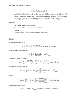


© Copyright 2026