
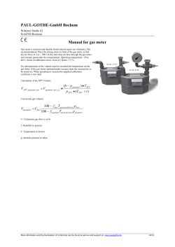
Gilflo ILVA Flowmeter with Mass Flow Transmitter and Compact Stem Description
Gilflo ILVA Flowmeter
with Mass Flow Transmitter and Compact Stem
DN250 and DN300 (10” and 12”)
Description
2
The compact Gilflo ILVA flowmeter is a three element flowmeter. It
operates on the spring loaded variable area principle and produces a
differential pressure related to the flowrate. The ILVA pipeline element
is connected to the Scanner 2000 steam mass flow transmitter via a
compact stem and isolation manifold.
The compact ILVA flowmeter is supplied as separate elements
(calibrated) as standard, although the pipeline element (ILVA) and
Scanner 2000 are a matched pair.
The flowmeter can also be supplied as a fully assembled and
calibrated system on request.
3
Sizes and pipe connections
DN250 and DN300 (10” and 12”).
Suitable for fitting between the following flanges:
EN 1092 PN16, PN25 and PN40.
ASME (ANSI) B 16.5 Class 150, 300 and 600.
JIS 20 / KS 20.
The Gilflo ILVA flowmeter should be installed in pipework
manufactured to BS 1600 or ASME (ANSI) B 36.10 Schedule 40.
For different pipe standards / schedules, downstream spool pieces
with an equivalent internal diameter to BS 1600 or ASME (ANSI)
B 36.10 Schedule 40 should be used. If this is not possible,
please contact Spirax Sarco Limited.
1
5
11 and 14
Configuration
The Gilflo ILVA and Scanner 2000 are uniquely configured at the
factory as a matched pair for a specific application. For correct
operation they must be installed together. A label on the packaging
gives the serial number of the matched products.
The product can be configured using an RS485 equipped PC with
the supplied configuration software.
Materials
4
12 and 14
9
No.Part
Material
1Body
Cast stainless steel S.316 (CF8M / 1.4408)
2Internals
431 S29 / S303 / S304 / S316
3Spring
Inconel X750
4 Compact stem Cast stainless steel S.316 (CF8M / 1.4408)
Stem to Gilflo
5
Corruseal - Stainless Steel Grade 321
ILVA gasket
Stem to 6
Grafoil
manifold gasket
Cast aluminium 7 Enclosure
(painted with epoxy and polyurethane)
8 Body Stainless steel
AISI 316
9 3-way manifold* Stainless steel
AISI 316
10 Fluid fill
Silicone oil (inside DP Cell (item 8))
stem toStainless steel
11 Compact
ILVA screws
Compact stem to
12
Manifold screws Stainless steel
Manifold to
13
Grafoil
MVT gasket
14 Spring washer
8
7
Stainless steel
*Note: 5-way manifold available as an option.
20
13
Local regulation may restrict the use of this product below the conditions quoted. Limiting conditions refer to standard connections only.
In the interests of development and improvement of the product, we reserve the right to change the specification.
TI-P337-59-US 12.12
Gilflo ILVA Flowmeter
with Mass Flow Transmitter and Compact Stem
DN250 and DN300 (10” and 12”)
Temperature °F
Gilflo
ILVA with
mass flow
transmitter
and
compact
stem
Temperature °C
Pressure psi g
Steam
saturation
curve
The product must not be used in this region.
The product should not be used in this region
or beyond its operating range as damage to
the internals may occur.
Pressure bar g
Body design conditions ASME (ANSI) 600
PMA Maximum allowable pressure 99 bar g @ 38°C (1 435 psi g @ 100°F)
TMA Maximum allowable temperature 400°C @ 59 bar g (752°F @ 855 psi g)
-29°C (-20°F)
Minimum allowable temperature
Compact stem versions
0°C
(32°F)
Maximum operating 99 bar g @ 38°C (1 435 psi g @ 100°F)
PMO
pressure Compact stem versions 32 bar g @ 239°C (464 psi g @ 462°F)
Minimum operating pressure 0.6 bar g (8.7 psi g)
Maximum operating 400°C @ 59 bar g (752°F @ 855 psi g)
TMO temperature
Compact stem versions 239°C @ 32 bar g (462°F @ 464 psi g)
-29°C (-20°F)
Minimum operating temperature
Compact stem versions
0°C
(32°F)
Note: For lower operating temperatures consult Spirax Sarco.
Maximum viscosity 30 centipoise
30 centipoise
∆PMX Maximum differential pressure 498 m bar
(7.2 psi g)
Designed for a maximum cold hydraulic test pressure of: 142 bar g (2 059 psi g)
Performance
The Gilflo ILVA is used in conjunction with linearising electronics such as the M800 flow computer or M750 display unit.
Alternatively the output signal linearisation can be performed on an EMS / BEMS or equivalent.
Accuracy when used with Scanner 2000 or M750:
±1% of measured value from 5% to 100% of maximum rated flow.
±0.1% FSD from 1% to 5% of maximum rated flow.
Repeatability better than 0.25%
Turndown: up to 100:1
Caution: The Scanner 2000 mass flow transmitters can be configured at the factory to work with a single, specific Gilflo ILVA flowmeter. For
correct operation the configured transmitter must always be installed with its allocated flowmeter. Labels on the packaging give the serial numbers of the matched products.
Pressure drop
The maximum pressure drop across the Gilflo ILVA pipeline unit is 498 m bar (200 ins water gauge) at maximum rated flow.
Flow capacity
To determine the capacity of the Gilflo ILVA for different fluids, it is necessary to calculate the equivalent water flowrate QE (in l/min)
as described in Step 1, under the section ‘sizing the Gilflo ILVA’ then selecting the appropriate size of flowmeter from the Table under Step 2
overleaf.
Mass Flow Transmitter (Scanner 2000) Technical Data
Range
Outputs
Power supply
Pressure limits
Minimum 2" H 2 0 (4.98 mbar)
Maximum 200" H 2 0 (498 mbar)
4 - 20 mA (expansion board required)
RS485 Modbus RTU slave (baud rate 300 to 38.4 K)
Solid state relay, configurable as pulse or alarm
6 V to 30 Vdc at 31 mA
155 bar
-40°C to 70°C (-40°F to 158°F)
Temperature limits
LCD contrast is reduced below -30°C (-22°F)
±0.05% for Spans >10% of the URL
Accuracy
±0.005 (URL/SPAN) for Spans <10% of the sensor
Enclosure rating
IEC IP68
Scanner certification
ATEX or CSA approved (see Scanner literature for details)
TI-P337-59-US
12.12
Spirax Sarco Inc. • 2150 Miller Drive • Longmont, CO 80501 • Telephone: (303) 682-7060 • Fax: (303) 682-7069
21
Gilflo ILVA Flowmeter
with Mass Flow Transmitter and Compact Stem
DN250 and DN300 (10” and 12”)
Dimensions / weights
(approximate) in inches and pounds
Size
A
B C
D
E
F
G
H
Weight
10" 4.1 8.017.513.01.4 1.425.28.3 112
12" 4.7 9.820.915.21.7 1.427.48.3 165
C
B
A
F
E
D
G
H
Spirax Sarco Inc. • 2150 Miller Drive • Longmont, CO 80501 • Telephone: (303) 682-7060 • Fax: (303) 682-7069
22
TI-P337-59-US
12.12
Gilflo ILVA Flowmeter with Mass Flow Transmitter and
Compact Stem DN250 and DN300 (10” and 12”)
Sizing the Gilflo ILVA flowmeter
In order to determine the flow capacity of a Gilflo ILVA pipeline unit, it is necessary to calculate the equivalent water flowrate (QE) based on the
anticipated actual flow (see Step 1).
The Table below is used to select the appropriate unit (steam only).
Step 1.
Determine equivalent water flowrate (QE) in l/min:Mass flow units
Liquids
QE =
qm
Volumetric units
QE = QL SG
SG
Gases
1 000
and steam
Q E = qM
actual flow DF
conditions
QE = QF
Step 2.
Using the value of QE as determined in Step 1, select
the correct size of the Gilflo ILVA flowmeter using the Table
below. In practice, it will often be the line size that determines the
choice of the flowmeter.
Flowmeter type
DN250
DN300
DF
1 000
DS
P
T
Gases
DS
PF PF
x Sx F
QE = QS
= QS
x
x
standard QE 1
000
P
T
1 000 PS TS
F
S
conditions
Where:
QE = Equivalent water flowrate (litres/min)
qm = Mass flowrate (kg/min)
QL = Maximum liquid flowrate (litres/min)
QS = Maximum gas flowrate at standard conditions (litres/min)
QF = Maximum gas flowrate at actual flow conditions (litres/min)
SG = Specific gravity
DS = Density of gas at standard conditions (kg/m³)
DF = Density of gas at actual flow conditions (kg/m³)
PS = Standard pressure: 1.013 bar a, 1.033 kg/cm2 a, 14.70 psi a
PF = Actual flow pressure in same absolute units as PS
TS = Standard temperature (K) = °C + 273
TF = Actual flow temperature (K) = °C + 273
Max. QE
litres /min
7 750
10 975
Maximum pressure drop
Wg
200
200
Example: Determine which Gilflo pipeline unit is required to
measure the flow of compressed air when:
1: Estimated maximum rate of flow = 28000 s m³ /h at 7 bar g and 20°C.
Note: Standard conditions = 1.013 bar a, 0°C giving a standard
density of 1.29 kg / m³
2: Calculate QE from:
QE = QS
DS
P
T
x S x DF S
P
P
1Q
000
PSF TS x F x F
E = Q
1 000 PS TS
QE =(28 000 x 16.667) x
1.29
1 000
x
1.013
8.013
x
293
273
QE = 6 174 litres /min
So a DN250 ILVA is recommended.
Note: 1 m³ / h = 16.667 litres /min
Sizing - Gilflo ILVA flowmeter minimum and maximum saturated steam flowrates in lb / hr
Notes:
1. These capacities are based on a differential pressure across the flowmeter of 498 m bar H20 (200 Inches).
2. Minimum flow is 1% of maximum (100:1 turndown).
3. The table below is a guide only.
Size
10”
12”
QE
Max
Min
Max
Min
17,086
171
24,196
242
15
35,241
352
49,906
499
45
48,910
489
69,263
693
75
59,337
593
84,029
840
100
68,121
681
96,470
965
Steam pressure psig
145
175
220
79,461
86,199
95,443
793
862
954
112,528 122,068 135,159
1,123
1,221
1,351
290
109,219
1,092
154,670
1,547
360
121,596
1,216
172,196
1,722
435
132,994
1,330
188,336
1,883
580
153,790
1,538
217,768
2,178
Safety information, installation and maintenance
For full details see the Installation and Maintenance Instructions supplied with the product.
Installation note:
The following main points are given here for guidance:
1.The Gilflo ILVA should be mounted with a minimum of 6 straight pipe diameters upstream and 3 downstream. No valves, fittings or cross
sectional changes are permitted within these pipe lengths. Where an increase in nominal pipe diameter is required upstream of the flowmeter,
the length of straight pipe should be increased to 12 diameters. Similarly, where a Gilflo ILVA is installed downstream of two 90 degree bends
in two planes, a pressure reducing valve or a partially open valve, 12 upstream pipe diameters should be allowed.
2.It is important that the internal upstream and downstream diameters of pipe are smooth. Ideally seamless pipes should be used. It is recommended that slip-on flanges be used to avoid any intrusive weld beads on the internal diameter of the pipe.
3.Care should be taken to install the Gilflo ILVA concentrically in the line. If this is not done, flow measurement errors may occur.
4.The Gilflo ILVA should be mounted horizontally.
5.For steam applications, good basic steam engineering practices should be followed:
- Correct line drainage through adequate trapping.
- Good alignment and support of associated pipework.
- Line size changes achieved by the use of eccentric reducers.
How to order example
1 off Spirax Sarco DN250 Gilflo ILVA flowmeter with compact stem, three way isolation manifold and saturated steam mass flow transmitter
with ANALOG OUTPUT (4 - 20 mA) ATEX II 2 GD Ex d IIC T6 approved for installation between EN 1092 PN40 flanges. The body material is to
be 316 stainless steel. The flow medium will be saturated steam at 10 bar g and the maximum flow will be 36 000 kg / h. TI-P337-59-US 12.12
Spirax Sarco Inc. • 2150 Miller Drive • Longmont, CO 80501 • Telephone: (303) 682-7060 • Fax: (303) 682-7069
23
Gilflo ILVA Flowmeter
with Mass Flow Transmitter and Compact Stem
DN250 and DN300 (10” and 12”)
Spare parts
The spare parts available are detailed below. No other parts are supplied as spares.
5
Available spares
Gasket set
5, 6, 13
Compact stem screws and spring washers11, 12, 14
14
11
How to order spares
Always order spares by using the description given in the
column headed 'Available spares' and state the size and
type of equipment.
12
Example: 1 - Gasket set for a Spirax Sarco DN250 Gilflo ILVA
flowmeter with mass flow transmitter and compact stem
suitable for fitting between EN 1092 PN16 connections.
14
6
13
TI-P337-59-US
Spirax Sarco Inc. • 2150 Miller Drive • Longmont, CO 80501 • Telephone: (303) 682-7060 • Fax: (303) 682-7069
24
12.12


© Copyright 2026