
Balanced Pressure Thermostatic Steam Traps RTA-125, RTH-125, RTV-125
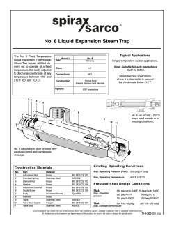
Balanced Pressure Thermostatic Steam Traps
RTA-125, RTH-125, RTV-125
The balanced pressure steam trap
RTA-125RTH-125RTV-125
Model Í
AngleStraightway
Vertical
contains a welded stainless steel element which is self-adjusting
PMO 125 psig 125 psig
125 psig
over the entire operating pressure range and approximately 23˚F (13˚C) below saturated steam temSizes
1/2", 3/4" & 1" 1/2" & 3/4" 1/2" & 3/4"
perature.
NPT — male union inlet
Connections
Traps in this series are replace- NPT — female outlet
ments for:
ConstructionBrass body with stainless steel internals
TA-125, TH-125, T-25, TB-25,
TS-25, T-65, T-125; 1"H, N-100
E
xtended male inlet spud (1/2", 3/4" RTA-125 only)
Option
angle; H, S-65, N-100 straight
N
ear to steam fill 11°F (6°C) All
way and vertical, TV-125.
7
5
1
4
6
Vapor or vacuum two-pipe
heating systems, radiators,
convectors, fintube, hospital
blanket warmers, sterilizers
and stills, laundry and kitchen
equipment, and small process
equipment.
Capacity
2
Differential Pressure bar
•1
•2
•3
•5
1
2
2000
4000
9
1500
3000
8
2000
1000
R
TE
A
DW
700
L
CO
1500
4
3
2
7
5
1
6
Condensate lb/h
8
8
2500
500
1000
9
5
6000
5000
3
1/2", 3/4" RTH
3
HOT
700
TE
SA
DEN
CON
400
300
500
200
400
300
100
200
Condensate kg/h
1/2", 3/4", 1" RTA
Typical Applications
150
50
100
1
2
3
4
5
7
10
Differential Pressure psi
Orifice Size = .196"
1/2", 3/4", RTV
8
9
2
1
3
5
4
6
9
8
15 20
30
50
100 125
Water Capacity
Hot Condensate
Construction Materials
No. Part Material
1
Body
Forged Red Brass ASTM B124 Alloy C3770
TV-125 ASTM B62
2
Cap Forged Red Brass ASTM B124 Alloy C3770
3
Seat
Stainless Steel
4
Thermostat Stainless Steel BP99
5
Spring
Stainless Steel
6
Seat Gasket
Brass
7
O-Ring
EPDM
8
Union Nipple
Brass
ASTM B16
9
Union Nut
Brass
ASTM B16
Local regulation may restrict the use of this product below the conditions quoted. Limiting conditions refer to standard connections only.
In the interests of development and improvement of the product, we reserve the right to change the specification.
2:190
70
TI-2-0102-US
4.12
Balanced Pressure Thermostatic Steam Traps
RTA-125, RTH-125, RTV-125
Dimensions (nominal) in inches and millimeters
Spare Parts
A
B
RTV
RTA, RTH
C
Size Type
Body Pattern
1/2" RTA-125Angle
RTH-125 Straightway
RTV-125
Vertical
A B C DE FG Weight
2.8*1.21.01.9– – – 1 lb
71 302548– – – 0.5 kg
3.2 –
1.2 1.9 1.4 0.7 1.1 1.4 lb
83
–
32 48 35 18 16 0.6 kg
5.1
––2.0
– ––1.6 lb
130– –51
–
–
–
7 kg
3/4" RTA-125 Angle
RTH-125 Straightway
RTV-125
Vertical
3.0* 1.20 1.0 1.9 –
–
–
1.3 lb
78 322548– – – 0.6 kg
3.2 –
1.20 1.9 1.4 0.8 1.1 1.8 lb
83
–
32 48 35 20 29 0.6 kg
5.6
––2.0
– ––2 lb
141– –51
–
–
–
9 kg
1"
RTA-125 Angle
D
3.5 2.0 1.2 1.9 –
–
–
2.8 lb
89 514448– – – 1.2 kg
* with optional extended inlet spud, "A" dimension is 3.2".
D
D
E
C
C
F
B
B
G
A*
B, C, D, E, F, G
Cap Assembly (RTA, RTH)
Repair Kit (RTV)
A
1/2", 3/4" RTA-125
A, B
1" RTA-125
D
D
C, D, E, F,G
C
Limiting Operating Conditions
Max. Operating Pressure (PMO) 125 psig (8.6 barg)
Max. Operating Temperature Saturated Steam Temperature
Minimum Operating Pressure 25" Hg Vacuum
Pressure Shell Design Conditions
PMA
125 psig/up to 353˚F
8.6 barg/up to 179˚C
353˚F/0-125 psig
179˚C/0-8.6 barg
Max. allowable pressure
TMA
Max. allowable temperature
Sample Specification RTA, RTH
Steam traps shall be balanced pressure thermostatic type, selfadjusting to all pressures within their operating range. Bodies
to be of forged red brass with male union inlet connection.
Thermostatic element shall be of precision welded stainless steel
construction, incorporating a hardened stainless steel valve head.
Valve seats shall be stainless steel, and all internals, shall be
replaceable without disturbing the piping connections.
A
G
F
A
E
1/2", 3/4" RTH-125
1/2", 3/4" RTV-125
Installation
A pipeline strainer should be installed ahead of any steam trap to protect the head and seat from dirt and scale. Full port isolating valves
should be placed to permit servicing. Trap should be installed below the
drainage point of the equipment with a collecting leg before the trap. For
best operation, the element should be in a horizontal position as shown.
For a freeze-resistant installation, inlet piping must be pitched toward
the trap for gravity flow and the trap outlet must be free of any piping.
Maintenance
This product can be maintained without disturbing the piping connections. Complete isolation of the trap from both supply and return line is
required before any servicing is performed.
The trap should be disassembled periodically for inspection and cleaning
of the valve head and seat.
Worn or damaged parts should be replaced using a complete Repair Kit.
Complete installation and maintenance instructions are
given in IM-2-004-US, which accompanies the product.
Spirax Sarco, Inc., 1150 Northpoint Blvd, Blythewood, SC 29016
TI-2-0102-US
Telephone: (803) 714-2000 FAX (803) 714-2222
© Spirax Sarco, Inc. 2012
Repair Kit (RTA, RTH)
4.12


© Copyright 2026