
MCP37X1X-200 12-Bit 200 Msps ADC VTLA Evaluation Kit User’s Guide
MCP37X1X-200
12-Bit 200 Msps ADC VTLA
Evaluation Kit
User’s Guide
2014 Microchip Technology Inc.
DS50002326A
Note the following details of the code protection feature on Microchip devices:
•
Microchip products meet the specification contained in their particular Microchip Data Sheet.
•
Microchip believes that its family of products is one of the most secure families of its kind on the market today, when used in the
intended manner and under normal conditions.
•
There are dishonest and possibly illegal methods used to breach the code protection feature. All of these methods, to our
knowledge, require using the Microchip products in a manner outside the operating specifications contained in Microchip’s Data
Sheets. Most likely, the person doing so is engaged in theft of intellectual property.
•
Microchip is willing to work with the customer who is concerned about the integrity of their code.
•
Neither Microchip nor any other semiconductor manufacturer can guarantee the security of their code. Code protection does not
mean that we are guaranteeing the product as “unbreakable.”
Code protection is constantly evolving. We at Microchip are committed to continuously improving the code protection features of our
products. Attempts to break Microchip’s code protection feature may be a violation of the Digital Millennium Copyright Act. If such acts
allow unauthorized access to your software or other copyrighted work, you may have a right to sue for relief under that Act.
Information contained in this publication regarding device
applications and the like is provided only for your convenience
and may be superseded by updates. It is your responsibility to
ensure that your application meets with your specifications.
MICROCHIP MAKES NO REPRESENTATIONS OR
WARRANTIES OF ANY KIND WHETHER EXPRESS OR
IMPLIED, WRITTEN OR ORAL, STATUTORY OR
OTHERWISE, RELATED TO THE INFORMATION,
INCLUDING BUT NOT LIMITED TO ITS CONDITION,
QUALITY, PERFORMANCE, MERCHANTABILITY OR
FITNESS FOR PURPOSE. Microchip disclaims all liability
arising from this information and its use. Use of Microchip
devices in life support and/or safety applications is entirely at
the buyer’s risk, and the buyer agrees to defend, indemnify and
hold harmless Microchip from any and all damages, claims,
suits, or expenses resulting from such use. No licenses are
conveyed, implicitly or otherwise, under any Microchip
intellectual property rights.
Trademarks
The Microchip name and logo, the Microchip logo, dsPIC,
FlashFlex, flexPWR, JukeBlox, KEELOQ, KEELOQ logo, Kleer,
LANCheck, MediaLB, MOST, MOST logo, MPLAB,
OptoLyzer, PIC, PICSTART, PIC32 logo, RightTouch, SpyNIC,
SST, SST Logo, SuperFlash and UNI/O are registered
trademarks of Microchip Technology Incorporated in the
U.S.A. and other countries.
The Embedded Control Solutions Company and mTouch are
registered trademarks of Microchip Technology Incorporated
in the U.S.A.
Analog-for-the-Digital Age, BodyCom, chipKIT, chipKIT logo,
CodeGuard, dsPICDEM, dsPICDEM.net, ECAN, In-Circuit
Serial Programming, ICSP, Inter-Chip Connectivity, KleerNet,
KleerNet logo, MiWi, MPASM, MPF, MPLAB Certified logo,
MPLIB, MPLINK, MultiTRAK, NetDetach, Omniscient Code
Generation, PICDEM, PICDEM.net, PICkit, PICtail,
RightTouch logo, REAL ICE, SQI, Serial Quad I/O, Total
Endurance, TSHARC, USBCheck, VariSense, ViewSpan,
WiperLock, Wireless DNA, and ZENA are trademarks of
Microchip Technology Incorporated in the U.S.A. and other
countries.
SQTP is a service mark of Microchip Technology Incorporated
in the U.S.A.
Silicon Storage Technology is a registered trademark of
Microchip Technology Inc. in other countries.
GestIC is a registered trademarks of Microchip Technology
Germany II GmbH & Co. KG, a subsidiary of Microchip
Technology Inc., in other countries.
All other trademarks mentioned herein are property of their
respective companies.
© 2014, Microchip Technology Incorporated, Printed in the
U.S.A., All Rights Reserved.
ISBN: 978-1-63276-788-2
QUALITY MANAGEMENT SYSTEM
CERTIFIED BY DNV
== ISO/TS 16949 ==
DS50002326A-page 2
Microchip received ISO/TS-16949:2009 certification for its worldwide
headquarters, design and wafer fabrication facilities in Chandler and
Tempe, Arizona; Gresham, Oregon and design centers in California
and India. The Company’s quality system processes and procedures
are for its PIC® MCUs and dsPIC® DSCs, KEELOQ® code hopping
devices, Serial EEPROMs, microperipherals, nonvolatile memory and
analog products. In addition, Microchip’s quality system for the design
and manufacture of development systems is ISO 9001:2000 certified.
2014 Microchip Technology Inc.
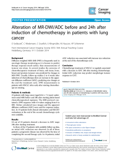
Object of Declaration: MCP37X1X-200 12-Bit 200 Msps ADC VTLA Evaluation Kit
2014 Microchip Technology Inc.
DS50002326A-page 3
MCP37X1X-200 12-BIT 200 MSPS ADC VTLA
EVALUATION KIT USER’S GUIDE
Table of Contents
Preface ........................................................................................................................... 5
Introduction............................................................................................................ 5
Document Layout .................................................................................................. 5
Conventions Used in this Guide ............................................................................ 6
Recommended Reading........................................................................................ 7
The Microchip Web Site ........................................................................................ 7
Customer Support ................................................................................................. 7
Document Revision History ................................................................................... 7
Chapter 1. Product Overview
1.1 Introduction ..................................................................................................... 9
1.2 What is the MCP37X1X-200 12-Bit 200 Msps ADC VTLA
Evaluation Board (ADM00619)? ............................................................... 9
1.3 What is the MCP37XXX High-Speed Pipeline ADC
Data Capture Card (ADM00506)? .......................................................... 11
1.4 What is the Pipeline ADC Utility Software? .................................................. 13
1.5 MCP37X1X-200 12-Bit 200 Msps ADC VTLA
Evaluation Kit Requirements .................................................................. 13
Chapter 2. Installation and Operation
2.1 MCP37X1X-200 12-Bit 200 Msps ADC VTLA Evaluation Kit Features ........ 15
2.2 Getting Started ............................................................................................. 15
2.2.1 Configuration Requirements ...................................................................... 15
2.2.2 Evaluation Kit Set-Up ................................................................................ 16
2.2.3 Power Input Connection ............................................................................ 16
2.2.4 Input/Output Optimization .......................................................................... 18
Appendix 1. Schematics and Layouts........................................................................ 19
Appendix 2. Bill of Materials (BOM) ........................................................................... 21
Worldwide Sales and Service .................................................................................... 22
DS50002326A-page 4
2014 Microchip Technology Inc.
MCP37X1X-200 12-BIT 200 MSPS ADC VTLA
EVALUATION KIT USER’S GUIDE
Preface
NOTICE TO CUSTOMERS
All documentation becomes dated, and this manual is no exception. Microchip tools and
documentation are constantly evolving to meet customer needs, so some actual dialogs
and/or tool descriptions may differ from those in this document. Please refer to our web site
(www.microchip.com) to obtain the latest documentation available.
Documents are identified with a “DS” number. This number is located on the bottom of each
page, in front of the page number. The numbering convention for the DS number is
“DSXXXXXXXXA”, where “XXXXXXXX” is the document number and “A” is the revision level
of the document.
For the most up-to-date information on development tools, see the MPLAB® IDE online help.
Select the Help menu, and then Topics to open a list of available online help files.
INTRODUCTION
This chapter contains general information that will be useful to know before using the
MCP37X1X-200 12-Bit 200 Msps ADC VTLA Evaluation Kit. Items discussed in this
chapter include:
•
•
•
•
•
•
Document Layout
Conventions Used in this Guide
Recommended Reading
The Microchip Web Site
Customer Support
Document Revision History
DOCUMENT LAYOUT
This document describes how to use the MCP37X1X-200 12-Bit 200 Msps ADC VTLA
Evaluation Kit to demonstrate the performance of the MCP37X1X-200 device family.
The manual layout is as follows:
• Chapter 1. “Product Overview” – Important information about the
MCP37X1X-200 12-Bit 200 Msps ADC VTLA Evaluation Kit.
• Chapter 2. “Installation and Operation” – Includes instructions on how to get
started with the MCP37X1X-200 12-Bit 200 Msps ADC VTLA Evaluation Kit.
• Appendix 1. “Schematics and Layouts” – Refer to the board’s web page for the
complete Schematics and Layouts.
• Appendix 2. “Bill of Materials (BOM)” – Refer to the board’s web page for the
complete Bill of Materials
2014 Microchip Technology Inc.
DS50002326A-page 5
MCP37X1X-200 12-Bit 200 Msps ADC VTLA Evaluation Kit User’s Guide
CONVENTIONS USED IN THIS GUIDE
This manual uses the following documentation conventions:
DOCUMENTATION CONVENTIONS
Description
Arial font:
Italic characters
Initial caps
Quotes
Underlined, italic text with
right angle bracket
Bold characters
N‘Rnnnn
Text in angle brackets < >
Courier New font:
Plain Courier New
Represents
Referenced books
Emphasized text
A window
A dialog
A menu selection
A field name in a window or
dialog
A menu path
MPLAB® IDE User’s Guide
...is the only compiler...
the Output window
the Settings dialog
select Enable Programmer
“Save project before build”
A dialog button
A tab
A number in verilog format,
where N is the total number of
digits, R is the radix and n is a
digit.
A key on the keyboard
Click OK
Click the Power tab
4‘b0010, 2‘hF1
Italic Courier New
Sample source code
Filenames
File paths
Keywords
Command-line options
Bit values
Constants
A variable argument
Square brackets [ ]
Optional arguments
Curly brackets and pipe
character: { | }
Ellipses...
Choice of mutually exclusive
arguments; an OR selection
Replaces repeated text
Represents code supplied by
user
DS50002326A-page 6
Examples
File>Save
Press <Enter>, <F1>
#define START
autoexec.bat
c:\mcc18\h
_asm, _endasm, static
-Opa+, -Opa0, 1
0xFF, ‘A’
file.o, where file can be
any valid filename
mcc18 [options] file
[options]
errorlevel {0|1}
var_name [,
var_name...]
void main (void)
{ ...
}
2014 Microchip Technology Inc.
Preface
RECOMMENDED READING
This user's guide describes how to use the MCP37X1X-200 12-Bit 200 Msps ADC
VTLA Evaluation Kit. Other useful documents are listed below. The following Microchip
document is available and recommended as a supplemental reference resource.
• MCP37211-200/MCP37D11-200 Data Sheet – “200 Msps, 12-Bit Low-Power
ADC with 8-Channel MUX” (DS20005355)
THE MICROCHIP WEB SITE
Microchip provides online support via our web site at www.microchip.com. This web
site is used as a means to make files and information easily available to customers.
Accessible by using your favorite Internet browser, the web site contains the following
information:
• Product Support – Data sheets and errata, application notes and sample
programs, design resources, user’s guides and hardware support documents,
latest software releases and archived software
• General Technical Support – Frequently Asked Questions (FAQs), technical
support requests, online discussion groups, Microchip consultant program
member listing
• Business of Microchip – Product selector and ordering guides, latest Microchip
press releases, listing of seminars and events, listings of Microchip sales offices,
distributors and factory representatives
CUSTOMER SUPPORT
Users of Microchip products can receive assistance through several channels:
•
•
•
•
Distributor or Representative
Local Sales Office
Field Application Engineer (FAE)
Technical Support
Customers should contact their distributor, representative or field application engineer
(FAE) for support. Local sales offices are also available to help customers. A listing of
sales offices and locations is included in the back of this document.
Technical support is available through the web site at:
http://www.microchip.com/support.
DOCUMENT REVISION HISTORY
Revision A (November 2014)
• Initial Release of this document.
2014 Microchip Technology Inc.
DS50002326A-page 7
MCP37X1X-200 12-Bit 200 Msps ADC VTLA Evaluation Kit User’s Guide
NOTES:
DS50002326A-page 8
2014 Microchip Technology Inc.
MCP37X1X-200 12-BIT 200 MSPS ADC VTLA
EVALUATION KIT USER’S GUIDE
Chapter 1. Product Overview
1.1
INTRODUCTION
This chapter provides an overview of the MCP37X1X-200 12-Bit 200 Msps ADC VTLA
Evaluation Kit and covers the following topics:
• What is the MCP37X1X-200 12-Bit 200 Msps ADC VTLA Evaluation Board
(ADM00619)?
• What is the MCP37XXX High-Speed Pipeline ADC Data Capture Card
(ADM00506)?
• What is the Pipeline ADC Utility Software?
• MCP37X1X-200 12-Bit 200 Msps ADC VTLA Evaluation Kit requirements
1.2
WHAT IS THE MCP37X1X-200 12-BIT 200 MSPS ADC VTLA EVALUATION
BOARD (ADM00619)?
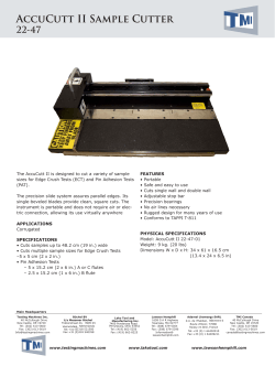
The MCP37X1X-200 12-Bit 200 Msps ADC VTLA Evaluation Board (ADM00619) is
intended to demonstrate the performance of the MCP37X1X-200 device family. This
evaluation board is used together with:
• MCP37XXX High-Speed Pipeline ADC Data Capture Card (ADM00506)
• Pipeline ADC Utility Software
Refer to Figure 1-1 for the system setup.
5V
5V
MCP37X1X-200
Evaluation Board
(Note 1)
MCP37XXX
Data Capture
Card Board
(Note 2)
Note 1:
2:
3:
FIGURE 1-1:
USB
PC GUI
(Pipeline ADC
Utility Software)
(Note 3)
The ADC part is available on this board.
This board collects ADC data from the evaluation board and passes it to the PC GUI.
This GUI allows the user to test the performance of the MCP37X1X-200 device.
Evaluation Kit System Setup.
This evaluation board supports the following Microchip high-speed ADC device
families:
• The MCP37X1X-200, which is Microchip Technology Inc.’s baseline 12-bit
200 Msps pipelined analog-to-digital converter (ADC) device family, featuring a
built-in high-order digital decimation filter, gain and offset adjustment per channel,
and fractional delay recovery.
• The MCP37D1X-200 device family, which features digital down-conversion and
CW beamforming capability, in addition to the features offered by the baseline
device family.
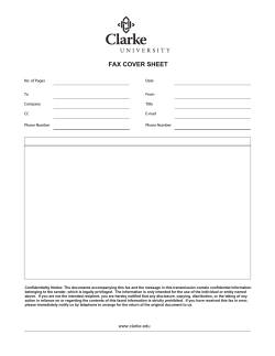
The MCP37X1X-200 12-Bit 200 Msps ADC VTLA Evaluation Board (ADM00619)
comes with the MCP37D11-200 device on board. All conditions and features can be
evaluated using this device. Refer to Figure 1-2 for close-up photos of the evaluation
board.
2014 Microchip Technology Inc.
DS50002326A-page 9
MCP37X1X-200 12-Bit 200 Msps ADC VTLA Evaluation Kit User’s Guide
(a) Top View
MCP37D11-200
(b) Bottom View
FIGURE 1-2:
DS50002326A-page 10
MCP37X1X-200 12-Bit 200 Msps ADC VTLA Evaluation Board (ADM00619).
2014 Microchip Technology Inc.
Product Overview
1.3
WHAT IS THE MCP37XXX HIGH-SPEED PIPELINE ADC DATA CAPTURE
CARD (ADM00506)?
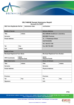
The MCP37XXX High-Speed Pipeline ADC Data Capture Card (ADM00506) is an
FPGA-based memory buffer for the digital data received from the Analog-to-Digital
Converter (ADC) evaluation board. Figure 1-1 shows the connection of the data
capture card directly between the evaluation board and the PC GUI.
The data capture card connects to the PC through a USB cable, providing the user with
two functionalities:
• The ability to send user commands directly to the device from the PC GUI
• The ability to collect data from the evaluation board and send it to the PC GUI.
Refer to Figure 1-3 for close-up photos of the data capture card.
2014 Microchip Technology Inc.
DS50002326A-page 11
MCP37X1X-200 12-Bit 200 Msps ADC VTLA Evaluation Kit User’s Guide
(a) Top View
(b) Bottom View
FIGURE 1-3:
DS50002326A-page 12
MCP37XXX High-Speed Pipeline ADC Data Capture Card (ADM00506).
2014 Microchip Technology Inc.
Product Overview
1.4
WHAT IS THE PIPELINE ADC UTILITY SOFTWARE?
The Pipeline ADC Utility software is the graphical user interface (GUI) used to
communicate with and to configure the operating parameters of the device. The
software communicates with the part through the data capture card via a USB cable,
allowing the user to program the internal ADC registers. When the user interacts with
the software (for example, by updating the registers), the user’s commands are passed
to the MCP37X1X-200 device via the data capture card. Once the commands are
executed by the evaluation board, the software receives the requested data from the
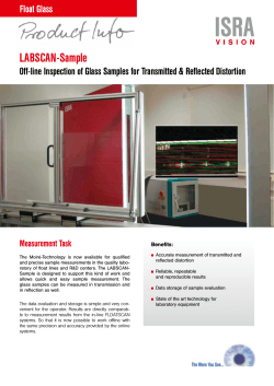
data capture card. The software will then analyze the data, perform an FFT or other
analysis, and display the results. Please refer to Figure 1-1 for a diagram of the system
setup. Figure 1-4 shows a screen shot of the graphical interface.
FIGURE 1-4:
Pipeline ADC Utility Software Displaying a Typical FFT Waveform.
The Pipeline ADC Utility software is available for download on Microchip’s web site. For
instructions on using the GUI, refer to the software’s supporting documentation
included with the installation file, as well as within the application Help menu.
1.5
MCP37X1X-200 12-BIT 200 MSPS ADC VTLA EVALUATION KIT
REQUIREMENTS
The evaluation kit requires the following:
• MCP37X1X-200 12-Bit 200 Msps ADC VTLA Evaluation Board (ADM00619)
• MCP37XXX High-Speed Pipeline ADC Data Capture Card (ADM00506)
- Sold separately
• Two 5V Wall-Mountable Switching Power Supplies
- Included with the evaluation board and data capture card
2014 Microchip Technology Inc.
DS50002326A-page 13
MCP37X1X-200 12-Bit 200 Msps ADC VTLA Evaluation Kit User’s Guide
• USB-A to USB Mini-B Cable
- Included with the data capture card
• Pipeline ADC Utility Software
- Available on the Microchip web site
• Important Information Sheet
DS50002326A-page 14
2014 Microchip Technology Inc.
MCP37X1X-200 12-BIT 200 MSPS ADC VTLA
EVALUATION KIT USER’S GUIDE
Chapter 2. Installation and Operation
2.1
MCP37X1X-200 12-BIT 200 MSPS ADC VTLA EVALUATION KIT FEATURES
The MCP37X1X-200 12-Bit 200 Msps ADC VTLA Evaluation Kit is a fully assembled,
programmed and tested solution (with the exception of a clock source) to evaluate and
demonstrate the MCP37X1X-200 operating performance.
The evaluation kit has the following features:
• Programmable Full-Scale Analog Input Range
• Dynamic Performance Monitoring
• Evaluation of Performance Metrics, such as: SNR, SFDR, INL, DNL, etc.
• User-Programmable Registers
• Power Consumption Evaluation
• Digital Post-Processing Options: Decimation Filter, Digital Down-Conversion, CW
Beamforming, Noise-Shaping Requantizer, etc.
The evaluation kit features a sample rate of up to 200 Msps. Since the device can support up to 8 input channels, the effective sample rate per channel is a function of the
number of channels enabled. Refer to Table 2-1 for a detailed list of the input sample
rate per channel.
For information about the device features, please refer to the MCP37211-200/MCP37D11-200
Data Sheet.
TABLE 2-1:
2.2
INPUT SAMPLE RATE VS. NUMBER OF CHANNELS SELECTED
No. of Channels Selected
Sample Rate per Channel
(in Msps)
1
200
2
100
3
66.67
4
50
5
40
6
33.33
7
28.57
8
25
GETTING STARTED
2.2.1
Configuration Requirements
To power-up and run the evaluation kit, the following are required:
•
•
•
•
•
Pipeline ADC Utility Software
MCP37X1X-200 12-Bit 200 Msps ADC VTLA Evaluation Board (ADM00619)
MCP37XXX High-Speed Pipeline ADC Data Capture Card (ADM00506)
Two 5V Wall-Mountable Switching Power Supplies
A USB-A to USB Mini-B Cable
2014 Microchip Technology Inc.
DS50002326A-page 15
MCP37X1X-200 12-Bit 200 Msps ADC VTLA Evaluation Kit User’s Guide
2.2.2
1.
2.
3.
4.
5.
Evaluation Kit Set-Up
Connect the evaluation board and data capture card as shown in Figure 2-1.
Power-up both boards using the supplied 5V power supplies.
Connect the data capture card to a computer using the provided USB cable.
Press the reset button on both boards simultaneously.
Run the Pipeline ADC Utility Software.
For help with troubleshooting the boards and operating the GUI, please refer to the
software’s supporting documentation.
WARNING
Avoid connecting a power supply with a voltage greater than 5V. Doing so can damage
the voltage regulators, requiring them to be replaced.
2.2.3
Power Input Connection
This evaluation kit comes with two Mean Well wall-mountable switching power supplies
(GS06U-1P1J), one for each of the boards. These power supplies are able to provide
a 5V, 1A maximum output. They can be connected to an AC wall outlet rated between
90V AC and 264V AC, at a frequency of 47 Hz to 63 Hz. The other end of the power
supply is a 2.1 mm barrel plug that connects to both the evaluation board and the data
capture card (see Figure 2-1). If the user chooses to connect a different external power
supply, a minimum output of 750 mA is required.
The power domains on the evaluation board may be merged, if needed. Specifically,
the 1.2VA and 1.2VD power domains may be merged by populating a ferrite bead on
FB10. Similarly, the 1.8VA and 1.8VD power domains may be merged by populating a
ferrite bead on FB11. In both cases, the digital regulators should be disabled using the
appropriate switches.
The evaluation board’s power supplies can also be supplied by external voltages
directly to the power domains. This can be done by disabling the desired regulator
using the dip switch SW2 - Regulator Enable on the silkscreen. Then, a DC voltage can
be driven directly into the appropriate pin of header J16. Note that the even pins of the
J16 header are GND.
WARNING
Avoid applying an input signal while the board is powered off. This may damage the
input baluns! If a high second harmonic is seen, it is likely that these baluns need to be
replaced.
DS50002326A-page 16
2014 Microchip Technology Inc.
2014 Microchip Technology Inc.
Ferrite Locations
FB10 and FB11
Power
Header
External
Clock
Input
Unpopulated
Crystal Oscillator
Trace (Y1/Y2)
Xilinx
FPGA
Power
Supply
Input (5V)
Regulator
Switches
Data Capture
Card Reset
Switch
USB
Input
Analog
Inputs
DS50002326A-page 17
ADC Device
Under Test
(bottom side of the board)
Eval Board
Reset Switch
MCP37X1X-200, 12-Bit 200 Msps ADC VTLA
Evaluation Board (ADM00619)
FIGURE 2-1:
Board
Connectors
MCP37XXX High-Speed Pipeline ADC
Data Capture Card (ADM00506)
Evaluation Kit - The evaluation board connected to the data capture card.
Installation and Operation
Power
Supply
Input (5V)
MCP37X1X-200 12-Bit 200 Msps ADC VTLA Evaluation Kit User’s Guide
2.2.4
Input/Output Optimization
2.2.4.1
OPTIMIZING THE CLOCK CONNECTION
The evaluation board does not come with a clock source for the device. The user must
provide a clock source in order to run the evaluation board. The user has two options:
• A clean and low-jitter clock signal can be connected to the external clock SMA
input (see Figure 2-1). For the signal generation, Rohde & Schwarz® SMA or
Agilent Technologies HP8644B signal generators can be used. To ensure that a
clean and low-jitter clock signal is provided, the user should interpose a
band-pass filter to reduce the phase noise coming from the signal source.
A TTE® Inc. KC4T-200M-10P-50-3A filter can be used with a 200 MHz clock
signal.
• Alternatively, an unpopulated trace is available on the board, where the user can
place a crystal oscillator. For a single-ended clock, refer to the instructions in
Example 1. For a differential clock, refer to the instructions in Example 2. The
MCP37X1X-200 device is able to provide both LVDS and CMOS outputs. However, this evaluation kit is designed for LVDS outputs only. The user can modify
various other output data properties using the GUI, with the exception of the
LVDS/CMOS output mode. The user may also choose to place another type of
clock as well. Note that the component values given below are for example only
and may vary depending on the exact clock source used.
Example 1
A clock oscillator with a single ended output may be populated on Y1. The use of the
Crystek CCHD-950 series is recommended, such as CCHD-950-50-100.000 for a
100 MHz clock. In this case, proceed to the following modifications:
1. Remove R36
2. Populate R89 with a 50 resistor
3. Populate C106 with a 22 pF capacitor.
Example 2
A clock oscillator with a differential LVPECL output may be populated on Y2. The use
of the Crystek CCPD-034 series is recommended, such as the CCPD-034-50-200.000
for a 200 MHz clock. In this case, proceed to the following modifications:
1. Remove R36 and R136
2. Populate R89 and R90 with a 210 resistor
3. Populate C105 and C106 with a 22 pF capacitor.
2.2.4.2
OPTIMIZING THE ANALOG INPUT CONNECTION
The best way to evaluate the MCP37X1X-200 device is to use a clean analog input
signal with as little noise as possible. The signal can be provided using a signal
generator, such as Rohde & Schwarz SMA or Agilent Technologies HP8644B, and can
be used along with a bandpass filter. The filter will help with filtering the harmonic tones
of the fundamental, as well as with reducing the phase noise of the source. Two such
filters that can be used are:
• TTE Inc. KC4T-70M-15P-50-69A for 70 MHz input
• TTE inc. KC4T-20M-15P-50-69A for 20 MHz input.
2.2.4.3
OUTPUT DATA CONFIGURATION
The MCP37X1X-200 device is able to provide both LVDS and CMOS outputs.
However, this evaluation kit is designed for LVDS outputs only. The user can modify
various other output data properties using the GUI, with the exception of the
LVDS/CMOS output mode.
DS50002326A-page 18
2014 Microchip Technology Inc.
MCP37X1X-200 12-BIT 200 MSPS ADC VTLA
EVALUATION KIT USER’S GUIDE
Appendix 1. Schematics and Layouts
NOTICE TO CUSTOMERS
Refer to the board’s web page for the complete Schematics and Layouts.
2014 Microchip Technology Inc.
DS50002326A-page 19
MCP37X1X-200 12-Bit 200 Msps ADC VTLA Evaluation Kit User’s Guide
NOTES:
DS50002326A-page 20
2014 Microchip Technology Inc.
MCP37X1X-200 12-BIT 200 MSPS ADC VTLA
EVALUATION KIT USER’S GUIDE
Appendix 2. Bill of Materials (BOM)
NOTICE TO CUSTOMERS
Refer to the board’s web page for the complete Bill of Materials.
2014 Microchip Technology Inc.
DS50002326A-page 21
Worldwide Sales and Service
AMERICAS
ASIA/PACIFIC
ASIA/PACIFIC
EUROPE
Corporate Office
2355 West Chandler Blvd.
Chandler, AZ 85224-6199
Tel: 480-792-7200
Fax: 480-792-7277
Technical Support:
http://www.microchip.com/
support
Web Address:
www.microchip.com
Asia Pacific Office
Suites 3707-14, 37th Floor
Tower 6, The Gateway
Harbour City, Kowloon
Hong Kong
Tel: 852-2943-5100
Fax: 852-2401-3431
India - Bangalore
Tel: 91-80-3090-4444
Fax: 91-80-3090-4123
Austria - Wels
Tel: 43-7242-2244-39
Fax: 43-7242-2244-393
Denmark - Copenhagen
Tel: 45-4450-2828
Fax: 45-4485-2829
Australia - Sydney
Tel: 61-2-9868-6733
Fax: 61-2-9868-6755
Atlanta
Duluth, GA
Tel: 678-957-9614
Fax: 678-957-1455
China - Beijing
Tel: 86-10-8569-7000
Fax: 86-10-8528-2104
Austin, TX
Tel: 512-257-3370
China - Chengdu
Tel: 86-28-8665-5511
Fax: 86-28-8665-7889
Boston
Westborough, MA
Tel: 774-760-0087
Fax: 774-760-0088
Chicago
Itasca, IL
Tel: 630-285-0071
Fax: 630-285-0075
Cleveland
Independence, OH
Tel: 216-447-0464
Fax: 216-447-0643
Dallas
Addison, TX
Tel: 972-818-7423
Fax: 972-818-2924
Detroit
Novi, MI
Tel: 248-848-4000
Houston, TX
Tel: 281-894-5983
Indianapolis
Noblesville, IN
Tel: 317-773-8323
Fax: 317-773-5453
Los Angeles
Mission Viejo, CA
Tel: 949-462-9523
Fax: 949-462-9608
New York, NY
Tel: 631-435-6000
San Jose, CA
Tel: 408-735-9110
Canada - Toronto
Tel: 905-673-0699
Fax: 905-673-6509
DS50002326A-page 22
China - Chongqing
Tel: 86-23-8980-9588
Fax: 86-23-8980-9500
China - Hangzhou
Tel: 86-571-8792-8115
Fax: 86-571-8792-8116
China - Hong Kong SAR
Tel: 852-2943-5100
Fax: 852-2401-3431
China - Nanjing
Tel: 86-25-8473-2460
Fax: 86-25-8473-2470
China - Qingdao
Tel: 86-532-8502-7355
Fax: 86-532-8502-7205
China - Shanghai
Tel: 86-21-5407-5533
Fax: 86-21-5407-5066
China - Shenyang
Tel: 86-24-2334-2829
Fax: 86-24-2334-2393
China - Shenzhen
Tel: 86-755-8864-2200
Fax: 86-755-8203-1760
China - Wuhan
Tel: 86-27-5980-5300
Fax: 86-27-5980-5118
China - Xian
Tel: 86-29-8833-7252
Fax: 86-29-8833-7256
India - New Delhi
Tel: 91-11-4160-8631
Fax: 91-11-4160-8632
India - Pune
Tel: 91-20-3019-1500
Japan - Osaka
Tel: 81-6-6152-7160
Fax: 81-6-6152-9310
Japan - Tokyo
Tel: 81-3-6880- 3770
Fax: 81-3-6880-3771
Korea - Daegu
Tel: 82-53-744-4301
Fax: 82-53-744-4302
Korea - Seoul
Tel: 82-2-554-7200
Fax: 82-2-558-5932 or
82-2-558-5934
France - Paris
Tel: 33-1-69-53-63-20
Fax: 33-1-69-30-90-79
Germany - Dusseldorf
Tel: 49-2129-3766400
Germany - Munich
Tel: 49-89-627-144-0
Fax: 49-89-627-144-44
Germany - Pforzheim
Tel: 49-7231-424750
Italy - Milan
Tel: 39-0331-742611
Fax: 39-0331-466781
Italy - Venice
Tel: 39-049-7625286
Malaysia - Kuala Lumpur
Tel: 60-3-6201-9857
Fax: 60-3-6201-9859
Netherlands - Drunen
Tel: 31-416-690399
Fax: 31-416-690340
Malaysia - Penang
Tel: 60-4-227-8870
Fax: 60-4-227-4068
Poland - Warsaw
Tel: 48-22-3325737
Philippines - Manila
Tel: 63-2-634-9065
Fax: 63-2-634-9069
Singapore
Tel: 65-6334-8870
Fax: 65-6334-8850
Taiwan - Hsin Chu
Tel: 886-3-5778-366
Fax: 886-3-5770-955
Spain - Madrid
Tel: 34-91-708-08-90
Fax: 34-91-708-08-91
Sweden - Stockholm
Tel: 46-8-5090-4654
UK - Wokingham
Tel: 44-118-921-5800
Fax: 44-118-921-5820
Taiwan - Kaohsiung
Tel: 886-7-213-7830
Taiwan - Taipei
Tel: 886-2-2508-8600
Fax: 886-2-2508-0102
Thailand - Bangkok
Tel: 66-2-694-1351
Fax: 66-2-694-1350
China - Xiamen
Tel: 86-592-2388138
Fax: 86-592-2388130
China - Zhuhai
Tel: 86-756-3210040
Fax: 86-756-3210049
03/25/14
2014 Microchip Technology Inc.


© Copyright 2026