
Channel Estimation Impact for LTE Small Cells based on MU-VFDM Marco Maso
Channel Estimation Impact for LTE Small Cells
based on MU-VFDM
Marco Maso?, , Leonardo S. Cardoso† , Mérouane Debbah? and Lorenzo Vangelista
? Alcatel-Lucent Chair - SUPÉLEC, Gif-sur-Yvette, France
Department of Information Engineering, University of Padova, Italy
† INSA - Lyon, France
{marco.maso, merouane.debbah}@supelec.fr, [email protected], [email protected]
Abstract—In a previous work, we introduced a spectrum
sharing technique called Multi-User Vandermonde-subspace Frequency Division Multiplexing (MU-VFDM). This overlay technique allows the coexistence of a downlink Orthogonal Frequency
Division Multiple Access (OFDMA) macro-cell and a cognitive
multi-user small-cell system in time division duplex mode. In that
work, MU-VFDM was shown to be able to completely cancel the
interference towards a macro-cell system at the price of perfect
channel state information (CSI) at the opportunistic small-cells.
In this work we relax the perfect CSI constraint by introducing
a channel estimation protocol that does not require cooperation
between the two systems, but still provides harmless coexistence
between them. The impact of this protocol is evaluated in terms
of interference at the legacy and sum-rates at the opportunistic
system. Simulation results show that, even with imperfect CSI
estimation, MU-VFDM is able to achieve promising rates for the
small-cells while incurring a small rate loss at the macro-cell due
to interference.
Index Terms—small-cells, channel estimation, VFDM, interference cancelation, overlay cognitive network
I. I NTRODUCTION
With the aging of current 3G cellular networks, Long Term
Evolution (LTE), is seen by 3GPP as 3G’s natural evolution
path [1]. In spite of its new features, LTE is still plagued by
some of the same restrictions its predecessors faced. Some of
these restrictions, such as limited coverage and capacity, come
as a consequence of the cellular structure itself, inherited from
older generation cellular systems. The common way to address
these limitations is by using a heterogeneous network structure, in which another radio access technology (i.e., 802.11) is
employed alongside the cellular one to address a poor coverage
area or a high concentration of subscribers. Unfortunately,
heterogeneous networks rely on seamless switching between
radio protocol stacks (known as vertical handovers), which has
failed to gain thorough commercial adoption.
Recently, the concept of Small Cells (SCs) has been introduced to describe the family of all the short-range radio cells
such as femto/pico/micro-cells, using cognition and awareness
to effectively break off from the cellular structure constraints,
increasing outdoor and indoor capacities [2]. Deployed in a
massively dense network of self-organizing and pervasive low
powered radio nodes, SCs (such as the LightRadios [3]) are
not limited to indoor use and can be installed on top of
lamp-posts, trees and other existing urban structures. Clearly,
deploying a dense second tier wireless network that shares the
same band as the first tier, without cooperating with it, will
produce unacceptable amounts of interference to the latter, if
unmanaged. Solutions to allow SCs to coexist with Macro
Cells (MCs) using the same frequency band, are still subject
of research. One candidate solution is the Dynamic Spectrum
Access (DSA) based on cognitive radio [4]. DSA can be implemented through various paradigms, namely overlay, underlay
and interweave [4]. These paradigms are characterized mainly
by the approach taken to the interference control [5], [6], [7].
In [8], [9] we proposed an overlay DSA technique, called
MU-VFDM, to deal with inter-SC interference. MU-VFDM
makes use of frequency selectivity and the redundancy introduced to combat inter block interference, to deal with
the interference from the secondary (opportunistic) to the
primary system (licensee). This is accomplished by creating
a precoder that is orthogonal to the interfering link. The
interference cancelation provided by MU-VFDM does not
require cooperation between the two tiers and holds true for
any transmit power, either at the MC or SCs, unlike the
underlay-based approaches. We have further shown that we are
able to guarantee a perfect interference cancelation under the
assumption of perfect CSI. In this contribution, we consider
the same two-tiered network composed of an LTE-MC system
and an LTE-SC system transmitting in Time Division Duplex
(TDD) mode. We relax the assumptions of perfect CSI, made
in previous works, to design a suitable channel estimation
procedure for MU-VFDM. Lastly, we discuss the impact of
this new channel estimation procedure and study the best
proportion of training symbols versus data symbols required
to achieve the best performance.
This paper is organized as follows. In Sec. II, we introduce the general MC/SC model. We introduce the inter-SC
interference management scheme in Sec. III. In Sec. IV, we
present the channel estimation procedure. In Sec. V, we show
some numerical results for our MC/SC study case based on
LTE. Finally, conclusions and future research directions are
discussed in Sec. VI.
II. S YSTEM M ODEL
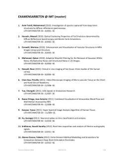
Consider the downlink model in Fig. 1 where, an LTE
MC and K SCs share the same frequency band, with no
cooperation. The LTE MC is composed of a Macro-cell Base
Station (MBS) and M User Equipments (MUEs). We assume
that Small-cell Access Points (SAPs) may communicate over
an infinite backhaul capacity, realizing a fully coordinated
network Multiple Input Multiple Output (MIMO). Nonetheless, we remark that the two tiers are totally independent
and disconnected, and hence they are not parts of a MultiUser MIMO (MU-MIMO) system [10]. For simplicity, but
without loss of generality, we consider that each SC hosts
only one single antenna Small-cell User Equipment (SUE).
We note that, a multi-SUE extension could be easily obtained
adopting techniques as the ones described in [10]. Throughout
Useful signal
Interference
No Interference
Figure 1.
Macro Cell
Small Cells
MU-VFDM downlink model, two-tiered network.
this work, subscript "m" refers to the MC, while "s" refers to
(i,j)
(i,j)
the SCs, i.e., hsm (or Hsm ) denotes a link from SAP i to
([i],j)
[i]
MUE j. s (or Hsm ) denotes a vector/matrix related to
the transmission from any SAP except i. All channel vectors
(·,·)
hab ∈ CN (0, IL+1 /(L + 1)) represent the impulse response
of independent and identically distributed (i.i.d.) frequencyselective Rayleigh fading channels composed of L + 1 paths.
Both systems adopt a block transmission scheme. An M user OFDMA based transmission of block size N + L, of
which L is the length of the cyclic prefix, is adopted in the
MC. As such, each MUE and SUE discards the leading L
symbols and performs a Discrete Fourier Transform (DFT).
Conceptually, the only distinction between an MUE and a
SUE, is the connection to the respective MBS/SAP. For the
MC, a uniform resource allocation is adopted, i.e., N/M
subcarriers per MUE. Let [·]m,n denote a matrix element at
the mth row and the nth column. We define Bj as the mask
filter used by MUE j to select its allocated subcarriers, s.t.
[Bj ](n,n) = 1 if the subcarrier n is allocated to the MUE j
and zero otherwise.
Let ⊗ denote the Kronecker product, IN the identity matrix
of size N, and F ∈ C N ×N a unitary DFT matrix with
kl
[F](k+1,l+1) = √1N e−i2π N for k, l = [0, N − 1]. We define
(1)T
(M )T
sm , [sm , . . . , sm ]T as the overall MC transmit vector of
(1)T
(K)T T
size N. Similarly, we define ss , [ss , . . . , ss
] as the
overall SC transmit vector, whose size will be discussed later.
(j)
(j)
Let ym , ys be the received signal at the jth MUE/SUE,
of dimension N and KN respectively. As a consequence,
M
X
(j)
ym
is the overall received vector at the MUEs
ym =
j=1
(1)T
(K)T
of size N and ys , [ys , . . . , ys
]T , the overall received
vector at the SUEs obtained by aggregating each single user
component. We can write
ym
= Hmm sm + Hsm Ess + Fnm
ys
=
(1)
Hss Ess + Hms sm + (IK ⊗ F)ns ,
where E is the MU-VFDM precoder, constructed by the
SAPs to cancel the interference from the SCs to the MC
as detailed further ahead. In (1), nm ∈ N C(0, σn2 IN ) and
ns ∈ N C(0, σn2 IKN ) are the thermal noise vectors.
The equivalent channel matrix for the MC, Hmm ∈ C N ×N ,
is obtained by summing up all the contributions of the MUEs.
M
X
−1
Consequently, Hmm =
Bj FT (h(1,j)
, where, F−1
mm )AF
j=1
is the Inverse DFT (IDFT) matrix at the MBS, A is a
(·,·)
(N + L) × N cyclic prefix insertion matrix and T (hmm ) ∈
(·,·)
C N ×(N +L) is a Toeplitz matrix constructed from the hmm
channel coefficients as done in [8].
(i,j)
(i,j)
Now, let Hss = T (hss ) be the N × (N + L) matrix
representing the link from the SAP i to the SUE j. By defining
(1,1)
(1,K)
Hss
· · · Hss
(2,1)
(2,K)
Hss
· · · Hss
0
,
(2)
Hss =
..
..
..
.
.
.
(K,1)
(K,K)
Hss
· · · Hss
we can write the overall equivalent SAPs to SUEs channel,
as Hss = (IK ⊗ F)H0ss ∈ C KN ×K(N +L) . We follow a
similar approach for the interfering link from the MBS to
(1,1)
(1,K) T
the SUEs. Then, H0ms = [Hms
, H(1,2)
] , where
ms , ..., Hms
(1,j)
(1,j)
−1
N ×N
Hms = T (hms )AF
∈ C
is the interfering link
from the MBS to the SUE j. As before, the overall equivalent
channel is Hms = (IK ⊗ F)H0ms ∈ C KN ×N . To represent
the overall interfering link from the SAPs to the MUEs,
Hsm ∈ C N ×K(N +L) , we proceed as done above for Hmm .
First, the equivalent channel from each of the SAP to the
M
X
MUEs is constructed, in the form H(i,·)
Bj FT (h(i,j)
=
sm
sm ).
j=1
Then, the overall interfering link matrix from the SAPs to the
(i,·)
MUEs is obtained
by aggregating
h
i Hsm , where i ∈ [1, K],
(1,·)
(K,·)
as Hsm = Hsm
. To cancel the interference
, . . . , Hsm
towards the MC, adhering to the overlay cognitive paradigm,
the MU-VFDM precoder E must satisfy the interference
cancelation constraint given by
Hsm E = 0,
(3)
where E is defined as
E=
K
M
Ei .
(4)
i=1
L
In (4),
is the direct sum operator [11] applied to the K
precoders used by the SAPs. Note that, for the condition (3)
to be fulfilled, E must span the null space of Hsm . At this
stage, we assume that no cooperation between the SAPs is
required to design E. Then, (3) is satisfied if the following
holds
H(i,·)
∀i ∈ [1, K].
(5)
sm Ei = 0
Therefore, we can focus on a single SAP i at a time, designing
a precoder Ei able to satisfy (5), and thus, (3). This allows
the precoder computation to be carried out disjointly by the
SAPs, resulting in a simpler architecture and lower signaling
(i,·)
through the backhaul. Let Hsm = LQ be its LQ decomposition. By definition, L ∈ C N ×(N +L) is a lower triangular
matrix and Q ∈ C (N +L)×(N +L) is an orthogonal matrix. By
construction, rank(H) ≤ N , thus we can find at least the last
(i,·)
L orthonormal columns of QH lying onto the kernel of Hsm .
Then, by defining
i
h
H
H
(6)
Ei , qH
|
·
·
·
|
q
|
q
N +1
N +L ,
(N +L)−1
we constuct a precoder that fulfills (5). We remark that a
(i,·)
perfect knowledge of Hsm is needed to achieve the nulling
condition in (3). In Secs. IV and V we discuss the effect of
imperfect CSI on the performance of both the MC and SC
systems.
Considering the structure of Ei , note that each SAP i faces
a dimensionality constraint. Consequently, by aggregating the
(i)
K individual zero mean, unit norm symbol vectors ss , of
dimension L, the overall SC transmit vector ss has dimension
KL.
Such a precoder projects the signal over the null-space of the
interfering link as done in Vandermonde-subsapce Frequency
Division Multiplexing (VFDM) [12]. The multi-user SC system exploits the left-over resources by the MC, represented by
the redundancy introduced by the MBS to combat inter block
interference (e.g., cyclic prefix), to transmit without generating
interference to the legacy system. The reader is advised to refer
to [12], [8], and references therein, for more details.
III. MU-VFDM P RECODER D ESIGN
The MU-VFDM precoder assures a harmless coexistence
between the SCs and the MC. Nevertheless, the precoder E
does not deal with the multi-user interference generated in
the SCs. In [9], by exploiting the full coordination among the
SAPs, we proposed a practical transmit scheme to deal with
the multi-user interference at the SC system. For clarity, let
e ss = Hss E,
H
(7)
of dimension KN × KL. To overcome the dimensionality
issue, and to be able to perform a regularized inverse beamforming (RIBF) [13], we introduced the load rate, i.e., the
ratio between the number of dimensions at the transmitter and
the ones at the receiver as
ψtx
β=
.
(8)
ψrx
RIBF is feasible when β ≥ 1. Let ψtx = γtx L and ψrx =
γrx N , where γtx , γrx ∈ N? are parameters related respectively
to the transmitter and receiver (e.g. SC density, number of
antenna at the receiver/transmitter), while N and L are fixed
due to the OFDMA symbol structure. Let us ∈ C γrx KN ×1 be
a new aggregate SC transmit vector, such that
ss = Φus ,
(9)
where Φ ∈ C γtx KL×KN is the RIBF precoder, defined as
σn2
H
(10)
IKN + Hss Hss ),
Ps
q
p
and normalized by EΦ = tr(ΦΦH ), s.t. tr(ΦΦH ) = 1.
The signal model (1) now reads
H
Φ = Hss (
ym
= Hmm sm + Fnm
ys
= Hss Wus + Hms xm + νs ,
(11)
where W = EΦ ∈ C γtx K(N +L)×KN is the overall precoder.
Now, ss has dimension γtx KL, E ∈ C γtx K(N +L)×γtx KL ,
e ss ∈ C γrx KN ×γtx KL , Hsm ∈ C N ×γtx K(N +L)
which yields H
γrxKN ×1
and ys ∈ C
.
IV. C HANNEL ESTIMATION PROTOCOL
One of the main issues related to a MU-VFDM practical
implementation is the robustness against imperfect CSIT. A
study of its performance under this assumption has to be
performed to validate the proposed technique. In this section,
we aim to take a step further in this direction by devising a
practical channel estimation protocol for the SAPs, to be used
in a realistic MU-VFDM implementation. The infinite backhaul capacity assumption made in Sec. II allows us to isolate
the effect of a bad channel estimation onto the performance
of the two-tiered network. The impact of the quantization of
the CSI when the network operates under limited backhaul
capacity will be the subject of future research. Note that,
at the primary system, the LTE specifications mandate performance requirements for the transmission, but let complete
freedom in channel estimation implementation [14]. Moreover,
in [15] and reference therein, it is shown that, to cope with
the aforementioned requirements in a practical scenario, the
MUEs will likely need to adopt a precoder based transmit
strategy, thus one of the possibilities is that an uplink channel
estimation be performed. Therefore, even though different
from a standard pilot-based approach, we assume that a 2steps channel estimation procedure based on preamble-training
symbols [14] is performed in the MC, as depicted in Fig. 2:
a) Uplink (UL) channel estimation, where the MUEs send
OFDM training symbols, and the MBS estimates the channel;
b) Downlink (DL) channel estimation, where the MBS sends in
the downlink OFDM training symbols, and the MUEs estimate
the channel. Considering a block fading channel of coherence
time T , we suppose that channel estimation in the MC is
performed during τ ≤ T . Therefore, T − τ is the available
time for transmission, before new channel estimations are
required. In the following, we will focus on the SC system
channel estimation protocol. For simplicity, we divide τ into
two phases, τ1 and τ2 : the UL channel estimation phase,
during τ1 , and the DL channel estimation phase, during τ2 .
A graphical representation of the estimation and transmission
times is provided in Fig. 3.
(i,j)
b (i,j)
Hsm = Bj FT (h
sm ) is computed and the precoder Ei is
derived, according to the procedure described in Sec. II.
B. DL channel estimation (τ2 )
(a) UL
During τ2 , as depicted in Fig. 2(b), training symbols are
transmitted simultaneously in both MC and SCs. From the
point of view of the MC, the MBS transmits to the MUEs a
unit norm Walsh-Hadamard (W-H) sequence [16] xm of length
τ2 at each subcarrier. Note that, τ2 size depends on the number
of both subcarriers and performed channel estimations. This
(1,j)
is done to allow Hmm to be known at the j th MUE, for the
equalization of the received signal during data transmission.
The structure of the received signal is the same for each MUE,
hence we focus on j th MUE and write
(b) DL
Figure 2.
Channel estimation phases.
τ
τ1
τ2
transmission time
T
Figure 3.
t
Channel estimation and transmission times.
(1,j)
(j)
ym
(t) = H(1,j)
mm Xm + Υm (t),
(14)
where
A. UL channel estimation (τ1 )
Xm
During τ1 , as depicted in Fig. 2(a), the MUEs transmit
OFDM training symbols used by the MBS to estimate the
channels and perform downlink resource block allocation and
input power optimization. Note that, each transmitted training
symbol is received by both the MBS and the SAPs. We assume
that, in this phase, the transmission is slotted in time, thus
τ1 is divided into M slots. Therefore, each MUE transmits
during a time slot of length τ1 /M . Consider the SC system,
in the following we show how the CSIT w.r.t. the interfering
link towards the MUEs can be acquired. Since the interference
cancelation precoder is computed disjointly by the SAPs, then
we can focus on a single SAP to describe the procedure. The
received signal at SAP i from MUE j is
(i)
ys(j,i) (t) = H(j,i)
ms xm + νs (t),
where xm =
(j,i)
Hms
√1
N
(12)
[1, . . . , 1] is a unit norm training symbol vec(j,i)
tor,
= FT (hms )AF−1 is the overall diagonal matrix
(j,i)
(i,j)
and t is time. Due to channel reciprocity, Hms = Hsm , and
(i,j)
b
the channel estimation Hsm is given by
h
b (i,j)
H
sm
i
=
n,n
=
τ1
√
M
M N X h (j,i) i
ys (t)
τ1 t=1
n
h
(i,j)
Hsm
i
τ1
√
M
M N X h (i) i
+
νs (t) . (13)
τ1 t=1
n,n
n
iT
h
b (i,j)
b (i,j)
b = F−1 [H
be the time
Let g
sm ]1,1 , . . . , [Hsm ]N,N
(i,j)
b
domain version of Hsm . Then, by taking the first L + 1
b, each corresponding to the number of paths
components of g
in the considered channel model, we define
b (i,j) , [b
bL+1 ]T .
h
g1 , . . . , g
sm
th
b (i,j)
The ith SAP can finally construct T (h
sm ) during the j
time slot in τ1 . We assume that, at this point, each SAP is
aware of the resource block allocation performed by the MBS.
Using this information, the ith SAP can construct Bj . Then,
Υ(j)
m (t)
T
[ xm | · · · | xm ] and
h
i
(j)
= F ν (j)
(1)
|
·
·
·
|
ν
(τ
)
2
m
m
=
are of size (N × τ2 ). At the end of τ2 , the j th MUE estimates
the channel to the MBS as
h
i
h
i
(1,j)
T
b (1,j)
H
=
y
(t)X
mm
m
m
n,n
n,n
h
i
h
i
(1,j)
T
= Hmm
+ Υ(j)
. (15)
m (t)Xm
n,n
n,n
Note that (15) is only possible due to the property of W-H
b (1,j)
as
sequences Xm XTm = I. Then, we proceed to find h
mm
(1,j)
b
done for hsm in Sec. IV-A.
Turning our focus back to the SC system, we recall that its
cognitive capabilities and the similarity between an MUE and
an SUE allow us to assume that the SUEs know the physical
layer characteristics of the MC. It is clear from (10) that, to
design the Φ precoder, the SAPs need to know the CSI with
respect to each SUEs. As depicted in Fig. 2(b) each SUE
transmits training symbols to the SAPs for channel estimation
purposes. For simplicity, we assume that all SUEs transmit in
a synchronized fashion. Techniques to allow this synchronized
transmission or the effects of asynchronous transmission are
out of the scope of this work and will be dealt in the future.
To avoid interference towards the MUEs, the SUEs make
use of the structure of the pilot symbols used in the channel
estimation process into the MC. By definition of xm , τ2 − 1
orthonormal W-H sequences can be found. Therefore, for
K ≤ (τ2 − 1), up to τ2 − 1 SUEs can select a unique W(i)
H sequence xs as its training symbols, such that
x(i)T
xm = 0, ∀i ∈ [1, K].
s
We note that, this approach is scalable only up to K ∼ N
SAPs/SUEs. On the other hand, if we consider the parameters
of a realistic operative scenario (i.e., N ∼ α∗10{2,3} , α ∈ Z+ ),
we can easily see that a scalability issue would arise only in
practical network deployment involving an unlikely number
of SAPs. Moreover, at this stage, we do not impose any
mechanism to chose the W-H sequences in the SC network.
Depending on the designer’s goal, one of the many schemes
proposed in the literature, i.e. [17], [18], could be adopted.
The received signal during τ2 at the j th MUE is
(1,j)
ym
(t)
H(1,j)
(16)
mm Xm +
K
X
−1 (j)
Bj FT (h(i,j)
Xs + Υ(j)
sm )F
m (t),
=
i=1
h
i
(j)
(j)
where
= Bj F ν m (1) | · · · | ν m (τ2 ) , and
the estimate of the channel is given as in (15), since
PK
(i,j)
−1 (j) T
Xs Xm = 0. Hence, no interference
i=1 Bj FT (hsm )F
is generated from the SUEs towards the MUEs.
The received signal from the SUEs at the j th SAP is
(j)
Υm (t)
ys(·,j) (t)
=
K
X
(i)
H(i,j)
ss Xs +
(17)
i=1
be the sum-rate for the MC and SCs respectively, when perfect
CSIT is available, where ρ denotes the Signal to Interference
plus Noise Ratio (SINR). As a result of the relaxation of
the perfect CSIT assumption at the SAPs, the interference
cancelation constraint in (3) is not fulfilled anymore and
the MUEs suffer interference from the SAPs’ transmission,
translated into a sum-rate loss. For the SC system, the precoder
W is based on an imperfect channel estimation affecting the
achievable sum-rate of the SC system, because of multi-user
interference. From [20], we know that, given the SINR for the
perfect CSIT, we can define an effective SINR value as
ρeff =
N
th
and, since the j SAP needs an estimate of the channels
towards each SUE, then it performs K different channel
(i,j)
estimations to find Hss , ∀ i ∈ [1, K]. We focus on the link
th
connecting the j SAP and ith SUE, the remaining channels
are estimated similarly. Due to the previous consideration in
(i)
the SC system, we assume that the j th SAP knows Xs , ∀ i ∈
(i,j)
b ss is given by
[1, K]. Therefore, H
b (i,j)
H
ss
i
n,n,
i
ys(·,i) (t)X(i)T
s
h
i
hn,n
i
(i)T
= H(i,j)
+
Υ(j)
ss
s (t)Xs
=
h
n,n
(1,j)
(j)
n,n
, (18)
(i)T
since FT (hms )F−1 Xm Xs = 0. Again, due to the use of
the W-H training symbols, no interference is generated from
b (i,j)
the MBS towards the j th SAP. We proceed to find h
as
ss
done for in Sec. IV-A. Finally, at the end of τ2 , the precoder
W can be constructed, as described in Sec. III. After the
channel estimation phase τ , both systems can engage in the
transmission phase during T − τ .
V. N UMERICAL RESULTS
In this section, we illustrate the impact of the channel
estimation protocol on the performance of MU-VFDM. In the
Monte Carlo simulations, we consider an OFDMA MC system
downlink with M = 4 MUEs, characterized by N = 32 active
L
= 14 is
subcarriers, cyclic prefix of length L = 8. The ratio N
peculiar to the extended mode of a typical LTE configuration
[19], and the values of N ,L have been chosen merely to
provide feasible computational time. In the SC system we
consider K = 3 SAPs/SUEs with a load rate β = 1. Noise
and channel vectors are generated as described in Sec. II.
Let
N
1 X
SUM, P
log2 (1 + ρi ) and
(19)
Cm
=
N + L i=1
CsSUM, P
=
γrx
KN
X
1
log2 (1 + ρi )
N + L i=1
(21)
where we assume equal transmit power for training and data
symbols. Therefore, let
−1
FT (h(1,j)
Xm + Υ(j)
ms )F
s (t),
h
ρ2 τ
,
1 + (1 + τ )ρ
(20)
CmSUM, I
=
T −τ X
log (1 + ρeff,j ) and
T (N + L) j=1 2
CsSUM, I
=
T −τ X
log (1 + ρeff,j )
T (N + L) j=1 2
KN
be the sum-rate of the MC and the SCs respectively, when the
proposed channel estimation protocol is adopted. Note that, at
this stage, we do not consider any interference from the MBS
to the SUEs, in order to be able to evaluate the effect of the
imperfect channel estimation at the SAPs.
In Fig. 4, the ratio between the rate obtained with imperfect
CSIT and the rate obtained with perfect CSIT, is computed for
the MC and the SC system, as different τ /T proportions are
chosen for SNR ∈ {0, 10, 20} dB. The optimal τ is dependent
on the SNR in both cases. For the MC, we notice that, for
medium and high SNR values, the sum-rate scales nearly linear
with the pre-log factor, hence the best performance is achieved
for the minimum value given the considered parameters,
τ = 0.08T . In general the performance for different SNR
values is very similar. On the other hand, for the SC system,
a bigger training time results always in a power gain, thus
the optimal τ is always different. Moreover, by comparing the
two systems we can see that a worse CSIT affects mainly
the sum-rate of the SC system, penalized especially at very
low SNR. In fact, the RIBF precoder adopted in MU-VFDM
is very sensitive to channel estimation errors, hence the SC
system performance is strongly dependent on the SNR values.
In Fig. 5 the SNR is kept constant at 15 dB, while the load
rate β ∈ {1, 1.5, 2}. Conversely, in Fig. 6, three subcarriers
values are tested, N ∈ {24, 32, 40}. In both cases the
technique shows almost constant performance for the MC,
where the optimal τ corresponds to the minimum value. The
SCs rate-loss is more evident and, in general, the bigger N the
worse the performance. Nevertheless, the simulation shows a
clear improvement as the network becomes more dense (i.e.,
bigger β), thus, in order to guarantee a good sum-rate to the
SCs, a trade-off between N and β is likely to be found.
1
SNR = 5 dB
SNR = 15 dB
SNR = 25 dB
Ratio MC
0.8
0.6
0.4
0.2
0
0.1
0.2
0.3
0.4
0.5
0.6
0.7
τ
T
0.8
SNR = 5 dB
SNR = 15 dB
SNR = 25 dB
Ratio SC
0.6
0.4
0.2
0
0
0.1
0.2
0.3
0.4
0.5
0.6
0.7
τ
T
Figure 4. Ratio between the rate obtained with imperfect CSIT and the rate
obtained with perfect CSIT for MC and SC system as SNR changes.
0.8
β=1
β = 1.5
β=2
Ratio MC
0.6
0.4
0.2
0
0.1
0.2
0.3
0.4
0.5
0.6
0.7
0.8
0.9
1
τ
T
0.8
β=1
β = 1.5
β=2
Ratio SC
0.6
0.4
0.2
0
0.1
0.2
0.3
0.4
0.5
0.6
0.7
0.8
0.9
1
τ
T
Figure 5. Ratio between the rate obtained with imperfect CSIT and the rate
obtained with perfect CSIT for MC and SC system as β changes.
Ratio MC
1
N = 24
N = 32
N = 40
0.8
0.6
0.4
0
0.1
0.2
0.3
0.4
0.5
0.6
0.7
τ
T
0.7
N = 24
N = 32
N = 40
Ratio SC
0.6
0.5
0.4
0
0.1
0.2
0.3
0.4
0.5
0.6
0.7
τ
T
Figure 6. Ratio between the rate obtained with imperfect CSIT and the rate
obtained with perfect CSIT for MC and SC system as N changes.
VI. C ONCLUSION
In this work, we have revisited a dynamic spectrum access
overlay technique called MU-VFDM. This technique allows
the deployment of SCs inside of an MC, while generating
no interference to the latter at the cost of perfect CSIT at the
SAPs. In the current work, we have moved one step closer to a
realistic setting, by relaxing the perfect CSIT assumption. With
that in mind, we have devised a suitable channel estimation
protocol, taking into consideration the requirements of MUVFDM’s cascaded precoder structure. As expected, analysis
of the sum-rate shows that imperfect CSI incurs a loss at
both systems. Then, the best compromise between training
and data symbols has been discussed. The results presented
herein reinforce our previous findings that MU-VFDM can be
used to allow the coexistence of future SCs and MCs inside
the same coverage area, sharing the same band.
The study of other implementation issues of MU-VFDM
is an ongoing work. A finite backhaul capacity and clustered
cooperation between the SAPs will be considered. Moreover,
we plan to study how synchronization issues, critical aspect in
a cognitive radio framework, can impact on the performance
of both systems. All these results will allow the further implementation of a transmission testbed based on MU-VFDM to
prove its effectiveness as a candidate for the future deployment
of SCs.
R EFERENCES
[1] H. Holma and A. Toskala. LTE for UMTS OFDMA and SC-FDMA
Based Radio Access. 2009.
[2] J. Hoydis, M. Kobayashi, and M. Debbah. Green small-cell networks.
IEEE Vehicular Technology Magazine, 6(1):37–43, 2011.
[3] Alcatel Lucent. Lightradio: Evolve your wireless broadband network
for the new generation of applications and users. [Online] Available:
http://www.alcatel-lucent.com/features/light_radio/index.html, 2010.
[4] A. Goldsmith, S.A. Jafar, I. Maric, and S. Srinivasa. Breaking spectrum
gridlock with cognitive radios: An information theoretic perspective.
Proceedings of the IEEE, 97(5):894–914, 2009.
[5] W. Zhang and U. Mitra. Spectrum shaping: A new perspective on
cognitive radio (part I): Coexistence with coded legacy transmission.
IEEE Transactions on Communications, 58(6):1857–1867, 2010.
[6] Y. Ma, D.I. Kim, and Z. Wu. Optimization of OFDMA-based cellular
cognitive radio networks. IEEE Transactions on Communications,
58(8):2265–2276, 2010.
[7] S. Haykin. Cognitive radio: brain-empowered wireless communications.
IEEE Journal on Selected Areas in Communications, 23(2):201–220,
2005.
[8] L.S. Cardoso, M. Maso, M. Kobayashi, and M. Debbah. Orthogonal
LTE two-tier cellular networks. In IEEE International Conference on
Communications, 2011.
[9] M. Maso, L. Cardoso, M. Debbah, and L. Vangelista. Orthogonal
precoder for two-tiered networks. submitted for publication.
[10] D. Gesbert, M. Kountouris, R. W. Heath Jr., C.-B. Chae, and T. Salzer.
Shifting the MIMO paradigm: From single user to multiuser communications. IEEE Signal Processing Magazine, 24(5):36–46, 2007.
[11] F. Jr. Ayres. Theory and Problems of Matrices. Mcgraw-Hill, 1967.
[12] L.S. Cardoso, M. Kobayashi, Ø. Ryan, and M. Debbah. Vandermonde
frequency division multiplexing for cognitive radio. In Proceedings
of the 9th IEEE Workshop on Signal Processing Advances in Wireless
Communications, 2008.
[13] C.B. Peel, B.M. Hochwald, and A.L. Swindlehurst.
A vectorperturbation technique for near-capacity multiantenna multiuser communication (part I): channel inversion and regularization. IEEE Transactions on Communications, 53(1):195–202, 2005.
[14] S. Sesia, I. Toufik, and M. Baker. LTE – The UMTS Long Term
Evolution. 2009.
[15] D. Grieco, J-L. Pan, R. Olesen, and N. Shah. Uplink single-user MIMO
for 3GPP LTE. In IEEE 18th International Symposium on Personal,
Indoor and Mobile Radio Communications, 2007.
[16] H.F. Harmuth. Transmission of Information by Orthogonal Functions.
Springer; 2nd ed., 1972.
[17] E. Alsusa and C.; Masouros. Adaptive code allocation for interference
management on the downlink of DS-CDMA systems. IEEE Transactions
on Wireless Communications, 7(7):2420 – 2424, 2008.
[18] Y. Zhou, J. Wang, and T.-S. Ng. Downlink transmission of broadband
OFCDM systems - part V: Code assignment. IEEE Transactions on
Wireless Communications, 7(11):4546–4557, 2008.
[19] 3GPP TR 25.814, Physical Layer Aspects for Evolved UTRA, v.2.0.0.
3GPP, 2006.
[20] B. Hassibi and B. Hochwald. How much training is needed in multipleantenna wireless links? IEEE Transactions on Information Theory,
49(4):951–963, 2003.


© Copyright 2026