
A Novel Guidance Law with Line-of-Sight Acceleration Feedback for
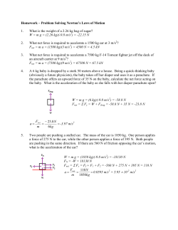
A Novel Guidance Law with Line-of-Sight Acceleration Feedback for Missiles against Maneuvering Targets Kemao Ma, Xiaoyu Zhang Abstract Terminal guidance law design and its implementation are considered for homing missiles against maneuvering targets. The lateral acceleration dynamics are taken into account in the design. In the guidance law design, the ling-of-sight acceleration signals are incorporated into the acceleration reference signals to compensate for the targets’ maneuvers. Then the commanded accelerations are designed and the convergent tracking of the lateral accelerations to these signals is proven theoretically. In the guidance implementation, a linear high-gain differentiator is used to estimate the line-of-sight rates and the line-of-sight acceleration signals. To avoid the magnifying effects of higher order differentiation, a practical design of commanded accelerations is given to realize approximate tracking of the lateral accelerations to the given reference signals. Simulation is conducted for both cases with and without measurement noises. The simulation results justify the feasibility of the design and the implementation. Keywords: homing missiles, maneuvering targets, guidance law implementation. I. I NTRODUCTION For terminal guidance laws of the homing missiles against maneuvering targets, two of the most important factors affecting the guidance precision are the targets’ maneuvers and the lateral acceleration dynamics of the missiles[1]. If these two factors are ignored in mathematical performance analysis, then the conventional proportional navigation guidance (PNG) laws, which provide for missiles lateral acceleration commands proportional to the line-of-sight rates, are optimal in the sense that both the miss distance and control efforts are accounted for in the performance cost functional[2]. This result motivated many guidance laws based on PNG. For a maneuvering target, an augmented PNG law consists of conventional PNG and a compensation term for the target’s maneuvering acceleration. Thus, the target’s maneuver is canceled out in the relative kinematics of the missile and the target, and the performance of PNG against a non-maneuvering target is recovered. Since the target’s maneuver is generally unknown, the remaining problem is how to estimate the target’s maneuver in guidance law implementation. For a seeker with bearing only measurement, such as an infrared seeker, the acceleration components of the target’s maneuver are not observable. Therefore, Kalman Filter technique, as well as conventional state observer technique, would be practical only if an appropriate maneuvering model for the target’s maneuver was designed for the observability condition to be met[3]. By extending the observer states, however, extended state observer technique can be used to estimate the target’s maneuver without making any a priori assumptions on target’s maneuver[4][5]. In fact, extending the observer states is equivalent to a constant acceleration (CA) model being adopted, and the discrepancy between the actual target’s maneuver and the output of the CA This work was supported in part by the National Natural Science Foundation of China under grant numbers 61174001, 61321062. Kemao Ma is with the Control and Simulation Center, School of Astronautics, Harbin Institute of Technology, Harbin, China, 150080. China. [email protected] Xiaoyu Zhang is with Automation College, Harbin Engineering University, Harbin, China, 150001. Corresponding author. [email protected] model is treated as an uncertain term in the observer error dynamics and is suppressed via high-gain feedback. Thus no further delicate models of the target’s maneuver are necessary. The compensation for the targets’ maneuvers is a feed-forward method. The targets’ maneuvers can also be treated in a feedback paradigm. In this case, the maneuvers of the targets are thought of as external disturbance inputs for the guidance systems, and feedback control methods with good disturbance rejection, or attenuation, can be used to design the guidance laws. Indeed, based on sliding mode control, various guidance laws are designed in which a switching term is added to the PNG term[6][7]. The sliding-mode guidance laws are non-smooth, which may result in theoretical difficulties in guidance law implementation when the lateral acceleration dynamics of the missiles are considered. Both theoretical analysis and numerical simulation show that the lateral acceleration dynamics of the missiles can induce miss distance, especially when the time constants are large. There are two approaches to solving this problem. One approach is to improve the response characteristics of the lateral acceleration dynamics by adopting novel techniques such as lateral jets[8], and the guidance and control systems are in a decoupled structure and designed in separately. The introduction of the lateral jets endows the missiles with features of heterogeneous multiple actuators and substantial uncertainties due to the side jet interaction effects[9], which bring potential difficulties in the design of the guidance and control systems. The other approach is to conduct an integrated design of guidance and control[10]. In an integrated design, the guidance, control and guidance information estimation are treated as a whole coupled system for which certain performance index is to be optimized. The integrated system is quite complex with multiple constraints compared with the guidance system or the control system in a decoupled structure, and there are still difficulties to be tackled in both theory and application. In this paper, a novel guidance law is designed for missiles against maneuvering targets. In the guidance law, the target’s maneuvers are compensated for via incorporating the line-of-sight accelerations into the guidance commands, instead of constructing a filter or an observer. Also incorporated into the commands are the dynamics of the missiles via a robust control design. The idea is to design the guidance and control separately, then to redesign the lateral acceleration commands issued by the guidance laws by incorporating the closed-loop lateral acceleration dynamics into the commands. By so doing, a high guidance precision is reached. The rest of the paper is organized as follows. In Section II, the three-dimensional relative kinematics of a missile and its maneuvering target are given, and the problem of terminal guidance law design is formulated. In Section III, a guidance law is designed via incorporating into guidance commands the line-of-sight accelerations and the lateral acceleration dynamics of the missile. In the following section, guidance law implementation is considered, and a practical design of the acceleration commands is given. In Section V, numerical simulation is conducted. The conclusion is given in Section VI. II. P ROBLEM F ORMULATION We assume the terminal guidance scenario of a missile against a maneuvering air target. It is convenient to describe the kinematics of the relative motion between the missile and its target in the line-of-sight coordinate system, denoted by OxL yL zL and shown in Fig. 1. The origin O of OxL yL zL is set to the mass center of the missile (denoted by M); the axis OxL is aligned with the line-of-sight (denoted by LOS), the half-line originated from O and pointing to the target (denoted by T); the axis OyL is in the vertical plane, pointing upward and normal to OxL ; and the axis OzL is normal to both OxL and OyL with its positive direction decided by the right-hand rule. We take the earth-fixed coordinate system Axyz as an inertial reference. OxL yL zL can be obtained through a translation of Axyz, followed by two consecutive counterclockwise rotations, first with an Euler angle qβ with respect to Ay, and second with an Euler angle qε with respect to OzL , as shown in Fig. 1 where, for clarity of illustration, the origin A of Axyz is already translated to coincide with the origin O of OxL yL zL , and the rotations are indicated with dotted curved arrows. Thus, the orientation of OxL yL zL with respect to Axyz is characterized by qε and qβ , known as line-of-sight angles. The relative range vector, i.e. the radius vector of the target in OxL yL zL originating from M towards T along LOS, is denoted by ⃗R, and its magnitude, the relative range, is denoted by R. y yL T xL R LOS q q q O( A) M x q z zL Fig. 1. Orientation of OxL yL zL with respect to Axyz Next, we construct the mathematical description of the relative motion of the missile and the target in OxL yL zL . Denote the respective unit vectors of OxL , OyL , and OzL by ⃗iL , ⃗jL , and ⃗kL , and we have ⃗R = R⃗iL + 0⃗jL + 0⃗kL , (1) Denote the unit vectors of Ax, Ay, and Az by ⃗i, ⃗j, and ⃗k, respectively. Fig.1 shows that ⃗iL ⃗i ⃗ jL = L(qε , qβ ) ⃗j , ⃗kL ⃗k where cos qε sin qε 0 cos qβ 0 L(qε , qβ ) = − sin qε cos qε 0 0 1 0 0 1 sin qβ 0 sin qε − cos qε sin qβ cos qε cos qβ = − sin qε cos qβ cos qε sin qε sin qβ sin qβ 0 cos qβ (2) − sin qβ 0 cos qβ . Consider the two consecutive rotations shown in Fig. 1, and we have the expression of the angular velocity of OxL yL zL with respect to Axyz as follows ⃗ =q˙β ⃗j + q˙ε⃗kL ω =q˙β sin qε⃗iL + q˙β cos qε ⃗jL + q˙ε⃗kL , (3) where the latter equality is obtained using (2). The relative velocity between the missile and the target is ⃗R˙ =R˙⃗iL + ω ⃗ × R⃗iL =R˙⃗iL + Rq˙ε ⃗jL − Rq˙β cos qε⃗kL , (4) which further leads to ⃗R¨ =R¨⃗iL + R˙⃗i˙L + (R˙ q˙ε + Rq¨ε )⃗jL + Rq˙ε ⃗j˙L ˙ − (R˙ q˙β cos qε + Rq¨β cos qε − Rq˙β q˙ε sin qε )⃗kL − Rq˙β cos qε⃗kL , (5) where ⃗i˙L =⃗ ω ×⃗iL =q˙ε ⃗jL − q˙β cos qε⃗kL , ⃗j˙L =⃗ ω × ⃗jL = − q˙ε⃗iL + q˙β sin qε⃗kL , ⃗k˙ L =⃗ ω ×⃗kL =q˙β cos qε⃗iL − q˙β sin qε ⃗jL . Substitute these expressions into (5), and we have ⃗R¨ =(R¨ − Rq˙ε2 − Rq˙2 cos2 qε )⃗iL β + (2R˙ q˙ε + Rq¨ε + Rq˙2β sin qε cos qε )⃗jL + (−2R˙ q˙β cos qε + Rq˙ε q˙β sin qε − Rq¨β cos qε + Rq˙ε q˙β sin qε )⃗kL . (6) Denote the projections of the target’s acceleration on OxL , OyL , and OzL by aTr , aT ε and aT β , respectively, and denote the projections of the missile’s acceleration by a , a and a , respectively. Account for the contributions to ⃗R¨ of these projections, Mr Mε Mβ and we have ⃗R¨ = (aTr − aMr )⃗iL + (aT ε − aM ε )⃗jL + (aT β − aM β )⃗kL . (7) Equating (6) to (7) gives the following mathematical description of the relative motion between the missile and its target: R¨ =Rq˙ε2 + Rq˙β2 cos2 qε + aTr − aMr , 2R˙ aT ε − aM ε q˙ε − q˙β2 sin qε cos qε + , q¨ε = − R R aT β − aM β 2R˙ q˙ + 2q˙ε q˙β tan qε − . q¨β = − R β R cos qε (8) (9) (10) In equations (9) and (10), the target’s acceleration components aT ε and aT β are unknown and can be thought of as external disturbances. The acceleration components aM ε and aM β are provided by the missile acceleration dynamics which can be modeled as follows a¨M ε = − 2ζ ωn a˙M ε − ωn2 aM ε + ωn2 aM ε c + ∆ε (aM ε , a˙M ε ,t), (11) a¨M β = − 2ζ ωn a˙M β − ωn2 aM β + ωn2 aM β c + ∆β (aM β , a˙M β ,t), (12) where the dynamics are modeled as second-order linear dynamics with damping ratio ζ > 0 and natural frequency ωn > 0, and aM ε c and aM β c are guidance commands to be designed. The differences of the second-order models from the real dynamics of the missile are lumped into the uncertainties ∆ε (aM ε , a˙M ε ,t) and ∆β (aM β , a˙M β ,t) which satisfy, uniformly in t, the following inequalities |∆ε (aM ε , a˙M ε ,t)| 6 a¯M , (13) |∆β (aM β , a˙M β ,t)| 6 a¯M , (14) where a¯M is a known constant. Classical guidance theory shows that if the line-of-sight rates q˙ε and q˙β are convergent to zero, then a satisfactory miss distance can be guaranteed. Thus the guidance law design problem can be formulated as follows: With the existence of the external disturbances aT ε and aT β and uncertainties ∆ε (aM ε , a˙M ε ,t) and ∆β (aM β , a˙M β ,t) satisfying (13) and (14), design aM ε c and aM β c in equations (11) and (12) such that aM ε and aM β in equations (9) and (10) can make q˙ε and q˙β convergent to zero. III. G UIDANCE L AW D ESIGN BASED ON L INE - OF -S IGHT ACCELERATION F EEDBACK If the following equalities hold: aM ε =aT ε − 2R˙ q˙ε − Rq˙2β sin qε cos qε + kRq˙ε , (15) aM β =aT β + 2R˙ q˙β cos qε − 2Rq˙ε q˙β sin qε − kRq˙β cos qε . (16) where k is a positive constant, then equations (9) and (10) become q¨ε = − kq˙ε , (17) q¨β = − kq˙β , (18) Equations (17) and (18) guarantee the exponential convergence of the line-of-sight rates, and the convergence rates are determined by parameter k. Generally speaking, equalities (15) and (16) do not hold. However, if commanded acceleration components aM ε c and aM β c are designed such that the left-hand sides of (15) and (16), aM ε and aM β , can track the respective right-hand sides, then the dynamics of line-of-sight rates (17) and (18) will hold in an approximation sense. Thus the right-hand sides of (15) and (16) should be incorporated into aM ε c and aM β c as reference signals for aM ε and aM β to track. To deal with the unknown terms aT ε and aT β , we rewrite the equations (9) and (10) as Rq¨ε + aM ε =aT ε − 2R˙ q˙ε − Rq˙2β sin qε cos qε , aM β − Rq¨β cos qε =aT β + 2R˙ q˙β cos qε − 2Rq˙ε q˙β sin qε . (19) (20) Comparing the right-hand sides of (15) and (16) with those of (19) and (20) suggests taking the reference signals in the form of aM ε r =aM ε + Rq¨ε + kRq˙ε , (21) aM β r =aM β − Rq¨β cos qε − kRq˙β cos qε , (22) based on which the commanded accelerations are in the form of aM ε c =aM ε r + Kε , (23) aM β c =aM β r + Kβ , (24) where Kε and Kβ are yet to be designed. In (21) and (22) line-of-sight accelerations, q¨ε and q¨β , are used to compensate for the target’s unknown maneuvers. The compensation effect depends on the tracking of aM ε and aM β to the respective right-hand sides of (15) and (16). In the sequel, we design Kε (aM ε , a˙M ε ) and Kβ (aM β , a˙M β ) to guarantee the tracking, as well as to account for the uncertainties in (11) and (12). Define the tracking error vectors as [ eε = [ ]T eε 1 eε 2 ]T , aM ε − aM ε r a˙M ε − a˙M ε r [ ]T eβ = eβ 1 eβ 2 ]T [ = aM β − aM β r a˙M β − a˙M β r , = (25) (26) and, according to (11) and (12), we have the error dynamics as follows 1 ∆ε (aM ε , a˙M ε ,t)), ωn2 1 e˙β =Aeβ + B(aM β c − aM β r + fβ + 2 ∆β (aM β , a˙M β ,t)), ωn e˙ε =Aeε + B(aM ε c − aM ε r + fε + (27) (28) where 2ζ a˙M ε r a¨M ε r − 2 , ωn ωn 2ζ a˙M β r a¨M β r − 2 , fβ = − ωn ωn 0 1 0 , B = . A = ωn2 −ωn2 −2ζ ωn fε = − (29) (30) (31) Substitute (23) and (24) into (27) and (28), and we have 1 ∆ε (aM ε , a˙M ε ,t)), ωn2 1 e˙β =Aeβ + B(Kβ + fβ + 2 ∆β (aM β , a˙M β ,t)), ωn e˙ε =Aeε + B(Kε + fε + (32) (33) Since ζ > 0 and ωn > 0, A in (31) is a Hurwitz matrix. Therefore, for any Q > 0, there is a P > 0, such that the following Lyapunov equation holds: AT P + PA = −Q. (34) For error dynamics (32) and (33), define the Lyapunov function candidate asV = eTε Peε + eTβ Peβ , and we have V˙ =eεT (AT P + PA)eε + eβT (AT P + PA)eβ + 2eTε PB(Kε + fε + 1 1 ∆ε (aM ε , a˙M ε ,t)) + 2eTβ PB(Kβ + fβ + 2 ∆β (aM β , a˙M β ,t)). ωn2 ωn (35) Substitute (34) into (35) and consider (13) and (14), and we have V˙ 6 − eTε Qeε − eTβ Qeβ + 2eTε PB(Kε + fε ) + 2eTβ PB(Kβ + fβ ) + 2a¯M (∥PBeε ∥ + ∥PBeβ ∥). ωn2 (36) If we design Kε and Kβ as follows 2a¯M sign(BT Peε ), ωn2 2a¯M Kβ = − fβ − 2 sign(BT Peε ), ωn Kε = − fε − (37) (38) then from (36) we have V˙ 6 −eTε Qeε − eTβ Qeβ , which justifies the asymptotic convergence of error vectors eε and eβ . IV. G UIDANCE L AW I MPLEMENTATION Here we assume that the radar seeker of the missile can provide relative range, relative range rate, and line-of-sight angles for guidance law implementation. Since angular rates and accelerations of line-of-sight angles are used in the guidance law, the implementation is focused on numerical differentiation algorithms. Here we employ the following linear differentiator k1 (x1 − f (t)), ε k x˙2 =x3 − 22 (x1 − f (t)), ε k x˙3 = − 33 (x1 − f (t)), ε x˙1 =x2 − (39) (40) (41) where f (t) is the input signal to be differentiated, ε > 0 is a small design parameter, and k1 > 0, k2 > 0 and k3 > 0 are such that s3 + k1 s2 + k2 s + k3 (42) is a Hurwitz polynomial. Here we assume that the third order derivative of f is bounded, i.e., there exists a constant K f such that | f (3) (t)| 6 K f , ∀t. Define e1 e = e2 e3 = (43) x1 − f (t) ε2 x2 − f˙(t) ε2 x3 − f¨(t) , (44) and from (39) - (41) we have ε e˙ = Ae e + ε Be f (3) (t), where −k1 Ae = −k2 −k3 1 0 0 0 (45) 0 1 , Be = 0 . 0 1 Since (42) is a Hurwitz polynomial, A is Hurwitz. Therefore, for any given Qe > 0, there exists a P > 0, such that ATe P + PAe = −Qe . (46) Taking Ve (e) = eT Pe e, and it is easy to show that system (45) is input-to-state stable[11] with f (3) (t) thought of as an external input, and V˙ (e) 6 0 whenever ∥e∥ > 2ε ∥Pe Be ∥K f λmin (Qe ) . This means that the state of the system (45), the error defined in (44), will converge in finite time T (ε ), dependent on ε , to the following set { } 2ε ∥Pe Be ∥K f S(ε ) = e ∈ R3 ∥e∥ 6 , λmin (Qe ) (47) which is dependent on the parameter ε , and shrinks to zero as ε tends to zero from above. Thus for an input signal f satisfying (43), the error variables defined in (44) are bounded, and lim x1 (t) = f (t), (48) lim x2 (t) = f˙(t), (49) lim x3 (t) = f¨(t). (50) t→∞,ε ↓0 t→∞,ε ↓0 t→∞,ε ↓0 We can also see from (45) that the converging rates of (48) - (50) increase with the decrease of the value of ε : lim T (ε ) = 0, ε ↓0 and the bound K f in (43) can be arbitrarily large provided ε is small enough. However, with the decrease of ε , the error variables ei (t), i = 1, 2, 3, 0 < t < T (ε ) will become very large, known as the peaking phenomenon[12]. To attenuate the peaking with the set S(ε ) unchanged, we can introduce a satiation function to the differentiator (39) - (41). Here the details will not be discussed theoretically, but we note that numerical simulation we conducted has revealed the effectiveness of this technique. β We denote the state of the differentiator (39) - (41) by xiε , i = 1, 2, 3 when the input signal is qε , and by xi , i = 1, 2, 3 when the input signal is qβ . Therefore, the reference signals given in (21) and (22) are implemented by replacing q˙ε , q¨ε , q˙β , q¨β by β β x2ε , x3ε , x2 and x3 , respectively, provided R, qε and qβ are available. As far as measurement noises are concerned, we need to limit the order of differentiation operations as low as possible, especially to avoid very high order differentiations. Here only first and second order differentiations are necessary, and we can limit the effects of noises by limiting the value of the parameter ε . If we used the differentiator to implement Kε and Kβ in (37) and (38), the further differentiation operations on aM ε r and aM β r required in (29) and (30) would have significantly magnified the noises of the measured signals qε and qβ , since third and fourth order differentiations are involved. To avoid this, here we give a practical design of aM ε r and aM β r , instead of the theoretical design given in (37) and (38). The idea is to treat the bounded uncertainties ∆ε and ∆β as input signals to dynamics (11) and (12), and to reduce the gain of ∆ε and ∆β as well as to increase the frequency bandwidths of aM ε r and aM β r . Let 2ζ (K − 1) a˙M ε − (K 2 − 1)aM ε + (K 2 − 1)aM ε r , ωn 2ζ (K − 1) a˙M β − (K 2 − 1)aM β + (K 2 − 1)aM β r , Kβ = − ωn Kε = − (51) (52) where K > 1 is a design parameter, and substitute (51) and (52) into (11) and (12), and we have a¨M ε = − 2ζ (K ωn )a˙M ε − (K ωn )2 aM ε + (K ωn )2 aM ε r + ∆ε (aM ε , a˙M ε ,t), (53) a¨M β = − 2ζ (K ωn )a˙M β − (K ωn )2 aM β + (K ωn )2 aM β r + ∆β (aM β , a˙M β ,t). (54) We can see from (53) and (54) that the gains of uncertain input signals ∆ε and ∆β are reduced K 2 times, with the gains of aM ε r and aM β r unchanged and the bandwidths increased K times. Although Kε and Kβ in (51) and (52) cannot guarantee asymptotic convergence of aM ε and aM β to their respective reference signals aM ε r and aM β r , as guaranteed by (37) and (38), but a satisfactory tracking can be guaranteed provided K is sufficiently large. V. S IMULATION Here we consider the terminal guidance phase with the following initial conditions ˙ R(0) = 6000m, R(0) = 600m/s, qε (0) = 27◦ , q˙ε (0) = 1.5◦ /s, qβ (0) = 30◦ , q˙ε (0) = −1.25◦ /s. The sampling period of the guidance system is assumed to be T =5ms. Since the time horizon of a typical terminal guidance phase ranges over a time interval of several seconds or just over ten seconds, we can employ the Euler integration as the numerical implementation of differentiator (39) - (41) without much loss of precision, i.e. [ ] x1 (kT ) − f (kT ) x1 ((k + 1)T ) =x1 (kT ) + T x2 (kT ) − k1 sat( ) , Ks ε ] [ x1 (kT ) − f (kT ) x2 ((k + 1)T ) =x2 (kT ) + T x3 (kT ) − k2 sat( ) , Ks ε 2 ] [ x1 (kT ) − f (kT ) ) , x3 ((k + 1)T ) =x3 (kT ) + T −k3 sat( Ks ε 3 where the parameter Ks is set to 80, ε is set to 0.011, and the parameters k1 , k2 and k3 are set to 3, 3, and 1, respectively. All the initial values of the differentiator are set to zero. The parameters in the dynamics (11) and (12) are set to ζ = 0.7 and ωn = 8. The maximum acceleration the missile can provide is assume to be a¯M = 200m/s2 , and the commanded accelerations issued by the guidance system take the following form aM ε r + Kε ), a¯M aM β r + Kβ aM β c =a¯M sat( ), a¯M aM ε c =a¯M sat( where aM ε r and aM β r are given in (21) and (22) with k = 5, and Kε and Kβ are given in (51) and (52) with K = 4. The minimum range for the seeker to operate is assumed to be R¯ b = 100m, and when R < R¯ b , both aM ε c and aM β c are set to zero. Numerical simulation is conducted for the above scenario with an integration step 0.0001s. For a non-maneuvering target, the interception time is 10.0577s, and the miss distance is 0.0475m. Then we consider the case where the maneuver of the target takes the following form aT ε =100 sin(2π fε + θε )m/s2 , aT β =100 sin(2π fβ + θβ )m/s2 , where fε =0.35Hz, θε = π5 , fβ =0.5Hz, θβ = π5 . The interception time is 10.1039s, and the miss distance is 0.1343m. The lineof-sight rates q˙ε , q˙β and their respective estimates are shown in Fig. 2 and Fig. 3, and a satisfactory tracking is obtained. The acceleration acceleration components of the missile are shown in Fig. 4. To validate the proposed guidance law and its implementation when measurement is corrupted by noises, the simulation is also conducted with qε and qβ added with a normal stochastic noise with zero mean and standard deviation σ = 30µ rad. Numerical simulation is repeated for 100 times. The miss distance values, with a mean value of 0.4856m and a standard deviation of 0.3372m, are shown in Fig. 5. The line-of-sight rates q˙ε , q˙β and their respective estimates under the noisy condition are shown in Fig. 6 and Fig. 7. The lateral acceleration components of the missile are shown in Fig. 8. 6 actual signal estimated signal line−of−sight rate: d/dt qε / (°/s) 4 2 0 −2 −4 −6 0 2 4 6 tmie / s 8 10 Fig. 2. line-of-sight rate q˙ε and its estimate: without noises 6 actual signal estimated signal line−of−sight rate: d/dt qβ / (°/s) 4 2 0 −2 −4 −6 0 2 4 6 tmie / s 8 10 Fig. 3. line-of-sight rate q˙β and its estimate: without noises 200 acceleration components of the missile / (m/s2) aMε aMβ 150 100 50 0 −50 −100 −150 −200 0 2 4 6 time / s 8 10 Fig. 4. The acceleration components of the missile: without noises 1.4 miss distance values / m 1.2 1 0.8 0.6 0.4 0.2 0 0 20 40 60 simulation times 80 100 Fig. 5. The miss distance values: with noises 6 actual signal estimated signal line−of−sight rate: d/dt qε / (°/s) 4 2 0 −2 −4 −6 0 2 4 6 tmie / s 8 10 Fig. 6. line-of-sight rate q˙ε and its estimate: with noises 6 actual signal estimated signal line−of−sight rate: d/dt qβ / (°/s) 4 2 0 −2 −4 −6 0 2 4 6 tmie / s 8 10 Fig. 7. line-of-sight rate q˙β and its estimate: with noises VI. C ONCLUSION A noel terminal guidance law design and its implementation are considered for missiles against maneuvering targets. The targets’s maneuvers are compensated for via feeding back the line-of-sight accelerations. Therefore no maneuver models for the targets are necessary. The lateral acceleration dynamics are also incorporated into the guidance commands. The implementation of the guidance laws only requires the first and second order derivative signals of the line-of-sight angles. A high gain linear differentiator is used in the guidance law implementation. Numerical simulation is conducted to validate the design and implementation. In the simulation, both cases with and without measurement noises are considered. The results show the effectiveness. We note that in the implementation, the differentiator employs no statistical features of the noises, which deserves further investigation to improve the performance of the given design. 200 acceleration components of the missile / (m/s2) aMε aMβ 150 100 50 0 −50 −100 −150 −200 0 2 4 6 time / s 8 10 Fig. 8. The acceleration components of the missile: with noises Acknowledgment This work was supported in part by the National Natural Science Foundation of China under grant numbers 61174001, 61321062. R EFERENCES [1] G. Siouris, Missile Guidance and Control Systems, Springer-Verlag New York, Inc. 2003. [2] P. Zarchan, Tactical and Strategic Missile Guidance, AIAA Inc, 3rd Ed, Reston, VA. 2012. [3] X. Ku and V. Jilkov. “A survey of maneuvering target tracking. Part I: dynamic models.” IEEE Transactions on Aerospace and Electronic Systems, Vol.39, No.4, 1333-1364, 2003. [4] K. Ma, H. K. Khalil and Y. Yao. “Guidance law implementation with performance recovery using an extended high-gain observer.” Aerospace Science and Technology, Vol.24, No.1, 177-186, 2013. [5] Z. Zhu, D. Xu, J. Liu, et. al., “Missile guidance law based on extended state observer”. IEEE Transactions on Industrial Electronics, Vol.60, No.12, 5882-5891, 2013. [6] B. S. Kim, J. G. Lee, H. S. Han, et. al., “Homing guidance with terminal angular constraint against nonmaneuvering and maneuvering targets”. Proceedings of the AIAA Guidance, avigation, and Control Conference, AIAA-97-3474, 189-199, 1997. [7] Y. Han and B. Xu, “Variable structure guidance law for attacking surface maneuver targets”. Journal of Systems Engineering and Electronics, Vol.19, No.2, 337-341, 2008. [8] Y. S. Choi, H. C. Lee and J. W. Choi, “Autopilot design for agile missile with aerodynamic fin and side thruster”. SICE Annual Conference in Fukui, Fukui, Japan, 2188-2193, 2003. [9] L. P. jeffrey and J. R. Christopher, “A comparison of turbulence models for a supersonic jet in transonic crossflow”. Proceedings of the 39ty AIAA Aerospace Sciences Meeting and Exhibit, Reno, NV, 1-12, 2001. [10] N. F. Palumbo, B. E. Reardon and R. A. Blauwkamp, “Integrated guidance and control for homing missiles”. Johns Hopkins Applicaiton Technical Digest, Vol.25, No.2, 121-139, 2004. [11] H. K. Khalil, Nonlinear Systems, 3rd Ed. Prentice Hall, Upper Saddle River, New Jersey, 2002. [12] H. K. Khalil, “High-gain observers in nonlinear feedback control”. Proceedings of International conferene on Control, Automation and Systems, Seoul, Korea, 249-268, 2008.


© Copyright 2026