
North Eastern Electricity Supply Company of Orissa Limited ***********************************************
North Eastern Electricity Supply Company of Orissa Limited *********************************************** Western Electricity Supply Company of Orissa Limited ********************************************** Southern Electricity Supply Company of Orissa Limited ************************************************ TENDER NOTICE NO.CSO/CAPEXWESCO/INSTALLATION / 09 (A) Dt.16.01.2012 FOR Turnkey Contract (Supply & Erection) DATE OF OPENING OF TENDER: 08.02.2012 TIME: 3.00 PM PLACE: Registered office, WESCO, WESCO&SOUTHCO, N 1/22, Nayapalli, Bhubaneswar-15 North Eastern Electricity Supply Company of Orissa Ltd. (NESCO) Western Electricity Supply Company of Orissa Ltd. (WESCO) Southern Electricity Supply Company of Orissa Ltd. (SOUTHCO) Registered Office: N 1/22, IRC Village, Nayapalli, Bhubaneswar – 751015 Ph. No. 0674-2558737, Fax: 0674-2558343 ****************************************************************** TENDER NOTICE NO: CSO/CAPEX-WESCO/INSTALLATION/ 09(A) Date: 16.01.2012 SECTION NO SECTION-I DESCRIPTION INVITATION FOR BIDS (IFB) PAGE NO 4 TO9 SECTION-II GENERAL TERMS & CONDITIONS OF CONTRACTS (GTCC) 10 TO 30 ANNEXURE ANNEXURE-I BID PROPOSAL LETTER ANNEXURE-II DECLARATION FORM ANNEXURE-III PBG FORMAT 31 32 TO 38 39 TO 40 41 TO 44 ANNEXURE-IV BANK GUARANTEE FOR ADVANCE PAYMENT 45 TO 48 ANNEXURE-V POWER OF ATTORNEY FOR JOINT VENTURE 49 TO 50 ANNEXURE-VI JOINT VENTURE AGREEMENT 51 TO 55 ANNEXURE-VII (A&B) LETTER OF COMPLIANCE 56 TO 62 ANNEXURE-VIII COMMERCIAL DEVIATIONS 63 TO 64 ANNEXURE-IX TECHNICAL DEVIATIONS 65 TO 66 ANNEXURE-X ADDITIONAL INFORMATION 67 ANNEXURE-XI BOUGHT OUT AND SUB CONTRACT 68 SECTION-III ANNEXURE-XII WORKS COMPLETION SCHEDULE ANNEXURE-XIII CHECK LIST ANNEXURE-XIV PROFORMA FOR INDEMENITY BOND 69 TO 70 71 TO 72 73 TO 76 North Eastern Electricity Supply Company of Orissa Ltd. (NESCO) Western Electricity Supply Company of Orissa Ltd. (WESCO) Southern Electricity Supply Company of Orissa Ltd. (SOUTHCO) Registered Office: N 1/22, IRC Village, Nayapalli, Bhubaneswar – 751015 Ph. No. 0674-2558737, Fax: 0674-2558343 ****************************************************************** TENDER NOTICE NO: CSO/CAPEX-WESCO/INSTALLATION/ 09(A) Date: 16.01.2012 For and on behalf of Western Electricity Supply Company of Orissa Ltd. (WESCO), the undersigned invites sealed bids in duplicate on two part bidding system from qualified and eligible bidders, who comply to the terms and conditions for the following works to be executed in the respective licensed area in the State of Odisha. Name of Package 1 sambalpur Electrical Division Estimated Cost (Rs. in Cr.) Earnest Money Deposit (Rs. in Lakhs) Last date/time for Date and time of submission of bids opening of bid Non refundable Cost of Bid document 2 3 4 5 6 4.28 4.28 08.02.2012 up to 2.00PM 08.02.2012 at 3.00PM Rs. 15,000.00 + 4% VAT = Rs. 15,600.00 The intending bidders can also download the tender document from our website www.wescoorissa.com. However the bidder has to furnish a Demand Draft drawn on any Scheduled bank in favour of ―North Eastern Electricity Supply of Orissa Ltd‖ payable at Bhubaneswar for the cost of the Tender Paper indicated above, along with his bid, failing of which the bid will be rejected outright. In the event of any specified date for the sale, submission or opening of bids being declared as holiday for WESCO, the bids will be sold / received / opened up at the appointed time on the next working day. WESCO also reserves the right to accept or reject any or all tenders without assigning any reason thereof, if the situation so warrants. For detail Tender Specification & Terms and Conditions, please visit our website www.wescoorissa.com -- (Authorized Signatory)-- SECTION – I INVITATION FOR BIDS (IFB) TENDER NOTICE NO: CSO/CAPEX WESCO/INSTALLATION/ 09 (A) Date: 16.01.2012 1.0 WESCO invites sealed tenders from reputed Electrical Contractors with required license, either in individual capacity or as part of a joint venture agreement / consortium for carrying out various Electrical Installation works on ‗Turnkey‘ basis in the jurisdiction of their respective licensed area. The bidder must fulfill all the qualification requirements as specified in clause 2.0 stated below. The sealed envelopes shall be duly super scribed as ―TENDER NOTICE No: CSO/CAPEX – WESCO /INSTALLATION / 09 (A) Due date of opening 08.02.2012‖. Name of Packages 1 As per tender Notice above 2.0 Estimated Cost 2 As per tender Notice above Earnest Money Deposit 3 Last date/time Date and time Non refundable for submission of opening of Cost of Bid of bids bid document* 4 5 6 As per tender Notice above 08.02.2012 up 08.02.2012 at to 2.00PM 3.00 PM Rs. 15,000.00 + 4% VAT = Rs. 15,600.00 Bidders to be considered as eligible (to bid) should meet the following qualifications; (a) Bidder may quote for any one package or for multiple packages; however, bidder must quote for the entire quantum of works specified under each such package(s). (b) The bidder should have installed and commissioned the quantum of work as specified with respect to qualifying criteria (Work experience as per Table-A) (i) For construction/up-gradation of any no. of 33/11 KV Sub-Station(s), the bidder(s) should have executed/up-graded at least one no. of 33/11 KV Sub-Station. (Note: This is applicable only where the scope involves for construction/upgradation of 33/11 KV Sub-Station.) (ii) For construction/up-gradation/renovation of 33 KV & 11 KV OH Lines taken together, the bidder(s) should have executed/upgraded/renovated 50% of the 11 KV and higher voltage lines. (Note: Where the scope of works for said line works together exceeds 150 Kms in one package, the qualifying works experience shall be limited to 75 Km.) (iii) For construction/up-gradation/renovation of 11/0.4 KV S/S, the bidder (s) should have executed/upgraded/renovated 50% of the 11/0.4 KV S/S and higher voltage S/S. (iv) For construction/up-gradation of LT line, the bidder(s) should have executed/upgraded 50% of the LT Lines and higher Voltage lines. Table -A Division Construction of New /Upgradation 33/11 Kv SubStation in Nos. Sambalpur 0 Construction of New/Upgradation/Reno vation of 11 Kv Lines or Higher Voltage in Km Construction of New/Upgradation LT Lines/AB Cabling/Higher Voltage Lines in Km Construction of New/Upgradation of 11 Kv SubStation in Nos. 116 32 25 “The bidder must have executed the quantum of work as mentioned in the Table A above during the last three financial years preceding to the year of tender notification and should have successful operation of minimum period of one year. Bidder must enclose copies of the relevant work orders along with client certified copies of Final Invoices and/or Performance Certificates dully signed by the competent authority of the client and/or Final Inspection certificate issued by Electrical Inspector in proof of having executed the desired quantum of works during the last three financial years.” (c) If the bidder(s) participate in multiple packages, the qualifying requirement for work experience shall be considered/evaluated independently/separately for each package. However, the qualifying requirement for Turn Over shall be added together to qualify the Turnover requirement for each package(s). No bidder shall be awarded work order for more than Five Packages. (d) The minimum average Annual Turnover of the bidder in any best three financial years out of last five financial years should not be less than the estimated value of all the package(s) quoted by the bidder(s). (e) Bidder shall be financially sound and stable having liquid assets as stated in the enclosed format and/or access to credit facility of not less than one fifth of estimated cost of the package(s) for which he has submitted the bid. (f) Two or more like minded contractor(s) and/or manufacturer(s) of electrical items, which are under scope of supply of the contractor as per this tender specification, may form a joint venture/ consortium agreement amongst themselves and apply against this tender specification, provided they qualify the criteria. The sample format of joint venture / consortium agreement is enclosed at Section – IV of this tender specification as Annexure - VI. NOTE: 1) Joint Venture/Consortium Partner shall be limiting to 04 (Four) Members. 2) One of the Members shall be a Electrical Contractor having valid HT License. 3) Work Order shall be issued in favour of the Lead Partner only However, if the bidder is quoting against one or more package(s) in his individual capacity, he cannot be a part of joint venture / consortium agreement to participate in other package(s) as notified against this tender specification & vice versa. (g) If the work experience of one partner is not meeting the entire qualifying criteria, the work experience of the other partner (s) specified in the scope of work shall be added for qualifying the bid in total. Lead Partner shall have minimum 50% of Turn Over & 50% of work experience and other partner(s) together shall have balance 50% Turn over & Work experience. (h) One of the partners shall be nominated as Lead Partner and the lead partner shall be authorized to incur liabilities and receive instructions for and on behalf of all partners of the joint venture / consortium and entire execution of the contract including receipt of payments shall be done exclusively through the lead partner. This authorization shall be evidenced by submitting by a Power of Attorney signed by legally authorized signatories of all partners. (i) All partners of joint venture / consortium shall be liable jointly and severally for the execution of contract in accordance with the contract terms and a copy of the agreement entered into by the joint venture / consortium partners having such a provision shall be submitted with the Bid. A statement to this effect shall be included in the authorization mentioned as above as well as in the Bid form and in Contract form (in case of a successful bid). (J) a) In addition to above the bidder(s)/Lead Partner of the bidder(s) should submit the following documents in part-I bid as qualifying terms. i. Valid electrical (HT) license for electrical works. ii. EPF registration iii. PAN & TIN No. b) The bidder(s)/Lead Partner of the bidder(s) shall have to furnish service tax registration, ESI and Labour licence within 45 days of receipt of the order. (k) The bidders who have earlier failed to execute the work order(s) of NESCO shall not be eligible to participate in this tender. (l) NESCO reserves the right to waive minor deviation, if they do not materially effect the capacity of the bidder to perform the contract. 3.0 Bids specification document can be obtained from the office of the undersigned on payment of Rs. 15,000/- towards non-refundable cost of bid documents plus 4% VAT (Total Rs. 15,600/-) through Bank DD drawn on any Scheduled Bank in favour of ―North Eastern Electricity Supply Company of Orissa Ltd.‖ payable at Bhubaneswar, during office hours from 11.00 am to 5.00 pm till 07.02.2012. 4.0 The tender documents can also be downloaded from any of the following websites www.wescoorissa.com. In case tender papers are downloaded from these websites, then the bidder has to enclose a Bank Draft, drawn on any Scheduled bank in favour of ―North Eastern Electricity Supply Company of Orissa Ltd. payable at Bhubaneswar, covering the cost of bid documents as stated above in a separate envelope with suitable superscription ―Cost of Bid Documents: Tender Notice No.: …………………‖. This envelope should accompany the Bid Documents. 5.0 The Bids shall be submitted and received in the office of the undersigned on all office working days up to 14.00 hrs of Date 08.02.2012. In the event the date of opening is a holiday, the next working day shall be treated as the date of opening. 6.0 Part-I of the bid (Technical Bid) will be opened on Dated 08.02.2012 at 3.00 PM as indicated above, in the presence of the authorized representatives of the Bidders. Bidders shall depute only one representative to attend pre bid meeting and tender opening if they wish to be represented. The undersigned reserves the right to reject any or all tenders if the situations so warrants. 7.0 All correspondence with regard to the above shall be made to the following address: CAPEX CELL Registered Office of WESCO, WESCO &SOUTHCO N 1/22, IRC Village, Nayapalli, Bhubaneswar – 751015 Ph. No. 0674-2558737, 3254109 Fax: 0674-2558343, Email: [email protected] SECTION – II GENERAL CONDITIONS OF CONTRACT (GCC) TENDER NOTICE NO: CSO/CAPEX-WESCO/INSTALLATIN/ 09 (A) Date: 16.01.2012 1.0 GENERAL: WESCO hereinafter referred to as the ―Owner‖ is desirous of construction of various System Improvement Works under the CAPEX Program, on ‗turnkey‘ basis in their licensed area in the state of Odisha as described below: (i) Construction of HVDS Systems (ii) Construction of New 11 KV/ 33 KV HT Three Phase Line with AAA Conductor (iii) Up-gradation of Conductor size of existing 11 KV / 33 KV HT Three Phase Line (iv) Shifting of existing 11 KV/33 KV HT Three Phase Lines. (v) Dismantling of existing LT Bare Conductors and Installation of AB Cable (vi) Construction of new 33/11 KV Primary Substation. (vii) Other related works (if any). (viii) Up-gradation of transformer capacity and infrastructure development in existing 33/11 KV Primary Substations including erection, commissioning and installed equipments. 2.0 Scope of Work: - 2.01 The scope shall include supply and installation of all materials & equipments to complete the works except the following materials/ equipments which shall be supplied by the Purchaser – a) Power & Distribution (including Station) Transformers. b) AAA Conductor c) AB Cables & Accessories (Suspension clamp, Tension Clamp, Piercing connector, neutral Connector, Eye Hook only) d) 11 KV & 33 KV VCB, CT, PT & CR Panels e) Transformer Distribution Boxes 2.02 The detailed scope of the work shall include; i. Detailed survey of substation, line and preparation of SLD / BOQ to be done by the bidder ii. Complete manufacture, including shop testing & supply of materials from the approved vendor (materials which are to be supplied by the bidder) on subsequent approval of the owner. iii. Providing Engineering drawing, data, operational manual, etc for the Owner‘s approval; iv. Packing and transportation from the manufacturer‘s works to the site. v. Receipt, storage, preservation and conservation of equipment at the site. vi. Pre-assembly, if any, erection testing and commissioning of all the equipment; vii. Reliability tests and performance and guarantee tests on completion of commissioning; viii. Loading, unloading and transportation as required. ix. Erection of equipments in Sub-station including civil works. x. Erection of lines of specified voltage. xi. Testing, Commissioning of substations and lines / installations xii. Storing before erection xiii. Getting the substations & lines inspected by Electrical Inspector after completion of work. xiv. Transportation and transit insurance of all free issue materials to be supplied from Owner‘s nearest stores to site and as well as all other required materials (under the scope of supply by bidder) from supplier‘s premises to work site, construction of new electrical / civil structures, etc. xv. Dismantling of existing electrical structures and return of these dismantled items at the Owner‘s stores, safe custody of the items and return of unused Owner‘s supplied materials to the Owner‘s stores. 3.0 DEFINITION OF TERMS (i) The „Contract ‘means the agreement entered into between the Owner and the Contractor as per the Contract Agreement signed by the parties, including all attachments and appendices there to and all documents incorporated by reference therein. (ii) „Owner‟ shall mean WESCO and shall include its legal representatives, successors and assigns. (iii) „Contractor‟ shall mean the Bidder whose bid will be accepted by the Owner for the award of the Works and shall include such successful Bidder‘s legal representatives, successors and permitted assigns. (iv) „Sub-Contractor‟ shall mean the person named in the Contract for any part of the works or any person to whom any part of the Contract has been sublet by the contractor with the consent in writing of the Owner and will include the legal representatives, successors and permitted assigns of such person. (v) ‗Engineer in Charge‟ shall mean the officer appointed in writing by the Owner to act as Engineer from time to time for the purpose of the Contract. (vi) ‗Specifications‘ shall mean the specifications and Bidding Document forming a part of the Contract and such other schedules and drawings as may be mutually agreed upon. (vii) ‗Site‟ shall mean and include the land and other places on, into or through which the works and the related facilities are to be erected or installed and any adjacent land, paths, street or reservoir which may be allocated or used by the Owner or Contractor in the performance of the Contract. (viii) „Inspector‟ shall mean the Purchaser or any person nominated by the Owner from time to time, to inspect the equipment; stores or Works under the Contract and/or the duly authorized representative of the Owner. (ix) „Notice of Award of Contract‟/ „Letter of Award‟ shall mean the official notice issued by the Owner notifying the Contractor that his bid has been accepted. (x) „Date of Contract‟ shall mean the date on which notice of Award of Contract/ Letter of Award has been issued. (xi) „Performance and Guarantee Tests‟, shall mean all operational checks and tests required to determine and demonstrate capacity, efficiency, and operating characteristics as specified in the Contract Documents. (xii) The term „Final Acceptance‟/ „Taking Over‟ shall mean the Owner‘s written acceptance of the works performed under the Contract, after successful commissioning/ completion of Performance and Guarantee Tests, as specified in the accompanying Technical Specifications or otherwise agreed in the contract. (xiii) „Commercial Operation‟ shall mean the condition of operation in which the complete equipment covered under the Contract is officially declared by the Owner to be available for continuous operation at different loads up to and including rated capacity. Such declaration by the Owner, however, shall not relieve or prejudice the Contractor of any of his obligations under the Contract. (xiv) Words imparting „Person‟ shall include firms, companies, corporations and associations or bodies of individuals, whether incorporated or not. (xv) Terms and expressions not herein defined shall have the same meaning as are assigned to them in the Indian Sale of goods Act (1930), failing that in the Indian Contract Act (1872) and failing that in the General Clauses Act (1897) including amendments thereof, if any. (xvi) In addition to the above the following definition shall also apply a) „All equipment and materials‟ to be supplied shall also mean ‗Goods‟ b) ‗Constructed‟ shall also mean erected and installed. c) „Contract Performance Performance Security‟. Guarantee‟ shall also mean „Contract 4.0 SUBMISSION OF TENDER: - 4.01 Sealed tenders in Two parts each in duplicate, each complete in all respects in the manner hereinafter specified are to be submitted at Regd. Office, NESCO, WESCO & SOUTHCO, N 1/22, IRC Village, Nayapalli, Bhubaneswar – 15 on or before the date and time specified in the notice inviting the tenders. Bids shall be submitted as per format provided in Section – III & IV. Each copy of the bids (original and duplicate) shall be submitted in separate double sealed envelopes superscripted on each of the covers the tender specification number and the due date of opening of the bids on the right hand top side of the envelop. On the left top side original/ duplicate as is relevant shall be written. 4.02 The tenders are required to be submitted in Two Parts each in separate double sealed covers. Part - I: Superscribed as “Technical and commercial bid” shall contain EMD, Cost of Bid Documents and Techno commercial documents. Part - II, Superscribed as “Price Bid” . The Part - II should contain only Price bid. 4.03 Fax and Telegraphic tenders shall not be accepted. 4.04 Receipt of bids/ revised bids after the cut off time and date as specified in the Tender specification shall not be permitted and such bids shall be rejected outright. The Owner shall not be responsible for any delay in transit in post / courier etc. in this regard. 5.0 VALIDITY:- The offer shall be valid for a period not less than 180 days from the date of bid opening. 6.0 PRICE: Bidders are required to quote firm price as per the prescribed format enclosed in Section – III. The quoted price shall be firm and inclusive of all taxes, duties, freight & insurance and other levies, if any. Owner shall not be liable to pay anything extra over and above the quoted price. 7.0 RECEIPT AND OPENING OF THE BID: - 7.01 Bids in duplicate as described under clause 4.0 shall be received in the office of the Owner and shall be opened on the scheduled date and time. The Owner‘s authorized representatives shall open bids in the presence of Bidders‘ representatives on the date and time for opening of bids as specified in the Invitation to Bid or in case any extension has been given thereto, on the extended bid opening date and time notified. 7.02 Maximum one representative for each bidder shall be allowed to witness the opening of bids. The representative must produce suitable authorization in this regard to be eligible to witness the bid opening on behalf of the bidder. Bidders‘ representatives who are present shall sign in a register evidencing their attendance. 7.03 The Bidders‘ names, bid prices, modifications, bid withdrawals and the presence or absence of the requisite bid guarantee and such other details as the Owner, at its discretion, may consider appropriate will be announced at the opening. No electronic recording devices will be permitted during bid opening. 7.04 Information relating to the examination, clarification, evaluation and comparison of Bids and recommendations for the award of a contract shall not be disclosed to Bidders or any other persons not officially concerned with such process. Any effort by a Bidder to influence the Owner‘s processing of Bids or award decisions may result in the rejection of the Bidder's Bid. 8.0 EVALUATION OF BIDS & AWARD OF CONTRACT: 8.01 To assist in the examination, evaluation and comparison of Bids, the Owner may, at its discretion, ask the Bidder for a clarification of its Bid. All responses to requests for clarification shall be in writing and no change in the price or substance of the Bid shall be sought, offered or permitted. 8.02 Owner will examine the Bids to determine whether they are complete, whether any computational errors have been made, whether required sureties have been furnished, whether the documents have been properly signed, and whether the Bids are generally in order. 8.03 Arithmetical errors will be rectified on the following basis. If there is a discrepancy between the unit price and the total price per item that is obtained by multiplying the unit price and quantity, the unit price shall prevail and the total price per item will be corrected. If there is a discrepancy between the Total Amount and the sum of the total price per item, the sum of the total price per item shall prevail and the Total Amount will be corrected. 8.04 Prior to the detailed evaluation, Owner will determine the substantial responsiveness of each Bid to the Bidding Documents including production capability and acceptable quality of the Goods offered. A substantially responsive Bid is one, which conforms to all the terms and conditions of the Bidding Documents without material deviation. 8.05 The Owner‘s evaluation of a Bid will take into account, in addition to the Bid price, the following factors, in the manner and to the extent indicated in this Clause: (a) Work Schedule (b) Deviations from Bidding Documents 8.06 The Owner will award the Contract to the successful Bidder whose Bid has been determined to be the lowest - evaluated responsive Bid,, when the lowest bidders is not ready and/or capable to undertake the entire work envisaged, then the Owner may explore the possibility of the execution of works through other bidders if they are willing to execute at L1 rate. Such exploration shall be carried out in a sequential order starting with L2 bidder then with L3 bidder and so on. 8.07 In case of omission of any item in the price bid or the price for the item has not been quoted by the firm, then zero cost shall be loaded to the bid and the contract shall be awarded with zero cost that means the firm will have to bear the cost of that item entirely as the item price shall be considered as inclusive anywhere in other items. The bidder shall have to give an undertaking to the effect that prices for any item not quoted shall be treated as free supply or to be done free of cost. 9.0 EARNEST MONEY DEPOSIT (EMD):- 9.01 The Tender must be accompanied by Earnest Money Deposit as described in the Tender Notice in shape of Bank Guarantee issued by a Scheduled Bank (valid for 30 days beyond the validity of bid) only and encashable at Bhubaneswar or in shape of account payee Bank Draft drawn on any scheduled bank in favour of ―North Eastern Electricity Supply Company of Orissa Ltd.‖ payable at Bhubaneswar. Bids without EMD deposit will be rejected out rightly. The Bank Guarantee for EMD shall be strictly as per the format (Annexure – XVII) prescribed by the Owner. In case of any deficiency such as the ownership of the security bond (other than the issuing bank), deviation from the approved format, absence of signature of witness etc. found in the EMD Bank Guarantee, the same shall be liable for rejection upfront. The bidder will not be given any chance to rectify the same. NB: 1) The validity of EMD BG shall be minimum for 30 days over and above the validity of the tender (180 days) i.e., 210 days from the date of opening of the tender. 2) In case of Joint Venture/Consortium EMD in shape of BG shall be provided by the Lead Partner. 9.02 No adjustment of any previous deposit or any amount payable from Purchaser shall be entertained for EMD. EMD amount so submitted shall not carry any interest payable to the bidder. 9.03 The Earnest Money so deposited shall be forfeited: (a) if the Bidder: i) withdraws its bid during the period of bid validity specified by the Bidder in the Bid Form; or (b) in the case of a successful Bidder, if the Bidder fails: (i) to sign the Contract, or (ii) to furnish the required Contract Performance Bank Guarantee. 9.04 The EMD of unsuccessful bidders shall be returned within 30 days from the date of finalization of the order. 10.0 OWNER‟S RIGHT TO VARY QUANTITIES AT TIME OF AWARD: While placing orders and / or during execution of contract, Owner reserve the right to increase or decrease the quantity of goods and services specified in the Schedule of Requirement up to 20% of the tender quantity without any change in price or other terms and conditions. 11.0 INSPECTION AND TESTING:- 11.1 All the materials shall be inspected by the Owner or any authorized representative of the Owner or jointly by the Owner/Owners Authorized Representatives with the Third Party Inspection Evaluation Agency (TPIEA) engaged by the nodal agency (i.e. GRIDCO Ltd.) for the Capex Programme as per relevant ISS at the Contractor‘s or its Sub-Vendors manufacturing works. They shall give the advance notice in writing about the place of Inspection and or Testing at least 15 days before the schedule date on which the materials will be ready for Inspection & Testing 11.2 The Engineer-in-charge shall be entitled at all reasonable times during manufacture / installation to inspect, examine and test the materials at the contractor‘s premises / erection site about workmanship of the materials to be supplied under this contract. If the said materials are being manufactured in other premises, the contractor shall provide unhindered clearance, giving full rights to the purchaser to inspect, examine and test as if the materials were being manufactured in his premises. Such inspection / examination and testing shall not relieve the contractor of his obligations to execute the contract by letter and spirit. The contractor shall give the purchaser advance notice in writing of the Date and the Place at which the materials will be ready for testing. The inspecting officer for the entire work shall be the Owner‘s authorized representative. 12.0 COMPLETION AND COMPLETENESS OF THE EQUIPMENT:- 12.01 Time being the essence of the contract; the work shall be completed within 12 (twelve) months from the date of issue of work order. 12.02 The work shall be treated as complete item wise when one item shall be complete in all respects with all mountings, fixtures and standard accessories which are normally supplied even though not specifically detailed in the specification. No extra payment shall be payable for such mounting, fittings, fixtures and accessories which are needed for safe operations of the equipment as required by applicable code of the country though this might not have included in the contract. 12.03 All similar components and/or parts of similar equipment supplied shall be interchangeable with one another. Various equipments supplied under this contract shall be subject to Owner‘s approval. 12.04 Purchaser however reserves the right to re-schedule the completion period, if required. 13.0 REJECTION OF MATERIALS: In the event of the materials supplied by the contractor and/or the installation works are found to be defective in quality and the workmanship is poor or otherwise not in conformity with the requirements of the contract specification as per section-IV (Technical specification), Owner shall reject such materials / services and ask the contractor in writing to replace / rectify the defects. The contractor on receipt of such notification shall rectify or replace the defective materials and/or re-install the work already executed, free of cost to the Owner. If the contactor fails to do so the Purchaser may at his option take the following actions which could be on concurrent basis. A) Replace or rectify such defective materials and recover the extra cost so involved plus 25% from the Contractor. B) Terminate the contract for balance supply and erection with enforcement of penalty as per contract. C) Acquire the defective materials at reduced price considered acceptable under the circumstances. D) Forfeit the Contract Performance Bank Guarantee. 14.0 EXPERIENCE OF BIDDERS: The bidders are required to furnish information regarding their experience on the following aspects as per format provided in Section – IV, Annexure VII (A) & (B): i. Description of similar type of work with same or higher voltage level executed during the last three years with the name(s) of the party(s) to whom / where supplies / erection were made. ii. The list of testing equipments/ facilities available to execute the contract covering both OSM and supply by the Contractor himself. Also the area of access of the Contractor through other agency must be indicated. iii. Purchase / work orders details (P.O / W.O No. and date only) executed (construction work) during the last three years along with Electrical inspection report copies and copies of user‘s performance certificates. Bids may not be considered if the past performance is found to be un-satisfactory. 15.0 DEVIATION FROM SPECIFICATION: The bidders are requested to study the specification and the attached drawings thoroughly before tendering so that if they make any deviations, the same are prominently brought on a separate sheet under the headings ―Deviations‖ as per formats provided under Section IV, Annexure – VIII & IX. All such deviations to the technical & commercial terms of the specification shall be indicated in a separate list as indicated above. In absence of such deviation schedule, it will be presumed that the bidder has accepted all the conditions stipulated in the tender specification, not withstanding any deviations mentioned elsewhere in the Bid. However the acceptance of deviation is not binding on the Owner. 16.0 CONTRACTOR TO INFORM HIMSELF FULLY: The contractor shall examine the instructions, general conditions of the contract, specifications and the schedule of quantity and delivery to satisfy himself as to all the terms and conditions and circumstances affecting the contract price. He shall quote prices according to his own judgment and shall understand that no additional cost except as quoted shall only be considered. 17.0 PATENT RIGHT: The contractor shall indemnify the Owner against all claims, actions, suits and proceedings for the alleged infringement any patent design or copy right protected either in country of origin or in India by the use of any equipment supplied by the contractor but such indemnity shall not cover any use of the equipment other than for the purpose indicated by or reasonable to be informed from the specification. 18.0 GUARANTEE PERIOD: - 18.01 The materials to be supplied by the contractor shall be guaranteed for satisfactory operation against defects in design and workmanship for a period of 24 months from the date of handing over the completed installations after commercial operation at required voltage level. 18.02 The above guarantee certificate shall be furnished in triplicate to the Owner for his approval. Any defects noticed during the above period should be rectified by the Contractor free of cost to the Utility provided such defects are due to faulty design, bad workmanship or bad materials used on receipt of written notice from the Owner. The Contractor as notified by the Owner shall rectify any such defects within one month failing which the Owner will set right the defects through other agency and recover the cost so incurred either from any pending Invoices or Bank Guarantee. 19.0 PENALTY FOR DELAY IN COMPLETION OF CONTRACT: - 19.01 If the contractor fails to complete the works by the scheduled period or any extension granted thereby, the contractor shall be liable for payment of penalty amounting to 0.5% (half percent) of the contract price per week of un-finished works subject to the maximum of 5% (five percent) of the total contract price and subject to force majeure conditions. After receipt of LOA, the Contractor shall sign a contract agreement with the Owner within 15 days along with the detail work plan through PERT chart/BAR chart. The penalty for liquidated damage as mentioned above will be levied if any deviation to be schedule on any item of work due to the fault of the contractor is observed. 19.02 Penalty amount can be realized from the proceeds of the Contract Performance Bank Guarantee, if the situation so warrants. 19.03 Extension of delivery period could be with / without levy of penalty with the discretion of Owner. 20.0 RIGHT OF WAY: Right of way issues, if any, arising during execution of the works shall have no liability on the Owner. These issues shall be settled at the sole discretion of the Contractor. The Owner shall however extend all possible help to the Contractor including discussion with the local authorities for early resolution of these issues. 21.0 CONTRACTOR‟S DEFAULT: 21.01 If the Contractor neglects to execute the works with due diligence and expedition or refuses or neglects to comply with any reasonable order given to him, in writing by the Engineer in connection with the works or contravenes the provisions or the contract, the Owner may give notice in writing to the Contractor to make good the failure, neglect or contravention complained of. Should the Contractor fail to comply with the notice within thirty (30) days from the date of serving the notice, the Owner shall be at liberty to employ other workmen and forthwith execute such part of the works as the contractor may have neglected to do or if the Owner thinks fit, without prejudice to any other right, he may have under the Contract to take the work wholly or in part out of the Contractor‘s hands and re-contract with any other person or persons to complete the works or any part thereof and in that event the Owner shall have free use of all Contractor‘s equipment that may have been at the time on the Site in connection with the works without being responsible to the Contractor for fair wear and tear thereof and to the exclusion of any right of the Contractor over the same, and the Owner shall be entitled to retain and apply any balance which may otherwise be due on the Contract by him to the Contractor, or such part thereof as may be necessary, to the payment of the cost of executing the said part of works or of completing the works as the case may be. If the cost of completing of works or executing part thereof as aforesaid shall exceed the balance due to the Contractor, the Contractor shall pay such excess. Such payment of excess amount shall be independent of the liquidated damages for delay which the Contractor shall have to pay if the completion of works is delayed. 21.02 In addition, such action by the Owner as aforesaid shall not relieve the Contractor of his liability to pay liquidated damages for delay in completion of works. 21.03 Such action by the Owner as aforesaid the termination of the Contract under this clause shall not entitle the Contractor to reduce the value of the Contract Performance Guarantee nor the time thereof. The Contract Performance Guarantee shall be valid for the full value and for the full period of the Contract including guarantee. 22.0 TERMINATION OF CONTRACT ON OWNER‟S INITIATIVE: 22.01 Owner reserves the right to terminate the Contract either in part or in full due to reasons other than those mentioned under clause entitled ‗Contractor‘s Default‘. The Owner shall in such an event give fifteen (15) days notice in writing to the Contractor of his decision to do so. 22.02 The Contractor upon receipt of such notice shall discontinue the work on the date and to the extent specified in the notice, make all reasonable efforts to obtain cancellation of all orders and Contracts to the extent they related to the work terminated and terms satisfactory or the Owner, stop all further sub-contracting or purchasing activity related to the work terminated, and assist Owner in maintenance, protection, and disposition of the works acquired under the Contract by the Purchaser. In the event of such a termination the Contractor shall be paid compensation, equitable and reasonable, dictated by the circumstance prevalent at the time of termination to be determined by the arbitrator without stopping the work but to carry out the left over work to other agency. 22.03 If the Contractor is an individual or a proprietary concern and the individual or the proprietor dies and if the Contractor is a partnership concern and one of the partners dies then unless the Owner is satisfied that the legal representatives of the individual Contractor or of the proprietor of the propriety concern and in the case of partnership, the surviving partners, are capable of carrying out and in the case of partnership, the surviving partners, are capable of carrying out and completing the Contract the Owner shall be entitled to cancel the Contract as to its uncompleted part without being in any way liable to payment of any compensation to the estate of deceased Contractor and /or to the surviving partners of the Contractor‘s firm on account of the cancellation of the contract. The decision of the Owner that the legal representatives of the deceased Contractor or surviving partners of the Contractor‘s firm cannot carry out and complete the contract shall be final and binding on the parties. In the event of such cancellation the Owner shall not hold the estate of the deceased Contractor and/ or the surviving partners of the Contractor‘s firm liable to damages for not completing the Contract. 23.0 FORCE MAJEURE: - The Contractor shall not be liable for any penalty for delay or for failure to perform the contract for reasons of Force Majeure such as ―acts of God, acts of the Public enemy, acts of Govt., Fires, Flood, Epidemics, Quarantine restrictions, Strikes, Freight Embargos and provided that the Contractor shall within ten (10) days from the beginning of such delay notify the Owner in writing of the cause of delay. The Owner shall verify the facts and grant extension as facts justify. 24.0 EXTENSION OF TIME: If the delivery of the equipments / materials is delayed due to reasons beyond the control of the Contractor, the Contractor shall immediately inform within 3 days to the Owner in writing of his claim for an extension of time. The Owner on receipt of such notice may agree to extend the contract period as may be reasonable but without prejudice to other terms & conditions of the contract. 25.0 SAFETY PRECAUTIONS:The agency shall observe all applicable regulations regarding safety at the Site. Any compensation due on account of accident at site shall be to the contractor‘s account. 26.0 STORE:Storing of materials from supply to erection shall be arranged by the contractor at his own cost. No compensation shall be made by the Owner for any damage or loss of materials during storing, transit transportation and at the time of erection. 27.0 INSURANCE: Contractor shall arrange adequate Transit-cum-storage-cum-erection policy and shall submit the copy of the same to the Owner. The policy shall initially remain valid for a period of sixty days over & above of the contractual guarantee period and shall be extended as required till handing over. Contractor shall be responsible for lodging of claim with the insurer as well as for all required follow up with the insurer for settlement of claim in case of loss/damage/theft of material during transit/storage/erection till the completed works is handed over to the Purchaser and is accepted by the authorized representative of the Purchaser in writing. Contractor shall also arrange adequate cover for his employees / labourers engaged in the works as well as arrange third party insurance cover to indemnify any possible damages to public at large not connected with the works process. Any claim(s) pertaining to this shall be the responsibility of the Contractor. The contractor shall undertake free replacement of the materials damaged or lost during transit, which will be intimated by the Consignee within 30 days of receipt of the materials at Owner‘s stores. 28.0 ENGINEER IN CHARGE:Concerned Divisional Head / authorized engineer of the Owner shall be the Engineer in charge for the Project. 29.0 CONTRACT PERFORMANCE BANK GUARANTEE:- 29.01 Within 15 days of issue of the Work Order or Letter of Award, whichever is earlier, the Contractor shall submit Contract Performance Bank Guarantee issued by a Public Sector Bank, in favour of the Owner, covering 10% of the total value of the work order, 29.02 The said Bank Guarantee shall be prepared in the prescribed proforma as attached in Section IV, Annexure - III. The Bank Guarantee furnished shall be executed on Nonjudicial Stamp paper worth of Rs 100/- (Rupees Hundred only), purchased in the name of the issuing bank, as per the prevalent rules. The Bank Guarantee so provided shall be en-cashable on the Bhubaneswar branch of the issuing Bank. 29.03 The Contract Performance Bank Guarantee shall remain valid for a period not less than 90 days over and above the guarantee period, basing on stipulated completion period in the W.O. towards security and acceptance thereof, failing which the work orders (W.O) will be liable for cancellation without any further notice with forfeiture of E.M.D. 29.04 No interest shall be allowed by the Owner on the above Performance Security Deposit submitted by the Bidder except in case of demand draft or cash deposit 30.0 TERMS OF PAYMENT: 30.01 An advance of 10% (ten percent) of total lump sum contract price shall be paid as Mobilisation Advance, subject to the following. (a) Submission of Invoice for payment of advance. (b) Receipt and acceptance of unconditional irrevocable Contract Performance Bank Guarantee in favour of Owner as mentioned in clause 29.01. (c) Receipt and acceptance of unconditional and irrevocable Advance Payment Bank Guarantee in favour of Owner for an amount equivalent to the amount of advance as per the prescribed format as provided in Section IV, Annexure - IV. The Bank Guarantee so provided should be en-cashable on the Bhubaneswar branch of the issuing Bank. (d) Establishment of contract site office and certification by the engineer that satisfactory mobilization for erection exists. (e) All advance payment shall be interest bearing and recovery of advance along with the interest component on the advance amount shall be as under: i) All advance payment made shall be recovered proportionately from each running bill of the contractor. ii) The amount of interest to be recovered from a particular bill shall be calculated @ 10% per annum on the value of advance corresponding to the percentage of total progressive payment being released. The period for which the interest is to be calculated shall be reckoned from the date of release of the advance payment to the actual date of release of the said progressive payment or the expiry of the stipulated time frame for release of such progressive payment. If any amount payable under any interim bill is not sufficient to cover all deductions to be made for interest on the advance payment and other sums deductible there from, the balance outstanding shall be recovered from the next payments immediately falling due. 30.02 80% (Eighty percent) of contract price on pro-rata basis along with taxes and duties shall be paid progressively ( after necessary advance adjustment with interest as applicable) for each completed items of work certified by the Jr. Manager, Asst. Manager/SDO concerned against each calendar month by first week of the succeeding months along with utilization certificate. No payment shall be released if the accounts for utilization of materials unless follow with proper certification by the concerned Jr. Manager, Asst. Manager/SDO within 30 days of submission of claim subject to certification by Owner‘s Engineer-in-charge on the basis of check points involved in such items of work. 30.03 Balance 20% (twenty percent) of contract price shall be paid after completion of all works, envisaged under this package including any additions and alterations, testing & commissioning, return of dismantled materials/ un-used free supply material, taking over certificate and entire stretch is fully ready for commercial operation. The payments shall be subjected to clearance from electrical inspectorate. Note: In case of joint venture/consortium Performance Bank Guarantee shall be provided by Lead Partner @ 10% and additional 1% by each JV Partner(s). 31.0 PAYING OFFICER: Owner shall notify the paying officer for the project. 32.0 OWNER‟S RIGHTS: The Owner reserves the right to accept any bid or reject any or all bids or cancel / withdraw invitation of bid or to vary the quantity for placement of order without assigning any reason to such decision. Such decision by the Owner shall bear no liability. 33.0 DISTINCT MARK ON EQUIPMENT AND MATERIALS: All the equipments and materials required for the works shall have distinct mark of Owner either by way of punching on metal part(s) and/or in built during casting and/or painting as per common practice and/or as mutually agreed. This should be clearly visible in day light in naked eye. 34.0 DISPUTE RESOLUTION AND JURISDICTION: (a) Any disputes arising out of this contract shall be referred to the MD, OPTCL who shall decide the case as sole Arbitrator. (b) For the purpose of dispute resolution, this agreement shall be governed by the provision of Arbitration and Conciliation Act, 1996. (c) All disputes shall be subjected to exclusive jurisdiction of the Courts at Bhubaneswar and the writ jurisdiction of Hon‘ble High Court of Odisha at Cuttack. 35.0 TRANSFER AND SUB-LETTING The Contractor shall not sublet, transfer, assign or otherwise part with the Contract or any part thereof, either directly or indirectly, without prior written permission of the Owner. 36.0 FREE ISSUE OF MATERIALS 36.01 Purchaser shall issue materials such as Transformer, VCB, Conductor, AB Cable & Accessories (Suspension Clamp, Dead End Clamp, Eye Hook, Piercing Connector, Neutral Connector), Transformer Distribution Boxes to the Contractor as per the works schedule agreed at the time of award of works as stated in the scope of work. However, this shall be subject to the actual progress of the work as certified by the Owner‘s Engineer. 36.02 Before issue of the free issue materials the Contractor at it‘s own cost shall arrange suitable stores adjacent to the works site and shall offer the same for inspection to the Owner‘s Engineer. 36.03 The contractor shall furnish Indemnity bond for an amount equivalent to the estimated value of the free supply materials / dismantled materials returnable as certified by Engineer in charge. The Contractor shall submit Indemnity Bond in the prescribed format. 36.04 Subject to compliance of above clauses, the Contractor shall be permitted to draw the materials from the designated stores of the Owner. The Contractor shall duly acknowledge the materials along with copies of the notification to the Insurer regarding such transit of material from designated stores of the Owner to the stores of the Contractor. 36.05 After completion of the works all surplus materials shall be returned to the Purchaser‘s stores. For any shortage with regard to materials supplied by the Purchaser, the Purchaser shall be entitled to recover 125% of the purchase cost of such materials or present market cost, whichever is higher, from the dues of the Contractor. 37.0 SUBMITTALS REQUIRED AFTER AWARD OF CONTRACT 37.01 Within 30 days of the effective date of contract the contractor shall provide three copies of an outline program of production, inspection, testing, delivery, survey, erection, precommissioning and commissioning in chart form. Included in the program will be the detailed schedule of drawing to be submitted. 37.04 The periodic progress report as required by the Owner shall be submitted by the contractor as per the format prescribed by the Engineer in Charge. 38.0 DRAWINGS Within 15 days of contract commencement the contractor shall submit, for approval by the Engineer in Charge, a schedule of the drawings to be produced. The schedule shall also provide a program of drawing submission, for approval by the Engineer in Charge. All drawings and design should be submitted to Engineer-In-Charge within the period specified above. 39.0 APPROVAL PROCEDURE OF SUB VENDORS & DRAWINGS OF BOUGHT OUT MATERIALS 39.01 The contractor shall submit all drawings, documents and type test reports, QAP, Name of Sub vendor, samples (as applicable) etc, to the engineer in charge within 15 days of award of LOA for approval. If modifications to be made if such are deemed necessary, the contractor has to resubmit them for approval without delaying the initial deliveries or completion of the contract work. 39.02 Three copies of all drawings, GTP, QAP shall be submitted for approval and three copies for any subsequent revision. 39.03 If the drawings will be as per the technical specifications, the competent authority of the Purchaser will return the drawings & documents to the contractor marked with ―Approved‖ stamp. 40.0 TAKING OVER 40.1 Upon successful completion of all the tests to be performed at site on equipment / materials supplied, erected and commissioned by the contractor, the supply engineer shall issue to the contractor a taking over certificate as a proof of the final acceptance of the equipment / materials on a written request within 10 days of commercial operation. Such certificate shall not be un-reasonably withheld nor will the engineer delay the issuance thereof on account of minor omission or defects, which do not affect the commercial operation and / or cause any serious to the equipment/material. The conditional Taking Over Certificate can be issued if any minor omission or defects pointed by the Enginnerin-Charge/Supervising Officer/Electrical Inspector. The Contractor should rectify those defects within a month of conditional T.O.C failing which Owner will rectify those by replacing those materials or engaging other agencies. The amount so involved will be fully recovered from the Contractor‘s bill. Such certificate shall, however, not relieve the contractor of any of his obligations which otherwise survive by the terms & conditions of the contract after issuance of such certificate. 40.2 For the satisfaction of Owner about quality, the Owner shall have unreserved right for arrangement of testing of equipment/ materials and the complete system independently by self or any other agency chosen by the Owner. The contractor is expected to agree and extend necessary help during such test if necessary. 41.0 LATENT DEFECT WARRANTY 41.1 The period of latent defect warranty in terms of this bidding documents, shall be limited to five (05) years from the date of completion of Guarantee period. 42.0 EMBOSSING / PUNCHING / CASTING / PAINTING 42.1 The all equipments and materials supplied /erected under the CAPEX Programme shall bear distinct mark of ―Name of the Purchaser, GoO, CAPEX Programme, PO Order No. & Date‖ by a way of embossing / punching / casting / painting etc. This should be clearly visible to naked eye. 43.0 INDEMNIFY 43. The Contractor, its successor and assignee shall indemnify the Owner, its successor and assignee from all current & future liabilities that may arise out of Turn Key Contract(s) entered into between the Owner & the Contractor under this CAPEX Programme. The Owner in term shall indemnify the GoO & GRIDCO. SECTION - III ANNEXURE ANNEXURE – I BID PROPOSAL LETTER Electrical Installation of Works under WESCO Bidder‘s Name and Address: (in case of JV/Consortium, Name of JV/Consortium) Bid Proposal Reference: Person to be contacted: Designation: Telephone No. : E-mail: Fax No. : To, CAPEX CELL Registered Office of NESCO, WESCO & SOUTHCO: N 1/22, IRC Village, Nayapalli, Bhubaneswar – 751015 Dear Sir, We the undersigned bidder have read and examined the detailed specification and bidding documents for execution of various electrical installations works and do herewith submit our bid for the following packages: Sl. No. Name of the Owner Name of the Package Estimated Cost (Rs. in Cr.) We declare the following: 1.0 PRICES AND VALIDITY: 1.01 All the prices and price components stated in our bid proposal are firm and not subject to any price adjustment, in line with the bidding documents. All the prices and other terms and conditions of this proposal are valid for a period of 180 days from the date of opening of the bids. We further declare that prices stated in our proposal are in accordance with ―Instructions to Bidders‖ of bidding documents. 1.02 We do hereby confirm that our bid prices as quoted in attached Schedules include all import duties and levies including license fees lawfully payable by us on imported items and other taxes, duties and levies applicable on bought – out components, materials, equipment and other items and confirm that any such taxes, duties and levies additionally payable shall be to our account. 1.03 We confirm that the Sales tax on Works Contract, Turnover Tax or any other similar taxes under the Sales Tax Act, as applicable, are included in our quoted bid price and there shall not be any liability on this account to the Purchasers. We understand that Owner shall, deduct such taxes at source as per the rules and issue TDS Certificate to us. 1.04 We confirm that, in our Bid Price, we have considered service tax in line with lawful prevalent practice. 1.05 Price components of various items are indicated in the B.O.Q. for the respective works. 1.06 We further declare that while quoting the price, the due credit under MODVAT scheme, re-christened as CENVAT scheme, as per relevant Government policies wherever applicable, have been taken into account. 1.07 We, having studied the bidding document in three volumes relating to taxes & duties and hereby, declare that if any income tax, charge on income tax or any other corporate tax is attracted under the law, we agree to pay the same. 1.08 We are aware that the Price schedules do not generally give a full description of the supplies to be made and work to be performed under each item and we shall be deemed to have read the Technical Specifications and other bidding documents and drawings to ascertain the full scope of work included in each item while filling in the related and prices. We agree that the entered rates and prices shall be deemed to include the full scope as aforesaid, including overheads and profits. 1.09 We understand that in the price schedule, if there is discrepancy between the unit price and total price, the same shall be corrected as per relevant provisions. 1.10 We declare that prices for items left blank in the schedules will be deemed to have been included in other items. The TOTAL for each schedule and the TOTAL of Grand summary shall be deemed to e the total price for executing the facilities and sections thereof in complete accordance with the contract, whether or not each item has been priced. 2.0 CONSTRUCTION OF THE CONTRACT 2.01 We declare that we are making the offer on the basis of indivisible supply-cumErection contract on a single source responsibility basis. 3.0 BID SECURITY (EMD) We are enclosing Bank Draft / Bank Guarantee No. Rs.--------------------- (Rupees dtd. amounting to only) issued by Bank ---------------------------branch, payable on Bhubaneswar towards Bid Security against our above Bid. The Bid Security amount has been computed by adding the Estimated Cost of the package no.s ------------------- for which we are submitting our bid. 4.0 EQUIPMENT PERFORMANCE GURANTEE We declare that the ratings and performance figures of the equipment to be furnished and erected by us are guaranteed. The Guaranteed particulars of different equipments are enclosed along with our bid. 5.0 BID PRICING We further declare that the prices stated in our proposal are in accordance with your ‗Instruction of Bidders of Conditions of Contract, Volume-1 of the bid documents. 6.0 PRICE ADJUSTMENT We declare that all the prices and price components stated in our offer are on FIRM price basis. 7.0 QUALIFICATION We confirm having submitted the Qualification Data in original plus one copy, as required by you under clause 6.0 ‗Invitation for Bids‘. Further we have filled in the information for qualification requirements. In case you require any further information in this regard, we agree to furnished the same in time . 8.0 DEVIATIONS 8.01 We declare that the contract shall be executed strictly in accordance with the specifications and documents except for the variations and deviations all of which have been detailed out exhaustively in the following schedules, irrespective of whatever has been stated to the contrary anywhere else in our proposal. a) Commercial Deviations Schedule b) Cost of withdrawal of Deviations on Critical c) Technical Deviation Schedule 8.02 We confirm that specified stipulation of following critical clauses is acceptable to us and no deviations/exceptions are taken on any account whatsoever in the following clauses: (a) (b) (c) (d) (e) (f) 8.03 Payment Terms Bid Guarantee Contract Performance Guarantee Liquidated Damages for delay Prices and Price Adjustment : Guarantee / Warrantees : : : : : Further, we agree that the additional conditions, deviations, if any, found in our bid proposal documents other than those stated in attached Deviation Schedules, save that pertaining to any rebates offered, shall not be given effect to. 9.0 ADDITIONAL INFORMATION We have included with this proposal additional information listed. We further confirm that such additional information does not imply any additional deviation beyond those covered in appropriate schedules and in case of any contradiction between these additional information and other provisions of Bid, the latter prevail. 10.0 GURANTEE DECLARATION We guarantee that the equipment offered shall meet the rating and performance requirements stipulated in this specification. The Guarantee Declaration which shall attract levy of liquidated damages for non-performance are indicated in the relevant schedule. 11.0 BOUGHT-OUT AND SUB-CONTRACTED ITEM We are furnishing herewith at appropriate Schedule, the detail of all major item of supply amounting to more than 10% of our Bid Price, which were propose subletting giving detail of the name of sub-contractor/sub-vendor and quantity for each item. 12.0 WORK SCHEDULE If this proposal is accepted by you, we agree to submit engineering data, provide services and complete the entire work from time to time, in accordance with schedule indicated in the proposal. We fully understand that the time schedule stipulated in this proposal is the essence of the contract, if awarded. The completion schedule of the various major key phases of the work is indicated in the designated schedule. 13.0 CONTRACT PERFORMANCE GUARANTEE We further agree that if our Bid is accepted we shall provide an irrevocable Bank guarantee towards Contract Performance Guarantee, of value equivalent to ten percent (10%) of the Contract Price initially valid up to the end of ninety (90) days after the end of the contract warranty period in the form of Bank Guarantee in your favour within 15 (fifteen) days from the date of ‗Notice of Award of Contract‘ and enter into a formal agreement with you immediately thereafter. 14.0 CHECK LIST We have included a check list duly filled in Schedule. We understand that only this check list, commercial and technical deviation will be read out during the part-I bid opening before the bidders present. (For Joint Venture/consortium only) We, the Partners of joint venture/ consortium submitting their Bid, do agree and confirm that in case of Award of the Contract on the joint venture, we shall be jointly and severally responsible for the execution of the contract in accordance with contract terms and conditions. We, hereby declare that only the persons or firms interested in this proposal as principals are named herein and that no other persons or firms other that those mentioned herein have any interest in this proposal or in the contract to be entered into if we are awarded the contract, and that this proposal is made without any connection with any other person, firm or party likewise submitting a proposal and that this proposal is in all respect for and in good faith, without collusion or fraud. Dated this ………………………..day of ………………………………20….. Thanking you, Yours faithfully, (Signature of the Authorised Signatory) Printed Name …………………………… Designation …………………………….. Common Seal off the company……….. (To be signed by lead partner case of Joint Venture) Signature of other partner (s) in case of Joint Venture) Printed Name ………………… Designation ………………….. Date : …………………………. Place : (Written power of Attorney of all signatories of the bid to commit the Bidder must be enclosed with the Bid. In case of joint venture, the written Power of Attorney of all signatories from respective partners must be enclosed with the Bid. . *** Applicable case of a Bid from Joint Venture of Firms. Further, the Bid must be signed by each partner of the Joint venture. ANNEXURE – II DECLARATION FORM To, CAPEX CELL Registered Office of NESCO, WESCO & SOUTHCO: N 1/22, IRC Village, Nayapalli, Bhubaneswar – 751015 Sir, Having examined the above specifications together with the Tender terms and conditions referred to therein 1 – I / We the undersigned do hereby offer to execute the contract covered there on in complete shape in all respects as per the rules entered in the attached contract schedule of prices in the tender. 2 – I / We do hereby under take to have executed the contract within the time specified in the tender. 3 – I / We do hereby guarantee the technical particulars given in the tender supported with necessary reports from concerned authorities. 4 – I / We do hereby certify to have purchased a copy of the tender specifications by remitting Cash / Demand draft & this has been duly acknowledged by you in your letter No…………Dt………… 5 – I / We do hereby agree to furnish the composite Bank Guarantee in the manner specified / acceptable by WESCO (as the case may be) & for the sum as applicable to me / us as per clause No.13 of Annexure -V of this specification within fifteen days of issue of Letter of intent / Work Order , in the event of Work order being decided in my / us favour , failing which I / We clearly understand that the said LOI / W.O. shall be liable to be withdrawn by the Owner. Signed this…………….Day of……………………20… Yours faithfully (Signature of Bidder with Seal of Company) ANNEXURE – III PROFORMA FOR CONTRACT PERFORMANCE BANK GUARANTEE (To be executed on Rs. 100/- Non-judicial Stamp Paper purchased in the name of the BG Issuing Bank) This Guarantee Bond is executed this ____ day of ___________________________ by us, _____________________________________________________ Bank at ___________________ P.O.__________ P.S. ____________Dist ________________ State __________ Whereas Western Electricity Supply Company of Orissa Ltd.(WESCO) ,Regd. Office: N 1/22, IRC Village, Nayapalli, Bhubaneswar – 751015 registered under the Company Act 1956 (here in after called ―Owner‖) has placed Work Order No._________ Dt.___________ (hereinafter called ―Agreement‖) with M/s_________________ _________________________ (hereinafter called ―the Contractor‖) for supply and installation of ________________ (description of the works) and whereas Owner has agreed (1) to exempt the Contractor from making payment of security deposit, (2) to release 100% payment of the cost of materials as per the said agreement and (3) to exempt from performance guarantee on furnishing by the Contractor to Owner a composite Bank Guarantee of the value of 10% (ten percent) of the Contract price of the said Agreement. 1. Now, therefore, in consideration of Owner having agreed (1) to exempt the Contractor for making payment of security deposit, (2) to release 100% payment to the Contractor and (3) to exempt from furnishing performance guarantee in terms of the said Agreement as aforesaid, we the ____________________ Bank, Address ____________________________ (code No. ________) (hereinafter referred to as ―the Bank‖) do hereby undertake to pay to the Owner an amount not exceeding Rs._____________ (Rupees _______________________________ ) only against any loss or damage caused to or suffered by the Owner by reason of any breach by the said Contractor(s) of any of the terms or conditions contained in the said Agreement. 2. We, the ______________________ Bank do hereby undertake to pay the amounts due and payable under the guarantee without any demur, merely on a demand from Owner stating that the amount claimed is due by way of loss or damage caused to or suffered by Owner by reason of any breach by the said Contractor(s) of any of the terms or conditions contained in the said Agreement or by the reason of any breach by the said Contractor‘s failure to perform the said Agreement. Any such demand made on the Bank shall be conclusive as regards the amount due and payable by the Bank under this Guarantee. However, our liability under this guarantee shall be restricted to an amount not exceeding Rs.___________ (Rupees _________________________________________ ) only. 3. We, the ________________________ Bank also undertake to pay to Owner any money so demanded not withstanding any dispute or dispute raised by the Contractor(s) in any suit or proceeding instituted/ pending before any court or Tribunal relating thereto our liability under this Agreement being absolute and irrevocable. The payment so made by us under this bond shall be valid discharge of our liability for payment there under and the Contractor(s) shall have no claim against us for making such payment. 4. We, the _________________________ Bank further agree that the guarantee herein contain shall remain in full force and effect during the period that would be taken for the performance of the said Agreement and it shall continue to remain in force endorsable till all the dues of Owner under by virtue of the said Agreement have been fully paid and its claim satisfied or discharged or till Purchaser certifies that the terms and conditions of the said Agreement have been fully and properly carried out by the said Contractor(s) and accordingly discharge this guarantee and will not be revoked by us during the validity of the guarantee period. Unless a demand or claim under this guarantee is made on us or with our Bhubaneswar branch at ________________________ (Name, address of the Bhubaneswar branch and code No.) in writing on or before __________________ (date) we shall be discharged from all liability under this guarantee thereafter. 5. We, the _________________________ Bank further agree that Owner shall have the fullest liberty without our consent and without affecting in any manner our obligations hereunder to vary any of the terms and conditions of the said Agreement or to extend time of performance by the said Contractor(s) and we shall not be relieved from our liability by reason of any such variation or extension being granted to the said Contractor(s) or for any forbearance act or omission on part of Owner or any indulgence by Owner to the said Contractor(s) or by any such matter or thing whatsoever which under the law relating to sureties would but for this provisions have effect of so relieving us. 6. The Guarantee will not be discharged due to change in the name, style and constitution of the Bank and or Contractor(s). 7. We, the _________________________ Bank lastly undertake not to revoke this Guarantee during its currency except with the previous consent of the Owner in writing. Dated ___________ the __________ day of Two thousand _________ . Notwithstanding anything contained herein above. Our liability under this Bank Guarantee shall not exceed Rs.______________ (Rupees _______ ____________________________________________________________________ ) only. The Bank Guarantee shall be valid up to _____________________ only. Our ………………………. branch at Bhubaneswar (Name & Address of the Bhubaneswar branch) is liable to pay the guaranteed amount depending on the filing of claim and any part thereof under this Bank Guarantee only and only if you serve upon us at our Bhubaneswar branch a written claim or demand and received by us at our Bhubaneswar branch on or before Dt.__________ otherwise bank shall be discharged of all liabilities under this guarantee thereafter. For _____________________________________ (Indicate the name of the Bank) N.B.: (1) Name of the Contractor: (2) No. & date of the Work order/ agreement: (3) Amount of W.O: (4) Name of Work: (5) Name of the Bank: (6) Amount of the Bank Guarantee: (7) Name, Address and Code No. of the Bhubaneswar Branch of the Issuing Bank: (8) Validity period or date up to which the agreement is valid: (9) Signature of the Constituent Authority of the Bank with seal: (10) Name & addresses of the Witnesses with signature: (11) The Bank Guarantee shall be accepted only after getting confirmation from the respective Banks. ANNEXURE – IV PROFORMA OF BANK GUARANTEE FOR ADVANCE PAYMENT (To be stamped in accordance with Stamp Act) (To be executed on Rs. 100/- Non-judicial Stamp Paper purchased in the name of the BG Issuing Bank) Ref............................ Bank Guarantee No................. Date ............................ To, The Managing Director, WESCO, Burla, Sambalpur Dear Sir, In consideration of Western Electricity Supply Company of Orissa Ltd.(WESCO) (hereinafter referred to as the ‗Owner‘, which expression shall, unless repugnant to the context or meaning thereof include its successors, administrators and assigns) having awarded to M/s.................. (hereinafter referred to as the "Contractor‖ which expression shall unless repugnant to the context or meaning thereof, include its successors, administrators, executors and assigns), a Contract by issue of Owner‘s Letter of Award No.................. dated ................... and the same having been acknowledged by the Contractor, resulting in a Contract bearing No....................... dated .................. valued at ...................... for .................................................................. (scope of work)................................... (hereinafter called the 'Contract‘) and the Owner having agreed to make an advance payment to the Contractor for performance of the above Contract amounting ................................. (in words and figures ) as an advance against Bank Guarantee to be furnished by the Contractor. We,................................................................................................................. (Name of the Bank) having its Head Office at .............................. (hereinafter referred to as the ‗Bank‘, which expression shall, unless repugnant to the context or meaning thereof , include its successors, administrators, executors and assigns ) do hereby guarantee and undertake to pay the Owner, immediately on demand any or, all monies payable by the Contractor to the extent of ..................................... as aforesaid at any time up to ........ @ ............... without any demur, reservation, contest, recourse or protest and / or without any reference to the Contractor. Any such demand made by the Owner on the Bank shall be conclusive and binding notwithstanding any difference between the Purchaser and the Contractor or any dispute pending before any Court, Tribunal, Arbitrator or any other authority. We agree that the guarantee herein contained shall be irrevocable and shall continue to be enforceable till the Owner discharges this guarantee. The Owner shall have the fullest liberty without affecting in any way the liability of the Bank under this guarantee, from time to time to vary the advance or to extend the time for performance of the Contract by the Contractor. The Owner shall have the fullest liberty without affecting this guarantee, to postpone from time to time the exercise of any powers. Vested in them or of any right which they might have against the Contractor, and to exercise the same at any time in any manner, and either to enforce or to forbear to enforce any covenants, contained or implied, in the Contract between the Owner and the Contractor or any other course or remedy or security available to the Owner. The Bank shall not be released of its obligations under these presents by an exercise by the Owner of its liberty with reference to the matters aforesaid or any of them or by reason of any other act or forbearance or other acts of omission or commission on the part of the Owner or any other indulgence shown by the Owner or by another matter or thing, whatsoever, which under law would, but for this provision have the effect of relieving the Bank. Bank also agrees that the Owner at its option shall be entitled to enforce this Guarantee against the Bank as a principal debtor, in the first instance without proceeding against the Contractor and notwithstanding any security or other guarantee that the Owner may have in relation to the Contractor'‘ liabilities. Notwithstanding anything contained hereinabove our liability under this guarantee is limited to .................. and it shall remain in force up to and including ...........@ ........... and shall be extended from time to time for such period (not exceeding one year ), as may be desired by M/s. ........................ on whose behalf this guarantee has been given. The Guarantee will not be discharged due to change in the name, style and constitution of the Bank and or Contractor(s). All other contentions in B.G will safe guard the interest of Owner. We, the _________________________ Bank lastly undertake not to revoke this Guarantee during its currency except with the previous consent of Owner in writing. Dated ___________ the __________ day of Two thousand _________ . Notwithstanding anything contained herein above. Our liability under this Bank Guarantee shall not exceed Rs.______________ (Rupees _______ ____) only. The Bank Guarantee shall be valid up to _____________________ only. Our ………………………. branch at Bhubaneswar (Name & Address of the Bhubaneswar branch) is liable to pay the guaranteed amount depending on the filing of claim and any part thereof under this Bank Guarantee only and only if you serve upon us at our Bhubaneswar branch a written claim or demand and received by us at our Bhubaneswar branch on or before Dt.__________ otherwise bank shall be discharged of all liabilities under this guarantee thereafter. For _____________________________________ (indicate the name of the Bank ) Dated this .............. Day of .........20......... at ......................................... WITNESS ........................................................ (Signature) ............................................................................... (Signature) ......................................................... ............................................................................... (Name) (Name) .......................................................... ............................................................................... (Official Address) (Designation with Bank Stamp) Attorney as per Power of Attorney No................... Dated ........................................... @ This date shall be ninety (90) days after the schedule date of completion of the Contract. ANNEXURE – V FORM OF POWER OF ATTORNEY FOR JOINT VENTURE (On Non –Judicial Stamp Paper of Appropriate value to be Purchased in the Name of Joint Venture) KNOW ALL MEN BY THESE PRESENTS THAT WE, the Members whose details are given hereunder…………………………….. have formed a joint Venture/Consortium and having our Registered Office (s)/Head Office (s) at ……………………………….(hereinafter called the ‗Joint Venture/Consortium‘ which expression shall unless repugnant to the context or meaning thereof, include its successors, administrators and assigns) do hereby constitute, nominate and appoint M/s……………………………………………. a company/Electrical Contractor incorporated under the laws of …………..and having its Registered/Head Office at …………….as our duly constituted lawful Attorney (hereinafter called ―Attorney‖ (hereinafter called Lead Member) to exercise all or any of the powers for and on behalf of the joint venture/Consortium in regard to Tender Notice No…………….. for construction of ……………. (name of the package) of WESCO (hereinafter called the ―Owner‖) for which bids have been invited by the Owner, to undertake the following acts : (i) To submit proposal, participate and negotiate in respect of the aforesaid Bid – Specification of the Owner on behalf of the ―Joint Venture / Consortium‖. (ii) To negotiate with Owner the terms and conditions for award of the contract pursuant to the aforesaid Bid and to sign the contract with the Owner for and on behalf of the ―Joint Venture / Consortium‖. (iii) To do any other act or submit any document related to the above. (iv) To receive, accept and execute the contract for and on behalf of the ―Joint Venture / Consortium‖. (v) To submit the Contract performance security in the form of an unconditional irrecoverable Bank Guarantee in the prescribed format and as per terms of the contract. It is clearly understood that the Lead Member shall ensure performance of the contracts(s) and if one or more Member fail to perform their respective portion of the contracts(s), the same shall be deemed to be a default by all the Members. It is expressly understood that this power of Attorney shall remain valid, binding and irrevocable till completion of the Defect of liability period in terms of the contract. The Joint Venture / Consortium hereby agrees and undertakes to ratify and confirm all the whatsoever the said Lead Member quotes in the bid, negotiates and signs the Contract with the Owner and / or proposes to act on behalf of the Joint Venture / Consortium by virtue of this Power of Attorney and the same shall bind the Joint Venture / Consortium as if done by itself. IN WITNESS THEREOF the Members Constituting the Joint Venture / Consortium as aforesaid have executed these presents on this ………… day of …….. under the Common Seal (s) of their Companies for and on behalf of the embers of Joint Ventures/Consortium ………………………………… ………………………………… ………………………………… The Common Seal of the above Partners of the Joint Venture / Consortium: The Common Seal has been affixed there unto in the presence of: WITNESS 1. Signature ………………………………… Name ………………………………… Designation ………………………………… Occupation ………………………………… 2. Signature …………………………………... Name ………………………………………. Designation ………………………………… Occupation ………………………………… ANNEXURE – VI FORM OF JOINT VENTURE/ CONSORTIUM AGREEMENT (To be executed on non-judicial stamp paper of appropriate value to be purchased in the name of executants or as required by the Jurisdiction in which executed) THIS Joint Venture/Consortium Agreement executed on this ……….. day of …………… Two thousand …………………… by: M/s. …………….…………….a company/Partnership Firm/Sole Proprietorship Organization incorporated under the …………….……………. Act/Laws and having its Registered Office/Head Office at ……………. …………….……………. ……………. (hereinafter called the "Lead Member/First Member" which expression shall include its successors),and M/s. …………….…………….a company/Partnership Firm/Sole Proprietorship Organization incorporated under the …………….……………. Act/Laws and having its Registered Office/Head Office at ……………. …………….……………. ……………. (hereinafter called the " Second Member" which expression shall include its successors),and M/s. …………….…………….a company/Partnership Firm/Sole Proprietorship Organization incorporated under the …………….……………. Act/Laws and having its Registered Office/Head Office at ……………. …………….……………. ……………. (hereinafter called the "Third Member" which expression shall include its successors),and M/s. …………….…………….a company/Partnership Firm/Sole Proprietorship Organization incorporated under the …………….……………. Act/Laws and having its Registered Office/Head Office at ……………. …………….……………. ……………. (hereinafter called the "Fourth Member" which expression shall include its successors). The Lead Member/First Member, Second Member, the Third Member and the Fourth Member shall collectively hereinafter be called as the ―Joint venture/Consortium Members‖ for the purpose of submitting a bid proposal to Western Electricity Supply Company of Orissa Ltd. (hereinafter referred to as WESCO) being a company incorporated under the Companies Act. 1956 having its. Registered Office at N 1/22, IRC Village, Bhubaneswar - 15 (hereinafter called the ―Owner‖) in response to the invitation of bids (hereinafter called as ―Tender Notice No…………….‖ Document) dated…………….. for supply, erection, Testing & Commissioning as per the scope of work ……………….(hereinafter called as ―the Transaction‖) WHEREAS Clause-2 of the Invitation for Bids (IFB), stipulates that Two or more bidder(s) may form a joint venture/Consortium among themselves and apply against this tender specification, provided they fulfill the following eligible criteria; 1. They should have legally valid Consortium agreement as per the prescribed format for the purpose of participation in the bidding process. The total no of a Consortium shall be limited to four members. 2. One of the Joint Venture/Consortium members should be a Electrical Contractor having valid HT License. 3. Consortium as a whole shall meet the qualifying norms specified in the tender, they participate. 4. The lead member of the Consortium should meet at least 50% of the qualifying norms in respect to the work experience & Turn Over requirement. 5. Besides the lead member, other member(s) of the Consortium together shall meet the balance 50% of the qualifying norms in respect to the work experience & Turn Over requirement. 6. All the Consortium member(s) shall authorize the lead partner by submitting a power of Attorney as per the prescribed format duly signed by the authorized signatories. The lead partner shall be authorized to receive instructions for and on behalf of all partners of the Consortium and entire execution of the contract. 7. The Consortium and its members shall be jointly and severally responsible and be held liable for the purpose of guaranteed obligation and any other matter as required under the contract. 8. Any member of the Consortium member(s) shall not be eligible either in an individual capacity or part of any other Consortium to participate in the tender, where the said Consortium participates. 9. Work Order(s) will be placed to lead members of the Consortium. 10. In addition to the above the Lead Member of the bidder(s) should submit the following documents in part-I bid as qualifying terms. i. Valid electrical (HT) license for Electrical Works. ii. PAN & TIN No. iii. EPF registration. 11. The Lead Member of the Bidder(s) shall have to furnish service tax registration, ESI and Labour license within 45 days of receipt of the order. 12. The prescribed formats for Power of Attorney (Annexure-V) is provided in the tender specification as enclosures. AND WHEREAS the members of the Joint Venture/Consortium together shall strictly comply the eligible criteria of the Clause-2 of the Invitation for Bids (IFB). AND WHEREAS bid has been proposed to be submitted to the Owner by Lead Member based on this Joint Venture/Consortium agreement all the members, signed by all the members. NOW THIS INDENTURE WITNESSETH AS UNDER: In consideration of the above premises, in the event of the selection of Joint Venture/Consortium as successful bidder, all the parties to this Joint Venture/Consortium Agreement do hereby agree abide themselves as follows: 1. M/s ……………………………. Shall act as Lead Member for and on behalf of Joint Venture/Consortium Members. The said Joint Venture/Consortium members further declare and confirm that they shall jointly and severally be bound and shall be fully responsible to the Owner for supply, erection, Testing & commissioning as per the scope of work and successful performance of the works, obligations under the same by the Lead Member are as follows: i) Despite any breach by the Lead Member or other Member(s) of the Joint Venture/Consortium agreement, the Member(s) do hereby agree and undertake to ensure full and effectual and successful performance of the contract with the Owner and to carry out all the obligations and responsibilities under the said Contract in accordance with the requirements of the Contract. ii) If the Owner suffers any loss or damage on account of any breach in the Contract or any shortfall in the performance of the equipment in meeting the performance guaranteed as per the specification in terms of the Contract, the Members (s) of these presents undertake to promptly make good such loss or damages caused to the Owner, on its demand without any demur. It. shall not be necessary or obligatory for the Owner to proceed against Lead Member to these presents before proceeding against or dealing with the other Members(s). The obligation of each of the member is absolute and not independent of the Joint Venture/Consortium or any member. iii) The financial liability of the Members of this Joint Venture/Consortium agreement to the Owner, with respect to any of the claims arising out of the performance of non- performance of the obligations set forth in the said Joint Venture/Consortium agreement, read in conjunction with the relevant conditions of the Contract shall, however, not be limited in any way so as to restrict or limit the liabilities of any of the Partners of the Joint Venture/Consortium agreement. The liability of each Member is absolute and not severable. iv) It is expressly understood and agreed between the Members to this Joint Venture/Consortium agreement that the responsibilities inter se amongst the Members shall not in any way be a limitation of joint and several responsibilities and liabilities of the Members to the Owner. It is clearly understood that the Lead member shall ensure performance under the agreements and if one or more Joint venture/Consortium Member(s) fail to perform its/their respective obligations under the agreement(s), the same shall be deemed to be a default by all the Joint venture/Consortium Members. It will be open for the Owner to take any steps, punitive and corrective action including the termination of contract in case of such default also. v) This Joint Venture agreement shall be construed and interpreted in accordance with the laws of India and the courts of Odisha shall have the exclusive jurisdiction within Bhubaneswar in all matters arising there under. vi) In case of an award of a Contract, all the Members to the Joint Venture/Consortium agreement do hereby agree that Lead Partner shall furnish Performance Bank Guarantee for value of 10% of the Contract Price and additional 1% by the other Joint Venture/Consortium Member in the form of an unconditional irrecoverable Bank Guarantee in the prescribed format and as per terms of the contract. vii) It is further agreed that the Joint Venture/Consortium agreement shall be irrevocable and shall form an integral part of the Contract, and shall continue to be enforceable till the Owner discharges the same. It shall be effective from the date first mentioned above for all purposes and intents. viii) Capitalized terms used but not defined herein shall have same meaning as assigned to them in the Tender Documents and/or the agreements. ix) In case of any dispute amongst the members of the Joint Venture/Consortium, Owner shall not be in any way liable and also the Consortium members shall not be absolved from the contractual obligation in any manner. IN WITNESS WHEREOF the Members to the Joint Venture/Consortium agreement have through their authorized representatives executed these presents and affixed Common Seals of their companies, on the day, month and year first mentioned above. 1. Common Seal …………….……of For Lead Member/First Member has been affixed in my/our presence pursuant to the Board of Director's resolution dt.------------ (Signature of authorized representative) Name... …………….……………. Signature.. ………….……………. Designation …….……………. Name …………….…………….…………… Common Seal of the company Designation…………….…………….…. 2. …………….…………….……………. Common Seal of …………….…… For Second Member has been affixed in my/our presence pursuant to the Board of Director's (Signature of authorised resolution dated representative) Name... …………….……………. Signature.. ………….……………. Designation ……….……………. Name …………….…………….…………… Common Seal of the company Designation…………….…………….… 2. …………….…………….…………. Common Seal of …………….…… For Third Member has been affixed in my/our presence pursuant to the Board of Director's (Signature of authorised resolution dated representative) Name... …………….……………. Signature.. ………….……………. Designation ……….……………. Name …………….…………….…………… Common Seal of the company Designation…………….…………….… …………….…………….…………. 3. Common Seal of …………….…… For Fourth Member has been affixed in my/our presence pursuant to the Board of Director's (Signature of authorized resolution dated representative) Name... …………….……………. Signature.. ………….……………. Designation ……….……………. Name …………….…………….…………… Common Seal of the company Designation…………….…………….… …………….…………….…………. WITNESSES: 1.…………….…………….…………. 2.…………….…………….…………. (Signature) (Signature) Name …………..…………….…… Name …………….…………….… (Official address) (Official address) ANNEXURE – VII (A) LETTER OF COMPLIANCE OF QUALIFYING REQUIREMENT (In case of Bidder being a Single Firm) To CAPEX CELL Registered Office of NESCO, WESCO & SOUTHCO: N 1/22, IRC Village, Nayapalli, Bhubaneswar – 751015 Dear Sirs, I/We ……………. (Name of Bidder) are submitting the bid as a single firm. In support of our meeting the Qualifying requirements (QR) for bidders, stipulated in this tender specification, we furnish herewith the details/documents etc. as follows. Table – A: Previous Works Experience: Qty Installed & Commissioned Description Package of Quoted Proposed Tender Sl. for Works Qty No. FY Name of Client WO Ref Qty Installed Documents provided in proof of having executed the works during the relevant FY. Table – B: Average Annual Turnover: Estimated Cost of the Package (Rs. in Lakh) Package Quoted for Annual Turnover Data (Rs. in Lakh) Financial Year Last Three Year preceding to the year of tender Turnover (Rs. in Lakh) Average Turnover Total Estimated Cost of the packages quoted for Table – C: Access to Credit Facility: Package Quoted for Estimated Cost of the Package (Rs. in Lakh) Total Estimated Cost of the packages quoted for One fifth of the total Estimated Cost as above. Liquid Assets as on 31.03.2011 (Rs. in Description Lakh) Cash in Hand Cash at Bank Fixed Deposits Total Liquid Assets Credit Facility (Rs. in Description Lakh) Cash Credit LC Others (Pl Specify) Total Credit Facility Note: Continuation sheets, of like size and format, may be used as per Bidder‘s requirements and annexed to this Schedule. I/We declare that we are fulfilling the qualifying requirements as per clause no. 2.0 of Section – I, Invitation for Bids (IFB). For & on behalf of ………… (Name of the Bidder). ANNEXURE – VII (B) LETTER OF COMPLIANCE OF QUALIFYING REQUIREMENT (In case of Bidder being a Joint Venture / Consortium Firm) To CAPEX CELL Registered Office of NESCO, WESCO & SOUTHCO: N 1/22, IRC Village, Nayapalli, Bhubaneswar – 751015 Dear Sirs, I/We ……………. (Name of Bidder) are submitting the bid as a single firm. In support of our meeting the Qualifying requirements (QR) for bidders, stipulated in this tender specification, we furnish herewith the details/documents etc. as follows. Name of the members of the JV / Consortium 1. 2. 3. Table – A: Previous Works Experience: Name of the Member (any one member only) Qty Installed & Commissioned Package Quoted for Description of Proposed Tender Sl. Works Qty No. FY Name of Client WO Ref Qty Installed Documents provided in proof of having executed the works during the relevant FY. Table – B: Average Annual Turnover: (All the members of JV/Consortium taken together) Package Quoted for Estima ted Cost of the Packag e (Rs. in Lakh) Annual Turnover (Rs. in Lakh) Annual Turnover (Rs. in Lakh) Name of Member Name of Member Financial Year FY 2008 -09 FY 2009 - 10 FY 2010 - 11 Total 1 Turnov er (Rs. in Lakh) Financial Year FY 2008 -09 FY 2009 - 10 FY 2010 - 11 Total Total Annual Turnover (Rs. in Lakh) Name of Member 2 Turno ver (Rs. in Lakh) Total Estimated Cost of the packages quoted for Financial Year FY 2008 -09 FY 2009 - 10 FY 2010 - 11 Total Average Turnover 2 Turn over (Rs. in Lakh ) Table – C: Access to Credit Facility: (All the members of JV/Consortium taken together) Package Quoted for Estimated Cost of the Package (Rs. in Lakh) Liquid Assets as on 31.03.2011 Member 1 (Rs. in Description Lakh) Cash in Hand Cash at Bank Credit Facility Member 1 (Rs. in Description Lakh) Cash Credit LC Fixed Deposits Total Liquid Assets Others (Pl Specify) Total Credit Facility Liquid Assets as on 31.03.2011 Member 2 (Rs. in Description Lakh) Cash in Credit Facility Member 2 (Rs. in Description Lakh) Cash Hand Cash at Bank Credit Fixed Deposits Total Liquid Assets Others (Pl Specify) Total Credit Facility Liquid Assets as on 31.03.2011 Total for JV 2 (Rs. in Description Lakh) Cash in Hand Cash at Bank Total Estimated Cost of the packages quoted for One fifth of the total Estimated Cost as above. Fixed Deposits Total Liquid Assets LC Credit Facility Total for JV 2 (Rs. in Description Lakh) Cash Credit LC Others (Pl Specify) Total Credit Facility Note: Continuation sheets, of like size and format, may be used as per Bidder‘s requirements and annexed to this Schedule. I/We declare that we are fulfilling the qualifying requirements as per clause no. 2.0 of Section – I, Invitation for Bids (IFB). For & on behalf of ………… (Name of the Bidder). (All members of JV / Consortium should sign). Details of qualification and experience of key personnel proposed for carrying out the works Sl. No Name of Personnel Degree/ Diplom a Bra nch Year of Passing Fro m To Past Experience Name of Responsibiliti Employ Position es/ Relevant er Held experience (Signature) ………………….. (Printed Name) ………………. Date: Place: (Designation) ………………….. (Common Seal) ………………… Note: 1. Continuation sheets, of like size and format, may be used as per Bidder‘s requirements and annexed to this Schedule. 2. In case of Joint Venture, separate sheet for each partner of Joint Venture should be used. Details for sub-contracting elements amounting to more than 10% of bid price Sl. No Qty. proposed to be bought-out/ Item Description Sub- contracted Source of Supply 1. 2. 3. 4. Date: (Signature) ………………….. Place: (Printed Name) ………………. (Designation) ………………….. (Common Seal) ………………… ANNEXURE – VIII DETAILS OF COMMERCIAL DEVIATIONS Bidder‘s Name & Address To CAPEX CELL Registered Office of NESCO, WESCO & SOUTHCO: N 1/22, IRC Village, Nayapalli, Bhubaneswar – 751015 Dear Sirs, Sub: Commercial Deviation for Construction of Name of the project. The following are the Commercial Deviations and variations from and exceptions to the specifications and documents for the subject Project. These deviations and variations are exhaustive. Except for these deviations, the entire work shall be performed as per your specifications and documents Volume/Clause Ref./Page As specified in the Commercial deviation and variation No. Specification to the specification Date: (Signature) ………………….. Place: (Printed Name) ………………. (Designation) ………………….. (Common Seal) ………………… Note: 1. Continuation sheets, of like size and format, may be used as per Bidder‘s requirements and annexed to this Schedule. 2. This will be read out during opening of Part-I Bid. ANNEXURE – IX DETAILS TECHNICAL DEVIATIONS Bidder‘s Name & Address To CAPEX CELL Registered Office of NESCO, WESCO & SOUTHCO: N 1/22, IRC Village, Nayapalli, Bhubaneswar – 751015 Sub: Technical Deviation for Construction of ………………. (Name of the Project) Dear Sirs, The following are the Technical Deviations and variations from and exceptions to the specifications and documents for the subject package. These deviations and variations are exhaustive. Except for these deviations, the entire work shall be performed as per your specifications and documents Volume/Clause Ref./Page No. As specified in the Specification / Relevant ISS Technical deviation and variation to the specification Date: (Signature) ………………….. Place: (Printed Name) ………………. (Designation) ………………….. (Common Seal) ………………… Note: 1. Continuation sheets, of like size and format, may be used as per Bidder‘s requirements and annexed to this Schedule. 2. The deviations and variations, if any, shall be brought out separately for each of the equipment. 3. This will be read out during opening of Part – I bid. ANNEXURE – X ADDITIONAL INFORMATION Bidder‘s Name & Address To CAPEX CELL Registered Office of NESCO, WESCO & SOUTHCO: N 1/22, IRC Village, Nayapalli, Bhubaneswar – 751015 Dear Sirs, We have enclosed with our proposal the following additional information for the subject, package. Sl. No Brief description of Information Ref.& Page No. Date: (Signature) ………………….. Place: (Printed Name) ………………. (Designation) ………………….. (Common Seal) ………………… Note: Continuation sheets, of like size and format, may be used as per Bidder‘s requirements and annexed to this Schedule. ANNEXURE – XI BOUGHT OUT & SUB CONTRACTED ITEMS Bidder‘s Name & Address To CAPEX CELL Registered Office of NESCO, WESCO & SOUTHCO: N 1/22, IRC Village, Nayapalli, Bhubaneswar – 751015 Dear Sirs, We hereby furnish the details of the items/sub-assemblies amounting to more than 10% of our bid price, we propose to buy for the purpose of subject package Sl. No Item description Qty. Proposed Source of Supply Be bought/ Sub-contracted 1. …………………… ………………………….. ………………………….. 2. ……………………. ……………………………. ………………………….. 3. …………………….. ……………………………. …………………………… 4…………………….. ……………………………. ……………………………. 5. ……………………. …………………………….. ……………………………. 6. …………………… …………………………….. ……………………………. 7. …………………… …………………………….. ……………………………. Date: Place: (Signature) ………………….. ( Printed Name) ………………. (Designation) ………………….. (Common Seal) ANNEXURE – XII WORK COMPLETION SCHEDULE Bidder‘s Name & Address To CAPEX CELL Registered Office of NESCO, WESCO & SOUTHCO: N 1/22, IRC Village, Nayapalli, Bhubaneswar – 751015 Dear Sirs, We hereby declare that the following Work Completion Schedule shall be followed by us for the purpose of subject package Sl. No Description of Work Period in Months( from the date of LOA) 1 Completion of detailed engineering 2 Procurement of raw materials 3 Establishment of site office 4 Erection (a) Commencement (b) Completion 5 Testing & Pre-commissioning (a) Commencement (b) Completion 6 Commissioning Date: (Signature) ………………….. Place: (Printed Name) ………………. (Designation) ………………….. (Common Seal) ……………….. ANNEXURE – XIII CHECK LIST Bidder‘s Name & Address To CAPEX CELL Registered Office of WESCO, WESCO & SOUTHCO: N 1/22, IRC Village, Nayapalli, Bhubaneswar – 751015 Dear Sirs, Sl. Item Description No. Status of the Remarks Submission of data 1 2 1. Bid Guarantee 3 Yes /No 4 If yes please give details No, amount, validity & date of issue. 2. Qualifying Data Yes /No 3. Commercial Deviation Yes /No 4. Technical Deviation Yes /No 5. Yes /No 6. Cost of withdrawn of deviations Bid validity Yes /No If yes state here the period. 7. Period of completion Yes/No If, yes please state here the period of completion. 8. Additional information State here briefly offered by bidder N.B.:- The contents of this schedule will be read out during opening of Part-I Bid. Signature of Bidder Date & Seal: Page 2 of 2 N.B:- 1. The bid guarantee one original and one copy shall be furnished in two separate sealed envelope appropriately superscribed thereon. 2. All Schedules pertaining to prices (originals) shall be furnished in a sealed envelope duly superscribed thereon. Similarly one set of copies of such schedules shall be given in a separate sealed envelope (these are not to be opened during opening of Part –I ). 3. All other schedules, one set original and another copy shall be submitted in two separate sealed envelope (these are to be opened during Part –I bid opening ) Date: (Signature) ………………….. Place: (Printed Name) ………………. (Designation) ………………….. (Common Seal) ……………….. ANNEXURE – XIV Page 1 of 3 PROFORMA OF INDEMNITY BOND TO BE EXECUTED BY THE CONTRACTOR FOR THE EQUIPMENT HANDED OVER BY WESCO FOR PERFORMANCE OF ITS CONTRACT (Entire Equipment consignment in one lot) (On non-Judicial stamp paper of appropriate Value) INDEMNITY BOND THIS INDEMNITY BOND is made this ............. day of ...........20.............. by.................... a Company registered under the Companies Act, 1956/ Partnership Firm / Proprietary Concern having its Registered Office at .........................(hereinafter called as „Contractor‟ or “Obligor” which expression shall include its successors and permitted assigns ) in favour of Western Electricity Supply Company of Orissa Ltd.(WESCO), Regd. Office: N 1/22, IRC Village, Nayapalli, Bhubaneswar – 751015 registered under the Company Act 1956 (here in after called “Owner”)”Which expression shall include its successors and assigns ) : WHEREAS Owner has awarded to the Contractor a Contract for ............... vide its Letter of Award / Contract No.................... dated.................... and its Amendment No. .................. and Amendment No.................. (applicable when amendments have been issued) hereinafter called the “Contract”) in terms of which Owner is required to handover various equipment to the Contractor for execution of the Contract. And WHERAS by virtue of Clause No............. of the said Contract, the Contractor is required to executive an Indemnity Bond in favour of Owner for the Equipment handed over to it by Owner for the purpose of performance of the Contract / Erection portion of the Contract (hereinafter called the “Equipment”) NOW THEREFORE, This Indemnity Bond witnessth as follows: 1. That in consideration of various equipment as mentioned in the Contract, valued at Rs... ................ (Rupees .....................) handed over to the Contractor for the purpose of performance of the Contract, the Contractor hereby undertakes to indemnify and shall keep Owner indemnified, for the full value of the Equipment. The Contractor hereby acknowledges receipt of the Equipment as per despatch title documents handed over to the Contractor duly endorsed in their favour and detailed in the Schedule appended hereto. It is expressly understood by the Contractor that handing over of the despatch title documents in respect of the said Equipment duly endorsed by Owner in favour of the Contractor shall be construed as handing over of the Equipment purported to be covered by such title documents and the Contractor shall hold such Equipment is trust as a Trustee for and on behalf of Owner. 2. That the Contractor is obliged and shall remain absolutely responsible for the safe transit / protection and custody of the Equipment at Owner project Site against all risks, whatsoever, till the Equipment are duly used / erected in accordance with the terms of the Contract and the Plant / Package duly erected and commissioned in accordance with the terms of the Contract, is taken over by Owner. The Contractor undertakes to keep Owner harmless against any loss or damage that may be caused to the Equipment. 3. The Contractor undertakes that the Equipment shall be used exclusively for the performance / execution of the Contract strictly in accordance with its terms and conditions and no part of the equipment shall be utilized for any other work or purpose whatsoever. It is clearly understood by the Contractor that non-observance of the obligations under this Indemnity Bond by the Contractor shall inter-alia constitute a criminal breach of trust on the part of the Contractor for all intents and purpose including legal / penal consequences . 4. That WESCO (as the case may be) is and shall remain the exclusive Owner of the Equipment free from all encumbrances, charges or liens of any kind, whatsoever. The Equipment shall at all times be open to inspection and checking by Engineer in Charge / Engineer or other employees/agents authorised by him in this regard. Further, Owner shall always be free at all times to take possession of the Equipment in whatever form the Equipment may be, if in its opinion the Equipment are likely to be endangered, misutilised or converted to uses other than those specified in the Contract, by any acts of omission or commission on the part of the Contractor binds himself and undertakes to comply with the direction of demand of Owner to return the Equipment without any demur or reservation. 5. That this indemnity Bond is irrevocable. If at any time any loss or damage occurs to the Equipment or the same or any part thereof is misutilised in any manner whatsoever, then the Contractor hereby agrees that the decision of the Engineer-in-Charge/Engineer of Owner as to assessment of loss or damage to the Equipment shall be final and binding on the Contractor. The Contractor binds itself and undertakes to replace the lost and/or damaged Equipment at its own cost and/or shall pay the amount of loss of Owner without demur, reservation or protest. This is without prejudice to any other right or remedy that may be available to Owner against the Contractor under the Contract and under this Indemnity Bond. 6. NOW THE CONDITION of this Bond is that if the Contractor shall duly and punctually comply with terms and conditions of this Bond to the satisfaction of Owner, THEN, the above Bond shall be void, but otherwise, it shall remain in full force and virtue. IN WITNESS WHEREOF, the Contractor has hereunto set its hand through its authorized representative under the common seal of the Company, the day, month and year first above mentioned. SCHEDULE Particulars of the Equipment handed over Quantity Particulars of Dispatch Title Value of the Documents Equipment RR / GR / No. / Carrier Date of Bill of Lading Signature of Attorney (authorised representative as a token of receipt For an on behalf of M/s.............................................. WITNESS 1. ..................................... 1. Signature ...................................... Signature 2. Name ........................................... Name .......................................... 3. Address........................................ Designation ................................ Authorised representative * 2. 1. Signature ..................................... 2. Name ..........................................(Common Seal in case of Company) 3. Address ....................................... * Indemnity Bonds are to be executed by the authorised person and (i) in case of Contracting Company under common seal of the Company or (ii) having the Power of Attorney issued under common seal of the company with authority to execute Indemnity Bonds, (iii) In case of (ii), the original Power of Attorney if it is specifically for this Contract or a Photostat copy of the Power of Attorney if it is General Power of Attorney and such documents should be attached to Indemnity Bond. ANNEXURE – XV PROFORMA OF INDEMNITY BOND TO BE EXECUTED BY THE CONTRACTOR FOR THE EQUIPMENT HANDED OVER IN INSTALMENTS BY WESCO FOR PERFORMANCE OF ITS CONTRACT (Entire Equipment consignment in one lot) (On non-Judicial stamp paper of appropriate Value) INDEMNITY BOND THIS INDEMNITY BOND is made this ............. day of ...........20.............. by.................... a Company registered under the Companies Act, 1956/ Partnership Firm / Proprietary Concern having its Registered Office at .........................(hereinafter called as „Contractor‟ or “Obligor” which expression shall include its successors and permitted assigns ) in favour of Western Electricity Supply Company of Orissa Ltd.(WESCO, Regd. Office: N 1/22, IRC Village, Nayapalli, Bhubaneswar – 751015 registered under the Company Act 1956 (here in after called “Owner”)”Which expression shall include its successors and assigns ) : WHEREAS Owner has awarded to the Contractor a Contract for ............... vide its Letter of Award / Contract No.................... dated.................... and its Amendment No. .................. and Amendment No.................. (applicable when amendments have been issued) hereinafter called the “Contract”) in terms of which Owner is required to handover various equipment to the Contractor for execution of the Contract. And WHERAS by virtue of Clause No............. of the said Contract, the Contractor is required to executive an Indemnity Bond in favour of Owner for the Equipment handed over to it by Owner for the purpose of performance of the Contract / Erection portion of the Contract (hereinafter called the “Equipment”) NOW THEREFORE, This Indemnity Bond witnessth as follows: 1. That in consideration of various equipment as mentioned in the Contract, valued at Rs... ................ (Rupees .....................) handed over to the Contractor for the purpose of performance of the Contract, the Contractor hereby undertakes to indemnify and shall keep Owner indemnified, for the full value of the Equipment. The Contractor hereby acknowledges receipt of the Equipment as per despatch title documents handed over to the Contractor duly endorsed in their favour and detailed in the Schedule appended hereto. It is expressly understood by the Contractor that handing over of the despatch title documents in respect of the said Equipment duly endorsed by Owner in favour of the Contractor shall be construed as handing over of the Equipment purported to be covered by such title documents and the Contractor shall hold such Equipment is trust as a Trustee for and on behalf of Owner. 2. That the Contractor is obliged and shall remain absolutely responsible for the safe transit / protection and custody of the Equipment at Owner project Site against all risks, whatsoever, till the Equipment are duly used / erected in accordance with the terms of the Contract and the Plant / Package duly erected and commissioned in accordance with the terms of the Contract, is taken over by Owner. The Contractor undertakes to keep Owner harmless against any loss or damage that may be caused to the Equipment. 3. The Contractor undertakes that the Equipment shall be used exclusively for the performance / execution of the Contract strictly in accordance with its terms and conditions and no part of the equipment shall be utilized for any other work or purpose whatsoever. It is clearly understood by the Contractor that non-observance of the obligations under this Indemnity Bond by the Contractor shall inter-alia constitute a criminal breach of trust on the part of the Contractor for all intents and purpose including legal / penal consequences . 4. That WESCO (as the case may be) is and shall remain the exclusive Owner of the Equipment free from all encumbrances, charges or liens of any kind, whatsoever. The Equipment shall at all times be open to inspection and checking by Engineer in Charge / Engineer or other employees/agents authorised by him in this regard. Further, Owner shall always be free at all times to take possession of the Equipment in whatever form the Equipment may be, if in its opinion the Equipment are likely to be endangered, misutilised or converted to uses other than those specified in the Contract, by any acts of omission or commission on the part of the Contractor binds himself and undertakes to comply with the direction of demand of Owner to return the Equipment without any demur or reservation. 5. That this indemnity Bond is irrevocable. If at any time any loss or damage occurs to the Equipment or the same or any part thereof is misutilised in any manner whatsoever, then the Contractor hereby agrees that the decision of the Engineer-in-Charge/Engineer of Owner as to assessment of loss or damage to the Equipment shall be final and binding on the Contractor. The Contractor binds itself and undertakes to replace the lost and/or damaged Equipment at its own cost and/or shall pay the amount of loss of Owner without demur, reservation or protest. This is without prejudice to any other right or remedy that may be available to Owner and under this Indemnity Bond. against the Contractor under the Contract 6. NOW THE CONDITION of this Bond is that if the Contractor shall duly and punctually comply with terms and conditions of this Bond to the satisfaction of Owner, THEN, the above Bond shall be void, but otherwise, it shall remain in full force and virtue. IN WITNESS WHEREOF, the Contractor has hereunto set its hand through its authorized representative under the common seal of the Company, the day, month and year first above mentioned. SCHEDULE Particulars of the Equipment handed over Quantity Particulars of Dispatch Title Value of the Documents Equipment RR / GR / No. / Carrier Date of Bill of Lading Signature of Attorney (authorised representative as a token of receipt For an on behalf of M/s.............................................. WITNESS 1. ..................................... 1. Signature ...................................... Signature 2. Name ........................................... Name .......................................... 3. Address........................................ Designation ................................ Authorised representative * 2. 1. Signature ..................................... 2. Name ..........................................(Common Seal in case of Company) 3. Address ....................................... * Indemnity Bonds are to be executed by the authorised person and (i) in case of Contracting Company under common seal of the Company or (ii) having the Power of Attorney issued under common seal of the company with authority to execute Indemnity Bonds, (iii) In case of (ii), the original Power of Attorney if it is specifically for this Contract or a Photostat copy of the Power of Attorney if it is General Power of Attorney and such documents should be attached to Indemnity Bond. ANNEXURE-XVI SELF DECLARATION FORM Name of the Purchaser: ------------------------Tender Notice No: ----------------------------Sir, 1. I / we, the undersigned do hereby declare that, I / we have never ever been blacklisted and / or there were no debarring actions against us for any default in supply of material / equipments or in the performance of the contract entrusted to us in any of the Electricity Utilities of India. 2. In the event of any such information pertaining to the aforesaid matter found at any given point of time either during the course of the contract or at the bidding stage, my bid/contract shall be liable for truncation / cancellation / termination without any notice at the sole discretion of the purchaser. Yours faithfully, PlaceDateSignature of the bidder With seal (This form shall be duly filled-up and signed by the bidder & submitted along with the original copy of the Bid.) ANNEXURE – XVII (A) PROFORMA FOR BANK GUARANTEE FOR EARNEST MONEY DEPOSIT (ON NON-JUDICIAL STAMP PAPER OF Rs.100/-) Ref Date Bank Guarantee No: In accordance with invitation to Tender Notice No.--------- Dated ------------- of North Eastern Electricity Supply Company of Orissa Ltd. [herein after referred to as the NESCO] for the execution of ______________________________________________________________ (name of package (s)) M/s__________________________Address_______________________________________________ ____________________________________________________wish/wished to participate in the said tender and as the Bank Guarantee for the sum of Rs.______________ [Rupees________________________________________ Valid for a period of ………… days (in words) is required to be submitted by the Bidder. 1.We the________________________________________________[Indicate the Name of the Bank] [Hereinafter referred to as ‗the Bank‘] at the request of M/S ___________________________________________________________ [Herein after referred to as supplier (s)] do hereby unequivocally and unconditionally guarantee and undertake to pay during the above said period, on written request by NESCO an amount not exceeding Rs._________________to the NESCO, without any reservation. The guarantee would remain valid up to 4.00 PM of _________________ [date] and if any further extension to this is required, the same will be extended on receiving instructions from M/s _______________________________________ on whose behalf this guarantee has been issued. 2. We the _____________________________________ [Indicate the name of the bank] do hereby further undertake to pay the amounts due and payable under this guarantee without any demur, merely on a demand from the NESCO stating that the amount claimed is due by way of loss or damage caused to or would be caused to or suffered by the NESCO by reason of any breach by the said supplier [s] of any of the terms or conditions or failure to perform the said Bid. Any such demand made on the Bank shall be conclusive as regards the amount due and payable by the Bank under this guarantee. However, our liability under this guarantee shall be restricted to an amount not exceeding Rs.______________________________ (in wards) 3. We, the _______________ Bank undertake to pay the NESCO any money so demanded not withstanding any dispute or disputes so raised by the supplier [s] in any suit or proceeding instituted/pending before any Court or Tribunal relating thereto, our liability under this agreement being absolute and unequivocal. The payment so made by us under this bond shall be a valid discharge of our liability for payment there under and the supplier(s) shall have no claim against us for making such payment. 4. We, the__________Bank [Indicate the name of the bank] or our local branch at Bhubaneswar further agree that the guarantee herein contain shall remain in full force and effect during the aforesaid period of ------------- days and it shall continue to be so enforceable till all the dues of the NESCO under by virtue of the said Bid have been fully paid and its claims satisfied or discharged or till NESCO certifies that the terms and conditions of the said Bid have been fully and properly carried out by the said Supplier [s] and accordingly discharges this guarantee. Unless a demand or claim under this guarantee is made on us in writing on or before the _________________ (date) we shall be discharged from all liability under this guarantee thereafter. 5. We, the __________Bank [Indicate the name of the bank] or our local branch at Bhubaneswar further agree that the NESCO shall have the fullest liberty without our consent and without affecting in any manner our obligations here under to vary any of the terms and conditions of the said Bid or to extend time of performance by the said Supplier [s] from time to time or to postpone for any time or from time to time any of the powers exercisable by the NESCO against the said supplier [s] and to forbear or enforce any of the terms and conditions relating to the said bid and we shall not be relieved from our liability by reason of any such variation, postponement or extension being granted to the said Supplier [s] or for any forbearance act or omission on the part of the NESCO or any indulgence by the NESCO to the said Supplier[s] or by any such matter or thing whatsoever which under the law relating to sureties would but for this provision, have effect of so relieving us. 6. This guarantee will not be discharged due to the change in the name, style and constitution of the Bank or the supplier [s]. 7. We, the ____________Bank or our local branch at Bhubaneswar lastly undertake not revoke this Guarantee during its currency except with the previous consent of the NESCO in writing. 8. We, the__________________________ Bank further agree that this guarantee shall also be invokable at our place of business at Bhubaneswar in the State of Orissa. Dated ________________________ Day of 2011. Witness ((Signature, names & address) 1. 2 For_________ [Indicate the name of Bank] Power of Attorney No.______ Date: _________ SEAL OF BANK Note: The non-judicial stamp paper of worth Rs.100/- shall be purchased in the name of the bank, which has issued the bank guarantee. ANNEXURE- XVII (B) FORM OF EXTENSION OF BANK GUARANTEE (ON NON-JUDICIAL STAMP PAPER OF Rs.100/-) Ref. No.________________ Dated: __________ NESCO Ltd., Regd. Office: N1/22, IRC Village, Nayapalli Bhubaneswar - 751015 Dear Sirs, Sub: Extension of Bank Guarantee No.__________for Rs._____________favouring yourselves expiring ______________ on account of M/s. ______________ in respect of contract No.______________ dated _____________ (hereinafter called original bank guarantee). At the request of M/s. _____________we ____________ bank Branch office at ________ having its head office at _____________ do hereby extend our liability under the above mentioned guarantee No. ___________ Dated__________ for a further period of _______ Years/months from ________to expire on __________ except as provided above, all other terms and conditions of the original bank guarantee No.__________dated __________ shall remain unaltered and binding. Please treat this as an integral part of the original guarantee to which it would be attached. Yours faithfully, For ____________ Manager/Agent/Accountant Power of Attorney No.______ Date: _________ SEAL OF BANK Note: The non-judicial stamp paper of worth Rs.100/- shall be purchased in the name of the bank, which has issued the bank guarantee. TECHNICAL SPECIFICATION VOL-I FOR CONSTRUCTION OF 33 KV SC/DC SUB-TRANSMISSION & 11 KV SC DISTRIBUTION LINES TECHNICAL SPECIFICATION FOR CONSTRUCTION OF 1) 33 KV AND 2) 11KV DISTRIBUTION LINES 1.0 NATURE OF WORK The work covered by this Specification is for 33kV and/or 11 kV distribution lines as specified herein and in the attached Schedules. The overhead distribution lines will form part of the WESCO‗s distribution System. 1.1 GENERAL PARTICULARS OF THE SYSTEM The following are the general particulars governing the design and working of the complete system of which the Works will form a part — a) Electrical energy is transmitted from 132/33 KV or from 220/33 KV grid S/S of OPTCL to WESCO‘s Primary 33/11 KV sub-stations as three-phase supply at a frequency of 50 Hz, and transmitted there from by means of overhead lines. b) The system will be in continuous operation during the varying atmospheric and climatic conditions occurring at all seasons. 1.2 SCOPE(A) Construction of 33 KV & 11 KV New Lines under various packages (B) Up gradation of 33 KV & 11 KV lines under various packages which include replacement of damaged features like cross arms, insulators, hardwares, earthing device, induction of additional supports, rectification of joist poles and change of higher size of conductors etc (C) AB Cabling works. Important: The eligible Contractor has to obtain project license from the competent authority in respect of the mentioned works prior to commencement of the works. All the expenses towards the project license and inspection thereof have to be borne by the contractor. The department will provide different size conductors and different size AB Cables along with AB Cable Accessories (Suspension clamp, Tension Clamp, Piercing connector, neutral Connector, Eye Hook only), which will be received from WESCO‟s store. All other items required for construction of New lines, up gradation or replacement of conductors, AB cabling works with inter posing of poles, repair of old damaged poles, replacement of damaged X-arms, Post insulators with GI pin, replacement of tension fittings with Insulators(70KN or45 KN), Mid-span joint, Al. tape, H/W fittings armoured rods concreting materials etc, along with suspension clamp ,‟Eye‟ hook with shackle insulators, insulation piercing connector and dead end clamps reqd for AB Cables etc are to be supplied by contractor. DISCLAIMER: This Document includes statements, which reflect various assumptions, which may or may not be correct. Each Bidder/Bidding Consortium should conduct its own estimation and analysis and should check the accuracy, reliability and completeness of the information in this Document and obtain independent advice from appropriate sources in their own interest. Neither Purchaser nor its employees will have any liability whatsoever to any Bidder or any other person under the law or contract, the principle of restitution or unjust enrichment or otherwise for any loss, expense or damage whatsoever which may arise from or be incurred or suffered in connection with anything contained in this Documents and mater deemed to form part of this documents, provision of services and any other information supplied by or on behalf of purchaser or its employees, or otherwise arising in any way from the selection process for the supply. Though adequate care has been take while issuing the Bid document, the Bid document, the Bidder should satisfy itself that documents are complete in all respects. Intimation for any discrepancy shall be given to this office immediately. 2.0 SURVEY (detail & check, estimating of quantities & spotting of towers / Poles) Walk over survey, Theodolite survey, profile survey (if required) shall have to be carried out to establish the Route alignment by the contractor for new 33 KV, 11 KV lines. If the line is passing in any Municipal/ NAC areas permission from local bodies has to be obtained prior to execution of work. Suitable distance from the side of the road has to be made towards placement of line poles. 2.0.1 CHECK SURVEY The contractor shall undertake the check survey during execution on the basis of the alignment profile drawing and tower schedule approved by the employer. If during check survey necessity arises for minor change in route to eliminate way leave or other unavoidable constraints, the contractor may change the said alignment after obtaining prior approval from the employer 2.0.2 GENERAL: Preliminary route alignment in respect of the proposed 33KV &11KV transmission lines has been fixed by the employer subject to alteration of places due to way leave or other unavoidable constraints. The Right of way shall be solved by the contractor and all expenses there of shall be borne by him. However, NESCO, WESCO & SOUTHCO shall render all helps in co-ordination with law and order department for solving the same. Involvement of Forest land should be restricted as far as possible. 2.0.3 Provisional quantities/numbers of different types of tower structures/Joist poles/PSC poles have been estimated and indicated in the BOQ Schedule given. However final quantities for work shall be as determined by the successful bidder, on completion of the detail survey, preparation of route profile drawing and designing of the different types of tower structures/Joist poles/PSC poles as elaborated in the specification and scope of work. 2.0.4 The contractor shall undertake detailed survey on the basis of the tentative alignment fixed by the employer. The said preliminary alignment may, however, change in the interest of economy to avoid forest and hazards in work. While surveying the alternative route the following points shall be taken care by the contractor. (a) The line is as near as possible to the available roads in the area. (b) The route is straight and short as far as possible. (c) Good farming areas, religious places, forest, civil and defense installations, aerodromes, public and private premises, ponds, tanks, lakes, gardens, and plantations are avoided as far as practicable. (d) The line should be far away from telecommunication lines as reasonably possible. Parallelism with these lines shall be avoided as far as practicable. (e) Crossing with permanent objects are minimum but where unavoidable preferably at right angles. (f) Difficult and unsafe approaches are avoided. (g) The survey shall be conducted along the approved alignment only. (h) For river crossing/ Crossing of Nallas : Taking levels at 25 meter interval on bank of river and at 50 meter interval at bed of river so far as to show the true profile of the ground and river bed railway/road bridge, road The levels shall be taken at least 100 m. on either side of the crossing alignment. Both longitudinal and cross sectional shall be drawn preferably to a scale of 1:2000 at horizontal and 1:200 vertical. After completing the detailed survey, the contractor shall submit the final profile and tower schedule/ pole schedule (with no. of stay or struct) for final approval of the employer. To facilitate checking of the alignment, suitable reference marks shall be provided. For this purpose, concrete pillars of suitable sizes shall be planted at all angle locations and suitable wooden/iron pegs shall be driven firmly at the intermediate points. The contractor shall quote his rate covering these involved jobs. 2.0.5 (a) Optimization of Pole Location I. Pole Spotting To optimize the line length, the contractor shall spot the poles in such a way so that the line is as close as possible to the straight line drawn between the start & end point of the line. II. Crossings Road Crossings:- At all road crossings, the double tension HW fittings should be used. There should absolutely no joints in the conductors in all road, power line and all other major crossing. The ground clearance from the road surfaces under maximum sag condition shall be not less than 8.5mtr over roads. In National High way the minimum height of guarding at the maximum sagging point should be less than 8.5 mts. Railway Crossings- The railway crossing overhead or underground shall be carried out in the manner as approved & prescribed by the railway authorities from time to time. The crossing shall normally be at right angle to the railway track. In case crossing is required to be done through underground cable, cost of the cable including laying and other accessories shall be in the scope of the contractor. During detailed engineering, the contractor shall submit his proposed arrangement for each railway crossing to the owner. The approval for crossing railway track shall be obtained by the owner from the Railway Authority. Power Line CrossingsWhere the line is to cross over another line of the same voltage or lower voltage, provisions to prevent the possibility of their coming into contact with each shall be made in accordance with the Indian Electricity Rules. III. Details En-route After survey and finalization of route, the contractor shall submit detailed route map for each line. This would be including following details: All poles on both sides of all the crossings shall be tension poles i.e. disc type insulators shall be used on these poles. At all the crossing described above the contractor shall use protective guarding as per REC Construction Standard A-1 to fulfill statutory requirements for 11 kV & 33 KV trunks & main spur line. 11kV & 33 KV branch spur line, being in the village, protective guarding shall be used wherever it will be required. Clearance from Ground, Building, Trees etc. – Clearance from ground, buildings, trees and telephone lines shall be provided in conformity with the Indian Electricity Rules, 1956 as amended up to date. The vendor shall select the height of the poles in order to achieve the prescribed electrical clearances. IV. Final Schedule The final schedule including Bill of quantity indicating location of poles specifically marking locations of failure containment pole/structure, DTs 11 KV line sectionalizes, line tapping points; angle of deviation at various tension pole locations, all type of crossings and other details shall be submitted for the approval of the owner. After approval, the contractor shall submit six more sets of the approved documents along with one set in reproducible form to purchaser for record purpose. V. Danger Boards The vendor shall provide & install danger plates on all 33KV,11 KV DP structures , H pole structures and towers besides in all poles where DT is installed. The danger plates shall conform to REC specification No. 57/1993. VI. Anti-climbing Devices The vendor shall provide and install anti-climbing device on all 33kv and 11 KV DP structures, towers and at all poles as per CEA guide line. This shall be done with G.I. Barbed wire or modified spikes as specified. The barbed wire shall conform to IS-278 (Grade A1). The barbed wires shall be given chromatin dip as per procedure laid down in IS: 1340. VII. Fittings Common to all Line Pin Insulator Binding: The contractor shall use AL. Binding wire for binding shall be as per REC Construction Standards No. C-5 or better thereof. Mid Span Compression Joint & Repair Sleeves: The contractor shall supply & install the Mid Span Compression Joint and Repair Sleeves as per IS: 2121 (Part II). Guy/Stay wire Clamp: The contractor shall supply & install Guy/Stay wire Clamp as per REC Construction Standard G-1 or better here of as specified.. VIII. Stay/Guy Sets a) The Stay/Guys shall be used at the following pole locations; At all the tapping points & dead end poles At all the points where DT is to be installed At all the points as per REC construction dwg. No. A-10 (for the diversion angle of 10-60 degree) At every alternative pole for 11 KV line (two sets) Both side poles at all the crossing for road, nallaha, railway crossings etc. b) The arrangement and number of stay sets to be installed on different pole structures shall be as per REC Construction Standards no. A-23 to A-27, G-5 & G-8. However, this shall be decided finally during erection, as per the advice of Engineer. c) The stay set to be installed complete in all respect and would broadly consist of following items: 7/10 SWG G.I. Stay wire for 11 kV lines and 7/12 SWG for LT line as per REC Specification No.46/1986Stay Insulator type A for LT line and type C for 11 kV line as per REC Specification No. 21/1981, Turn Buckle. Anchor rod and plate (Hot Dipped galvanized). Thimbles and Guy Grip Complete stay set shall be as per REC Construction Standards no. G-1. The stay clamp is envisaged as GS structure along with other clamps brackets etc. IX. Erection of stay sets The contractor shall install the stay set complete in all respect. This includes excavation of pit in all kinds of soil with PCC in the ratio 1:2:4 as specified which shall be placed in the bottom of the pit. The rest (upper half) of the pit shall be filled with excavated soil duly compacted layer by layer. An angle between 30 to 45 degrees shall be maintained between stay wire and the pole. The stay wire shall be used with a stay insulator at a height of 5 mts. above ground level with F.I. turn buckle. X. Stringing and Installation of Line with Bare Conductors. General The scope of erection work shall include the cost of all labour, tools and plants such as tension stringing equipment and all other incidental expenses in connection with erection and stringing work. The Bidders shall indicate in the offer the sets of stringing equipment he would deploy exclusively for work under each package. The stringing equipments shall be of sufficient capacity to string AAA conductor ACSR conductor. The Contractor shall be responsible for transportation to site of all the materials to be provided by the Contractor as well as proper storage, insurance etc. at his own cost, till such time the erected line is taken over by the owner. Contractor shall set up required number of stores along the line and the exact location of such stores shall be discussed and agreed upon with the owner. Insulator Fixing Pin insulators shall be used on all poles while strain insulators shall be used on all angle & dead end poles. The special type Pin Insulators should be used for conductors more than 100 mm 2. Damaged insulators and fittings, if any, shall not be used. Prior to fixing, all insulators shall be cleaned in a manner that shall not spoil, injure or scratch the surface of the insulator, but in no case shall any oil be used for this purpose. Torque wrench shall be used for fixing various line materials and components, such as suspension clamp for conductor, whenever recommended by the manufacturer of the same. Running Out of the Conductors The contractor shall be entirely responsible for any damage to the pole or conductors during stringing. The conductors shall be run out of the drums from the top in order to avoid damage to conductor A suitable braking device shall be provided to avoid damaging, loose running out and kinking of the conductors. Care shall be taken to ensure that the conductor does not touch and rub against the ground or objects, which could scratch or damage the strands. The sequence of running out shall be from the top to down i.e. the top conductor shall be run out first, followed in succession by the side conductors. Unbalanced loads on poles shall be avoided as far as possible. Wherever applicable, inner phase off-line conductors shall be strung before the stringing of the outer phases is taken up. When lines being erected run parallel to existing energized power lines, the Contractor shall take adequate safety precautions to protect personnel from the potentially dangerous voltage build up due to electromagnetic and electrostatic coupling in the pulling wire, conductors and earth wire during stringing operations. The Contractor shall also take adequate safety precautions to protect personnel from potentially dangerous voltage build up due to distant electrical storms or any other reason. Repairs to Conductors The conductor shall be continuously observed for loose or broken strands or any other damage during the running out operations. Repair to conductors, if necessary, shall be carried out with repair sleeves and not more than one repair sleeve will be used in one span. Repairing of the conductor surface shall be carried out free of cost only in case of minor damage, scuff marks, etc. The final conductor surface shall be clean, smooth and free from projections, sharp points, cuts, abrasions etc. After compression the sharp edges must be smoothened by filing. The Contractor shall be entirely responsible for any damage to the poles, insulators etc during stringing. Stringing of Conductor The stringing of the conductor shall be done by the standard stringing method. The Bidder shall submit complete details of the stringing method for owner‘s approval. Conductors shall not be allowed to hang in the stringing blocks for more than 96 hours before being pulled to the specified sag. Derricks/ scaffoldings or other equivalent methods shall be used to ensure that normal services are not interrupted and any property is not damaged during stringing operations for roads, telecommunication lines, power lines and railway lines. However, shut-down shall be obtained when working at crossings of overhead power lines. The contractor shall make specific request for the same to the owner. Jointing When approaching the end of a drum length at least three coils shall be left in place when the stringing operations are stopped. These coils are to be removed carefully, and if another length is required to be run out, a joint shall be made as per the recommendations of the accessories manufacturer. Conductor splices shall not crack or otherwise be susceptible to damage during stringing operation. The Contractor shall use only such equipment/methods during conductor stringing which ensures complete compliance in this regard. All the joints on the conductor shall be of compression type, in accordance with the recommendations of the manufacturer, for which all necessary tools and equipment like compressors, dies etc., shall be arranged by the contractor. Each part of the joint shall be cleaned by wire brush till it is free of rust or dirt, etc. This shall be properly greased with anticorrosive compound if recommended by the manufacturer, before the final compression is carried out with the compressors. All the joints or splices shall be made at least 30 meters away from the pole. No joints or splices shall be made in spans crossing over main roads, railway line and Small River spans. Not more than one joint per conductor per span shall be allowed. The compression type fittings shall be of the self centering type or care shall be taken to mark the conductors to indicate when the fitting is centered properly. During compression or splicing operation, the conductor shall be handled in such a manner as to prevent lateral or vertical bearing against the dies. After compressing the joint, the Aluminium sleeve shall have all corners rounded; burrs and sharp edges removed and smoothened. To avoid any damage to the joint, the contractor shall use a suitable protector for mid span compression joints in case they are to be passed over pulley blocks/aerial rollers. The pulley groove size shall be such that the joint along with protection can be passed over it smoothly. In case of ACSR conductors the filler compound should be used during compression. In case AAAC is used each press should over lap 25% of the previous press. Tensioning and Sagging Operations: The tensioning and sagging shall be done in accordance with the approved stringing charts or sag tables. The sag shall be checked in the first and the last section span for sections up to eight spans and in one additional intermediate span for sections with more than eight spans Tensioning and sagging operations shall be carried out in calm weather when rapid changes in temperature are not likely to occur. Clipping In Clipping of the conductors into position shall be done in accordance with the manufacturer‘s recommendations. Jumpers at section and angle towers shall be formed to parabolic shape to ensure maximum clearance requirements. Pilot pin insulator shall be used, if found necessary, to restrict jumper swing & to ensure proper clearance to design values. Fasteners in all fittings and accessories shall be secured in position. The security clip shall be properly opened and sprung into position. Fixing of Conductors and Earth wire Accessories Conductor and earth wire accessories supplied by the Contractor shall be installed by the Contractor as per the design requirements and manufacturer‘s instructions. While installing the conductor and earth wire accessories, proper care shall be taken to ensure that the surfaces are clean and smooth and that no damage occurs to any part of the accessories or of the conductors. Replacement: If any replacements are to be effected after stringing and tensioning or during maintenance e.g. replacement of cross arms, the conductor shall be suitably tied to the pole at tension points or transferred to suitable roller pulleys at suspension points. XI. Stringing of Aerial Bunched Cable (ABC) Fixing of Suspension & Tension/ Dead end fittings to the Poles. The suspension clamp is to be hung on eye hook/ suspension hook, which is fixed to the pole at a minimum distance of 0.15 mt. from top end of the pole. The messenger wire of bunched cable resting on a pulley is separated from the cable by separating wedges and inserted in the conductor groove of the suspension clamp. The bolt is tightened to a torque of 20 N after which the pulley and wedges are to be removed. The cable is tied to the messenger wire with nylon tie on both sides of clamps. Pole clamps 50 x 8 mm flat shall be used. Eye hook of 20mm dia MS rod to be used as per the drawing. The pole clamp shall be made to suite the pole width. This shall be installed as per Fig. No. 2 (a) of REC Construction Standard. All ferrous items shall be hot dip galvanized with zinc coating of 610gms / m2. Fittings & Accessories The following hardware fittings and accessories shall be used to install, erect & join the aerial bunched cable. a) Suspension Clamp with Eye-Hook – The Contractor shall install the suspension clamp with eye hook. This hook shall be used to attach the AB cable on the pole by means of a dead end clamp in terminal poles and for attaching a suspension clamp suitable for holding AB cables of size 35mm2 to 95mm2 in straight lines and angle up to 90 Deg.b) Suspension fittings & the corresponding eye hook shall be as per REC Construction Standard No. e – 34. The eye hooks shall be made from minimum 20mm dia MS rods with eye on one end and the other end being suitably flattened with two holes for M16 bolt & nut to fix with the back clamps made from minimum 50x8mm flats as per drawing. The eye hook, back clamp and bolts & nuts are to be hot dip galvanized. c) Dead End fittings shall be bolted type as per REC Construction Standard No. E-35 & the corresponding eye hook shall be as specified above. The dead clamps are to be anchored with the pole with similar arrangement of eye hook & back clamp. In this case, the back clamp shall have two nos. of holes on both sides for M16 bolts. One side of the clamp shall be used for holding the eye hook with dead end clamp and the other side shall be used for anchoring the Stay. d) Nylon Tie- The contractor shall supply nylon ties. These ties shall be used for tying the conductors with the messenger wire to prevent the phase conductors from chatting against suspension clamp. The nylon tie is made of weather resistant black nylon. e) Connectors- The contractor shall supply connector. These shall be used as non-tension aluminum to aluminum connections for conductor joints. f) Plastic Covers for Connectors- The contractor shall install Plastic Covers for Connectors. These covers shall be used with aluminum/aluminum connectors to protect connectors against corrosion caused by climatic conditions. Installation of Cable The contractor shall be fully responsible for all activities related to installation of AB cable. His responsibilities consists of handling, pulling, stringing & jointing of the cable and effecting service connection to consumers as per direction of the Engineer-in-charge. The total no. of consumers per KM in urban area and rural area is approximately 200 & 50 nos. respectively. But payment shall be made as per actual use of piercing connectors to effect service connection to the consumers. Handling of AB Cable The contractor shall observe following precautions while handling the AB Cable: The cable drums must be stored and transported in an upright position. While loading/unloading, the drums shall not be thrown from transport vehicles. Cable contact with sharp articles shall be avoided. In order to prevent damage to the insulation, the cable shall not be dragged on the ground. Pulleys shall be used for this purpose. In order to prevent strands from spreading, always cut the cable with a cutter. Use nylon ties or electrical tape to prevent the cable from spreading away from messenger wire after the cutting. Staple the end of the cable on to the drum in order to prevent loosening. Do not remove the protective boards from the cable drum before the cable is pulled off the drum. While moving the drum by rolling it on ground, always roll the drum in the direction indicated by the arrow on the flange. When pulling the cable, the spinning direction must be opposite. Do not store the drums on wet soil, sandy or humid places. Store the accessories in good order for quick easy and correct handling. Pulling the Cable The principle is to pull the cable under mechanical tension so that contact with the ground or any other obstacles is avoided. The cable drum should be perfectly in alignment with line to be strung and fixed about 15-20 mts. From the holding the first pulley. Open the cover of the drum to check and ensure that the insulation is not damaged. The pulling which is sent up upto the cable drum is about 15-20 mts from the pole holding to the last pulley. The pulleys are directly hung to such hook on the poles. The pulley tandem is to be used on angle poles if the line is deviating more than 60º Pull the guiding rope through all the pulleys. Normal care shall be taken to assume a smooth passage of whole cable through the pulleys, especially in the first pole and on angle poles. One worker should act s brakeman at the cable drum so that the cable is not loosened during the pulling. One worker should follow the cable going through the pulleys and stop the pulling if anything goes wrong. Stringing Operations. The contractor shall follow one of the following methods for stringing. 1. Sag Method Fix a dead end clamp on the neutral messenger wire at the pole. The messenger shall be bent behind the clamp to ensure sufficient friction between the messenger and the clamp in the initial stays during stringing. Bind the conductor together beside the dead end clamp using a nylon tie. Hand the clamp on the hook at the end pole Rewind simultaneously the slack cable length on the cable drum. Attach the ‗come along‘ on the neutral messenger wire at the first pole of the line. Tighten the cable by the shackle or the winch when required sag is obtained. Hand the dead end clamp on the hook and install it on the neutral messenger. Remove the come along Bind the conductors together on the messenger wire using a nylon tie Check the length of the cable needed and cut it at an appropriate point. 2. Dynamometer Methods Start the operation as above up to the stage. Install the dynamo meter on the come-along Tighten the cable at the required value by reading the Dynamo meter Finish the stringing as in the sag method operation. Jointing of Cables Jointing of cable shall be in accordance with clause 12.3.3 of IS 1255:1993 and manufacturers special instructions given hereunder. This joining is to be done by skilled personnel. Cable Damage and Repairs: If the cable is damaged for whatever reasons, it shall be brought to the notice of the engineer and shall not be used without his approval. No joint or splice shall be made in spans crossings over main roads, small rivers or in tension spans. Not more than on joint in the cable shall be allowed in one span. The stringing rate include rates for paving, stringing, clamping, jointing, tensioning and fitting of all necessary accessories. Insulated piercing connectors suitable for AB cable size from 16mm2 to 95mm2 and service connection cable of size 2.5mm2 to 35mm2 shall be used for effecting service connections to the consumers. Final Checking, Testing and Commissioning After stringing have been done as approved by the engineer, to ensure that everything is complete in all respects, the works shall be thoroughly inspected keeping in view the following main points. All the bolts and nuts should be of hot dip galvanized materials as per relevant IS. The stringing of the cable has been done as per the approved sag and desired clearances are achieved. No damage, minor or major to the cable, messenger wire and accessories The contractor shall submit a report to the above effect to the Engineer in Charge, who shall inspect and verify the correctness of the report. In case it is noticed that some or any of the above is not fulfilled, the engineer shall get such items rectified by the contractor no extra cost to the purchaser. After final checking, the line shall be tested for insulation resistance in accordance with IS 1255:1983. All arrangements for such testing or any other test desired by the Engineer-in-charge shall be done by the contractor and necessary labour, transport and equipment shall be provided by him. Any defect found out as a result of such tests shall be rectified by the contractor, forthwith at no extra cost to the purchaser. In addition to the above, the contractor shall be responsible for testing and ensuring that the total and relative sags of the cable as within the specified tolerance. Such tests shall be carried out at selected points along the route as required by the Engineer-in-charge and the contractor shall provide all necessary equipment and labour to enable the tests to be carried out. After satisfactory test on the line and approval by the Engineer in Charge, the line shall be energized at full operating voltage before handling over. The cable shall be megger tested before and after jointing. The AB cable shall be tested for. i) Continuity of messenger wire and conductors ii) Absence of cross phasing iii) Insulation resistance to earth iv) Insulation resistance between conductors v) DC Resistance vi) Capacitance As per IS 1255:1983 of the latest issue and as per manufacturer‘s instructions. Sufficient backfilled earth covers each foundation pit and is adequately compacted. All poles are used strictly according to final approved drawing and are free of any defect or damage whatsoever. The stringing of the conductors and earth wire has been done as per the approved sag and tension charts and desired clearances as clearly available. All conductor and messenger wire accessories are properly installed. All other requirements for completion of works such as fixing of danger plate and anti-climbing device have been fulfilled. The insulation of the line as a whole is tested by the Contractor through provision of his own equipment, labour etc., to the satisfaction of the owner. Proper earthing of the poles. HT/LT/Road Crossing Guarding The contractor shall provide & install protective guarding as per REC construction standard for both 33 and 11 kV line, The guarding shall be provided at all the crossing i.e. road, telecommunication & power lines, railway line, nallaha etc. The contractor is required to follow local statutory regulations stipulated in Electricity (Supply) Act 1948, Indian Electricity Rules 1956 as amended and other local rules and regulations referred in these specifications. Reference Standards The codes and/or standards referred to in the specifications shall govern, in all cases wherever such references are made. In case of a conflict between such codes and/or standards and the specifications, latter shall govern. Such codes and/or standards, referred to shall mean the latest revisions, amendments/changes adopted and published by the relevant agencies unless otherwise indicated. Other internationally accepted standards which ensure equal or better performance than those specified shall also be accepted, subject to prior approval by the owner. In case no reference is given for any item in these specifications, latest REC specification & Construction Standards shall be referred to. 2.0.6 SPAN 1. The span should be as near as possible to the basic design span so that the minimum ground clearance should not less than 7.0 mts in cross country at maximum sag condition.(The span length should be applicable for both 33KV& 11 KV lines.) 2. In urban areas minimum in every Half KM one angle tower (Cut point) has to be provided. 3. In other areas in every 1.5 KM one angle tower (Cut point) may be provided. 2.0.7 WAY-LEAVE AND TREE CUTTING Way-leave permission which may be required by the contractor shall be arranged at his cost. While submitting final-survey report for approval, proposals for way-leave right of way shall be submitted by the contractor. Employer may extend help to get the permission within a reasonable time as mutually agreed upon for which due notice shall be given by the contractor in such a way so that obtaining permission from appropriate authority do not hinder the continued and smooth progress of the work. The employer shall not be held responsible for any claim on account of damage done by the contractor or his personnel to trees, crops and other properties. The contractor shall take necessary precaution to avoid damage to any ripe and partially grown crops and in the case of unavoidable damage, the employer shall be informed and necessary compensation shall be paid by the contractor. All the documents required for application to the statutory authorities must be prepared by the contractor & submitted to the employer for submission of the application towards approval of Railway Crossing etc. However, the responsibilities lie with the contractor to get the clearance. Trimming of tree branches or cutting of a few trees en-route during survey is within the scope of survey to be done by the contractor. Contractor shall arrange for necessary way-leave and compensation in this regard. During erection of the line, compensation for tree cutting, damage caused to crops, actual cutting and falling of the trees including way-leave permission for such route clearance shall be arranged by the contractor at his cost. The contractor will identify the number of trees and detail of obstructions to be removed for erection of the line and intimate the employer well in advance in case of any help. Other related works like construction of temporary approach roads, etc. as required, shall be done by the contractor and the same will lie within the scope of contractor‘s work and such cost shall be considered to be included in the rates quoted by him. 2.0.8 SUB-SOIL INVESTIGATION (In case of river crossing locations/other locations where PILLING may be required) To ascertain soil parameters in locations where higher tower will be required in order to get adequate ground clearance (Either 220KV or 132 KV tower normally used in OPTCL) the contractor shall carry out sub-soil investigation through reputed soil consultant as approved by the employer. 2.0.8.1 SCOPE OF WORK The scope of sub-soil investigation covers execution of complete soil exploration for the transmission line under this contract including boring, drilling, collection of undisturbed soil sample where possible, otherwise disturbed samples, conducting laboratory test of soil samples to find out the various parameters as detailed in this specification and submission of detailed reports in 6 copies along with specific recommendation regarding suitable type of foundation for each bore-hole along with recommendation for soil improvement where necessary. 2.0.8.2 QUALIFYING REQUIREMENTS OF SOIL CONSULTANTS The soil consultants shall provide satisfactory evidence concerning the following as and when asked for. That, he/they has/have adequate technical knowledge and previous practical experience in carrying out complete soil investigation jobs in any kind of soil. That he/they has/have well equipped, modernized soil testing laboratory of his/their own. If asked for by the employer, the contractor shall arrange inspection of such laboratory of the soil consultant by the representative of the employer. If in the opinion of the employer, the soil consultant (proposed by the contractor) is not well equipped or capable to undertake the sub-soil investigation job relating to this contract, then such soil consultant shall not be engaged to undertake the job. In that case, they shall have to engage other agency as will be approved by the employer. 2.0.8.3 TEST BORING The boring shall be done at the major locations / crossing of special towers. However, it is desirable that all 132 KV and 220KV in river X-ing spans sub-soil investigation bore-hole will be required. The test boring through different layers of all kinds of soil shall have to be carried out by the contractor through the approved soil consultant as briefed hereunder. (a) Method of boring, selection of sampling tubes, sampling, recording of boring, protection, handling, leveling of samples shall be done as specified in IS: 1892/1977, if any, after obtaining approval from the employer. The contractor/consultant shall furnish in the soil report in details, the equipment and method of boring actually adopted. (b) Depth of boring below ground level shall be normally 15 Mts to 25 Mts., in river crossing locations. (c) Undisturbed soil samples shall be obtained for the initial 4M depths at every 1.5M interval and at change of strata. After these initial 4M depths, samples shall be obtained preferably at every 3M or where there is a change of strata, or as advised by the employer. (d) In case collection of undisturbed samples becomes difficult/impossible detailed soil testing on remolded soil samples is to be considered and reported in the soil report. (e) Standard penetration test as per IS: 2131 with latest amendment shall have to be conducted in different strata and recorded properly. (f) The ground water table shall be recorded during boring operation and incorporated in the bore log. If possible, the position of the water table just after monsoon period be ascertained from local people and indicated in the report. 2.0.8.4 LABORATORY TESTS OF SOIL SAMPLES The method and procedure of testing of soil sample to be followed shall be as per relevant IS codes. Adequate volume of test samples shall be collected from site. Sample shall be properly sealed immediately after recovery as specified in relevant IS code and transported carefully to laboratory for carrying out necessary laboratory tests to find out the following parameters of every samples. Data and time of taking of the sample shall be recorded in the test report. (a) Natural moisture content, Liquid limit, Plastic limit and Plasticity index. (b) Bulk, dry and buoyant density of soil. (c) Void ratio (e-long P curve shall be submitted) (d) Specific gravity. (e) Grain size distribution (Sieve analysis and hydrometer analysis) (f) Tri-axial and consolidation tests (consolidation undrained and consolidated as and when application in table, graph and drawing. (g) Permeability tests drained (h) Chemical tests for both water and soil samples at different layers. (i) Evaluation of safe bearing capacity at different strata for square footings shall be done for a maximum value of 25-mm. settlements. (j) At depts. From 3M to 25 different strata. (k) Factor of safety shall be considered as 3 for evaluation of safe bearing capacity of soil. (l) Unconfined compression test for cohesive soil (=0) if encountered. 2.0.8.5 REPORT ON SUB-SOIL INVESTIGATION The contractor shall make analysis of soil samples as collected by him in the field and approved by the employer. A comprehensive report shall have to be prepared by him, finally incorporating all the data collected in proper tabular forms or otherwise along with the analysis. Three copies of report in the draft form shall be submitted for employer‘s approval. 6(six) copies of final report incorporating employer‘s comments, if any, shall be submitted within 3(three) weeks after completion of this work. Recommendations shall include but not be limited to the following items (a) to (o) (a) Geological information of the region. (b) Past observations and historical data, if available, for the area or for other areas with similar profile or for similar structures in the nearby area. (c) Procedure of investigations employed at field as well as laboratory test results. (d) Net safe bearing capacity and settlement computation for different types of foundations for various widths and depths of tower and building. (e) Recommendations regarding stability of slopes, during excavations etc. (f) Selection of foundation types for towers, transformers and buildings etc. (g) Bore hole and trial pit logs on standard proforma showing the depths, extent of various soil strata etc. (h) A set of longitudinal and transverse profiles connecting various boreholes shall be presented in order to give a clear picture of the site, how the soil/rock strata are varying vertically and horizontally. (i) Modulus of sub grade reaction from plate load test for pressure ranging up to 6 kg/cm². The recommended values shall include the effect of size, shape and depth of foundations. (j) Deformation modulus from plate load test in various test depth/stratification. (k) Coefficient of earth pressure at rest. (l) Depth of ground water table and its effect on foundation design parameters. (m) Recommendations regarding stability of slopes, during shallow excavation etc. (n) Whether piles are necessary or not. If piles are necessary, recommendation of depth, diameter and types of piles to be used. (o) Recommendations for the type of cement to be used and any treatment to the underground concrete structure based on the chemical composition of soil and sub-soil water. 3.0 CONDUCTOR In normal practice AAA conductors of 80 Sq mm, 100 Sq mm will be used in 11 KV lines and that of 232 sq. mm AAAC will be used in 33 KV lines. 55 sq. mm & 34 sq. mm size AAAC of good quality after recovery from augmentation may be utilized in LT system. 3.0.1 ROAD CROSSING (Cross country, Village pucca roads) At all major road crossings, the angle towers/ poles shall be provided. The ground clearance above the roads should not be less than 8.5 mts. Double tension fittings should be provided in every road crossing span. Guarding should be provided in each road crossing. 3.0.2 POWER LINE CROSSINGS Where the lines cross over another line of the same voltage or lower voltage, provisions to prevent the possibility of its coming into contact with other overhead lines shall be made in accordance with the Indian Electricity Rules, 1956 as amended from time to time. All the works related to the above proposal shall be deemed to be included in the scope of the Contractor. 3.0.3 TELECOMMUNICATION LINE CROSSINGS i) The angle of crossing shall be as near to 90 degree as possible. However, deviation to the extent of 20 degree may be permitted under exceptionally difficult situations. The existing line route may be changed where required. ii) HT line shall be routed with requisite suppression with parallel telecom line to avoid inductance during faults. 3.0.4 DETAILS EN -ROUTE All topographical details, permanent features, such as trees, telecommunication lines, building etc. 7.5 mtr (33 kV) and 3.5 mtr (11 kV) on either side of the alignment shall be detailed on the route plan before execution of work. However, any problems arising out of Right of way, shall be taken care of by the Contractor. The owner shall extend all possible Co-operation. 3.0.5 CLEARANCE FROM GROUND, BUILDING, TREES ETC. 3.0.5.1 Clearance from ground, buildings, trees and telephone lines shall be provided in conformity with the Indian Electricity Rules, 1956 as amended up to date. The bidder shall select the height of the poles such that all electrical clearances are maintained. 3.0.5.2 Guarding mesh shall be used in all electric line / telecom line / road / drain / canal crossing and at all points as per statutory requirements. The bidder shall provide & install anti climbing devices and danger plates on all poles and DT stations. Where there is no such provision in the existing line. 3.0.5.3 Pole accessories like danger plates, and number plates shall be provided. 3.0.6. TOWERS/ POLES Support Structures may be of lattice type or joist or PSC poles. Double Ckt. both suspension and tension poles in case of all 33 KV lines and if required in case of 11 KV lines to be specified individually in the packages. 2 to 3 mts. extension where ever necessary in case mini base tower is to be used. The total steel structures to be inducted to the existing or as additional features should be Galvanized with minimum zinc coating of 610 gms / Sq. Mts. Any new design (approved and tested in any approved test bed) as per the required parameters is also acceptable. In case of 11KV and LT lines the conventional PSC poles may be used. No more MS poles without Galvanization will be used. For easy transportation two pieces of galvanized poles with single splice joint using galvanized sections of channels/angles/plates of adequate size along with required size GI bolt nuts & spring washers is to be adopted. Joist with minimum 150x150mm or 116x100 mm sections are to be considered for the supports (in accordance to scope). 2 nos 450 mm long cleats with 65 x 65 x 5mm angle to be welded or bolted by providing minimum 2 nos 16 mm B&N, sp. washer. Full length welding is to be done on either side in the base level. The materials must conform to IS: 800. All the test on materials and fabrication etc will be as per the relevant Indian standards In upgraded schemes all care must be taken to rectify the damaged steel supports specially in the base level through adequate size and height of coping. In case, section size is corroded splices be provided with 2 numbers of channels on either side to suit to the joints for coupling as per the approved drawing. The splices to be supported with welding which are to be embedded in RCC concrete. In different crossings the contractor shall take into consideration the prevailing regulations of the respective authorities before finalizing type and location of the towers. While carrying out survey work, the contractor has to collect all relevant data, prepare and submit drawings in requisite number for obtaining clearance from road, aviation, railways, river and forest authorities. 4.0 ERECTION WORK When the survey is approved, the contractor shall submit to the employer a complete detail schedule of all materials to be used in the line. Size and length of conductor etc. are also to be given in the list. This schedule is very essential for finalizing the quantities of all line materials. The contractor shall furnish the same. 4.1 SCHEDULE OF ERECTION PROGRAMME After due approval of the detailed and check survey, the contractor shall submit to the employer a complete detailed schedule of erection programme with a Bar-Chart for construction of the lines indicating therein the target date of completion. 4.2 DRAWINGS FOR TOWER AND FOUNDATIONS All indicative drawings of towers, structures etc with foundation will be provided by WESCO. The final drawings which are actually to be used has to be submitted by contractor for approval by Hqs. Office. ( I) Mini Base Towers :In order to minimise the corridor width / difficulties, self supported Mini-based Towers can be used, having the base width varying from 0.5 mts to1.0 mts. Also it will be made double circuit which can carry 232 sq. mm. conductor. No stay or strut will be allowed for towers. The entire tower parts are to be from welded Galvanised structure having three nos of section. The details of Mini Based Towers is furnished below (This is indicative, the dimension, volume etc may vary according to soil data). A‟ Type Tower Details: Back To Back :- 500x500 mm Total Wt : 850 kg Normal WBC Concrete Vol. : 1.75 cum 2. 0 cum Reinforcement : 50 kgs 60 kg Excavation Vol : 6.97 cum 7.21 cum Lean Concrete : 0.15 cum 0.17 cum B‟ Type Tower Details : Back To Back :Total Wt :1760 kg Concrete Vol. : 4.04 cum Reinforcement : 175 kg Excavation Vol : 25.2 cum Lean Concrete: 0.39 cum - 770x770 mm Type Tower Details : Concrete Vol. : cum Reinforcement : kg Excavation Vol : cum Lean Concrete: cum 1000x1000 mm cum kgs cum cum C‟ (II) Back To Back :- 5.14 cum 220 kgs 36.35 cum 0.58 cum GALVANISED „H „ POLE STRUCTURE. In Urban areas where power demand is very much but it is very much difficult to draw lines with higher conductors either through NBLS towers or through Mini Base Towers the galvanised H pole structures can be used at tangent locations. It is preferably 148 sq. mm double ckt. Line can be drawn through these structures over PIN insulators. Though the higher size conductors over pin insulators are comparatively less reliable in comparison with suspension fitting, it can be made safe by fixing the conductors tightly over the grooves of the pin insulator by using the good quality Aluminum binding tape. These joints should be checked regularly after availing shut down. In H pole structure line the angle locations can be made of by using RS Joist DP structure or Mini Base angle Towers can be utilized which should be decided as per the field condition, availability of free land for putting stay or struts, height of structures required etc. When H pole structures are to be used the span length may be kept within 50 mts. both for 33 KV & 11 KV lines. Normally the back to back of H pole is around 250 mm. which is made up by using two nos. 100x50 channels welded with plates. The total H pole structures is divided in to two parts and jointed at the centre by using suitable clits and Bolt & Nuts. For better stability point of view the base of all structures Joist poles RCC (1:2:4) foundation is to be adopted, in case of PSC pole PCC (1:2:4) will be provided without cooping. 5.0 CONSTRUCTION OF FOUNDATION FOR TOWER, G.I (RS Joist) POLES AND PSC POLES 5.0.1 ERECTION OF POLE, CONCRETING OF POLES AND COMPACTION OF SOIL Drawing for the excavation of pits, Foundation of both wet and Black cotton soil is enclosed which are to be adopted. If better design with less volume approved or tested by any other distribution agencies will also be acceptable. 5.0.2 Following arrangement shall be adopted for proper erection of poles wherever necessary and properly compacting of the soil around the base / foot of the poles, under this package. (a) Excavation has to done as per the drawing to the required depth and size. After final excavation the pit should be dressed properly so that uneven portion and loose soil should be removed before PCC (M-7.5) of thickness 75 mm is laid. The base footing of the pole concreting RCC (M-15) has to be done by proper alignment and verticality. (b) The verticality and leveling of pole/structure should be done by the help of plumbob or with theodolite and leveling instrument. (c) In case of Joist pole Base clits and in case of PSC pole GI base plate(450x450x10)mm or RCC Pre –cast slab of size (500 x 500 x 100) mm has to be provided over the Lean concrete. 5.0.3 CEMENT CONCRETE (PLAIN OR REINFORCED), STUB SETTING GROUNDING AND BACK FILLING etc. A) Materials All materials whether to be consumed in the work or used temporarily shall conform to relevant IS specification, unless stated otherwise, and shall be of the best approved quality. B) Cement Cement to be used in the work under the contract shall generally conform to IS:269/455-1989. Cement bags shall be stored by the contractor in a water tight well ventilated store sheds on raised wooden platform (raised at least 150 mm above ground level) in such a manner as to prevent deterioration due to moisture or intrusion of foreign matter. Cements to be used within three months from the date of manufacture. Sub-standard or partly set cement shall not be used and shall be removed from the site by the contractor at his cost . C) Coarse Aggregates i.e Stone chips or stone ballast. For M15 concrete (mix 1:2:4) the aggregate will be in the ranges from 12mm to 20mm.size and for M7.5 concrete (mix 1:4:8) these will be from 25mm to 40mm size. D) Pole erection 1. After proper alignment, checking of verticality and leveling, the pole or structure should be properly tied before placing of base concrete of required height. Again the verticality and leveling should be checked. 2. The RCC pedestal concrete (M-15) is to be done by providing good quality of shutters, so that there will no leakage of cement slurry during concreting. The cooping height should be 450 mm/750 mm above the existing ground level in urban area and in cultivated lands respectively. The top portion of the cooping should be made tapered. 3. Above the cooping 450 mm of pole or structure should be painted with double layer of Black Bituminus paints. 4. All the bolted joints should be tightened properly by providing suitable size GI Bolt Nuts and Spring washers. After completion of erection works all the bolts should be spot welded in order to avoid theft of members. 5. The back filling of locations should be done by using the excavated soil only in layers (each layer should not be more than 500 mm) by putting water and ramming by using wooden rammers. In no case stone of size more than 75mm used for back filling. Back-filling has to be done 75mm above ground level or as specified 6. Curing of concrete should be done for 28 day continuously. Curing should not be done within 24 Hours of concreting. 7. All the excess excavated materials and other unused materials from the concreting site should be disposed of to a suitable site by the contractor. a) Mixer (Running time-2 min.) b) In case of hand mixing, 10% extra cement has to be provided. Hand mixing should be done on GI sheet platform only. c) Poking rod may be used for compacting in locations at PSC poles only d) Use of vibrator for compacting is mandatory. e) Clean water (free from saline and alkaline) should be used for concreting. f) Aggregates (both coarse and fine) used should be free from foreign materials. g) Shutters used should not be removed before 24hrs. of casting. h) In case of black cotton soil borrowed earth (morum soil mixed with sand is preferable) may be used for back filling. i) Sufficient qty. of water should be sprinkled over backfilled earth and chimney kept wet by using wet gunny bags. 5.0.4 All the persons working on tower shall wear safety helmet, safety belt and safety shoes, Similarly all the persons working on ground shall wear safety helmet and safety shoes. 5.0.4.1. If there is any LT/HT power line near the vicinity of tower erection, necessary shutdown of the power line shall be obtained in writing from the concerned Agency in order to avoid electrical hazards caused by accidental touching of stay/Guy ropes with power line. 5.0.4.2 Safety precaution Safety shall be given utmost importance during stringing. The following need to be ensured. 5.0.4.3 Safe working conditions shall be provided at the stringing site. 5.0.4.4 Full proof communication through walky- talkie / mobile phones shall be used in order to avoid any damage to workmen or public on ground. 5.0.5 In case of 11 KV and LT lines (PSC) 5.0.5 (A) PSC Pole (9 mtr x 415 Kg, 9 Mtr x 300 Kg, 10mtr x 425Kg, 11mtr x 330 Kg & 8 Mtr x 200 Kg) TECHNICAL SPECIFICATIONS I. Qualification Criteria of Sub Vendor / Manufacturer:The prospective bidder may source PSC Poles from manufacturers who should have supplied at least the following quantity of PSC Poles to Electricity Supply Utilities / PSUs. The bidder should enclose Performance Certificates from the above users, issued in favour of the Sub Vendor / manufacturer, as proof of successful operation in field. Sl. No. 1 2 3 4 5 Size 8 Mtr. X 200 Kg 9 Mtr. X 300 Kg 9 Mtr. X 415 Kg 10 Mtr. X 425 Kg 5 11 Mtr X 330 Kg Minimum Past Supply Qty 1000 1000 200 200 200 Applicable Standard : The Poles shall comply with latest standards as under: REC Specification No. 15/1979, REC Specification No. 24/1983, IS 1678, IS 2905, IS 7321. II. Materials : Cement Cement to be used in the manufacture of pre-stressed concrete poles shall be ordinary for rapid hardening Portland cement confirming to IS: 269-1976 (Specification for ordinary and low heat Portland cement) or IS: 8041 E-1978 (Specification for rapid hardening Portland cement). Aggregates Aggregates to be used for the manufacture of pre-stressed concrete poles shall confirm to IS: 383 (Specification for coarse and fine aggregates from natural sources for concrete) .The nominal maximum sizes of aggregates shall in no case exceed 12 mm. Water Water should be free from chlorides, sulphates, other salts and organic matter. Potable water will be generally suitable. Admixture Admixture should not contain Calcium Chloride or other chlorides and salts which are likely to promote corrosion of pre-stressing steel. The admixture shall conform to IS: 9103. Pres-Stressing Steel Pre-stressing steel wires including those used as un tensioned wires should conform to IS:1785 (Part-I) (Specification for plain hard-drawn steel wire for pre-stressed concrete, Part-I cold drawn stress relieved wire).IS:1785 (Part-II)(Specification for plain hard-drawn steel wire) or IS:6003 (Specification for indented wire for pre-stressed concrete).The type design given in the annexure are for plain wires of 4 mm diameter with a guaranteed ultimate strength of 160 kg/mm². All pre-stressing steel shall be free from splits, harmful scratches, surface flaw, rough, aged and imperfect edges and other defects likely to impair its use in pre-stressed concrete. Concrete Mix Concrete mix shall be designed to the requirements laid down for controlled concrete (also called design mix concrete) in IS: 1343-1980 (Code of practice for pre-stressed concrete) and IS: 456 – 1978 (Code of practice for plain and reinforced concrete) subject to the following special conditions: Minimum works cube strength at 28 days should be at least 420 Kg/cm². The concrete strength at transfer should be at least 210 Kg/cm². The mix should contain at least 380 Kg of cement per cubic meter of concrete. The mix should contain as low water content as is consistent with adequate workability. It becomes necessary to add water to increase the workability the cement content also should be raised in such a way that the original value of water cement ratio is maintained. III. Design Requirements The poles shall be designed for the following requirements: The poles shall be planted directly in the ground with a planting depth as per IS: 1678. Wherever, planting depth is required to be increased beyond the specified limits or alternative arrangements are required to be made on account of ground conditions e.g. water logging etc., the same shall be in the scope of the bidder at no extra cost to owner. The bidder shall furnish necessary design calculations/details of alternative arrangements in this regard. The working load on the poles should correspond to those that are likely to come on the pole during their service life. The factor of safety for all poles 9.0Mts. Shall not be less than 2.0 and for 8.0 M poles, the factor of safety shall not be less than 2.5. The average permanent load shall be 40% of the working load. The F.O.S. against first load shall be 1.0. At average permanent load, permissible tensile stress in concrete shall be 30 kg/cm². At the design value of first crack load, the modulus of rupture shall not exceed 53.0kg/cm² for M-40. The ultimate moment capacity in the longitudinal direction should be at least one fourth of that in the transverse direction. The maximum compressive stress in concrete at the time of transfer of pre-stress should not exceed 0.8 times the cube strength. The concrete strength at transfer shall not be less than half, the 28 days strength ensured in the design, i.e. 420x0.5=210kg/cm². For model check calculations on the design of poles, referred to in the annexure, a reference may be made to the REC ―Manual on Manufacturing of solid PCC poles, Part-I-Design Aspects‖. IV. Dimensions and Reinforcements The cross-sectional dimensions and the details of pre-stressing wires should conform to the particulars given in the enclosed drawing. The provisions of holes for fixing cross-arms and other fixtures should conform to the REC specification No.15/1979. All pre-stressing wires and reinforcements shall be accurately fixed as shown in drawings and maintained in position during manufacture. The un-tensioned reinforcement as indicated in the drawings should be held in position by the use of stirrups which should go round all the wires. All wires shall be accurately stretched with uniform pre-stressed in each wire. Each wire or group of wires shall be anchored positively during casing. Care should be taken to see that the anchorages do not yield before the concrete attains the necessary strength. V. Cover The cover of concrete measured from the outside of pre-stressing tendon shall be normally 20 mm. VI. Welding and Lapping of Steel The high tensile steel wire shall be continuous over the entire length of the tendon. Welding shall not be allowed in any case. However, joining or coupling may be permitted provided the strength of the joint or coupling is not less than the strength of each individual wire. VII. Compacting Concrete shall be compacted by spinning, vibrating, shocking or other suitable mechanical means. Hand compacting shall not be permitted. VIII. Curing The concrete shall be covered with a layer of sacking, canvass, Hessian or similar absorbent material and kept constantly wet up to the time when the strength of concrete is at least equal to the minimum strength of concrete at transfer of pre-stress. Thereafter, the pole may be removed from the mould and watered at intervals to prevent surface cracking of the unit the interval should depend on the atmospheric humidity and temperature. The pre-stressing wires shall be de-tensioned only after the concrete has attained the specified strength at transfer (i.e. 200 or 210 kg/cm² as applicable).The cubes cast for the purpose of determining the strength at transfer should be coursed, a sear as possible, under condition similar to those under which the poles are cured. The transfer stage shall be determined based on the daily tests carried out on concrete cubes till the specified strength indicated above is reached. Thereafter the test on concrete shall be carried out as detailed in IS: 1343(code of practice for pre-stressed concrete). The manufacture shall supply, when required by the owner or his representative, result of compressive test conducted in accordance with IS: 456 (Code of practice for plain and reinforced concrete) on concrete cubes made from the concrete used for the poles. If the manufacture so desired, the manufacture shall supply cubes for test purpose and such cubes shall be tested in accordance with IS: 456 (Code of practice for plain and reinforced concrete). IX. Lifting Eye-Hooks or Holes Separate eye-hooks or hoes shall be provided for handling the transport, one each at a distance of 0.15 times the overall length, from either end of the pole. Eye-hooks, if provided, should be properly anchored and should be on the face that has the shorter dimension of the cross-section. Holes, if provided for lifting purpose, should be perpendicular to the broad face of the pole. X. Holes for Cross Arms etc Sufficient number of holes shall be provided in the poles for attachment of cross arms and other equipments. XI. Stacking & Transportation Stacking should be done in such a manner that the broad side of the pole is vertical. Each tier in the stack should be supported on timber sleeper located as 0.15 times the overall length, measured from the end. The timber supported in the stack should be aligned in vertical line. XII. Earthing (a) Earthing shall be provided by having length of 6 SWG GI wire embedded in Concrete during manufacture and the ends of the wires left projecting from the pole to a length of 100mm at 250 mm from top and 1000 mm below ground level. (b) Earth wire shall not be allowed to come in contract with the pre-stressing wires B. PSC Pole (9 Mtr x 415 Kg, 9 Mtr x 300 Kg, 10mtr x 425Kg, 11mtr x 330 Kg & 8 Mtr x 200 Kg) GUARANTEED TECHNICAL PARTICULARS (To be submitted along with offer) Sl No. 1 2 3 4 5 A B C 6 7 8 9 10 Description Type of pole Factor of Safety Overall Length of Pole Meters Working Load Kg Overall Dimensions Bottom Depth Top Depth Breadth Reinforcement Detail: Diameter of prestressing wire No. of Tensioned wires No. of Untensioned wire Length of each Unit meters Kg mm 10mtr X 425 Kg 9 Mtr X 300 Kg Bidder‟s Offer 9mtr X 8 Mtr X 415 Kg 200 Kg 11 Mtr X 330 Kg 11 A B C D E 12 A B untensioned wire Concrete Detail Cement Type Grade Type Cubic meter/pole Quantity Standard confirming to: Steel Quality Ultimate Tensile Strength (UTS) Weight Kg/Pole Km/Cm² 5.0.5.1 All the poles shall be provided with a RCC block base or MS base plate having dimensions as mentioned at 5.0.2 © as per the site requirement to be decided by Engineer in Charge. The decision of Engineer in Charge will be Final. 5.0.5.2 The poles shall then be lifted to the pit with the help of wooden supports. The pole shall then be kept in the vertical position with the help of 25 mm (min.) manila ropes, which will act as the temporary anchor. The verticality of the pole shall be checked by spirit level in both longitudinal & transverse directions. The temporary anchor shall be removed only when poles set properly in the pit for foundation concreting & backfilling with proper compacting the soil. The backfilling should be done in layers (maxm. 0.5 mts at a time with sprinkling of water and by using wooden hammer. No stone more than 75 mm should be used during back filling. 5.0.5.3 Suspension type H/W fittings in all tangent locations and Four pair bolted type tension H/W fittings should be used in all new 33&11 Kv lines.45 KN & 70 KN normal B&S insulators will be used in suspension & tension locations respectively. 5.0.5.4 Concreting of foundation up to a minimum height of 1.8 mtrs from the bottom of the pit with a circular cross-section of radius 0.25 mtrs. (volume of 0.3 cu.mtr. per pole) in the ratio of 1:2:4 shall be done at the following locations: The depth has to be increased to 2mtr or as required at site condition if poles more than 11 Mts. are to be used. i) ii) At all the tapping points and dead end poles. At all the points as per REC construction dwg. No. A-10 (for the diversion angle of 10-60 degree) or better there of as per the instruction of Engineer in charge. The decision of Engineer in charge will be final. iii) Both side poles at all the crossing for road, Nallaha railway crossings etc. iv) Where Rail poles, Joist poles, double pole and four pole structures are to be erected. 6.0. Earthing of Support 6.0.1 Each pole shall be earthed with coil type earthing as per REC Construction Standard J-1. 6.0.2 All DP & Four pole structures & the poles on both sides of railway crossing shall be earthed by providing two nos. pipe earthing as per Drawing provided by WESCO, WESCO & SOUTHCO. 6.0.3 Each tower/structures should be earthed by providing 2.5 mts.50x6 GI flat and 40 x 3000 mm heavy gauge ISI mark earthing pipe. The top of the earthing pipe should remain 600 mm below ground level. All railway X-ing locations two nos. earthing should be provided. In case the required footing resistance is not achieved on measurement, counterpoise earthing has to be provided as per the standard. 6.0.3 (A) EARHTING COIL TECHNICAL SPECIFICATION I. Qualification Criteria of Manufacturer:The prospective bidder may source Earthing Coil from manufacturers who must qualify all the following requirements : a) The manufacturer must have successfully carried out Type Test of similar item from any NABL Accredited Laboratory within the last 5 years, prior to the date of submission of the bid. b) The manufacturer should have supplied at least 1000 no.s o electricity supply utilities / PSUs. The bidder should enclose Performance Certificates from the above users issued in the name of the manufacturer as proof of successful operation in field. II. SCOPE The specification covers design, manufacture, testing and dispatch to the owner‘s stores of Earthing Coils for use in earthing of the HT & LT poles.. III. GENERAL REQUIREMENTS Earthing coils shall be fabricated from soft GI Wire Hot Dip Galvanized. The Hot Dip galvanized wire shall have clean surface and shall be free from paint enamel or any other poor conducting material. The coil shall be made as per REC constructions standard. The Hot Dip galvanizing shall conform to IS: 2629/1966, 2633/1972 and 4826/1969 with latest amendments. IV. TESTS Galvanizing Tests Minimum Mass of Zinc On GI Wire used 280 cm/m² After Coiling-266 gm/m².The certificate from recognized laboratory shall be submitted towards mas of zinc. Dip Test Dip test shall stand 3 dips of 1 minute and one dip of ½ minute before coiling and 4 dips of 1 minute after coiling as per IS: 4826/1979 Adhesion Test As per ISS 4826 – 1979. V. DIMENSIONAL REQUIREMENT Nominal dia of GI Wire -4 mm (Tolerance±2.5%) Minimum no. of turns – 115 Nos. External dia of Coil (Min) – 50 mm Length of Coil (Min) – 460 mm Free length of GI Wire at one end coil (Min.) – 2500 mm The turns should be closely bound. Weight of one finished Earthing Coils (min.) – 1.850 Kg. 6.0.3(B) EARHTING COIL GUARANTEED TECHNICAL PARTICULARS (To be submitted along with Offer) Sl. No. 1 2 3 4 5 6 7 GENERAL TECHNICAL PARTICULARS Nominal diameter of wire No. of turns External dia of Coil Length of Coil Mass of Zinc Total weight of Coil Whether drawing enclosed (yes) Bidder‟s Offer 6.0.4 EXTENSION POLE Pole with pole extension arrangement up to two to three meters (in case of 33 KV new Mini base GI tower structure) shall be used at low ground level locations for maintaining ground clearance and for road crossings for HT Lines. 7.0 PROVISION OF GUYS/STRUT POLES TO SUPPORTS 7.0.1 The arrangement for guys shall be made wherever necessary. Strut poles/flying guys wherever required shall be installed on various pole locations as per REC construction standards. In order to avoid guys/ Strut self supported GI poles/ structures may be used. 7.0.2 In this work anchor type guy sets are to be used. These guys shall be provided at following locations where guys are damaged or not provided. (i) Angle locations (ii) Dead end locations (iii) T-off points (iv) Steep gradient locations. (v) Double Pole, & four pole The stay rod should be placed in a position so that the angle of rod with the vertical face of the pit is 300 to 450 as the case may be maximum movement for tightening or loosening. 7.0.3 If the guy wire proves to be hazardous, it should be protected with suitable asbestos pipe filled with concrete of about 2 m length above the ground level, painted with white and black strips so that, it may be visible at night. 7.0.4 The guy insulator should have a minimum vertical clearance of 3.5 mtr from the ground. 7.0.4 (A) HT & LT STAY SETS TECHNICAL SPECIFICATION I. Qualification Criteria of Manufacturer:The prospective bidder may source Stay Sets from manufacturers only must qualify all the following requirements : a) Manufacturer must have successfully carried out Type Test of similar item from any NABL Accredited Laboratory within the last 5 years, prior to the date of submission of the bid. b) The manufacturer should have supplied at least 1000 sets (both HT & LT taken together) to electricity supply utilities / PSUs. The bidder should enclose Performance Certificates from the above users issued in the name of the manufacturer as proof of successful operation in field. II. SCOPE This specification covers design, manufacture, testing and dispatch of LT Stay Sets of 16 mm and HT stay sets 20 mm dia. III. GENERAL REQUIREMENTS 16 MM Dia Stay sets (Galvanized) – LT Stay Set This stay sets (Line Guy set) will consist of the following components:Anchor Rod with one washer and Nut Overall length of rod should be 1800 mm to be made out of 16 mm dia GI Rod, one end threaded up to 40 mm length with a pitch of 5 threads per cm and provided with one square GI washer of size 40X40x1.6mm and one GI hexagonal nut conforming to IS:1367:1967 & IS:1363:1967. Both washer and nut to suit threaded rod of 16 mm dia. The other end of the rod to be made into a round eye having an inner dia of 40mm with best quality welding. Anchor Plate Size 200 x 200 x6 mm To be made out of GI plate of 6 mm thickness. The anchor plate should have at its centre 18 mm dia hole. Turn Buckle & Eye Bolt with 2 Nuts To be made of 16 mm dia GI Rod having an overall length of 450mm, one end of the rod to be threaded up to 300 mm length with a pitch of 5 threads per cm and provided with two GI Hexagonal nuts of suitable size conforming toIS:1363:1967 & IS:1367:1967. The other end of rod shall be rounded into a circular eye of 40mm inner dia with proper and good quality welding. Bow with Welded Angle To be made out of 16mm dia GI rod. The finished bow shall have an over all length of 995 mm and eight of 450 mm, the apex or top of the bow shall be bent at an angle of 10 R. The other end shall be welded with proper and good quality welding to a GI angle 180 mm long having a dimension of 50x50x6mm. The angle shall have 3 holes of 18 mm dia each. Thimble To be made on 1.5 mm thick GI sheet into a size of 75x22x40mm and shape as per standard shall be supplied. Average Weight of Finished 16mm Stay Sets shall be at least 7.702 KG (Minimum) (Excluding Nuts Thimbles and Washer) 8.445 Kg. (Maximum) 20 mm Dia Stays Sets for 33 Kv,11 KV Lines (Galvanized) HT Stay Set The Stay Set (Line Guy Set) will consist of the following components: Anchor Rod with one Washer and Nut Overall length of Rod should be 1800mm to be made out of 20 mm dia GI rod oneend threaded up to 40 mm length with a pitch of threads per cm. And provided with one square G.I Washer of Size 50x50x1.6mm and one GIHexagonal nut conforming to IS: 1363:1967 & IS:1367:1967. Both washer and nut to suit the threaded rod of 20mm. The other end of the rod to be made into a round eye having an inner dia of 40mm with best quality of welding. Dimensional and other details are indicated and submitted by bidders for owner‘s approval before start of manufacturing. Anchor Plate Size 300 x 300 x 8 mm To be made out of G.S. Plate of 8 mm thickness. The anchor plate to have at its centre 22mm dia hole. Turn Buckle, Eye Bolt with 2 Nuts. To be made of 20 mm dia G.I Rod having an overall length of 450 mm. One end of the rod to be threaded up to 300 mm length with a pitch of 4 threads per cm. The 20 mm dia bolt so made shall be provided with two G.I Hexagonal nuts of suitable size conforming to IS: 1363:1967 & IS: 1367:1967.The other end of the rod shall be rounded into a circular eye of 40mm inner dia with proper and good quality of welding. Welding details are to be indicated by the bidder separately for approval. Bow with Welded Channel: To be made out of 16mm dia G.I Rod. The finished bow shall have and overall length of 995 mm ad height of 450 mm. The apex or top of the bow shall be bent at an angle of 10R. he other end shall be welded with proper and good quality welding to a G.I Channel 200 mm long having a dimension of 100x50x4.7 mm. The Channel shall have 2 holes of 18 mm dia and 22 dia hole at its centre as per drawing No.3 enclosed herewith. Thimble 2 Nos. To be made of 1.5 mm thick G.Isheet into a size of 75x22x40mm and shape as per standard. Galvanizing The complete assembly shall be hot dip galvanized. Welding The minimum strength of welding provided on various components of 16mm and 20 mm dia stay sets shall be 3100 kg & 4900 kg respectively. Minimum 6mm filet weld or its equivalent weld area should be deposited in all positions of the job i.e. at any point of the weld length. The welding shall be conforming to relevant IS: 823/1964 or its latest amendment. Threading The threads on the Anchor Rods, Eye Bolts and Nuts shall be as per specification IS; 4218:1967 (ISO Metric Screw Threads). The Nuts shall be conforming to the requirements of IS: 1367:1967 and have dimension as per IS 1363:1967. The mechanical property requirement of fasteners shall confirm to the properly clause 4.6 each for anchor rods and Eye bolt and property clause 4 for nuts as per IS: 1367:1967. Average weight of finished 20 mm Stays Set: 14.523 Kg.(Min) (Excluding Nuts Thimble & Washer) :15.569 Kg.(Max.) IV. TESTS The contractor shall be required to conduct testing of materials at Govt./Recognized testing laboratory during pre-dispatch inspection for Tensile Load of 3100 Kg/4900Kg. applied for one minute on the welding and maintained for one minute for 16 mm and 20mm dia stay sets respectively. V. IDENTIFICATION MARK All stay sets should carry the identification mark of the Purchaser (WESCO) applicable. This should be engraved on the body of stay rods to ensure proper identification of the materials. The nuts should be of a size compatible with threaded portion of rods and there should be not play or slippage of nuts. Welding wherever required should be perfect and should not give way after erection. VI. TOLERANCES The tolerances for various components of the stay sets are indicated below subject to the condition that the average weight of finished stay sets of 16mm dia excluding nuts, thimbles and washers shall not be less than the weight specified above:- B) Sl No. HT /LT STAY SET GURANTEED TECHNICAL PARTICULARS (To be submitted along with Offer) Item Description Section Tolerances 1 Anchor Plate 2 Anchor Rod Bidder‟s Offer Specified Parameters 6mm thick +2.5%5% 8mm thick+2.5%5% 16mmdia Fabrication Tolerances Material 200x200mm+1 % 300x300mm+1 % GI Plate 6 mm thick GI Plate 8 mm thick LT Stay Set HT Stay Set Length GI Round LT Stay Set +5%3% 20mm +3%2% 3 4 5 A 16mm Turn Buckle +5%Bow 3% Eye Rod dia dia 16mm dia +5%Bolt 3% 20mm dia + 3% 2% Galvanisatio n thickness Anchor Plate B Anchor Rod C Turn Buckle 1800mm+0.5% Rounded Eye 40 mm inside dia + 3% Threading 40mm +11%-5% Length 1800mm +0.5% Round Eye 40mm inside dia + 3%. Threading 40mm +11%-5% Length 995mm +1% 16mm dia Length180mm +1% 50x50x6mm Channel length 200mm + 1% Length 450mm + 1% Threading 300mm +1% Round Eye 40mm inside dia+3% Length450mm +1% Threading 300mm +1% Round Eye 40 mm inside dia +3% 16mm dia GI Round 16mm dia GI Round 20mm dai GI Round 20mm dia HT Stay Set GI Round 16mm dia. GI Angle G I Channel 100x50x4.7m m LT Stay Set HT Stay Set GI Round 16 mm dia GI Round 20mm dia. LT Stay Set HT Stay Set LT Stay Set HT Stay Set LT Stay Set HT Stay Set LT Stay Set HT Stay Set LT Stay Set D 6 7 HT Stay Set LT Stay Set HT Stay Set LT Stay Set HT Stay Set Eye Bolt Rod Weight of complete set Whether drawing submitted (C) STAY WIRE (7/8SWG) / (7/10 SWG) & (7/12 SWG) TECHNICAL SPECIFICATIONS I. Qualification Criteria of Manufacturer:The prospective bidder may source Stay Wire from manufacturers only who must qualify all the following requirements : a) The manufacturer must have successfully carried out Type Test of similar item from any NABL Accredited Laboratory within the last 5 years, prior to the date of submission of the bid. b) The manufacturer should have supplied at least 1000 Kg (all sizes taken together) to electricity supply utilities / PSUs. The bidder should enclose Performance Certificates from the above users issued in the name of the manufacturer as proof of successful operation in field. II. Application Standards Except when they conflict with the specific requirements of this specification, the G.I Stay Stranded Wires shall comply with the specific requirements of IS: 2141-1979. IS: 4826-1979 & IS: 6594-1974 or the latest versions thereof. III. Application and Sizes The G.I. stranded wires covered in this Specification are intended for use on the overhead power line poles, distribution transformer structures etc. The G.I stranded wires shall be of 7/8SWG7/4 mm for 33 kv lines, 7/10SWG (7/3.15 mm for 11KV lines and 7/12 SWG 7/2.5 mm for LT lines standard sizes. IV. Materials The wires shall be drawn from steel made by the open hearth basic oxygen or electric furnace process and of such quality that when drawn to the size of wire specified and coated with zinc, the finished strand and the individual wires shall be of uniform quality and have the properties and characteristics as specified in this specification. The wires shall not contain sulphur and phosphorus exceeding 0.060% each. Tensile Grade The wires shall be of tensile grade 4, having minimum tensile strength of 700 N/mm² conforming to 1S:2141. General Requirements The outer wire of strands shall have a right-hand lay. The lay length of wire strands shall be 12 to 18 times the strand diameter. Minimum Breaking Load The minimum breaking load of the wires before and after stranding shall be as follows: V. No. of Wires & Const. Wire Dia (mm) 7 (6/1) 7 (6/1) 7 (6/1) 2.5 3.15 4.0 Min. breaking load of the Single wire before stranding (KN) 3.44 5.46 8.80 Min. breaking load of the standard wire (KN) 21.40 34.00 54.9 Construction The galvanized stay wire shall be of 7-wire construction. The wires shall be so stranded together that when an evenly distributed pull is applied at the ends of completed strand, each wire shall take an equal share of the pull. Joints are permitted in the individual wires during stranding but such joints shall not be less than 15 metres apart in the finished strands. The wire shall be circular and free from scale, irregularities, imperfection, flaws, splits and other defects. VI. Tolerances A tolerance of (+) 2.5% on the diameter of wires before stranding shall be permitted. VII. Sampling Criteria The sampling criteria shall be in accordance with IS :2141. VIII. Tests on Wires before Manufacture The wires shall be subjected to the following tests in accordance with IS :2141. Ductility Test Tolerance on Wire Diameter Tests on Completed Strand The completed strand shall be tested for the following tests in accordance with IS:2141. Tensile and Elongation Test: The percentage elongation of the stranded wire shall not be less than 6%. Chemical analysis Galvanizing Test The Zinc Coating shall conform to "Heavy Coating" as laid down in 1S:4826 IX. Marking Each coil shall carry a metallic tag, securely attached to the inner part of the coil bearing the following information: a) Manufacturers name or trade mark b) Lot number and coil number c) Size d) Construction e) Tensile Designation f) Lay g) Coating h) Length i) Mass j) ISI certification mark, if any X. Packing The wires shall be supplied in 75-100 Kg. coils. The packing should be done in accordance with the provisions of IS:6594 XI. Other Items: For remaining items of stay sets mentioned in the enclosed drawing, relevant applicable Indian standards shall be applicable. (D) STAY WIRE (7/10 SWG) (7/10 SWG) & (7/12 SWG) GURANTEED TECHNICAL PARTICULARS (To be submitted along with offer) Sl. No. 1 2 3 GENERAL TECHNICAL PARTICULARS Nominal diameter of wire Tolerance in diameter Sectional Area (In Sq. mm.) 7/08 SWG 7/10 SWG 7/12 SWG 4 A B 5 6 7 8 9 10 A B 11 A B 12 13 A B Tensile strength Min. N/mm² Max. N/mm² Minimum breaking load (KN) Type of coating Heavy/Medium/Light Variety Hard/Soft Weight of Zinc coating (Gms/Sq. Mtr.) Min. No. of dips the coating is able to withstand as 18 ± 20ºC Adhesion Test (Wrap Test at 1 turn per second coiling while stress not exceeding % nominal tensile strength) Min. complete turn of wrap Dia of mandrel on which wrapped Bend Test Angle Dia round a format to be bent Freedom from defect Chemical composition the MS Wire used shall not exceed Sulphur 0.060% Phosphorous 0.065% (E) GI WIRE 6 SWG & GI WIRE 8 SWG TECHNICAL SPECIFICATIONS I. Qualification Criteria of Manufacturer:The prospective bidder may source GI Wire from manufacturers only who must qualify all the following requirements : a) The manufacturer must have successfully carried out Type Test of similar item from any NABL Accredited Laboratory within the last 5 years, prior to the date of submission of the bid. b) The manufacturer should have supplied at least 1000 Kgs. (all sizes taken together) to electricity supply utilities / PSUs. The bidder should enclose Performance Certificates from the above users issued in the name of the manufacturer as proof of successful operation in field. II. SCOPE This specification covers manufacture, testing and supply of hot dip galvanized MS solid wire of sizes 6 SWG (5 MM) & 8 SWG (4 MM) diameter. III. APPLICABLE STANDARDS ZINC Zinc shall conform to grade Zen 98 specified in IS 209& IS:4826-1979 with upto date amendments. ZINC COATING Zinc coating shall be in accordance with IS:4826-1979 for heavily coated hard quality. GALVANISING Galvanizing shall be as per IS:2629-1966, IS 4826-1979 with up to date amendments UNIFORMITY OF ZINC COATING Uniformity of zinc coating shall be as per IS:2633-1972 with up to date amendments TENSILE PROPERTIES The tensile strength of the wire after galvanizing shall be between 55-95 Kg/sq.mm ensuring MS wire mechanical properties as per IS-28:1972 8.1 to 8.3. FREEDOM FROM DEFECTS As per IS:2629-1966 & 4826-1979 & with up to date amendments be ensured IV. MATERIAL The mild steel wire shall have chemical composition maximum sulphur- 0.055%, phosphorous -0.055%,Carbon 0.25%. V. TESTS During the process of manufacturer/fabrication and all tests for chemical, mechanical, galvanizing as per IS- 280-1979, IS1521-1972, IS-1755-1961, IS:6745-1972 & 4826-1979 shall be carried out. The certificate towards, chemical composition shall be submitted for each lot offered for inspection. The following tests shall be conducted in presence of the representative of the purchaser: Visual physical inspection and measurement of specified dimension Coating test as per IS:1755-1961, IS 2629-1966, IS:2633-1972, IS:4826-1969 Adhesion test as per IS:1755-1961,IS:2629-1966,IS:2633-1972,IS:4826-1969,&IS:6745-1972 Tensile strength and breaking load and elongation determined as per IS:1521-1972 with up to date amendments VI. PACKING & MARKING Packing shall be as per IS:280-1979 and each coil shall be between 50-100 kg. marking shall be as per IS:280-1972. (F) GI WIRE 6 SWG & GI WIRE 8 SWG GUARANTEED TECHNICAL PARTICULARS (To be submitted along with offer) Sl. No. 1 2 3 4 A B 5 6 7 8 9 10 A B 11 A B 12 13 A B (G) GENERAL TECHNICAL PARTICULARS 6 SWG 8 SWG Nominal diameter of wire Tolerance in diameter Sectional Area (In Sq. mm.) Tensile strength Min. N/mm² Max. N/mm² Minimum breaking load (KN) Type of coating Heavy/Medium/Light Variety Hard/Soft Weight of Zinc coating (Gms/Sq. Mtr.) Min. No. of dips the coating is able to withstand as 18 ± 20ºC Adhesion Test (Wrap Test at 1 turn per second coiling while stress not exceeding % nominal tensile strength) Min. complete turn of wrap Dia of mandrel on which wrapped Bend Test Angle Dia round a format to be bent Freedom from defect Chemical composition the MS Wire used shall not exceed Sulphur 0.060% Phosphorous 0.065% EYE BOLT FOR GUARDING TECHNICAL SPECIFICATIONS GENERAL REQUIREMENTS: M20 eye bolts (120 mm long) shall preferably be of drop forged manufacture and shall be supplied complete with full thread and two full nuts. Eye bolt shall be manufactured from steel to ISO 272, 885, 888, 4759/1 and shall meet the requirements for mechanical properties detailed in ISO 272, 885, 888, 4759/1. Where a welding process is used in manufacture, each eye bolt shall be individually proof tested by the manufacture in accordance with ISO 272, 885, 888, 4759/1 to 125% of its safe working tensile load that is to 48kN. The safe working tensile load shall be the ultimate axial tensile strength divided by the factor of safety of 2.5. The eye shall be permanently and legibly stamped with the letter METRIC in letters not less than 3mm high. The safe working load of any eye bolt is that load which may be safely carried in an axial direction. If loaded in any other direction the safe working load is reduced and reference shall be made to the following table for safe working load of M20 eye bolts and eye nuts. (H) ALUMINIUM BINDING WIRE TECHNICAL SPECIFICATION SCOPE : Scope covers manufacture, testing and supply of 3.53 mm dia Aluminium Binding Wire as per IS 398. MATERIALS : The material comprising the wire shall have the following chemical composition: Aluminium 99.5% minimum Copper, silicon and iron 0.5% maximum The surface of the wire shall be smooth and free from all irregularities and imperfections. Its cross sections shall closely approximate that of true circle. Characteristics of Aluminium Binding wire Diameter of wire Minimum Nominal Maximum 3.15 3.53 3.55 Cross sectional area of nominal dia. Wires (mm) Weight of wire kg/km Breaking Load (kN) 9.787 26.45 1.57 Inspection and Tests The following routine checks and tests shall be carried out on 10% of the coils of aluminium binding wire. If any one sample fails to pass any one of the test nominated for that wire, then samples shall be taken from every coil in the consignment and any coil from which a sample proves defective shall be rejected. On no account shall any rejected material be presented for test again unless with the written approval of, and under conditions determined by the Purchaser. Physical properties The surface of the finished wires shall be checked to ensure that it is smooth , free from all irregularities, imperfections and inclusions and that its cross section approximates closely that of true circle. The wire shall be checked to ensure that its diameter and weight are within the values given I the table above characteristic of a aluminium binding wire. Ultimate tensile strength When tested on a standard tensile testing machine, the value obtained for the ultimate tensile stress shall not be less than 1.57kN Wrapping test The wire shall withstand one cycle of a wrapping test as follows: The wire shall be closely wrapped round a wire of its own diameter form a close helix of eight turns. Six turns shall then be unwrapped and again closely rewrapped in the same direction as the first wrapping. The wire shall not break or crack when subjected to this test. Packing & Delivery The aluminium binding wire shall be delivered in 30m coils, with a permitted tolerance of +5%.Random or non standard lengths shall not be permitted. Each coil shall be adequately guarded against damage due to transportation and handling and shall have an outer layer of tightly wound polythene tape or be contained in a suitable, transparent plastic bag. The internal diameter of the wound coil shall not be such as to result in a permanent set in the conductor. The coils shall be contained in non returnable wooden cases, with a gross weight not in excess of 300 kg. The number of coils contained shall be marked on the outside of each case. (I) Item No. 1 2 3 4 5 6 a) b) 7 7.1 7.2 ALUMINIUM BINDING WIRE GUARANTEED TECHNICAL PARTICULARFS Bidder‟s Offer Description Manufacturer Address Indian Standard No. IS 398 (Part-4) 1994 Material of Binding Wire Dia. Of Wire Maximum D.C. resistance at 20 degree centigrade Indivisual Aluminium Alloy Strands Tensile breaking stress Elongation on 200 mm length in breaking Particulars of Raw Materials Aluminium a) Minimum Purity of aluminimum Aluminium Alloy a) Aluminium redraw rod conforming to Elements (a) Si 8 9 10 8.0 (b) Cu ( c) Other Element (If any) Linear mass of Wire Modulus of Elasticity Coefficent of Linear Expansion (per deg. Cent.) CROSS ARMS Cross Arms should be made by using 100x50x6 mm GI. channel. For both 33 KV &11 KV system. Cross Arms made out of M.S. angle shall not be used. In tower type poles (GI) all the X-arms are part of the structure. 33 KV,11 KV “V” CROSS ARM, BACK CLAMP FOR “V” CROSS ARM & POLE TOP BRACKET (F CLAMP) TECHNICAL SPECIFICATIONS 8.0.1 Qualification Criteria of Manufacturer:The prospective bidder may source the above items from manufacturers who must qualify the following requirements: The manufacturer should have supplied at least 1000 no.s (of each item) to electricity supply utilities / PSUs. The bidder should enclose Performance Certificates from the above users issued in the name of the manufacturer as proof of successful operation in field. a) Hot Dip Galvanised Cross arms and Pole Top Brackets for both 33 KV &11kV construction at intermediate and light angle pole shall be fabricated from grade 43A mild steel of channel section and for heavy angle poles, end poles and section poles fabricated from grade 43A mild steel of angle section. The grades of structural steel shall conform to IS – 226: 1975. b) The 33 KV & 11 KV ‗ V ‘ Cross arm shall be made out of 100x 50x5.6. mm MS Channel of ( 9.56 kg/mtr weight) . The Back Clamp for both 33 KV & 11 KV shall be made out of 75 x 10 MS Flat and shall be suitably designed to fit PSC Pole 9 Mtr x 300 Kg , 8 Mtr x 200 Kg.and 9 mtrx415kg c)The Pole Top Bracket (F Clamp) shall be made out of75 x 10 MS Flat suitably designed to fit PSC Pole 9 Mtr x 300 Kg ,10X Mtr x 425 Kg.& 9mtrx415 kg for both 33 KV & 11 KV. Except where otherwise indicated all dimensions are subject to the following tolerances: dimensions up to and including 50mm:+1mm: and dimensions greater than 50mm: +2% All steel members and other parts of fabricated material as delivered shall be free of warps, local deformation, unauthorized splices, or unauthorized bends. Bending of flat strap shall be carried out cold. Straightening shall be carried out by pressure and not by hammering. Straightness is of particular importance if the alignment of bolt holes along a member is referred to its edges. Holes and other provisions for field assembly shall be properly marked and cross referenced. Where required, either by notations on the drawing or by the necessity of proper identification and fittings for field assembly, the connection shall be match marked. A tolerance of not more than 1mm shall be permitted in the distance between the center lines of bolt holes. The holes may be either drilled or punched and, unless otherwise stated, shall be not more than 2mm greater in diameter than the bolts. When assembling the components force may be used to bring the bolt holes together (provided neither members nor holes are thereby distorted) but all force must be removed before the bolt is inserted. Otherwise strain shall be deemed to be present and the structure may be rejected even though it may be, in all other respects, in conformity with the specification. The back of the inner angle irons of lap joints shall be chamfered and the ends of the members cut where necessary and such other measures taken as will ensure that all members can be bolted together without strain or distortion. In particular, steps shall be taken to relieve stress in cold worked steel so as to prevent the onset of embitterment during galvanizing. Similar parts shall be interchangeable. Shapes and plates shall be fabricated and assembled in the shop to the greatest extent practicable. Shearing flame cutting and chipping shall be done carefully, neatly and accurately. Holes shall be cut, drilled or punched at right angles to the surface and shall not be made or enlarged by burning. Holes shall be clean-cut without torn or ragged edges, and burrs resulting from drilling or reaming operations shall be removed with the proper tool. Shapes and plates shall be fabricated to the tolerance that will permit field erection within tolerance, except as otherwise specified. All fabrication shall be carried out in a neat and workmanlike manner so as to facilitate cleaning, painting, galvanizing and inspection and to avoid areas in which water and other matter can lodge. Contact surfaces at all connections shall be free of loose scale, dirt, burrs, oil and other foreign materials that might prevent solid seating of the parts. 8.0.2 Fabrication has to be made as per drg. Of „ V „ X-arm, Back clamp & „ F „ clamp. GALVANISING All type of cross arms back clamps, F clamps & stay clamps shall be hot dip galvanized, are as following: All galvanizing shall be carried out by the hot dip process, in accordance with Specification IS 2629. However, high tensile steel nuts, bolts and spring washer shall be electro galvanized to Service Condition 4. The zinc coating (610 gms per sq.mt) shall be smooth, continuous and uniform. It shall be free from acid spot and shall not scale, blister or be removable by handling or packing. There shall be no impurities in the zinc or additives to the galvanic bath which could have a detrimental effect on the durability of the zinc coating. Before picking, all welding, drilling, cutting, grinding and other finishing operations must be completed and all grease, paints, varnish, oil, welding slag and other foreign matter completely removed. All protuberances which would affect the life of galvanizing shall also be removed. The weight of zinc deposited shall be in accordance with that stated in Standard IS 2629 and shall not less than 0.61kg/m² with a minimum thickness of 86 microns for items of thickness more than 5mm, 0.46kg/m² (64 microns) for items of thickness between 2mm and 5mm and 0.33kg/m² (47 microns) for items less than 2mm thick. Parts shall not be galvanized if their shapes are such that the pickling solutions cannot be removed with certainty or if galvanizing would be unsatisfactory or if their mechanical strength would be reduced. Surfaces in contact with oil shall not be galvanized unless they are subsequently coated with an oil resistant varnish or paint. In the event of damage to the galvanizing the method used for repair shall be subject to the approval of the Engineer in Charge or that of his representative. In no case the repair of galvanisation on site will be permitted. The threads of all galvanized bolts and screwed rods shall be cleared of spelter by spinning or brushing. A die shall not be used for cleaning the threads unless specifically approved by the Engineer in Charge. All nuts shall be galvanized. The threads of nuts shall be cleaned with a tap and the threads oiled. Partial immersion of the work shall not be permitted and the galvanizing tank must therefore be sufficiently large to permit galvanizing to be carried out by one immersion. After galvanizing no drilling or welding shall be performed on the galvanized parts of the equipment excepting that nuts may be threaded after galvanizing. To avoid the formation of white rust galvanized materials shall be stacked during transport and stored in such a manner as to permit adequate ventilation. Sodium dichromate treatment shall be provided to avoid formation of white rust after hot dip galvanization. The galvanized steel shall be subjected to test as per IS-2633. 8.0.3 33 KV & 11 KV V CROSS ARM GURANTEED TECHNICAL PARTICULARS (To be submitted along with offer) Sl. No. Bidder‟s offer Description Unit 33 Kv 1 2 3 4 5 6 7 8 9 10 11 8.0.4 Type of crossarm Grade of steel Steel standard Fabrication Standard Dimensions Steel section utilized Steel tensile strength Working load Details of galvanizing method utilized and standard/specification conforming to? Weight of cross arm Whether drawing has been submitted with the bid Mm N/cm² Kg kg POLE TOP BRACKETS (F CLAMP) Sl. No. GURANTEED TECHNICAL PARTICULARS (To be submitted along with offer) Description Unit Bidder‟s offer 33 Kv 1 2 3 4 5 6 7 8 9 10 11 8.0.5 11 Kv Type of crossarm Grade of steel Steel standard Fabrication Standard Dimensions Steel section utilized Steel tensile strength Working load Details of galvanizing method utilized and standard/specification conforming to? Weight of cross arm Whether drawing has been submitted with the bid Mm N/cm² Kg kg BACK CLAMP FOR “V” CROSS ARM GURANTEED TECHNICAL PARTICULARS (To be submitted along with offer) 11 Kv Sl. No. Bidder‟s offer Description Unit 33 Kv 1 2 3 4 5 6 7 8 9 10 11 Type of Clamp Grade of steel Steel standard Fabrication Standard Dimensions Steel section utilized Steel tensile strength Working load Details of galvanizing method utilized and standard/specification conforming to? Weight of back clamp Whether drawing has been submitted with the bid 11 Kv Mm N/cm² Kg kg 8.0.6 Fixing of Cross Arms After the erection of supports and providing guys, the cross-arms are to be mounted on the support with necessary clamps, bolts and nuts. The practice of fixing the cross arms before the pole erection should be followed. 9.0 INSTALLATION OF LINE MATERIALS 9.0.1 Insulator and Bindings - These materials are to be procured from the approved vendors only after type test subsequent to the design approval of CPIO,WESCO 1. Suspension type H/W fittings (Single suspension normally to be used and in important X-ings double suspension fittings to be used) in all tangent locations. In S/S fittings 3 nos. 45 KN normal disc insulators, D/S fittings 6 nos. 45 KN normal disc insulators to be used in 33 KV line. In case of 11 KV line 2 nos & 4 nos 45 KN B&S normal insulators are to be used. 2. In angle locations single tension fittings to be used with 4 nos. 70 KN disc insulators. In all road X-ings and other important X-ings Double Tension H/W fittings 8 nos. 70 KN disc insulators to be used in case of 33 KV line & in 11 KV line it should be 45 KN insulators 2 nos. & 4 nos. are to be used. 3. Suitable pre formed armoured rods should be used in all suspension fittings in case of higher size Conductors. 4. Guarding / pilot insulators at the sharp angle points has to be provided. 5. Four pair bolted type (suitable for M-16 bolts) tension fittings for AAA conductors and compression type tension fittings for ACSR conductors has to be used. 6. The ―distribution tie ― meant for pin insulator binding should be of no. 6 size and that of soft annealed wire having a minimum length of 3 mtr. 7. Compression type jointing sleeves should be used for jointing of conductors only. 9.0.2 Checking of Suspension Fitting a) It shall be checked that there is no damage to any component of hardware fittings. b) It shall be verified that all nuts and bolts are tightened properly. c) It shall be made sure that all the necessary security pins (split pins) are fixed properly as per approved drawings. 9.0.3 Insulator hoisting a) Insulators shall be completely cleaned with soft and clean cloth. b) It shall be verified that there is no crack or any other damage to insulators. c) It is very important to ensure that ‗R‘ clips in insulator caps are fixed properly. This is a security measure to avoid disconnection of insulator discs. d) Both Arcing horns (both at top & bottom) of each insulators string has to be provided. Where change of insulators required, prior to fixing, all insulators shall be cleaned in a manner that will not spoil, injure or scratch surface of the insulator, but in no case shall any oil be used for that purpose. OR ( If specified in areas where tower structures can not be used) Pin insulators shall be used on all poles in straight line and disc insulators on angle and dead end poles. Damaged insulators and fittings, if any, shall not be used. The insulator and its pin should be mechanically strong enough to withstand the resultant force due to combined effect of wind pressure and weight of the conductor in the span. The pins for insulators shall be fixed in the holes provided in the cross-arms and the pole top brackets. The insulators shall be mounted in their places over the pins and tightened. In the case of strain or angle supports, where strain fittings are provided for this purpose, one strap of the strain fittings is placed over the cross-arm before placing the bolt in the hole of cross-arms. The nut of the straps shall be so tightened that the strap can move freely in horizontal direction. All materials, which are to be supplied by the contractor should be procured from the approved Manufactures of WESCO „s only. Procurement from any suppliers will not be permitted. All the related drawings of materials have to be approved by department. All the materials has to be tested in presence of authorized representative of department as well as officers of third party engaged by Government if any also. 10.0 Handling of Conductor The Conductor will be supplied by the department from the designated stores of WESCO which the contractor has to lift for the work at their cost. All cares should be taken not to damage conductor surface during transit. Necessary tools and plants for the same has to be effectively used by the agency. 10.0.1 Running Out of the Conductors: The contractor shall be entirely responsible for any damage to the pole or conductors during stringing. Care shall be taken that the conductors do not touch and rub against the ground or objects, which could scratch or damage the strands. 10.0.2 The sequence of running out shall be from the top to down i.e. the top conductor shall be run out first, followed in succession by the side conductors. Unbalanced loads on poles shall be avoided as far as possible. When lines being erected run parallel to existing energized power lines, the Contractor shall take adequate safety precautions to protect personnel from the potentially dangerous condition. 10.0.3 Monitoring of Conductors during Stringing a) The conductor shall be continuously observed for loose or broken strands or any other damage during the running out operations. Repair to conductors, if necessary, shall be carried out with repair sleeves. The final conductor surface shall be clean, smooth and free from projections, sharp points, cuts, abrasions, etc. The Contractor shall be entirely responsible for any damage to the poles during stringing. b) Conductor shall be checked constantly as it is unwound from Conductor drum for any broken, damage or loose strand. If any major defect is noticed then the defective portion has to be removed and mid span joint provided. However if the defect is of minor nature i.e. number of damaged strands is not more than 1/6th of the total strands in outer layer, a repair sleeve shall be provided. c) M.S. (mid span) Joint shall be provided at least 15 meters away from 33 KV line tower. All MS joints should be Compression type by providing suitable aluminium compression pipes. The compression joints should be continuous. In case of AAAC compression joints, minimum 25% over lapping with the previous compression should be done. d) There shall not be any Mid-Span joint over Rly / River / Main Road Crossing. e) Not more than one M.S. Joint shall be provided in one span for each conductor. Rough sagged conductors of one phase shall be simultaneously tightened by which machine fixed on tower till the desired final sag is achieved. N.B:- At some places single ckt. Line triangular fashion may be strung in double ckt. GI poles / GI structures with lower size conductors. Subsequently higher size conductors (Panther or 232 sq.mm AAAC) will be replaced depending on load growth. 10.0.4 Stringing of AB Cables 10.0.4.1 Fixing of Suspension & Tension/ Dead end fittings to the Poles. The suspension clamp is to be hung on eye hook/ suspension hook, which is fixed to the pole at a minimum distance of 0.15 mt. from top end of the pole. The messenger wire of bunched cable resting on a pulley is separated from the cable by separating wedges and inserted in the conductor groove of the suspension clamp. The bolt is tightened to a torque of 20 N after which the pulley and wedges are to be removed. The cable is tied to the messenger wire with nylon tie on both sides of clamps. A hole of minimum diameter is to be made through poles for erection of suspension clamp. In case, drilling is not possible to make hole through poles, pole clamps/eye hook 50 x 6 mm flat shall be used. Eye/hook pole clamp shall be made to suite the pole width. This shall be installed as per Fig. No. 2 (a) & 2(b) of REC Construction Standard No. E-34 for suspension clamps and as Fig. No. 2 (a) of REC Construction Standard No. E-35 for tension (Dead end)clamps. 10.0.4.2 Fittings & Accessories The following hardware fittings and accessories shall be used to install, erect & join the aerial bunched cable. a) Suspension Hook (Eye-Hook) – The Contractor shall install the suspension hook (eye hook). This hook shall be used to attach the AB cable on the pole by means of a dead end clamp in terminal poles and for attaching a suspension clamp in straight lines and angle up to 90 Deg.- b) Suspension fittings & the corresponding eye hook shall be as per REC Construction Standard No. e –34. c) Dead End fittings shall be bolted type & the corresponding eye hook shall be as per REC Construction Standard No. E-35. d) Nylon Tie- The contractor shall supply nylon ties. These ties shall be used for tying the conductors with the messenger wire to prevent the phase conductors from chatting against suspension clamp.The nylon tie is made of weather resistant black nylon. e) Connectors- The contractor shall supply connector. These shall be used as non-tension aluminum to aluminum connections for conductor joints. f) Plastic Covers for Connectors- The contractor shall install Plastic Covers for Connectors. These covers shall be used with aluminum/aluminum connectors to protect connectors against corrosion caused by climatic conditions. 10.0.4.3 Installation of Cable The contractor shall be fully responsible for all activities related to installation of AB cable. His responsibilities consists of Handling of the cable Pulling of the cable Stringing of the cable Jointing of the cable Handling of AB Cable. The contractor shall observe following precautions while handling the AB Cable: The cable drums must be stored and transported in an upright position. While loading/unloading, the drums shall not be thrown from transport vehicles. Cable contact with sharp articles shall be avoided. In order to prevent damage to the insulation, the cable shall not be dragged on the ground. Pulleys shall be used for this purpose. In order to prevent strands from spreading, always cut the cable with a cutter. Use nylon ties or electrical tape to prevent the cable from spreading away from messenger wire after the cutting. Staple the end of the cable on to the drum in order to prevent loosening. Do not remove the protective boards from the cable drum before the cable is pulled off the drum. While moving the drum by rolling it on ground, always roll the drum in the direction indicated by the arrow on the flange. When pulling the cable, the spinning direction must be opposite. Do not store the drums on wet soil, sandy or humid places. Store the accessories in good order for quick easy and correct handling. b) Pulling the Cable. The principle is to pull the cable under mechanical tension so that contact with the ground or any other obstacles is avoided. The cable drum should be perfectly in alignment with line to be strung and fixed about 15-20 mts. From the holding the first pulley. Open the cover of the drum to check and ensure that the insulation is not damaged .The pulling which is sent up upto the cable drum is about 15-20 mts from the pole holding to the last pulley. The pulleys are directly hung to such hook on the poles. The pulley tandem is to be used on angle poles if the line is deviating more than 60º Pull the guiding rope through all the pulleys. Normal care shall be taken to assume a smooth passage of whole cable through the pulleys, Especially in the first pole and on angle poles. One worker should act s brakeman at the cable drum so that the cable is not loosened during the pulling. One worker should follow the cable going through the pulleys and stop the pulling if anything goes wrong. c) Stringing Operations. The contractor shall follow one of the following methods for stringing. 1. Sag Method Fix a dead end clamp on the neutral messenger wire at the pole. The messenger shall be bent behind the clamp to ensure sufficient friction between the messenger and the clamp in the initial stays during stringing. Bind the conductor together beside the dead end clamp using a nylon tie. Hand the clamp on the hook at the end pole Rewind simultaneously the slack cable length on the cable drum. Attach the ‗come along clamp‘ on the neutral messenger wire at the first pole of the line. Tighten the cable by the shackle or the winch when required sag/ Ground Clearance is obtained. Hand the dead end clamp on the hook and install it on the neutral messenger. Remove the come along Bind the conductors together on the messenger wire using a nylon tie Check the length of the cable needed and cut it at an appropriate point. 2. Dynamometer Methods Start the operation as above up to the stage. Install the dynamo meter on the come-along clamp Tighten the cable at the required value by reading the Dynamo meter Finish the stringing as in the sag method operation. d) Jointing of Cables. Jointing of cable shall be in accordance with clause 12.3.3 of IS 1255:1993 and manufacturers special instructions given hereunder. This joining is to be done by skilled personnel. Cable Damage and Repairs: If the cable is damaged for whatever reasons, it shall be brought to the notice of the Engineer in charge and shall not be used without his approval. No joint or splice shall be made in spans crossings over main roads, small rivers or in tension spans. Not more than on joint in the cable shall be allowed in one span. e) The stringing rate include rates for paving, stringing, clamping, jointing, tensioning and fitting of all necessary accessories. Final Checking, Testing and Commissioning After stringing have been done as approved by the Engineer in charge, to ensure that everything is complete in all respects, the works shall be thoroughly inspected keeping in view the following main points. All the bolts and nuts should be of GI materials s per relevant IS. The stringing of the cable has been done as per the approved sag and desired clearances are achieved. No damage, minor or major to the cable, messenger wire and accessories The contractor shall submit a report to the above effect to the Engineer in Charge, who shall inspect and verify the correctness of the report. In case it is noticed that some or any of the above is not fulfilled, the engineer shall get such items rectified by the contractor no extra cost to the purchaser. After final checking, the line shall be tested for insulation resistance in accordance with IS 1255:1983. All arrangements for such testing or any other test desired by the Engineer-in-charge shall be done by the contractor and necessary labour, transport and equipment shall be provided by him. Any defect found out as a result of such tests shall be rectified by the contractor, forthwith at no extra cost to the purchaser. In addition to the above, the contractor shall be responsible for testing and ensuring that the total and relative sags of the cable as within the specified tolerance. Such tests shall be carried out at selected points along the route as required by the Engineer-in-charge and the contractor shall provide all necessary equipment and labour to enable the tests to be carried out. After satisfactory test on the line and approval by the Engineer in Charge, the line shall be energized at full operating voltage before handling over. The cable shall be megger tested before and after jointing. The AB cable shall be tested for. i) Continuity of messenger wire and conductors ii) Absence of cross phasing iii) Insulation resistance to earth iv) Insulation resistance between conductors v) DC Resistance vi) Capacitance As per IS 1255:1983 of the latest issue and as per manufacturer‘s instructions. Sufficient backfilled earth covers each foundation pit and is adequately compacted. All poles are used strictly according to final approved drawing and are free of any defect or damage whatsoever. The stringing of the conductors and earth wire has been done as per the approved sag and tension charts and desired clearances as clearly available. All conductor and messenger wire accessories are properly installed. All other requirements for completion of works such as fixing of danger plate and anti-climbing device have been fulfilled. GI Inter –posing RS joist (125x75) mm of length 8 mts may be provided wherever required (This will be decided by Engineer in charge) in all town areas with RCC concrete (M-15) of 1.4 mts below existing ground level and RCC (M-15)cooping of 450 mm above the ground .as per the drawing . 11.0 CROSSINGS a) As far as possible all Railway line, telecommunication lines crossings shall be made at right angles. Scaffolding to be used during stringing operations where roads, channels, telecommunication lines, power lines and railway lines are crossing. The contractor shall co ordinate with WESCO for obtaining work permit and shut down of the concerned line. The Contractor shall be entirely responsible for the proper handling of the conductor and accessories in the field. b) Guarding shall be provided at major crossings, if not provided. The Guarding shall consist of GI guard cross arm of length 2.5 mtrs made out of 75x40 x6 mm channel & shall be hot dipped galvanized generally conforming to IS:2633/72. The clamps shall also be hot dipped galvanized generally conforming to IS:2633/72. Guarding shall be erected with ground & line clearances as per the I.E. rules. The guarding shall be provided with GI wire 8 SWG for 33 KV. 12.0 PAINTING OF MATERIALS All the metal parts except G.I. parts are to be painted with two coat of red oxide and one coat of aluminum paint. 12.0.1 At least two coats of cold galvanized zinc rich paint having 90% zinc contents shall be applied on the welding to avoid rusting. 13.0 STRINGING OF CONDUCTOR 13.0.1 The works include spreading of conductors without any damage and stringing with proper tension without any kinks/ damage Jumpering at cut points by using two nos., three bolted, PG claps has to be done. No binding of two conductors with aluminium wires will be allowed. In each and every joints three bolted very good quality PG clamps should be used wrapping of suitable aluminium tapes if required as per the decision of the EE/DE. The ground & line clearances at road crossings along roads other crossings shall be as mentioned in this specification.( which also should not be less than the relevant clearances mentioned in I.E. rules.) 13.0.2 While transporting conductors‘ drums to site, precautions are to be taken so that the conductor does not get damaged. The drum shall be mounted on cable drum support. The direction of rotation of the drum shall be according to the mark in the drum so that the conductor could be drawn. While drawing the conductor, it shall not rub against surface causing damage. The conductor shall be passed over poles on rubberized or aluminum snatch block (pulley) mounted on the poles for this purpose. 13.0.3 The conductor shall be pulled through come-along clamps to string the conductor between the tension locations. 13.0.4 Conductor splices shall not crack or otherwise be susceptible to damage in the stringing operation. The Contractor shall use only such equipment / methods during conductor stringing which ensures complete compliance in this regard. All the joints including mid span joints on the conductor shall be of the compression type, in accordance with the recommendations of the manufacturer. 13.0.5 All the joints or splices shall be made at least 15 meters away from the pole. No joints or splices shall be made in spans crossing over main roads, railways and small river spans. Not more than one joint per sub-conductor per span. After compressing the joint, the aluminum sleeve shall have all corners rounded; burrs and sharp edges removed and smoothened The contractor shall remain fully responsible for the exact alignment of the line. If after erection, any tower is found to be out of alignment, the same shall have to be dismantled and re-erected after correction by the contractor at his own cost, risk and responsibility, including installation of fresh foundation, if felt necessary by the employer. NB:- 0.5% is the non-accountable allowable wastage (for both sag & wastage) will be permitted 14.0 SUPPLY OF TOWER STRUCTURES FOR THE TRANSMISSION LINES 14.0.1 SCOPE This specification provides for design, proto fabrication, galvanizing and delivery FOR (destination) of line towers, tower structures ( Narrow base& Mini-base in Urban areas and in cross country except special locations) / G.I (RS Joist) poles / PSC pole, stubs, tower extensions, stub-templates, tower accessories (Hangers, U-bolts, bird guards, anti-climbing devices), bolts and nuts, step bolts, flat and spring washers etc. as described hereinafter in this volume. For easy in transportation all GI joist/ channels should be made into two pieces (6&4, 6&5, 7&6 mts) with jointing GI channels plates etc as per sample drawing (which is indicative) The preliminary survey work has already been done and the following towers have been decided. The contractor shall design the tower foundation in accordance to the loading parameters supplemented by WESCO and the concreting shall be done by M-15 (1:2:4) grade concrete only. 14.0.2 DESIGN PARAMETERS a) Wind effects: Tower shall be designed for reliability Level-I, Terrain category-I & Wind Zone-V Design wind pressure on towers, conductors, earth wire and insulator string in the range of 30.45 mt. And above 45 mt. Height shall be computed as per IS-802(Part/Sec-I) 1995 Bidder shall furnish the maximum wind pressure adopted in their design against each component mentioned above. b) Design Temperatures: The following temperature range for the power conductor and ground wires shall be adopted for the line design: (i) Minimum temperature: 5 deg. C (ii) Everyday temperature of conductor: 32 deg. C (iii) Maximum temperature of Conductor: 85deg. C for 80 mm², 100 mm², 148 mm² & 232 mm². AAAC (iv) Ground wire exposed to sun. 53 deg. C The above values are subject to latest revision if any made in IS-802 (part-I/Sec-I) 1995. c) Maximum Tension: (In case of River crossing span only) Maximum tension shall be based on either: i) at 5 deg. C with 2/3rd. full wind pressure or Conform to IS 802-1995 ii) at 32 deg. C with full wind pressure whichever Part-I/Sec-I-Clause No.10.3 is more stringent. d) Factors of Safety & Span details: Factor of Safety: Should conform to IS-802 Part-I-1995 Normal span: The normal span of the line shall be 75 meters. Wind & Weight Span: The wind and weight span to be adopted in the design of the structures shall be as follows: (i) Wind span: The wind span is the sum of the two half spans adjacent to the support under consideration. In case of towers located on a perfectly horizontal terrain, this shall be the normal span. For design purpose the wind on conductor shall be calculated on a wind span of at least 1.1 times the normal span. 14.0.3 STANDARDS Except as modified in this specification, the material and work covered under this specification, shall conform to the latest revision with amendments thereof to the Indian Standards and equivalent International Standards. 14.0.4 GENERAL TECHNICAL REQUIREMENTS 14.0.5 Tower Design – General The employer is looking for a structurally safe design of transmission line towers in case of special locations, narrow base & mini base tower structures to be installed on 33 Kv &11 Kv lines. The Bidder may offer economical designs with rational sections or offer towers of recent design, proven in service and accepted by other reputed Distribution companies. The technical particulars for vibration analysis and damping design of the system are as follows: FOR 33 kV LINES SL. No. 1. (i) Description Technical Particulars Double Circuit (All three phases of each circuit in vertical configuration on each side of tower). Configuration 2 Ruling design 3 Span length in meters i) Ruling design (ii) Maximum span 60 meters span 75 meters Tensile load in Wind Zone:5 a) Each conductor for Ruling span b) At temperature of 5 deg. C and still air c) At temperature of 5 deg. C and 36% full wind d) At temperature of 32 deg. C and full wind 50 m/s. 1791 Kgf. 2735 Kgf. 4469 Kgf. 14.0.6 PIN INSULATORS 14.0.6.1 33 Kv Pin Insulators.:-IS-731/77 (Procelin Insulator for O/H power lines with nominal voltage greater than 1000 volts. 14.0.6.2 33 Kv GI Pin :- Confirming to IS-2486 Part-I/1971. 14.0.6.3 11 Kv Pin Insulators :- IS-731/77 (Procelin Insulator for O/H power lines with nominal voltage greater than 1000 volts. 14.0.6.4 11 Kv GI Pin :- Confirming to IS-2486 Part-I/1971. 14.0.7 DISC –INSULATORS: 14.0.7.1 Insulator Strings Sl. No. 1. Particulars No. of standard Discs (nos) 1) 33 KV 2) 11 kV 2. Size of Disc (33 Kv/11 Kv) Single Suspension string Double suspension string Single Tension string Double Tension string 1X3 2X3 1X4 2X4 1X2 2X2 1X3 2X3 255X145 255X145 280x170 280x170 All the above materials must conform to the schedules at C2 andC3 14.0.7.2 PORCELAIN GLAZE: Surfaces to come in contact with cement shall be made rough by stand glazing. All other exposed surfaces shall be glazed with ceramic materials having the same temperature coefficient of expansion as that of the insulator shell. The thickness of the glaze shall be uniform throughout and the colour of the glaze shall be brown. The glaze shall have a visible luster and smooth on surface and be capable of satisfactory performance under extreme tropical climatic weather conditions and prevent ageing of the porcelain. The glaze shall remain under compression on the porcelain body throughout the working temperature range. 14.0.7.3 METAL PARTS: Cap and Ball pins: Twin Ball pins shall be made with drop forged steel and caps with malleable cast iron. They shall be in one single piece and duly hot dip g galvanized. They shall not contain parts or pieces joined together, welded, shrink fitted or by any other process from more than one piece of material. The pins shall be of high tensile steel, drop forged and heat malleable cast iron and annealed. Galvanizing shall be by the hot dip process with a heavy coating of zinc of very high purity with minimum of 6 dips. The bidder shall specify the grade, composition and mechanical properties of steel used for caps and pins. 14.0.7.4 SECURITY CLIPS: The security clips shall be made of phosphor bronze or of stainless steel. 14.0.7.5 FILLER MATERIAL: Cement to be used as a filler material shall be quick setting, for curing Portland cement. It shall not cause fracture by expansion or loosening by contraction. Cement shall not react chemically with metal parts in contract with it and its thickness shall be as small and as uniform as possible. 14.0.7.6 MATERIAL DESIGN AND WORKMANSHIP: i) All raw materials to be used in the manufacture of these insulators shall be subject to strict raw materials quality control and to stage testing quality control during manufacturing stage to ensure the quality of the final end product. Manufacturing shall conform to the best engineering practices adopted in the field of extra high voltage transmission. Bidders shall therefore offer insulators as are guaranteed by them for satisfactory performance on Transmission lines. ii) The design, manufacturing process and material control at various stages be such as to give maximum working load, highest mobility, best resistance to corrosion good finish, elimination of sharp edges and corners to limit corona and radio interference voltage 14.0.7.7 INSULATOR SHELL: The design of the insulator shell shall be such that stresses due to expansion and contraction in any part of the insulator shall not lead to deterioration. Shells with cracks shall be eliminated by temperature cycle test followed by temperature cycle test followed by mallet test. Shells shall be dried under controlled conditions of humidity and temperature. 14.0.7.8 METAL PARTS: a) The twin ball pin and cap shall be designed to transmit the mechanical stresses to the shell by compression and develop uniform mechanical strength in the insulator. The cap shall be circular with the inner and outer surfaces concentric and of such design that it will not yield or distort under loaded conditions. The head portion of the insulator or is under tension the stresses are uniformly distributed over the pinhole portion of the shell. The pinball shall move freely in the cap socket either during assembly of a string or during erection of a string or when a string is placed in position. b) Metal caps shall be free from cracks, seams, shrinks, air holes, blowholes and rough edges. All metal surfaces shall be perfectly smooth with no projecting parts or irregularities which may cause corona. All load bearing surfaces shall be smooth and uniform so as to distribute the loading stresses uniformly. Pins shall not show any macroscopically visible cracks, insulations and voids. 14.0.7.9 GALVANIZING: All ferrous parts shall be hot dip galvanized six times in accordance with IS: 2629. The zinc to be used for galvanizing shall conform to grade Zn 99.5 as per IS: 209. The zinc coating shall be uniform, smoothly adherent, reasonably light, continuous and free from impurities such as flux ash, rust stains, bulky white deposits and blisters. Before ball fittings are galvanized, all die flashing on the shank and on the bearing surface of the ball shall be carefully removed without reducing the designed dimensional requirements. 14.0.7.10 CEMENTING: The insulator design shall be such that the insulating medium shall not directly engage with hard metal. The surfaces of porcelain and coated with resilient paint to offset the effect of difference in thermal expansions of these materials. 14.0.7.10 (a) Specific Requirement for Insulators The insulators shall confirm in the following specific conditions of respective IS given in the table below Designation 11 KV Pin Type-B of IS731 Minimum mechanical failing load 10 KN 33 KV Pin Type-B of IS731 10 KN 580 mm 33KV/11KV Stay Type-C of IS 1445 88 KN 57 mm LT Stay Type-C of IS 1445 44 KN 41 mm Insulator 14.0.7.11 Minimum Creepage distance 320 mm SECURITY CLIPS (LOCKING DEVICES) The security clips to be used as locking device for ball and socket coupling shall be ‗R‘ shaped hump type to provide for positive locking of the coupling as per IS: 2486 (Part-IV). The legs of the security clips shall allow for sore adding after installation to prevent complete withdrawal from the socket. The locking device shall be resilient corrosion resistant and of sufficient mechanical strength. There shall be no possibility of the locking device to be displaced or be capable of rotation when placed in position and under no circumstances shall it allow separation of insulator units and fitting ‗W‘ type security clips are also acceptable. The hole for the security clip shall be countersunk and the clip shall be of such design that the eye of the clip may be engaged by a hot line clip puller to provide for disengagement under energized conditions. The force required for pulling the clip into its unlocked position shall not be less than 50 N (5 Kgs.) or more than 500N (50 Kgs.) Sl. No. DISC INSULATORS (B & S Type) GURANTEED TECHNICAL PARTICULARS (To be submitted along with offer) Description WESCO‟s Bidder‟s Offer Approved Standard 1 2 3 4 5 6 7 8 9 10 11 12 13 14 15 16 17 18 19 20 21 22 23 24 25 26 27 28 29 30 Manufacturer‘s name Address of manufacturer Location of type testing Applicable standard Type of insulator (Porcelain or toughened glass) Dry impulse withstand voltage Wet power frequency, 1 minute, withstand voltage Dry, Critical Impulse Flashover Voltage Dry, power frequency, Critical Flashover Voltage Wet, power frequency, Critical Flashover Voltage Power frequency Puncture Voltage Mechanical Routine Test Load Mechanical Impact Strength Shattered Strength (Glass) Electromechanical Failing Load Safe Working Load Minimum Failing Load Creepage Distance Protected Creepage Distance Type and Grade of Materials : Insulator Type and Grade of Materials : Cap Type and Grade of Materials : Pin Type and Grade of Materials : Locking Pin Type and Grade of Materials : Cement Type of semi conducting Glaze Colour of Insulator Weight of Insulator Number of Insulators per Crate Gross Weight of Loaded Crate Whether drawing showing dimensional details have been furnished along with Bid 33 KV,11 KV PIN INSULATORS GURANTEED TECHNICAL PARTICULARS (To be submitted along with offer) Sl. No. 1 2 3 Description Manufacturer‘s name Address of manufacturer Location of type testing WESCO‟s Approved Standard Bidder‟s Offer 4 5 6 7 8 9 10 11 12 13 14 15 16 17 18 19 20 21 22 23 24 25 26 27 Sl. No. 1 2 3 4 5 6 7 8 Applicable standard Type of insulator (Porcelain or toughened glass) Dry impulse withstand voltage Wet power frequency, 1 minute, withstand voltage Dry, Critical Impulse Flashover Voltage Dry, power frequency, Critical Flashover Voltage Wet, power frequency, Critical Flashover Voltage Power frequency Puncture Voltage Safe Working Load Minimum Failing Load Creepage Distance Protected Creepage Distance Type and Grade of Materials : Insulator Type and Grade of Materials : Thimble Type and Grade of Materials : Cement Type of semi conducting Glaze Radius of conductor Groove Colour of Insulator Weight of Insulator Number of Insulators per Crate Gross Weight of Loaded Crate Whether drawing showing dimensional details have been furnished along with Bid Whether Type Test Certificate have been furnished Other particulars (if any) HT STAY INSULATOR & LT STAY INSULATORS GURANTEED TECHNICAL PARTICULARS (To be submitted along with offer) Description WESCO‟s Bidder‟s Offer Approved Standard Manufacturer‘s name Address of manufacturer Location of type testing Applicable standard & Type Type of insulator (Porcelain or toughened glass) Dry impulse withstand voltage Wet power frequency, 1 minute, withstand voltage Dry, Critical Impulse Flashover Voltage 9 10 11 12 13 14 15 16 17 18 19 20 21 22 23 24 Sl. No. Dry, power frequency, Critical Flashover Voltage Wet, power frequency, Critical Flashover Voltage Power frequency Puncture Voltage Safe Working Load Minimum Failing Load Creepage Distance Protected Creepage Distance Type and Grade of Materials : Insulator Colour of Insulator Weight of Insulator Number of Insulators per Crate Type of semi conducting Glaze Minimum dia of Stay wire hole Whether drawing showing dimensional details have been furnished along with Bid Whether Type Test Certificate have been furnished Other particulars (if any) GURANTEED TECHNICAL PARTICULARS (To be submitted along with offer) Description Bidder‟s Offer 33 KV GI PIN 1 2 3 4 A B C 5 6 7 8 9 10 11 12 A B C 13 Manufacturer‘s name Manufacturer‘s name & Address Standard applicable specification Minimum failing load Dimensions (mm) Total length Shank length Stalk length Type of threads Threads per Inch Type of galvanization of pin & nuts Mass of zinc (minimum) Applicable specification No. of Nuts with each pin & its size No. of spring washer with each pin & its size Packing details Type of packing Weight of each pin approx, (with nut & washers) No. of Pins in each packing (Kg) Tolerance in weight / dimensions, if any 11 KV GI PIN 14 15 I.S.I. Certificate License number Any other relevant information the bidder would like to indicate Manufacturer‘s Trade mark with each GS Pins Whether drawing has been submitted by the bidder 16 17 14.0.8 LONG ROD INSULATOR 33KV Long Rod Insulator in conformity to IS:2486 , IEC:433 & IS:731 can be used preferably in Saline affected area. The technical requirements are as under 1. minimum nominal creapage distance 850 mm 2. Lightning impulse withstand voltage 170KVp 3. Wet Power Frequency withstand voltage 75 KV 4. Tensile load 70KN MILD STEEL CHANNEL & ANGLE Clause No. TECHNICAL SPECIFICATIONS OF MILD STEEL CHANNEL & ANGLE 1.00.00 SCOPE This specification covers design, manufacture, testing and dispatch to owner‘s stores of M.S. Channel & Angle for use in structures in distribution system. 2.00.00 APPLICABLE STANDARD Materials shall conform to the latest applicable Indian standards. In case bidders offer steel section and supports conforming to any other international specifications which shall be equivalent or better than IS, the same is also acceptable. Sl.No. 1 Standard No. IS: 2062 Grade ‗A‘ Title Quality Specification for M.S.Angles, M.S.Channel 2 IS: 2062 3 IS: 1852 3.00.00 GENERAL REQUIREMENTS 3.01.00 Raw material Chemical and Physical composition of material Rolling and Cutting Tolerances for Hot Rolled Steel products The Steel Sections shall be re-rolled from the BILLETS/INGOTS of tested quality as per latest version of IS:2830 or to any equivalent International Standard and shall be arranged by the bidder from their own sources. The Chemical composition and Physical properties of the finished material shall be as per the equivalent standards. Chemical Composition and Physical Properties of M.S. Angles, M.S. Channels, and M.S.Flat conforming to IS: Conforming to IS:2062/84 3.02.00 Chemical Composition 3.02.01 Chemical composition For Fe 410 WA Grade 1 C - 0.23% MAX 2 Mn - 1.5% MAX 3 S - 0.050% MAX 4 P - 0.050% MAX 5 SI - 0.40% MAX6 CE (Carbon Equivalent)- 0.42% MAX 3.04.00 Mechanical Properties 1. Tensile strength Kgf/mm²‾ - 410 2. Yield stress Min. for thickness/diameter < 20 mm - 26 Kgf/mm² OR 250 N/ mm² 20-40 mm - 24 Kgf/mm² OR 240 N/ mm² > 40 mm - 23 Kgf/mm² OR 230 N/ mm² 3. Elongation % - 23% 4. Bend Test (Internal Dia) - Min-3ţ (t–is the thickness of the material). 3.05.00 Tolerance Variation in ordered quantity for any destination and overall ordered quantity be only to the extent of ±2%. Rolling and weight tolerances shall be as per version of IS: 1852 or to any equivalent International Standard. 4.00.00 TEST Steel Section shall be tested in IS approved Laboratory or Standard Laboratory the Bidder country having all facilities available for conducting all the test prescribed in relevant IS or IEC or to any equivalent International Standard or any recognized and reputable International Laboratory or Institutions. The bidders are required to specifically indicate that; They hold valid IS (or equivalent IEC) License. Steel Section offered are bearing requisite IS certification or equivalent marks. The bidders are required to submit a copy of the valid IS (or equivalent IEC) License clearly indicating size and range of product against respective ISS or any equivalent International Standards along with their offer. 5.00.00 MARKING It is desirable that the bidder should put his identification marks on the finished material. The mark shall be in ―legible English letter‖ given with marking dies of minimum 18 mm size. 6.00.00 INSPECTION AND TEST CERTIFICATES The material to be supplied will be subject to inspection and approval by the purchaser‘s representative before dispatch and/or on arrival at the destination. Inspection before dispatch shall not however, relieve the bidder of his responsibility to supply the Steel Sections strictly in accordance with the specification. The purchaser‘s representative shall be entitled at all reasonable time during manufacture to inspect, examine and test at the bidder‘s premises the materials and workmanship of the steel section to be supplied. As soon as the steel Section are ready for testing, the bidder shall intimate the purchaser well in advance , so that action may be taken for getting the material inspected. The material shall not be dispatched unless waiver of inspection is obtained or inspected by the purchaser‘s authorized representative. Test certificates shall be in accordance with latest version of the relevant Indian Standards or any equivalent International Standard. The acceptance of any batch/lot shall in no way relieve the bidder of any of his responsibilities for meeting all the requirements of the specification and shall not prevent subsequent rejection of any item if the same is later found defective. 15.0 FLEXIBLE COPPER BOND At suspension and tension towers, the earth wire suspension and tension clamps shall be securely bonded to the tower steelwork by means of a multi-strand flexible copper bond wire. The copper bond shall be sufficiently flexible to allow movement of the suspension clamp under all operating conditions and terminated with compression lugs. The flexible copper bond shall be of nominal 34 sq.mm equivalent copper area and not less than 500 mm in length. It shall consist of 259 wires of 0.417 mm dia. tinned copper conductor. It shall be laid up as seven stranded ropes, each of 37 bunched wires. The tinning shall be as per IS 9567. Two tinned copper connecting lugs shall be press jointed to either ends of the flexible copper cable. One lug shall be suitable for 12 mm, dia. bolt and the other for 16 mm dia. bolt. The complete assembly shall also include one 16 mm dia., 40 mm long mild steel bolt hot dip galvanised with nut and lock washers. 16.0 TRANSMISSION TOWERS 16.0.1 General Description (Special Towers) 220 Kv or 132 Kv OPTCL‘s used towers in River Crossing, Narrow base Tower used in WESCO, Newly developed Mini base Tower structures are designed by WESCO which will be provided to the bidders .However any lattice tower fitting to the base width of WESCO prescribed mini base tower can be offered. If techno economically found suitable this can also be considered. Types Of Towers The towers shall normally be of the following standard types, and as stated in Schedule C-1. Type of Tower Deviation Limit Typical Use (1) (2) (3) OA/PA 0deg- 2deg To be used as tangent tower with suspension strings 0B/PB 0 deg- 30 deg Angle towers with tension insulator string OC/PC 30 deg to 60deg Angle tower with tension insulator strings Note: The above towers can also be used for longer span with smaller angle of deviations. (To be decided as per the tower spotting data to be submitted by the Contractor and approved by Project Manager.) 16.0.2 The towers shall be of the self-supporting type, built up of lattice steel sections or members and designed to carry the power conductors with necessary insulators. Outline diagrams of the towers required are to be furnished by the Bidder. 16.0.3 The towers shall be fully galvanized structures built up of structural mild steel sections. All members shall be connected with bolts, nuts and spring washers. 16.0.4 TOWER HEIGHT However, for calculating the tower height, an allowance of 150mm shall be provided, over and above the specified ground clearances, at still air and maximum conductor temperature, to account for any stringing error. TABLE Situation System voltage (kV): Minimum clearance (metres) 33 11 Normal ground (open country) 85 deg. 6.10 6.10 *Road crossings, road level 85 deg (Also in Urban Areas) 8.50 8.50 *Any road which is normally maintained by Government and/or other recognized public authority. 16.0.5 STUBS AND SUPERSTRUCTURES: (i) The stub shall mean a set of four stub angles forming the foundation level steel section fully galvanized and shall include cleats, gussets, bolts and nuts, etc. The stub being cast in foundation footings. Stub length shall correspond to foundation depth of 3-0 metres from ground level. (ii) Superstructure shall mean the galvanized tower assembly above the stubs which includes structural members like angle sections, cross arms, ground wire peaks, accessories and fittings such as gusset plates, pack washers, spring, washers, ladders, step bolts, anti climbing devices and such other items which are required for completing the towers in all respect. Steel and zinc required for manufacturing these items will be arranged by the supplier. (iii) Supply of GI bolts and nuts and spring washers 3.5 mm thickness, hangers/D-shackles for attaching suspension strings and ‗U‘ bolts for attaching ground wire suspension assemblies are included in the supply of tower. (iv) The following provisions shall apply in connection with the procurement of steel and zinc by the supplier. (a) The steel used for fabrication of tower parts extensions, templates etc. shall be of mild steel of tested quality as per IS:2062 GRA. (b) The Bidder shall take into account the fabrication wastage while quoting the rates. The employer will not accept any liability in connection with the wastage of steel during fabrication or otherwise. (c) The Bidder shall indicate in his offer the sizes of steel sections which are proposed to be used by him in the design of towers. (d) Substitutions, if any, of steel sections of the tower parts by higher sizes, due to nonavailability or otherwise shall be to the supplier‘s account. The employer will not accept any liability on this account. (e) The steel shall be procured exclusively from the main steel producers. However, sections not rolled by main producers, can be procured from re-rollers provided. - Re-rolling of structural steel sections is done from billets/ingots of tested quality. - Re-rolled sections are duly tested as per relevant standard. (f) The zinc used for galvanizing fabricated material shall be of High Grade Electrolytic zinc. 16.0.6 EXTENSIONS: The towers shall be designed so as to be suitable for adding 3 metres, 6 metres, 2metres or 3 meters extensions (in case of Mini based towers) for maintaining adequate ground clearances without reducing the specified factor of safety in any manner. 16.0.7 STUB SETTING TEMPLATES: Stub templates if required shall be designed and supplied by the supplier free of cost as per requirement for all types of towers with or without extensions. Stub templates for standard towers and towers with extension shall be fined type. The stub templates shall be painted and members marked clearly with anti-corrosive paints. 16.0.8 FASTENERS: BOLTS, NUTS & WASHERS 16.0.8.1 All bolts shall be of property class 5.6 and nuts of property class 5.0 IS: 1367 (Part – 3) 1991 and IS: 6639-1972 shall conform to IS: 12427, they shall be galvanized and shall have hexagonal heads and nuts, the heads being forged out of solid steel rods and shall be truly concentric and square with the shank. The shank shall be perfectly straight. 16.0.8.2 Usually threaded bolts shall not be used, the length of bolts should be such that the threaded portion shall not extend into the place of contact of the members. 16.0.8.3 All bolts shall be threaded to take the full depth of the nut and threaded far enough to permit firm gripping of the members, but not any further. It shall be ensured that the threaded portion of each bolt protrudes not less than 3 mm and not more than 8 mm when fully tightened. All nuts shall fit hand tight to the point where the shank of the bolt connects to the head. 16.0.8.4 Spring washers shall be provided for insertion under all nuts. These washers shall be of electro-galvanized steel and of the positive lock type. Their thickness shall be 2.5 mm for 12 mm dia bolts, 3. 5 mm for 16 mm dia bolts and 4.5 mm for 20 mm dia bolts. 16.0.8.5 The Bidder shall furnish bolt schedules giving thickness of members connected, size of bolts and nuts, the length of the shank, the length of the threaded portion of bolts, sizes of bolt holes, thickness of washers and any other special details of this nature. 16.0.8.6 To obviate bending stress in bolts or to reduce it to a minimum, no bolt shall connect aggregate thickness of more than three (3) times its dia. 16.0.8.7 Bolts at the joints shall be so staggered that nuts may be tightened with spanners without fouling. 16.0.8.8 Step Bolt Ladders: These bolts shall be of property class 4.6 conform to IS: 6639-1972. 16.0.8.9 Each tower shall be provided with step bolts on one of the main legs, of not less than 16 mm diameter and 175 mm long, spaced not more than 400 mm apart and extending from about 2.5 metres above the ground level to the top of the tower. Each step bolt shall be provided with two nuts on one end to fasten the bolt security to the tower and button head at the other end to prevent the feet from slipping away. The step bolts shall be capable of withstanding a vertical load not less than 1.5 KN and shall be used as a ladder for climbing. 17.0 TOWER DESIGNS SUPERSTRUCTURE (Mini base) 17.0.1 Wind Pressure The wind pressure on towers, power conductors and earth wire shall be as per IS: 802 (PartI/Sec-I) – 1995. 17.0.2 Design Temperatures The following temperature range for the power conductor and ground wires shall be adopted for the line design confirming to IS: 802 (Part –I/Sec – I) – 1995. i) Minimum temperature: 50˚C ii) Every day temperature: 32˚C iii) Maximum temperature of: a) Conductor: 75˚C for ACSR 90˚C for AAAC b) Ground wire exposed to Sun 53˚C 17.0.3 Factors of Safety & Span details a) Factor of safety. The factor of safety based on crippling strength of struts and elastic limit of tension members shall not be less than 2(two) under normal condition and 1.5 (one and a half) under broken wire conditions for all the members of the towers and their cross arms. b) Broken Wire condition i) Suspension Tower Breaking of any one power conductor in one phase only, resulting in instantaneous unbalance tension of 50% of conductor tension at 32˚C without wind. or breaking of one earth wire resulting in an unbalance tension equal to the maximum tension of the ground wire whichever is more stringent is to be considered for design along with appropriate impact factor. ii) Tension Tower Breakage of all the three phases on the same side and on the same span or breakage of two phases and any one ground wire on the same span, whichever combination is more stringent along with appropriate impact factor for a particular member. Cross arms for angle tower shall be of equal length for both sides. 17.0.4 Design Load (i) Employer‘s requirement for design longitudinal and transverse loads shall confirm to IS: 802(Part-I/Sec-I)-1995. The Bidder shall furnish the details of design loads proposed to be adopted in the tower design in accordance with this specification. The design criteria and other special requirements as stipulated for special towers shall be applicable for river crossing/special towers. ii) Thickness of Members The minimum thickness of angle sections used ion the design of towers, shall be kept not less than the following values: a) Main corner leg members excluding the ground wire peak and main cross arm 6 mm. b) For all other main members 5 mm. c) Redundant members 4 mm. iii) Bolt Arrangement The minimum bolt spacing and rolled edge distance and sheared edge distances of sections from the centers of the bolt holes shall be provided as furnished in Table-1. TABLE-1 Dia of Bolts (mm) 12 Hole Dia (mm) 13.5 Min. bolt Spacing (mm) 30 Min. rolled Distance (mm) 16 Min. Sheared Edge distance (mm) 19 16 17.5 40 20 23 20 21.5 50 25 27 Bolts sizes mentioned above shall only be used. The minimum width of flanges without bolt holes shall be 30 mm. For the purpose of calculating stress and bearing stress for bolts refer clause 14.4 and 14.5 of IS: 802 (Part-I/Sec-2)-1992. iv) Erection Stress Where erection stresses combined with other permissible co-existent stresses could produce a working stress in any member appreciably above the specified working stress, then additional materials shall be added to the member or such other provision made so as to bring the working stress within the specified limit. For the purpose of this clause the specified working stress shall be the ultimate stress divided by the factor of safety of 2.0. a) Detailed structural drawings indicating section size, length of member. Sizes of plate along with hole to hole distances, joint details etc. b) Bill of materials indicating cutting and bending details against each member. c) Shop floor drawings showing all details relevant to fabrication. 17.0.5 Packing Angle sections shall be wire bundled, cleat angles, gusset plates, blackets, filler plates, hanger and similar other loose items shall be netted and bolted together in multiples or securely wired together through holes. Bolts, nuts, washers and other attachments shall be packed in double gunny bags, accurately tagged, in accordance with the contents. The packings shall be properly done to avoid losses/damages during transit. Each bundle or package shall be appropriately marked. 17.0.6 Test for Galvanization Galvanization of the members of the tower shall withstand tests as per IS:2633. 18.0 TOWER ACCESSORIES 18.0.1 Anti-climbing devices: This shall conform to IS: 5613 (Part-I/Sec –I), 19085. Fully galvanized barbed wire type anti-climbing device shall be provided at a height of approximately 3 metres as an anti-climbing measure. Four layers of barbed wires will be provided each inside and outside the tower in horizontal plane, spacing between the layers being 140 to 150 mm. The towers to be designed by the supplier shall have provision to fixed the barbed wire as indicated above. Thus the angle pieces with notches for accommodating barbed wire shall be designed and supplied with the towers along with provision for suitable bolt holes on leg members for fitting bolt holes on leg member for fitting the angles. The scheme of the anti-climbing device shall be submitted along with the tower drawing. Barbed wire shall be included in the scope of bidder. For Mini base towers the anti-climbing device shall be as per WESCO‘s design which shall be provided to the contractor along with the design drawings of the tower. 18.0.2 INSULATOR STRINGS AND GROUND WIRE CLAMP ATTACHMENTS For the attachment of suspension insulator strings a suitable swinging hanger on the tower shall be provided so as to obtain requisite clearance under extreme swinging conditions and free swinging of the string. For Mini base towers ground wire stringing is not necessary. 18.0.3 (a) For ground wires at suspension towers suitable ‗U‘ Bolts strong enough to withstand the full designed loads shall be provided to accommodate the hook of the ground wire suspension clamps. (b) At tension towers, horizontal strain plates of suitable dimensions on the underside of each power cross-arm tip and at the top ground wire peak shall be provided for taking the ‗D‘ Shackles of the tension insulator strings or ground wire tension clamps, as the case may be. Full details of the attachments shall be submitted by the supplier for the employer‘s approval before commencing with mass fabrication. 18.0.4 PHASE PLATE Phase plate shall be of mild steel of 16 gauge vitreous enameled at back and front, circular in shape and diameter 75 mm. One set of phase plate shall be consisting of 3 plates red, yellow and blue coloured accordingly to indicate the phase of the conductor. There shall be one fixing bolt on the plate. This shall conform to IS: 5613 (Part-II/Section01) of latest edition. 18.0.5 NUMBER PLATE The number plate shall be mild steel vitreous enameled at back and front, 200 mm x 150 mm, 2 mm thick, rectangular shape and inscribed thereon shall be the number of the tower location preceded by letter corresponding to the short name of the line and the type of towers. There shall be two fixing bolts on both end of the plates. The dimension and details of the number plate shall be as per IS: 5613 (Part-II/Section1 & Section-2), 1985. 18.0.6 DANGER PLATE These shall be of mild steel vitreous enameled at back and front 250 x 200 mm, 2mm thick, rectangular shape and inscribed thereon shall be in signal red the work ‗DANGER‘ with its Odia and Hindi translation and also with the inscription of Bone and Scull and voltage of the line. There shall be two holes on the plates for fixing. This shall conform to IS: 2551 (latest edition). The fixing of the plate should be above 3 (three) metres from ground level. 18.0.7 ERECTION MARK: Each individual member shall have an erection mark conforming to the component number given to it in the fabrication drawings. This mark shall be done with marking dies of 16 mm size before galvanizing and shall be legible after galvanizing. 18.0.8 GALVANIZING The super structure shall be galvanized. Galvanizing of tower members and stub shall be in conformity with IS: 4759-1984 and shall be done after all fabrication work has been completed except that the nuts may be tapped or return after galvanizing. Threads of bolts and nuts after galvanizing shall have a neat fit and shall be such that they can be turned with fingers throughout the length of the threads of bolts and they shall be capable of developing the full strength of the bolts. Spring washers shall be electro-galvanized as per Grade – 4 of IS: 1573 – 1986. Galvanizing for fasteners shall conform to IS: 1367 (Part-XIII) – 1978. 19.0 QUANTITIES AND WEIGHTS 19.0.1 The quantities stated in Annexure – I are only provisional. Final quantities will be informed by the employer to the supplier on completion of detailed survey. However, bids will be evaluated based on quantities indicated. 19.0.2 The employer reserves the right to increase or decrease quantities at the rates quoted in the bid. 19.0.3 The unit weight of each type of tower stubs, super structure and extension be furnished by the Bidder. 20.0 INSPECTION 20.0.1 The supplier shall keep the employer informed well in advance of the commencement of manufacture, progress of manufacture thereof and fabrication of various tower parts at various stages. So that arrangements could be made for inspection by the employer. 20.0.2 The acceptance of any batch of items shall in no way relieve the supplier of any his responsibilities for meeting all the requirements and intent of this specification and shall not prevent subsequent rejection if any item of that batch is later found defective. 20.0.3 The employer or his authorized representatives shall have free access at all reasonable time to all parts of the supplier‘s works connected with the fabrication of the material covered under the contract for satisfying themselves that the fabrication is being done in accordance with the provisions of this specification. 20.0.4 Unless specified otherwise, inspection shall be made at the place of manufacture prior to dispatch and shall be conducted so as not to interfere unnecessarily with the operation of the work. 20.0.5 Should any member of the structure be found not to comply with the approved design, it shall be liable for rejection. No member once rejected shall be resubmitted for inspection except in cases where the employer or his authorized representative considers that the defects can be rectified. 20.0.6 Defects which occur during fabrication shall be made good with the consent of and according to the procedure to be laid down by the employer. 20.0.7 All gauges and templates necessary to satisfy the employer for conducting tests shall be made available at the test site by the supplier. The correct grade and quality of steel shall be used by the supplier. To ascertain the quality of steel the employer may at his discretion get the material tested at an approved laboratory. 21.0 GENERAL TECHNICAL REQUIREMENTS FOR CIVIL WORKS Design details - foundation Line voltage - 33kV / 11 Kv No. of circuits - Double/ Single a) Properties of soil for bidding purpose only Sl. Details No. 1. 2. Soft Loose Hard Soft (normal dry) (Submerged) Rock Rock Angle of repose of soil(in degree) Ultimate bearing strength of earth (T/M²) Mud 30 15 45 20-30 11 5.5 87.0 50.0 WBC 0 b) Properties of concrete Weight of foundation concrete 1:2:4 mix for design purpose shall be taken as 2400 kg/cu.m in dry location. c) Factor of safety for foundation against overturning due to up-lift and thrust. i) Normal condition 2.2 ii) Broken wire condition 1.65 22.0 FOUNDATION GENERAL DESCRIPTION Design, construction and other relevant drawings shall be furnished by the tower designer for all types of towers for Normal soil WBC soil. 23.0 TAKING OVER Tower and tower accessories received at site stores are to be stored item-wise and mark-wise to facilitate joint inspection of the materials (with reference to packing list and detailed order). If the materials/equipment or any part thereof is damaged or lost during the transit, the replacement of such materials shall be effected by the contractor timely so as to maintain programme of work. However, the line under erection shall be taken over by the purchaser only when the entire line is completed in all respect and made ready for commissioning at rated voltage. Partly erected line will not be taken over. Taking over of the line shall be in no way relieve the contractor from his responsibility for satisfactory operation of the erected line in terms of the guarantee clause of the specification. 24.0 MATERIALS HANDLING AND INSURANCE The contractor shall deliver all equipment/materials against this contract to his site stores under cover of Transit Insurance to be taken in his name. Cost of such insurance is to be borne by the contractor. Cost of transportation of all materials from contractor‘s store to the site of work as well as department supply items like Conductors, AB cables, Power cables, etc shall be borne by the contractor irrespective of mode of transportation and site condition. The contractor has to bear the cost of premiums on insurance for all materials, tower accessories and total erection cost of the line including cement, rods for foundation. It will be the responsibility of the contractor to report to the concerned Police Station about all incidents of thefts and lodge, pursue and settle all claims with Insurance Company in case of damage/loss due to theft, pilferage, flood and fire etc. and the employer of the work shall be kept informed promptly in writing about all such incidents. The loss, if any, on this account shall be recoverable from the contractor if the claims are not lodged and properly pursued in time or if the claims are not settled by the insurance company due to lapses on the part of the contractor. The contractor shall have to replenish promptly damaged, stolen tower members and accessories conductors, earth wire, hardware‘s etc. and repair/re-erect the damaged lines, free of cost to the employer so as to maintain the programme of work. The employer will not be responsible in any way for such loss of materials. 25.0 Check List Before the line is offered for taking over and disbursement of final payment subsequent to the materials reconciliations a comprehensive format in shape of check list as shown at schedule C4 must be filled up and signed by the executing agency. Schedule C 1 - Earth Wire ( In River crossing Spans) Description (Complete earth conductor) Unit GSW Appropriate Indian Standard No 398(Part-2) Appropriate British Standard No 183 Material of earth conductor galvanized steel Number and diameter of wires No./mm 7/3.15 Overall diameter of conductor mm 9.45 Mass of conductor per kilometer kg 428 Newton 56000 mm 160 +/- 15 Ultimate strength of conductor Lay length Direction of the lay of the outer layer Chemical composition of the steel wire Right hand % Carbon not more than 0.55 Manganese 0.4 to 0.9 Phosphorous not more than 0.04 Sulphur not more than 0.04 Silicon 0.15 to 0.35 Purity of Zinc for galvanizing % 99.95 gms 240 Galvanizing after stranding a) Minimum weight of Zinc coating per sq. m. of the uncoated wire surface b) Minimum no. of one minute dips that the galvanized wire can withstand in Standard Preece Test Maximum length of conductor on drum # D.C. resistance at 20 o C 3 and 1/2 km 4 +/- 5% ohms/km 3.375 Schedule C2 - Insulator Strings (Suspension Sets For 33 kV Lines ) Description Unit Single “I” Suspension Strings Double “I” Suspension Strings Pilot Suspension Strings Mechanical strength of the complete insulator string along with all hardware fittings kN 45 2x45 45 Maximum voltage (in percentage) across any disc in the complete insulator string under phase to earth voltage * % 20 20 20 3 2x3 3 Number of insulator units in each string ** Purity of Zinc used for galvanizing % 99.95 99.95 99.95 Minimum No. of one minute dips the ferrous parts can withstand in Standard Preece Test No. 6 6 6 Schedule C3 - Insulator Strings (Tension Sets For 33 kV Lines) Description Unit Single Tension Strings Mechanical strength of the complete insulator string along with all hardware fittings kN 70 2x70 % 22 22 4 2x4 99.95 99.95 Maximum voltage (in percentage ) across any disc in the complete insulator string under phase to earth voltage * Number of insulator units in each string ** Purity of Zinc used for galvanizing % Double Tension Strings Minimum No. of one minute dips the ferrous parts can withstand in Standard Preece Test No. 6 6 SCHEDULE C - 4 CHECK FORMAT 1. Excavation has been done as per approved drawing of Normal soil. Yes/ No 2. PCC has been done as per approved drawing. Yes/ No 3. RCC has been done as per approved drawing and as per required Qty. Rods has been provided. Yes/ No 4. laping of rods has been done as per standard (Minimum 40 D). Yes/ No 6. Good quality of shutters has been used. Yes/ No 6. Is there any honey-combs after removal of shutters observed. Yes/ No 7. If honey-combs observed, has been repaired by providing rich Concrete mixture after removal of loose ingredients. Yes/ No 8. Is there any deviation in alignment related to tangent tower. Yes/ No 9. Is there any deviation in verticality after concreting.( If any deviation In verticality of pole or tower, the contractor should re-cast the Foundation free of cost, otherwise it will not to be accepted) Yes/ No 10. Is there any deviation in bi-section of angles of the Angle tower before taking up the concreting of pole or structure. Yes/ No 11. All the GI bolts-nuts of required size with required spring washer has been provided. Yes/ No 12. All the bolts-nuts has been properly tightened ( after full tight 3 Nos. threads will be projected out) Yes/ No 13. Cooping of required height ( in case of Urban area it is 30 cm, in Cross country it is 75 cm) has been done. Yes/ No 14. Painting of pole or structures has been done as per specification. Yes/ No 15. Split pins & ―I‖ clips has been provided in each H/W fittings & Insulator strings. Yes/ No 16. All the accessories in each locations has been fixed properly. Yes/ No 17. Bird guard has been provided in each tangent towers. Yes/ No 18. Anti climbing devices has been provided in each locations. Yes/ No 19. All the jumpers has been properly tightened by providing Yes/ No Required nos. of PG clamps( 2 nos. PG clamps has to be Provided per each side) 20. All the insulators and H/W fittings used has been free from all Defects. Yes/ No 21. Equal phase to phase clearance has been maintained. Yes/ No 22. Minimum ground clearance from bottom most conductor (7 mts. in cross country & 9 mts. In road crossings) has been maintained in each span. Yes/ No 23. Curing has been done for 28 days. Yes/ No 24. Proper back filling has been done as per specification. Yes/ No 25. Required earthing has done in every locations. Yes/ No 26. Material utilization accounts has been furnished.( In each and every Bills should have material accounts of both departmental supply items And contractor‘s supply items, except civil items, otherwise the bills Will not accepted). Yes/ No 27. Stay Yes/ No 28. Guarding at Road Crossing. Yes/ No 29. Clearance with intercepting lines. Yes/ No 30. Proper Jumpering. Yes/ No TECHNICAL SPECIFICATION Volume -II Construction of 33/11 KV Primary Sub-Stations. 1 GENERAL 1.1 Scope of work A. Supply In the package materials have been classified as under i. Owner‟s supply materials (OSM) 33/11 KV Power Transformers, Station 33/0.4 KV Transformers & 11/.4 KV distribution transformers), VCB, kiosk, CT, PT, CR panels, LT DB for Dist. Transformers, Line conductors & AB Cable with accessories. ii. Contractor‟s scope All other material except the items shown above such as Structures including bolts and nuts, Insulators with Hardware, Battery with battery charger, Air conditioners, reinforcements bars, cements, different type of aggregates, bricks, isolators, AB Switches (for 33 and 11 kV), HG fuses (for 33 and 11 kV), Control cables, Heat shrink type end connector (for all level), Lightning Arresters, earthing materials, building materials and other consumable required to complete the job. B. Construction of 33 / 11 KV Sub-Stations Package No. Location Name of the Sub Station New Linking Lines (Name of the division) Package: Prior to the commencement of the supply / work all relevant drawings, designs must be got approved by GM, WESCO C. The scope of the proposal for the balance materials to be supplied by the bidder to complete the job shall be on the basis of a single Bidder‟s responsibility, completely covering supply and erection of all the equipment specified under the accompanying Technical Specifications including other services. It will include the following (i) Detailed investigation of sub station and preparation of BOQ to be done by the bidder. (ii) Complete manufacture, including shops testing & supply of materials from the approved vendor(materials which are to be supplied by the bidder) (iii) Providing Engineering drawings related to foundation details, structural details of both line & Sub-station work, equipments data, operational manual, etc for the Owner‟s approval; (iv) Packing and transportation from the manufacturer‟s works to the site. (v) Receipt, storage, preservation and conservation of equipment at the site. (vi) Pre-assembly, if any, erection testing and commissioning of all the equipments; (vii) Reliability tests and performance and guarantee tests on completion of commissioning‟ (viii) Loading, unloading and transportation as required, (ix) Erection of installations of specified voltages, (x) Testing, Commissioning of installations of of the Sub-Station inclusive of all related Civil works. (xi) Storing before erection (xii) Getting the Sub-Stations ( both new & Up-gradation of S/S) / lines inspected and certified by Electrical Inspection after completion of work. Transportation of all above required materials from Purchaser‟s nearest store to site and all other required materials (to be supplied by bidder) from supplier‟s premises to work site, construction of new electrical/civil structures, dismantling of existing electrical structures and return of these dismantled items at the purchaser‟s stores, safe custody of the items and return of unused purchaser supplied materials to the purchaser‟s stores. 1.1.1 GENERAL CONDITIONS OF CONTRACT Responsibility of the Contractor The Contractor shall be responsible for the complete design and engineering, overall coordination with internal and external agencies, project management, training of Employer‘s manpower, loading, unloading, storage at site, inventory management including OSM materials at site during construction, dismantling, re-erection of installations as per Engineer. in charge (Divisional Engineer.)‘s advice, handling, moving to final destination, obtaining statutory clearances for successful erection, testing and commissioning of the substation. Specific exclusions: The following items of work are specifically excluded from the Contractors scope of work unless otherwise specifically brought out. a) Substation site selection b) Land acquisition Limit of contract The scope of work shall also include all work incidentals for successful operation and commissioning and handing over of works whether specifically mentioned or not. In general, works are to be carried out by the Contractor in accordance with the stipulations in Conditions of Contract. Quantity variation The Employer reserves the right to order and delete such works which may be necessary for him within the quantity variation option laid down in the conditions of the contract. This shall include but not limited to the manufacture, supply, testing, and delivery to site, erection and commissioning as may be required in accordance with the Conditions of Contract at the prices stated in the Schedules. The Employer shall also be at liberty to delete Any Items from the Contractor‘s scope of supply at any time before commencement of supply of works under the detailed scope of work. 1.1.2 GENERAL PARTICULARS OF SYSTEM System description The following are the general particulars governing the design and working of the complete system of which the Contract Works will eventually form a part: The system is three phase, 50 Hz and power is to be distributed to consumers under WESCO at appropriate voltage level via distribution sub-stations, which operate at 33/ 11kV, 33/ 0.4 KV or 11/0.4 KV. 1.2 SYSTEM DATA Sl. No Description of Technical Parameter Unit Data kVrms 33kV 1 Nominal system voltage 2 Maximum system voltage 3 Power frequency with stand voltage kVrms 4 Lightning impulse withstand voltage a) Line to earth b) Across isolating gap KV p s)(for 1.2 / 50 5 6 7 8 9 10 11 12 13 One minute power frequency withstand value Dry Wet System frequency Variation in frequency Continuous current rating Symmetrical short circuit current Duration of short circuit fault current Dynamic short circuit current rating Air clearances Phase to ground Phase to phase Conductor spacing for AIS layouts Phase to ground Phase to phase 14 15 16 17 Design ambient temperatures Pollution level as per IEC-815 and 71 Creepage distance Maximum fault clearing time 18 Safety clearances 1. Section clearance 3) Ground clearances( between ground and bottom most part of energised object) 4) Horizontal clearance between the fence and energised object 5) Horizontal clearance between the road centre line and energised part of the nearby equipment kVrms 36.kV 70kV kA Second kAp 170kVp 195kVp 70 80 50 2.5 800A 25 3 62.5kA meters meters 0.480 0.530 meters meters o C 1.5 1.5 50 III 900 not 150msexceedi ng kVrms kVrms Hz % mm ms metres 4 metres 4 metres As per I.E. Rules metres 19 20 Bay width Height of bus equipment interconnection from metres metres As per I.E. Rules 5.5 4 21 ground Height of strung busbar metres 5.5 1.3 DATA 1.4 1.31.1 METEROLOGICAL Description Data Annual mean of maximum monthly average temperature. 50 Annual mean of minimum monthly temperature in oC 5 Average rain fall in mm Average thunder storms days per year 1500 77days Design ambient temperature in oC 50 Maximum wind velocity in meter/sec. 50 Maximum relative humidity in % 100 Average relative humidity in % 85 Seismic co-efficient 0.06g Horizontal 0.01g Vertical 1.3.2 Sub station Philosophy WESCO has adopted the philosophy of installing open terminal air insulated substations. The bus bars may be of either rigid type or flexible strain type depending upon the choice of the designer considering the overall suitability and economy of the substation to be installed. a) Layout arrangement The Contractor shall study the details of layout arrangements already indicated in the schedules details for the existing substations. The bay width and height of the conductors for these substations shall be achieved by the Contractor in case of extension substations. However the Contractor shall finalize the layout arrangements in case of new substations in line with this Specification with the approval of the Engg- In-charge (Divisional Engr.) which shall be meeting at least the basic minimum electrical clearances as specified in the schedules. a) Location and site description The details of the sub-substation locations, their approach, geography and topography etc are to be collected from the respective divisions to the extent possible. The Bidder shall make necessary visit to the substation sites and fully appraise himself before bidding. Deviations on account of inadequate data for substation works shall not be acceptable and the Bid shall not be considered for evaluation in such cases. b) Soil data Detailed soil investigations in respect of various substations have not been made. However the general characteristics of the soil are of laterite, Sandy, Hard soil WBC soil. The Contractor shall investigate the properties of the soil of the substations and measure the soil resistivity as part of the scope of work. a) Completeness and accuracy of information The Contractor shall note that the information provided above and in the relevant schedules may not be complete or fully accurate at the time of bidding. For his own interest the Contractor is advised to make site visits and fully satisfy himself regarding site conditions in all respects, and shall be fully responsible for the complete design and engineering of the substations. 1.4 GUARANTEDTECHNICAL PARTICULARS The Contract Works shall comply with the guaranteed technical particulars specified or quoted in the bid. All plant and apparatus supplied under this Contract shall be to the approval of the Engg In-charge (Divisional Engr.). All plant and equipment supplied under this contract must have been type tested and have been on satisfactory service at identical ratings for at least preceding three years. The bidder shall furnish in his bid the necessary supporting data in this regard in specified formats for consideration during bid evaluation. If during evaluation non compliance is identified, the successful Contractor shall be bound to supply the equipment from manufacturers complying with the stipulated requirements under WESCO‖s approval The Contractor shall be responsible for any discrepancies, errors or omissions in the particulars and guarantees. The Bidder for his own interest, shall establish the technical responsiveness of his bid, shall provide all data in appropriate technical data sheets, general/ technical information, literature, and leaflets etc. along with the bid. 1.5 Compliance with Specification All apparatus should comply with this Specification. Any departures from the requirements of this Specification shall be stated with reasons in the relevant Bid Proposal Schedules Bid will be considered for evaluation if reasons shown are apparently justified. Unless brought out clearly in the technical schedules, it will be presumed that the equipment is deemed to comply with the technical specification. In the event of there being any inconsistency between the provisions of the conditions of contract and the provisions of this Specification, in respect of commercial requirements, the provisions of the conditions of contract shall take precedence for commercial matters and the provisions of this Specification shall take precedence in respect of technical matters. In case of inconsistency between technical specification (TS) & bid proposal sheet, (BPS) quantities of various items as specified in the bid proposal sheet shall be considered for quoting. However the work shall be executed as specified in the technical specification. Only brief description is given in the BPS & the work shall be executed in line with the requirement given in the TS. The manufacturer and places of manufacture, testing and inspection of the various portions of the Contract Works shall be stated in the relevant Bid Proposal Schedules. 1.6 Test and MAINTENANCE equipment The Contractor shall supply the type, quantity of test and maintenance equipment specified in the Schedules as part of the contract works. 1.7.1 Spares The Contractor shall provide the mandatory spares detailed in the Schedules and shall, where considered necessary, provide a list of recommended spare parts (optional spares) together with their individual prices. The Employer may order all or any of the spare parts listed at the time of contract award and the spare parts so required by the Employer, shall be supplied as part of the Works under this specification. Additional spares may be ordered at any time during the contract at the rates stated in the Price Schedule. a) Mandatory spares The Employer has indicated the requirement of mandatory spares as a percentage of the population of main equipment together with proposed storage locations. The quantities shall be determined by the Contractor and indicated in the relevant Bid Price Schedules. These quantities shall be considered for evaluation of the bids. b) Optional spares The Contractor may recommend a list of optional spare parts together with the quantity and usage rates for their equipment in the relevant Bid Proposal Schedule. The Engg In-charge (Divisional Engr.) shall assess their requirement and place orders. The spares shall include consumable items sufficient for a plant operational period of five years after commissioning, as well as essential replacement parts to cover the event of a break-down which would affect the availability or safety of the plant. Spares shall be available during the life of the equipment and the Contractor shall give 12 months notice of his, or any subcontractor, intention to cease manufacture of any component used in the equipment. The Contractor shall ensure that sufficient spare parts and consumable items are available for his own use during commissioning of the plant. Spares ordered by the Employer shall not be used by the Contractor without the written consent of the Engg In-charge (Divisional Engr.) and any spares so used by the Contractor during the commissioning of the plant shall be replaced before the closure of contract by the Contractor at the Contractor‘s expense. Any spare apparatus, parts and tools shall be subject to the same specification, tests and conditions as similar material supplied under the Scope of Works of the Contract. They shall be strictly interchangeable and suitable for use in place of the corresponding parts supplied with the plant and must be suitably marked and numbered for identification and prepared for storage by greasing or painting to prevent deterioration. All spare apparatus or materials containing electrical insulation shall be packed and delivered in cases suitable for storing such parts or material over a period of years without deterioration. Such cases shall have affixed to both the underside and topside of the lid a list detailing its contents. The case will remain the property of the Employer. 1.8 Training The Contractor will be required to provide suitable training for selected staff both on site and at the Contractor's place of work free of cost. The size of the training groups will be limited to 20. Details of the training considered appropriate shall be stated clearly, at the bidding stage, based on the number of trainees specified. The cost of training including all course fees shall be included. The areas in which it is considered training should be provided, and duration of the training courses, are given in this section. Alternative arrangements, where considered appropriate, should be suggested. Four categories of training are considered appropriate namely: a) Hardware maintenance. b) Operator familiarization. c) Software management. d) Installation and commissioning techniques. 1.8.1 Hardware maintenance Courses for hardware maintenance shall identify techniques for preventative physical maintenance and for identification, isolation and replacement of faulty components. This course shall take place before equipment is delivered to site. An essential part of the hardware maintenance course shall include highlighting the philosophy of computer based preventive maintenance and identification of the various diagnostic/interrogation facilities available. The Contractor shall supply adequate documented instructions to enable a detailed interrogation and analysis process to be carried out using the diagnostic software facilities. All items of hardware to be supplied shall be covered by the course. 1.10 Operator familiarisation This course is intended to familiarise the operators with the system and its use in operating and controlling the SCADA network. The course shall ensure that the control room staffs are completely familiar with all operational aspects of the equipment. The means of obtaining special data, report logs and all other facilities which would enable the operators to be fully conversant with the system, shall also be incorporated. It is envisaged that it will be necessary for the Contractor to run operator familiarisation courses each of approximately one week in duration at site for the training of the Employer's staff. A) Installation and commissioning techniques The Employer's staff will be present during the installation and commissioning period and it is essential that they are to be fully involved in any on-site corrections or modifications to hardware and software equipment. It is envisaged that it will be necessary for the Contractor to run installation and commissioning techniques courses each of approximately one week in duration at site for the training of the Employer's staff. B) Proposals for training and manning For each course recommended the following information shall be provided: i) Course name and identification. ii) Short description of the curriculum. iii) Level of competency required for each course. a. Date and duration. b. Maximum number of staff that can attend. c. Location. d. Other important information. The times at which the various training courses will take place shall be stated, and fully documented notes shall be available to the Employer not later than two months before the commencement of the course. All training course notes and documentation shall be in the English language. An estimate of the total number of the Employer's staff required to run, operate and service the works covered by this Specification shall be given if this is different to the numbers specified. 1.11 Erection at Site and accommodation The Contractor shall provide, at his own cost and expense, all labors, plant and material necessary for unloading and erection at the Site and shall be entirely responsible for its efficient and correct operation. The Contractor shall be responsible for arranging and providing all living accommodation services and amenities required by his employees. Use of electrical energy The Contractor shall arrange at his own cost and expense, any site supplies of electrical energy which he may require for supplying power for heavy erection plant, welding plant or other tools, lighting and testing purposes. All wiring for such tackle and for lighting from the point of supply shall be provided by the Contractor and all such installations shall comply with all appropriate statutory regulations. Wiring shall be of the best quality double insulated flexible cable, suitably fixed, protected and maintained. All necessary precautions shall be taken to ensure the safety of every person employed or working on the Site and this shall include routine inspection of all temporary installations and portable equipment. The Engg In-charge (Divisional Engr.) or his authorised representative may require the disconnection or alteration of any parts which he may consider dangerous. As soon as any part or the whole of the Contractor‘s installation is no longer required for the carrying out of the works, the Contractor shall disconnect and remove the same to the satisfaction of the Engg In-charge (Divisional Engr.) or his authorised representative. The contractor shall be responsible for arranging construction water at his own cost besides drinking water at site 1.12 SUPERVISION AND CHECKING OF WORK ON SITE All work on site included in the contractor‘s scope of works shall be supervised by sufficient number of qualified representatives of the Contractor. Before putting any plant or apparatus into operation the Contractor shall satisfy himself as to the correctness of all connections between the plant and apparatus supplied under this and other contracts. The Contractor shall advise the Engg In-charge (Divisional Engr.) in writing, giving the period of notice as specified in the General Conditions of Contract, when the plant or apparatus is ready for inspection or energisation . 1.13 RESPONSIBILITY FOR THE RUNNING OF PLANT BY CONTRACTOR Until each Section of the Contract Works has been taken over or deemed to have been taken over under the Conditions of Contract, the Contractor shall be entirely responsible for the Contract Works, whether under construction, during tests, or in use for the Employer‘s service. The Contractor shall advise the Employer‘s operating staff in the recommended method of operation of the plant supplied. Such instruction shall commence prior to the commissioning of the plant and shall be followed by practical instruction for a period up to one month after the plant is taken over by the Employer. During this one month period the Contractor shall provide an engineer, on each site that is taken over, to assist with operation of the plant and to provide on-site training of the Employer‘s operating staff. The training schedule and programme for each substation shall be submitted to the Engg In-charge (Divisional Engr.) for approval, three months prior to the substation‘s planned completion date. If the Employer shall so require, the Contractor shall provide the services of a skilled engineer acquainted with the running of the plant for any period required by the Employer between commencing of use of any portion of the plant (whether taken over or not) and the expiry of the period of maintenance, the wages for such services being paid by the Employer to the Contractor, except in respect of the carrying out of any work already covered by the Contractor‘s obligations under this Contract. When the Contractor ceases to be obliged to maintain a supervising engineer on the Site under the foregoing provisions of this clause, the Contractor shall, until the expiration of the period of maintenance, make such arrangements as to ensure the attendance on site within 24 hours of being called upon by the Engg In-charge (Divisional Engr.), of a competent supervising engineer for the purpose of carrying out any work of maintenance or repair for which the Contractor shall be liable. During such part or parts of the said period as the Engg In-charge (Divisional Engr.) shall deem it necessary the said representative shall be continuously available on the Site. Any work which may be necessary for the Contractor to carry out in pursuance of his obligations under the Conditions of Contract shall be carried out with the minimum of interference to the normal operation of the substation. Work on the Site shall be carried out at such time and during such hours as the Engg In-charge (Divisional Engr.) may require. 1.14 COMPLIANCE WITH REGULATIONS All apparatus and material supplied, and all work carried out shall comply in all respects with such of the requirements of all Regulations and Acts in force in the country and state in particular of the Employer as are applicable to the Contract Works and with any other applicable regulations to which the Employer is subjected to oblige. The Contractor shall fully inform himself of the requirements of the local Laws, Regulations and rules in-force in the State of Odisa, especially with respect to local employment laws, licensing requirements, electrical safety rules and regulations, building regulations and planning procedures. The Contractor shall be responsible for applying for all necessary licenses; including Electrical Contractors License, Workman‘s Permits and Certificates of Competency for Supervisors, and local government approvals required for the contract works and for the payment of all necessary fees associated with such licenses and approvals. Correspondence with the Electrical Inspector shall be conducted through the Engg In-charge (Divisional Engr.), but the Contractor shall provide all necessary information, regarding the contract works, as may be required by the Electrical Inspector. Additionally the Contractor shall also follow the adequate regulations on safety, environment, employees welfare etc. as stipulated under the relevant Clause of this section. 1.15 MAINTENANCE AND CLEARING OF SITE The placing of materials and plant near the erection site prior to their being erected and installed shall be done in a neat, tidy and safe manner. The Contractor shall at his own expense keep the site area allocated to him and also the erection area of the Contract Works reasonably clean and shall remove all waste material as it accumulates and as directed by the Engg Incharge (Divisional Engr.) from time to time. 1.16 Insurance 1.16.1 General In addition to the conditions covered under the Clause titled insurance in the Special Conditions of Contract, the following provisions will also apply to the portion of works to be done beyond the Suppliers own or his sub-Contractors manufacturing Works. 1.16.2 Workmen's Compensation Insurance This insurance shall protect the Contractor against all claims applicable under the Workmen‘s Compensation Act, 1948 (Government of India). This policy shall also cover the Contractor against the claims for injury, disability, disease or death of his or his sub-contractor's employees, which for any reason are not covered under the Workman‘s Compensation Act, 1948. The liabilities shall not be less than; a Workmen‟s‟ Compensation b. Employee's liability As per statutory provisions As per statutory provisions According to the Govt. rules. c. Comprehensive automobile insurance This insurance shall be in a such a form to protect the Contractor against all claims for injuries, disability, disease and death to members of public including the Employer's men and damage to the property of others arising from the use of motor vehicles during on or off the Site operations, irrespective of the ownership of such vehicles. The minimum liability covered shall be as herein indicated: 1) Fatal Injury : Rs. 100,000/- each person 2) Property : Rs. 200,000/- each occurrence 3) Damage : Rs. 100,000/- each occurrence As per latest prevailing Govt. rules. d. Comprehensive General Liability Insurance This insurance shall protect the Contractor against all claims arising from injuries, disabilities, disease or death of members or public or damage to property of others, due to any act or omission on the part of the Contractor, its agents, its employees, its representatives and subcontractors or from riots, strikes and civil commotion. The hazards to be covered will pertain to all works and areas where the Contractor, its subcontractors, agents and employees have to perform work pursuant to the Contracts. The above are only an illustrative list of insurance covers normally required and it will be the responsibility of the Contractor to maintain all necessary insurance coverage to the extent both in time and amount to take care of all its liabilities either direct or indirect, in pursuance of the Contract. 1.17 Protection of Monuments and Reference Points The Contractor shall ensure that any finds such as relics, antiques, coins, fossils, etc. which he may come across during the course of performance of his works either during excavation or elsewhere, are properly protected and handed over to the Employer. Similarly, the Contractor shall ensure that the bench marks, reference points, etc. which are marked either with the help of Employer or by the Employer shall not be disturbed in any way during the performance of his works. If any work is to be performed which disturbs such reference points, the same shall be done only after these are transferred to other suitable locations under the direction of the Employer. The Contractor shall provide all necessary materials and assistance for such relocation of reference points etc. 1.18 Work and Safety Regulations The Contractor shall ensure safety of all the workmen, plant and equipment belonging to him or to others, working at the Site. The Contractor shall also provide for all safety notices and safety equipment required by the relevant legislation and deemed necessary by the Engg In-charge (Divisional Engr.). The Contractor will notify, well in advance to the Engg In-charge (Divisional Engr.), his intention to bring to the Site any container filled with liquid or gaseous fuel, explosive or petroleum substance or such chemicals which may involve hazards. The Engg In-charge (Divisional Engr.) shall have the right to prescribe the conditions under which such a container is to be stored, handled and used during the performance of the works and the Contractor shall strictly adhere to and comply with such instructions. The Engg In-charge (Divisional Engr.) shall also have the right, at his sole discretion, to inspect any such container or such construction plant and equipment for which materials in the container is required to be used and if in his opinion, its use are not safe, he may forbid their use. No claim due to such prohibition or towards additional safety provisions called for by him shall be entertained by the Employer. Further, any such decision of the Engg In-charge (Divisional Engr.) shall not, in any way, absolve the Contractor of his responsibilities and in case use of such a container or entry thereof into the Site areas is forbidden by the Engg In-charge (Divisional Engr.), the Contractor shall use alternative methods with the approval of the Engg In-charge (Divisional Engr.) without any cost implication to the Employer or extension of work schedule. Where it is necessary to provide and/or store petroleum products or petroleum mixtures and explosives, the Contractor shall be responsible for carrying out such provision and/or storage in accordance with the rules and regulations laid down in Petroleum Act 1934, Explosives Act 1948 and amendments thereof, and Petroleum and Carbide of Calcium Manual published by the Chief Inspector of Explosives of India. All such storage shall have prior approval of the Engg In-charge (Divisional Engr.). In case, any approval is necessary from the Chief Inspector (Explosives) or any statutory authorities, the Contractor shall be responsible for obtaining the same. All equipment used in construction and erection by Contractor shall meet Indian or International Standards and where such standards do not exist, the Contractor shall ensure these to be absolutely safe. All equipment shall be strictly operated and maintained by the Contractor in accordance with manufacturers operation manual and safety instructions and as per any existing Guidelines/Rules in this regard. Periodical examinations and all tests for all lifting and hoisting equipment and tackle shall be carried out in accordance with the relevant provisions of Factories Act 1948, Indian Electricity (Supply) Act and associated Laws/Rules in force, from time to time. A register of such examinations and tests shall be properly maintained by the Contractor and will be promptly produced as and when desired by Engg In-charge (Divisional Engr.). The Contractor shall provide suitable safety equipment of prescribed standard to all employees and workmen according to the need, as may be directed by the Engg In-charge (Divisional Engr.) who will also have the right to examine such safety equipment to determine it‘s suitability, reliability, acceptability and adaptability. Where explosives are to be used, the same shall be used under the direct control and supervision of an expert, experienced and qualified competent person, strictly in accordance with the Code of Practices/Rules framed under Indian Explosives Act pertaining to handling, storage and use of explosive. In case any accident occurs during the construction, erection or other associated activities undertaken by the Contractor, thereby causing any minor or major or fatal injury to his employees due to any reason whatsoever, it shall be the responsibility of the Contractor to promptly inform the same to the Engg In-charge (Divisional Engr.) and also to all the authorities envisaged under the applicable laws. The Engg In-charge (Divisional Engr.) shall have the right at his sole discretion to stop the work, if in his opinion the work is being carried out in such a way as may cause accidents or endanger the safety of the persons and/or equipment. In such cases, the Contractor shall be informed in writing about the nature of hazards and possible injury/accident and he shall remove shortcomings immediately. The Contractor, after stopping the specific work, can if felt necessary appeal against the order of stoppage of work to the Engg In-charge (Divisional Engr.) within three days of such stoppage of work and the decision of the Engg In-charge (Divisional Engr.) in this respect shall be conclusive. The Contractor shall not be entitled for any damages or compensation for stoppage of work due to safety reasons and the period of such stoppage of work will not be taken as an extension of time for completion of work, nor will it be the grounds for waiver of any part of suppliers liability for timely completion of the works. The Contractor shall follow and comply with all Safety Rules, relevant provisions of applicable laws pertaining to the safety of workmen, employees, plant and equipment as may be prescribed from time to time without any demur, protest or contest or reservation. In case of any conflict between statutory requirement and Safety Rules referred above, the most stringent clause shall be applicable. If the Contractor fails in providing safe working environment as per Safety Rules or continues the works even after being instructed to stop work by the Engg In-charge (Divisional Engr.), the Contractor shall promptly pay to the Employer on demand, compensation at the rate of Rs. 5,000/- per day or part thereof till the instructions are complied with and so certified by the Employer. However, in case of accident taking place causing injury to any individual, the provision contained in subsequent paragraph as here below shall also apply in addition to the compensation mentioned in this paragraph. If the Contractor does not take all safety precautions and comply with Safety Rules as prescribed by the Engg In-charge (Divisional Engr.) or as prescribed under the applicable law, to safeguard equipment, plant and personnel the Contractor shall be responsible for payment of compensation to the Employer as per the schedule given below. If the Contractor does not prevent hazardous conditions which may cause injury to his own employees, employees of other Contractors, or the Employer or any other person at Site or adjacent thereto, the Contractor shall be responsible for payment of compensation to the Employer as per the following Schedule: Fatal injury or Rs. 100,000/- per person accident causing Applicable for injury or death to any person whomsoever. death. Major injuries or Rs. 20,000/- per person accident causing 25% Applicable for injury or death to any person whomsoever. or more permanent disability. As per prevailing Govt. rules. Permanent disability shall have the same meaning as indicated in Workmen's Compensation Act. The compensation mentioned above shall be in addition to the compensation payable to the workmen/employees under the relevant provisions of the Workmen's Compensation Act and rules framed there under or any other applicable law as applicable from time to time. In case the Employer is made to pay such compensation, the Contractor will reimburse the Employer such amount(s) in addition to the compensation indicated above. 1.19 Foreign Personnel If necessary for the execution of the works, the Contractor shall bring foreign supervisors for the execution of the Contract at his own cost. The Contractor shall submit to the Employer data on all personnel he proposes to bring into India for the performance of the works under the Contract, at least Sixty (60) days prior to their arrival in India. Such data shall include the name of each person, his present address, his assignment and responsibility in connection with the works, and a short resume of his qualifications and experience etc. in relation to the work to be performed by him. Any person unsuitable and unacceptable to the Employer, shall not be brought to India. Any person brought to India, and found unsuitable or unacceptable to the Employer shall be immediately removed from Site and repatriated. If found necessary, he may be replaced by other personnel acceptable to the Employer. No person brought to India by the Contractor for the works shall be repatriated without the consent of the Employer in writing, based on a written request from the Supplier for such repatriation giving reasons for such an action to the Employer. The Employer may give permission for such repatriation provided the Employer is satisfied that the progress of work will not suffer due to such repatriation. The cost of passports, visas and all other travel expenses to and from India, shall be to the Contractor's account. The Employer will not provide any residential accommodation and/or furniture for any of the Contractors personnel including foreign personnel. Contractor shall make his own arrangements for such facilities. The Contractor and his expatriate personnel shall respect all Indian Acts, Laws, Rules and Regulations and shall not in any way, interfere with Indian political and religious affairs and shall conform to any other rules and regulations which the Government of India, and the Employer may establish on them. The Contractor‘s expatriate personnel shall work and live in close co-operation and co-ordination with their co-workers and the community and shall not engage themselves in any other employment either part-time or full-time nor shall they take part in any local politics. The Employer shall assist the Contractor, to the extent possible, in obtaining necessary certificates and other information needed by the Government agencies. 1.20 Project Manager- GM (Works & Planning), WESCO is the designated Project Manager for the project. All the correspondence / communication will be addressed to him in his office address. 1.21 SUBMITTALS 1.21.1 Submittals required with the bid The following shall be required in duplicate: • completed technical data schedule; • descriptive literature giving full technical details of equipment offered; • type test certificates, where available, and sample routine test reports; • detailed reference list of customers already using equipment offered during the last 5 years with particular emphasis on units of similar design and rating; • details of manufacturer's quality assurance standards and programme and ISO 9000 series or equivalent national certification; • deviations from this specification. Only deviations approved in writing before award of contract shall be accepted; 1.21.2 Submittals required after contract award 1.21.2.1 Five copies of the programme for production and testing. 1.21.2.2 Technical particulars Within 15 days of contract award five bound folders with records of the technical particulars relating to the equipment. Each folder shall contain the following information • general description of the equipment and all components, including brochures; • technical data schedule, with approved revisions; • calculations to substantiate choice of electrical and mechanical component size/ratings; • statement drawing attention to all exposed points in the equipment at which copper, aluminium or aluminium alloy parts are in contact with or in close proximity to other metals and stating clearly what protection is employed to prevent corrosion at each point; • detailed installation and commissioning instructions; At the final hold point for Project Manager approval prior to delivery of the equipment the following shall be submitted: • Inspection and test reports carried out in the manufacturer's works; • Installation and maintenance instructions. 1.21.2.3 Operation and maintenance instructions. A copy of the detailed installation and commissioning instructions shall be supplied with each type cable joint and termination equipment. 1.21.2.4 Drawings Within 30 days of contract commencement the Contractor shall submit, for approval by the Project Manager, a schedule of the drawings to be produced detailing which are to be submitted for "Approval" and which are to be submitted "For Information Only". The schedule shall also provide a programme of drawing submission, for approval by the Project Manager, that ensures that all drawings and calculations are submitted within the period specified above. All detail drawings submitted for approval shall be to scale not less than 1:20. Lettering sizes and thickness of lettering and lines shall be selected so that if reduced by two stages to one quarter of their size, the alphanumeric characters and lines are still perfectly legible so as to enable them to be microfilmed. For presentation of design drawings and circuit documents IEC Publication 617 or equivalent standards for graphical symbols are to be followed. 1.21.2.5 APPROVAL PROCEDURE The Contractor shall submit all drawings, documents and type test reports for approval in sufficient time to permit modifications to be made if such are deemed necessary and re-submit them for approval without delaying the initial deliveries or completion of the contract work. The Project Manager's representative shall endeavor to return them within a period of four weeks from the date of receipt. Three copies of all drawings shall be submitted for approval and three copies for any subsequent revision. The Project Manager reserves the right to request any further additional information that may be considered necessary in order to fully review the drawings. If the Project Manager is satisfied with the drawing, one copy will be returned to the Contractor marked with "Approved" stamp. If the Project Manager is not totally satisfied with the drawing, then "Approved Subject to Comment" status will be given to it and a comment sheet will be sent to the Contractor. If the drawing submitted does not comply with the requirements of the specification then it will be given "Not Approved" status and a comment sheet will be sent to the Contractor. In both these cases the Contractor will have to modify the drawing, update the revision column and resubmit for final Approval. Following approval, twenty copies of the final drawings will be required by the Project Manager. Any drawing or document submitted for information only should be indicated as such by the Contractor. Drawings and documents submitted for information only will not be returned to the Contractor unless the Project Manager considers that such drawing needs to be approved, in which case they will be returned suitably stamped with comments. The Contractor shall be responsible for any discrepancies or errors in or omissions from the drawings, whether such drawings have been approved or not by the Project Manager. Approval given by the Project Manager to any drawing shall not relieve the Contractor from his liability to complete contract works in accordance with this specification and the condition of contract nor exonerate him from any of his guarantees. If the Contractor needs approval of any drawing within a period of less than 2 weeks in order to avoid delay in the completion of supply, he shall advise the Project Manager when submitting the drawings and provide an explanation of the document's late submission. The Project Manager will endeavour to comply with the Contractors timescale, but this cannot be guaranteed. 1.22 ELECTRICAL WORKS 1.22.1 General The following provisions shall supplement all the detailed technical specifications and requirements brought out in accompanying Technical Specifications. The Contractor‘s proposal shall be based upon the use of equipment and materials complying fully with the requirements specified herein. It is recognized that the Contractor may have standardized on the use of certain components, materials, processes or procedures different to those specified herein. Alternate proposals offering similar equipment based on the manufacturers standard practice will also be considered, provided such proposals meet the specified design standard and performance requirement and are acceptable to the Engg. Incharge (Divisional Engr.). 1.22.2 DESIGN AND STANDARDISATION The Works covered by the specification shall be designed, manufactured, built, tested and commissioned in accordance with the Act, Rules, Laws and Regulations of India. The Equipment(s) shall also conform to the requirements detailed in the referred standards, which shall form an integral part of the Specification, in addition to meeting the specific requirements called for elsewhere in the Specification. The Contract works shall be designed to facilitate inspection, cleaning and repairs, and for operation where continuity of supply is the first consideration. Apparatus shall be designed to ensure satisfactory operation in all atmospheric conditions prevailing at the Site(s) and during such sudden variation of load and voltage as may be met with under working conditions on the system. The design shall incorporate all reasonable precautions and provisions for the safety of those concerned in the operation and maintenance of the Contract Works and of associated works supplied under other contracts. Where the Specification does not contain characteristics with reference to workmanship, equipment, materials and components of the covered equipment, it is understood that the same must be new, of highest grade of the best quality of their kind, conforming to best engineering practice and suitable for the purpose for which they are intended. In case where the equipment, materials or components are indicated in the specification as 'similar' to any special standard, the Engg. Incharge (Divisional Engr.) shall decide upon the question of similarity. When required by the Specification; or when required by Engg. Incharge (Divisional Engr.) the Contractor shall submit, for approval, all the information concerning materials or components to be used in manufacture. Machinery, equipment, materials and components supplied, installed or used without such approval shall run the risk of subsequent rejection, it being understood that the cost as well as the time delay associated with the rejection shall be borne by the Contractor. The design of the Works shall be such that installation, future expansions, replacements and general maintenance may be undertaken with a minimum of time and expense. Each component shall be designed to be consistent with its duty and suitable factors of safety, subject to mutual agreements and shall be used throughout the design. All joints and fastenings shall be so devised, constructed and documented that the component parts shall be accurately positioned and restrained to fulfil their required function. All outdoor apparatus and fittings shall be designed so that water cannot accumulate at any point. Grease lubricators shall be fitted with nipples and where necessary for accessibility, the nipples shall be placed at the end of extension piping. All water and oil pipe flanges shall be to IS 6392/BS 4504 or other equivalent standard, as regards both dimensions and drilling, unless otherwise approved. Cast iron shall not be used for chambers of oil filled apparatus or for any part of the equipment which is in tension or subject to impact stresses. Kiosks, cubicles and similar enclosed compartments shall be adequately ventilated to restrict condensation. All contactor or relay coils and other parts shall be suitably protected against corrosion. All apparatus shall be designed to obviate the risk of accidental short circuit due to animals, birds, insects, mites, rodents or micro-organisms. Corresponding parts shall be interchangeable. Where required by the Engg. Incharge (Divisional Engr.) the Contractor shall demonstrate this quality. 1.23 Quality Assurance 1.23.1 General To ensure that the supply and services under the scope of this Contract, whether manufactured or performed within the Contractor‘s works or at his Sub-Contractor‘s premises or at Site or at any other place of work are in accordance with the Specification, with the Regulations and with relevant Indian or otherwise Authorised Standards the Contractor shall adopt suitable Quality Assurance Programmes and Procedures to ensure that all activities are being controlled as necessary. The quality assurance arrangements shall conform to the relevant requirements of ISO 9001 or ISO 9002 as appropriate. The systems and procedures which the Contractor will use to ensure that the Works comply with the Contract requirements shall be defined in the Contractor‘s Quality Plan for the Works. The Contractor shall operate systems which implement the following: Hold Point ―A stage in the material procurement or workmanship process beyond which work shall not proceed without the documented approval of designated individuals or organizations.‖ The Engg. Incharge (Divisional Engr.) written approval is required to authorise work to progress beyond the Hold Points indicated in approved Quality Plans. Notification Point ―A stage in material procurement or workmanship process for which advance notice of the activity is required to facilitate witness.‖ If the Engg. Incharge (Divisional Engr.) does not attend after receiving documented notification in accordance with the agreed procedures and with the correct period of notice then work may proceed. 1.23.2 Quality assurance programme Unless the Contractor‘s Quality Assurance System has been audited and approved by the Engg. Incharge (Divisional Engr.), a Quality Assurance Program for the Works shall be submitted to the Engg. Incharge (Divisional Engr.) for approval a minimum of one month prior to commencement of the works, or such other period as shall be agreed with the Engg. Incharge (Divisional Engr.). The Quality Assurance Program shall give a description of the Quality System for the Works and shall, unless advised otherwise, include details of the following: a) The structure of the Contractor‘s organization b) The duties and responsibilities assigned to staff ensuring quality of work b) The system for purchasing, taking delivery and verification of materials c) The system for ensuring quality of workmanship d) The system for the control of documentation e) The system for the retention of records f) The arrangements for the Contractor‘s internal auditing g) A list of the administration and work procedures required to achieve and verify the Contract‘s Quality requirements. These procedures shall be made readily available to the Engg. Incharge (Divisional Engr.) for inspection on request. 1.23.3 Quality plans The Contractor shall draw up for each section of the work Quality Plans which shall be submitted to the Engg. Incharge (Divisional Engr.) for approval at least two weeks prior to commencement of the particular section. Each Quality Plan shall set out the activities in a logical sequence and, unless advised otherwise, shall include the following: a) An outline of the proposed work and program sequence b) The structure of the Contractor‘s organisation for the Contract c) The duties and responsibilities assigned to staff ensuring quality of work for Contract d) Hold and Notification points e) Submission of engineering documents required by the Specification f) The inspection of materials and components on receipt g) Reference to the Contractor‘s work procedures appropriate to each activity h) Inspection during fabrication/construction i) Final inspection and test 1.23.4 Inspection and testing The prime responsibility for inspection and testing rests with the Contractor. The inspection or its waiver by the Engg. Incharge (Divisional Engr.) does not relieve the Contractor of any obligations or responsibilities to carry out the work in accordance with the Contract. The inspection and testing shall be documented such that it is possible to verify that it was performed. Records of inspection shall include as a minimum the contract identity, operation/inspection, technique used, acceptance standard and acceptability, identity of inspector/tester and date of inspection/test. 1.24 Non-conforming product The Contractor shall retain responsibility for the disposition of non-conforming items. 1.25 Monitoring of quality arrangements During the course of the Contract the Engg. Incharge (Divisional Engr.) may monitor the implementation of the Quality Assurance arrangements. Monitoring will be by surveillance of the activities at work locations and/or by formal audits of the adherence of the Contractor to the systems and procedures which constitute his Quality Assurance arrangements. Corrective actions shall be agreed and implemented in respect of any deficiencies The Contractor shall provide any facilities, including access, which may be required by the Engg. Incharge (Divisional Engr.) for monitoring activities. The Engg. Incharge (Divisional Engr.) may participate on an agreed basis in the Contractor‘s monitoring of a sub-contractor‘s Quality Assurance arrangements. 1.26 Sub-contractors Prior approval should be taken from MD ,WESCO regarding engagement of any Subcontractor by giving detail Bio-data, past experience in handling such type of works, Financial capability, Quality of work done etc of the proposed Sub- Contractor. The Contractor shall ensure that the Quality Assurance requirements of this Specification are followed by any sub-contractor appointed by him under the Contract. The Contractor shall assess the sub-contractor‘s Quality Assurance arrangements prior to his appointment to ensure its compliance with the appropriate ISO 9000 standard and the Specification. Auditing of the sub-contractor‘s Quality Assurance arrangements shall be carried out by the Contractor and recorded in such a manner that demonstrates to the Engg. Incharge (Divisional Engr.) the extent of the audits and their effectiveness. 1.27 Method statement Prior to commencing work, the Contractor shall submit a method statement setting out full details of his method of working. This is a Hold Point. Details of the Contractor‘s method of working shall also be submitted at the time of Bidding. 1.28 Health, Safety and Environment (HSE) Plan 1.28.1 General Within one month of award of contract the Contractor shall produce a HSE Plan for the contract and submit for the approval of the Engg. Incharge (Divisional Engr.). The HSE Plan is described in the following sections. The primary objective of the HSE Plan is for the contractor to demonstrate that he has the capability to carry out the contract work in a cost effective manner, giving due consideration to the Health, Safety and Environmental management of both his own employees, those of the Employer and anyone who may be affected by his activities. 1.28.2 Content of HSE Plan The HSE Plan will comprise two parts i.e.: Part : I : general HSE management and controls. The following would be attached as appendices, where appropriate: 1) Organisation chart showing the proposed Contractors HSE organizational structure 2) The CV‘s, duties and responsibilities of the following personnel: 3) Contract Manager 4) Contractors Site Representatives 5) Safety Officer 6) Site Safety Officers Part : II : Summary of hazards and controls. 1.28.3 General structure of HSE Plan The HSE Plan shall conform to the following general structure: 1. Contractors Policy Statement 2. Health 2.1 First Aid 2.2 Primary health care 2.3 Occupational health 3. Safety 3.1 Objectives and targets 3.2 Organisation and responsibilities 3.3 HSE meetings 3.4 Motivation and communication 3.5 HSE training 3.6 Audits and inspections 3.7 Emergency response 3.8 Safety function 3.9 Accident investigating and reporting 3.10 Standards 3.11 Personal protective equipment 4. Environment 4.1 Waste management 4.2 Chemicals management 4.3 Environmental impact 5. Critical areas 5.1 Subcontractors 6. Summary of hazards and controls 1.28.4 Section 6 of HSE Plan In addition to general hazards and their controls, the following hazards have been identified as specific to this contract and therefore the contractor should demonstrate that he is capable of providing the necessary controls for the work: 1) Working within a Permit to Work system 2) Working adjacent to live high voltage equipment 3) Working adjacent to, and in the vicinity of, live high voltage overhead lines. 4) Working at elevation 5) Lifting operations 6) Use of explosives 7) Use of heavy machinery including cranage, pile rigs and concrete mixers 8) Excavation works 9) Work in confined spaces 10) Working with insulating oil 11) Working with compressed gas 12) Rotating machinery The Contractor should demonstrate his understanding of these hazards by either proposing specific controls for each of them or by giving supporting documentation which demonstrates that such controls already exist. 1.28.5 Standards, Procedures and Guidelines The HSE Plan shall identify the Standards, Procedures and Guidelines that will be applicable to the project. This will include the Indian Electricity Rules and will be subject to the approval of the Engg. Incharge (Divisional Engr.). 1.28.6 Supervision strategy The Contractor will provide supervisors with a minimum of five years experience of this type of work such that they are able to supervise the quality and standards of the work without intervention by the Employer. The role of the Employer will be to monitor and audit the quality of the work to ensure that it is of adequate standard and that it is being safely and successfully managed. 1.29 Standards Except where otherwise specified or implied, the Contract Works shall comply with the latest edition of the relevant Indian Standards, International Electrotechnical Commission (IEC) standards and any other standards mentioned in this Specification. The Contractor may submit for approval, equipment or materials conforming to technically equivalent National Standards. In such cases copies of the relevant Standards or part thereof, in the English language shall be submitted with the Tender. In case of conflict the order of precedence shall be (1) IEC, (2) IS and (3) other alternative standard. Reference to a particular standard or recommendation in this Specification does not relieve the Contractor of the necessity of providing the Contract Works complying with other relevant standards or recommendations. The list of standards provided in the schedules of this Specification is not to be considered exhaustive and the Contractor shall ensure that equipment supplied under this contract meets the requirements of the relevant standard whether or not it is mentioned therein. 1.30 Language and system of units The English language shall be used in all written communications between the Employer, the Engg. Incharge (Divisional Engr.) and the Contractor with respect to the services to be rendered and with respect to all documents and drawings procured or prepared by the Contractor pertaining to the work, unless otherwise agreed by the Employer. It is required that danger plates, equipment designation labels or plates, instruction notices on plant and general substation notices be written in English, Hindi and Oriya. Control switch and lamp labels, indicator lamp and enunciator inscriptions shall be in English only. The Contractor must furnish a schedule giving the English, Hindi and Oriya version of all labels, notices, etc., for approval. The design features of all equipment shall be based on the MKS system of units. 1.31 correspondence, drawings, approval procedure and samples. 1.31.1 Correspondence All correspondence shall be addressed to the GM (Works), WESCO, Burla. 1.31.2 Drawings and samples A list of the drawings to be submitted by the Contractor with his Bid and a list of drawings and samples to be submitted after the Commencement Date are to be given in the Schedules. The Contractor shall also provide free of charge any additional drawings and/or copies of any drawing required by the Engg. Incharge (Divisional Engr.). All design drawings and calculations shall be submitted for approval not later than 15 days after commencement of the contract. Also the Contractor shall submit, for approval by the Engg. Incharge (Divisional Engr.), a schedule of the drawings to be produced detailing which are to be submitted for ―Approval‖ and which are to be submitted ―For Information Only‖. The schedule shall also provide a programme of drawing submission, for approval by the Engg. Incharge (Divisional Engr.), that ensures that all drawings and calculations are submitted within the period specified above. Details of the loads and fixing arrangements of the circuit breakers and transformers, supplied under a separate contract, shall be provided by the Engg. Incharge (Divisional Engr.) in order to enable the Contractor to design the foundations for these items of plant. All drawings submitted by the Contractor including those submitted at the time of bid shall be in sufficient detail to indicate the type, size, arrangement, material description, Bill of Materials, weight of each component, break-up for packing and shipment, the external connections, fixing arrangement, and the dimensions, required for installation and interconnections with other equipment and materials, clearances and spaces required for installation and interconnections between various portions of equipment and any other information specifically requested in the specification. The Contractor shall submit samples of materials for approval as required from time to time by the Engg. Incharge (Divisional Engr.). All dimensions marked on drawings shall be considered correct although measurement by scale may differ from general arrangement drawings. Detailed drawings shall be worked to where they differ from general arrangement drawings. All detail drawings submitted for approval shall be to scale not less than 1 : 20. All important dimensions shall be given and the material of which each part is to be constructed shall be indicated on the drawings. All documents, drawings and samples shall be submitted in accordance with the provisions of this Specification and shall become the property of the Employer. All drawings and calculations, submitted to the Engg. Incharge (Divisional Engr.), shall be on international standard size paper, either A0, A1, A2, A3 or A4. All such drawings and calculations shall be provided with a contract title block and shall be assigned a unique project drawing number; the contact title block and project numbering system shall be agreed with the Engg. Incharge (Divisional Engr.). All drawings for approval shall have WESCO-LOGO and the name of the Employer. Technical drawings must be shown, in such a form that the information necessary to construct an installation or part of an installation must be understandable by the technicians/skilled workmen responsible for construction and supervision. The drawings must therefore conform to following standards. 1.32 Approval procedure The Contractor shall submit all drawings and samples for approval in sufficient time to permit modifications to be made if such are deemed necessary, and the drawings and samples to be resubmitted without delaying the initial deliveries or completion of the Contract Works. The following schedule shall be adhered for submission, approval, re-submission and final distribution drawings/ documents. a) Initial submission: All drawings, designs and documents requiring approval of Engg. Incharge (Divisional Engr.)- not later than 30 days from award of contract. b) Approval/comments Within 15 days of receipt. of 1st submission: c) Re-submission where required: d) Within 10 days of receipt including postal time both ways. Approval/comments Within 15 days of receipt. of re-submission: e) Submission of Within 15 days of approval. distribution copies: Three copies of all drawings shall be submitted for approval and three copies for any subsequent revision. The Engg. Incharge (Divisional Engr.) reserves the right to request any additional information that may be considered necessary in order to fully review the drawings. Drawings for approval shall be submitted as paper prints and shall bear the approved contract references. Submittals should where possible be staggered to facilitate maintenance of the above schedule. If the Engg. Incharge (Divisional Engr.) is satisfied with the drawing, one copy will be returned to the Contractor marked with ―Approved‖ stamp. If the Engg. Incharge (Divisional Engr.) is not totally satisfied with the drawing, then ―Approved subject to comment‖ status will be given to it and a comment sheet will be sent to the Contractor. If the drawing does not comply with the requirements of the specification then it will be given ―Not Approved‖ status and a comment sheet will be sent to the Contractor. In both the latter cases the Contractor will have to modify the drawing, update the revision column and resubmit for final approval. Following approval copies of final drawings will be required as given below. a) Reproducible on Tracing Films or Papers : 3 copies b) Hard Copies on paper (Blue print or Xerox) : 20 copies c) Computer CD ROM : 1 copy Any drawing or document submitted for information only should be indicated as such by the Contractor. Drawings submitted for information only will not be returned to the Contractor unless the Engg. Incharge (Divisional Engr.) considers that such drawings do need to be approved, in which case they will be returned suitably stamped with comments. Drawings, samples and models submitted by the Contractor and approved by the Engg. Incharge (Divisional Engr.) shall not be departed from without the instruction in writing of the Engg. Incharge (Divisional Engr.). The Contractor shall be responsible for any discrepancies or errors in or omissions from the drawings, whether such drawings have been approved or not by the Engg. Incharge (Divisional Engr.). Approval given by the Engg. Incharge (Divisional Engr.) to any drawing or sample shall neither relieve the Contractor from his liability to complete the Contract Works in accordance with this Specification and the conditions of contract nor exonerate him from any of his guarantees. If the Contractor needs approval of any drawing within a period of less than four weeks in order to avoid delay in the completion of the Contract Works, he shall advise the Engg. Incharge (Divisional Engr.) when submitting the drawings and provide an explanation of the document‘s late submission. The Engg. Incharge (Divisional Engr.) will endeavour to comply with the Contractors time scale, but this cannot be guaranteed. 1.33 Final as-built drawings After completion of work on site all drawings shall be revised where necessary to show the equipment as installed and three copies submitted duly signed by site-in-charge. Following approval, two reproducible transparencies and twenty prints shall then be provided as required by the Engg. Incharge (Divisional Engr.), and shall be of sufficient detail to enable all parts to be identified. The contractor shall also submit, where possible, digitally stored copies of all asbuilt drawings on disc or CD-ROM in a format compatible with the Employer‘s drawing system. 1.34 Operation and Maintenance Manuals one months prior to the contractual completion date for each substation site the Contractor shall forward to the Engg. Incharge (Divisional Engr.), two copies of the Operation and Maintenance Manual unique to the substation site being handed over. After approval by the Engg. Incharge (Divisional Engr.), the Contractor shall deliver ten (10) copies of the complete manual. The Taking Over Certificate will not be issued until the required number of approved copies of the manuals have been provided by the Contractor. The manuals shall be as complete and as specific as possible and shall incorporate documentation that is specific to the materials and equipment used on the contract. Because the nature of the work varies from site to site the manuals will have to be tailored to the specific needs of each site. All precautions and warnings relative to the safety of life and equipment shall be included in the manuals. The manuals should also show exploded views wherever required. 1.35 General Requirements 1.35.1 Construction Management 1.35.1.1 General Time is the essence of the Contract and the Contractor shall be responsible for performance of his Works in accordance with the specified construction schedule. If at any time the Contractor is falling behind the schedule, he shall take necessary action to make good for such delays by increasing his work force or by working overtime to accelerate the progress of the work and to comply with schedule and shall communicate such actions in writing to the Engg. Incharge (Divisional Engr.), providing evidence that his action will compensate for the delay. The Contractor shall not be allowed any extra compensation for such action. 1.35.1.2 Field office records The Contractor shall maintain at his Site office up-to-date copies of all drawings, specifications and other supplementary data complete with all the latest revisions thereto. The Contractor shall also maintain in addition the continuous record of all changes to the above contract documents, drawings, specifications, supplementary data, etc. effected at the field. On completion of his total assignment under the Contract, such drawings and engineering data shall be submitted to the Engg. Incharge (Divisional Engr.) in the required number of copies. 1.35.1.3 Protection of property and Contractor's liability The Contractor will ensure provision of necessary safety equipment such as barriers, signboards, warning light and alarms, personal protective equipment etc. to provide adequate protection to persons and property. The Contractor shall be responsible for giving reasonable notice to the Engg. Incharge (Divisional Engr.) and the owners of public or private property and utilities when such property and utilities are likely to be damaged or injured during the performance of his works, and shall make all necessary arrangements with such owners, related to removal and/or replacement or protection of such property and utilities. 1.36 Employer's Supervision To eliminate delays and avoid disputes and litigation, it is agreed between the Parties to the Contracts that all matters and questions shall be referred to the Employer and without prejudice the Contractor shall proceed to comply with the Employer's decision. The work shall be performed under the direction and supervision of the Engg. Incharge (Divisional Engr.). The scope of the duties of the Engg. Incharge (Divisional Engr.), pursuant to the contract, will include but not be limited to the following: a) Interpretation of all the terms and conditions of these documents and specifications. b) Review and interpretation of all the Contractors drawing, engineering data etc. c) Witness or authorise his representative to witness tests and trials either at the manufacturer's works or at site, or at any place where work is performed under the Contract. d) Inspect, accept or reject any equipment, material and work under Contract. e) Issue certificate of acceptance and/or progressive payment and final payment certificates. f) Review and suggest modification and improvements in completion schedules from time to time. g) Supervise the Quality Assurance program implementation at all stages of the Works. 1.37 Testing and inspection The Contractor shall carry out the tests stated in accordance with the conditions of this Specification, without extra charge for such additional tests as in the opinion of the Engg. Incharge (Divisional Engr.) are necessary to determine that the Contract Works comply with this Specification. The tests shall be carried out generally in accordance with the relevant IEC‘s or IS or equivalent standards. The specific details of testing and inspection are given in the appropriate section of this Specification. The Contractor shall submit Type Test Reports for all equipment being supplied by him for the Engg. Incharge (Divisional Engr.)‘s approval. The Engg. Incharge (Divisional Engr.) may also give instruction to carry out Type Tests, routine tests or acceptance tests. Type Test Charges shall be paid as per the rates indicated in the Price Schedules. All materials used shall be subjected to such routine tests as are customary in the manufacture of the types of plant included in the Contract Works. These materials shall withstand satisfactorily all such tests. All tests shall be carried out to the satisfaction of the Engg. Incharge (Divisional Engr.), in his presence, at such reasonable times as he may require, unless agreed otherwise. Not less than three weeks notice of all tests shall be given to the Engg. Incharge (Divisional Engr.) in order that he may be represented if he so desires. As many tests as possible shall be arranged together. Six copies of the Contractor‘s test reports and test sheets shall be supplied to the Engg. Incharge (Divisional Engr.) for approval. Measuring apparatus shall be approved by the Engg. Incharge (Divisional Engr.) and if required shall be recalibrated at the expense of the Contractor at an approved laboratory. The Contractor shall be responsible for the proper testing of the work completed or plant or materials supplied by a sub-contractor to the same extent as if the work, plant or materials were completed or supplied by the Contractor himself. All apparatus, instruments and connections required for the above tests shall be provided by the Contractor, but the Engg. Incharge (Divisional Engr.) may permit the use for the tests on site, any instruments and apparatus which may be provided permanently on site as part of the contract works conditional upon the Contractor accepting liability for any damage which may be sustained by such equipment during the test. The contractor shall supply suitable test pieces of all materials as required by the Engg. Incharge (Divisional Engr.). If required by the Engg. Incharge (Divisional Engr.), test specimens shall be prepared for check testing and forwarded at the expense of the Contractor to an independent testing authority selected by the Engg. Incharge (Divisional Engr.). Any costs incurred by the Employer in connection with inspection and re-testing as a result of a failure of the subject under test, or damage during transport, or erection on site before take-over by the Employer, shall be to the account of the Contractor. No inspection or lack of inspection or passing by the Engg. Incharge (Divisional Engr.) of work, plant or materials, whether carried out or supplied by the Contractor or sub-contractor, shall relieve the Contractor from his liability to complete the Contract Works in accordance with the Contract or exonerate him from any of his guarantees. 1.38 Fire Precautions All apparatus, connections and cabling shall be designed and arranged to minimise the risk of fire and any damage which might be caused in the event of fire. When cabling is carried out as part of this Contract the Contractor shall be responsible for sealing all holes in floors, walls, roofs etc. through which the cabling may pass. The work procedures that are to be used during the erection shall be those which minimise fire hazards to the maximum extent practicable. Combustible materials, combustible waste and rubbish shall be collected and removed from the site at least once each day. Fuels, oils and volatile or flammable materials shall be stored away from the construction site and equipment and material stores in appropriate safe containers. All Contractors‘ supervisory personnel and at least ten percent all of workers shall be trained for fire-fighting and shall be assigned specific fire protection duties. At least ten percent of all personnel assigned to site at any one time shall be trained for fire fighting. The contractor shall provide sufficient fire protection equipment of the types and sizes for the ware-houses, office temporary structures, labour colony area etc. Access to such fire protection equipment shall be easy and kept open at all time. 1.39 Packing, shipping and transport The Contractor shall be responsible for the packing, loading and transport of the plant and equipment from the place of manufacture, whether this is at his own works or those of any Contractor, to Site, and for off-loading at site. All apparatus and equipment shall be carefully packed for transport by air, sea, rail and road as necessary and in such a manner that it is protected against tropical climate conditions and transport in rough terrain and cross country road conditions. The method of packing shall provide complete protection to all apparatus and equipment during transport and storage at site in heavy rain. The method of packing shall provide adequate protection to main items of plant and those parts contained within and attached without, for transportation. Precautions shall be taken to protect parts containing electrical insulation against the ingress of moisture. All bright parts liable to rust shall receive a coat of anti-rusting composition and shall be suitably protected. The machined face of all flanges shall be protected by means of a blank disc bolted to each face. Where appropriate all parts shall be boxed in substantial crates or containers to facilitate handling in a safe and secure manner. Each crate or container shall be marked clearly on the outside of the case to show ―TOP‖ and ―BOTTOM‖ positions with appropriate signs, and where the mass is bearing and the correct position for slings. Each crate or container shall also be marked with the notation of the part or parts contained therein, contract number and port of destination. It shall be the Contractor‘s responsibility to dispose of all such packing. Any damage due to defective or insufficient packing shall be made good by the Contractor at his own expense and within reasonable time when called upon by the Engg. Incharge (Divisional Engr.) to do so. Four (4) copies of complete packing lists showing the number, size, marks, mass and contents of each package shall be delivered to the Engg. Incharge (Divisional Engr.) immediately the material is despatched. The Contractor shall inform himself fully as to all relevant transport facilities and requirements and loading gauges and ensure that the equipment as packed for transport shall conform to these limitations. The Contractor shall also be responsible for verifying the access facilities specified. The Contractor shall be responsible for all costs of repair or replacement of the equipment, including those incurred by the Employer, arising from damage during transport, off-loading or erection on site, until take-over by the Employer. The Contractor shall be responsible for the transportation of all loads associated with the contract works and shall take all reasonable steps to prevent any highways or bridges from being damaged by his traffic and shall select routes, choose and use vehicles and restrict and distribute loads so that the risk of damage shall be avoided. The Contractor shall immediately report to the Engg. Incharge (Divisional Engr.) any claims made against the Contractor arising out of alleged damage to a highway or bridge. 1.40 Erection marks Before leaving the Contractor‘s Works all apparatus and fittings shall be painted or stamped in two places with a distinguishing number and/or letter corresponding to the distinguishing number and/or letter on an approved drawing and material list. All markings shall be legible; weatherproof tags, where used, shall be durable, securely attached and duplicated. The erection marks on galvanized material shall be stamped before galvanizing and shall be clearly legible after galvanizing. 1.41 Spanners and special tools A complete set of each of Box, DE and Ring spanners shall be supplied for each station to fit every nut and bolt head on the apparatus supplied under this Contract, together with all special tools required for the adjustment and maintenance of the equipment. These tools shall be mounted in a lockable cabinet at each substation, also to be provided under this Contract. Eye bolts which have to be removed after use shall be accommodated in the cabinets. Spanners and other maintenance equipment provided under the Contract shall not be used for the purpose of erection of the contract Works. Any special devices, slings or tackle necessary for the complete overhaul of the plant shall be handed over to the Engg. Incharge (Divisional Engr.) in working order on completion of the Contract. On delivering any or all of these tools to the Engg. Incharge (Divisional Engr.), a signature shall be obtained from the Engg. Incharge (Divisional Engr.)‘s representative. Any tools not signed for shall be deemed not to have been delivered. 1.42 eye bolts and lifting tackle All slings, eye bolts and other lifting tackle provided shall be proof tested to twice the safe working load and suitably marked with embossed labels to show clearly the safe working loads. Sub station Structures 2.0 Scope : This specification covers the supply of galvanized substation structures, as per the drawings. The scope also includes the testing of the steel sections before dispatch at the steel manufacturer‘s works and galvanization tests at the fabrication works of the contractor. 150X76x6.5 MM MS CHANNEL 125X65x5.3 MM MS CHANNEL 5.7 MM & 12 MM thick MS Plates 2.1 Standards : The steel materials shall comply with the requirements of latest issue of I.S :808 & I.S: 2062 for Gr – A except where specified otherwise. 2.2 Climatic Conditions : The climatic conditions at site under which the store shall operate satisfactory, are as follows Maximum temperature of air in shade Maximum temperature of air in shade Maximum temperature of air in shade Maximum rain fall per annum Maximum temperature of air in shade Maximum ambient temperature Maximum humidity Av. No. of thunder storm days per annum Av. No. of dust storm per annum 2.3 450 C 00 C 500 C 2000mm 450 C 450 C 100% 70% 20 Column Structure The T1, T2, T3, T4, T5 & T5X type H Pole structures are constructed with two parallel run 7.5 Meter/ 6.0 mts / 5.5 meter long 150 x 76 x 6.5 mm G.I. Channels. Both the channels are separated by 150 mm distance (run through the entire length). The channels are further connected with 22 No. stiffeners (11 on each side) of size 100 x 270 x 5.7mm G.I. Flats welded to both the channels along 75 mm side (separated by 150 mm). At the bottom the column is fixed with a BASE Plate (i) 620 x 620 x 12 mm galvanized & 6 Nos. of 33.5 mm dia holes for taking foundation bolts of size 32 mm dia 1400 mm long. On both sides of the channels (300 mm side) two nos. of stiffeners (ii) are welded with base plate and on 150 mm side two stiffeners (iii) are welded with base plate. 2.4 Beams / Girders: The girders / beams shall be fabricated from galvanized 125 x 65 x 5.3mm channels as per the drawings / field requirements. 2.5 Dimensions and Properties MC DESIGNATION Weight kg/m ―M‖ 150 x 76 mm MC 17.7 125 x 65 mm MC 13.1 Sectional Area (cm2) ―a‖ 22.6 16.7 Depth of Section (mm) ―D‖ 150 125 Width of Flange (mm) ―B‖ 76 65 Thickness of Flange (mm) ―t‖ 6.5 5.3 Thickness of Web (mm) ‖T‖ 9.00 8.2 Corner Radius (mm) ―R1‖ 10.00 9.5 Ixx 813.00 425 Iyy 110 61.1 Rxx 6.00 5.05 Ryy 2.20 1.91 ―T1‖ & ―T3‖ 7500 mm 5000 (33Kv) ―T2‖ & ―T4‖ 6000 mm ―T5 & T5X‖ 5500 mm Moment of Inertia (cm4) Radius of Gyration (cm) Length in Meter 4000 (11Kv) * where MC refers to the classification of the channels as Indian Standard Medium Weight Channels. Holes should be provided for fixing the foundation bolts as specified above and as per the drawings for the above column structures. 2.6 2.6.1 Tests Mild steel channels and other steel sections used in the manufacture of structures shall be type tested with respect to their calculated working and ultimate tensile failure loads utilizing the mechanical properties as tabulated in this specification and IS –808 1964. This shall be achieved as per the procedure in the Transverse Strength Test. 2.6.2 Transverse Strength Test for Steel Sections The steel sections may be tested in either a horizontal or vertical position. If tested in the horizontal position, provisions shall be made to compensate for the overhanging weight of the column. For this purpose the overhanging portion of the column shall be supported on a moveable trolley or similar device. The pole shall be rigidly supported at the butt end for a distance equal to the designed depth of planting. The working load on the column should correspond to those that are likely to come onto the column during it‘s working life. The offered designs shall meet system requirements with the point of application of the working loads as per the Bidder‘s design but not more than 600 mm from the top of the column. The steel column shall be deemed to have passed the test if no permanent deformation is visible at the rigidly supported end and the permanent set at the point of load application does not exceed 13 mm. The load shall then be reduced to zero and increased gradually to a load equal to the design working load plus 10% of the minimum ultimate transverse load, and held for 2 minutes. The procedure shall be repeated until the load reaches a value of 80% of the minimum ultimate transverse load and thereafter increased in increments of 5% until failure occurs. Each time the load is applied, it shall be held from two minutes. The column shall be deemed not to have passed the test if the observed ultimate transverse load is less than the design ultimate transverse load. The factor of safety (FOS) for steel section is 2. 2.6.3 Anti- Corrosion Treatment All steel sections support structures shall be treated to prevent corrosion. Where the thickness of the steel section is less than 6 mm then it shall be galvanised as per the section on surface treatment in this specification. For steel sections of thickness greater than or equal to 6mm then alternative means of corrosion protection may be offered, but they shall not be less than the requirements for painting in the section on surface treatment of this specification. The corrosion prevention proposals offered by the Contractor shall be subject to the approval of the owner. 2.7 Bolts and nuts All bolts, studs, screw threads, bolt heads and nuts shall comply with the appropriate national standards for metric threads, or the technical equivalent. All nuts and pins shall be adequately locked. Head of the bolt in bolt and nut assembly in the horizontal plane must remain in the top. All bolts, nuts shall be treated to prevent corrosion, by hot dip galvanising and washers are to be electro galvanized. Each bolt or stud shall project minimum three threads through its nut, except when otherwise approved for terminal board studs or relay stems. 2.8 Galvanising 2.8.1 General All machining, drilling, welding, engraving, scribing or other manufacturing activities which would damage the final surface treatment shall be completed before the specified surface treatment is carried out. 2.8.2 Galvanising All steel sections including nuts, bolts & washers shall be subjected to treatment for anticorrosion after fabrication i.e. hot dip galvanised. All steel conductors including those used for earthing and grounding shall also be galvanised according to IS 2629. All galvanising shall be applied by the hot dip process and shall comply with IS 2629, IS 2633, IS 4759, IS 1367 or IS 6745. All welds shall be de-scaled, all machining carried out and all parts shall be adequately cleaned prior to galvanising. The preparation for galvanising and the galvanising itself shall not adversely affect the mechanical properties of the coated material. The threads of all galvanised bolts and screwed rods shall be cleared of spelter by spinning or brushing. A die shall not be used for cleaning the threads unless specially approved by the Engg. Incharge (Divisional Engr.). All nuts shall be galvanised with the exception of the threads which shall be oiled. Surfaces which are in contact with oil shall not be galvanised or cadmium plated. Partial immersion of the work will not be permitted and the galvanising tank must therefore be sufficiently large to permit galvanising to be carried out by one immersion. Galvanising of wires shall be applied by the hot dip process and shall meet the requirements of IS 2141. The minimum weight of the zinc coating shall be 610 gm/sq.m and minimum thickness of coating shall be 86 microns for all items thicker than 5 mm. For items of less than 5 mm thickness requirement of coating thickness shall be as per BS 729. For surface which shall be embedded in concrete, the zinc coating shall be a minimum of 800 gm/sq.m. The galvanised surfaces shall consist of a continuous and uniform thick coating of zinc, firmly adhering to the surface of steel. The finished surface shall be clean and smooth and shall be free from defects such as discoloured patches, bare spots, unevenness of coating, spelter which is loosely attached to the steel globules, spiky deposits, blistered surface, flaking or peeling off, etc. The presence of any of these defects noticed on visual or microscopic inspection shall render the material liable to rejection. After galvanising no drilling or welding shall be performed on the galvanised parts of the equipment excepting that nuts may be threaded after galvanising. Sodium dichromate treatment shall be provided to avoid formation of white rust after hot dip galvanisation. The galvanised steel shall be subjected to six one minute dips in copper sulphate solution as per IS 2633. Sharp edges with radii less than 2.5 mm shall be able to withstand four immersions of the Standard Preece test. All other coatings shall withstand six immersions. The following galvanising tests should essentially be performed as per relevant Indian Standards. a) Coating thickness b) Uniformity of zinc c) Adhesion test d) Mass of zinc coating Galvanised material must be transported properly to ensure that galvanised surfaces are not damaged during transit. Application of zinc rich paint at site shall not be allowed. 2.9 Labels and plates All columns shall be clearly labelled indicating, where necessary, its purpose and service positions. The material of all labels and the dimensions, legend, and method of printing / embossing shall be as per approval. All labels and plates for outdoor use shall be of non corroding material. Where the use of enamelled iron plates is approved, the whole surface including the back and edges, shall be properly covered and resistant to corrosion. Protective washers of suitable material shall be provided front and back on the securing screws. Labels shall be engraved in English and Oriya. Name plates shall be white with black engraved lettering and shall carry all the applicable information specified in the applicable items of the Standards. Any other relevant information which may be required for groups of smaller items for which this is not possible e.g. switch bays etc. a common name plate in Oriya or English with the title and special instructions on it shall be provided. No scratching, corrections or changes will be allowed on name plates. 3.0 3.1 DISC INSULATORS SCOPE. This specification provides for design, manufacture, engineering, inspection and testing before dispatch packing and delivery FOR (destination) for Indian manufacturers of disc. Insulators & Post Insulators as per technical requirements furnished in this specification. These insulators are to be used in suspension and tension insulators strings for the suspension and anchoring of the bus-bar conductors. Following is the list of documents constituting this package. (i) Technical specification. (ii) Technical data sheet. (iii) Drawings of insulators All the above volumes along with amendments there of shall be read and interpreted together. However, in case of a contradiction between the ―Technical Specification‖ and any other volume, the provisions of this volume will prevail. The insulators shall conform in all respects to high standards of engineering, design workmanship and latest revisions of relevant standards at the time of offer and purchaser shall have the power to reject any work or material which in his judgment, is not in full accordance therewith. 3.2 STANDARDS: 3.2.1 Except as modified in this specification, the disc insulators shall conform to the following Indian Standards, which shall mean latest revisions and amendments. Equivalent International and Internally recognized standards to which some of these standards generally correspond are also listed below. Sl. N o. Indian Standard Title. 1. IS: 206 2. IS: 209 Method for Chemical Analysis of Slab Zinc. Specification for Zinc. 3. IS: 731 4. IS: 2071 Part-(I) Part-(II) Part-(III) IS: 2121 5. (Part-I) 6. IS: 2486 Porcelain insulators for overhead power lines with a normal voltage greater than 1000V Method of High Voltage Testing. Specification of Conductors and Earth wire Accessories for Overhead Power lines. Armour Rods, Binding wires and tapes for conductor. Specification for Insulator fittings for overhead power lines with a nominal voltage greater than International Standard BS: 3436 BS: 137(I&II); IEC 274 IEC 383 7. Part – I Part – II Part – III IS: 2629 8. IS: 2633 9. IS: 3138 1000V. General Requirement and Tests. Dimensional Requirements. Locking devices. Recommended practice for Hot Dip Galvanisation for iron and steel. Testing for Uniformity of Coating of Zinc coated articles. Hexagonal Bolts & Nuts. 10. 11. IS: 3188 IS: 4218 Dimensions for Disc Insulators. Metric Screw Threads 12. IS: 6745 Determination of weight of zinc coating on zinc coated iron and steel articles. Methods of RIV Test of HV insulators. 13 . IS: 8263 14 . 15 . IS: 8269 16 . IEC Methods for switching impulse test on HV insulators. Thermal mechanical performance test and mechanical performance test on string insulator units. Long Rod Insulators BS: 3288 IEC: 120 IEC: 372 ISO/R 947 & ISO/R 272 IEC: 305 ISO/R 68-1969 R 26-1963, R 262-1969 & R965-1969 IEC 437 NEMA Publication No.107/1964 CISPR IEC: 506 IEC: 575 IEC-433 3.2.2 The standards mentioned above are available from: Reference. BS IEC CISPR IS ISO NEMA Abbreviation. / Name & Address: British Standards, British Standards Institution, 101, Pentonvile Road, N-19 ND,U International Electro technical commission Electro Technique International. 1, Rue de verembe Geneva SWITZERLAND. Bureau of Indian Standards, Manak Bhavan, 9 Bahadurshah Zafar Marg, New Delhi110001 International Organisation for Standardization. Danish Board of Standardization Dansk Standardizing Sraat Aurehoegvej-12 DK-2900 Helleprup DENMARK. National Electric Manufacturers Association 1`55, East 44th. Street New York, NY 10017 USA 3.3 (A) PRINCIPAL PARAMETERS. 3.3.1 DETAILS OF DISC INSULATORS: The Insulator strings shall consist of standard discs for use in three phases, 50 Hz 33/11KV S/s of WESCO in a moderately polluted atmosphere. The discs shall be cap and pin, ball and socket type, radio interference and have characteristics as shown in Table-I and all ferrous parts shall be hot dip galvanized as per the latest edition of IS 2629. The zinc to be used for making sleeves shall be 99.95 % pure. The size of disc insulator, minimum creepage distance the number to be used in different type of strings, their electromechanical strength and mechanical strength of insulator string along with hardware shall be as follows: Sl. No 1 2. 3. 4. Type of String. Single suspension Double suspension Single Tension Double Tension Size of disc. Insulator (mm) 255x145 -do280x170 -do- Minimum creepage distance of each disc(mm) 430 No. of standard discs 33KV 1x3 Electromechanical strength of insulator string fittings (KN) 45 -do- 2x3 2x45 -do- 1x4 70 -do- 2x4 2x70 3.3.2 SPECIFICATION DRAWINGS: The specification in respect of the disc insulators are described. These specification for information and guidance of the Bidder only. The drawings to be furnished by the supplier shall be as per his own design and manufacture and in line with the specification. 3.3 (B) GENERAL TECHNICAL REQUIREMENTS: 3.3.1 Porcelain: The porcelain used in the manufacture of the shells shall be ivory white nonporous of high dielectric, mechanical and thermal strength, free from internal stresses blisters, laminations, voids, forgone matter imperfections or other defects which might render it in any way unusable for insulator shells. Porcelain shall remain unaffected by climatic conditions ozone, acid, alkalis, zinc or dust. The manufacturing shall be by the wet process and impervious character obtained by through verification. The insulator shall be made of highest grade, dense, homogeneous, wet-process porcelain, completely and uniformly vitrified throughout to produce uniform mechanical and electrical strength and long life service. The porcelain shall be free from warping, roughness, cracks, blisters, laminations, projecting points foreign particles and other defects, except those within the limits of standard accepted practice. Surfaces and grooves shall be shaped for easy cleaning. Shells shall be substantially symmetrical. 3.3.2 Porcelain glaze: Surface to come in contact with cement shall be made rough by stand glazing. All other exposed surfaces shall be glazed with ceramic materials having the same temperature coefficient of expansion as that of the insulator shell. The thickness of the glaze shall be uniform throughout and the colour of the glaze shall be down. The Glaze shall have a visible luster and smooth on surface and be capable of satisfactory performance under extreme tropical climatic weather conditions and prevent ageing of the porcelain. The glaze shall remain under compression on the porcelain body throughout the working temperature range. 3.4 METAL PARTS: (i) Cap and Ball Pins: Ball pins shall be made with drop forged steel caps with malleable cast iron. They shall be in one single piece and duly hot dip galvanized. They shall not contain parts or pieces joined together welded, shrink fitted or by any other process from more than one piece of materials. The pins shall be of high tensile steel, drop forged and heat-treated. The caps shall be cast with good quality black heart malleable cast iron and annealed. Galvanizing shall be by the hot dip process with a heavy coating of zinc of very high purity. The bidder shall specify the grade composition and mechanical properties of steel used for caps and pins. The cap and pin shall be of such design that it will not yield or distort under the specified mechanical load in such a manner as to change the relative spacing of the insulators or add other stresses to the shells. The insulator caps shall be of the socket type provided with nonferrous metal or stainless steel cotter pins and shall provide positive locking of the coupling. (ii) Security Clips: The security clips shall be made of phosphor bronze or of stainless steel. 3.5 FILLER MATERIAL: Cement to be used, as a filler material be quick setting, fast curing Portland cement. It shall not cause fracture by expansion or loosening by contraction. Cement shall not react chemically with metal parts in contact with it and its thickness shall be as small and as uniform as possible. 3.6 MATERIALS DESIGN AND WORKMANSHIP: 3.6.1 GENERAL: All raw materials to be used in the manufacture of these insulators shall be subject to strict raw material quality control and to stage testing/ quality control during manufacturing stage to ensure the quality of the final end product. Manufacturing shall conform to the best engineering practices adopted in the field of extra high voltage transmission. Bidders shall therefore offer insulators as are guaranteed by them for satisfactory performance on Transmission lines. The design, manufacturing process and material control at various stages be such as to give maximum working load, highest mobility, best resistance to corrosion, good finish elimination of sharp edges and corners to limit corona and radio interference voltages. 3.6.2 INSULATOR SHELL: The design of the insulator shells shall be such that stresses due to expansion and contraction in any part of the insulator shall not lead to deterioration. Shells with cracks shall be eliminated by temperature cycle test followed by mallet test. Shells shall be dried under controlled conditions of humidity and temperature. 3.6.3 METAL PARTS: 1) The pin and cap shall be designed to transmit the mechanical stress to the shell by compression and develop uniform mechanical strength in the insulator. The cap shall be circular with the inner and outer surfaces concentric and of such design that it will not yield or distort under loaded conditions. The head portion of the pinball shall be suitably designed so that when the insulator is under tension the stresses are uniformly distributed over the pinhole portion of the shell. The pinball shall move freely in the cap socket either during assembly of a string or during erection of a string or when a string is placed in position. ii) Metal caps shall be free from cracks, seams, shrinks, air holes, blowholes and rough edges. All metal surfaces shall be perfectly smooth with no projecting part or irregularities, which may cause corona. All load bearing surfaces shall be smooth and uniform so as to distribute the loading stress uniformly. Pins shall not show any microscopically visible cracks, inclusions and voids. 3.6.4 GALVANIZING: All ferrous parts, shall be hot dip galvanized in accordance with IS: 2629. The zinc to be used for galvanizing shall conform to grade Zn 99.5 as per IS: 209. The zinc coating shall be uniform, smoothly adherent, reasonably light, continuous and free from impurities such as flux, ash, rust stains, bulky white deposits and blisters. Before ball fittings are galvanized, all die flashing on the shank and on the bearing surface of the ball shall be carefully removed without reducing the designed dimensional requirements. 3.6.5 CEMENTING: The insulator design shall. Be such that the insulating medium shall not directly engaged with hard metal. The surface of porcelain and coated with resilient paint to offset the effect of difference in thermal expansions of these materials. High quality Portland cement shall be used for cementing the porcelain to the cap & pin. 3.6.6 SECURITY CLIPS (LOCKING DEVICES) The security clips to be used as locking device for ball and socket coupling shall be ‗R‘ shaped hump type to provide for positive locking of the coupling as per IS: 2486 (Part-IV). The legs of the security clips shall allow for spreading after installation to prevent complete withdrawal from the socket. The locking device shall resilient corrosion resistant and of sufficient mechanical strength. There shall be no possibility of the locking device to be displaced or be capable of rotation, which placed in position, and under no circumstances shall it allow separation of insulator units and fittings. ‗W‘ type security clips are also acceptable. The hole for the security clip shall be counter sunk and the clip shall be of such design that the eye of the clip may be engaged by a hot line clip puller to provide for disengagement under energized conditions. The force required for pulling the clip into its unlocked positions shall not be less than 50 N (5 kg.) or more than 500 N (50 kgs.). 3.6.7 MARKING: Each insulator shall have the rated combined mechanical and electrical strength marked clearly on the porcelain surface. Each insulator shall also bear symbols identifying the manufacturer, month, and year of manufacture. Marking on porcelain shall be printed, not impressed, and shall be applied before firing. 3.6.8 BALL AND SOCKET DESIGNATION: The dimensions of the ball and sockets for 70 and 90 KN discs shall be of 16 mm and for 120 KN and 160 KN discs shall be of 20 mm designation in accordance with the standard dimensions stated in IS: 2486 (Part-II). 3.6.9 DIMENSIONAL TOLERANCE OF INSULATOR DISCS: It shall be ensured that the dimensions of the disc insulators are within the limits specified below: a) Diameter of Disc (mm) Standard Maximum Minimum 45 KN Disc 255 266 244 70 KN Disc 280 293 267 b) Ball to Ball spacing Between Discs (mm) Standard Maximum Minimum 45 KN Disc 145 149 141 70 KN Disc 170 175 165 3.6.10 INTERCHANGEABILITY: The insulators inclusive of the ball and socket fittings shall be of standard design suitable for use with hardware fittings of any make conforming to relevant Indian Standards. 3.6.11 FREEDOM FROM DEFECTS: Insulators shall have none of the following defects: 1) Ball pin shake. 2) Cementing defects near the pin like small blow holes, small hair cracks lumps etc. 3) Sand fall defects on the surface of the insulator. 3.7. INSULATOR STRINGS: 3.7.1 TYPE AND RATING: The insulator strings shall be formed with standard discs described in this specification for use on 3 phases 33 KV 50 Hz effectively earthed systems in an atmosphere with pollution level as indicated in project synopsis. Suspension insulator strings for use with suspension/tangent supports are to be fitted with discs 45 KN EMS rating while tension insulator strings for use with Anchor / Tension towers are to be fitted with discs of 70 KN KN EMS level rating. 3.7.2 STRING SIZE: The sizes of the disc insulator, the number to be used in different types of strings, their electromechanical strength and minimum nominal creep age distance shall be as given in this specification. 3.7.3 Insulator units after assembly shall be concentric and coaxial within limits as permitted by Indian Standards. 3.7.4 The strings design shall be such that when units are coupled together there shall be contact between the shell of one unit and metal of the adjacent unit. 3.8 DIMENSIONAL TOLERANCE OF INSULATORS DISCS It shall be ensured that the dimensions of the long rod insulators are within the limits as per relevant IEC/ISS. 3.9 TESTS (FOR DISC INSULATORS) : The following tests shall be carried out on the insulator string and disc insulators. 3.9.1 TYPE TEST: This shall mean those tests, which are to be carried out to prove the design, process of manufacture and general conformity of the material and product with the intents of this specification. These tests shall be conducted on a representative number of samples prior to commencement of commercial production. The Bidder shall indicate his schedule for carrying out these tests. 3.9.2 ACCEPTANCE TESTS: This shall mean these tests, which are to be carried out on samples taken from each lot offered for pre-despatch inspection for the purpose of acceptance of the lot. 3.9.3 ROUTINE TESTS: This shall mean those tests, which are to be carried out on each insulator to check the requirements, which are likely to vary during production. 3.9.4 TESTS DURING MANUFACTURE: Stage tests during manufacture shall mean those tests, which are to be carried out during the process of manufacture to ensure quality control such that the end product is of the designed quality conforming to the intent of this specification. 3.9.5 TEST VALUE: For all type and acceptance tests the acceptance values shall be the value guaranteed by the bidder in the guaranteed technical particulars of the acceptance value specified in this specification of the relevant standard whichever is more stringent for that particular test. 3.9.6 TEST PROCEDURE AND SAMPLING NORMS: The norms and procedure of sampling for the above tests shall be as per the relevant Indian Standard or the Internationally accepted standards. This will be discussed and mutually agreed to between the supplier and purchaser before placement of order. The standards and normal according to which these tests are to be carried out are listed against each test. Where a particular test is a specific requirement of this specification, the norms land procedure for the same shall be as mutually agreed to between the supplier and the purchaser in the quality assurance programme. 3.9.7 TYPE, ROUTINE & ACCEPTANCE TESTS: The following type test shall be conducted on a suitable number of individual unit components, materials or complete strings. 1. a) b) c) 2. a) b) c) d) e) 3. a) b) c) d) e) f) g) h) i) j) 4. a) b) c) 5. On complete insulator string with hardware fittings Power frequency voltage withstand test with corona control rings and under wet condition. Impulse voltage withstand test under dry condition. Mechanical strength test. On Insulators: Verification of dimensions. Thermal mechanical performance test: Power frequency voltage withstand and flashover (I) dry (ii) wet. Impulse voltage withstand flashover test (dry) Visible discharge test (dry) All the type tests given under clause No.5.14 above shall be conducted on single suspension and Double Tension insulator string along with hardware fittings. ACCEPTANCE TESTS: For insulator: Visual examination Verification of dimensions. Temperature cycle test. Galvanizing test. Mechanical performance test. Test on locking device for ball and socket coupling. Eccentricity test. Electro-mechanical strength test. Puncture test. Porosity test. ROUTINE TESTS: For insulators: Visual inspection. Mechanical routine test. Electrical routine test. TEST DURING MANUFACTURE: Chemical analysis, hardness test and magnetic particle inspection for forgings. Standards BS:137(Part-I) IEC: 383 As per this specification. IS: 731 IEC:575 BS: 173 : IEC: 383 : IS:731 : IS:731 : IS:731 : IS:731 : IS:731 : IEC:575 : IEC:372 As per this specification. : : IS:731 : IS:731 : IS:731 : : IEC:383 : As per this specification. 3.9.8 ADDITIONAL TESTS: The purchaser reserves the right for carrying out any other tests of a reasonable nature at the works of the supplier/ laboratory or at any other recognized laboratory/ research institute in addition to the above mentioned type, acceptance and routine tests at the cost of the purchaser to satisfy that the material complies with the intent of this specification. 3.9.9 CO-ORDINATION FOR TESTING: For insulator strings, the supplier shall arrange to conduct testing of their disc insulators with the hardware fittings to be supplied to the purchaser by other suppliers. The supplier is also required to guarantee overall satisfactory performance of the disc insulator with the hardware fittings. NOTE: In respect of electrical tests on a complete string consisting of insulators and hardware guarantee of values of responsibility of testing shall be with hardware manufacturer of RIV corona and voltage distribution test and with insulator manufacturer for all other tests. 3.10 TEST CHARGES AND TEST SCHEDULE: 3.10.1 TYPE TEST: The insulator offered shall be fully type tested as per this specification. In case the equipment of the type and design offered, has already been type tested in an independent test laboratory. The bidder shall furnish four sets of type test reports along with the offer. These tests must not have been conducted earlier than five years. The purchaser reserves the right to demand repetition of some or all type tests in the presence of purchasers‘ carrying representative. For this purpose the bidder may quote unit rates for carrying out each type test. These prices shall be taken into consideration for bid evaluation. For any change in the design/type already type tested and the design/type offered against this specification, purchaser reserves the right to demand repetition of tests without any extra cost. 3.10.2 ACCEPTANCE AND ROUTINE TEST: All acceptance and routine tests as stipulated herein shall be carried out by the supplier in the presence of purchaser‘s representative. 3.10.3 Immediately after finalisation of the programme of type/ acceptance/ routine testing, the supplier shall give sufficient advance intimation to the purchaser to enable him to depute his representative for witnessing the tests. 3.10.4 For type tests involving tests on a complete insulator string with hardware fittings, the purchaser will advice the supplier of the hardware fittings to provide the necessary fittings to the place of the test. 3.10.5 In case of failure of the complete string in any type tests, the supplier whose product has failed in the tests, shall get the tests repeated at his cost. In case of any dispute, assessment of the purchaser as to the items that has caused the failure in any of the type tests shall be final and binding. 3.10.6 VOLTAGE DISTRIBUTION TEST: a) The voltage across each insulator unit shall be measured by sphere gap method. The result obtained shall be converted into percentage and proportionate correction be applied as to give a total of 100% distribution. b) The complete insulator string along with its hardware fitting excluding arcing horn corona controlling/grading ring and suspension assembly/dead end assembly shall be subject to a load equal to 50% of the specified minimum ultimate tensile strength (UTS) which shall be increased already rate to 68% of the minimum UTS specified. The load shall be held for five minutes and then removed. After removal of the load, the string components shall not show any visual deformation and it shall be possible to disassemble them by hand,. Hand tools may be used to remove cotter pins and loosen the nuts initially. The string shall then be reassembled and loaded to 50% of UTS and the load shall be further increased at a steady rate till the specified minimum UTS and held for one minute. No fracture should occur during this period. The applied load shall then be increased until the failing loads reached and the value recorded. 3.10.7 VIBRATION TEST: The suspension string shall be tested in suspension mode, and tension string in tension mode itself in laboratory span of minimum 30 meters. In the case of suspensions string a load equal to 600 Kg. shall be applied along with the axis of the suspensions string by means of turn buckle. The insulators string along with hardware fittings and two sub conductors throughout the duration of the test vibration dampers shall not be used on the test span. Both the subconductors shall be vertically vibrated simultaneously at one of the resonance frequencies of the insulator string (more than 10Hz) by means of vibration inducing equipment. The amplitude of vibration at the antipode point nearest to the string shall be measured and the same shall not be less than 120.4 being the frequency of vibration. The insulator strings shall be vibrated for five million cycles then rotated by 90 deg and again vibrated for 5 million cycles without any failure, after the test, the disc insulators shall be examined for looseness of pins and cap or any crack in the cement. The hardware fittings shall be examined to fatigue fatter and mechanical strength test. There shall be no deterioration of properties of hardware components and disc insulators after the vibration test. The disc insulators shall be subjected to the following tests as per relevant standards. a) b) 3.11 Test. Temperature cycle test followed by Mechanical performance test. Puncture test (for porcelain insulator only) Percentage of disc to be tested 60 40 INSPECTION: i. Purchaser and its representative shall at all times be entitled to have access to the works and to all places of manufacturer where insulators are manufactured and the supplier shall afford all facilities to them for unrestricted inspection of the works, inspection of materials, inspection of manufacturing process of insulators and for conducting necessary tests as specified herein. ii. The supplier shall keep the purchaser informed in advance of the time of starting and of progress of manufacture of insulators in its various stages so that arrangements could be made for inspection. iii.No material shall be dispatched from its point of manufacture unless the materials has been satisfactorily inspected and tested. iv. The acceptance of any quantity of insulators shall in no way relieve the supplier of his responsibility for meeting all the requirement of this specification and shall not prevent subsequent rejection, if such insulators are later found to be defective. 3.12 IDENTIFICATION MARKING: d) Each unit of insulator shall be legibly and indelibly marked with the trade mark of the supplier, the year of manufacture, the guaranteed combined mechanical and electrical strength in kilo-newtons abbreviated by ‗KN‘ to facilitate easy identification and proper use. e) The marking shall be on porcelain for porcelain insulators. The marking shall be printed and not impressed and the same shall be applied before firing. 3.13 QUALITY ASSURANCE PLAN: The bidder hereunder shall invariably furnish following information along with his offer, failing which the offer shall be liable for rejection. a. b. c. d. e. f. g. Statement giving list of important raw materials, names of sub-suppliers for the raw materials, list of standards according to which the raw material are tested, list of tests normally carried out on raw materials in presence of bidder‘s representative, copies of test certificates. Informations and copies of test certificates as in (i) above in respect of bought out materials. List of manufacturing facilities available. Level of automation achieved and lists of area where manual processing exists. List of areas in manufacturing process, where stage inspections are normally carried out in quality control and details of such tests and inspection. Special features provided in the equipment to make it maintenance free. List of testing equipping available with the bidder for final testing of equipment specified and test plant limitation, if any, vis-à-vis the type, special, acceptance and routine tests specified in the relevant standards. These limitations shall be very clearly brought out in schedule of deviations from specified test requirements. The supplier shall within 30 days of placement of order submit the following information to the owner. List of raw material and the names of sub-suppliers selected from those furnished along with the offer. 3.14 CHEMICAL ANALYSIS OF ZINC USED FOR GALVANIZING. Samples taken from the zinc ingot shall be chemically analysed as per IS: 209. The purity of zinc shall not be less than 99.95%. 3.15 TEST FOR FORGINGS: The chemical analysis hardness tests and magnetic particle inspection for forgings will be as per the internationally recognized procedures for these tests. The sampling will be based on heat number and heat treatment batch. The details regarding test will be as discussed and mutually agreed to by the supplier and purchaser in quality assurance programme. 3.16 TEST ON CASTING: The chemical analysis mechanical and metallographic tests and magnetic particle inspection for castings will be as per the internationally recognized procedures for these tests. The samplings will be based on heat number and heat treatment batch. The details regarding test will be as discussed and mutually agreed to by the supplier and purchaser in quality assurance programme. 3.17 HYDRAULIC INTERNAL PRESSURE TEST ON SHELLS: The test shall be earned out on 100% shells before assembly. The details regarding test will be as discussed and mutually agreed to by the suppliers and purchaser in Quality Assurance Programme. 3.18 THERMAL MECHANICAL PERFORMANCE TEST: The thermal mechanical performance test shall be carried out on minimum 15 number of disc insulators units as per the procedure given in IEC 575. The performance of the insulator unit shall be determined by the same standard. 3.19 ECCENTRICITY TEST: The insulator shall be vertically mounted on a future using dummy pin and socket. A vertical scale with horizontal slider shall be used for the axial run out. The pointer shall be positioned in contact with the bottom of the outermost petticoat of the disc. The disc insulators shall be rotated with reference to the fixture and the slider shall be allowed to move up and down on the scale but always maintaining contact with the bottom of the outer most petticoats. After one full rotation of the disc the maximum and minimum position the slider has reached on the scale can be found out. Difference between the above two readings shall satisfy the guaranteed value for axial run out. Similarly using a horizontal scale with veridical slider the radial run out shall be measured. The slider shall be positioned on the scale to establish contact with the circumstance of the disc insulator and disc insulator rotated on its future always maintaining the contact. After one full rotation of the disc the maximum and minimum position the slider has reached on the scale can be found out. Difference between the above two readings shall satisfy the guaranteed value for axial run out. 3.20 CRACK DETECTION TEST: Crack detection test shall be carried out on each ball and pin before assembly of disc unit. The supplier shall maintain complete record of having conducted such tests on each and every piece of ball pin The bidder shall furnish full details of the equipment available with him for crack test and also indicate the test procedure in detail. POST INSULATORS 4.0 Post insulator shall conform in general to IS 2544, IEC 168 and IEC 815. Technical Parameters SI No. Parameters 33kV 1 Type Confirming to IEC 273 (solid core) 2 Voltage class (kV) 36 3 Dry and wet one minute withstand voltage (kV rms) 70 4 Dry lightning impulse withstand voltage (kV p) 170 5 Wet switching surge withstand voltage (kV p) NA 6 Max. RIV at corona extinction voltage (micro volts) NA 7 Corona extinction voltage (kV rms) 9 Total minimum cantilever strength (kg) Not < 300 10 Minimum torsion moment As per IEC 273 11 Total height of insulator (mm) 325 12 Minimum PCD (mm) top/bottom 127/ 254 13 No. of bolts top/bottom 4/ 8 14 4.1 Diameter of bolt holes (mm) top/bottom M16/ 18 15 Pollution level as per IEC 815 Heavy 16 Minimum total creepage distance (mm) 900 Constructional features Post type insulators shall consist of a porcelain part permanently secured in a metal base to be mounted on the supporting structures. They shall be capable of being mounted upright and be designed to with stand any shocks to which they may bed subjected to by the operation of the associated equipment. Only solid core insulators will be acceptable. Porcelain used shall be homogeneous, free from lamination, cavities and other flaws or imperfections that might after the mechanical or dielectric quality and shall be thoroughly vitrified, tough and impervious to moisture. Glazing of the porcelain shall be of uniform brown in colour, free from blisters, burrs and other similar defects. The insulator shall have alternate long and short sheds with aerodynamic profile. The shed profile shall also meet the requirements of IEC 815 for the specified pollution level. When operated at normal rated voltage there shall be no electric discharge between conductor and insulators which would cause corrosion or injury to conductors or insulators by the formation of substance produced by chemical action. The design of the insulators shall be such that stresses due to expansion and contraction in any part of the insulator shall not lead to deterioration. All ferrous parts shall be hot dip galvanized in accordance with the latest edition of IS: 2633, and IS: 4579. The zinc used for galvanizing shall be grade Zn 99.95 as per IS: 209. The zinc coating shall be uniform, adherent, smooth, reasonably bright, continuous and free from imperfections such as flux ash, rust stains, bulky while deposits and blisters. The metal parts shall not produce any noise generating corona under the operating conditions. Flat washer shall be circular of a diameter 2.5 times that of bolt and of suitable thickness. Where bolt heads/nuts bear upon the beveled surfaces they shall be provided with square tapered washers of suitable thickness to afford a seating square with the axis of the bolt. Bidder shall make available data on all the essential features of design including the method of assembly of shells and metals parts, number of shells per insulator, the manner in which mechanical stresses are transmitted through shells to adjacent parts, provision for meeting expansion stresses, results of corona and thermal shock tests, recommended working strength and any special design or arrangement employed to increase life under service conditions. 4.2 TEST DETAILS The following Type, acceptance and routine tests shall be carried out and results given along with certification as appropriate in the Technical Data Schedule and Test Certificates Schedule of this specification. 4.2.1 TYPE TESTS: The post insulators shall be subjected to the following type test : Visible discharge test Impulse voltage withstand test Dry power frequency voltage withstand test Wet power frequency voltage withstand test Mechanical strength test for post insulators as per IEC 168 / IS: 2544. 4.2.2 Acceptance Tests The test samples having withstood the routine tests shall be subjected to the following tests according to the sampling procedure of IEC 383 clause 23: Verification of dimensions Temperature cycle test Mechanical strength test for post insulators as per IEC 168/ IS 2544 Porosity test on post insulators Puncture test Test for galvanization of ferrous parts 4.2.3 Routine Tests Visual examination Power frequency voltage dry test Tests to prove mechanical strength. HARDWARES 5.0 5.1 TECHNICAL SPECIFICATION FOR HARDWARE FITTINGS SCOPE This Specification covers design manufacture, testing at manufacturer‘s Works, supply and delivery of power conductor accessories, insulator and hardware fittings for string insulators suitable for use in 33 KV Over-head transmission lines and sub-stations of WESCO. The hard wares to be supplied shall be as per approved drawings of WESCO. Any change there of shall be with due permission of GM, WESCO).The firm shall submit his drawings for approval of WESCO and only after which the manufacturing shall be started. The materials/equipment offered, shall be complete with all components, which are necessary or usual for the efficient performance and satisfactory maintenance. Such part shall be deemed to be within the scope of contract. 5.2 STANDARDS The materials covered under this Specification shall comply with the requirement of the latest version of the following standards as amended upto date, except where specified otherwise. 5.3 i) IS;2486 Part-II & III Insulator fitting for overhead power lines with a nominal voltage greater than 1,000 volts. ii) IS:2121 Part I & II Conductor & earth wire accessories for overhead power lines. iii) IS:9708 Stock Bridge Vibration Dampers on overhead power lines. iv) IS:2633 Method of testing of uniformity of coating on zinc coated articles v) IS:209 Specification for Zinc. vi) BS:916 Specification for Hexagonal bolts and nuts. MATERIALS AND DESIGN Aluminium and aluminium alloys, malleable iron and forget steel, having required mechanical strength, corrosion resistance and mach inability depending on the types of application for which accessories / fittings are needed, shall be employed. In manufacturer of the accessories / fittings, the composition of the aluminium alloys used shall be made available to Employer if required for verification. The materials offered shall be of first class quality, workmanship, well finished and approved design. All castings shall be free from blow-holes, flaws, cracks of other defects and shall be smooth, close grained and true forms and dimensions. All machined surfaces should be free, smooth and well finished. Metal fittings of specified material for conductor and earth wire accessories and string insulator fittings are required to have excellent mechanical properties such as strength, toughness and high resistance against corrosion. All current carrying parts shall be so designed and manufactured that contact resistance is reduced to the minimum. All bolts, nuts, bolt-heads shall be the white worth‘s standard thread. Bolt heads and nuts shall be hexagonal. Nuts shall be locked in an approved manner. The treads in nuts and tapped holes shall be cut after galvanizing an shall be well fabricated and greased. All other treads shall be cut before galvanizing. The bolt treads shall be undercut to take care of increase in diameter due to galvanizing. All nuts shall be made of materials to Clause 4.8 of IS:1367 (latest edition) with regard to its mechanical properties. The general design conductor and earth wire accessories and insulator fittings shall be such as to ensure uniformity, high strength, free from corona formation and high resistance against corrosion even in case of high level of atmosphere pollution. All hooks, eyes, pins, bolts, suspension clamps and other fittings for attaching to the tower or to the line conductor or to the earth wire shall be so designed that the effects of vibration, both on the conductor and the fittings itself, are minimized. Special attention must be given to ensure smooth finished surface throughout. Adequate bearing area between fittings shall be provided and point or line contacts shall be avoided. All accessories and hard wares shall be free from cracks, shrinks, slender air holes, burrs or rough edges. The design of he accessories and hard wares shall be such as to avoid local corona formation or discharge likely to cause interference to tele-transmission signals of any kind. 5.4 GALVANISING : All ferrous parts of conductor and ground wire accessories and insulator hard wares shall be galvanized in accordance with IS:2629-Recommended Practice for hot dip galvanizing of iron and steel or any other equivalent authoritive standards. The weight of zinc coating shall be determined as per method stipulated in IS:2633 for testing weights, thickness and uniformity of coating of hot dip galvanized articles or as per any other equivalent authoritative standards. The zinc used or galvanization shall conform to grade zn 98 of IS:209. The galvanized parts shall withstand four (4) dips of 1 minute each time while testing uniformity of zinc coating as per IS:2633.Spring washers shall be electro galvanized. 5.5 INSULATOR HARDWARES The insulator disc hardwares and string assemblies to be offered by the tenderer shall be suitable to meet the requirement given in the specific technical particulars as detailed hereinafter. Hardwares for suspension and tension insulator shall be suitable for insulator with normal pin shank diameter of 20 mm. in case of tension string unit and 16mm. for suspension string unit. Each insulator string shall generally include the following hardware components. Single Suspension Set. Double Suspension Set. a) Ball Hook. b) tower side arcing horn i) Ball Hook. (i) Socket clevis with R-Type security clip-3 Nos. c) Socket Eye with R-Type security (ii) Yoke Plate-2 Nos. clip. d) Line side arcing horn. (iii)Tower side arcing horns-2Nos. e) Suspension clamps (iv) Ball clevis – 2 Nos. (v) Line side arcing homs-2 Nos. (vi) Clevis Eye. (vii) Suspension Clamp. Single Tension Set : Double Tension Set : a) Anchor Shackle. a) Anchor Shackle. b) Ball Eye. b) Chain Link. c) Tower side arcing horn. c) Yoke Plate – 2 Nos. d) Socket Clevis with R-Type d) Tower side arching horn. security clip. e) Line side arcing horn e) Ball Clevis – 2 Nos. f) Bolted type dead end clamp. f) Socket Clevis with R-Type security clip – 2 Nos. g) Line side arcing horns. h) Bolted type dead end clamps. 5.6 SUSPENSION CLAMPS This clamp will be envelope type made out of aluminum alloy suitable for accommodating preformed armored rod. 5.7 TENSION CLAMPS The Tension Clamps shall be made out of aluminium alloy and of 4 pair bolted (M-16) type suitable for 345 mm² AAA PANTHER –up conductor ( In case of lines it will be suitable for 80mm²100 mm² 150 mm² )The tension clamps shall not permit slipping or damage to failure of the complete conductor or any part thereof at a load less than 90% of the ultimate strength of conductor. The mechanical efficiency of tension / clamps shall not be affected by method of erection involving come / along or similar clamps or tension stringing operation during or after assembly and erection of tension clamp itself. The tension clamp shall be of a design that will ensure unrestricted flow of current without use of parallel groove clamps. The clamps shall be as light as possible. 5.8 5.9 ARCING HORNS Each hardware assembly shall have provision for attaching arcing horns of both adjustable and non/adjustable type across the suspension and tension strings or tower side. However each hardware assembly shall be provided with arching horn of fixed type on line side only. TESTS, TEST CERTIFICATE AND PERFORMANCE REPORTS The fittings and accessories for the power conductor, insulator and hardwares shall be tested in accordance with IS:2121, IS:2486, BS:916 for hexagonal bolts and nuts or any other authoritative equivalent standards. Six sets of type and routine test certificates and performance reports are to be submitted by the bidder. The Employer however, reserves the right to get all the tests performed in accordance with the relevant I.S. Specification as Acceptance Test in presence of Employer-s representatives. The tenderer shall clearly state the testing facilities available in the laboratory at his Works and his ability to carry out the tests in accordance with this Specification. All the specified tests shall be carried out without any extra cost. Acceptance Test for power conductor accessories. a) Visual examination b) Dimensional verification c) Failing load test d) Slip strength test (for clamps) e) Electrical resistance test f) Fatigue test (for vibration dampers) g) Mass pull off test (for vibration dampers) h) Galvanizing test. 5.10 ACCEPTANCE TEST FOR HARDWARES i) Dimensional verification. ii) Ultimate tensile test. iii) Slip strength test. iv) Electrical resistance test. v) Heating cycle test vi) Breaking strength of full string assembly. vii) Galvanizing test. 5.11 BONDING PIECES: 5.12 a) material : b) Length c) Bolt size d) Copper area. e) Thickness of long f) Material for connecting socket : : : : : FASTENERS: Bolts, Nuts & Washers flexible copper bond (37/7/0.417 mm. tinned copper flexible stranded cable). Not less than 750 mm. 16mm x 40 mm. 34 sq.mm. 6 mm. Tinned Brass 1. All bolts and nuts shall conform to IS-6639 – 1972. All bolts and nuts shall be galvanized. All bolts and nuts shall have hexagonal heads, the heads being truly concentric, and square with the shank, which must be perfectly straight. 2. Bolts upto M16 and having length upto ten times the diameter of the bolt should be manufactured by cold forging and thread rolling process to obtain good and reliable mechanical properties and effective dimensional control. The shear strength of bolt for 5.6 grade should be 310 Mpa minimum as per IS-12427. Bolts should be provided with washer face in accordance with IS-1363 Part-I to ensure proper bearing. 3. Fully threaded bolts shall not be used. The length of the bolt shall be such that the threaded portion shall not extend into the place of contact of the component parts. 4. All bolts shall be threaded to take the full depth of the nuts and threaded enough to permit the firm gripping of the component parts but not further. It shall be ensured that the threaded portion of the bolt protrudes not less than 3 mm and not more than 8 mm when fully tightened. All nuts shall fit and be tight to the point where shank of the bolt connects to the head. 5. Flat washers and spring washers shall be provided wherever necessary and shall be of positive lock type. Spring washers shall be electro-galvanized. The thickness of washers shall conform to IS-2016-1967. 6. The bidder shall furnish bolt schedules giving thickness of components connected, the nut and the washer and the length of shank and the threaded portion of the bolts and size of holes and any other special details of this nature. 7. To obviate bending stress in bolt, it shall not connect aggregate thickness more than three time its diameter. 8. Bolts at the joints shall be so staggered that nuts may be tightened with spanners without fouling. 9. Fasteners of grade higher than 8.8 are not to be used and minimum grade for bolts shall be 5.6. 5.13 GENERAL: 1. All ferrous parts including fasteners shall be hot dip galvanized, after all machining has been completed. Nuts may however be tapped (threaded) after galvanizing and the threads oiled. Spring washers shall be electro-galvanized. The bolt threads shall be undercut to take care of the increase in diameter due to galvanizing. Galvanizing shall be done in accordance with IS2629-1985 and shall satisfy the tests mentioned in IS: 2633-1986. Fasteners shall withstand four dips while spring washers shall withstand three dips of one-minute duration in the standard Preece test. Other galvanized materials shall be guaranteed to withstand at least six successive dips each lasting one minute under the Standard Preece test for galvanizing. 2. The zinc coating shall be perfectly adherent of uniform thickness, smooth, reasonably bright, continuous and free from imperfections such as flux, ash, rust stains, bulky white deposits and blisters. The zinc used for galvanizing shall be of grade Zn 99.95 as per IS 209-1979. 3. Pin balls shall be checked with the applicable ―G‖ gauges in at least two directions, one of which shall be across the line of die flashing and the other 90 deg. to this line. ‗NO GO‘ gauges shall not pass in any direction. 4. Socket ends, before galvanizing shall be of uniform contour. The bearing surface of socket ends shall be uniform about the entire circumference without depressions or high spots. The internal contours of socket ends shall be concentric with the axis of the fittings as per IS 2486/IEC-120. The axis of the bearing surfaces of socket ends shall be coaxial with the axis of the fittings. There shall be no noticeable tilting of the bearing surfaces with the axis of the fittings. 5. All current carrying parts shall be so designed end manufactured that contact resistance is reduced to minimum. 6. Welding of aluminum shall be by inert gas shielded tungsten are or inert gas, shielded metal arc process. Welds shall be clean, sound, smooth, and uniform without overlaps, properly fused and completely sealed. There shall be no cracks, voids incomplete penetration, incomplete fusion, under-cutting or inclusions Porosity shall be minimized so that mechanical properties of the aluminum alloys are not affected. All welds shall be properly finished as per good engineering practices. 5.14 Electrical Design: The normal duty and heavy duty suspension, light duty, normal duty and heavy duty tension insulator sets shall all comply with the technical requirements and satisfy the test requirements 5.15 Mechanical design: The mechanical strength of the insulators and corresponding insulator fittings must match .The design shall be such that stresses due to expansion and contraction in any part of the insulator shall not lead to the development of defects. Insulating material shall not engage directly with hard metal. All fixing materials shall be of approved quality, shall be applied in an approved manner and shall not enter into chemical action with the metal parts or cause fracture by expansion in service. Where cement is used as a fixing medium, cement thickness shall be as small and even as possible and proper care shall be taken to correctly centre and locate the individual parts during cementing. 5.16 Technical Specification for Design, Supply and Testing of Hard ware fittings. 5.16.1 Type tests: The following type tests shall be conducted on hardware fittings. A. On suspension hardware fittings only. (i) Magnetic power loss test. (ii) Clamp slip strength Vs torque (iii) Mechanical strength test. (iv) On one test on elastomer. B. On Tension hard ware fittings only. (i) Electrical resistance test for Dead end assembly. (ii) Heating cycle test for dead end assembly. (iii) Slip strength test for dead end assembly. (iv) Mechanical strength test. IS 2486 (Part-I) 1971 -doIS 2486 (Part-I) C. On both suspension and tension hardware fittings. (i) (ii) (iii ) (iv) Visual examination. IS-2486 (Part-I) 1971 Verification of dimension. -doGalvanizing / electroplating test. -doMechanical strength test of each component (including corona control ring/grading ring and arcing horn) (v) (vi) (vii) (viii) Mechanical strength test of welded joint. Mechanical strength test for corona control ring/ grading ring and arcing horn. BS-3288 (Part-I) Test on locking device for ball and socket coupling. IEC – 3721984 Chemical analysis, hardness tests, grain size, inclusion rating and magnetic particle inspection for forging/casting. D. On suspension hardware fittings only. (i) (ii) (iii) (iv) (v) Clamp slip strength ver as torque test for suspension clamp. Shore hardness test of elastomer cushion for AG suspension clamp. Bend test for armour rod set. IS-2121 (Part-I) Resilience test for armour rod set. -doConductivity test for armour rod set. -do- All the acceptance tests stated at clause shall also be carried out on composite insulator unit, except the eccentricity test at clause. In addition to these, all the acceptance tests indicated in IEC 1109 shall also be carried out without any extra cost to the employer. E. For hardware fittings. (a) Visual examination. (b) Proof & test. F. IS-2121 (Part-I) Tests on conductor accessories. G. Type tests. H. Mid span compression joint for conductor and earth wire. (a) Chemical analysis of materials. (b) Electrical resistance tests. IS-2121 (Part-II) 1981 clause 6.5 & 6.6 (c) Heating cycle test. -do(d) Slip strength test. -do- EQUIPMENT CLAMPS AND CONNECTORS 6.0 TECHNICAL SPECIFICATION FOR EQUIPMET CLAMPS & CONNECTORS 6.1 SCOPE This specification covers design, manufacture, assembly, testing at manufacturer‘s works, supply and delivery at site of all terminal connectors of 33KV equipments (mainly breaker, isolator, CT,PT,CVT,BPI and LA) and all other clamps and dropper connectors required for the switch yard as per approved lay out and system design. 6.2 STANDARDS The terminal connectors under this specification shall conform strictly to the requirements of the latest version of the following standards as amended up-to-date, except where specified otherwise. i) ii) iii) iv) IS: 556 IS:617 IS: 2629 IS: 2633 Power Connectors. Aluminium & Aluminium Alloy Recommended Practice for hot dip galvanizing of iron and steel. Method of testing uniformity of coating of zinc coated articles. The materials conforming to any other authoritative standards which ensure equal or better performance shall also be acceptable. The salient point of these specifications and points of difference between these and the above specifications, shall be clearly brought out in the bid. 6.3 MATERIAL & WORKMANSHIP The terminal connectors shall be manufactured from Aluminium Silicon Alloy and conform to designation A6 of IS: 617 (latest edition) The connectors shall be of best quality and workmanship, well finished and of approved design. Specific materials for clamps and connectors should have high current carrying capacity, high corrosion resistance and be free from corona formation. All connectors or its components to be connected with conductor shall be of bolted type having aluminium purity not less than 99.5%. All bus bar clamps shall be made preferably from forged aluminium of purity not less than 99.5%. The thickness and contact surface should be maintained in such a way that the clamp should conform to IS:5561/1970 or any latest revision thereof. 6.4 RATING The connector rating shall match with the rating of the respective equipments for the terminal connectors and the connectors for bus bar and dropper should be of the following rating. Minimum thickness at any part of connector shall be 10(ten) mm. Indicative ratings are given below: Sl No. 1 2 3 4 5 6 Rating Main bus bar connectors high level and low level (Amps) High level bus sectionalisation Isolator (Amps) -do- for CT -do- for PI -do- for LA -do- for PT 33 KV 1250 1250 As per CT rating As per PI rating As per LA rating As per PT rating 6.5 EQUIPMENT CONNECTORS Bimetallic connectors shall be used to connect conductors of dissimilar metal. The following bimetallic arrangement shall be preferred. i) Copper cladding of minimum 4 mm. thickness on the aluminium portion of connector coming in contact with the copper palm or stud of the equipment. ii) Alternatively, to provide cold rolled aluminium copper strip between the aluminium portion of the connection, the sheet thickness shall not be less than 2 mm. Sufficient contact pressure should be maintained at the joint by the provision of the required number of bolts or other fixing arrangements, but the contact pressure should not be so great as to clause relaxation of the joint by cold flow, the joint should be such that the pressure is maintained within this range under all conditions of service, to avoid excessive local pressure, the contact pressure should be evenly distributed by use of pressure plates, washers or suitable saddles of adequate area of thickness should be less than that of an equal length of conductor where measured individually test results showing the milli drop test and resistance should be enclosed with the bid. All connectors shall be so designed and manufactured as to offer ease of installation as these are to be used in overhead installations, design shall be such that full tightening of nuts and bolts should be possible with the use of double wrench. The connectors shall be such as to avoid local corona, sound or visible discharge. 6.6 TEMPERATURE RISE The temperature rise of connectors when carrying rated current shall not exceed 45˚ C above reference design temperature of 50˚ C. i) Acceptance Tests (a) Tensile Test (b) Temperature rise test (c) Temperature rise test ii) Routine Test (a) Visual Inspection (b) Dimensional Check Type test reports from a recognized laboratory shall have to be submitted. 6.7 WEIGHTS Weights of different materials uses in manufacture, such as aluminium, silicon, copper etc. should be clearly indicated in the bid. 6.8 INTERCHANGE ABILITY Corresponding parts of similar clamps and connectors shall be made to gauge or jig and shall be interchangeable in every respect. 6.9 TECHNICAL SPECIFICATION FOR ACSR BUS-BAR 6.9.1 SCOPE The specification covers design, engineering, manufacture, testing at manufacturer‘s works, supply and delivery of heavy duty AAAC bus-bar for use in 33 kV sub-station. 6.9.2 MATERIALS The 345 sq. mm AAAC bus bar shall be drawn. The strung bus-bar shall be of heavy duty type and design to operate within set temperature limits and to withstand thermal and electromechanical forces developed due to short circuits. 6.9.3 MECHANICAL CHARACTERISTICS The mechanical strength of the strung bus-bar shall be limited to be maximum allowable tension for specific size of conductor as per ISS. 6.9.4 DIMENSIONAL TOLERANCE Dimensional tolerances shall be as per relevant ISS. SURGE ARRESTERS TECHNICAL SPECIFICATION FOR SURGE ARRESTERS 7.0 SCOPE 7.1 This Specification provides for the design, manufacture, inspection and testing before dispatch, packing and delivery F.O.R. (destination) of metal oxide (gapless) Surge Arresters with discharge counters, insulating base, terminal connectors and other accessories as specified here in. Following is the list of documents constituting this Specification. : (i) Technical Specification (TS) (ii) Check-List. Annexure-B (iii) Calibration Status of testing equipments and meters/ Instruments. Annexure-C (iv) Check-list towards Type Test Reports. Note : Annexure-B,C,& D are to be filled up by the Bidder. Annexure-D All the above along with amendments thereof shall be read and interpreted together. However, in case of a contradiction between the Technical Specification and any other volume, the provisions of this volume will prevail. 7.2 The Surge Arrester shall conform in all respects to high standards of engineering, design, workmanship and latest revisions of relevant standards at the time of offer and purchaser shall have the power to reject any work or materials, which in his judgement is not in full accordance therewith. 7.3 STANDARDS:Except to the extent modified in the Specification, the Surge Arrester shall conform to the latest editions and amendments of the standards listed hereunder. Sl. No. 1 Standard Ref. No. IEC-99-4 2 IS:2147 3 IS:2629 4 IS:2633 5 IS:3070 Title. Specification for Surge Arresters without gap for AC System. Degree of protection, provided by enclosures for low voltage switchgear and control. Recommended practice for hot dip galvanization of iron and steel. Method for testing uniformity of coating on zinc coated articles. Specification for surge arresters for alternating current system. 6 7 8 9 10 11 IS:5621 & IEC-621155 IEC-60-1 IEC-270 IEC-99-1 IEC-60815 Specification for large hollow porcelain for use in electrical installation. High-Voltage Test technique. Partial discharge measurements. Non-linear resistor type gapped arresters for a.c. systems. Indian Electricity Rules, 1956. Shed profile of hollow porcelain Insulator. 7.4 Surge Arresters with the requirement of other authoritative standards, which ensure equal or better quality than the standards, mentioned above shall also be acceptable. Where the equipment offered by the supplier conforms to other standards, salient points of difference between the standards adopted and the specified standards shall be clearly brought out in the offer. 4 (Four) copies of the reference standards in English language shall be furnished along with the offer. 7.5 GENERAL TECHNICAL REQUIREMENTS: 7.5.1 The Surge Arrester shall confirm the technical requirements 7.5.2 The energy handling capability of each rating of Arrester offered, supported by calculations, shall be furnished with the offer. 7.5.3 The Surge Arresters shall be fitted with pressure relief devices and arc diverting paths and shall be tested as per the requirements of IEC for minimum prospective symmetrical fault current as specified in Appendix-I. 7.5.4 A grading ring shall be provided if required, (for attaining all the relevant technical parameters) on each complete Surge Arrester. 7.6 PROTECTIVE LEVELS: Surge Arresters shall be capable of providing protection to sub-station equipments, designed for the withstand levels, given in the following table. Sl. No. Equipment to be protected 1 2 3 4 (i) Power Transformers. Instrument Transformers. Reactors Circuit Breakers/Isolators. Phase to ground. Insulation Level of 36KV System L.I. Level (KVP) 170 170 170 170 Surge arrester shall be suitable for the following duty cycles of circuit breaker at the following system voltages: 7.7 36 KV Circuit Breaker DUTY REQUIREMENT: 0-0.3 sec-co-3 min-co 7.7.1 Surge Arresters shall be of heavy-duty station class and gapless type without any series or shunt gaps. i. Surge Arresters shall be capable of discharging over voltages occurring during switching of un-loaded transformers, lines, capacitors and reactors. ii. The Surge Arresters shall be capable of discharging lightning and switching surges and temporary power frequency over-voltages. iii. The Surge Arresters shall be capable of discharging the energy equivalent to class 3 of IEC-99-4. 7.7.2 The reference current of the arrester shall be high enough to eliminate the influence of grading and stray capacitance on the measured reference voltage. The supplier shall submit values and the supporting evidence along with calculations on above. 7.7.3 Surge Arresters shall be fully stabilized thermally to give a life expectancy as per standard under site conditions. 7.7.4 Surge Arresters shall be able to withstand maximum wind load of 260 Kg./sq.m. 7.7.5 Surge Arresters shall be capable of withstanding effects of direct solar radiation 7.7.6 Surge arresters shall be capable of spark over on severe switching Surges and multiple strokes. 7.7.7 The Surge Arrester should be adequately designed to operate satisfactorily under temporary power frequency over-voltage as given in specific technical requirements, after discharging two shots of respective long duration surges. 7.7.8 Unless otherwise brought out separately by the Bidder in the schedule of deviations, the Surge Arresters, offered shall conform to the specification scrupulously. All deviations from the specification shall be brought out in the schedule of deviations. The discrepancies between the specification and the catalogues or literature, submitted as part of the offer shall not be considered as valid deviations unless specifically brought out in the schedule of deviations. 7.8 CONSTRUCTION: 7.8.1 Non linear blocks shall be sintered metal oxide material. These shall be provided in such a way as to obtain robust construction with excellent electrical and mechanical properties even after repeated operations. 7.8.2 All the units of arresters of same rating shall be inter-changeable without adversely affecting the performance. 7.8.3 The Surge Arresters shall be suitable for pedestal type mounting. 7.8.4 All the necessary flanges, bolts, nuts, clamps etc. required for assembly of complete arrester with accessories and mounting on support structure to be supplied by the purchaser, shall be included in supplier‘s scope of supply. 7.8.5 The drilling details for mounting the Arrester on owner‘s support shall be supplied by the supplier. 7.8.6 The minimum permissible separation between the Surge Arrester and any earthed object shall be indicated by the Bidder in his offer. 7.8.7 Surge Arresters shall be designed to incorporate pressure relief devices and arc diverting paths to prevent shattering of the blocks or the porcelain housing, following prolonged current flow or internal flash over and providing path for flow of rated fault currents in the event of arrester failure. 7.8.8 Surge Arresters shall incorporate anti-contamination feature to prevent arrester failure, caused by uneven voltage gradient across the stack, resulting from contamination of the arrester porcelain. 7.8.9 Seals shall be provided in such a way that these are always effectively maintained even when discharging rated lightning current. 7.8.10 The heat treatment cycle details along with necessary quality checks used for individual blocks along with insulation layer, formed across each block are to be furnished. Metalised coating thickness for reduced resistance between adjacent discs is to be furnished along with the procedure for checking the same. Details of thermal stability test for current distribution of current on individual disc is to be furnished. 7.8.11 Each individual unit of Surge Arresters shall be hermetically sealed and fully protected against ingress of moisture. The hermetic seal shall be effective for the entire lifetime of the arrester and under the service conditions as specified. The supplier shall furnish sectional view of the arrester showing details of sealing employed. 7.8.12 The Surge Arresters shall be suitable for hot line washing. 7.9 PORCELAIN HOUSING : 7.9.1 All porcelain Housings shall be free from lamination cavities or other flaws, affecting the maximum level of mechanical and electrical strengths. 7.9.2 The porcelain shall be well vitrified and non-porous. 7.9.3 The minimum creep age distance of the arrester housing shall be as per Cl 7.21 of the TS. 7.9.4 The porcelain petticoat shall be preferably of self-cleaning type (Aerofoil design). The details of the porcelain housing such as height, angle of inclination, shape of petticoats, gap between the petticoats, diameter (ID and OD) etc. shall be indicated by the Bidder in his offer in the form of detailed drawing. 7.9.5 Porcelain housings shall be so co-coordinated that external flash over will not occur due to application of impulse or switching Surge voltages up to the maximum design value for arrester. 7.10 GALVANISATION, NICKEL PLATING ETC. : 7.10.1 All ferrous parts exposed to atmosphere shall be hot dip galvanized as per IS: 2629, as amended from time to time. Tinned copper/brass lugs shall be used for internal wiring of discharge counter. Screws used for electrical connections shall be either made of brass or shall be nickel-plated. 7.10.2 Ground terminal pads and nameplate brackets shall be hot dip galvanized. 7.10.3 The material shall be galvanized only after completing all shop operations 7.11 ACCESSORIES AND FITTINGS : 7.11.1 Surge Counters 7.11.2 A self- contained Surge counter, suitably enclosed for outdoor use and requiring no auxiliary of battery supply for operation shall be provided for each unit. The surge counter shall be operated by the discharge current, passed by the surge arrester and shall be suitable for mounting on the support structure of the Arrester. 7.11.3 Surge counters shall be of the Electro-mechanical type and designed for continuous service. 7.11.4 The cyclometer counter shall be visible through an inspection window from ground level. The counter terminals shall be robust and adequate size and shall be so located that the incoming and outgoing connections are made with minimum possible bends. 7.11.5 Internal parts shall be unaffected by atmospheric conditions at site. Alternatively, a weather proof housing to IP 55 shall be provided and this shall be designed to allow the recording device to be read from ground level without exposing the internal parts to the atmosphere. 7.11.6 The Surge Counter shall be connected in the main earth lead from the arrester in such a manner that the direction of the earth lead is not changed or its surge impedance materially altered. A bolted link shall be provided so that the surge counter may be short circuited and removed without taking the arrester out of service. 7.11.7 All necessary accessories and earthing connection leads between the bottom of the Arrester and discharge counter shall be in the supplier‘s scope of supply. 7.12 LEAKAGE CURRENT METERS: ( In case of 33 Kv surge arrester only) 7.12.1 Leakage current meters (suitable milli-ammeter) shall be connected in the earthing path of the surge arresters to measure the resistor grading leakage current. Meters shall be designed for continuous service. 7.12.2 The ammeter shall be suitable for mounting on the support structure of the arrester. The push buttons shall be mounted such that it can be operated from the ground level. 7.12.3 The internal parts shall be fully weather - proof to IP 55 or better with a transparent cover to provide an unobstructed view of the ammeter.. 7.12.4 Arresters shall be complete with insulating base having provision for bolting to flat surface of the structure. 7.12.5 The grounding terminals shall be suitable for accommodating purchaser‘s grounding connection to steel earth mat. 7.12.6 The Bidder has to quote unit rates of the insulting base and the surge counter separately. The purchaser reserves its option to procure insulting base and surge counter. 7.12.7 Clamp type terminal connector, suitable for 33KV-AAA Panther-up Conductor shall be provided having both horizontal and vertical take-off. 7.12.8 Two clamp type ground terminal connectors, suitable for G. I. Strip (50 x 6) or (50 x 8) should be provided. 7.12.9 All interconnecting hard wares such as nuts, bolts, spring washers etc. with 5% spares shall be supplied for different units 7.12.10 Pollution Shunt (Copper braid) shall be supplied along with each surge Arrester for by-passing the surface current.. Other standard accessories, which are specifically not mentioned, but are usually provided with Surge Arrester of such type and rating for efficient and trouble free operation should be supplied. 7.13 NAME PLATE : Each single pole Arrester shall be provided with non-corrosive legible name plate, at the base bearing thereon, voltage rating of the complete pole and the number of demountable sections with the following data, indelibly marked iii) iv) v) vi) vii) viii) WESCO Purchase order No. & Date. Name of device. Manufacturer‘s name and trademark and identification no. of the arrester being supplied. Year of manufacture Rated voltage ix) x) xi) xii) xiii) xiv) xv) 7.14 Rated Frequency Maximum continuous operating voltage. Type Nominal discharge current. Long duration discharge class. Pressure relief current in KA(rms) Energy discharge capability ( KJ / KV rating). TEST: 7.14.1 Type Tests: 1 (a) 2 3 4 5 (a) (b) 6 7 8 9 10 11 12 13 The surge Arrester offered should have been subjected to the following type tests in an independent Government approved test laboratory. The bidder shall furnish four sets of type test reports along with the offer. These tests must not have been conducted earlier than five years from the date of opening of technical bid. For any change in the design, type already type tested and the design type offered against this specification, the purchaser reserves the right to demand repetition of some or all type tests without any extra cost to WESCO in the presence of Purchaser‘s representative at the cost of the supplier. Insulation withstands tests : Lightning Impulse Voltage Test. Residual voltage tests. Long duration current impulse withstand tests. Operating duty tests. Pressure relief tests. High current test. Low current test. Power frequency voltage vs. time curve. (Temporary over voltage test) Contamination test. (Artificial pollution test). Seismic withstand test. IP-55 test on surge counter. Minimum current operation tests of the surge counter. Maximum current withstand test of the surge counter. Mechanical terminal load test on bushing. Partial discharge test. N.B. :-Even if the condition i.e. the dry arcing distance or the sum of the partial dry arcing distances is larger than the test voltage divided by 500 KV/m‘, the lightning impulse voltage test must have been conducted or is to be conducted without any financial liability to WESCO. Even if the type test reports are found to be valid as per this specification, the purchaser reserves the right to demand the repetition of some or all the type tests in the presence of purchaser‘s representative. For this purpose, the bidder shall quote unit rates for carrying out each type test. These prices, if necessary, will be taken into consideration for bid evaluation. 7.14.2 ROUTINE TESTS : The following routine tests shall be conducted at the supplier‘s cost on each surge arrester and shall be submitted along with or before offering for inspection for purchaser‘s approval. (a) (b) (c) (d) Measurement of reference voltage. Residual voltage tests. Measurement for partial discharge and contact noise. Sealing test for units with sealed housings. 7.14.3 ACCEPTANCE TESTS : The following tests, considered as acceptance tests, shall be conducted in the presence of purchasers representative for which no charges will be payable by WESCO. The acceptance tests, whenever possible shall be conducted on the complete arrester unit. The number of samples to be subjected to acceptance test shall be decided by the purchaser at the time of actual testing. I Temperature Cycle Test on Housing. II Measurement of Power Frequency Voltage at the reference current. III Measurement of leakage current and capacitive current at M.C.O.V. IV Lightning Impulse Residual Voltage Test at N.D.C., 50% of N.D.C. & 200% of N.D.C. V Partial Discharge Tests on complete arresters/units at 1.05 times M.C.O.V. VI Special Thermal stability test. VII Porosity test on porcelain components. VIII Galvanization test on metal parts. IX The functional (operational) test on the Surge Counter by way of checking its operation at following nominal discharge currents : a) 100 Amps with 8/20 micro second wave shape. b) 10 KA with 8/20 micro second wave shape. X Check of calibration of leakage current meters. 7.15 INSPECTION : I The purchaser shall have access at all time to the works and all other places of manufacture, where the Surge Arresters are being manufactured and the supplier shall provide all facilities for unrestricted inspection of the supplier‘s works, raw materials, manufacture of all the accessories and for conducting the necessary tests. II The supplier shall keep the purchaser informed in advance of the time of starting and the progress of manufacture of equipment in its various stages so that arrangements could be made for inspection. III No material shall be despatched from its point of manufacture unless the material has been satisfactorily inspected, tested and despatch schedule attached to this specification. IV The acceptance of any quantity of equipment shall in no way relieve the supplier of his responsibility for meeting all the requirements of this specification and shall not prevent subsequent rejection, if such equipments are later found to be defective. 7.16 QUALITY ASSURANCE PLAN: 7.16.1 The Bidder shall invariably furnish following information along with his offer, failing which the offer shall be liable for rejection. (i) Statement giving list of important raw materials, names of sub-suppliers for the raw materials, list of standards according to which the raw materials are tested, list of tests, normally carried out on raw materials in presence of Bidder‘s representative, copies of test certificates. (ii) Information and copies of test certificates as in (I) above in respect of boughtout items. (iii) List of manufacturing facilities available. (iv) Level of automation, achieved and list of areas where manual processing exists. (v) (vi) List of areas in manufacturing process where stage inspections are normally carried out for quality control and details of such tests and inspections. Special features provided in the equipment to make it maintenance free. (vii) List of testing equipments, meters available with Bidder for final testing of equipment, specified and test plant limitation, if any, vis-à-vis the type, acceptance and routine tests, specified in the relevant standards and this specification. These limitations shall be very clearly brought out in the offer. (viii) All the testing equipments, meters etc. should have been calibrated in a Government approved laboratory. The Bidder must submit the list of testing equipments and meters test-wise as per Annexure-C of this Technical Specification. 7.16.2 The suppliers, within 30 days of placement of order submit the following information to the purchaser. (i) (ii) (iii) List of raw materials as well as bought out accessories and the names of the materials as well as bought-out accessories and the names of sub-suppliers, selected from those, furnished along with the offer. Type test certificates of the raw material and bought out accessories. Quality Assurance Plan (QAP) with hold points for the purchaser‘s inspection. The QAP and hold points shall be discussed between the purchaser and the supplier before the QAP is finalized. 7.16.3 The supplier shall submit the routine test certificates of bought out item and raw martial at the time of acceptance testing of the fully assembled equipment. 7.17 DOCUMENTATION: 7.17.1 All drawings shall conform to relevant Indian Standard as per relevant IS. All drawings shall be in ink and suitable for microfilming. All dimensions and data shall be in S.I. Units. 7.17.2 The supplier shall furnish four sets of following drawings / documents along with his offer. (i) General outline drawings of the complete Arrester with technical parameters. (ii) Drawings showing clearance from grounded and other line objects and between adjacent poles of Surge Arresters, required at various heights of Surge Arresters. (iii) (iv) Drawings showing details of pressure relief devices. Detailed drawing of discharge counters along with the wiring and schematic drawing of discharge counter and meter. (v) Outline drawing of insulating base. (vi) Details of grading rings, if used. (vii) Mounting details of Surge Arresters. (viii) Details of line terminal and ground terminals. (ix) Volt-time characteristics of Surge Arresters. (x) Details of galvanization being provided on different ferrous parts. (xi) The detailed dimensional drawing of porcelain Housing such as ID, OD, thickness and insulator details such as height, profile of petticoats, angle of inclination and gap between successive petticoats, total creepage distance etc. (xii) Cross-sectional view of the Surge Arrester Units showing all components. 7.18 TEST REPORTS: (i) Four copies of type test reports shall be furnished to the purchaser with the tender specification. Copies of acceptance test reports and routine test reports shall be furnished to the purchaser. One copy will be returned duly certified by the purchaser and only thereafter shall the materials be despatched. (ii) All records of routine test reports shall be maintained by the supplier at his works for periodic inspection by the purchaser. (iii) All test reports of tests, conducted during manufacture shall be maintained by the supplier. These shall be produced for verification as and when requested for by the purchaser. 7.19 PACKING AND FORWARDING: 7.19.1 The equipment shall be packed in suitable crates so as to withstand handling during transport and outdoor storage during transit. The supplier shall be responsible for any damage to the equipment during transit, due to improper and inadequate packing. The easily damageable material shall be carefully packed and marked with the appropriate caution symbols. Wherever necessary, proper arrangement of lifting such as lifting hooks etc. shall be provided. Any material found short inside the packing cases shall be supplied by the supplier without any extra cost. 7.19.2 Each consignment shall be accompanied by a detailed packing list containing the following information: (a) (b) (c) (d) (e) (f) (g) Name of the consignee : Details of consignment : Destination : Total weight of consignment : Sign showing upper/lower side of the crate : Handling and unpacking instructions : Bill of materials indicating contents of each package : The supplier shall ensure that the bill of materials is approved by the purchaser before despatch. 7.20 QUANTITY AND DELIVERY REQUIREMENT: The scope of supply shall include a supply of 2.5% extra quantity of bolts, nuts, washers, split pins, cotter pins and such other small loose items free of cost. TECHNICAL REQUIREMENTS FOR METAL OXIDE (GAPLESS) 7.21 SURGE ARRESTERS 7.21.1 The Surge Arrester under this Specification shall conform to the parameters given below:Technical Parameters for Surge Arrestors Sl. No Particulars. 1 2 30 KV 9 KV Nominal system voltage (phase to phase) (KV rms). 33 11 Highest system voltage (phase to phase) (KV rms). 36 12 3 System Frequency (HZ). 50 ±5% 4 System Neutral earthing. Effectively earthed 5 Installation. Outdoor 6 Class. Station class, 10 KA, heavy duty type. 7 Type of construction for 10 KA rated arrester. Single column, single phase 8 No. of phases. Three 9 Maximum duration of earth fault (Sec.) 3 10 Maximum prospective symmetrical fault current at arrester location (KA rms.) 40 11 Rated arrester voltage (KV rms) 12 Nominal discharge current (KAP) Discharge current at which insulation co-ordination will be done 13 Minimum energy discharge capability (KJ/KV) 14 Maximum continuous operating voltage at 50º C (KV rms) 25 9.6 15 Maximum switching surge residual voltage (KVP) 72 at 500A 28 16 Maximum residual voltage at 8/20 micro second(KVP) 85 32 (ii) 10 KA Nominal discharge current. 90 35 (iii) 20 KA. 100 17 Long duration discharge class 2 2 18 High current short duration test value (KAP) (4/10 Micro-second wave). 100 100 19 Current for pressure relief test (KA-rms) 40 (i) 5 KA. 30 9 10 KA of 8/20 µsec Wave. As per relevant ISS/IEC 20 Minimum total creepage distance (mm). 900 380 21 One minute dry and wet power frequency withstand voltage of Arrester housing (KV-rms). 70 28 110.5 41.6 - - 22 (a) b) Impulse withstand voltage of arrester housing with 1.2/ 50 micro-second wave (KVP). Switching Impulse Voltage (Wet) (KVP) 23 Pressure relief class. A A 24 Corona extinction voltage (KVrms). - - 25 RIV at 92 KV rms. Less than 500 micro volts 26 Partial discharge at 1.05 times continuous over-voltage. Nor more than 50 PC 27 Seismic acceleration. 0.3g horizontal 0.15g vertical Reference ambient temperature. 50ºC (a) IR at MCOV. Less than 400 micro amperes 28 29 (b) IC at MCOV. 30 Less than 1200 micro amperes a) Reference Current (mA) 1 to 5 mA b) Reference voltage at reference current. Greater than rated voltage. 31 Maximum steep current Impulse RDV (KVP). at KAP 100 32 Maximum cantilever strength of the arresters (KGM). 33 TOV(KVP). 325 (i) 0.1 sec. 53 (ii) 1.0 sec. 51 (iii) 10.0 sec. 49 (iv) 100.0 sec. 47 ANNEXURE – B CHECK – LIST 1 Whether calculation towards energy handling capability of the Surge Arrester furnished? 2 Whether the heat treatment cycle details along with necessary quality checks used for individual blocks furnished ? 3 Whether sectional view of arrester furnished showing details of sealing provided? 4 Whether porcelain petticoat is of Aero foil design? Whether drawing of porcelain Housing as per Clause No.7.9 of TS furnished? 5 Whether drawings and documents as per TS furnished? 6 Whether special measures in the manufacture of Surge Arrester for operating at ambient temperature of 50ºC (against 40 ºC as per IEC-99-4, Clause No.4.4.1) are to be taken? ………………….. State the special measures in details …………………. Signature of the Tenderer With Seal & Date ANNEXURE –C CALIBRATION STATUS OF TESTING EQUIPMENTS AND INSTRUMENTS/ METERS. Nam e of the test. Meters and equipm ents require d for the corresp onding test with range accurac y make and Sl. No. Date of Calibr ation. Due date of Cali brat ion. Name of the Calib rating Agen cy Whethe r Calibrat ing Agency is Govt. Approv ed. Whether document s relating to Govt. Approval of the calibratin g Agency furnished ? Whether the meters/ equipmen t fulfill the accuracy class as per calibratio n report Whether the calibratin g agency has put any limitation towards the use of the particular meter/eq uipment. If yes, state the limitation s. 1 2 3 4 5 6 7 8 9 Whethe r green sticker or blue sticker or yellow sticker has been affixed on the body of the particul ar equipm ent/ meter. State the colour of the affixed sticker. 10 Inspite Rema of rks impos ed limitat ions, wheth er the particu lar meter/ equip ment can still be used? Justify its use for corres pondin g test(s). 11 Signature of the tenderer with seal and date. 12 ANNEXURE-D CHECK LIST TOWARDS TYPE TEST REPORTS. Nam e of the Type Test. Date of Test. 1 2 Name Whether of the the Laborat Laborat ory ory is where Govern the Test ment has Approve been d. conduct ed. 3 4 Whether the Test reports are valid as per Clause No.7.21 of T.S. Whether the copy of Test Report in complet e shape alongwit h drawing s etc. furnishe d or not ? Whether the Type Tested Surge Arrester fulfills the technical requirem ents as per TS. 5 6 7 If the type tested surge Arrester does not fulfill the technical requirements as per this specification, whether the bidder agrees to conduct the particular type test again at their own cost without any financial liability to WESCO in the presence of WESCO‘s representative within the specified delivery period. 8 Remarks . Signature of the Tenderer with seal and date. 9 AB SWITCHES TECHNICAL SPECIFICATIONS FOR AB SWITCHES 8 SCOPE:This specification covers manufacturing testing and supply of 3 Pole, 400 AMP, 50 Hz, Single break, 33 KV & 11 KV class Air Break switches for out door installations to be used at 33/11 KV Sub-stations and for incoming & outgoing Lines suitable for operation under off load conditions. 8.1 DESCRIPTION OF THE MATERIALS:The A.B. Switch sets shall confirm to the following parameters:Parameters of AB Switch Sl. No. Description i) Number of poles 33 KV 11 KV 3 ii) Number of Post insulator per pole 4 nos. 22/24 KV class 2 nos. 12 KV class iii) Nominal system voltage (KV) 33 11 iv) Highest System Voltage (KV) 36 12 v) Rated frequency 50HZ vI) System earthing effectively earthed. vII) Rated nominal current Amp. 400 630 viii) Altitude of installation Not exceeding 1000 M The post insulators used in the A.B. Switches shall have the following ratings Sl. No. i) Parameters P.I. of AB Switches for Description Power frequency withstand voltage (dry) KV (RMS) 33 KV 11 KV 95 35 Power frequency withstand voltage ii) (wet) KV (RMS) iii) iv) 8.2 i) Impulse withstand voltage (dry) KV (Peak) Power frequency puncture 75 35 170 75 1.3 times the actual dry flashover voltage of withstand voltage the unit STANDARDS:- The AB Switch Set shall conform to the following standards:IS-9920 (Part-I to V.) ii) IS-2544/1973 ( for porcelain post insulators) iii) Is-2633 (for galvanization of ferrous parts.) or its latest amendments if any. 8.3 INSULATORS:12 KV class (for 11 KV AB Switches) and 22 KV / 24 KV class (for 33 KV AB Switches) Post Insulators complete with pedestal cap duly cemented to be used in the AB Switch Set conforming to IS-2544/1973 The tenderer shall furnish the type test certificate of the post insulators from their manufacturer for reference. The tenderer shall mention make, type of insulation materials, metal fittings, Creep age distance, protected Creep age distance, tensile strength, compression strength, torsion strength and cantilever strength. 8.4 CLIMATIC CONDITIONS:The A.B. Switch set shall be suitable for operation under the following climatic conditions. 1. Maximum ambient air temperature. 45 0 C 2. Maximum daily average air temperature 35 0 C 3. Maximum yearly average ambient air temperature 30 0 C 4. Maximum temperature attainable by a body exposed to the sun. 50 0 C Minimum ambient air temperature 00C 5. 6. Maximum relative humidity. 7. Minimum number of rainy days per annum 70 8. Average number of rainy days per annum 120 9. Average annual rain fall. 150 cm. 10. Number of months of tropical monsoon conditions 4 11. Maximum wind pressure. 260 Kg./ mm2 12. Degree of exposure to atmospheric pollution. Normally polluted atmosphere. 8.5 100% TECHNICAL DETAILS:- 8.5.1 The 33 KV A.B. Switch Set shall be gang operated (with double tandem pipe) single air break outdoor type horizontal mounting having 4 nos. 22/24 KV post insulator per phase and the 11 KV A.B. Switch Set shall be gang operated single (with double tandem pipe) air break outdoor type horizontal mounting having 2 nos. 12 KV post insulator per phase. The operating mechanism shall be suitable for manual operation from the ground level and shall be so designed that all the three phases shall open or close simultaneously. The Switches shall be robust in construction, easy in operation and shall be protected against over travel or straining that might adversely affect any of its parts. The required base M.S. Channel, phase coupling rod, operating rod with intermediate guide braided with flexible electrolytic copper, tail piece of required current carrying capacity and operating mechanism with ‗ON‘ & ‗OFF‘ positions shall be provided. The operating rod shall be medium gauge of 32mm diameter nominal bore G.I. pipe single piece 6 meters. The phase coupling rod for gang operation shall medium gauge 25mm dia nominal bore G.I. Pipe. Rotating post insulators shall be provided with suitable bearing mounted on a base channel with 6 mm thick thrust collar and 6mm split pin made out of stainless steel. The operating down rod shall be coupled to the spindle (minimum dia - 32mm) for gang operation through another suitable bearing by two numbers 10mm dia through stainless steel bolts with double nuts. The post insulators should be fixed with the base channel using Galvanized Nuts and Bolts. All the bearings shall be provided with grease nipple. All ferrous parts shall be galvanized and polished. The pipes shall be galvanized in accordance with IS-4736/1968. 8.5.2 Mounting:- The A.B. Switches shall be suitable for horizontal mounting in all type of sub-station structures. 8.5.3 Switching Blades:- It shall be made out of electrolytic copper with silver plated. The approximate size shall be 250mm x 50 x 8mm for 11 KV. The switch shall have such a spring mechanism so as to ensure that the speed of the opening of contact is independent of speed of manual operation 8.5.4 Fixed Contracts:- The fixed jaw type female contracts (50x8x95 )mm for 11 KV shall be made of electrolytic copper ( minimum 95 % copper composition) duly electroplated controlled by Phosphor bronze high pressure spring housed in robust G.I. Cover. It is essential that provision shall be made in fixed female contracts to take the shock arising from the closing of moving contract blade without the same being transmitted to the post insulator. The arrangement made in this regard shall be specifically shown in the drawing. 8.5.5 Arcing Horn:- As the switches are generally meant for isolating transmission line and distribution transformers, suitable arcing horns shall be provided for breaking the charging current horn shall be made of 10 mm dia G.I. Rod with spring assisted operation. 8.5.6 Terminal Connectors:- Terminal connectors shall be robust in design. The size of fixed connector shall be ( 80 x 50 x8 mm) and size of movable connector shall be of ( 80 x 50) x ( 80 x 50) x 8 mm of copper casting with uniform machine finishing duly silver plated made out of minimum 95 % copper composition with 2 nos. 12 mm dia holes provided with suitable brass bolts and double nuts, flat washers & 2 nos. bimetallic solderless sockets suitable up to ACSR Panther or AAAC 232 mm2 conductor. 8.5.7 Spacing:- The minimum clearance between phase to the switch shall be 1200 mm. The operating down rod shall be at a transverse distance of 300 mm from the outer limb of the switch. The centre spacing between two post insulators of the same phase shall be 560 mm. In the open position of the A.B. Switches the moving blade shall rotate through an angle of 90 0 . This shall be exhibited in the drawing. 8.5.8 Drawing & Literatures:- Drawings of each item i.e. 11 KV, 630 amp and 33 KV 400 amp, 3 Pole, single break A.B. Switch shall be furnished along with the tender. The details of construction and materials of different parts of the A.B. Switches shall clearly be indicated in the tender and illustrative pamphlet / literature for the same shall be submitted along with the tender. 8.6 TESTS & TEST CERTIFICATE 8.6.1 Type Test:- Certificates for the following type tests conducted within five years proceeding to the date of opening of tender on prototype set of A.B Switch in a Govt. Approved Testing Laboratory preferably at CPRI, Bhopal/ Bangalore shall have to be submitted for reference and scrutiny. i. Impulse voltage dry test ii. Power frequency voltage dry test iii. Power frequency voltage wet test iv. Temperature of resistance. v. Measurement of resistance. vi. Test to prove the capability of carrying the rated peak short circuit current and the rated short time current. vii. Mainly active load breaking capacity test. viii. Transformer off-load breaking test. ix. Line charging breaking capacity test. x. Operation tests. xi. Mechanical endurance test. xii. Mechanical strength test for the post insulator as per IS-2544/1973. xiii. Test for galvanization of metal ( ferrous) parts as perm IS-2633/1973. Besides, mechanical endurance test will have to be conduct on one set in the presence of our authorized person who shall be deputed to carryout acceptance tests before delivery of the materials. 8.6.2 Routine Tests:- The following routine tests shall have to be conducted on each sets and results are to be furnished for consideration of deputing inspecting officer for inspection and conducting testing of the materials. 8.7 1. Power frequency voltage dry test 2. Measurement of resistance of main circuit 3. Tests to prove satisfactory operation. 4. Dimension check 5. Galvanization test. GUARANTEED TECHNICAL PARTICULARS:The tenderer shall furnish the guaranteed technical particulars duly filled in the format at Appendix-I along with the tender. 8.8 COMPLETENESS OF EQUIPMENT:Any fittings, accessories for apparatus which may not have been specifically mentioned in this specification but which are usual or necessary in equipment of similar plant shall be deemed to be included in the specification and shall be supplied by the Tender without extra charge. All plant and equipment shall be completed in all details whether such details are mentioned in the specification or not. 8.9 INSPECTION:Routine and acceptance tests shall be conducted at the place of manufacturer. The tenderers are requested to furnish details of equipment which will be used for testing along with tender. The tenderers of those manufacturers who do not have adequate testing facilities for conducting routine and acceptance test are liable for cancellation. The successful bidder has to furnish routine test certificate and guaranteed certificate for approval prior to offer of materials for inspection for each consignment of offer. APPENDIX - I GUARANTEED TECHNICAL PARTICULARS FOR 33KV, 400A, 50 HZ, 3 POLE, SINGLE BREAK TYPE Sl. No 1 Particulars Desired values 3 2. 2 Maker‘s name and country of origin Type of Switch 3. Suitable for mounting 4. Number of supporting post 4 nos.22 KV / 24 KV Post Insulators per insulators per phase phase as per ISS-2544/1973. 5. Post Insulator. a) Maker‘s name and country of origin b) Type of cementing c) One minute power frequency withstand voltage Dry 95 KV RMS. d) One minute power frequency withstand voltage Wet 75 KV RMS. e) Visible discharge voltage 27 KV RMS. f) Dry Flashover Voltage g) Power frequency puncture 1.3 times of actual dry flash over voltage with stand voltage h) Impulse withstand voltage (switch in position) 1. i) Creepage distance (mm) 6. Impulse withstand voltage for positive and negative polarity 1.2 / 50 mircrosecond wave To be specified by the tenderer Rotating type only Horizontal only To be specified by the tenderer To be quoted for original cemented only & as per IS-2544-1973 & relevant IEC. To be specified by the tenderer 170 KV (peak) 380 mm minimum. (actual creepage distance for which type test have been conducted is to be specified by the tenderer Bidder‘s offer 4 a) Across the isolating distance 195 KV (peak) b) To earth & between poles 170 KV (peak) 7. One minute power frequency withstand voltage a) Across the isolating distance 80 KV (RMS) b) To earth & between poles 70 KV (RMS) 8. Rated normal current rated frequency 9. Rated short time current. 16 KA ( RMS ) 10. Rated short circuit making capacity 25 KA (RMS) 11. Rated peak withstand current 40 KA ( Peak ) and Rated cable charging breaking capacity Rated Transformer off load 13. breaking capacity Rated line charging breaking 14. capacity Minimum clearance between 15. adjacent phases 12. a) Switch Closed ( centre to centre) Switch Opened ( centre to edge of blade) 16. Temperature rise b) a) 400 amps. 50 Hz 40 KA ( RMS ) 16 Amp (RMS) 5.3 Amps ( RMS) 1200 mm 640 mm Temperature rise shall not exceed the maximum limit as specified below at an ambient temperature not exceeding in 40 0 C b) Copper contacts in air 65 0 C c) Terminal of switch intended to be connected to external conductor by bolts 50 0 C Vertical Clearance from top 17. of insulator cap to mounting channel 18. Type of Contact: - 508 mm (minimum) a) Self aligned, high pressure jaw type fixed contacts of electrolytic copper of size 80 mm x 50 mm x 8 mm duly silver plated. Each contact should be revetted with three nos. Copper rivets with a bunch (minimum 3 mm thick) consisting of copper foils, each may vary from 0.15 mm to 0.25 mm. These total thickness of copper foils per jaw should be 6 mm. Jaw assemblies are to be bolted through stainless steel bolts and nuts with stainless steel flat and spring washer. b) Solid rectangular blade type moving contact of electrolytic copper size 250 mm x 50 mm x 8 mm duly silver plated ensuring a minimum deposit of 10 micron of silver on copper contacts or as may be prescribed under relevant ISS / IEC. 19. Connectors:- c) Pressure spring to be used in jaw contacts shall be Stainless Steel having 8 nos of turn x 28 mm height x 14.4 mm diameter with 14 SWG wire (minimum six nos springs shall be used) Terminal connectors for both movable and fixed should be of copper flats of same size similar to that of moving contact blades (minimum 95% copper composition). The fixed connector shall of size 80 mm x 50 x 8 mm and the size of movable connector shall be size 80 x 50 x 8 mm with machine finishing duly silver plated with 2 nos. of 3/8‖ stainless steel bolts, nuts, plain washers & spring washers should be provided along with 2 nos solder less bimetallic sockets for each connector suitable sockets for each connector suitable up to 232 mm² AAA conductor. 20. Moving Contacts:- Movable contact is to be supported by galvanized angle of 50 x 50 x 5 mm in each phase and the moving contact are to be bolted through 2 no stainless steel bolts and nuts with suitable stainless steel flat and spring washers. 21. Galvanization a) Iron parts shall be dip galvanized as per IS-2633/1972. b) b) The pipe shall be galvanized as per IS4736/1968. 22. Details of Phase a) b) Coupling Rod Operating Rod 25 mm nominal bore G.I. pipe medium gauge. 32 mm nominal bore G.I. pipe medium gauge single length 6 mtrs. The detailed dimension of the G. I. pipe as per IS-1239 (Pt. I) as mentioned below :Outside Nominal Diameter diameter base (mm) thickness (mm) (mm) Max Min 25 34.2 33.3 3.25 32 42.9 42 3.25 10 mm dia G.I. rod with spring assisted operation. c) Arcing Horns d) Force of Fixed contact spring To be specified by the tenderer. e) Copper tapes:- braided f) Quick break device 450 mm length of flexible electrolytic copper tape or braided chord (with tin coated) having minimum weight 450 gms per meter and both ends shall be crimped flexible with copper sockets through brass bolts and nuts with brass flat washers. Two nos of suitable copper sockets shall be used at both ends. The minimum no. of flexible wires should be 1536 of 36 SWG for each flexible chord. Lever mechanism. g) Bearings 4 nos. self lubricated bearing to be provided with grease nipple including 4th bearing being a thrust bearing. h) Locking arrangement Pad Lock & Key arrangement at both ‗ON‘ & ‗OFF‘ position. i) Earth Terminal: To be provided at base channels. 100 mm x 50 mm M.S. Channel hot dip galvanized. 23. Supporting Channels 24. Weight of complete each pole To be specified by the tender GUARANTEED TECHNICAL PARTICULARS FOR 11 KV, 630A, 3 POLE, 50 HZ, SINGLE BREAK A.B. SWITCHES Sl. No 1 Particulars Desired values 3 2. 2 Maker‘s name and country of origin Type of Switch 3. Suitable for mounting 4. Number of supporting post 2 nos.12 KV Post Insulators per phase as per insulators per phase ISS-2544/1973. 5. Post Insulator. a) Maker‘s name and country of origin b) Type of cementing 1. c) d) One minute frequency withstand Dry One minute frequency withstand Wet To be specified by the tenderer Rotating type only Horizontal only To be specified by the tenderer To be quoted original cemented only & as per IS-2544-1973 & relevant IEC. power voltage 35 KV RMS. power voltage 35 KV RMS. e) Visible discharge voltage f) Dry Flashover Voltage 9 KV RMS. To be specified by the tenderer Bidder‘s offer 4 g) Power frequency puncture 1.3 times of actual dry flash over voltage with stand voltage h) Impulse withstand voltage (switch in position) i) Creepage distance (mm) 6. Impulse withstand voltage for positive and negative polarity 1.2 / 50 mircrosecond wave a) Across the isolating distance 85 KV (peak) b) To earth & between poles 75 KV (peak) 7. One minute power frequency withstand voltage a) Across the isolating distance 32 KV (RMS) b) To earth & between poles 28 KV (RMS) 8. Rated normal current rated frequency 9. Rated short circuit making capacity. 25 KA ( RMS ) 10. Rated short time current. 16 KA ( RMS ) 75 KV (peak) 320 mm minimum. (Confirming to ISS2544 / 1973 & relevant IEC) and 630 Amps. 50 Hz Rated peak withstand current Rated mainly active load breaking capacity Rated Transformer off load breaking capacity 630 Amp (RMS) 14. Rated line charging breaking capacity 2.5 Amps ( RMS) 15. Minimum clearance between adjacent phases a) Switch Closed ( centre to centre) 760 mm b) Switch Opened ( centre to edge of blade) 380 mm 11. 12. 13 40 KA ( Peak ) 6.3 Amp (RMS) 16 Temperature rise Temperature rise shall not exceed the maximum limit as specified below at an ambient temperature not exceeding in 40 0 C 40º C b) Copper contacts silver plated 65 0 C c) Terminal of switch intended to be connected to external conductor by bolts 50 0 C 17. Vertical Clearance from top of insulator cap to mounting channel 254 mm (minimum) a) 18. Type of Contact: - a) Self aligned, high pressure jaw type fixed contacts of electrolytic copper of size 80 mm x 50 mm x 8 mm duly silver plated. Each contact should be revetted with three nos. Copper rivets with a bunch (minimum 3 mm thick) consisting of copper foils, each may vary from 0.15 mm to 0.25 mm. This total thickness of copper foils per jaw should be 6 mm. Jaw assemblies are to be bolted through stainless steel bolts and nuts with stainless steel flat and spring washer. b) Solid rectangular blade type moving contact of electrolytic copper size 220 mm x 50 mm x 8 mm duly silver plated ensuring a minimum deposit of 10 micron of silver on copper contacts or as may be prescribed under relevant ISS / IEC. c) Pressure spring to be used in jaw contacts shall be Stainless Steel having 8 nos of turn x 28 mm height x 14.4 mm diameter with 14 SWG wire (minimum six nos springs shall be used) Connectors:- Terminal connectors for both movable and fixed should be of copper flats of same size similar to that of moving contact blades (minimum 95% copper composition). The fixed connector shall of size 80 mm x 50 mm x 8 mm and the size of movable connector shall be size 80 x 50 x 8 mm with machine finishing duly silver plated with 2 nos. of 3/8‖ stainless steel bolts, nuts, plain washers & spring washers should be provided along with 2 nos solder less bimetallic sockets for each connector suitable sockets for each connector suitable up to 80 Sq.mm conductor. 20. Moving Contacts:- Movable contact is to be supported by galvanised angle of 50 x 50 x 5 mm in each phase and the moving contact are to be bolted through 2 no stainless steel bolts and nuts with suitable stainless steel flat and spring washers. 21. Galvanization a) Iron parts shall be hot dip galvanised as per IS-2633/1972. 19. b) The pipe shall be galvanised as per IS4736/1968. 22. Details of Phase a) Coupling Rod b) c) Operating Rod Arcing Horns 25 mm nominal bore G.I. pipe medium gauge. 32 mm nominal bore G.I. pipe medium gauge single length 6 mtrs. The detailed dimension of the G. I. pipe as per IS-1239 (Pt. I) as mentioned below :Outside Nominal Diameter diameter base (mm) thickness (mm) (mm) Max Min 25 34.2 33.3 3.25 32 42.9 42 3.25 10 mm dia G.I. rod with spring assisted operation. d) Force of spring Fixed braided contact To be specified by the tenderer. 320 mm length of flexible electrolytic copper tape or braided chord (with tin coated) having minimum weight 450 gms per meter and both ends shall be crimped flexible with copper sockets through brass bolts and nuts with brass flat washers. Two nos of suitable copper sockets shall be used at both ends. The minimum no. of flexible wires should be 1536 of 36 SWG for each flexible chord. e) Copper tapes:- f) Quick break device Lever mechanism. g) Bearings 4 nos. self lubricated bearing to be provided with grease nipple including 4th bearing being a thrust bearing. h) Locking arrangement Pad Locker & Key arrangement at both ‗ON‘ & ‗OFF‘ position. i) Earth Terminal: To be provided at base channels. 23. Supporting Channels 75 mm x 40 mm M.S. Channel hot dip galvanized. 24. Weight of complete each pole To be specified by the tender TECHNICAL SPECIFICATION FOR 33KV & 11KV, 400A, 3 POLE HG FUSES 9.0 SCOPE This specification covers the design manufacture, shop testing, loading, transportation and delivery at sub-station site of 33KV, 400Amp, 3Pole & 11KV, 400Amp, 3Pole H.G. Fuse Sets for out door installations to be used at 33/11KV Sub-stations suitable for operation under off load conditions. 9.1 DESCRIPTION OF THE MATERIALS:9.1.1 The 33KV. 400Amps, 3 Pole H.G Fuse Sets shall confirm to the following parameters:- i) Number of Poles:- 3 ii) No. of insulator per pole:- 4nos. 22/24KV Post Insulator/ Phase iii) Nominal system voltage 33 KV iv) Highest system voltage:- 36KV v) Rated frequency:- 50 Hz vi) System earthing:- Effectively earthed vii) Rated normal current viii) 400 Amps Altitude of installation Not exceeding 1000 M. The post insulator used in the H.G. Fuse set shall have the following ratings:i) Power frequency withstand voltage (dry) ii) Power frequency withstand voltage ( wet) 95KV (RMS) 75 KV (RMS) iii) Impulse withstand voltage (dry) 170 KV (Peak) iv) Power frequency puncture withstand voltage 1.3 times the actual dry flashover voltage of the unit. 9.1.2 The 11KV, 400Amps, 3 Pole H.G Fuse Sets shall confirm to the following parameters:i) Number of Poles:- 3 ii) No. of insulator per pole:- 2nos. 12KV Post Insulator/ Phase iii) Nominal system voltage 11KV iv) Highest system voltage:- 12KV v) Rated frequency:- 50 Hz vi) System earthing:- Effectively earthed vii) Rated normal current 400 Amps viii) Altitude of installation Not exceeding 1000 M. The post insulator used in the H.G. Fuse set shall have the following ratings:i) Power frequency withstand voltage (dry) 35KV (RMS) ii) Power frequency withstand voltage ( wet) 35 KV (RMS) iii) Impulse withstand voltage (dry) 75 KV (Peak) iv) Power frequency puncture withstand voltage 1.3 times the actual dry flashover voltage of the unit. 9.2. STANDARDS:- The H.G. Fuse Set shall conform to the following standards:i) IS- 5792- 1973 (For high voltage expulsion fuses & similar fuses) ii) IS-2544-1973 ( for porcelain post insulators) iii) IS-9385-1979 or its latest amendments if any. iv) IS-2633-1979 ( For Galvanization of ferrous parts ) 9.3 INSULATORS:The 12KV & 22KV/ 24KV post insulators complete with pedestal cap duly cemented to be used in the H.G. Fuse sets confirming to IS-2544/1973. The tenderer shall mention make, type of insulation materials, metal fittings, Creepage distance, protected Creepage distance, tensile strength compression strength, torsion strength and cantilever strength. The tenderer shall furnish the type test certificate of the post insulators from their manufacturer for reference & scrutiny. 9.4 CLIMATIC CONDITIONS: - The H.G. Fuse Set shall be suitable for operation under the following climatic conditions:i) Maximum ambient air temperature 49 0C ii) Maximum daily average air temperature 35 0 C iii) Maximum yearly average ambient air temperature 30 0 C iv) Maximum temperature attainable by a body Exposed to the sun. 50 0 C v) Minimum ambient air temperature 10 0 C vi) Maximum relative humidity. 100% vii) Minimum number of rainy days per annum 70 viii) 120 Average number of rainy days per annum ix) Average annual rain fall. 150 cm. x) Number of months of tropical monsoon conditions 4 260 Kg./ mm2 xi) Maximum wind pressure. xii) Degree of exposure to atmospheric pollution. 9.5 Normally polluted atmosphere. TECHNICAL DETAILS:The H.G. Fuses shall have adjustable arcing horns made of solid copper rod having 8.23 mm dia. The horns shall be fitted with screwing devices with flynuts for fixing and tightening the fuse wire. It shall have robust terminal connector 5s of size 80mm x50 mm x 8 mm made of copper casting ( 95% minimum copper composition) duly silver plated with two numbers of 12mm dia brass bolts and double nuts with flat brass washers. The connector should be capable of connecting crimp able conductor up to 232 Sq.mm. size (ACSR/ AAAC) with bimetallic solder less sockets .The H.G. Fuse Set shall suitable for horizontal mounting on sub-station structures. The minimum clearance between the adjacent phases of the fuse set shall be 1200 mm and the centre to centre (distance between two post insulators of the same phase) shall be 760 mm. All metal (ferrous) parts shall be galvanized and polished. Only post insulator (original cemented and not pin insulators shall be used for the H.G. Fuse Set. 9.6 DRAWIING & LITERATURES:Three copies of drawings of each item of 33KV & 11KV, 400Amp, 3 Pole H.G. Fuse shall be furnished along with the tender for reference. The details of construction and materials of different parts of the H.G Fuse shall clearly be indicated in the tender and illustrative pamplet/ literature for the same shall be submitted along with the tender. 9.7 TESTS & TEST CERTIFICATE:- 9.7.1 Type Test:- Certificates for the following type tests conducted within five years proceeding to the date of opening of tender on a prototype set of H.G. Fuse in a Govt. Approved Testing Laboratory preferably at CPRI Bangalore shall be submitted along with the tender. i) Impulse voltage dry test ii) Power frequency voltage dry test iii) Power frequency voltage wet test iv) Temperate of resistance. v) Test to prove the capability of carrying the rated peak short circuit current and the rated short time current. vi) Mainly active load braking capacity test. vii) Transformer off-load breaking test. viii) Line charging breaking capacity test. ix) Operation tests. x) Mechanical endurance test. xi) Mechanical strength test for the post insulator as per IS:2544/1973, 5350 (Pt-II)/1970 & relevant IEC. xii) Test for galvanization of metal (ferrous) parts as per IS2633/1973. Besides above, mechanical endurance test will have to be conducted on one set in the presence of our authorized person who shall be deputed to carryout acceptance test before delivery of the materials. 9.7.2 Routine Tests:The following routine tests shall have to be conducted on each sets and results are to be furnished for consideration for acceptance of deputing inspecting Officer for inspection & conducting testing of the materials. 9.8 i) Power frequency voltage dry test. ii) Tests to prove satisfactory operation. iii) Dimension check. iv) Galvanisation test. GUARANTEED TECHNICAL PARTICULARS :The tenderers are required to furnish the guaranteed technical particulars at Schedules attached to this specification duly filled in along with the tender. 9.9 COMPLETENESS OF EQUIPMENT:- Any fittings accessories or apparatus which may not have been specifically mentioned in this specification but which are usually necessary in equipment of similar plant shall be deemed to be included in the specification and shall be supplied by the Tenderer without extra charge. All plant and equipment shall be complete in all details whether such details are mentioned in the specification or not. 9.10 INSPECTION AND TESTING:The Purchaser shall have free entry at all times, while work on the contract is being performed, to all parts of the manufacturer‘s works which concern the processing of the equipment ordered. The manufacturer shall afford the Purchaser without charge, all reasonable facilities to assure that the equipment being furnished is in accordance with this specification. The equipment shall successfully pass all the type tests and routine tests referred to and those listed in the most recent edition of the standards given in this specification. The Purchaser reserves the right to reject an item of equipment if the test results do not comply with the values specified or with the data given in the technical data schedule. Type tests shall have been / shall be carried out at CPRI / National Govt. approved Laboratory and be witnessed by a representative of such laboratory or some other representative acceptable to the Purchaser. Routine tests shall be carried out by the Supplier at no extra charge at their works. Adequate facility with calibrated testing equipment must be provided by the manufacturer free of cost to carry out the tests. Type test certificates must be furnished along with the tender for reference of the Purchaser. All costs in connection with the testing, including any necessary re-testing, shall be borne by the Supplier who shall provide the Purchaser with all the test facilities which the latter may require, free of charge. The Purchaser shall have the right to select the samples for test and shall also have the right to assure that the testing apparatus is duly calibrated and correct. Measuring apparatus for routine tests shall be calibrated at the expense of the Supplier at an approved laboratory and shall be approved by the Purchaser. The Supplier shall be responsible for the proper testing of the plant or materials supplied by sub-suppliers to the same extent as if the work, plant or materials were completed or supplied by the Supplier. Any cost, incurred by the Purchaser in connection with inspection and re-testing as a result of failure of the equipment under test or damage during transport or offloading shall be to the account of the Supplier. The supplier shall submit to the Purchaser five signed copies of the test certificates, giving the results of the tests as required. No materials shall be despatched until the test certificates have been received by the Purchaser and the Supplier has been informed that they are acceptable. The test certificates must show the actual values obtained from the tests, in the units used in this specification, and not merely confirm that the requirements have been met. In the case of components for which specific type tests or routine tests are not given in this specification, The Supplier shall include a list of the tests normally required for these components. All materials used in the Contract shall withstand and shall be certified to have satisfactorily passed such tests. The Purchaser at his discretion may re-confirm the Test Results in his own laboratory or laboratory of his choice. No inspection or lack of inspection or passing by the Purchaser‘s Representative of equipment or materials whether supplied by the Supplier or sub-supplier, shall relieve the Supplier from his liability to complete the contract works in accordance with the contract or exonerate him from any of his guarantees. SCHEDULES GURANTEED TECHNICAL PARTICULARS FOR 400 AMP, 3 POLE, H.G. FUSES. Sl. No. 1 1 2 2 Maker's name and country or origin Suitable for mounting 3 Number of supporting post insulator per phase 4 Post Insulator Bidder‘s Offer Desired Values for Particulars 33 KV 11 KV 3 4 To be specified by the tenderder. Horizontal only. 4 nos. 22KV/24KV Post Insulator per phase as per ISS - 2544/ 1973 2 nos. 12KV Post Insulator per phase as per ISS -2544/ 1973 (a) Maker's name and country or orgin (b) Type of cemeting (c ) One minute power frequency withstand voltage dry 95KV RMS 35KV RMS (d) One minute power frequency withstand voltage wet. 75 KV RMS. 35KV RMS (e) Visible voltage discharge 27KV RMS 9KV RMS (f) Dry Voltage Flashover (g) Power frequency puncture withstand voltage (h) Impulse withstand voltage (switch in position) To be specified by the tenderder. To be quoted original cemented only. To be specified by the tenderder. 1.3 times of actual dry flash over voltage. 170KV (peak) 75KV (peak) 5 (I ) Creepage distance 380mm minimum. (actual creepage distance for which type test have been conducted is to be specified by the tenderer ) 230mm minimum. (actual creepage distance for which type test have been conducted is to be specified by the tenderer ) 5 Impulse withstand voltage for positive and negative polarity (1.2/50 micro second wave) (a) Across the isolating distance 195 KV (peak) 85KV (peak) (b) To earth & between poles 170 KV (peak) 75 KV (peak) 6 One minute power frequency withstand voltage (a) Across the isolating distance 100 KV (RMS) 32 KV (RMS) (b) To earth & between poles 75 KV (RMS) 28 KV (RMS) 7 Rated normal current and rated frequency. 8 Operating Voltage 400 amps, 50 Hz , 3 Pole 33 KV 11 KV 9 Vertical clearance from top of insulator cap to mounting Channel 508 mm (minimum) 254 mm (minimum) 10 Height of the riser for carrying the horns. 250mm from the cap (top) of insulator. 150mm from the cap (top) of insulator. 11 12 13 14 Details of Arcing Horns Copper rod having 8.32 mm dia Silver-plated provided with screwing arrangement for fixing use wire made of copper casting. (Total length 995mm). All the bolts, nuts and washers should be made out of brass. Copper rod having 7.62 mm dia Silver-plated provided with screwing arrangement for fixing use wire made of copper casting. (Total length 635mm). All the bolts, nuts and washers should be made out of brass. Riser Unit (250mm height). (a) The shape of connectors may be made of straight copper Flat of size adequate enough to carry a current density not less than 1.5 Amp/ mm2. 2 Nos of 3/8‖ G.I. Bolts, double nuts, plain and spring washers and 2 nos. solder less bimetallic shockets per each connector suitable up to 232 mm² AAA conductor. (a) The shape of connectors may be made of straight copper Flat of size adequate enough to carry a current density not less than 1.5 Amp/ mm2. 2 Nos of 3/8‖ G.I. Bolts, double nuts, plain and spring washers and 2 nos. solder less bimetallic shockets per each connector suitable up to 100 mm² AAA conductor. (b) 170mm height G.I. Riser made of 25mm nominal bore medium gauge G.I. Pipe welded with 2 nos. G.I. Flat of 35 x 5 mm at both ends fixed with 10mm dia stainless steel, bolts and nuts with flat stainless steel spring washers. (b) 100mm height G.I. Riser made of 19mm nominal bore medium gauge G.I. Pipe welded with 2 nos. G.I. Flat of 30 x 5 mm at both ends fixed with 10mm dia stainless steel, bolts and nuts with flat stainless steel spring washers. Supporting Channels 100 x 50 x 6 mm M.S. Channel (galvanized) 75 x 40 x 6 mm M.S. Channel (galvanized) Galvanisation All ferrous parts should be galvanized as per IS2633/1972 & all nonferrous part should be duly electroplated with silver. total 15 Weight of each pole (complete) To be specified by the tenderder. 11 KV 200 Amp 2/3 Pole HG Fuse GUARANTEED TECHNICAL PARTICULARS Sl. No. 1 Particulars (Desired Value) 2 Name of the manufacturer To be specified by the bidder and country of origin Operating voltage 11 KV 3 No. of Insulators per Phase 4 5 6 7 2 no.s 12 KV Post Insulators per Phase Rated normal current and 200 Amps. 50 Hz normal Frequency Vertical clearance from top 254 mm (minimum) of insulator cap to mounting channel Height of the riser for 150 mm from the cap (top) of carrying the insulator Horns Post Insulator (a) Name of the manufacturer To be specified by the bidder and country of origin (b) Type of cementing (c) One minute frequency withstand voltage – Dry One minute power 35 KV RMS frequency withstand voltage – Wet Visible discharge voltage 9 KV RMS (d) (e) To be quoted original cemented only power 35 KV RMS Values offered by the Bidder (f) Dry Flashover voltage (g) (a) Power frequency puncture 1.3 times of actual dry flash over withstand voltage Voltage Creepage distance 300 mm minimum (actual creepage distance for which type test has been conducted is to be specified by the bidder). Impulse withstand voltage (1.2/50 micro second wave positive & negative polarity) Across the isolating distance 85 KV (peak) (b) To earth & between poles 9 (a) One minute power frequency withstand voltage Across the isolating distance 32 KV (RMS) (b) To earth & between poles 10 Details of Arching Horns (h) 8 11 To be specified by the bidder 75 KV (peak) 28 KV (RMS) 10 Solid cupper rod having 7.62 mm dia silver plated provided with screwing arrangement on the fuse carrier made of cupper casting for fixing fuse wire. (Total length 63.5 mm). All the bolts, nuts and washers should be made out of brass Riser Unit (150 mm total Riser cum connector made out of height) cupper casting 9with minimum 95% cupper composition) having riser size 50 mm height x 30 mm width x 8 mm thickness and connector size 80x50x6 mm duly silver plated and machine 12 Supporting Channels 13 Galvanization 14 Weight of each (complete) Sockets (Lugs) 15 16 10.0 finishing provided with 2 no.s 12 mm dia brass bolts & brass double nuts with flat brass washer and 2 no.s solderless bimetallic schockets per each connector suitable upto 80 mm2 conductor 12 75 x 40 x 6 mm MS Channel (Galvanized) All ferrous parts should be galvanized as per IS-2633/1972 & all nonferrous parts should be duly electroplated with silver. pole To be specified by the bidder Shall be tinned cupper sholder less crimping type confirming to IS : 8309 & 8394 suitable for aluminium conductor. The cable lugs shall suit the type of terminals provided. The cable lug shall be of Dowel make. Detailed drawing submitted Yes ? TECHNICAL SPECIFICATION FOR 33 KV & 11 KV ISOLATOR 10.1 SCOPE This specification provides for design, manufacturer, testing at manufacturer‘s Works and delivery ,supervision of erection, commissioning(if required )of outdoor station type 33KV & 11 KV, 3 phase triple pole double break gang operated centre rotating type (Single Isolator with / without earth switches, with electrical inter lock, insulators and complete in all respect with bimetallic connectors arcing horns operating mechanism, auxiliary switches, indicating devices, fixing detail etc. as described hereinafter. The 25 mm dia. double tandem pipes and 40 mm dia. down operating pipe should be provided Main features Type: 1. Main switch 33 KV & 11 KV Double end break centre post rotating, gang operated 2. Service ---------------- Outdoor ------------------- 3. Applicable standard - IS : 9921 / IEC-129/IEC-62271-102. 4. Pole : 3 pole gang operator ---------------- 5. Rated voltage nominal / maximum 6. Rated Frequency ------------ 50 HZ + 5%--------------------- 7. System earthing ----------- effectively earthed ------- 8. Temperature rise As per relevant IS/IEC publication 9. Insulation level 33/36 11/12 impulse with stand voltage : a) Across Isolating distance (kV peak) 195 85 170 75 a) Across Isolating distance (kV Peak) 80 32 b) To earthed & between poles (kV Peak) 70 28 11. Rated current 800 800 12. Short time current for 3 sec. 25KA 25KA 13. Operating mechanism Manual Manual 14. Auxiliary voltage 33 KV 11 KV b) To earthed & between poles (kV Peak) 10. 1 minute power frequency with stand voltage a) Control & Inter lock 15. ------- 24V DC 80% to 110% ------- Safe duration of overload a) 150% of rated current -------- 5 minute ------- b) 120% of rated current -------- 30 minute ------- 16. Minimum creepaye distance of support and Rotating insulator i. Mounting structure ii. Terminal connector type 900mm 500mm -------- Upright on G.I structure -----Bimetallic clamp size as per Requirement iii. Control ---------------------Local ------------------- REMARKS: The operating mechanism for earth switch of 33 KV & 11 KV shall be manual operated. 10.2 STANDARDS Disconnecting switches covered by this specification shall conform to latest edition IEC129/IEC 62271-102 I.S.1813 and IS: 9921,IS-325,and unless specifically stated otherwise in this specification. 10.3 TYPE The 33 KV & 11 KV Isolators shall be outdoor type with three phase double break centre rotating type [Single (SI) / Double (DI)] Isolators suitable for manual operation and local operation. They shall have crank and reduction gear mechanism. All Isolators offered shall be suitable for horizontal upright mounting on steel structures. Each pole unit of the multiple Isolators shall be of identical construction and mechanically linked for gang operation. Each pole of the Isolator shall be provided with two sets of contacts to be operated in series and the moving contact blades shall rotate in horizontal plane. The design shall be such that the operating mechanism with the linkages shall be suitable for mounting on any of the outer pole ends without much difficulty and with minimum shifting of parts. Moving contacts of all isolators shall rotate through 90 deg from their ―fully closed position‖ to ―fully open position so that the break is distinct and clearly visible from ground level. The 33KV & 11 KV Isolators offered by the Bidder shall be designed for Normal rating current for 800 amp It should suitable for continuous service at the system voltages specified herein. The Isolators shall be suitable to carry the rated current continuously and full short circuit current of 25 KA for 33 KV & 11 KV respectively for 3 second at site condition without any appreciable rise in temperature. These shall also be suitable for operation at 110% rated (normal) voltage. The Isolators shall be suitable for Isolating low capacitive / inductive currents of 0.7amp at 0.15 power factor. The isolators shall be so constructed that they don‘t open under the influence of short circuit conditions. The Isolators and earthing switches are required to be used on electrically exposed installation and this should be taken into account while fixing the clearance between phases and between phase and earth. 10.4 MAIN CONTACTS & MOVING ARM All Isolators shall have heavy duty, self aligning and high pressure line type contacts made of high conductivity, corrosion resistant, hard-drawn electrolytic copper strips of proper thickness and contact area. Fixed contact should consist of loops of above copper strips suitable for 800 Amps ratings for 33 KV & 11 KV Isolators. The hard dawn electrolytic copper strips should be silver plated 10 micron thickness or more as per the requirement and fixed contacts should be backed by powerful phosphor bronze/stainless steel springs of suitable numbers. However, the thickness and contact area of the contact should conform to the drawing approved during type test. These fixed and moving contacts shall be able to carry the rated current continuously and the maximum fault current of 25 KA for 33KV & 11 KV for 3 seconds without any appreciable rise in temperature. The Isolator blades shall retain their form and straightness under all conditions of operation including all mechanical stress arising out of operation as well as under rated short circuit condition. Fixed guides shall be provided so that even when the blades are out of alignment by one inch (maximum), closing of the switches, proper seating of the blades in between contacts and adequate pressure to give enough contact surface is ensured. Wherever possible, the blades shall be counter balanced by weights and springs. The contact shall be self cleaning by the wiping action created by the movements of the blades. The surface of the contacts shall be tendered smooth and silver plated. The Isolator shall be self cleaning type so that when isolator remain closed for long periods in a heavily polluted atmosphere, binding does not occur. No undue wear or scuffing shall be evident during the mechanical endurance tests, contacts and springs shall be designed so that adjustment of contact pressure shall not be necessary throughout the life of the isolator. Each contact or part of contacts shall be independently sprung so that full pressure is maintained on all contact at all times. 10.5 ARCING HORN AND GRADING HORN Suitable arcing horn made of tinned electrolytic copper which are required for guiding contacts shall be provided on the fixed and moving contacts of all Isolators. The contacts shall be of ‗make before and break after‖ type. 10.6 ELECTRICAL INTERLOCK / MECHANICAL INTERLOCK The disconnecting switches whenever required shall be with an approved type electrical interlock for interlocking with the associated circuit breakers and earth switch. Electrical interlock assembly should be more right in construction and properly mounted to ensure reliable operation. The design should be such that the electrical circuit for the interlocking mechanism will only remain energised during operation of the switches. 10.7 AUXILIARY SWITCHES All isolators and earthing switches shall be provided with 24VDC auxiliary switches for their remote position indication on the control board and for electrical interlocking with other equipment. The auxiliary switch shall be provided with a minimum of auxiliary contacts normally 4 open and normally 4closed contacts with 10 amp. Current carrying capacity. 10.8 EARTH SWITCH Line earth switch shall consist of three earthing blades for Isolator which normally rest against the frame when the connected Isolator is in closed position. The earthing blades for three phase shall be mechanically linked to a coupling shaft which shall be capable of being fitted on either side of the Isolator. The earthing blades shall match and be similar to the main switch blades and shall be provided at the hinge; with suitable flexible conductors with terminal lugs for connecting to the station ground bus. The earthing blades shall be operated by a separate mechanism but shall be mechanically interlocked with the main switch so that the earthing blades can be closed only when the main switches are in open position and vice-versa. The earthing blades shall be gang operated and all the three blades will operate simultaneously. 10.9 OPERATING MACHANISM The operating mechanism shall be simple and shall ensure quick and effective 1000 operation. The design shall be such as to enable one man to operate it with nominal effort. The operating mechanism box shall be made out of Aluminum extruded (Aluminum Alloy) sections of minimum 3mm thickness. The Isolator blades shall be in positive continuous control throughout the entire cycles of operation. The operating rods and pipes shall be rigid enough to maintain positive control under most adverse conditions and to withstand all torsional and bending stresses arising from operation. Operation of the switches at any speed should not result in improper functioning, in displacement of parts / machines after final adjustment has been made. All holes in cranks, linkages etc. having moving pins shall be drilled and fitted accurately so as to prevent slackness and lost motion. Provision shall be made for padlocking the operating mechanism of disconnecting and earth switches in both open and closed positions. Bearings shall be ball and roller type shall be protected from weather and dust by means of cover and grease retainers. Bearings pressures shall be kept low to ensure long life and care of operation. Each operated isolator shall be driven as well as manually operated and shall be complete with local selector switch and open / close push buttons. The function of all control facilitates operating isolators. 10.10 DESIGN, MATERIALS AND WORKMANSHIP The live parts shall be designed to eliminate sharp points, edges and similar corona producing surfaces, where this is impracticable, adequate shields to be provided. All ferrous metal parts shall be hot dip galvanized, as per IS 2629.All metal parts shall be of such materials or treated in such a way so as to avoid rust, corrosion and deterioration due to continued exposure to atmosphere and rain. All current carrying parts shall be made from high conductivity electrolytic copper / aluminium. Bolts, screws and pins shall be provided with standard locking device viz. Locknuts, spring washers, keys etc. and when used with current carrying parts, they shall be made of copper silicon or other high conductivity and wear resistant alloys. The switches should not need lubrication of any parts except at very long interval of five year minimum. 10.11 PROTECTIVE COATINGS All ferrous parts including bolts, nuts and washers of the switches assembly shall be galvanised to withstand at least six one minute dips in copper sulphate solution of requisite strength (Pierce tests) except the threaded portions which should withstand four dips. 10.12 INSULATORS Support insulators for all type of isolators shall be of solid core type. The insulator shall be made of homogeneous and vitreous porcelain of high mechanical and dielectric strength. It shall have sufficient mechanical strength to sustain electrical and mechanical loading on account of wind load, short circuit forces etc. Glazing of the porcelains shall be of uniform dark brown colour with a smooth surface arranged to shed away raise water. The porcelain shall be free from laminations and other flaws or imperfections that might affect the mechanical or dielectric quality. It shall be thoroughly vitrified, tough and impervious to moisture. The porcelain and metal ports shall be assembled in such a manner and with such material that any thermal differential expansion between the metal and porcelain parts throughout the range of temperature specified in this specification shall not loosen the parts or create under internal stresses which may affect the mechanical or electrical strength or rigidity. The assembly shall not have excessive concentration of electrical stresses in any section or across leakage surfaces. The cement used shall not give rise to chemical reaction with metal fittings. The insulator shall be suitable for water washing by rain or artificial means in service condition. Profile of the insulator shall also conform to IEC-815. Insulator shall have a minimum cantilever strength of 800 kgs. Caps to be provided on top of the insulator shall be of high grade cast iron or malleable steel casting. It shall be machine faced and hot dip galvanized. The cap shall have four numbers of tapped holes spaced on a pitch circle diameter of 127mm. The holes shall be suitable for bolts with threads having anti corrosive protection. The effective depth of threads shall not be less than the nominal diameter of the bolt. The cap shall be so designed that it shall be free from visible corona and shall have radio interference level within 500 micro volts. Casing shall be free from blow holes cracks and such other defects. 10.13 CONTROL CABINET: The control cabinet of the operating mechanism shall be made out of aluminium sheet of minimum 3mm thickness. Hinged door shall be provided with pad locking arrangement. Sloping rain hood shall be provided to cover all sides. 15 mm thick neoprene or better type of gaskets shall be provided to ensure degree of protections of at least IP 55 as per IS 2147/IS-3947. The cabinet shall be suitable for mounting on support structure/or on a separate plinth foundation with adjustment for vertical, horizontal and longitudinal alignment. Details of these arrangements shall be furnished along with the offer. 10.14 Gear : The dis connector / isolator may be required to operate occasionally, with considerably long idle intervals. Special care shall be taken for selection of material for gear and lubrication of gears to meet this requirement. The gear shall be made out of aluminum bronze or any other better material lubricated for life with graphite or better quality nondrawing and non-hardening type grease. Wherever necessary automatic relieving mechanism shall be provided suitable relay, Device shall be provided to prevent over loading of the motor. Single phase preventer (for 3 phase meter) shall be provided to operate on open circuiting of any phase and shall trip off the motor. Complete details of the devices shall be furnished in the offer. 10.15 Terminal block and Wirings – Each operating mechanism shall be provided with 1100V grade stud type terminal block. All auxiliary switches, interlocks and other terminals shall be wired upto terminal block. The terminal block shall have at least 20% extra terminals. All wiring shall be carried out with 1.1KV grade insulated 2.5 sq mm copper wires. 1 Position indicator : A position indicator to show the isolator is in ON or OFF position to be provided. 2 Name plate : Isolator, earthing switches and their operating devices shall be provided with name plate. The name plate shall be weather proof and corrosion proof. It shall be mounted in such a position that it shall be visible in the position of normal service and installation. It shall carry the following information‘s duly engraved or punched on it. A. Isolator Base Name : WESCO Name of manufacturer – Order No. – Type Designation – Manufacturers serial No. – Rated voltage – Rated normal current – Rated short time current (rms) and duration – Rated short time peak current (KAP) Weight B. Earthing Switch Name : WESCO Name of manufacturer – Order No. – Type Designation – Manufacturers serial No. – Rated voltage – Rated normal current – Rated short time current (rms) and duration Rated short time peak current (KAP) Weight C. Operating Device Name – WESCO Name of manufacturer – Order No. Type Designation – Reduction gear ratio – AC motor 1) Rated auxiliary voltage 2) Starting current 3) Designation of AC motor as per I.S 4722/325 4) Starting torque at 80% of supply voltage 5) Over travel in degrees after cutting off supply Total operating time in seconds 6) Close operation – Electrical 7) Open operation – Electrical 8) Open operation – Manual All components shall be given adequate treatment of climate proofing as per IS:3202 so as to withstand corrosive and severe service conditions. All metal parts not suitable for painting such as structural steel, pipes, rods, levers, linkages, nuts and bolts used in other than current path etc. shall be hot dip galvanized as per IS -2629. Complete details of painting, galvanizing and climate proofing of the equipment shall be furnished in the offer. 10.16 TESTS 10.16.1 Type Tests Isolators offered, shall be fully type tested as per the relevant standards. The Bidder shall furnish three sets of the following valid type test reports for their different type of offered Isolators along with the offer. The Purchaser reserves the right to demand repetition of some or all the type tests in the presence of purchaser‘s representative. For this purpose the Bidder may quote unit rates for carrying out each type test and this will be taken during bid price evaluation, if required. a) short time withstand & peak withstand current test for Isolator & Earth Switch. b) power frequency (Dry & Wet),Lightening Impulse dry withstand Test c) Mechanical endurance Test d) IP-55 test During type tests the isolator shall be mounted on its own support structure or equivalent support structure and installed with its own operating mechanism to make the type tests representative. Drawing of equivalent support structure and mounting arrangements shall be furnished for Purchaser‘s approval before conducting the type tests. The type tests shall be conducted on the isolator along with approved insulators and terminal connectors. Mechanical endurance test shall be conducted on the main switch as well as earth switch of one isolator of each type 10.16.2 Acceptance and Routine Test : All acceptance and routine test as stipulated in the relevant standards shall be carried out by the supplier in presence of Purchaser‘s representative. Mechanical operation test (routine test) shall be conducted on isolator (main switch and earth switch) at the supplier‘s works as well as purchaser‘s substation site. Immediately after finalisation of the programme of type / acceptance, routine testing the supplier shall give sufficient advance intimation (clear 20 days advance intimation), along with shop routine test certificates, valid calibration reports from Govt. approved test house for the equipments, instruments to be used during testing for scrutiny by the purchaser to enable him to depute his representative for witnessing the tests. If there will be any discrepancies in the shop routine test certificates and calibration reports furnished by the firm then after settlement of the discrepancies only, purchaser‘s representative will be deputed for witnessing the tests. Special tests proposed to be conducted (if decided to conduct) as type test on isolators, are given at Annexure- II. These special type test charges shall be quoted along with all other type tests as per relevant IEC standard and these charges shall be included in the total bid price. Test certificates of various items including but not limited to the following shall be furnished at the time of routine tests. i. Chemical analysis of copper along with a copy of excise certificate indicating genuine source of procurement of electrolytic grade copper. ii Bearings iii Fasteners iv Universal / swivel joint coupling v Insulators vi Gears vii Auxiliary switch viii Overload / single phase preventer relay ix Interlocking devices x Terminal block xi Any other item 10.17 INSPECTION i) The Purchaser shall have access at all times to the works and all other places of manufacture, where the dis-connectors, earth switches and associated equipment are being manufactured and the supplier shall provide all facilities for unrestricted inspection of the works raw materials manufacture of all the accessories and for conducting necessary tests as detailed herein. ii) The supplier shall keep the purchaser informed in advance of the time of starting of the progress of manufacture of equipment in its various stages so that arrangements could be made for inspection. iii) No material shall be dispatched from its point of manufacture unless the material has been satisfactorily inspected and tested. iv) The acceptance of any quantity of the equipment shall in no way relieve the supplier of his responsibility for meeting all the requirements of this specification and shall not prevent subsequent rejection if such equipment are later found to be defective. 10.18 QUALITY ASSURANCE PLAN The Bidder shall invariably furnish following information along with his offer, failing which his offer shall be liable for rejection. (i) Names of sub suppliers for raw materials, list of standards according to which the raw materials are tested, list of tests normally carried out on raw materials in presence of Supplier‘s representative, copies of test certificate (ii) Information and copies of test certificates as in (I) and (ii) above in respect of bought out accessories. (iii)List of manufacturing facilities available (iv) Level of automation achieved and list of areas where manual processing still exists. (v) List of areas in manufacturing process, where stage inspections are normally carried out for quality control and details of such tests and inspections. (vi) List of testing equipments with calibration certificates from Govt. approved test house available with supplier for final testing equipment and test plant limitation if any, visà-vis the type, special acceptance and routine test specified in the relevant standards. These limitations shall be very clearly brought out in the specified test requirements. i) List of raw material as well as bought out accessories and the names of sub-suppliers selected from the lists furnished along with offer. ii) Type test certificates of the raw material and both bought out accessories. iii) Quality Assurance Plan (QAP) with hold points for purchaser‘s inspection. The supplier shall submit the routine test certificates of bought out accessories and raw material viz. Copper, aluminum conductors, lubricating material, gear material etc. at the time of routine testing of the fully assembled isolator. 10.19 DOCUMENTATION All drawings shall conform to relevant international standards organization (ISO). All drawings shall be in ink and suitable for micro filming. All dimensions and data shall be in S.I. Units. List of Drawings and Documents The Bidder shall furnish four sets of following drawings / documents along with his offer. a) General outline and assembly drawings of the dis-connector operating mechanism, structure, insulator and terminal connector. b) Sectional views and descriptive details of items such as moving blades, contacts, arms contact pressure, contact support bearing housing of bearings, balancing of heights, phase coupling pipes, base plate, operating shaft, guides, swivel joint operating mechanism and its components etc. c) Loading diagram d) Drawings with structure for the purpose of type tests. e) Name plate. f) Schematic drawing. g) Type test reports. h) Test reports, literature, pamphlets of the bought out items and raw material. The supplier shall within 2 weeks of placement of order submit four sets of final versions of all the above said drawings for Purchaser‘s approval. The purchaser shall communicate his comments / approval on the drawings to the supplier. The supplier shall, if necessary, modify the drawings and resubmit four copies of the modified drawings for Purchaser‘s approval within two weeks from the date of comments. After receipt of approval the supplier shall within three weeks submit 15 prints and two good qualities reproducible of the approved drawings for purchaser‘s use. Six sets of the type test reports, duly approved by the Purchaser shall be submitted by the supplier for distribution, before commencement of supply Adequate copies of acceptance and routine test certificates, duly approved by the Purchaser shall accompany the despatched consignment. The manufacturing of the equipment shall be strictly in accordance with the approved drawings and no deviation shall be permitted without the written approval of the purchaser. All manufacturing and fabrication work in connection with the equipment prior to the approval of the drawing shall be at the supplier risk. 10.20 INSTRUCTION MANUALS : Fifteen copies of the erection, operation and maintenance manuals in English be supplied for each type of disconnector one month prior to dispatch of the equipment. The manual shall be bound volumes and shall contain all drawings and information required for erection, operation and maintenance of the disconnector including but not limited to the following particulars. (a) Marked erection prints identifying the component parts of the disconnect or as shipped with assembly drawings. (b) Detailed dimensions and description of all auxiliaries. (c) Detailed views of the insulator stacks, metallic, operating mechanism, structure, interlocks, spare parts etc. 10.21 PACKING AND FORWARDING. The equipment shall be packed in crates suitable for vertical / horizontal transport, as the case may be and suitable to withstand handling during transport and outdoor storage during transit. The supplier shall be responsible for any damage to the equipment during transit, due to improper and inadequate packing. The easily damageable material shall be carefully packed and marked with the appropriate caution symbols. Wherever necessary, proper arrangement for lifting, such as lifting hooks etc. shall be provided. Any material found short inside the packing cases shall be supplied by supplier without any extra cost. Each consignment shall be accompanied by a detailed packing list containing the following information: (a) Name of the consignee. (b) Details of consignment. (c) Destination. (d) Total weight of consignment. (e) Handling and unpacking instructions. (f) Bill of material indicating contents of each package. The supplier shall ensure that the bill of material is approved by the purchaser before despatch. 10.22 SUPERVISION OF ERECTION TESTING AND COMMISSIONING (ET & C) Purchaser proposes to utilize the services of the supplier for supervision of testing and commissioning of the equipment being supplied by him, if it is required. For this purpose, the supplier should make available the services of trained personnel (Engineers) who shall correct in the field, any errors or omissions in order to make the equipment and material properly perform in accordance with the intent of this specification. The Engineer shall also instruct the plant operators in the operation and maintenance of the commissioned equipment. The supplier shall be responsible for any damage to the equipment on commissioning the same, if such damage results for the faulty or improper ET&C. Purchaser shall provide adequate number of skilled / semi skilled workers as well as ordinary tools and equipment and cranes required for equipment errection, at his own expenses. Apart from the above, the Purchaser shall not be responsible for providing any other facilities to the supplier. Special tools if required for erection and commissioning shall be arranged by the supplier at his cost and on commissioning these shall be supplied to the purchaser free of cost for future use. 10.23 QUATITITY AND DELIVERY REQUIREMENTS: The scope of supply quantity shall include 2.5% extra quantity of galvanised bolts, nuts, washers, split pins, cotter pins and such other small loose items free of cost. ANNEXURE – I (Isolators) LIST OF SPECIAL TESTS TO BE CARRIED OUT IF DECIDED BY THE PURCHASER Sl. No. Name of the Test Standard to which it conforms. NEMA Pub No. 107-1964 ISRI Pub No. 1-1972 1. 2. Test for visible Corona and Radio interference voltage (RIV) on disconnectors and terminal connector Tests on insulators 3. Tests on terminal connectors IS:5561 4. Tests on galvanised components IS:2633 IS-2544 IEC. 168 5. Stalled torque test on motor operating mechanism At 110% of supply voltage 10.24 STATUTORY RULES The Contractor shall comply with all the applicable statutory rules pertaining to Factories Act (as applicable for ORISSA State), Fire Safety Rules of Tariff Advisory Committee, Water Act for pollution control etc. Provisions for fire proof doors, numbers of staircases, fire separation wall, plastering on structural members (in fire prone areas) etc. shall be made according to the recommendations of Tariff Advisory Committee. Statutory clearance and norms of State Pollution Control Board shall be followed as per Water Act for effluent quality from plant. Provision of store shed, plat form, ramp and winch for lifting. 10.25 PROVISION OF GARDEN INFRONT OF CONTROL ROOM BUILDING AND PLANTATION OF PLANTS A garden in front of the control room building is to be developed covering ___sq mtrs. TECHNICAL SPECIFICATION FOR 24 V VRLA TYPE STORAGE BATTERY ALONGWITH BATTERY CHARGER PART – A 11.0 TECHNICAL SPECIFICATION FOR 24 V, 100 AH, MAINTENANCE BATTERY TYPE VRLA 11.1 SCOPE: 11.2 STANDARDS : The equipments shall comply in all respects with the latest edition of relevant Indian Standard Specifications except for the modifications specified herein. The equipments manufactured according to any other authoritative national / international standard which ensure an equal or better quality than the provisions of these specifications shall also be acceptable. Where the equipment offered conform to any other standard, salient points of differences between the proposed standard and the provisions of these specifications shall be clearly brought out in the tender. A Xerox copy of such standards [in English shall be enclosed with the offer]. 11.3 INSTALLATIONS : Equipments covered under these specifications shall be suitable for indoor installation. 11.4 DETAILS OF SPECIFICATIONS OF VRLA Type (24 V) Battery: The batteries shall be made of closed type lead acid cells with VRLA Type (24 V) plates manufactured to conform to IS: 1652-1991. Capacity : The capacity of the batteries shall be as follows : [i] Voltage. - 24 V [ii] Output at 270 C - 100AH at 10 hrs. discharge rate. The batteries shall normally remain under ‗floating‘ condition with the ‗trickle‘ charger supplying the continuous load. However, the batteries shall be capable of supplying the following loads under emergency conditions without any assistance from the chargers and without their terminal voltage falling below 21 V [90% of rated voltage] Stage emergency - 15A for 3 hours for lighting. The number of cells for 24V batteries shall be so chosen that for the nominal floating voltage of the cells, the battery voltage shall be 25.93V and for the minimum [discharged condition] voltage of the cells, the voltage of the battery shall not be less than 21.6 V, while the assigned rating of the battery bank can not lowered below its rated voltage of 24 V volts. 11.5 DESIGN AND CONSTRUCTIONAL DETAILS: 11.5.1 Containers :. The Container for VRLA Type battery shall be robust and shall be as per the latest standard prescribed by Indian Bureau Standard. 11.5.2 Plates : The Plates for VRLA Type battery (300 AH Capacity) shall be as per the latest standard prescribed by Indian Bureau Standard. 11.5.3 Separators : The separators shall be of synthetic material conforming to the latest edition of IS-6071-1986. These shall permit free flow of electrolyte and would not be affected by the chemical reaction inside the cell and shall last for indefinite time. The internal resistance factor of the separators shall assure high discharge characteristics under all operating conditions. Proper arrangement to keep end plates in position shall be furnished by the bidder along with his offer. 11.5.4 Electrolyte : The electrolyte shall be prepared from the battery grade sulphuric acid conforming to IS-266-1993 and shall have a specific gravity of 1.2 at 270C. The sulphuric acid of battery grade shall be colorless liquid. The concentrated sulphuric acid on dilution with an equal volume of distilled water shall be free from suspended matter and other visible impurities. The sulphuric acid shall meet the requirements of columns – 4 and 5 Table –1 of IS-266-1993. The requisite quantity shall be dispatched in non-returnable containers suitably packed and marked as per the requirements of the above Indian Standards. The container materials and packing shall be subject to approval of the purchaser. Sufficient quantity of distilled water conforming to IS-1069-1993 shall be supplied in non-returnable containers to correct the level of electrolyte during initial testing and commissioning. The material of containers and packing shall be subject to the approval of the purchaser. 11.5.5 Plate group bar with terminals : The plate group bar with terminals shall conform to IS-1652-1991. The positive and negative terminals shall be clearly marked for easy identification. The legs of the plates of like polarity shall be connected to the load, turned to a horizontal group bar having an upstanding terminal post adopted for connection to the external circuit. The group bars shall be sufficiently strong to hold the plates in position. 11.5.6 Buffers/spring: Suitable buffers / springs shall be provided in the cells to keep the end plates in position. These shall have adequate length and strength. 11.5.7 Cell lids : Lids used with sealed or closed type cells shall be of glass, plastic or ebonite and shall be provided with vent plugs. Terminal post shall be suitably sealed at the lid to prevent escape of acid spray, by means of rubber grommets, sealing compound or other suitable device. The positive and negative terminal posts shall be clearly and indelibly marked for easy identification. 11.5.8 Water :- Water used for preparation of electrolyte and also to bring the level of electrolyte to approximately correct height during operation / testing shall conform to relevant standards. 11.5.9 Venting device : The venting device shall be anti splash type and shall allow gases to escape freely but shall effectively prevent acid particles or spray from coming out. There shall be two vent holes, one serving as a guide for acid level indicator for checking the electrolyte level and other to permit drawing of electrolyte samples, servicing, checking of specific gravity etc. 11.5.10 Marking : Acid level line shall be permanently and indelibly marked around on all the containers. The following information shall be indelibly marked on the outside surface of each cell : [i] Manufacturer‘s name, type and trade mark. [ii] Nominal voltage. [iii] AH capacity at 10 hours rate with specified end cell voltage. [iv] Cell number. [v] Upper and lower electrolyte level in case of transparent containers. [vi] Type of positive plate. [vii] Type of container. [viii] Date of manufacture [ month and year] or [week and year]. 11.6 CONNECTORS: Bars tinned copper lead connectors shall be employed for Inter-cell and inter-row, intertier connections. However, the tee-off connection from the battery unit shall be made with acid resisting cables of suitable size. A suitable terminal box along with acidresisting cable shall be provided by the tenderer for this purpose. The connectors shall preferably be of bolted type and the bolts and nuts shall be of similar material as that of connectors and shall be provided with corrosion resisting lead coating. The connectors shall be of sufficient cross-section to withstand all the working conditions including one minute discharge rate as well as short circuit conditions. [a] Lead coated connection hardware such as bolts, nuts etc.5% extra. Or any other connector suitable for VRLA type Battery. [b] Ampere-hour meter[10 hour discharge rate] of 600 –1250 AH range-1 no. [c] Any other accessories, not specified but required for installation, satisfactory operation and maintenance of batteries for a period of 5 [five] years. 11.7 MAXIMUM SHORT CIRCUIT CURRENT : The Bidder shall state the maximum short circuit current of each battery along with the safe duration in seconds which it can withstand. Methods, proposed to be adopted for protecting batteries from the short circuit conditions should also be stated to avoid damage to the battery and loss to the associated equipment. 11.8 CHARGING : The bidders shall state whether an equalizing charge is recommended for the battery. If so, the equalizing charge voltage, current, duration and the interval between the equalizing charging shall be specified in the Data sheet. Bidder shall also indicate the requirements for boost charging. 11.9 LIFE : The bidder shall quote in his offer the Guaranteed life of the battery when operating under the conditions specified. 11.10 INSTRUCTION MANUALS : Eight sets of instruction manuals for installation, commissioning, charging and maintenance instruction shall have to be furnished. 11.11 TRANSPORT : The batteries, accessories and racks etc. shall be suitably packed and transported to site. 11.12 TESTS: 11.12.1 TYPE TESTS : The bidder shall submit the test reports along with his offer for the following type tests, conducted on the offered samples as per relevant National Standard[s] within five years from the date of opening of the bid and test witnessed by any Government Department / Government undertaking, failing which the offer is liable for rejection. [a] Verification of constructional requirements. [b] Verification of dimensions. [c] Test for capacity. [d] Test for retention of charge. [e] Endurance Test. [f] Ampere-hour and watt-hour efficiency test. [g] Test for voltage during discharge. If the type test report [s] does/do not meet the requirements as per this specification, WESCO at its discretion may ask the supplier to conduct the above type tests [s] at the supplier‘s cost in the presence of WESCO‘s representative without any financial liability to WESCO. 11.12.2 ACCEPTANCE TESTS : Following shall constitute the acceptance tests which shall be test witnessed by the purchaser‘s representative at the works of the manufacturer at the cost of supplier. [i] Verification of marking. [ii] Verification of dimensions. [iii] Test for capacity for 10 hours discharge rate along with the Test for voltage during discharge. [iv] 11.12.3 Ampere-hour and watt-hour efficiency test. The Purchaser may at his discretion undertake test for capacity and voltage during discharge after installation of the battery at site without any extra cost. 11.12.4 The supplier shall arrange for all necessary equipments including the variable resistor, tools, tackles and instruments. If a battery fails to meet the guaranteed requirement, WESCO shall have the option of asking the supplier to replace the same within 15 [fifteen] days from the date of declaring the same to be insufficient/failed / not as per the specification [s]. 11.13 DRAWINGS / DOCUMENTS : The tenderer shall submit the following drawings / documents along with his offer failing which the offer is liable for rejection. [a] General battery arrangement, proposed size of individual and over all dimensions along with sectional views showing all connections etc. [b] Pamphlets and technical literature giving detailed information of the batteries offered. The manufacturer shall submit the following drawings / documents in 7 [seven] copies within 15[fifteen] days from the date of issue of the purchase order for purchaser‘s approval. :[a] Lay out details of the batteries. [b] OGA and cross-sectional details for battery cells. [c] Instruction manuals for initial charging and subsequent charging. [d] Technical data, curves etc. 11.14 GUARANTEED TECHNICAL PARTICULARS : The Guaranteed technical particulars, as called for in the ‗Annexure – I & II shall be furnished along with the tender. Any tender lacking complete information in this respect is likely to be rejected. 11.15 All deviations from the specification shall be separately listed, in the absence of which it will be presumed that the provisions of these specifications are complied with by the tenderer. PART – B CHARGER FOR PLANTE BATTERIES (15 Amp single phase Charger (Float Cum Boost Charger) suitable for 24V, 100 AH, Maintenance Battery Type VRLA 11.16 BRIEF DESCRIPTION Charging equipment comprising of a float charger and a Float cum boost & 15 Amp (Float Cum Boost Charger) suitable for 24 V, 100 AH, Maintenance Battery Type VRLA) charger, is required to meet the D.C. power requirements of the sub-station under normal conditions, i.e., when AC auxiliary power supply is available and also to keep all the cells in the state of full charge. The float charger shall supply the continuous DC load at the bus bars in addition to keeping, batteries floated in a healthy condition. In case of failure of A.C. mains or sudden requirement of additional DC power, the battery shall meet the demand as the battery shall be connected in parallel with the charger. After the battery has discharged to a considerable extent, it shall be fully recharged by the ‗boost‘ charger unit in a short period so as to prepare it for the next emergency. Even during the ‗boost‘ charging of the battery, the continuous DC load at the bus shall be met by the trickle-charging unit. The ‗boost‘ charging unit shall however be provided with suitable control arrangement to function as a stand-by for float charging unit in case of necessity. 11.17 ARRANGEMENTS : 11.17.1 Trickle (Float) Charger : (a) The trickle charger shall have arrangement for regulation of D.C. output voltage by:(a) automatic voltage regulation system. (b) Shall be of thyristor control type with both ‗auto/manual‘ control arrangement. 11.17.2 Quick (Boost) Charger : The quick charger shall be similar type as trickle charging equipment, but shall have the following features. (i) Shall be provided with control arrangement for ‗auto/manual‘ current regulation features, necessary for quick charging (ii) Shall also have ‗auto/manual‘ voltage control arrangement for use when the charger will be utilised as a trickle charger. 11.17.3 The ‗Trickle‘ and ‗Quick‘ charger shall be self supporting cubicle type with front panels hinged and suitable for mounting instruments, incoming A.C., circuit breaker with thermal and instantaneous releases relays, contactors and control switches etc. The panels shall have access from the backside also. These cubicles shall also house transformers, rectifiers and other equipment‘s, accessories, as stipulated in this specification. 11.18 DESIGN AND CONSTRUCTION DETAILS: 11.18.1The ‗trickle‘ charger and ‗quick‘ charger shall be complete with silicon controlled rectifier units, dry type air-cooled transformers, control electronics, smoothing filters etc. suitable for operation from 230 V + 10%, 50 HZ + 5%, 1 phase A.C. supply. The charger output shall be stabilized to + 1% of set value for + 10% input voltage variations and 0100% load variation. 11.18.2 The battery charger shall have full-wave, Half-controlled thyristor controlled bridge rectifier circuit. The charger output voltage shall suit the battery offered. The float voltage shall be adjustable from 80% to 115% of nominal voltage. The boost voltage shall be adjustable from 80% to 135% of nominal voltage. Ripple voltage shall be less than 3% RMS voltage. 11.18.3 Each float charger shall be capable of floating each cell of the battery bank at the specified voltage and supplying specified float current continuously under normal system operation. 11.18.4 Under normal operation, the float charger shall be supplying the DC load current and at the same time trickle charge the station battery. When the battery voltage goes down considerably, automatic transfer arrangement shall be provided such that the battery is disconnected from the float charger and gets connected to the boost charger. However, when battery is on boost charge, DC load shall be fed from the float charger. In addition, means shall be provided to ensure interruption free availability of control power from the battery whenever there is a power failure irrespective of whether the battery is on boost charge or float charge. 11.18.5 The selection of electronic components shall be used on ambient temperature of 50 degree C. and shall be of worst-case design to ensure continuous and trouble free service. The control electronics shall be built on plug in type glass epoxy printed circuit boards of modular design. 11.18.6 The maximum temperature, attained by any part of trickle charger and quick charger, when in service at site under continuous full load conditions shall not exceed the permissible limits as fixed by relevant standards and as corrected to site condition. 11.19 Charger Panel : 11.19.1 Charger panels shall be rigid, self supporting structures, completely assembled and totally enclosed cubicle type construction, made out of structural steel members with sheet steel-coverings. 11.19.2 The enclosure of the charger shall be made of CRCA sheet steel of thickness not less than 2 mm for load bearing members, 1.6mm for door and non-load bearing members and 3 mm for gland plates. Panels shall be offered with base frame of 3.0 mm thick CRCA sheet, painted black all around, suitable for bolting/ welding/ grouting on to the foundation. Gaskets on doors and inter panel gaskets shall be of neoprene rubber. 11.19.3 The panel shall have hinged front and back doors with concealed type hinged locks and latches. 11.19.4 The panel shall have adequate cross –ventilation arrangement to avoid any undue rise in temperature. 11.19.5 All equipment‘s and wiring used in the panel shall be tropicalised dust proof and vermin-proof. 11.19.6 Power wiring for the chargers shall be done with 1.1KV grade, heavy duty, single core, stranded copper conductor PVC insulated cables or suitable sized PVC sleeved copper bus bars. Control wiring for the charger shall be done with 1.1 KV grade PVC insulated copper wires of cross section 2.5 sq. mm for all control connection. Wire of 2.5 sq. mm cross section shall be used for control bus. All control wiring shall be ferruled. 11.19.7 Necessary terminals for grounding the panel with two separate earthings shall be arranged for bottom entry and suitable cable glands shall be provided for the cables. 11.19.8 Each charger panel shall incorporate all the necessary controls, Indications, interlocks, protective devices and timing features to ensure any operation. Provision shall be made with necessary contact / relays for annunciation in the event of alternating current power failures to the charger and automatic shut down of the charger by over-voltage / current devices. Annunciation shall however be prevented when the charger is manually shutdown or when A.C. power supply is momentarily interrupted for adjustable period of 1 to 5 seconds. 11.19.10 The float and equaliser charging rates shall both be adjustable from the front of the charger control panel. Each charger shall be protected against any damage from over voltage/ load currents and shall be so designed that it can continuously deliver at least rated current output without operation of the protective over-load device for abnormal conditions of low battery voltage down to 19.2 V (80%) of the rated voltage). But the chargers shall be disconnected from A.C. input supply through an over-voltage relay, if the input voltage exceeds 10% of the rated voltage of the equipment. Necessary selector switches for ‗Trickle Charging‘ and ‗Quick charging‘ shall be provided. There shall be ‗make before break‘ type blocking Diodes and other equipments to be shown in the drawing or otherwise found necessary for charging or otherwise found necessary for charging the battery without increasing the voltage beyond safe value across the load shall also be supplied by the tenderer. 11.19.11 The rectifier units of the chargers shall be capable of supplying an impulse load of 6/7 times its rated capacity. The trickle charger in conjunction with automatic voltage regulators shall have drooping characteristics, So as to transfer the load beyond its capacity to the battery. 11.19.12 The incoming and outgoing circuits shall be provided with MCCBs with static releases for overload, short circuit and earth fault protections. The incoming power supply to the chargers will be from two sources with a facility of changeover switch. The change over facility shall be provided in the charger itself. 11.19.13 The battery circuit shall be provided with HRC fuse protection over a suitably rated load break isolator switch and reverse protection circuits. 11.19.14 Input volt meter and ammeter shall be of moving iron type and shall be 96 x 96 mm. Square. These meters shall be of accuracy class not less than 1.0 and shall be of flush mounting type with required PTs and CTs and selector switches. Output voltmeter and ammeter shall be moving iron type and shall be 96 x 96 mm square. These meters shall be of accuracy class not less than 1.0 and shall be flush mounting type. The ammeter shall be centre zero type for measurement of charging and discharging current from the battery. Cluster LED lamps for indicating ‗Input on‘ condition and ‗Output on‘ condition, 11.19.15 float status on / off, boost status on / off etc. shall be provided. Annunciation with audiovisual alarms shall be provided for the following. 1) Input mains failure. 2) Input phase failure. 3) Input fuse failure. 4) Rectifier fuse failure. 5) Filter fuse failure 6) DC over voltage 7) DC under voltage 8) Output fuse failure 9) Charger over-load 10) Earth leakage 11) Alarm supply fuse failure 12) Charger trip 13) Output MCCB tripped 14) AC under voltage 15) Battery low condition ACCEPT, TEST AND RESET push buttons shall be provided. 20% spare annunciation windows shall be provided. 11.19.16 Any other item(s), not stipulated in this specification, but required for installation, operation and maintenance of the battery charger is / are included in the scope of supply without any extra charge on WESCO. 11.20 TRANSPORT : The chargers along with its accessories shall be suitably packed and transported to site in ready to use condition. 11.21 TESTS 11.21.1 Type Tests : The bidder shall submit the test reports along with his offer for the following type tests conducted on the offered samples (both float charger and boost charger) as per relevant National Standard (s) within five years from the date of opening of the bid and test-witnessed by any Government Department / Government undertaking, failing which the offer is liable for rejection. 1) Measurement of voltage regulation / AVR regulation 2) Efficiency and power factor measurement test 3) Temperature rises test so as to determine the temperature rise of SCR, Transformer primary, Secondary and core, Diode, capacitor, choke and cabinet etc. 4) (i) Measurement of insulation resistance. AC input to earth. (ii) AC input to DC output. (iii) DC output to earth (iv) Test for rectifier transformer. (v) DC voltage current characteristic (vi) High Voltage Tests. (vii) Determination of regulation (viii) Measurement of ripple (ix) Reverse leakage test. 11.21.2 Acceptance Tests : Followings shall constitute the acceptance tests which shall be tested by the purchaser‘s representative at the works of the manufacturer at the cost of the supplier (both for FC & FCBC) for each charger. No sampling is allowed. 1. Measurement of voltage regulation / AVR Regulation 2. Efficiency and power factor measurement 3. Temperature rise test so as to determine the temperature rise of SCR, Transformer primary, secondary and core, diode, capacitor, choke and cabinet etc. 4. Measurement of insulation resistance. AC input to earth AC input to DC output DC output to earth 5. Test for rectifier transformer (all relevant tests as per corresponding ISS) 6. DC voltage current characteristic 7. High voltage tests. 8. Determination of regulation. 9. Measurement of ripple 10. Tests for indications and alarms as per this specification 11. Tests for indicating instruments. 12. Determination of system set points. 13. Soft start test N.B. : The supplier shall provide arrangements for monitoring the temperature across the elements, as stipulated above, continuously during the temperature rise test without disconnection of any of the temperature measuring devices across the hottest spot of each of the above elements. All other tests, as may be necessary to ensure that all equipment‘s are satisfactory shall also be carried out. In addition to the above tests, manufacturer‘s test certificates, vendor‘s test certificates for different equipment‘s, accessories, instruments etc. shall be submitted, whenever required by the purchaser. 11.22 DRAWINGS / DOCUMENTS The tenderer shall submit the following drawings / documents along with his offer failing which the offer is liable for rejection. A. OGA of the battery chargers B. General layout with overall dimensions C. Electrical schematic diagram showing connections and controls. D. Leaflets and technical literature giving detailed information of the panels offered. i) The manufacturer shall submit the following drawings / documents in 7 (seven) copies within 15 (fifteen) days from the date of issue of the purchase order for purchaser‘s approval. OGA of the battery chargers ii) General layout with overall dimensions marked alongwith sectional views showing cable entry position etc. iii) Rating calculations for transformer, rectifiers, diode, capacitor, inductor etc. iv) Detailed schematic and connection and control wiring diagram for all the equipments. v) Complete bill of materials vi) Technical excerpts on operation. vii) The circuit diagram of charger including circuit diagrams of all cards to facilitate the maintenance of chargers 11.23 GUARANTED TECHNICAL PARTICULARS The guaranteed technical particulars of this specification shall be furnished along with the tender. Any tender, lacking complete information in this respect is likely to be rejected. 11.24 DEVIATION FROM SPECIFICATION All deviations from the specification shall be separately listed in the technical deviation sheet, in the absence of which it will be presumed that the provisions of these specifications are complied with by the tenderer. 11.25 ENERAL TECHNICAL REQUIREMENTS SUITABLE FOR 24 V VRLA TYPE BATTERY FOR BATTERY CHARGER 1 Type Float & Float cum boost charger & Float Cum Boost Charger for VRLA Type, full wave, full controlled type. 2. RATINGS 10 / 15 A Float cum Boost for 24 V, 100 AH VRLA Type Battery 3. AC INPUT (m) Voltage (n) Frequency (o) Phase 4. D.C.OUTPUT VOLTAGE SETTINGS Nominal Float 5. OUTPUT CURRENT LIMIT 6. POWER CONVERSION AC to DC by means of single phase full wave, Half controlled bridge rectifier consisting of thyristors and diodes. 7. VOLTAGE REGULATION AT BRIDGE OUTPUT. + 1% of set value for + 10% Input Voltage Variations, 0100% Load variation. 8. RIPPLE VOLTAGE 9. EFFICIENCY 10. PROTECTIONS (a) Input side 230VAC ± 10% 50Hz ± 5% 1 - phase FC 24V/ 27V (adj. By + 20%, - 5% 10A BC 24V/ 33V (adj. By + 2%, - 5%) 15A Less than 3% RMS without battery connected. More than 80% at full load AC input MCCB & ELBS with input ON/OFF switch and fuses, contactor (b) Output side DC output MCCB with output ON/OFF switch and fuses. (c) Protection Current limit protection, soft start feature, surge suppressor. Fast semiconductor fuses for rectifier bridge. (d) Control circuit (e) Capacitor Circuit 11. 12. Fuses Rectifier HRC fuses. (f) Over-voltage cut-back (g) Charger over load / short circuit (h) Blocking diode Followings controls and switches are provided in the system CONTROLS AND SWITCHES FEATURES 13. METERS 1 2 3 4 5 6 7 8 9 10 AC input source MCCBs with interlocking DC output MCCB Auto/Manual float/boost mode selector switch. Float and boost voltage variable potentiometers. Manual voltage adjustment Potentiometer Test push button Reset push button Battery current adjustment potentiometers Heater‘s power supply switch Socket power supply switch The following features are provided in the systems: 11 Soft start on DC side 12 Class-F insulation for all magnetic 13 Automatic voltage regulation. 14 Automatic changeover from float to boost and vice versa based on current, drawn by battery. 15 Filter circuit to eliminate ripple. 16 Charger current limit 17 Separate battery path current limit. 18 Built-in auto phase reversal of operation. F.C. (i)Input Voltmeter (ii) Input Ammeter (iii) Output Voltmeter (iv) Output Ammeter B.C. (i) Common (ii) Input Ammeter (iii) Output Voltmeter (iv) Output Ammeter. 14. 15. Indications Annunciation with audiovisual alarms. Battery volt meter Battery ammeter Earth leakage ammeter h) phase ‗ON‘ lamps (ii) Output ‗ON‘ lamp. Phase ‗ON‘ lamps (iii) Charger ‗ON‘ float (ii) Output ‗ON‘ lamp LED (iv)Charger ‗ON‘ boost LED. (i) AC input mains failure (ii) Input phase failure (iii) AC under voltage (p) Input phase failure (q) Rectifier fuse failure (r) Output fuse failure (s) Filter fuse failure (t) DC under voltage (u) DC over voltage (v) Charger trip (w) Capacitor fuse fail (x) Output MCCB tripped (y) Charger over load (z) Earth leakage (aa) DC earth fault (bb) Alarm supply fuse failure (cc) Battery low condition. v) Rectifier fuse failure vi) Output fuse failure vii) Filter fuse failure viii) DC under voltage ix) DC over Voltage x) Charger trip xi) Capacitor fuse fail xii) Output MCCB tripped. Note : All the alarms shall be provided through electronic display cards. Audio alarm through buzzer, visual indication through 10 mm LEDS & alarm ackn. / reset and LED provision is through push buttons. 16. Operating ambient temperature surrounding the panel 00 to 500C 17. Surrounding the panel Relative humidity. 0-95% non-condensing 18. ANEL (i) Protective grade (ii) Cooling (iii)Paint IP – 42 Natural air-cooled Smoke Grey of ISS-692 shade MAGNETICS : 19. 20. a) Average winding temperature rise over ambient temperature (g) Insulation class ) Insulation breakdown voltage. ABLES As per relevant ISS. ‗F‘ 3 KV for 1 min withstand. 1100 V grade PVC insulated copper. Ferrules shall be provided for identification of connection. N.B.: -Besides the above general technical requirements, all other stipulations, as enumerated in this technical specification shall be followed. Any deviation should be clearly brought out with clear explanation. Any extra feature/ equipment / instrument as necessary for operation and performance of the battery charger for the 24V battery set as per this specification shall be provided without any extra cost to WESCO. ANNEXURE – IV-A (For Testing of Battery) (To be filled in by the bidder) CALIBRATION STATUS OF TESTING EQUIPMENTS AND INSTRUMENTS/ METERS Nam e of the Test Meters & Equipm ents required for the correspo nding test with range, accuracy , make & Sl. No. Dat e of Cali bratio n Due date of Cali brati on Na me of the Cali brat ig Age ncy Wh ethe r Cali brat ing Age ncy is Gov t. app rov ed Whethe r docume nts relating to Govt. approva l of the calibrat ing Agency furnish ed Whethe r the meters/ equipm ents fulfil the accurac y class as per calibrat ion report. 1 2 3 4 5 6 7 8 Whether the calibrating agency has put any limitation towards the use of the particular meter/ equipment . If yes, state the limitations 9 Whether the calibrating agency has put any limitation towards the use of the particular meter/equi p-ment/ meter. State the colour of the affixed sticker 10 Inspite of Rema imposed rks limitations. Whether the particular meter / equipment can still be used ? Justify its use for correspondi ng test(s) 11 12 Signature of the tenderer with seal & date ANNEXURE – IV-B (For Testing of Battery Charger) (To be filled in by the bidder) CALIBRATION STATUS OF TESTING EQUIPMENTS AND INSTRUMENTS/ METERS Name Meters & Date Due Name Whet Whether Whet Whethe Whether Inspite of Rem of the Equipme of date of the her document her r the the imposed arks Test nts Calibr of Calibr Calib s relating the calibrat calibrating limitations. required ation Calibr atig rating to Govt. meter ing agency has Whether the for the ation Agen Agen approval s/ agency put any particular correspon cy cy is of the equip has put limitation meter / ding test Govt. calibratin ments any towards the equipment with range, accuracy, make & Sl. No. 1 2 appro ved 3 4 5 6 g Agency fulfil furnished the accur acy class as per calibr ation report . 7 8 limitati on towards the use of the particul ar meter/ equipm ent. If yes state the limitati ons 9 use of the particular meter/equi p-ment/ meter. State the colour of the affixed sticker can still be used ? Justify its use for correspondin g test(s) 10 11 12 Signature of the tenderer with seal & date ANNEXURE V – A (To be filled in by the bidder) CHECK LIST TOWARDS TYPE TEST REPORTS FOR BATTERY Name Date of Name of of the Test the Type Laboratory Test where the Test has been conducted 1 2 3 Wheth er the Labora tory is Gover nment approv ed Whe ther the Test repo rt is valid as per Spn. 4 5 Wheth er the Test report in compl ete shape along with drawin gs etc. furnish ed or not ? 6 Whether the type tested Plante lead acid battery fulfills the technical requirem ents as per TS 7 If the type tested battery does Remarks not fulfill the technical requirements as per this specification, whether the bidder agrees to conduct he particular type test again at their own cost without any financial liability to WESCO in the presence of WESCO‘s representative within the specified delivery period 8 Signature of the tenderer with seal & date ANNEXURE V – B 9 (To be filled in by the bidder) CHECK LIST TOWARDS TYPE TEST REPORTS FOR BATTERY CHARGER Name Date of the of Type Test Test 1 Name of the Labora tory where the Test has been condu cted Whethe r the Laborat ory is Govern ment approve d Wheth er the Test report is valid as per Spn. Whether the Test report in complete shape alongwit h drawings etc. furnished or not ? Whether the type tested battery charger fulfills the technical requirem ents as per TS 3 4 5 6 7 2 If the type tested battery charger Remarks does not fulfill the technical requirements as per this specification, whether the bidder agrees to conduct he particular type test again at their own cost without any financial liability to WESCO in the presence of WESCO‘s representative within the specified delivery period 8 Signature of the tenderer with seal CONTROL CABLES 13.0 TECHNICAL SPECIFICATION FOR CONTROL CABLES 13.1 PART 1 : SCOPE AND CONDITIONS This specification covers the testing and performance requirements of control cables for installation on the Distribution System of WESCO. The equipment offered shall have been successfully type tested and the design shall have been in satisfactory operation for a period not less than preceding two years on the date of bid opening. Compliance shall be demonstrated by submitting with the bid, (i) authenticated copies of the type test reports and (ii) performance certificates from the users. 9 The control cables shall conform in all respects to highest standards of engineering, design, workmanship, this specification and the latest revisions of relevant standards at the time of offer and the Engg Incharge shall have the power to reject any work or material, which, in his judgement, is not in full accordance therewith. 13.2 STANDARDS Except where modified by this specification, the control cables shall be designed, manufactured and tested in accordance with the latest editions of the following standards. IEC / ISO Indian Standard Title IEC 811 IS-18-10810:1982 Testing cables IEC 502 IS-7098:1985 (part 2) LT and 3.3 - 33kVXLPE cables IEC 502 IS - 1554:1988 (part 1) PVC Cables .65/1.IkV IEC 227 IS - 5819 :1970 Short circuit ratings for PVC cables IEC 228 15-8130:1984 IEC 502 IS - 6474: 1984 IEC 502 Conductors for insulated cables XLPE Cables Extruded solid dielectric insulated power cables for rated voltages from 1.1kV to 30kV IEC 540 IS - 5831: 1984 Test Methods for insulation and sheaths of electric cables and cords IEC 287 Calculation of the continuous current rating of cables. IS - 3975 : 1979 Mild steel wires, strips and tapes for armouring of cables The Bidder may propose alternative standards, provided it is demonstrated that they give a degree of quality and performance equivalent to or better than the referenced standards. Acceptability of any alternative standard is at the discretion of the Project Manager. The Bidder shall furnish a copy of the alternative standard proposed along with his bid. If the alternative standard is in a language other than English, an English translation shall be submitted with the standard. In the case of conflict the order of precedence shall be 1) IEC or ISO Standards, 2) Indian Standards, 3) other alternative standards. This list is not to be considered exhaustive and reference to a particular standard or recommendation in this Specification does not relieve the Contractor of the necessity of providing the goods complying with other relevant standards or recommendations. 13.3 SERVICE CONDITIONS The service conditions shall be as follows: • maximum altitude above sea level 1,000m • maximum ambient air temperature 50°C • maximum daily average ambient air temperature 35°C minimum ambient air temperature 0°C maximum temperature attainable by an object exposed to the sun 60°C maximum yearly weighted average ambient temperature 32°C maximum relative humidity 100% average number of thunderstorm days per annum (isokeraunic level) 70 average number of rainy days per annum 120 average annual rainfall 150cm wind pressures as per IS 802 (Part I/ Sec. l) : 1995 Environmentally, the region where the work will take place includes coastal areas, subject to high relative humidity, which can give rise to condensation. Onshore winds will frequently be salt laden. On occasions, the combination of salt and condensation may create pollution conditions for outdoor insulators. Therefore, outdoor material and equipment shall be designed and protected for use in exposed, heavily polluted, salty, corrosive and humid coastal atmosphere. 13.4 SYSTEM CONDITIONS The cables shall be suitable for installation in supply systems of the following characteristics: • Frequency 50 Hz • Nominal system voltages 33 kV 11 kV 400 / 230 V • Maximum system voltages: 33kV System 36.3 kV 11 kV System 12.1 kV LV System • Minimum LV voltage • Nominal short circuit levels: • 476 V 340 V 33 kV System 25 kA 11 kV System 12.5 kA Insulation Levels: 1 .2/50 (j.s impulse withstand voltage (positive and negative polarity): • 170 kV 11kV System 75 kV Power frequency one minute withstand voltage (wet and dry) rms • 33 kV System 33 kV System 70 kV 11kV System 28 kV LV System 3 kV Neutral earthing arrangements: 33kV System solidly earthed 11 kV System solidly earthed LV System solidly earthed 13.5 PART 2 : TECHNICAL All control cables to be used in the WESCO distribution system shall be of the crosslinked polyethylene (XLPE) or polyvinyl chloride (PVC) insulated with PVC sheathing types. 13.6 1.1KV POLYVINYL CHLORIDE (PVC) INSULATED CABLES 13.7 RATED VOLTAGE AND TEMPERATURE Control and Panel Wiring Cables (PVC insulated) The conductor shall be of round stranded plain copper wires complying with IS 8130:1984/ IEC 228. The conductors shall be of Flexibility Class 2 as per IS - 8130 : 1984. 13.8 Conductor Screening not required 13.9 Insulation The insulation shall be of Polyvinyl Chloride (PVC) compound. 'Heat Resisting' Type C for the Control and Panel Wiring cables. Both shall conform to the requirements of IS 5831: 1984. Type of Insulation Normal Continuous Operation Short Circuit Operation General Purpose 70°C 160°C Heat Resisting 85°C 160°C The PVC insulation shall be applied by extrusion and the average thickness of insulation shall not be less than the specified nominal value and the maximum value not more than 0.1 mm plus 0.1 of nominal and as specified in IS – 1554 (part 1): 1988. The insulation shall be applied so that it fits closely on to the conductor and it shall be possible to remove it without damage to the conductor. 13.10 Insulation Screening not required 13.11 Core Identification and Laying up of Cores In multi-core cables, the cores shall be laid up together with a suitable lay as recommended in IS - 1554 (Part 1): 1988. The layers shall have successive right and left hand lays with the outermost layer having a right hand lay. 13.12 Inner Sheath The laid up cables shall be covered with an inner sheath made of thermoplastic material (PVC) applied by extrusion. The thickness of the sheath shall conform to IEC 502/IS - 1554: 1988. Single core cables shall have no inner sheath. The outer serving shall incorporate an effective anti-termite barrier and shall be capable of withstanding a l0kV DC test voltage for five minutes after installation and annually thereafter. Cables shall be installed as a single four core cable or three single phase cables plus neutral in a close trefoil formation. Current ratings shall be calculated in accordance with IEC 287 "Calculation of the continuous current rating of cables with 100% load factor". 13.13 Conductor Sizes The following shall be used for Control and Panel Wiring: 2.5 mm2 single core, 2. 5 and 4.0 mm2 four core and 1.5 and 2.5 mm2 multicore 13.14 Cable Drum Length The cable shall be supplied in 500metre lengths. 13.15 CABLE IDENTIFICATION The manufacturer's and Employer's name or trade mark, the voltage grade, cable designation and year of manufacture shall be indented or embossed along the whole length of the cable. The indentation or embossing shall only done on the outer sheath. The alphanumerical character size shall be not less than 20% of the circumference of the cable and be legible. 13.16 SAMPLING OF CABLES 13.16.1 Lot In any consignment the cables of the same size manufactured under essentially similar conditions of production shall be grouped together to constitute a lot. 13.16.2 Scale of Sampling Samples shall be taken and tested from each lot to ascertain the conformity of the lot to specification. 13.16.3 Sampling Rates The number of samples to be selected shall be as follows: Number of drums in the Lot Number of Drums to be taken as samples Permissible number of defective drums Up to 25 3 0 26 to 50 5 0 51 to 100 8 0 101 to 300 13 1 301 and above 20 1 The samples shall be taken at random. In order to achieve random selection the procedure for selection detailed in IS - 4905: 1968 shall be followed. 13.17 NUMBER OF TESTS AND CRITERION FOR CONFORMITY Suitable lengths of test samples shall be taken from each of the selected drums. These samples shall be subjected to each of the acceptance tests. A test sample shall be classed as defective if it fails any of the acceptance tests. If the number of defective samples is less than or equal to the corresponding number given in 8.3 the lot shall be declared as conforming to the requirements of acceptance test. 13.18 TESTS ON 1.1 KV PVC INSULATED CABLES 13.18.1 Type Tests Certification of type tests already completed by independent test laboratories shall be presented with the bid for each cable type. These tests shall be carried out in accordance with the requirements of IS -8130: 1984/IEC 502, IS - 5831:1984/IEC 540 and IEC 811 unless otherwise specified. Type testing of 33kV, 11kV and 1.1 kV cables shall include the following: Test Requirement Reference Test Method as a Part of IS-10810/IEC 811 (a) Tests on conductor Annealing test (copper) IS-8130: 1984/IEC 502 1 Tensile test (aluminium) IS-8130: 1984/IEC 502 2 Wrapping test (aluminium) IS-8130: 1984/IEC 502 3 Resistance test IS-8130: 1984/IEC 502 5 (b) Tests for Armour wires/strips IS - 3975: 1979/IEC 502 (c) Tests for thickness of insulation and sheath IS-5831:1984/IEC 540 6 (d) Physical tests for Insulation Tensile strength and elongation at break IS-5831:1984/IEC 540 36 - 42 7 Ageing in air oven IS-5831:1984/IEC 540 11 Hot test IS-5831:1984/IEC 540 30 Shrinkage test IS-5831:1984/IEC 540 12 Water absorption (gravimatic) IS-5831:1984/IEC 540 (e) 33 Physical tests for outer sheath Tensile strength and elongation at break IS-5831: 1984/IEC 540 7 Ageing in air oven IS-5 831: 1984/IEC 540 11 Shrinkage test IS-5831: 1984/IEC 540 12 Hot deformation IS-5831: 1984/IEC 540 15 Test Requirement Reference Test Method as a Part of IS-10810/IEC811 (f) Loss of mass in air oven IS-5831: 1984/IEC540 10 Heat shock IS-5831: 1984/IEC540 14 Thermal stability IS-5831: 1984/IEC540 IS-5831: 1984 Appendix B Partial discharge test Section 13.2 of this specification 46 (11 and 33kV only) (g) Bending test (11 and 33kV only) Section 13.2 of this specification (h) Dielectric power factor test Section 13. 4 of this specification 50 48 (11 and 33kV only) As a function of voltage As a function of temperature (j) Insulation resistance test IS-8130: 1984/IEC502 43 (volume resistivity) (k) Heating cycle test Section 13.5 of this specification 49 Section 13.6 of this specification 47 (11 and 33kV only) (l) Impulse withstand test (11 and 33kV only) (m) High voltage test Section 13.7 of this specification 45 (n) Flammability test Section 13.8 of this specification 53 Tests (g), (h), (j), (l) and (m) are only applicable to screened cables. 13.18.2 Acceptance Tests The following shall constitute acceptance tests: • Tensile test (aluminium) • Annealing test (copper) • Wrapping test • Conductor resistance test • Test for thickness of insulation and sheath • Hot set test for insulation* • Tensile strength and elongation at break test for insulation and outer sheath • Partial discharge test (for screened cables only)** • High voltage test • Insulation resistance (volume resistivity) test. • XLPE insulation only ** test to be completed on full drum of cable 13.18.3 Routine Tests Routine tests shall be carried out on all of the cable on a particular order. These tests shall be carried out in accordance with the requirements of IS - 8130: 1984/IEC 502 and IS 5831:1984/IEC 540 unless otherwise specified. The following shall constitute routine tests. • Conductor resistance test • Partial discharge test (for 11 kV and 33kV screened cables only)* • High voltage test * test to be completed on full drum of cable 13.18.4 Optional Test Cold impact test for outer sheath (IS - 5831 - 1984), which shall be completed at the discretion of the Project Manager and at the same time as test at low temperature for PVC as stipulated in the section on special tests. 13.18.5 Special tests Special tests shall be carried out at the Project Manager's discretion on a number of cable samples selected by the Project Manager from the contract consignment. The test shall be carried out on 10% of the production lengths of a production batch of the same cable type, but at least one production length. Special tests shall be carried out in accordance with the requirements of IEC 502 and IEC 540 unless otherwise specified. The following special tests shall be included: • Conductor Examination (IEC-228) • Check of Dimensions • Test at low temperature for PVC 13.19 DETAILS OF TESTS 13.19.1 General Unless otherwise stated, the tests shall be carried out in accordance with the appropriate part of IS -10810/IEC 502: 1994 and the additional requirements as detailed in this specification. 13.19.2 Partial Discharge Test Partial discharge tests shall only be made on cables insulated with XLPE of rated voltages above 1.9/3.3kV. For multicore cables, the test shall be carried out on all insulated cores, the voltage being applied between each conductor and the metallic screen. 13.19.3 Bending Test The diameter of the test cylinder shall be 20 (d +D) ± 5% for single core cables and 15 (d+D) ± 5% for multicores, where D is the overall diameter of the completed cable in millimetres and d is the diameter of the conductor. After completing the bending operations, the test samples shall be subjected to partial discharge measurements in accordance with the requirements of this specification. 13.19.4 Dielectric Power Factor Test Tan δ as a Function of Voltage For cables of rated voltage 1.1 kV and above The measured value of tan δ at Uo shall not exceed 0.004 and the increment of tan δ between 0.5 Uo and 2 Uo shall not be more than 0.002. 13.19.5 Heating Cycle Test The sample which has been subjected to previous tests shall be laid out on the floor of the test room and subjected to heating cycles by passing alternating current through the conductor until the conductor reaches a steady temperature 10°C above the maximum rated temperature of the insulation in normal operation. After the third cycle the sample shall subjected to a dielectric power factor as a function of voltage and partial discharge test. 13.19.6 High Voltage Test 1. Type/ Acceptance Test The cable shall withstand, without breakdown, at ambient temperature, an ac voltage equal to 3Uo, when applied to the sample between the conductor and screen/ armour (and between conductors in the case of unscreened cable). The voltage shall be gradually increased to the specified value and maintained for a period of 4 hours. If while testing, interruption occurs during the 4 hour period the test shall be prolonged by the same extent. If the interruption period exceeds 30 minutes the test shall be repeated. 2. Routine Test Single core screened cables, shall withstand, without any failure, the test voltages given in this specification for a period of five minutes between the conductor and metallic screen. Single core unscreened cables shall be immersed in water at room temperature for one hour and the test voltage then applied for 5 minutes between the conductor and water. Multicore cables with individually screened cores, the test voltage shall be applied for 5 minutes between each conductor and the metallic screen or covering. Multicore cables without individually screened cores, the test voltage shall be applied for 5 minutes in succession between each insulated conductor and all the other conductors and metallic coverings, if any. When a DC voltage is used, the applied voltage shall be 2.4 times the power frequency test voltage. In all instances no breakdown of the insulation shall occur. 13.19.7 Flammability Test The period for which the cable shall burn after the removal of the flame shall not exceed 60 seconds and the unaffected portion (uncharred) from the lower edge of the top clamp shall be at least 50mm. 13.20 CONTROL / LV WIRING ACCESSORIES 13.20.1 Terminations Control wire terminations shall be made with solderless crimping type and tinned copper lugs which firmly grip the conductor. Insulated sleeves shall be provided at all the wire termination. Engraved core identification plastic ferrules marked to correspond with panel wiring diagram shall be fitted at both ends of each wire. Ferrules shall fit tightly on the wire and shall not fall off when the wire is disconnected from terminal blocks. All wires directly connected to trip circuit breaker or device shall be distinguished by the addition of red coloured unlettered ferrule. Numbers 6 and 9 shall not be included for ferrules purposes except where underlined and identified as 6 and 9. LVAC cable terminals shall be provided with adequate size crimp type lugs. The lugs shall be applied with the correct tool, which shall be regularly checked for correct calibration. Bi-metallic joints between the terminals and lugs shall be provided where necessary. Terminals shall be marked with the phase colour in a clear and permanent manner. A removable gland plate shall be provided by the contractor at every cable entry to mechanism boxes, cabinets and kiosks. The Contractor shall be responsible for drilling the cable gland plate to the required size. PART 3 : GENERAL PARTICULARS AND GUARANTEES 13.21 COMPLIANCE WITH SPECIFICATION The control cables shall comply in all respects with the requirements of this specification. However, any minor departure from the provisions of the specification shall be disclosed at the time of bidding in the Non Compliance Schedule in this document. The mass and dimensions of any item of equipment shall not exceed the figures stated in the schedules. 13.22 COMPLIANCE WITH REGULATIONS All the equipment shall comply in all respects with the Indian Regulations and Acts in force. The equipment and connections shall be designed and arranged to minimise the risk of fire and any damage which might be caused in the event of fire. 13.23 Non-conforming product The Project Manager shall retain responsibility for decisions regarding acceptance, modification or rejection of non-conforming items. Sub-contractors The Contractor shall ensure that the Quality Assurance requirements of this specification are followed by any sub-contractors appointed by him under the Contract. The Contractor shall assess the sub-contractor's Quality Assurance arrangements prior to his appointment to ensure compliance with the appropriate ISO 9000 standard and the specification. Auditing of the sub-contractor's Quality Assurance arrangements shall be carried out by the Contractor and recorded in such a manner that demonstrates to the Project Manager the extent of the audits and their effectiveness. 13.25 Inspection and testing The authorized representative of WESCO shall have free entry at all times, while work on the contract is being performed, to all parts of the manufacturer's works which concern the processing of the equipment ordered. The manufacturer shall afford the Project Manager without charge, all reasonable facilities to assure that the equipment being furnished is in accordance with this specification. The equipment shall successfully pass all the type tests, acceptance tests and routine tests referred to in the section on Tests and those listed in the most recent edition of the standards given in this specification. The Project Manager reserves the right to reject an item of equipment if the test results do not comply with the values specified or with the data given in the technical data schedule. Type tests shall be carried out at an independent testing laboratory or be witnessed by a representative of such laboratory or some other representative acceptable to the Project Manager. Routine and acceptance tests shall be carried out by the Contractor at no extra charge at the manufacturer's works. Type Test certificates shall be submitted with the bid for evaluation. The requirement for additional type tests will be at the discretion of the Project Manager. The Project Manager may witness routine, acceptance and type tests. In order to facilitate this, the Contractor shall give the Project Manager a minimum of four weeks notice that the material is ready for testing. If the Project Manager does not indicate his intention to participate in the testing, the manufacturer may proceed with the tests and shall furnish the results thereof to the Project Manager. Full details of the proposed methods of testing, including connection diagrams, shall be submitted to the Project Manager by the Contractor for approval, at least one month before testing. All costs in connection with the testing, including any necessary re-testing, shall be borne by the Contractor, who shall provide the Project Manager with all the test facilities which the latter may require, free of charge. The Project Manager shall have the right to select the samples for test and shall also have the right to assure that the testing apparatus is correct. Measuring apparatus for routine tests shall be calibrated at the expense of the Contractor at an approved laboratory and shall be approved by the Project Manager. The Contractor shall be responsible for the proper testing of the materials supplied by sub-contractors to the same extent as if the materials were completed or supplied by the Contractor. Any cost incurred by the Project Manager in connection with inspection and re-testing as a result of failure of the equipment under test or damage during transport or off-loading shall be to the account of the Contractor. The Contractor shall submit to the Project Manager five signed copies of the test certificates, giving the results of the tests as required. No materials shall be dispatched until the test certificates have been received by the Project Manager and the Contractor has been informed that they are acceptable. The test certificates must show the actual values obtained from the tests, in the units used in this specification, and not merely confirm that the requirements have been met. In the case of components for which specific type tests or routine tests are not given in this specification, the Contractor shall include a list of the tests normally required for these components. All materials used in the Contract shall withstand and shall be certified to have satisfactorily passed such tests. No inspection or lack of inspection or passing by the Project Manager's Representative of equipment or materials whether supplied by the Contractor or sub-contractor, shall relieve the Contractor from his liability to complete the contract works in accordance with the contract or exonerate him from any of his guarantees. 13.26 Guarantee The Contractor shall guarantee the following : • • Quality and strength of materials used; Satisfactory operation during the guarantee period of one year from the date of commissioning, or 18 months from the date of acceptance of the equipment by the Project Manager following delivery, whichever is the earlier; • Performance figures as supplied by the Bidder in the schedule of guaranteed particulars. 13.27 PROGRESS REPORTING The Contractor shall submit for approval within two weeks of the starting date of the contract, an outline of production, inspection, delivery (and installation) in a chart form. Within a further period of two weeks, the Contractor shall provide a detailed programme of the same information in a form to be agreed by the Project Manager. The design aspect of the progress report shall include a comprehensive statement on drawings, calculations and type test reports submitted for approval. The position on material procurement shall give the dates and details of orders placed and indicate the delivery dates quoted by the manufacturer. If any delivery date has an adverse effect on the contract programme, the Contractor shall state the remedial action taken to ensure that delays do not occur. The position on manufacture shall indicate the arrival of raw material and the progress of manufacture. Any events that may adversely affect completion in the manufacturer's works shall also be reported. All works tests done shall be listed and test results shall be remarked upon. Any test failure shall be highlighted. The dispatch of each order shall be monitored on the progress report giving the date by which the equipment will be available for transport, the estimated time of arrival on site and the dates actually achieved. Delays or test failures in any part of the programme which may affect any milestone or final completion dates shall be detailed by the Contractor who shall state the action taken to effect contract completion in accordance with the contract programme. 13.28 SPARE PARTS AND SPECIAL TOOLS The Contractor shall provide prices for spare conductor, joints and termination equipment. The Project Manager may order all or any of the spare parts listed at the time of contract award and the spare parts so ordered shall be supplied as part of the definite works. The Project Manager may order additional spares at any time during the contract period at the rates stated in the Contract Document. A spare parts catalogue with price list shall be provided for the various cables, joints and termination equipment and this shall form part of the drawings and literature to be supplied. Any spare apparatus, parts or tools shall be subject to the same specification, tests and conditions as similar material supplied under the Contract. They shall be strictly interchangeable and suitable for use in place of the corresponding parts supplied with the equipment and must be suitably marked and numbered for identification. Spare parts shall be delivered suitably packed and treated for long periods in storage. Each pack shall be clearly and indelibly marked with its contents, including a designation number corresponding to the spare parts list in the installation and maintenance instructions. 13.29 13.29.1 PACKING AND SHIPPING Packing The cable shall be wound on strong drums or reels capable of withstanding all normal transportation and handling. Each length of cable shall be durably sealed before shipment to prevent ingress of moisture. The drums, reels or coils shall be lagged or covered with suitable material to provide physical protection for the cable during transit and during storage and handling operations. In the case of steel drums adequate precautions shall be taken to prevent damage being caused by direct contact between the cable sheath and the steel. These precautions shall be subject to the approval of the Project Manager. If wooden drums are used then the wood shall be treated to prevent deterioration from attack by termites and fungi. Each drum or reel shall carry or be marked with the following information: • Individual serial number • Employer's name • Destination • Contract Number • Manufacturer's Name • Year of Manufacture • Cable Size and Type • Length of Conductor (metres) • Net and Gross Mass of Conductor (kg) • All necessary slinging and stacking instructions. • Destination; • Contractor's name; • Name and address of Contractor's agent in Orissa; • Country of origin; The direction of rolling as indicated by an arrow shall be marked on a flange. 13.29.2 Storage The site selected for the storage of cable drums shall be well drained and preferably have a concrete/firm surface which will prevent the drums sinking into the ground or being subjected to excess water thus causing flange rot. All drums shall be stood on battens, in the upright position, and in such a manner to allow sufficient space between them for adequate air circulation. During storage the drums shall be rotated 90° every three months. In no instances shall the drums be stored "flat" on their flanges or one on top of each other. 13.29.3 Shipping The Contractor shall be responsible for the shipping of all cables, drums and reels supplied from abroad to the ports of entry and for the transport of all goods to the various specified destinations including customs clearance, offloading, warehousing and insurance. The Contractor shall inform himself fully as to all relevant transport facilities and requirements and loading gauges and ensure that the equipment as packed for transport shall conform to these limitations. The Contractor shall also be responsible for verifying the access facilities specified. The Contractor shall be responsible for the transportation of all loads associated with the contract works and shall take all reasonable steps to prevent any highways or bridges from being damaged by his traffic and shall select routes, choose and use vehicles and restrict and distribute loads so that the risk of damage shall be avoided. The Contractor shall immediately report to the Project Manager any claims made against the Contractor arising out of alleged damage to a highway or bridge. All items of equipment shall be securely clamped against movement to ensure safe transit from the manufacturer's facilities to the specified destinations (work sites.) The Contractor shall advise the storage requirements for any plant and equipment that may be delivered to the Project Manager's stores. The Contractor shall be required to accept responsibility for the advice given in so far as these arrangements may have a bearing on the behaviour of the equipment in subsequent service. 13.29.4 Hazardous substances The Contractor shall submit safety data sheets in a form to be agreed for all hazardous substances used with the equipment. The Contractor shall give an assurance that there are no other substances classified as hazardous in the equipment supplied. The Contractor shall accept responsibility for the disposal of such hazardous substances, should any be found. The Contractor shall be responsible for any injuries resulting from hazardous substances due to non compliance with these requirements. 14.0 ERECTION WORK 14.1 CIVIL WORKS Civil works includes the following items. The scope shall generally cover sub- station structures, including gantries and equipment support structures and their foundations, cable trenches along with covers, cable trench crossings of road and rails, sump pits, marshalling box/control cubicle foundations, switchyard dressing and levelling, site clearance, soil investigation, roads, drains, fencing, gravel filling and, transformer foundations, firewalls, control room building, Any other items, not specifically mentioned here but required for the commissioning of substation shall be deemed to be included in the scope of this Specification. The scope shall further cover design, engineering, erection, testing and commissioning of all civil works at each substation. All civil works shall also satisfy the General Technical Clauses specified in other sections of this specification and as detailed below. Excavation, dewatering, carriage of excavated earth, plain cement concrete (PCC), casting of reinforced cement concrete (RCC) foundations, super-structures for substation structures, equipment supports, their control cubicles, bus post supports, lighting poles and panels, brick and stone masonry, cable trenches, pipe trenches with necessary pre cast RCC removable covers, with lifting facility(In every 5 th slab) and sump pits, cable supports and their embedment in cable trenches and cable trench crossings road or rail track with backfilling complete as per drawings approved by WESCO, shall be carried out by the contractor. The cable trenches inside the control room shall be provided with GI chequered plate with angle stiffeners at the bottom for mechanical strength and painting there of as per the standard practice. The Contractor shall furnish all designs, (unless otherwise specified) drawings, labour, tools, equipment, materials, temporary works, constructional plant and machinery, fuel supply, transportation and all other incidental items not shown or specified but as may be required for complete performance of the Works in accordance with approved drawings, specifications and as per direction of the Engg In-charge (Divisional Engr.). The work shall be carried out according to the design/drawings to be developed by the Contractor, and approved by the GM o/o CPIO or supplied to the bidder by the Engg Incharge (Divisional Engr.). For all buildings, structures, foundations etc. necessary layout, levels and details shall be developed by the Contractor keeping in view the functional requirement of the plant and facilities and providing enough space and access for operation, use and maintenance based on the input provided by the Engg In-charge (Divisional Engr.). Certain minimum requirements are indicated in this specification for guidance purposes only. However, the Bidder shall quote according to the complete requirements. 14.1.1 SOIL INVESTIGATION General The Contractor shall perform a detailed soil investigation to arrive at sufficiently accurate general as well as specific information about the soil profile/strata and the necessary soil parameters of the site in order that the foundations of the various structures can be designed and constructed safely and rationally. Foundation systems adopted by the contractor shall ensure that relative settlement shall be as per provision in IS 1904 and any latest IS and other Indian Standards. A report to the effect will be submitted by the Contractor for the Engg In-charge (Divisional Engr.) specific approval giving details regarding his assumed data for Civil structures design. Any variation in soil data shall not constitute a valid reason for any additional cost and shall not affect the terms and condition of the Contract. Nothing extra what so ever shall be paid to the Contractor on account of any variation in subsoil properties /or conditions. Tests must be conducted under all the critical locations i.e. Control room building & transformer location etc. However, some of the soil parameters given below for substations have to be determined and submitted to Engg In-charge (Divisional Engr.). Recommendation The report should contain specific recommendations for the type of foundation for the various structures envisaged at site. The Contractor shall acquaint himself about the type of structures and their functions from the Engg Incharge (Divisional Engr.). The observations and recommendations shall include but not be limited to the following : Recommended type of foundations for various structures. If piles are recommended the type, size and capacity of pile shall be given. Recommendations regarding slope of excavations and dewatering schemes, if required. Recommendations for additional investigation beyond the scope of the present work, if Contractor considers such investigation necessary 14.1.2 EXCAVATION AND BACKFILL Excavation and backfill for foundations shall be in accordance with the relevant Code. Back filled materials in the pit to be levelled maximum up to a height of 200-250 mm and then to be compacted to 150mm after sprinkling of required quantity of water. Whenever water table is met during the excavation, it shall be dewatered and water table shall be maintained below the bottom of the excavation level during excavation, concreting and backfilling. 14.1.3 Rock excavation The rock to be excavated shall be classified under the following categories : 1. Ordinary rock Rock which does not require blasting, wedging or similar means for excavation is considered as ordinary rock.. This may be quarried or split with crowbars or pickaxes and includes lime stone, sand stone, hard laterite, hard conglomerate and reinforced cement concrete below ground level. It will also include rock which is normally hard requiring blasting when dry but can be excavated without blasting, wedging or similar means when wet. It may require light blasting for loosening materials, but this will not any way entitle the material to be classified as hard rock. 2. Hard Rock (Blasting prohibited) This shall cover any hard rock requiring blasting as described in above but where blasting is prohibited for any reason and excavation has to be carried out by chiselling, wedging. drilling or any other approved method. 14.2 Authority for classification The classification of excavation shall be decided by the Engg In-charge (Divisional Engr.) and his decision shall be final and binding on the Contractor. Excavations for foundations and other purposes Excavations shall be of the minimum sizes necessary for the proper construction of the works, and excavations shall not be kept open for periods longer than that reasonably required to construct the works. The Contractor shall take all precautions necessary to ensure that the bottoms of excavations are protected from deterioration and that the excavations are carried out in such a manner that adjacent foundations, pipes or such like are not undermined, damaged or weakened in any way. Any excavation taken out below the proper level without approval shall be made good at the expense of the Contractor using concrete or other material as directed. 14.2.1 Support of excavations The Contractor shall be responsible for the stability of the sides of the excavations. Excavation surfaces shall be close timbered or sheeted, planked and strutted as and when necessary during the course of the work and shall ensure the safety of personnel working within them. If any slips occur, they shall, as soon as practicable, be made good in an approved manner at the expense of the Contractor. Shoring shall not be removed until the possibility of damaging the works by earth pressure has passed. No payment for shoring or timber left in shall be made, unless agreed in writing by the Engg In-charge (Divisional Engr.). 14.2.2 Works to be in dry All excavations shall be kept free from water and the Contractor shall take whatever action is necessary to achieve this. Pumping, hand dewatering and other means necessary to maintain the excavations free from water shall be at the expense of the Contractor, and carried out in an approved manner. 14.3 Backfill As soon as possible after the permanent foundation works are sufficiently hard and have been inspected and approved, backfill shall be placed where necessary and thoroughly consolidated in layers not exceeding two hundred (200) millimetres in depth. On completion of structures, the earth surrounding them shall be accurately finished to the line and grade as shown on the drawings. Finished surfaces shall be free of irregularities and depressions. The soil to be used for back filling purposes shall be from the excavated earth or from borrowed pits, as directed by the Engg In-charge (Divisional Engr.). 14.4 Disposal of surplus Surplus excavated material not required or not approved for backfilling shall be loaded and deposited either on or off site as directed. The Contractor shall not delay disposal of surplus material after receipt of instructions from the Engg In-charge (Divisional Engr.). 14.5 Requirement for fill material under foundations The thickness of fill material under the foundations shall be such that the maximum pressure from the footing, transferred through the fill material and distributed onto the original undisturbed soil will not exceed the allowable soil bearing pressure of the original undisturbed soil. Where compacted fill is required it shall consist of suitable sand, or other selective inorganic material, RRHG mixed with sand subject to approval by the Engg In-charge (Divisional Engr.). The filling shall be done with locally available sand. The filled in sand shall be kept immersed in water for sufficient time to ensure compaction, if so desired by the Engg In-charge (Divisional Engr.). 14.6 SITE LEVELLING 14.6.1 Scope of Work The contractor shall furnish all labour, equipment and materials required for complete performance of the work in accordance with the drawings, specification and direction of the Engg In-charge (Divisional Engr.).Contour survey of proposed sub-station area including the control room area has to be done by taking levels at an interval of two meters in both the ways in the presence of JE / SDO. The detail contour survey should be traced over the tracing graph paper and after duly signed by JE and SDO has to be submitted to concern Executive / Divisional engineer for approval. The concern EE/ DE will approve the contour after taking decision of height of the ground level to be maintained by considering the HFL, surrounded land scape, etc with minimum cutting and filling if any. 14.6.2 General Requirement The material required for site surfacing/gravel filling shall be free from all types of organic materials and shall be of standard approved quality, and as directed by the Engg In-charge (Divisional Engr.). The Contractor shall furnish and install the site surfacing to the lines and grades as shown in the drawing and in accordance with the requirements and direction of the Engg Incharge (Divisional Engr.). The soil of the entire switchyard area shall be levelled before placing the site surfacing/gravel fill material. After all the structures and equipment have been erected and accepted the site shall be maintained to the lines and grades indicated in the drawing and rolled or compacted with suitable water sprinkling to form a smooth and compact surface condition, which shall be matching with finished ground level of the switchyard area. After due compaction of the surface of the entire switchyard area shall be provided with plain cement concrete of 75 mm thickness (1:4:8) mix. after proper compaction. Care shall be taken for proper gradient for easy discharge of storm water. After the PCC is applied and surface prepared to the required slope and grade a base layer of uncrushed/crushed broken gravel of 20 mm nominal size shall be spread, rolled and compacted to a thickness 100 mm. The 20 -40 mm. nominal size (for both layers) shall pass 100% through IS sieve designation 37.5 mm and nothing through 16.0 mm. IS sieve. Engg In-charge (Divisional Engr.) by no means shall relieve the contractor of their contractual obligations as stipulated in General and Special Conditions of Contract. 14.7 SITE DRAINAGE 14.7.1 General Adequate site drainage system (By using 1st. class Brick masonary of 1:5 cement motar, PCC 1:4:8 & 1:2:4 ratio, Cement plastering &punning)shall be provided by the Contractor. The Contractor shall obtain rainfall data and design the storm water drainage system, (culverts, ditches, drains etc.) to accommodate the most intense rainfall that is likely to occur over the catchments area in one hour period on an average of once per ten years. The surfaces of the site shall be sloped to prevent the ponding of water. The Contractor shall ensure that water drains are away from the site area and shall prevent damage to adjacent property by this water. Adequate protection shall be given to site surfaces, roads, ditches, culverts, etc., to prevent erosion of material by water. The drainage system shall be adequate without the use of cable trenches. All manholes deeper than 1.2 m shall be provided with galvanised M.S. foot rests. Foot rests shall be of 20 mm M.S. square bars. Open storm water drains shall be provided on both sides of the roads and shall be designed to drain the road surface as well as all the free and covered areas. Invert of the drainage system shall be decided in such a way that the water can easily be discharged above the High Flood Level (HFL) outside substation boundary at suitable location and approved by Engg In-charge (Divisional Engr.). Pumping of drainage water, if required, shall be provided by Contractor. All internal site drainage systems, including the final connection and disposal to Engg Incharge (Divisional Engr.) acceptance points shall be part of Contractor‘s scope including all required civil work, mechanical and electrical systems. The Contractor shall connect his drain(s) at one or more points. Suitable pumping arrangement shall be provided by the Contractor to pump out the water from sump to the open channel; automatic float valve type pump shall be provided and installed by Contractor. The Contractor shall locate the outfall point outside the substation vicinity and the substation storm drainage must be connected to this point. The drainage scheme and associated drawings shall be subject to approval of the Engg Incharge (Divisional Engr.). 14.7.2 Excavation and backfill Trench excavations for drains shall be carried out with the minimum disturbance to adjacent ground and in such a way that existing or new work shall not be undermined. No backfill shall be placed until it has been inspected, tested and approved. Backfill shall be carefully placed by hand tools and rammed in layers not exceeding one hundred (100) millimetres thick in a manner which will not cause damage. 14.8 SEWAGE SYSTEM ( AT URBAN SUB-STATION) A sewage system shall be provided for all utility buildings including the Control room building and other auxiliary buildings. The Contractor shall construct suitable septic tank and soak pit for the discharge of effluents. Sewers shall be designed for a minimum self cleansing velocity of 0.6m/sec and the maximum velocity shall not exceed 2.4m/sec. The sewage system shall consist of all necessary piping, pumps, if required, fittings, manholes, clean - outs, piping connections and all other materials required for safe and efficient sewage collection. Sewer pipes and fittings shall conform to the relevant Indian Standards. Cast iron pipes shall be used below ground level for sewage disposal. 14.8.1 ROADS AND CULVERTS The Contractor shall be responsible for constructing approach roads, sub-station roads and service roads etc. within the substation area. Layout of the roads shall be based on general details and arrangement drawings for the substation. Roads to the transformer bays shall be as short and straight as possible. The roads shall be with 3.75 mts. In width. Finished top (crest) of roads shall be a minimum of 300 mm above the surrounding grade level (Formation level). A) CONCRETE ROAD: All the roads in front of Transformer shall be of concrete road. The other approach roads should be black topping. In case of switch yard road (concrete road) the shoulder would be compacted earth 600 mm wide on the sides of the road. The concrete road shall have 100 mm thick PCC (1:2:4 nominal ratio).Below it 100 mm thick PCC (1:4:8) shall be provided.300 mm thick water bound macadam (WBM) in three equal layers of 100 mm each at the bottom. The road within the switch yard area the PCC and WBM shall placed only up to the width of the road. Expansion joints (12mm thick) shall be provided at every 5 mtrs. B) BITUMINOUS ROAD: The approach road beyond the concrete road shall be bituminous type. The following procedure shall be followed for the construction of bituminous roads. 1. Compacted WBM at the bottom end of the road up to a thickness of 300 mm in three equal layers 100 mm each. The compaction shall be done by laying stone aggregates of size 100mm. each lair shall be laid and compacted with water spreading and using rollers as per the standard practice adopted in the CPWD guide line. 2. Above, the compacted WBM 1st filing as stated under (!), 200 mm thick consolidated WBM in two layers with stone aggregates of size 90 – 45mm shall be laid. Each layers shall be laid and compacted with water spreading and using rollers as per recommended. 3. Above the compacted 2nd layer of WBM, 75 mm thick consolidated WBM in two layers with stone aggregates of size 63mm-45mm shall be laid. Each layers shall be compacted with water spreading and using rollers as per recommended. 4. Above the compacted 3rd layer of WBM, 75 mm thick consolidated WBM in two layers with stone aggregates of size 53mm-22.4mm shall be laid. Each layers shall be compacted with water spreading and using rollers as per recommended. 5. Above the 4th layer of compacted WBM, 25mm thick pre mix carpet surfacing has to be done. The carpet surfacing shall be done with 2.25 cum and 1.12 cum of stone chippings of 13.2 mm size and 11.2 mm size respectively per 100 sq mtrs and 52 Kgs of hot bitumen per cum of stone chippings. Complete with paving ASPHALT 80/100 heated and thin mixed with solvent @70g/Kg of ASPHALT. Hot bitumen of grade 80/100 shall be spread on road surface @750g/Kg per sqmtr. There shall be shoulder on both side of the roads as per given data. The curvature of the road shall be R=7M and additional metal ling for turning has to be maintained. The shoulder shall also be made compacted morrum filling and other as specified. 14.9 TRANSFORMER FOUNDATION, RAIL TRACK 14.9.1 General All the transformer foundations should be designed for 12.5 MVA Power transformer in Urban areas ,for 8 MVA Power transformer sub urban areas and for 5 MVA power transformers in other areas & shall be of RCC, M15 (1:2:4 mix) grade (as per the indicative drawing enclosed). The rails shall be first quality 52 kg/m medium manganese steel as per Indian Railway specification T-12-64. The station transformer (Owner supply materials) has to be column mounted with provision of LA , HG Fuse, AB Switch etc. has to be done by the contractor. Oil Recovery System 14.9.2 General An oil recovery system shall be provided for all transformers (containing insulating oil or any flammable or polluting liquid) in order to avoid spread of fire by the oil, and for environmental protection by providing suitable common sump pits which can accommodate 125% oil of one of the 12.5/8/5 MVA Transformer. The required drawing should be approved by Engineer in charge before taking up the foundation work. 14.10 FIRE PROTECTION WALLS 14.10.1 General Fire protection walls shall be provided in accordance with Tariff Advisory Committee (TAC) recommendations. 14.10.2 Application criteria A fire wall shall be erected between the transformers if the free distance between the various pieces of equipment is less than 10 m, to protect each one from the effects of fire on another. Fire walls shall also be erected between the power transformers if the free distance is less than ten metres. 14.10.3 Fire resistance The fire wall shall have a minimum fire resistance of three hours. Fire walls shall be designed in order to protect against the effect of radiant heat and flying debris from an adjacent fire. The column of the fire walls shall be RCC, M15 (1:2:4 mix). 14.10.4 Dimensions Fire walls shall extend at least two metres on each side of the power transformers and at least one metre above the conservator tank or safety vent. These dimensions might be reduced in special cases where there is lack of space. 14.11 BOUNDARY WALL/COMPOUND WALL: The scope includes the design, engineering and construction of the boundary wall all along the property line of WESCO on each sub-station. The one and half brick wide boundary shall be constructed to a height of 2.5 mtrs above finished ground level of the substation area and below virgin soil a minimum of 900 mm depth. Galvanised barbed wire fencing shall be provided on top of the boundary wall to a height of 0.5 mtr. G.I Barbed wires (12 SWG) of 3-rows each limb of Y shaped frame (Total 6 nos) shall be provided. A minimum length of 300 mm (bottom portion of the Y shaped frame) shall be grouted and a clear height of 500 mm from the finished portion of the top of the wall shall be maintained for the Y shaped frame with GI barbed wires. A 50mm height of finished concrete (ratio 1:2:4) shall be provided on the top of the boundary wall. A) The below mentioned brick works is for construction of pillar where the Y shaped frame shall be grouted. Inside the Virgin soil:The masonry work in foundation and plinth shall be done in 1:5 cement mortar above a layer (height of 75mm and width of 900 mm as per requirement) of cement concrete 1:3:6.The Brick work shall be as below. i. Inside the Virgin soil:First layer above the PCC of 75 mm: Height: 300mm & Width: 750 mm (as per requirement) Second layer above first layer brick: Height: 300mm & Width: 625 mm (as per requirement) Third layer above second layer brick: Height: 300mm & Width:500 mm (as per requirement) ii Above ground level: DPC of 50 mm above the third layer of Brick work. Brick work of thickness of 250 mm having height of 2.5 mtrs. Expansion joint shall be provided at 10 mtr interval of the boundary wall and in every 2.5 mts. 375x375 pillars of Brick masonary has to be provided. The even face of the brick work shall be plastered with 12mm thick in 1:6 cement sand and uneven face shall be plastered with 18mm thick in 1:6 cement sand (in two layers) above the ground level. Both faces of the walls shall be provided with two coats of cement painting (weather proof) using approved quality of cement paint. Boundary shall have one main gate as per stipulation elsewhere in the spec. The gate shall be supported by gate pillars of RCC (1:1.5:3).A separate wicket gate shall be provided adjacent to the main gate. In case the stability of the boundary wall as mentioned is not suitable for the soil, the bidder has to consider for putting RCC(1:1.5:3) tie beam to be rested on the RCC pillars. The size of the beam and pillar has to be carried out as per the soil condition for proper stability of the boundary walls. 14.12 CABLE TRENCHES 14.12.1 General The cable trenches should be primarily of Brick masonry `supported with RCC pillars 250*250mm at an interval of 2500mm over 75 mm RCC base. In each pillar, 2 nos of MS flats of 50*6*200mm shall be suitably embedded to hold 2nos of cable racks. The cable trench wall inside the control room will be of 100mm thick RCC only. The top of the cable trench should be RCC to hold the RCC covers (as per the approved drawing, enclosed). For main power cables separate cable trench should be made. Cable trenches and pre-cast removable RCC covers (with lifting arrangement) shall be constructed using RCC of M15 grade. The cable trenches shall be designed for the following loads. Dead load of 155 kg/ m length of cable support plus 75 kg on one tier at the end. Cable trench covers shall be designed for (i) self weight of top slab plus concentrated load of 200 kg at centre of span on each panel and a surcharge load of 2 tonnes per sq. metre. Cable trench crossings of roads should be designed accordingly and to be submitted to EE/DE for approval. Trenches shall be drained. Necessary sumps be constructed and sump pumps shall be supplied. Cable trenches shall not be used as storm water drains. The top of trenches shall be kept at least 300 mm above the finished ground level (FGL). The FGL means the finish level of the soil but not the top of metalling surface. The top of cable trench shall be such that the surface rain water does not enter the trench. All metal parts inside the trench shall be connected to the earthing system. Cables from trench to equipments shall run in hard conduit pipes (GI pipe and necessary G.I bends and sockets) A suitable clear gap shall be maintained between trench walls and foundations. A clear (vertical) space of at least 200 mm shall be available for each tier in cable trench. From trench bed to lowest tier, a minimum clearance of 100 mm shall be available for all tier trench. The spacing between stands (cable tray supports) shall be 2000mm.No sharp bending of cable trench is permissible, it should be done as per 15D principle. The trench bed shall have a slope of 1/500 along the run and 1/250 perpendicular to the run. Cable tray supports (all galvanised structures) shall be designed and constructed to be a single complete fabrication or assembly such that every layer of the horizontal cable tray supports are fixed, either bolted or welded, to a vertical steel support that is embedded in the concrete wall of the cable trough. It shall not be permitted to embed a horizontal support beam directly into the wall of the trough in order to use the concrete wall as a means of load bearing. Concrete troughs shall be provided with concrete covers of suitable load bearing strength. Where the cable troughs are run across or within 3 m of substation roads, the trough covers shall be capable of bearing an accidental wheel load of 20 kN. The drawings showing the details of fixing of cable racks in concrete cable trench walls, fixing of cable tray, no. of layers to be provided has to be provided by the contractor and to be get approved by the GM o/o CPIO. NB :- All the relevant drawings related to construction of Sub-station should submitted within 15 days from the detail work order to the concern Engineer in charge positively. The thickness of the RCC wall of the trench shall be 100mm and thickness of the raft shall be 75mm. All the frames for fixing of cable trays shall be of hot dip galvanized. A running earth strip has to run all through the cable trench for proper earthing of the cable trays and stand (frame).The size of the earth strip is of 50X6mm G.I flats. Welding the GI flats to the frame to be carried out. Earthing strips to be welded with the running earth mat at 10mtrs interval. The bidder also to supply and fix G.I perforated cable trays (of thickness 2mm) of appropriate size before laying of cables on the cable tray stand. The covers of the slab are also of RCC with ratio mixing1:2:4.The thickness of the slab shall be 50 mm (MS Rods to be used 8mm), The MS rods to be used shall be placed at 100 mm centre to centre both way and properly bided .The cover slab shall have provision of lifting hooks at two points for easy lifting of the slabs. Slabs having lifting hooks shall be placed at every 10th slabs, it should remain inside the top of concrete surface of the slab. The covers for the cable trench inside the control room shall be provided with GI chequered plate with MS angle stiffeners at the bottom for proper mechanical strength. Once the trench covers have been made they are to be stored and not laid until all trench cabling, is finished. Any covers laid before this time which become damaged shall be replaced at the Contractor‘s expense. Trench covers and bridging beams for covers, except where heavy duty, shall be light enough for two men to lift. 14.12.2 Buried cables Cables are to be laid in neat lines and at suitable levels. Their depth below ground level will depend upon the voltage associated with the cables but in all cases the excavation must provide a clear trench. Sand filling below, around and above the cables will always be required and protection covers or tiles /bricks will be placed in position over the sand filling before final backfilling to the ground level. The line of the cable trenches shall be marked with suitable posts as required by relevant section of this Specification. 14.13 FOUNDATION DESIGN 14.13.1 General All foundations shall be of reinforced cement concrete. The design and construction of RCC structures shall be carried out as per IS 456 and minimum grade of concrete shall be M15 corresponding to 1:2:4 nominal mix ratio with 12-20 mm coarse aggregate. Higher grades of concrete than specified above may be used at the discretion of the Bidder without any financial implication to the owner. Limit state method of design shall be adopted unless stated otherwise in the Specification. For design and construction of steel-concrete composite beams IS: 11384 shall be followed. For detailing of reinforcement IS 2502 shall be followed. Cold twisted deformed bars (Fe= 415 N/sq mm) conforming to IS 1786 shall be used as reinforcement. However, in specific areas, mild steel (Grade1) conforming to IS 432 can also be used. Two layers of reinforcement (on inner and outer face) shall be provided for wall and slab sections having thickness of 150 mm and above. Clear cover to reinforcement towards the earth face shall be minimum 40 mm. The procedure used for the design of the foundations shall be the most critical loading combination of the steel structure and /or equipment and /or superstructure, and other conditions which produce the maximum stresses in the foundation or the foundation component, and as per the relevant IS Codes of foundation design. The design calculations shall be submitted by the bidder showing complete details of piles/pile groups proposed to be used. All foundations shall rest below virgin ground level and the minimum depth of foundation below the virgin ground level (minimum one meter below the virgin ground level) shall be maintained. Design shall consider any sub-soil water pressure that may be encountered. Necessary protection to the foundation work, if required, shall be provided to take care of any special requirements for aggressive alkaline soil, black cotton soil or any other type of soil which is detrimental or harmful to the concrete foundations. RCC columns shall be provided with rigid connection at the base. All building sub-structures shall be checked for sliding and overturning stability during both construction and operating conditions for various combinations of loads. Factors of safety for these cases shall be as stated in relevant IS Codes or as stipulated elsewhere in the Specifications. Earth pressure for all underground structures shall be calculated using coefficient of earth pressure at rest, coefficient of active or passive earth pressure (whichever is applicable). The following conditions shall be considered for the design of water tanks, pump houses, channels, sumps, trenches and other underground concrete structures such as basements etc. Full water pressure from inside and no earth pressure, ground water pressure and surcharge pressure from outside (applicable only to structures which are liable to be filled with water or any other liquid). Full earth pressure, surcharge pressure and ground water pressure from outside and no water pressure from inside. The Twin pole and equipment foundations shall be checked for a factor of safety of 2.2 for normal condition and 1.65 for short circuit condition against sliding, overturning and pullout. The same factor shall be used as partial safety factor over loads in limit state design also. All underground concrete structures such as basements, pump houses, water retaining structures etc. shall have plasticizer cum water proofing cement additive conforming to IS 9103. In addition, the limit on permeability as given in IS 2645 shall also be met. The concrete surface of these structures in contact with earth shall also be provided with two coats of bituminous painting for water /damp proofing. In case of water leakage in the above structures, leakage repair shall be achieved by the injection method. 14.13.2 Other Foundations All foundations shall be designed in accordance with the provisions of the relevant parts of latest revisions of IS 2911 and IS 456. Type of foundation system i.e. isolated footing, raft or piling shall be decided based on the load intensity and soil strata. Twin Pole foundations shall be designed for an additional factor of safety of 1.1 for normal/ broken wire conditions and for short circuit condition. Circuit breaker foundations shall be designed for impact loading and shall be strictly in accordance with the Manufacturer‘s recommendations. Switchyard foundation plinths and building plinths shall be minimum 300 mm and 500 mm above finished ground level respectively or as per minimum required safety electrical clearance stipulated in IE Rule. 14.13.3 Cement The cement to be used shall be the best quality of its type and must not be more than 3 months old in stock. All cement shall be sampled and tested in accordance with Indian Standards. The Portland cement used in concrete shall confirm to IS 269. Requirement of sulphate resistant cement (SRC) for sub structural works shall be decided in accordance with the Indian Standards based on the findings of the detailed soil investigation to be carried out by the contractor. High Alumina cement shall NOT be used. 14.13.4 Aggregate Coarse and fine aggregate shall conform to the requirements of IS 383-1970. Sampling and testing of aggregates shall be in accordance with the relevant Indian Standard. Fine and coarse aggregates shall be obtained from the same source and the Contractor shall ensure that material from the source is known to have a good service record over a long period of time. Aggregate shall be hard and dense and free from earth, clay, loam and soft, clayey, shaley or decomposed stone, organic matter and other impurities. 14.13.5 Storage of aggregates Coarse and fine aggregates shall be stored on site in bins or on clean, dry, hard surfaces, and be kept free from all sources of contamination. Aggregates of different gradings shall be stored separately, and no new aggregate shall be mixed with existing stocks until tested, and approved by the Engg In-charge (Divisional Engr.). 14.13.6 Water Water used for mixing concrete and mortar shall be clean, fresh water obtained from an approved source and free from harmful chemicals, oils, organic matter and other impurities. Normally potable water may be considered satisfactorily for mixing and curing concrete and masonry work. 14.13.7 Steel bar reinforcement Reinforcement shall comply with the appropriate Indian Standards. All bar reinforcement shall be hot rolled steel except where the use of cold worked steel is specified on the drawings or otherwise approved. The bars shall be round and free from corrosion, cracks, surface flaws, laminations, rough, jagged and imperfect edges and other defects. The bar reinforcement shall be new, clean and of the lengths and diameters described on the Drawings and Schedules. Bars shall be transported and stored so that they remain clean, straight, undamaged and free from corrosion, rust or scale. Bars of different diameters shall be separately bundled. 14.13.8 Welding of reinforcement Spot or tack welding for positioning bars in heavily reinforced areas will only be allowed with the express permission of the Engg In-charge (Divisional Engr.). Extension of lengths of reinforcement by welding will not be permitted. Welding will be approved only in low stress members, and lap welding will not be approved in any circumstances. 14.13.9 Fixing of reinforcement Before fixing in the works bars shall be seen to be free from pitting, mud, oil, paint, loose rust or scale or other adherents harmful to the bond or strength of the reinforcement. Bars shall be fixed rigidly and accurately in position in accordance with the working drawings, unless otherwise approved by the Engg In-charge (Divisional Engr.). Reinforcement at all intersections shall be securely tied together with 1.5 mm soft annealed tying wire the ends of which shall be cut and bent inwards. Cover to the reinforcement shall be in accordance permissible standard and sufficient spacers and chairs of precast concrete of approved design shall be provided to maintain the specified cover and position. No insertion of bars in previously placed concrete shall be permitted. Projecting bars shall be adequately protected from displacement. The fixing of reinforcement in the works shall be approved by the Engg In-charge (Divisional Engr.) before concrete is placed. Measurement will be based on the calculated weights of steel actually used in tonnes corrected to second place of decimal. Concrete cover to reinforcement For durability the minimum concrete cover to any reinforcing bar shall be as follows: Concrete above ground. Internal faces of slabs 25 mm Internal faces of beams and walls 30 mm Exposed faces of slabs, beams and walls 50 mm All faces of columns 50 mm Concrete below ground (including piles). Faces in contact with soil including blinding concrete 75 mm All other faces (i.e. internal faces of basement wall) 50 mm Only concrete or steel spacers shall be used to achieve the required minimum thickness of concrete cover to reinforcement. Concrete spacers shall have non metallic ties. Timber blocks for wedging the steel off the formwork will not be allowed. 14.13.10 Formwork Formwork shall be constructed from timber, metal, lined as necessary for special finishes and designed with the quality and strength required to ensure rigidity throughout placing, ramming, vibration and setting of the concrete, without detrimental effect. Formwork shall be erected true to line, level and shapes required using a minimum of approved internal ties. Faces in contact with the concrete shall be true and free from defect, jointed to prevent loss of water or fines, in panels or units which permit easy handling Ties or spaces remaining embedded shall have the minimum cover specified for reinforcement. Forms for exposed concrete beams, girder casings and columns shall provide for a twenty five millimetre chamfer on external corners. Wedges and clamps shall be kept tight during vibration operations. Before commencement or resumption of concreting, the interior of forms shall be cleaned and free of sawdust, shavings, dust, mud or other debris and openings shall be formed to facilitate this cleaning and inspection. The inside of the forms shall be treated with a coating of an approved substance to prevent adhesion. Care shall be taken to prevent this substance being in contact with the reinforcement. 14.14 Grades of concrete Concrete shall be either ordinary or controlled and in grades designated M10, M15, M20 and M25 as specified in IS: 456 (latest edition). In addition, nominal mixes of 1:3: 6 and 1: 4: 8 of nominal size 40 mm maximum, or as indicated on drawings, or any other mix without any strength requirements as per mix design shall be used where specified. Ordinary concrete Ordinary concrete shall be used for all plain cement concrete work and where shown on drawings or allowed by the Engg In-charge (Divisional Engr.). Ordinary concrete shall not require preparation of trial mixes. In proportioning concrete, the minimum quantity of cement shall be as specified in of this clause and the amount to be used shall be determined by actual weight. The quantities of fine and coarse aggregate may be determined by volume, but preferably by weight. The water cement ratio shall not be more than those specified in IS 456. Grade of Concrete M 10 Minimum cement content per c.m. of finished concrete 236 kg M 15 310 kg M 20 400 kg As a guide to perform the mix design properly, the relationship between water cement ratio, aggregate to cement ratio, workability and strength of concrete will be as per relevant IS. The cement /total aggregate ratio is not to be increased beyond 1: 9.0 without specific permission of the Engg In-charge (Divisional Engr.). It should be noted that such high aggregate/cement ratios will be required for concretes of very low slump and high water cement ratios which may be required to be used in mass concrete work only. The actual cement aggregate ratios are to be worked out from the specific gravities of coarse aggregates and sand being used, and from trial mixes. 14.15 Strength requirements The mix proportions for all grades of concrete shall be designed to produce the grade of concrete having the required workability and a characteristic strength not less than the value given below: Grade Designation Characteristic Compressive Strength at 28 days M 10 10 N / sq. mm M 15 15 N / sq. mm M 20 20 N / sq. mm The strength of concrete given above is the 28 days characteristic compressive strength of 15 cm cube. The placing of concrete shall be a continuous operation with no interruption in excess of 30 minutes between the placing of continuous portions of concrete. When fresh concrete is required to be placed on previously placed and hardened concrete, special care should be taken to clean the surface of all foreign matter. For securing a good bond and water tight joint, the receiving surface should be made rough and a rich mortar placed on it unless it has been poured just before. The mortar layer should be about 15 mm thick with cement and sand proportion as that of the mix in use, and have the same water-cement ratio as the concrete to be placed. After the concrete has been placed it shall be thoroughly compacted by approved mechanical vibration to a maximum subsidence without segregation and thoroughly worked around reinforcement or other embedded fixtures into the correct form and shape. Vibrators must be operated by experienced men and over vibration shall not be permitted. Care should be taken to ensure that the inserts, fixtures, reinforcement and formwork are not displaced or disturbed during placing of concrete. No concrete shall be placed in open while it rains. If there is any sign of washing of cement and sand, the concrete shall be entirely removed immediately. Slabs, beams and similar structure shall be poured in one operation normally. In special circumstances with the approval of Engg In-charge (Divisional Engr.) these can be poured in horizontal layers not exceeding 50 cm. in depth. When poured in layers, it must be ensured that the under layer is not hardened. Bleeding of under layer if any shall be effectively removed. 14.16 Compaction of Concrete Compaction is necessary for production of good concrete. After the concrete has been placed it shall be thoroughly compacted by approved mechanical vibrator to a maximum subsidence without segregation and thoroughly worked around reinforcement or other embedded fixtures into the correct form and shape. Vibrators must be operated by experienced men. Care should be taken to ensure that the inserts, fixtures, reinforcement and formwork are not displaced or disturbed during the vibration of the concrete. The Contractors shall provide standby vibrators. Vibration is commonly used method of compaction of concrete, the use of mechanical vibrators complying with IS 2505, IS 2506, IS 2514 and IS 4656 for compacting concrete is recommended For all practical purposes, the vibration can be considered to be sufficient when the air bubbles cease to appear and sufficient mortar appears to close the surface and facilitate easy finishing operations. The period of vibration required for a mix depends upon the workability of the mix. 14.17 Curing of Concrete In order to achieve proper and complete strength of the concrete, the loss of water from evaporation should be prevented. Eighty to eighty five per cent of the strength is attained in the first 28 days and hence this 28-day strength is considered to be the criterion for the design and is called characteristic strength. The concrete after setting for 24 hours shall be cured by keeping the concrete wet continuously for a period of 10 days after laying. The curing increases compressive strength, improves durability, impermeability and abrasion resistance. Failure to carry out satisfactory curing can lead to cracking in the concrete. This in turn can lead to salt attack of the reinforcement and consequential failure of the structure. If cracks occur in a structure which are severe enough to affect the structure, the Contractor shall cut out and replace the defective concrete at his own cost. The Contractor‘s attention is, therefore, drawn to this particular aspect of proper and adequate curing 14.18 Removal of formwork Formwork shall be kept in position fully supported, until the concrete has hardened and gained sufficient strength to carry itself and any loads likely to be imposed upon it. Stripping must be effected in such a manner and at such a time that no shock or other injury is caused to the concrete. The responsibility for safe removal rests with the Contractor but the Engg In-charge (Divisional Engr.) may delay the time of striking if he deems it necessary. Minimum periods, in the absence of agreement to the contrary, between completion of concreting and removal of forms are given below but due regard must be paid to the method of curing and prevailing conditions during this period. Removal of forms are to be done as under i) Sides of foundations, columns, beams and wall 2days ii) Under side of slabs up to 4.5 m span 7days iii) Under side of slabs above to 4.5 m span and underside of beams and arches up to 6m span iv) Under side of beams and arches above 6m and up to 9m span 14days 21days 14.19 FENCING 14.19.1 General Fencing shall be designed for the most critical loading combination taking into account wind forces, stability, tension on wires, minimum requirements as per this clause and relevant IS recommendations. The un- climbable or security, or anti-intruder fencing shall consist of chain link mesh, all as soon on the drawings and as specified , supported on approved sections of structural steel. The posts shall be erected truly vertical, and all posts and struts shall be set in concrete block foundations. 14.20 Product materials 14.20.1 General Chain Link fence fabric in accordance to IS: 2721, and shall also meet the following requirements. Size of mesh 75 mm Size of coated wire 3.15 mm diameter Width of chain link 2000 mm Class of zinc coating medium The posts shall be of medium M.S tube of 50 mm diameter confirming toYst-22 (Kg / sq. mm ).The tubes shall be also confirm to IS:1161/IS 806.The length of the tubular post shall be 3200mm. An M.S base plate of size 160X160X6mm thick shall be welded with the tubular post. The post shall be provided on the top with M.S plate. The tubular post shall be welded with 8 numbers of M.S flat of size 50X6mm – 75 mm long. Two numbers of 13.5 mm dia holes on each cleats shall be provided to bolt the fence fabric panel. The cleats shall be welded at equal spacing in such a way that 4 nos of cleats are on the opposite side and remaining 4 nos cleats are on the opposite side of the post. The cleats on the corner posts shall be welded in such a way that it suits the site requirement. The whole assembly of tubular post shall be hot dip galvanised. The zinc coating shall be minimum 615 gram per sq mm. The purity of the zinc shall be 99.95% as per IS:209. Fence fabric panel: Chain link fencing shall be fabricated in the form of panel 2000X2928 mm. An MS flat of at least 50X6 mm size shall be welded all round fence fabric to form a panel. Four pairs of 13.5 mm diameter holes on the vertical MS flat matching the spacing of holes in cleats fixed with pipe shall be provided to fix the fence panel with tubular posts. A washer shall also be provided below each nut. 12 mm diameter bolts and nuts including washers shall also be supplied. All bolts, nuts and washer shall be hot dip galvanised. The fence panel shall be also of hot dip galvanised. Installations: Fence shall be installed along switch yard line as per the approved GA drawing. Post holes shall be excavated by approved method. All posts shall be 3 mtrs apart measured parallel to ground surface. Posts shall be set in 1:2:4 plain cement concrete block of minimum 0.4X0.4X1.2mtr depth. 75 mm thick PCC 1:4:8 shall be provided below concrete block. Fence fabric panel shall be fixed to the post at 4 nos. M.S flat each of 50X6 mm, 75mm long through 2 nos of 12 mm dia bolts on each flat. Paintings as per decision of the Engineer in charge have to be carried out. Continuous running earth by using 50 X 6 mm GI flats to be provided for safety purpose. A 345/380 mm thick (one and a half brick size) toe wall of Brick/Rubble massionary or concrete with notches shall be provided below all fencing and shall be minimum 200 mm above and 500 mm below finished ground level. All exposed surfaces for brick toe wall shall be provided with 15 mm 1:6 cement sand plaster and coated with two coats of water proofing snowcem cement paint. In case if rubble masonry is provided suitable pointing shall be done. Gates: Gates shall be installed in locations shown on drawings. Next to the main gate, a wicket gate (1.25 m wide, single leaf) shall also be provided. Bottom of gates shall be set approximately 40 mm above ground surface and necessary guiding mechanism (with roller on the bottom of the gate and fixed guider in the road) shall be fitted to avoid hanging of the main gate. Flexible cooper bond has to be provided to link earthing of the sub station. 14.21 CONTROL ROOM BUILDING 14.21.1 General The scope includes the design, engineering and construction of control room building. For control room the tentative layout showing the facilities to be provided is indicated (at some places double storied control room will be required to accommodate the Subdivision office to be intimated separately). However, the size and layout of the building may be modified as per requirements of Single Line Diagram (SLD) with the approval of the Engg In-charge (Divisional Engr.). 14.21.2 Dimensions An open space of one metre minimum shall be provided on the periphery of the rows of panels, and equipment generally, in order to allow easy operator movement and access as well as maintenance. The building design shall also take into consideration the layout of the panels, switchboards, switchgear and other equipment in order to allow enough area for the future extension of switchyard depending upon the availability of substation area. The building auxiliary services such as air conditioning and ventilation systems, fire protection and detection systems and all other miscellaneous services shall be designed in accordance with the requirements specified in relevant sections of this Specifications to allow for easy access to equipment and maintenance of the equipment The doors and windows of the building shall be of aluminium extruded channels, angles etc. The windows shall be provided with sliding shuttering facilities and also to be provided with aluminium make grills. In Urban area of traditional 33/11 Kv S/S the Control Room area is 15x8 Mts. In rural area of traditional 33/11 Kv S/S the Control Room area is 10x8 Mts. 14.21.3 Submission of data for approval The following information shall be submitted for review and approval to the Engg Incharge (Divisional Engr.): Design criteria for structural steel and reinforced concrete design. The criteria shall comprise the codes and standards used, applicable climatic data including wind loads, earthquake factors and maximum and minimum temperatures applicable to the building locations, assumptions of dead and live loads, including equipment loads, impact factors, safety factors and other relevant information. Structural design calculations and drawings including those for construction and fabrication for all reinforced concrete and structural steel structures. Fully dimensioned floor plans, cross sections, longitudinal sections and elevations of each building. These drawings shall be drawn at a scale not less than 1:50 and shall identify the major building components. Fully dimensioned drawings showing details and sections, drawn to scales of sufficient size to clearly show sizes and configuration of the building components and the relationship between them. Product information of building components and materials, including walls, partitions, flooring, ceilings, roofing, doors and windows and building finishes. A detailed schedule of building finishes including colour schemes. A door and window schedule showing door types and locations, door lock sets and latch sets and other door hardware. Anti Termite treatment of Control Room to be done by the contractor. Approval of the above information shall be obtained before ordering materials or starting fabrication or construction as applicable. 14.22 Flooring (52 mm Thick) 5Omm thick cement concrete 1:2:4. & finishing with vitrified tiles in the main control room area (Urban Control Room), in other areas plain flooring. There shall be dado of 9 inches by the same materials used in flooring. The toilets and bath rooms shall be provided with antiskid ceramic tiles and the walls are also to be provided with ceramic tiles of adequate height as per standard practice. 14.23 Walls Control room buildings shall have framed superstructure. All walls shall be non-load bearing walls (In case of single storied ). In case of double storied it should be RCC column & Beam structure. Minimum thickness of external walls shall be 230 mm with 1:6 cement sand mortar. A 100 mm thick (RCC, M-15 mix) DPC shall be provided at plinth level before starting masonary work. 14.24 Plastering All internal walls shall have minimum 12mm thick 1:6 cement sand plaster. The ceiling shall have 6mm thick 1:4 cement sand plaster. 14.25 External Finish All external surfaces shall have painted with weather proof synthetic paints over 18mm thick cement sand plaster in two layers. Under layer 12mm thick cement plaster 1:5 (1 cement:5 coarse sand) and a top layer 6mm thick cement plaster 1:3 (1 cement:3 coarse sand) finished rough with sponge. All ceilings shall be white based plastic emulsion paints and the internal walls are also to be provided with plastic emulsion synthetic paints. The outer of the building shall be provided with weather seal coats of synthetic paints. 14.26 Roof Roof of the building shall consist of cast in situ R.C.C. slabs (M-20) grade. Extra heavy water proofing treatment of approved standard shall be done after grading under bed with 1:4 cement sand plaster of 25mm thickness. The under bed shall be laid to provide an ultimate run off gradient of 1:120. The extra heavy treatment shall be concrete based with water proof treatment as per the standard to protect the roof from damage due to water logging. Proper slope and adequate no of water drains outlets shall be provided for easy discharge of water from the roof. These drains shall be connected to the main drain. 14.27 Glazing (glass) Minimum thickness of glazing shall be 6 mm. The glazing for the control room area, which will be air-conditioned shall be provided with double toughened glass each of 6mm thickness. 14.28 Plumbing And Sanitation All plumbing and sanitation work shall be executed to comply with the requirements of the appropriate bye laws, rules and regulations of the Local Authority having jurisdiction over such matters. The Contractor shall arrange for all necessary formalities to be met in regard to inspection, testing, obtaining approval and giving notices etc. An overhead water tank of adequate capacity depending on the number of users for 24 hours storage shall be provided. Galvanised MS pipe of medium class conforming to IS : 1239 shall be used for internal piping works for portable water supply. Sand C I pipes with lead joints conforming to IS:1729 shall be used for sanitary works above ground level. A list of toilet fittings will be approved by the Engg In-charge (Divisional Engr.), before procurement by the contractor and same will be inspected by the Engg In-charge (Divisional Engr.) before installation. Sufficient nos of toilets and bath rooms including separate urinal provision shall be provided at both ground and first floors. Required nos of wash basins (stand type) with good quality mirrors and other accessories as required are also to be provided at both ground and first floor of control room building. Same procedure for colony quarters also. 14.29 Building storm water drainage The building design shall provide for the collection of storm water from the roofs. This water shall be collected in junction boxes and these boxes shall drain to the main drainage system of the station. Cast iron rain water down comers conforming to IS: 1230 with water tight lead joints or medium class galvanised mild steel pipes conforming to IS:1239 / IS:3589, shall be provided to drain off the rain water from the roof. These shall be suitably concealed with masonry work of cement concrete or cladding material. The number and size of down comers shall be governed by IS: 1742 and IS: 2527. All drains inside the buildings shall have minimum 40 mm thick grating covers and in areas subject to movement heavy equipment loads, pre cast RCC covers shall be provided in place of steel grating. For all buildings, suitable arrangement for draining water collected from equipment blow downs, leakages, floor washings, fire fighting etc. shall be provided for each floor. Plinth protection Flooring Entire area around the control room building (out side)shall be provided with PCC paving starting from the building upto 2 mtrs clear distance for the full length of the building. The above specified PCC paving shall be with M15 mix grade concrete over suitable under bed arrangement as specified for other ground floor slab. Above the PCC paving suitable cement pavers chequered plate of size as per the standard to be provided. The colour of the chequered plate shall be fixed over the PCC paving by using cement mortar and the colour of such plate shall be red. The cable vault below the main control room shall have 50 mm thick smooth floor finish units of cement concrete. Anti termite chemical treatment shall be given to column pits, wall trenches, foundations of buildings, filling below the floors etc. as per IS:6313 and other relevant Indian Standards. 14.30 WATER SUPPLY The Contractor shall be overall responsible for supply of water within switchyard / control room for fire fighting, drinking purposes and other miscellaneous purposes. Water shall be made available at a single point by the Employer. The scope is also inclusive of supply and erection of all over head tanks, pipes, fittings etc. required for the water supply to be taken from the terminal point to the respective required areas. A scheme shall be prepared by the contractor indicating the layout and details of water supply which shall subject to the approval of the Engg In-charge (Divisional Engr.) before actual start of work. Any extra bore holes required shall be within the scope of the contractor. There shall be pump houses for the bore wells and approach road to the pump houses shall be provided. The Contractor shall have overall responsibility to provide a suitable arrangement for permanent supply for and retention of water within switchyard building and to the yard for watering to the earth pits, drinking purposes. The submersible pump shall be 2 HP and all control as per standard has to be provided. 14.31 EARTHING : Earth Grid should not be more than TWO meters square. This should be done by using 75x10 mm GI flats. Earth risers should be 50x6 mm GI flats. All equipments & metal parts of the Sub-Station should be connected with main earth grid by using 50x6 GI flats at two different places. The main earth grid should be laid not less than 600 mm below the finished ground level. The lap welding should not less than 100 mm. The welding of joints should be done after removal of Zinc by using Blow lamps. Welding should be done in all four sides and should be double layer continuous. Before taking up the second layer welding the deposited flux should be removed. During welding the two flats should be tightened properly by using ‗ C ‗ clamps. Immediately after welding two layers of anti-corrosive paints should be painted over the welded portion along with two coats of Black bituminous paints. Before back filling of earth trenches the welded portion should be covered by wrapping with bituminous tape properly and also jointing portion should be covered with PCC (1:2:4) mix. The backfilling of earth pits and trenches should be done with powered loam soil mixed with Bentonate powder (10:1) mix. All equipments, steel structures etc should be connected with Main earth mat at two rows separately. All LAs, PTs , Columns having spikes should individually connected with individual Pipe electrodes and again should be connected with main earth grid at two separate places. The Neutral of Power Transformer should be connected with two separate pipe electrodes and again connected with main earth electrodes at two separate places. The separation distance between each pipe electrodes should not be less than 2 mts. The back filling of pipe electrodes should be done in layer of Charcoal, Salt & loam soil mixed with Bentonate power. There should be a closely spaced earth grid ( 1.5 mts square having .5 mts spacing) below the mechanism boxes of each Isolators & AB switches. In Sub-station the diameter of pipe electrode should not be less than 50 mm. The Flange( 50x6) mm GI flat should be welded in all sides with Pipe electrode. In each face of Flange there should be two nos 17.5 mm hole to accommodate 16 mm GI Bolt nut with 1 no spring washer. The fencing of sub-station should not directly connected with main earth grid. There should be a separate earth grid ( 75x10) mm GI flat 2 mts away from fence and should be connected rigidly with the fence at an interval of 5 mts. There should be one 50x6 mm earth flat run over the cable rack and should be connected with main earth grid at an interval of 5 mts The jointing portion of earth flats over the ground should be painted with two coats of Anti-corrosive paints and two coats of good quality of Aluminium paints (Berger/Asian paints). The water hydrant system should be provided in the areas where earth resistivity more and soil is latetarite and sandy in nature (Areas like BBSR, Khurda , Puri etc) as per the direction of Engineer in charge. Each handles of Isolators/AB switches etc should be connected with earth grid by using flexible Tinned Copper earth bonds. In each earth switches TWO nos flexible earth bonds should be provided. Each earth pits having pipe electrodes should be provided 250 mm Brick wall chambers with RCC cover Slab. 14.31 (A) G.I. Flat (75x 10 mm) & G.I.Flat (50 x 6 mm) The specification covers manufacture, testing and supply of Galvanized Steel flat for Earthing arrangements. I. APPLICABLE STANDARDS: Materials shall conform to the latest applicable Indian standards. In case bidders offer steel section and supports conforming to any other international specifications which shall be equivalent or better than IS, the same is also acceptable. Sl. No. Standard No. Title 1 IS:2062 Grade ‗A‘ Quality Specification for M.S. Channel and M.S. Flat 2 IS:2062 Chemical and Physical Composition of material 3 IS:1852 Rolling and Cutting Tolerances for Hot Rolled Steel products II. RAW MATERIAL : The steel section shall be re-rolled from the BILLETS/INGOTS of tested quality as per latest version of IS: 2830 or to any equivalent International standard and shall be arranged by the bidder from their own sources. The chemical composition and physical properties of the finished materials shall be as per the relevant standards. III. TEST Steel sections shall be tested in IS approved laboratory or standard laboratory of the Bidder country having all facilities available for conducting all the tests as prescribed in relevant IS or IEC or to any equivalent International laboratory or Institutions. The Bidders are required to specifically indicate that; They hold valid IS (or equivalent IEC) License. Steel Section offered are bearing requisite IS certification or equivalent IEC marks. The Bidders are required to submit a copy of the valid IS (or equivalent IEC) License clearly indicating size and range of product against respective ISS or any equivalent International Standards along with their offer. IV. PHYSICAL & CHEMICAL PROPERTIES Length The GS Flat to be supplied shall be in 5.5 meters to 13 meters lengths. Weighment The weighment of GS Flat shall be witnessed by the consignee at the time of taking delivery. The weight recorded in the material receipt certificate issued by the consignees shall be final. Chemical composition and physical properties of M.S.Channels and M.S.Flat conforming 2062/84L composition. Chemical Composition For Fe 410 WA Grade 1 C- 0.23% MAX. 2 Mn - 1.5% MAX. 3 S- 0.050% MAX. 4 P- 0.050% MAX. 5 SI - 0.40% MAX. 6 CE - 0.42% MAX. (Carbon Equivalent) to IS: V. Mechanical Properties 1. Tensile strength Kgf/mm²ˉ 2. Yield stress Min. for thickness/diameter - 410 <20 mm - 26 Kgf/mm² OR 250N/mm² 20-40 mm - 24Kgf/mm² OR 240N/mm² 40 mm - 23Kgf/mm² OR 230N/mm² 3. Elongation % 4. Bend Test (Internal Dia) - 23% - Min-3t (this the thickness of the material) VI. MARKING It is desirable that the Bidders should put his identification marks on the finished materials. The mark shall be in ―legible English letters‖ VII. INSPECTION AND TEST CERTIFICATE The materials to be supplied will be subject to inspection and approval by the purchaser‘s representative before dispatch and / or on arrival at the destination. Inspection before dispatch shall not, however, relieve the bidders of his responsibility to supply the steel section strictly in accordance with the specification. The bidders shall abide by all the statutory provisions, acts such as the Indian Electricity Act, Indian factory Act, Indian Boiler Act etc,. and corresponding rules and regulations as may be applicable and as amended from time to time. The purchaser‘s representative shall be entitled at all reasonable time during manufacture to inspect, examine and test at the bidder‘s premises the materials and workmanship of the steel section to be supplied. As soon as the steel section are ready for testing , the bidder‘s shall intimate the purchaser well in advance, so that action may be taken for getting the material inspected. The material shall not be dispatched unless waiver of inspection is obtained or inspected by the purchaser‘s authorized representative. The test certificate shall be in accordance with the latest version of the relevant Indian Standard or any equivalent International standards. The acceptance of any batch /lot shall in no way relieve the bidder of any of his responsibilities for meeting all the requirements of the specification and shall not prevent subsequent rejection of any item if the same later found defective. All conductors burred in earth and concrete and above ground level shall be galvanized steel. Galvanized steel shall be subject to four one minute dips in copper sulphate solution as per IS:2633/1922. VIII. METHOD OF GALVANISING: Sl. No. Tests 1 Dip test 2 Mass of Zinc coating For GI Flat 6 dips of 1 min each 610 gram/sq.m minimum Pre dispatch inspection shall be performed to witness following tests: Freedom from defects, Verification of dimensions Galvanization tests Mechanical tests Chemical composition tests These tests are to be performed and certified at Govt. recognized laboratory MS flat shall conform to IS 2062 & its latest amendments for steel & Galvanization as per IS 4759 & its Latest amendments. The flat shall be coated with Zn 98 Zinc grade. The minimum Zinc coating shall be 610 gm/sqm for thickness more than 5 mm and 460 gm/sqm for item thickness less than 5 mm. IX. Inspection & Rejection : The representative of Purchaser shall pick up samples at random from the GI Flats offered for carrying out routine tests as per specified IS. The representative shall make visual inspection on each & every GI flats. The purchaser reserves the right to reject on inspection after the same is received at destination. 14.31 (B) G.I. Flat (75 x 10 mm) & G.I. Flat (50x 6 mm) (To be submitted along with Offer) Sl. Particulars No I. Offer 1 Location of Factory or Place of Manufacture 2 Maker‘s Name, Address & Country 3 Size of G.I. Flat 4 Standard Length 5 Galvanization Process 6 Galvanization thickness 7 Galavanization tests to be conducted 14.31 (C) Bidders‟ Earth Electrode (50/40 NB 3.0 Mtr Length) Qualification Criteria of sub vendor / Manufacturer:The prospective bidder may source Earth Electrode from sub vendors / manufacturers who must qualify all the following requirements : a) The sub vendor /manufacturer must have successfully carried out Type Test of similar item from any NABL Accredited Laboratory within the last 5 years, prior to the date of submission of the bid. b) The manufacturer should have supplied at least 200 no.s to electricity supply utilities / PSUs. The bidder should enclose Performance Certificates from the above users issued in the name of the manufacturer / sub vendor as proof of successful operation in field. II. Scope :This specification provides for design, manufacturing, testing before dispatch, supply & delivery of Earthing Device (Heavy Duty) (for use in line (40x3000) mm & SS(50x3000 mm), as per enclosed Drawing. III. APPLICABLE STANDARDS :The Earthing Device must be made out of 50 mm for S/S,40 mm for line (Heavy Gauge- No minus Tolerance allowed) Wall thickness Hot Dip G.I. Pipe (as per IS ;- 1239,m Part-1, 1990 of reputed Make(TATA/Jindal) & 3.0 mtrs length tapered finished smooth at one end for a length of 75 mm & Clamp at the other end. Staggered drills hole of 12 mm Dia of interval of 150mm shall be made before galvanization. The GI Earthing Clamp/ Strip (C- Clamp Type) is to be of 50mm width, 6mm thickness & flange length of 65 mm in each side. This should be suitable for termination of 4 nos of GI Flat earth electrodes. The Clamp/ Strip & Earthing pipe after fabrication will be hot dip galvanized confirming to IS: 2629/85 with latest amendments. The clamp shall have two holes in both sides suitable for 16 mm GI Bolts & Nuts. IV. GALVANISING For use in construction at coastal areas as well as other areas it shall be required for galvanizing the Cross arms and Pole top brackets as following : All galvanizing shall be carried out by the hot dip process, in accordance with Specification IS 2629. However, high tensile steel nuts, bolts and spring washer shall be electro galvanized to Service Condition 4. The zinc coating shall be smooth, continuous and uniform. It shall be free from acid spot and shall not scale, blister or be removable by handling or packing. There shall be no impurities in the zinc or additives to the galvanic bath which could have a detrimental effect on the durability of the zinc coating. Before picking, all welding, drilling, cutting, grinding and other finishing operations must be completed and all grease, paints, varnish, oil, welding slag and other foreign matter completely removed. All protuberances which would affect the life of galvanizing shall also be removed. The weight of zinc deposited shall be in accordance with that stated in Standard IS 2629 and shall not less than 0.61kg/m² with a minimum thickness of 86 microns for items of thickness more than 5mm, 0.46kg/m² (64 microns) for items of thickness between 2mm and 5mm and 0.33kg/m² (47 microns) for items less than 2mm thick. Parts shall not be galvanized if their shapes are such that the pickling solutions cannot be removed with certainty or if galvanizing would be unsatisfactory or if their mechanical strength would be reduced. Surfaces in contact with oil shall not be galvanized unless they are subsequently coated with an oil resistant varnish or paint. In the event of damage to the galvanizing the method used for repair shall be subject to the approval of the Engineer in Charge or that of his representative. Repair of galvanizing on site will generally not be permitted. The threads of all galvanized bolts and screwed rods shall be cleared of spelter by spinning or brushing. A die shall not be used for cleaning the threads unless specifically approved by the Project Manager. All nuts shall be galvanized. The threads of nuts shall be cleaned with a tap and the threads oiled. Partial immersion of the work shall not be permitted and the galvanizing tank must therefore be sufficiently large to permit galvanizing to be carried out by one immersion. After galvanizing no drilling or welding shall be performed on the galvanized parts of the equipment excepting that nuts may be threaded after galvanizing. To avoid the formation of white rust galvanized materials shall be stacked during transport and stored in such a manner as to permit adequate ventilation. Sodium dichromate treatment shall be provided to avoid formation of white rust after hot dip galvanization. The galvanized steel shall be subjected to test as per IS-2633. The galvanization tests are to be conducted as per IS: 2633/72 & IS: 6745/72 & its latest amendments. 14.31. (D) Earth Electrode (50 NB 3.0 Mtr Length) Guaranteed Technical Particulars (To be submitted along with Offer) Sl. No. 1 2 3 4 5 6 7 8 9 10 Particulars Bidder‟s Offer Location of Factory or Place of Manufacture Maker‘s Name, Address & Country Size of a) Pipe b) Earthing Strips Length Thickness of Pipe Galvanization Process Galvanization thickness a) For Earthing device b) For Connecting Flat Galavanization tests to be conducted as per ISS Any other Particulars ( like details of Clamp/ G.I. Bolts) Details of Drawings submitted Metal parts of all equipment other than those forming part of an electrical circuit shall be connected directly to the main earth system via two separate conductors of adequate capacity at two different points. All main members of structural steelworks shall be earthed by galvanised iron flat connections bonded by welding or bolting to the steelworks. Connections to apparatus and structures shall be made clear of ground level, preferably to a vertical face and protected as appropriate against electrolytic corrosion. They shall be made between clean surfaces and of sufficient size and pressure to carry the rated short circuit current without damage. Earth bars installed directly into the ground should normally be laid bare and the trench back-filled with a fine top soil. Where the soil is of a hostile nature, special precautions must be taken to protect the earth bar. Wherever required to achieve the required resistance bentonite powder to be mixed in lom/ blackcotton crushed soil in 1: 10 proportion is permissible, the method used being subject to the agreement of the Engg. Incharge (Divisional Engr.). In the event of bentonite powder being adopted, water supply through conduit to the area must be supplemented and regulated to keep the surface / mat moisture absorbent. Joints in earth bars+ shall be welded and then coated with a suitable anti-corrosion protection treatment. Facilities shall be provided on the earth bar run between equipment and the base of structures, comprising a looped strip, so as to permit the attachment of portable earth connections for maintenance purposes. The cross sectional area of the earth bar and connections shall be such that the current density is not greater than 100 A/mm2 for a 3 second fault duration. 14.32 Welding and welders qualifications 14.32.1 General All welding shall be carried out by qualified welders only. All welding shall be in accordance with the corresponding standards of the American Welding Society or the American Society of Mechanical Engineers. Other standards to determine the quality of welding process and qualifications of welders may be considered, provided that sufficient information is first submitted for the approval of the Engg. Incharge (Divisional Engr.). Prior to the start of fabrication, the Contractor shall submit to the Engg. Incharge (Divisional Engr.) for approval, a description of each of the welding procedures which he proposes to adopt, together with certified copies of reports of the results from tests made in accordance with these procedures. The Contractor shall be responsible for the quality of the work performed by his welding organisation. All welding operators, to be assigned work, including repair of casting, shall pass the required tests for qualification of welding procedures and operators. The Engg. Incharge (Divisional Engr.) reserves the right to witness the qualification tests for welding procedures and operators and the mechanical tests at the samples. The Contractor shall bear all his own expenses in connection with the qualification tests. If the work of any operator at any time appears questionable, such operator will be required to pass appropriate pre-qualification tests as specified by the Inspector and at the expense of the Contractor. Welding carried out in ambient temperature of 5C or below shall be heat treated. A spacer wire of proper diameter may be used for weld root opening but must be removed after tack welding and before applying root run. On completion of each run craters, weld irregularities, slag etc. shall be removed by grinding or chipping. During the process of welding, all movements, shocks, vibration or stresses shall be carefully avoided in order to prevent weld cracks. Fillet welds shall be made by shielded metal arc process regardless of thickness and class of piping. Electrode size shall not exceed 10 SWG. (3.25 mm). At least two runs shall be made on socket weld joints. 14.33 WIRING, CABLING AND CABLE INSTALLATION 14.33.1 Cubicle wiring Panels shall be complete with interconnecting wiring between all electrical devices in the panels. External connections shall be achieved through terminal blocks. Where panels are required to be located adjacent to each other all inter panel wiring and connections between the panels shall be carried out internally. The Contractor shall furnish a detailed drawing of such inter panel wiring. The Contractor shall ensure the completeness and correctness of the internal wiring and the proper functioning of the connected equipment. All wiring shall be carried out with 1.1 kV grade, PVC insulated, single core, stranded copper wires. The PVC shall have oxygen index not less than „29‟ and Temperature index not less than 250C. The wires shall have annealed copper conductors of adequate size comprise not less than three strands. The minimum cross sectional area of the stranded copper conductor used for internal wiring shall be as follows : a) All circuits excepting CT circuits and energy metering circuit of VT 2.5 sq.mm b) All CT circuits and metering circuit of VT 2.5 sq. mm All internal wiring shall be supported, neatly arranged, readily accessible and connected to equipment terminals and terminal blocks. Wiring gutters and troughs shall be used for this purpose. Cubicle connections shall be insulated with PVC to IEC 227. Wires shall not be jointed or teed between terminal points. Bus wires shall be fully insulated and run separately from one another. Auxiliary bus wiring for AC and DC supplies, voltage transformer circuits, annunciation circuits and other common services shall be provided near the top of the panels running throughout the entire length of the panel suite. Longitudinal troughs extending throughout the full length of panel shall be preferred for inter panel wiring. All inter connecting wires between adjacent panels shall be brought to a separate set of terminal blocks located near the slots of holes meant for the passage of the interconnecting wires. Interconnection of adjacent panels on site shall be straightforward and simple. The bus wires for this purposes shall be bunched properly inside each panel. Wire termination shall be made with solderless crimping type and tinned copper lugs which firmly grip the conductor. Insulated sleeves shall be provided at all the wire terminations. Engraved core identification plastic ferrules marked to correspond with panel wiring diagram shall be fitted at both ends of each wire. Ferrules shall fit tightly on the wire and shall not fall off when the wire is disconnected from terminal blocks. Numbers 6 and 9 shall not be included for ferrules purposes unless the ferrules have numbers underscored to enable differentiation. (i.e. 6 and 9 ). Fuses and links shall be provided to enable all circuits in a cubicle, except a lighting circuit, to be isolated from the bus wires. The DC trip and AC voltage supplies and wiring to main protective gear shall be segregated from those for back-up protection and also from protective apparatus for special purposes. Each such group shall be fed through separate fuses from the bus wires. There shall not be more than one set of supplies to the apparatus comprising each group. All wires associated with the tripping circuits shall be provided with red ferrules marked ―Trip‖. It shall be possible to work on small wiring for maintenance or test purposes without making a switchboard dead. The insulation material shall be suitably coloured in order to distinguish between the relevant phases of the circuit. When connections rated at 380 volt and above are taken through junction boxes they shall be adequately screened and ―DANGER‖ notices shall be affixed to the outsides of junction boxes or marshalling kiosk. Where connections to other equipment and supervisory equipment are required the connections shall be grouped together. 14.33.2 LV power cabling LVAC cable terminals shall be provided with adequately sized, hot pressed, cast or crimp type lugs. Where sweating sockets are provided they shall be without additional clamping or pinch bolts. Where crimp type lugs are provided they shall be applied with the correct tool and the crimping tool shall be checked regularly for correct calibration. Bi-metallic joints between the terminals and lugs shall be provided where necessary. Terminals shall be marked with the phase colour in a clear and permanent manner. A removable gland plate shall be provided by the Contractor. The Contractor shall be responsible for drilling the cable gland plate. Armoured cables shall be provided with suitable glands for terminating the cable armour and shall be provided with an earthing ring and lug to facilitate connection of the gland to the earth bar. 14.33.3 Multi-core cables and conduit wiring External multi-core cabling between items of main and ancillary equipment shall form part of the Contract Works and shall consist of un-armoured multi-core cable with stranded copper conductors PVC insulated and PVC over sheathed complying with the requirements of IEC 227 and 228 as applicable. Multi-core cable for instrumentation and control purposes shall be supplied with 2.5 mm2 stranded copper cores. Multi-core cables for CT and VT circuits shall be supplied with two by 2.5 mm2 stranded copper cores and the cores shall be identified by the phase colour. Where conduit is used the runs shall be laid with suitable falls and the lowest parts of the run shall be external to the equipment. All conduit runs shall be adequately drained and ventilated. Conduits shall not be run at or below ground level. Multi-core cable tails shall be so bound that each wire may be traced to its cable without difficulty. All multi-core cables shall be provided with 20 % spare cores and the spare cores shall be numbered and terminated at a terminal block in the cubicle. Where cables are terminated in a junction box and the connections to a relay or control cubicle are continued in conduit, the spare cores shall be taken through the conduit and terminated in the cubicle. The dc trip and ac voltage circuits shall be segregated from each other as shall the circuits to main protective gear be segregated from those for back-up protection. The screens of screened pairs of multi-core cables shall be earthed at one end of the cable only. The position of the earthing connections shall be shown clearly on the diagram. All wires on panels and all multi-core cable cores shall be crimped with the correct size of crimp and crimping tool and will have ferrules which bear the same number at both ends. At those points of interconnection between the wiring carried out by separate contractors where a change of number cannot be avoided double ferrules shall be provided on each wire. The change of numbering shall be shown on the appropriate diagram of the equipment. The same ferrule number shall not be used on wires in different circuits on the same panels. The Contractor shall provide a two (2) metre loop of spare cable at both ends of all multicore cable runs and shall leave sufficient lengths of tails at each end of the multi-core cables to connect up to the terminal boards. The Contractor shall also strip, insulate, ring through and tag the tails and shall also seal the cable boxes. The Contractor shall be responsible for re-checking the individual cores and for the final connecting up and fitting of numbered ferrules within all equipment provided on this contract. The drilling of gland plates, supply and fitting of compression glands and connecting up of power cables included in the Contract scope of work shall be carried out under this contract. 14.34 Laying and installing of cables 14.34.1 General For cable laying the following shall apply: a) b) Switchyard area In concrete cable troughs (cable trench having cable racks with cable trays) Control Room On cable racks consisting of slotted type and ladder type cable trays c) Buildings Conduits Directly buried cables shall be used wherever necessary with the approval of Engg. Incharge (Divisional Engr.). 14.34.2Laying of cable Cables shall be laid in concrete troughs provided under this contract or drawn into pipes or ducts or on cable racks or directly buried as may be required by the Engg. Incharge (Divisional Engr.). Concrete troughs shall be designed so that the cables are supported on cable support systems and the supports shall be arranged so as to allow the segregation of power, control (including CT and VT circuits) and communications cables onto different layers of cable supports. All cable supports shall be earthed in accordance with IS 3043. The minimum vertical separation between layers of cable tray shall be not less than 300 mm. The cable support system shall be designed and constructed to carry the required cables without undue crowding of the supports and without overloading the supports. The maximum number of layers of cable that shall be permitted on a single cable support shall be three. The width of the cable supports shall be selected to ensure that the supports are not crowded, the cable supports are not overloaded and that sufficient space is provided in the cable trough to allow for personnel access during and after cable installation. The width of cable supports should not exceed 750 mm. Cables shall be laid direct in the ground only at the discretion of the Engg. Incharge (Divisional Engr.). All cables laid direct in the ground outside buildings shall be laid in a trench and protected by reinforced concrete slabs or cable tiles. For auxiliary cables the top of the slab or tile shall be at a depth not less than 300 mm below the surface of the ground and there shall be a layer of fine well packed riddled earth 75 mm thick in between the cable and the bottom of the trench and between the top of the cable and the underside of the slab. The Contractor shall be responsible for the proper laying of all cables in the ground. Where cables in the same trench are laid over each other, they shall be separated by not less than 75 mm of riddled earth. The riddled earth used for this purpose shall have been passed through a screen having a 12 mm square mesh. Where cables pass under roadways they shall be laid in pipes at a depth not less than 800 mm below the surface. The Contractor shall be responsible for the excavation of trenches which shall include all pumping and baling required and the provision of all necessary labour, plant, tools, water, additional soil, fuel or motor power for such purposes. Cables in trenches will be inspected by the Engg. Incharge (Divisional Engr.) before the trenches are backfilled. The running of communications and power cables along the same route shall be avoided as far as possible. Where this is not possible they shall be segregated, the one group from the other. Power and communication cables shall be laid in separate tiers. For other than directly buried cables the order of laying of various cables shall be as follows: a) Power cables on top tiers. b) Control/ instrumentation and other service cables in bottom tiers. 14.34.3Cable tags and markers Each cable and conduit run shall be tagged with numbers that appear in the cable and conduit schedule. The tag shall be of aluminum with the number punched on it and securely attached to the cable conduit by not less than two turns of 20 SWG GI wire conforming to IS 280. Cable tags shall be of rectangular shape for power cables and of circular shape for control cables. Location of cables laid directly in the ground shall be clearly indicated with cable marker made of galvanised iron plate. Location of buried cable joints shall be indicated with a cable marker having an additional inscription "Cable joint". Cable markers shall project 150 mm above ground and shall be spaced at an interval of 30 meters and at every change in direction. They shall be located on both sides of road and drain crossings. Cable tags shall be provided on all cables at each end (just before entering the equipment enclosure), on both sides of a wall or floor crossing, on each duct, conduit entry and at every twenty meters (20 m) in cable tray/trench runs. Cable tags shall be provided inside switchgear, motor control centres, control and relay panels etc. and wherever required for cable identification when a number of cables enter together through a gland plate. The price of cable tags and markers shall be included in the installation rates for cables/conduits quoted by the Bidder. 14.34.4 Cable supports and cable tray mounting arrangements in control room The control room will normally be provided with embedded steel inserts on concrete floors/walls for the purpose of cabling in the control room. The supports shall be secured by welding to these inserts or available building steel structures. However, in cases where no such embedded steel inserts are available, the same shall have to secure to the supports on walls or floors by suitable anchoring. 14.34.5Cable support structure in switchyard cable trenches The contractor shall fabricate and install cable support structures in cable trenches. These supports shall be provided at 750 mm spacing along the run of cable trenches. Cable supports and cable racks shall be fabricated from standard structural steel members, channels, angles and flats of required size. The fabrication. welding and erection of these structures shall conform to the relevant clauses of this Specification, in addition to the specification given herein. 14.34.6 Termination of cables and wires Where cables leave the apparatus in an upward direction the cable boxes shall be provided with a barrier joint to prevent leakage of cable oil or compound into the apparatus. Where cable cores are liable to contact with oil or oil vapour the insulation shall be unaffected by oil. PVC sheathed cables shall be terminated by compression glands complying with BS 6121 (or equivalent). Auxiliary PVC insulated cables shall be terminated with compression type glands, clamps or armour clamps complete with all the necessary fittings. Colours shall be marked on the cable box, cable tail ends and single core cables at all connecting points and/or any positions the Engg. Incharge (Divisional Engr.) may determine. Cable boxes shall be provided with suitable labels indicating the purpose of the supply where such supply is not obvious or where the Engg. Incharge (Divisional Engr.) may determine. All cables shall be identified and shall have phase colours marked at their termination. All incoming and outgoing connections shall be terminated at a terminal block. Direct termination into auxiliary switches will not be accepted. 14.35 Supply voltage The auxiliary supply voltages on site shall be as follows: Nominal Voltage Variation Frequency Hz or DC Phase Wires Neutral Connection 430 10% 5%50 3 4 Solidly earthed 240 10% 5%50 1 2 Solidly earthed 2 +ve earthed 45V - 55V DC DC 14.36 ERECTION CONDITIONS 14.36.1 General The following shall supplement the conditions already contained in the other parts of these specifications and documents and shall govern that portion of the work on this Contract to be performed at Site. 14.36.2 Regulation of local authorities and statutes The Contractor shall comply with all the rules and regulations of local authorities during the performance of his field activities. He shall also comply with the Minimum Wages Act, 1948 and the payment of Wages Act (both of the Government of India and Govt of Orissa ) and the rules made there under in respect of any employee or workman employed or engaged by him or his Sub-Contractor. All registration and statutory inspection fees, if any, in respect of his work pursuant to this Contract shall be to the account of the Contractor. However, any registration, statutory inspection fees lawfully payable under the provisions of the statutory laws and its amendments from time to time during erection in respect of the substation ultimately to be owned by the Employer, shall be to the account of the Employer. Should any such inspection or registration need to be re-arranged due to the fault of the Contractor or his Sub-Contractor, the additional fees to such inspection and/or registration shall be borne by the Contractor. The Contractor shall ensure that he obtains, from the Government of Orissa, an Electrical Contractor‘s Licence and a supervisory certificate of the appropriate grade to allow him to execute the electrical works included in the Contract. The Contractor shall ensure that all workmen possess Workman Permits, issued by the Government of Orissa, for engagement in the Contract Works. 14.36.3 Inspection, testing and inspection certificates The provisions of the General Conditions of Contract shall also be applicable to the erection portion of the Works. The Engg. Incharge (Divisional Engr.) shall have the right to re-inspect any equipment though previously inspected approved by him at the Contractor's works, before and after the same are erected at Site. 14.37 Contractor's field operation 14.37.1General The Contractor shall inform the Engg. Incharge (Divisional Engr.) in advance of field activity plans and schedules for carrying-out each part of the works. Any review of such plans or schedules or methods of work by the Engg. Incharge (Divisional Engr.) shall not relieve the Contractor of any of his responsibilities towards the field activities. Such reviews shall not be considered as an assumption of any risk or liability by the Employer or any of his representatives, and no claim of the Contractor will be entertained because of the failure or inefficiency of any such plan or schedule or method of work reviewed. The Contractor shall be solely responsible for the safety, adequacy and efficiency of plant and equipment and his erection methods. 14.38 Facilities to be provided by the contractor 14.39 Unloading Contractor shall make his own arrangement for unloading the equipment at site. 14.40 Tools, tackle and scaffoldings The Contractor shall provide all the construction equipment tools, tackle and scaffoldings required for offloading, storage, pre-assembly, erection, testing and commissioning of the equipment covered under the Contract. He shall submit a list of all such materials to the Engg. Incharge (Divisional Engr.) before the commencement of pre-assembly at Site. These tools and tackles shall not be removed from the Site without the written permission of the Engg. Incharge (Divisional Engr.). The Contractor shall maintain an accurate and exhaustive record detailing all equipment received by him for the purpose of erection and keep such record open for the inspection of the Engg. Incharge (Divisional Engr.). All equipment shall be handled carefully to prevent any damage or loss. All equipment stored shall be properly protected to prevent damage. Equipment from the store shall be moved to the actual location at an appropriate time so as to avoid damage of such equipment at Site. All the materials stored in the open or dusty location shall be covered with suitable weather-proof and flameproof covering material. The Contractor shall be responsible for making suitable indoor facilities for the storage of all equipment which requires to be kept indoors. 14.41 SITE CLEARANCE 14.41.1 Clearing and uprooting of tree The work shall also consist of numbering of trees, removing and disposing of all materials such as trees, bushes, woods, shrubs, grass, stumps, rubbish, rank vegetation, roots, foreign materials, etc., which in the opinion of the Engg In-charge (Divisional Engr.) are unsuitable for incorporation in the works, from within the limits and such other areas as may be specified on the drawings or directed by the Engg In-charge (Divisional Engr.). Clearing and uprooting of tree shall be performed in advance of earthwork operations and in accordance with the requirements of these Specifications. During clearing and grubbing, the contractor shall take all adequate precautions against soil erosion, water pollution etc., and where required undertake additional works to that effect. Provision of plantation and developing a garden inside the sub-station. At least, 100 nos. flowers bearing plants as per the advice of WESCO to be planted along the road side and in and around the control room building after making surface treatment. Provision of water taps facilities at different locations for watering the plants and as well as to the peripheral earth pits. 14.42 Programme The Contractor shall construct the works in compliance with the outline programme appended to the Bidding Document, and shall submit for the approval of the Engg Incharge (Divisional Engr.) a detailed programme in accordance with the requirements of this Specification. 14.43 Inclement weather As per relevant Code, during hot weather, precautions shall be taken to avoid premature stiffening of the fresh concrete mix and to reduce water absorption and evaporation losses. During hot weather (atmospheric temperature above 40 degree C) or cold weather (atmospheric temperature at or below 5deg.C) concreting shall be done as per the procedure set out in IS 7861. 14.44 STANDARDS All Civil works shall be carried out as per applicable Indian Laws, latest revision of International Standards and Codes. All materials shall be of best quality confirming to relevant Indian Standards and Codes. Civil works shall be designed to the required service conditions and /or loads as specified elsewhere in this Specification or implied as per National and International Standards. 14.45 MATERIALS AND WORKMANSHIP 14.45.1General All materials used in the works shall be new and of the best quality of their respective kinds. They shall comply with the requirements of the latest edition of any relevant Indian Standard or Code of Practice where such exist, and current at the date of tendering. All workmanship shall be of the highest standard, and shall be executed by competent men skilled in their respective trades. 14.45.2Samples In addition to the special provisions made in this specification for sampling and testing of materials by particular methods, samples of any materials and workmanship proposed to be used in the Works may be called for at any time during the Contract by the Engg Incharge (Divisional Engr.) and shall be furnished by the Contractor without delay and at the expense of the Contractor. Samples when approved, shall be regarded as the acceptable standard, and any material or workmanship subsequently not complying with that standard shall be rejected and replaced by those of acceptable standard at the expense of the Contractor. Sample storage boxes shall be provided by the Contractor free of cost if requested by the Engg In-charge (Divisional Engr.). 14.45.3 Tests Whenever considered desirable by the Engg In-charge (Divisional Engr.), Inspectors may be sent to manufacturer‘s or subcontractors‘ premises to test materials or supervise their manufacture. Where specified or requested the Contractor shall obtain from the manufacturer and send to the Engg In-charge (Divisional Engr.) certificates of test, proof sheets, mill sheets, etc., showing that materials have been tested in accordance with this Specification or the relevant Indian Standard. Notwithstanding any tests which may be directed to be carried out at a manufacturer‘s and/or subcontractor‘s works, the Engg In-charge (Divisional Engr.) may carry out any tests or further tests he considers necessary or desirable after delivery of materials to the Site. The Contractor shall provide all labour, equipment and facilities necessary for carrying out the tests both in works and on site. The cost of routine tests required by IS and this Specification shall be borne by the Contractor. The cost of other tests shall be borne in accordance with the Conditions of Contract. 14.46 Names of suppliers and copies of orders If so required, and before ordering material of any description, the Contractor shall submit for approval the names of makers or suppliers proposed. Copies of orders shall also be submitted if so required. The Engg In-charge (Divisional Engr.) may at any time withdraw his previously given approval to obtaining materials from any maker or supplier should such maker or supplier fail to supply materials of the specified quality or quantity in the requisite time. 14.47 Rejection of materials and workmanship The Engg In-charge (Divisional Engr.) shall at any time have power to reject materials and workmanship not complying with this Specification or with the approved Drawings. Materials so rejected shall be immediately removed from site and replaced by materials of an approved standard at the expense of the Contractor. Rejected workmanship shall be broken out and replaced by work of an acceptable standard including the supply of new materials by the Contractor, at the expense of the Contractor, and without delay. 14.48 Erection of Distribution Transformers 14.48.1 General As a part of this scheme, there is a provision to install distribution transformers on 11 kV line. The contractor shall transport the transformer along with the distribution board (OSM) from the store, install, test and commission the DT of 63/ 100/ 200 KVA capacity. a. The contractor‘s scope is to install distribution transformers on DP structures up to 100 KVA and on plinth foundation beyond 100 KVA capacity including all support structures, channels, clamps, nut & bolts etc for DT and all other accessories. On 11 kV side, the accessories would be LA, A.B. Switch & HG fuse as specified while on LT side the contractor shall install LT Distribution Box. The construction of foundation is in the scope of contractor as per the approved drawings. Any other item, not specifically mentioned but necessary for safe operation of the distribution transformer is deemed to be included in the scope of the contractor. b. The mounting of LTDB shall be same as that for DT and provision shall be kept for it. LTDB shall be used to take off LT feeders and service connections as well. Distribution box shall have proper locking arrangement. c. The location for installation of DT shall be specified by the owner. d. In rural areas 9 mtr DP structure using PSC poles should be considered where as 150x150 RS Joist are to be used in place of PSC poles in urban areas. e. All steel structures including nuts bolts, fasteners etc should be hot dip galvanized. 14.48.2 Erection of Distribution Transformers All distribution transformers shall be installed on 11 kV line DP structures / Plinths. Bimetallic connectors shall be provided on HT side of DT. The connectors shall be as per REC specifications. The HT side connections shall be made with AAA conductor. LT side connections from transformer bushing to MCCB of LTDB shall be made by providing single core Al. unarmoured XLPE LT cable of suitable size and support. The outgoings from MCCB of LTDB to the overhead line are also to be made by providing single core Al. un-armoured XLPE LT cable of suitable size. In both the cases suitable clamping (made from 50x6mm GI Flats with GI Bolts & nuts) arrangement (3nos. at transformer side & 4 nos. at line side) with cushioning, cable gland and end termination kit at both ends shall be provided. The outgoing cable of LTDB has to be connected to the overhead LT line by providing minimum 2 nos. of 3-bolted (M-12) type PG clamps. Required layers of ampere tape and PVC tape are to be wrapped as per requirement. In case of AB cables directly emanating from the LTDB to LT lines, suitable clamping arrangement with the pole as mentioned above shall be made. Necessary tension clamps, dead end clamps etc. shall be provided on the pole for holding the AB cable properly so that the load of the cable shall not be transferred to LTBD. The contractor shall provide all such clamps, nuts & bolts at no extra cost to the owner. The contractor shall provide and install a Sign Board of 1ft x 1 ft size at each DT location. The sign board shall be mounted on the pole with suitable clamps. The board shall be of 1.6 mm (min) thick GI sheet and epoxy painted ( minimum paint thickness 75 micron) The lay out & the content to be written on the board shall be decided during detailed engineering. The boards shall be prepared through screen printing or better technology. The cost of providing and installing the board shall be included in the quoted rates for DT erection. All materials required for completion of job in all respect beyond owner supply has to be approved by the owner prior to procurement. During procurement, contractor supply items should also be inspected and tested including third party unless otherwise waived out. 14.48.3 Sub-station Fencing Compound wall of size 4.5x4.75x 1.6 meter for plinth mounted S/s & 4.5x2.5x1.6 meter for DP mounted S/s shall be constructed with provision for a Grill gate of size 1.5x1 meter height. 14.48.4 Earthing of Distribution Sub-stations Five nos. 50mm dia, 3 mtr. Long, heavy gauge Pipe (Jindal / Tata) earthings shall be provided for the distribution Sub-station complying with relevant IS. Adequate quantity of charcoal and salt shall be used to keep the earth resistance low. Two connections from transformer neutral, two nos. from HV side LAs, one from handle of AB switch, transformer body & DP structure shall be provided to the pipe earths. All the five pits shall be connected to an earth grid with 24mtr. long 50x10mm size GI Flats at a depth of 600mm below the ground level for plinth mounted S/s and for DP mounted the same is of 14 mtr. long. The earth risers should be with 50x6 mm GI Flats requiring 34mtrs in both type of S/s. Note:- Drawing enclosed are indicative only. The detail drawings & design has to be submitted as per the actual soil parameters for approval. CONTROL ROOM For Urban Sub-Station (In-Door 11 kV VCB Panels) = 15 mtr x 8 mtr For Urban Sub-Station (Out-Door 11Kv &33 kV VCB) = 12 mtr x 8 mtr For Rural Sub-Station (In-Door 11 kV VCB Panels) = 12 mtr x 6 mtr For Rural Sub-Station (Out-Door 11Kv &33 kV VCB) = 10 mtr x 6 mtr BREAKER FOUNDATION DESIGN BREAKER ROD DETAILS ROD BINDING SCHEDULE REQUIREMENT OF RODS Total Mtr SIZE VCB A. 10 tor 2*8*1.8 = 28.8 B. 10 tor 2*13*1.1 = Kg./Mtr TOTAL in Kg. 18.144 28.6 0.630 0.630 31.968 4.289 C. 12 tor 2*10*1.8 = 36 0.888 D. 6 tor 2*7*1.38 = 19.32 0.222 18.018 72.41904 Hard Soil EXCAVATION: PCC:1:4:8 2.15*1.4*1.2 = = 3.612 Cum. 12.481 2.15*1.4*0.075 0.226 Cum. 0.462 RCC:1:2:4 1.2*1.915*0.2 = 0.4596 Cum. 2*(1.0*0.5*1.4) = 1.4 1.8596 Cum. Cum. 2.421 / 120 Wet Soil Foundation for 11 KV KIOSK EXCAVATION: PCC:1:4:8 2.5 x 1.2 x 1.0 = 3 cum. = 0.225 cum. Brick 2.5 x 1.2 x 0.075 ( 5.0 +1.5) x 1.3 x 0.25 = 2.11 cum. Sand 2 x 0.7 x 1.3 = 1.82 cum. 2.5 x 1.2 x 0.15 = 0.45 cum. (0.2 x 0.2 x 1.3) x 4 = 0.21 cum. 10 tor = 60 RCC i) ii) Rod Kg. Single Isolator Foundation Design CIVIL WORKS Ex-2.1 x 0.9 x1.250 x 2 = 4.725 LIST OF FOUNDATION BOILTS 2.5 mm x 700 mm foundation bolts-8 Nos. PCC (1 : 4 : 8)-2.1 x 0.9 x 0.075 x 2 = 0.283 RCC-(a) 1.9 x 0.7 x 0.250 x 2 (b) 1.25 x 0.7 x 1.25 x 2 = 0.665 =2.188 Total =2.853 2.730 Kg x 8 =21.840 Kg Plate 75 x 12….8 Nos. Nut Bolt washers Total Wt. of members = 4.240 Kg. 26.080 Kg. 13.632 Kg. 268.813 Kg Total =308.525 Kg. RETAINING WALL WHERE EARTH FILLING 1 MTR. Civil Works for 100 mtr 1 Excavation 0.9 x 1.1 x 100 = 99 0.4 x 2.2 x 100 ½ (0.4 x 2.2 x 100) = 88 = 44 RRHG 2 (i) (ii) 3 (i) PCC 1:4:8 0.20 x 1.1 x100 = 22 (ii) PCC 1:2:4 0.05 x 0.4 x 100 = 2 DRAIN Drain per mtr 1 2 3 4 5 Excavation PCC (1:4:8) PCC (1:2:4) Brick Masonary 1) 1.35*1.0*0.7 1.35*1.0*0.1 0.3*1.0*0.05 0.945 0.135 0.015 0.25*1.0*0.93 1/2*0.15*0.07 0.233 0.005 2) 0.25*1.0*0.7 0.175 0.413 Plastering (1:6) Top Outside 1 Inside 1 Outside 2 Inside 2 0.275*1.0*2 0.55 0.93*1.0 1.0*1.0 1.0*0.7 1.0*0.7 0.93 1.0 0.7 0.7 3.88 Cum. Sq. mm. RETAINING WALL WHERE EARTH FILLING IS LESS THAN 1 MTR. 1 2 3 Excavation PCC (1:4:8) PCC (1:2:4) 1*1*0.8 1*1*0.2 1*0.4*0.05 0.8 0.2 0.02 4 RRHG a) b) c) 0.6*0.6*1 0.4*1*1 1/2*0.2*1 0.36 0.40 0.10 CONTROL CABLE TRENCH 11 Kv Cable Trench Abstract for Cable Trench For 10 Mtrs. 1 Excavation For 10 mtr 0.870*2.0*10 17.4 cum. For 1 Mtr 1.74 cum. 2 PCC 3 RCC (1:2:4) 0.075*2.0*10 1.5 cum. 1.8 cum. 0.255 cum. (a) Base 1.8*0.1*10 (b) Pillar 4*(0.25*1.02*0.25) (c) (d) Over Brick work (top) Over Brick work (top) on Pillar side 0.25*0.075*10 0.1875 cum. 0.25*0.075*9 0.1688 cum. 4 No pillar side 0.25*0.94*10 2.35 cum. (b) Pillar side 0.25*0.94*9 2.115 cum. 20.4 cum. 6 cum. 0.241 cum. 0.447 cum. 3.04 cum. Brick Masonary(1:5) (a) 5 0.15 Plastering (1:6) Inside 2*10*1.02 Outside 2*10*0.5 10 cum. G.I. Flat 50 x 6 0.2*2*4 1.6 *2.4kg Abstract of ROD 12 tor 19.68 mtr 8 tor 245 mtr 6 tor 29.2 mtr Wt. 17.57 kg 95.55 kg. 6.424 kg. 0.384 Kg. 13.1 Kg. 10% Extra 19 Kg. 105 Kg. 7 Kg. 131 Kg. ROAD INSIDE SUB STATION Per Mtr 1 Excavation 2 Boulder Packing 3 W.Base course 4 PCC(1:2:4) 5 Brick work : 0.550mx1.0mx3.5m : 0.5mx 1.0mx3.5m : i) 0.075 m x 1.0m x 3.5m : ii) 0.075 m x 1.0m x 3.5m : 0.1m x 1.0m x 3.5m : i) 0.25 m x 0.25m x 1.0m ii) 0.30 m x 0.25/2 m x 1.0m = = = = = = 1.925 cum 1.750 cum 0.2625 0.525 0.2625 0.35 cum 0.0625 0.1 = 0.0375 cum cum COMPOUND WALL FOUNDATION PILLAR FOR COMPOUND WALL WITH FOUNDATION DESIGN OF SPIKES 1. G.I. Plate 325 mm x 325 mm x 6 mm ( Wt. in Kg.= 5 kg.) 2. (i) Wt. of 2 No. plate =2 x 5 Kg =10 Kg. (ii) Wt. of 40 mm x 4 mm thickness x 3 mtr length GI Pile= 85 Kg. (iii) Wt of support pipe 50 mm x 4.5 mm x 100 mm CONCRETING OF PSC POLES = 5 Kg. ________ Total = 100 Kg TRANSFORMER FOUNDATION FOUNDATION DETAIL FOR POWER TRANSFORMER 1 EXCAVATION: 3m x 3 x 1.1 m = 9.9 Cum. in Hard Soil 2 Stone Grating by using RRHG Boulder of 250 mm size maximum 3m x 3 m x 0.5m 3 PCC:1:4:8 4 RCC:1:2:4 3m x 3 m x 0.075m = 4.5 = 0.675 Cum. Cum. i) 3m x 3 m x 0.2m = 1.8 Cum. ii) 2*(2.7 x0.6 x 0.925 m) = 2.997 Cum. (Above RRGH) Lengh x width x height) iii) Side Wall 0.075 m x [2.8 m +2.8 m +2.8 m+ {3-(0.1+0.1+0.6+0.6)}m]x 0.625 Thickness side1 x side2xside3 0.075 x 0.625 x 10.0 Total RCC (i+ii+iii) = 0.4688 Cum. 5.26 Cum. ROD a) 12 tor 2.9m x 20 x4 = 232 @ 0.888 kg. = 206.016 Kg. 150 C/C b) 10 tor 0.9 x 70 = 63 @ 0.617 = 38.871 Kg. 100 C/C c) 10 tor 1.28 x 5 = 6.4 @ 0.617 = 3.9488 Kg. d) 8 tor 10 x 6 = 60 @ 0.395 = 23.7 Kg. a) 16 tor 2 x (26x2+10)x1.775 = 220.1 @ 1.58 = 347.758 Kg. b) 8 tor 2x(8x6.4)m = 102.4 @ 0.395 = 40.448 Beam Kg. 660.742 Kg. STEEL: 500 x 500 x 10 mm G.I. Base Plate- 6 No. 65 x 65 x 6 mm MS Angle - 2 No. x 2.7 m =5.4 mtr. 70 lb Rail Pole- 2 No. x 2.7 = 5.4 mtr. Foundation for T1……….T5 Columns 1 2 3 4 5 6 Excavation PCC (1:4:8) : 2.15m x 2.15 m x 1.825 m = 8.436 : 2.15m x 2.15 m x 0.075 m = 0.3467 : (2 m x 2 m x 0.25 m) + RCC (1:2:4) 2.376 (0.8 m x 0.8 m x 2.15 m) = Base Plate 620 x 620 12 mm GI- 36 Kg. welded to column. 8.834 kg Foundation Bolts- GI) 32 mm x 1400 mm = ROD 12 Tor : 2.4 m x 12 No.=28.8 m x 0.888 kg. = 25.57 = 10 Tor : 2.0 m x 44 No= 88 m x 0.63 55.44 6 mm : 2.42 m x 20 no. = 48.4m x 0.222 kg. = 10.74 cum cum cum Kg. Kg. Kg. 91.76 = 90 kg. N.B:- (1) After welding of channel and angles, the mass concreting has to be done with minimum coverage of 75 mm. (2) Concreting should be 1 : 2 : 4 (mix). (3) Height of cooping above the ground should be 750 mm in cultivated land. AB Cable Accessories EYE HOOK DETAILS OF (A (One bolt in case of Dead End clamp & two bolts for fitting stay) DEAD END BACK CLAMP Suspension Back Clamp Approx. wt.of 4.5 Kg. Transformer Foundation for 250 KVA and above ELEVATION PLAN


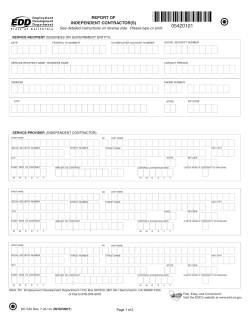

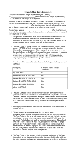

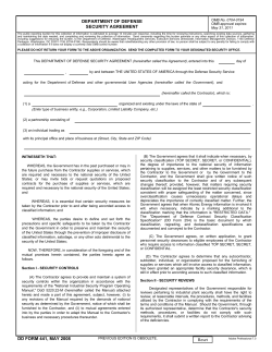


© Copyright 2026