ABC
docz
Explore
Log in
Create new account
Download
Report
No category
Dell UltraSharp U2417HA User`s Guide
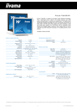
ProLite T1931SR-W1
- telebox hd
TOUGHFLEx™ TyPE SC ENTERTAINMENT CABLE
User Manual Wide LCD Monitor
BDS-SensorBV100-en
PDS-233-4 HDMI Cable Assemblies - How to Order onnectors Product Data Sheet
AV AND AUTOMATION FOR K-12 CLASSROOMS
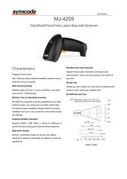
MJ-4209 Handheld/Hand-free Laser Barcode Scanner Characteristics
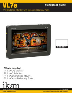
What`s Included QUICKSTART GUIDE 1 x VL7e Monitor 1 x
Multiple Choice Questions Visual Basic 6
© Copyright 2026
About abcdocz
DMCA / GDPR
Report