
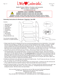
Build your kids the sidewalk classic Put your small fry in the
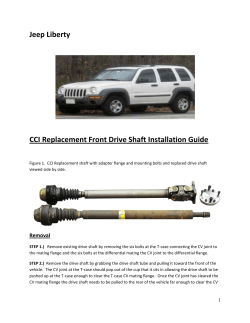
Put your small fry in the
driver's seat of this great little
buggy and watch him grin
Build your kids
the sidewalk classic
Designed
ITS BLACK FABRIC TOP, leather dashboard straps and gas headlamps, this bright red
replica of its prototype—the open roadster of
the early years of this century—will bring a
twinge of nostalgia to grownups and a shriek of
delight from the younger set.
It does a safe, quiet 5 miles per hour, has a
12-volt electrical system driving a 12-volt automobile generator which serves as the motor, and
carries its own built-in battery charger.
It's great for everyday fun on the sidewalk and
by
ROBERT
WOOLSON
sensational in the local Fourth of July parade.
You can buy nearly all of the parts at your
hardware store or at an automotive-parts store.
Assembly is not difficult, particularly if you
follow the pull-apart drawings carefully.
Before you buy or cut any materials, run over
the list of keyed parts and carefully check each
one on the pull-apart drawings. This will give
you a good idea of what goes where on the plywood frame. The dimensions of some of the
parts you have to make, bolt sizes and other im501
FRONT PIECE, BODY
OPENING FOR DRIVE-BELT
ADJUSTMENT (IN ONE PANEL ONLY)
SEAT BACK
TAKE BOLTS HOLDING CENTER TOP BOW
COUNTERSINK
FOR CORNERIRON BOLTS
END PIECE, SEAT, 2 REQD.
502
The steering column is held in position by a
plywood support and metal brace to the
frame. A metal angle serves as the top bearing
portant information are in the keyed list along
with parts nomenclature.
Begin construction with the frame which is cut
from a piece of 1/2-in. plywood. Cut the piece
slightly oversize, about 1/8 in. all around, to allow
for finishing the edges; there must be no splinters.
Then lay out the hole pattern and drill all the
holes which are located by dimension, except
the holes F. Hole diameters are taken directly
from the bolt sizes given in the parts list. The
seven countersunk holes (indicated by concentric
circles) are drilled and countersunk for l.5-in.
No. 8 F.H. wood screws. These hold the brakeshaft supports and the front-fender support, parts
No. 27 and 31. One hole, D, is not countersunk,
as it takes the screw holding the lower end of
the steering-column brace, part No. 59, which
passes through the frame and turns into the
front-fender support.
Holes A and B in the frame must be drilled at
an angle, hole A for the steering post and B for
the brake cable. Drill hole A slightly undersize
and at the approximate angle and then work it
to size and the correct angle later on with a round
I
I
'
DOTTED LINES
INDICATE POSITION OF RUBBER
FLOOR MAT
CHASSIS FRAME, 1/2" PLYWOOD
SHAFT
COLLARS
BRAKE-BAND
TIGHTENER
BRAKE
ASSEMBLY
GROUND-WHEEL DRIVE
file when you fit the steering post. Also you'll
have to do some work with the round file to bring
hole B to the correct angle to take the brake
cable without binding. Holes C, E, G and H are
for the passage of wiring through the frame and
only the approximate location is indicated. The
four holes F take 10-24 F.H. screws (with nuts)
and hold two 3-in. corner irons which serve
as motor-mounting brackets. It's a good idea to
have your motor on hand so that you can determine the distance between the pairs of holes,
as it may vary from that given. Be sure of the
over-all dimensions of the battery case before
you cut the well and make the support.
The front axle consists of a length of hardwood and two steel straps. Note in the pull-apart
BRAKE ECCENTRIC ASSEMBLY
503
KEYED PULL-APART VIEW
(REAR WHEELS, FABRIC TOP,
WIRING AND BATTERY NOT SHOWN)
KEYED LEGENDS
1. WHEEL, SEMI-PNEUMATIC, 12 x 1.75. BALL-BEARING. FOUR REQUIRED (SPARE WHEEL OPTIONAL)
2. SHAFT COLLAR, 1/2 IN.
3. WHEEL SPINDLE, 1/2 x APPROX. 3 IN. STEEL. TH'D.
1/2-13. TWO REQUIRED
4. HEX NUT, 1/2 IN., WITH WASHER
5. HEX NUT, 1/2 IN., TWO REQUIRED
6. HEX NUTS AND LOCK WASHERS, 1/4 IN.
7. FLAT SPACER WASHERS, ONLY TWO SHOWN; FOUR
REQUIRED
8. AXLE STRAPS, TWO REQUIRED
9. AXLE, HARDWOOD
10. SAME AS PART NO. 6
11. SAME AS PART NO. 5
12. HEX-HEAD MACHINE BOLT, 1/4 X 2 1/3"
13. HEX NUT AND WASHER, VA IN., TURNS ONTO END
OF STEERING ROD
14. TIE ROD
15. STEERING ROD
16. SAME AS PART NO. 12. NOTE THAT BOLTS NO. 12
AND 16 PASS THROUGH AXLE ONLY, NOT
THROUGH FRAME
17. KINGBOLT, 1/2 x 2 1/2 IN., TWO REQUIRED
18. PIPE TEE, 1/4-IN. TWO REQUIRED. THREADS
REAMED OUT TO TAKE 1/2-IN. KINGBOLT
19. STEERING ARM, TWO REQUIRED, R. AND L., ONE
HAS THIRD HOLE FOR STEERING ROD
20. LOCK WASHER, 1/2 IN.
21. HEX NUT, 1/2 IN.
22. CHASSIS FRAME, 1/2-IN. PLYWOOD
23. CARRIAGE BOLT, 1/4 X 3 IN. TWO REQUIRED
24. FOOT SWITCH, DPST, PUSH-BUTTON TYPE, NORMALLY OFF
25. ROUND-HEAD 10-24 SCREW, 3/4 IN. LONG. REQUIRES TWO NUTS, LOCK WASHER BETWEEN
NUTS AND TWO SPACER WASHERS
26. BRAKE PEDAL
27. FRONT-FENDER SUPPORT
28. SPOTLIGHT SWITCH, LEVER-ACTUATED, SPDT,
BUT USED AS SPST ONLY
29. SHAFT COLLAR, 1/2-IN., ACTUATES SPOTLIGHT
SWITCH. A SECOND COLLAR IS REQUIRED ON
BRAKE SHAFT TO HOLD IT IN POSITION AFTER
ASSEMBLY
30. WIRE BRAKE CABLE 1/8-IN. DIAMETER, OVERALL
LENGTH APPROX. 28 1/2"
31. BRAKE-SHAFT SUPPORT, OR BEARING. TWO REQUIRED
32. BRAKE SHAFT, 1/2 x 17-IN. STEEL SHAFTING
33. BRAKE ECCENTRIC, 3-IN.-DIA. V-PULLEY
34. BRAKE RETURN SPRING, 6 3/4 IN. LONG, 1-IN.-DIA.
COILS
35. ROUND-HEAD 10-24 SCREW. 2 IN. LONG. LOCKS
END OF BRAKE BAND
36. BRAKE-BAND TIGHTENER, 2-IN. V-PULLEY
37. BRAKE BAND, 1/2-IN. V-BELT, OVERALL LENGTH
APPROX. 16 1/2"
38. BRAKE-BAND LUG, 1/8 x 1 x 6-IN. STEEL OUTER
END GIVEN ONE-QUARTER TWIST
39. SHAFT COLLAR, 1/2-IN.
40. BRAKE STUD, 5/16-.|N. STEEL, TWO REQUIRED.
THREAD 5/16-18 AND FIT EACH WITH TWO HEX NUTS
41. REAR AXLE, 1/2 x 23 1/4-IN. LENGTH OF DRILL ROD
42. BRAKE DRUM, 4-IN. V-PULLEY. DRILL 5/16-IN. HOLES
THROUGH WEB ON 2 1/8-IN. CENTERS FOR BRAKE
STUDS
43. BALL-BEARING PILLOW BLOCK FOR 1/2-IN. SHAFT.
TWO REQUIRED
44. MACHINE BOLT, 1/4 X 1 IN. WITH NUT AND LOCK
WASHER. TWO REQUIRED. THESE BOLTS JOIN
MOTOR MOUNTING LUGS TO 3-IN. CORNER IRONS,
ONE LEG OF EACH IRON BEING CUT TO 2 1/8 IN.
LENGTH. DRILL HOLES FOR BOLTS CENTERING 15/8
IN. ABOVE THE CORNER-IRON BEND
45. DPDT TOGGLE SWITCH. SEE WIRING DIAGRAM
46. BATTERY WELL AND SUPPORT
47. CORNER IRON, TWO REQUIRED TO SUPPORT
DASHBOARD **
48.
49.
50.
51.
HEAD LAMP BRACKET
HEAD LAMP, DRY-CELL POWERED, TWO REQUIRED
PEDAL. ACTUATES START-STOP SWITCH
FRONT FENDER, TWO REQUIRED. EACH CUT FROM
3/8-IN. PLYWOOD, 4 IN. WIDE, 12 IN. LONG WITH
UPPER CORNERS ROUNDED TO 1-IN. RADIUS,
LOWER OUTSIDE CORNER TO 2-IN. RADIUS
52. DASHBOARD, 3/4-|N. PLYWOOD
53. SOFT-IRON RIVETS, 1/8 x 3/4 IN. EXACT LENGTH
DEPENDS ON WIDTH OF SHAFT COLLAR USED
54. STEERING CRANK
55. SHAFT COLLAR, 1/2 IN. NOTE THAT PARTS NO. 54
AND 55 ARE JOINED WITH RIVETS, PART NO. 53
56. NO. 8 WOOD SCREW 1 1/2- IN. LONG
57. STEERING COLUMN, 1/2 IN. DIA., 18 IN. LONG,
STEEL SHAFTING
58. STEERING-COLUMN SUPPORT, 3/4-|N. PLYWOOD
59. STEERING-COLUMN BRACE
60. SCREWEYE, 1/2 IN. TWO REQUIRED. TAKES SWIVEL
SNAP ON TOP STRAP
61. FRONT PIECE, BODY
62. SHEET-METAL SCREW, SIZE 1/2—8 (OR 10), BINDER
HEAD, FIVE REQUIRED
63. CORNER IRON, 1 IN., FIVE REQUIRED TO ATTACH
BODY TO FRAME. EIGHT REQUIRED FOR JOINING
THE FOUR PARTS OF BODY
64. DRIVING AND DRIVEN V-PULLEYS, DRIVING PULLEY,
2 IN. DIA., 5/8-IN. BORE. DRIVEN PULLEY, 10 IN.
DIA., 1/2-BORE. USE 1/2-IN, V-BELT, 34 IN. LONG
65. TURNBUCKLE, SIZE (CLOSED) 5 1/4 N HOLDS MOTOR IN FIXED POSITION
66. AUTO GENERATOR, 12-VOLT. SERVES AS MOTOR
WITHOUT ANY ALTERATION
67. CARRIAGE BOLTS, VA X V/Z IN. FOUR REQUIRED
WITH HEX NUTS AND WASHERS
68. CHARGER, 12-VOLT
69. TURNBUCKLE, PART NO. 65, IS FITTED WITH NUTS
AND LOCK WASHERS TO PREVENT IT FROM LOOSENING
70. BACK PIECE, BODY, 3/8x 6 5/16 x 15 3/16-IN. PLYWOOD
71. SIDE PIECE, BODY. TWO REQUIRED. ONLY OWE
HAS OPENING FOR BELT ADJUSTMENT
72. BUTT HINGE, 1 1/2-IN., TWO REQUIRED
73. BEARING, TOP END OF STEERING COLUMN
74. SCREW, 10-24, 1 IN. LONG
75. CORNER IRONS, 1-IN. AND 3-IN. SIZES, TWO REQUIRED OF EACH
76. REAR FENDER, 3/8 x 4 x 12-IN. PLYWOOD WITH
THREE CORNERS ROUNDED TO 1-IN. RADIUS
77. RUBBER HOSE, 5/8-IN. O.D.
78. STEERING WHEEL, 1/2-IN. BORE, 10 1/4-IN., DIA.,
CAST-IRON V-PULLEY
79. SHAFT COLLAR, 1/2-IN.
80. ELECTRICIAN'S BLACK PLASTIC TAPE
81. SIDE OF SEAT, TWO REQUIRED
82. SEAT BOTTOM, 3/8.|N. PLYWOOD. MEASURES 8 1/4IN. WIDE, 21 7/8-IN. ON LONG SIDE, 20 IN. ON SHORT
SIDE. PADDED WITH CORRUGATED-RUBBER STAIR
TREAD
83. SEAT BACK
84. MOTOR-COMPARTMENT COVER, OR DECK. 3/8 x
8 3/4 x 16-IN. PLYWOOD
85. DECK HANDLE
86. LEATHER STRAP, TWO REQUIRED WITH BUCKLES
87. STOPLIGHT, 12-VOLT
88. HOOK AND EYE, 31/2 IN., HOLDS HINGED SEAT IN
DOWN POSITION. EYE SCREWS INTO BACK OF
SEAT NEAR BOTTOM. HOOK SCREWS INTO FRAME
* PURCHASE A 24-IN. LENGTH OF DRILL ROD AND CUT
TO REQUIRED LENGTH AFTER MAKING TRIAL ASSEMBLY. LENGTH MAY VARY FROM THAT GIVEN
DUE TO POSSIBLE VARIATIONS IN WIDTH THROUGH
PILLOW-BLOCK BEARINGS AND WHEEL HUBS
** INSIDE CORNER IRONS ARE USED THROUGHOUT
ASSEMBLY. ALL 1-IN. IRONS JOINING BODY PARTS
ARE HELD WITH 10-24 SCREWS AND SQUARE NUTS
505
Battery-powered headlights snap onto metal brackets
attached to the dashboard. The brackets come
with the lamps. Note also the construction of the
front axle and the steering-knuckle assembly
506
The brake band is a 1/2-in. V-belt anchored to a stationary lug and a tightener, and
passes around a V-pulley on the axle. Note the two studs which engage the wheel
view that there are three pairs of bolts that pass
through the axle, the two kingbolts, the pair of
carriage bolts holding the frame to the axle,
and a pair of machine bolts that hold the three
parts of the axle together. The wheel spindles
swing on the kingbolts, which pivot 1/4-in. pipe
tees. Threads in the body of the latter are reamed
out to take the kingbolts in a close fit. A hex nut,
lock washer and a steering arm are placed on
each spindle before turning the latter into the
threaded stem of each tee. You'll see the order
of assembly in the pull-apart view. A shaft collar
with setscrews holds each wheel.
Assemble the rear axle in its bearings on the
frame. Then make the brake-shaft supports and
screw them in place on the underside of the
frame, noting that the one that is grooved for
the brake-band lug goes on the right side of the
frame, viewed from the front. The complete
brake assembly is shown pulled apart. There
are two points to note especially in this assembly.
First, the brake-band lug, part No. 38, drops
into the groove in the brake-shaft support. The
wood screw holding it in the groove passes
through the frame from the top. side, through
the lug and is turned into the brake-shaft support. The inner end of the lug is held by a 10-24
screw (with nut) which passes through a hole in
the frame. This hole must be drilled through the
frame after the parts are located. Second, the
screw holding the forward end of the brake
band in the groove in the brake-band tightener,
part No. 36, passes through the band and a hole
in the tightener and shaft.
Parts of the brake-eccentric assembly are
shown on page 503. A 5/16 x 1 3/8-in. stud is crossdrilled near the unthreaded end to take the end
of the brake cable. A nut and washer are run
down on the stud and the cross-drilled end inserted in a hole drilled through one side of the
pulley (eccentric) rim. The free end of the
cable is passed through the hole near the end
of the stud and the nut tightened, clamping
the end of the cable securely in place. This arrangement provides adjustment of the brakecable length when the assembly is complete. The
return spring is attached to the stud with a second nut and washer and the opposite end of
the spring attaches to an anchor on the bottom
of the frame.
Note now the similarity between the groundwheel drive, and the brake assembly. Both make
use of short studs, the unthreaded ends of which
enter holes drilled through the inner half of the
wheel webs. Two studs are required for the brake
but only one for the drive.
The steering gear is of simple construction
and consists of the tie rod, steering-rod, crank,
507
Swivel snaps riveted to the ends of straps hook into screweyes in the top edge of the dash
the column, column support, brace and wheel.
The latter is a 10.25-in.-diameter V-pulley, the
V-groove being filled with a 5/8-in.-diameter rubber hose and then wrapped with electrician's
plastic tape. This makes a neat, realistic wheel
rim. When assembling the steering gear you may
need to make some adjustment in the "geometry" by bending the arms so that the front
wheels toe correctly.
The body also is of the simplest construction,
made entirely of 3/8-in. plywood and joined with
1-in. corner irons, each held in place with two
10-24 screws and square nuts. Parts for the
seat are assembled in the same manner, using the
same size irons and screws. The one exception
508
in this procedure is the method of joining one
leg of each corner iron holding the body to the
frame. Here a No. 8 or 10 sheet-metal screw 1/2
in. long (part No. 62) is used instead of a
10-24 screw and nut to join the leg of the iron
to the frame. Dimensions of the seat bottom,
fenders and hinged rear deck, or cover, will be
found in the parts list. Rear fenders are joined
to the body with corner irons (parts No. 75)
and 10-24 screws and nuts. Front fenders are
attached to dashboard and fender support with
1.5-in. No. 8 screws.
Next step is to add the top and install the
wiring. The top, authentic in appearance, consists of a metal frame covered with an artificial-
Assemble the top before placing it on the car. The metal
frame, consisting of front, back and center bows, and
braces, is made from aluminum rod and tubing that is available in all hardware, building supply, and hobby stores
CHARGER WIRING SCHEMATIC
X
BRAKE-LIGHT
TERMINAL
N O T USED
SWITCH
ACCELERATOR
SWITCH
12-V. BATTERY
CHARGE
OFF
GO
SWITCH
GEN.
110-V. A.C.
110-V.+ 12-V. BATTERY
CHARGER
COMPLETE ELECTRICAL WIRING SCHEMATIC FOR SIDEWALK CLASSIC
CENTER-OFF TOGGLE SWITCH
110-V. A.C.
STANDARD SURFACEMOUNTED UTILITY BOX
CHARGE
GO
OFF
CHARGE-OFF-GO
SWITCH. D.P.D.T.
(BOTTOM VIEW)
BRAKE-LIGHT
SWITCH S.P.S.T.-N.O.
AUTO
GENERATOR
# 16 WIRE
# 10
ACCELERATOR
SWITCH D.P.S.T.
N.O. PUSH
BUTTON
# 10
# 16
WIRE
12-V. STORAGE
BATTERY
# 16
# 16
# 10 WIRE
12-V. 30-AMP.
CHARGER
X
510
- +
12-V
DC.
OUT
110-V.
DC.
IN
SWITCH TERMINAL NOT USED
STOP
LIGHT
Ready access to all electrical equipment—battery, motor, switch and charger—is made possible by the hinged seat, top and deck, which tilt forward. The seat is held down with a hook
leather fabric, the pattern for which is given on
page 509. Overall measurements before hemming are shown with the exception of one dimension, from the rear window opening to the
bottom of the back flap, which is given after
hemming.
Don't cut the fabric until after you have made
and assembled the bows and braces. You can
bend the center bow by hand, but you run the
risk of getting an uneven bend and spoiling the
contour of the roof as a result. Instead, borrow
an electrician's conduit bender for this job.
After bending, flatten at the points indicated and
drill holes for the bolts. Then bend the front and
back bows, flatten the ends slightly, and also
drill the holes for the bolts.
The holes in the front bow for the bolts that
hold the upper end of the braces are located
and drilled after a trial assembly.
Now refer to the drawing on page 509 for
the location of the holes for the bolts holding
the center bow to the ends of the seat. Drill these
holes and mount the assembled bows temporarily
so that you can more easily fit the fabric top.
Lay the fabric over the bows and determine the
location of the pleats, or tucks, and the amount
to be turned under for the hems. This done, sew
The electricals are housed in the body, with the battery in a well under the seat. Note the position of the
charger and the "off-go-charge" switch. Note also the
use of snap-on terminal clamps on the battery
511
The back drop, or flap, of the fabric top is attached
to the back of the seat with storm-sash hangers. The
rear window is fitted with a sheet of clear plastic
the hems all around, making the pleats as you
go. Cut the opening for the rear window. Cut
thin, clear plastic about 1/2 in. larger all around
than the opening and sew in place. After pleating and hemming, fold the forward end of the
fabric around the front bow and fasten with
split rivets. Note that the leather straps are attached to the top with split rivets at the pleats
and at the front edge of the fabric. Attach a
The wiring from the foot-operated switch and the
stoplight switch is stapled to the underside of the
frame. Wire sizes are indicated on the schematic
swivel snap to the free end of each strap, fastening with split rivets.
The back drop, or flap, of the top attaches
to the back of the seat with three storm-sash
hangers. Note that the sash half of the hanger
is riveted to the lower edge of the fabric, while
the other half of each hanger is attached to the
back of the seat with 10-24 screws and hex nuts.
Note that when everything is assembled the
hinged seat, deck and top tip forward to give
access to the electricals, motor, battery, charger
and the off-run-charge switch. The exact location of the switch and charger is of no importance; place them so there is access to each.
When wiring, follow the wiring diagram which
gives the wire sizes to use. Wires from the startstop, foot-controlled switch and to the stoplight
switch are stapled to the underside of the frame.
Before making the test run, be sure you have
the correct tension on the driving V-belt and that
all nuts and screws have been properly tightened.
The fifth, or spare, wheel pictured is optional.
The carrier is simply a threaded 1/2-in. stud and
shaft collar installed on the back body panel.
Brackets for the headlights (the brackets come
with the units) are screwed to the dashboard as
shown.
colors are optional
Paint colors are optional. The original pictured was painted a bright red with a silver
striping, an attractive combination. The top of
the plywood frame was finished in natural color.
The disk wheels were sprayed with silver paint.
There are some interesting decorative touches
that you can add which will increase the authentic look and at the same time make the car more
fun to own. For example, if you shop around,
you should b.e able to find one of those old
rubber-bulb operated auto horns. If you can
find one with a shiny brass bell, so much the
better.
The same material you used to make the top
would serve very well as a covering fabric if
you chose to upholster the seats. You wouldn't
have to be fancy. Just cover the wooden seat and
back with 1 or 1.5-in. of foam rubber, cover with
the fabric, then tack to the edges of the seat. Use
large-headed colored upholstery nails. For a
final touch of authenticity, drive some of these
nails into the back and the seat in a grid pattern, with about 6 in. between nails, to imitate
the old upholstery buttons.
See also: bicycles; cars, midget; stage coach; train,
children's; unicycle.
512


© Copyright 2026