
Document
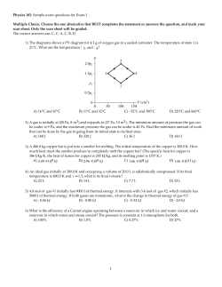
Home Search Collections Journals About Contact us My IOPscience Thermal analysis of the building envelope of lightweight temporary housing This content has been downloaded from IOPscience. Please scroll down to see the full text. 2014 J. Phys.: Conf. Ser. 547 012011 (http://iopscience.iop.org/1742-6596/547/1/012011) View the table of contents for this issue, or go to the journal homepage for more Download details: IP Address: 176.9.124.142 This content was downloaded on 04/12/2014 at 12:47 Please note that terms and conditions apply. 32nd UIT (Italian Union of Thermo-fluid-dynamics) Heat Transfer Conference IOP Publishing Journal of Physics: Conference Series 547 (2014) 012011 doi:10.1088/1742-6596/547/1/012011 Thermal analysis of the building envelope of lightweight temporary housing Fabio Fantozzi, Pietro Galbiati, Francesco Leccese, Giacomo Salvadori, Michele Rocca Dept. of Energy Engineering, Systems, Territory and Constructions University of Pisa, School of Engineering, Largo Lucio Lazzarino, Pisa, IT. E-mail: [email protected] Abstract. In the last few years, to meet the need of build efficient homes in a short time and with maximum constructive simplification, lightweight prefabricated building systems have proved to be particularly suitable, especially in geographical areas which must deal with emergency situations (i.e., temporary housing). In this paper the winter and summer thermal performance of a building prototype, realised with modular steel framed elements, have been studied, in both winter and summer conditions. Special attention has been paid to the optimisation of the dynamic thermal performance of the multi-layered envelope structures. The dynamic thermal behaviour of the outer wall, analysed and discussed in details in the paper, shows that it is possible to improve the performance of lightweight walls by using an optimised stratigraphy characterised by an opportune sequence of resistive and capacitive layers. The influence of inner structures (partitions, floor and roof) on the building thermal behaviour has also analyzed trough the introduction of room performance indices appropriately defined. The results of the study have been discussed with special reference to the requirements fixed by the Energy Performance Buildings European Directive (EPBDs) and the resulting implementation in Italian Legislation. 1. Introduction In the last few years, lightweight prefabricated building systems have proved to be particularly suitable in geographical areas which must deal with emergency situations such as earthquakes, weather-climate events, situations of conflict, and others (see Figure 1). In the past a considerable part of post-disaster temporary housing programs have been unsustainable and culturally inadequate as a result of unsuccessful strategies, misunderstandings about users’ real needs and misconceptions in dealing with local conditions and resources [1]. Disaster-affected families who have lost their homes need a private and secure place to restart their daily activities as soon as possible after the disaster, yet temporary housing programmes tend to be overly expensive, too late and responsible for undesirable impacts on the urban environment [2]. Housing reconstruction programmes play a decisive role on the disaster recovery and providing temporary housing is a crucial step of these programmes. During the reconstruction of permanent housing, it allows victims to have a private and secure place to return to their normal life. It has been widely used after the largest scale disasters but it has also been greatly criticized, mainly for being unsustainable and culturally inadequate [1]. The selection of temporary housing to ensure sufficient levels of comfort is very important also for the psychological effects on the earthquake survivor. A research on a comparison of people assigned to Content from this work may be used under the terms of the Creative Commons Attribution 3.0 licence. Any further distribution of this work must maintain attribution to the author(s) and the title of the work, journal citation and DOI. Published under licence by IOP Publishing Ltd 1 32nd UIT (Italian Union of Thermo-fluid-dynamics) Heat Transfer Conference IOP Publishing Journal of Physics: Conference Series 547 (2014) 012011 doi:10.1088/1742-6596/547/1/012011 containers, converted into mobile homes, vs. wooden dachas vs. a control group, that had not lost their homes in the earthquake, have shown that container inhabitants reported greater discomfort, felt more dominated by the situation and, importantly, reported more psychological stress symptoms than those living in dachas or in regular homes. Again, it may surprise that the well-being of people living in dachas was closer to that of control participants than to fellow earthquake victims living in containers. In particular, people in dachas did not reliably differ from control participants in terms of feeling dominated or in terms of psychological stress symptoms, but they did express greater general discomfort [3]. Figure 1. Examples of temporary housing units in earthquake areas: (left) L'Aquila, 2009; Haiti, 2010; Japan, 2012 (right). It may be stated that these buildings require shorter construction times and simple construction steps, and they should not be mistakenly considered as "temporary housing." On the contrary, they must ensure high safety standards (against fires, earthquakes, etc.) as well as high levels of living comfort (thermal, acoustic, etc.), even in remote areas lacking services and utilities, such as electricity or gas supply. This study is focused on the analysis of the dynamic thermal behaviour of a new prefabricated building system; the EN ISO 13786 method has been followed, implementing a spreadsheet calculation file [4]. In particular, the parameters: periodic thermal transmittance Yie (Wm-2K-1), decrement factor fa and time shift φ (h) have been analyzed. The aim of the research was to study the dynamic thermal characteristics of the building envelope in order to enhance its performance by optimizing the stratigraphy of the outer multi-layered walls. The choice of the stratigraphy which optimizes the dynamic thermal characteristics has been performed using the method of lumped parameters [5]. It also aims to explain that the inner structures (partitions, floor and roof) play a role in the summer thermal performance considering the passive behaviour of the building. The analysis of the influence of inner structures on the energy performance of the room was established through the introduction of performance indices, similar to those above, but appropriately redefined [6]. 2. Description of the new building system The study has been carried out (with both computational simulations and on-site measurements) on a building prototype [6]. The new building system consists of modular steel framed elements (preassembled at the factory), which are shipped to the construction site including fixtures and equipment (see Figure 2). The main features that characterize the new building system can be summarized in the following aspects: shorter construction times, construction flexibility, good seismic performance, energy saving, acoustic insulation, workplace safety, installation without scaffolding, easy maintenance and low costs. 2 32nd UIT (Italian Union of Thermo-fluid-dynamics) Heat Transfer Conference IOP Publishing Journal of Physics: Conference Series 547 (2014) 012011 doi:10.1088/1742-6596/547/1/012011 The system involves the construction of a foundation slab designed according to the building loads and to the ground properties, taking into account of seismic aspects. The outer wall are anchored on the edge of the foundation. The modular elements of walls and floors (which constitute the supporting structure) are joint whit bolts. The new building system allows to create different solutions of ventilated facade covering whit stone, ceramic, aluminium, plastic materials with various surface finishes. The building typologies that the systems includes are multi-storey residential buildings, emergency housing units, commercial/office and industrial building. Figure 2. Images of the new lightweight prefabricated building system (courtesy of HOMLEG, www.homleg.it). In Table 1 are shown the stratigraphies of the outer walls, horizontal structures (floor) and inner partitions used in the standard solution [6], currently under production in Italy (Tuscany Region). In particular in Table 1, for each layers, are shown: thickness (d), thermal conductivity (λ), density (ρ) and thermal capacity (c). 3. Winter and summer thermal performance of the building envelope The evaluation of the winter and summer thermal performance was initially carried out on the outer wall (W0) without the external coating layer (Ref.: Outer wall, layers 1 and 2, Table 1). The winter behaviour of the outer wall has been evaluated by calculating the overall thermal tramittance U, amounting to 0.29 Wm-2K-1 (RTot=1/U=3.45 m2KW-1). In Italy, as European Directive EPBD implementation [7-9], limit values (Ulim) of the overall thermal transmittance for the outer wall of buildings have been fixed for each of the six climates zone (A÷F) in which the Italian territory is slip up. In particular, the more stringent limit values (Italian colder climate, zone F) are: Ulim=0.33 Wm-2K-1 (for vertical walls). It can be observed that the overall thermal trasmittance of the W0 wall is always less than the limit values set for each climate zone [7]. As regards the summer thermal behaviour, has been calculated the periodic thermal transmittance Yie (Wm-2K-1), the decrement factor fa. and the time shift φ (h). In Italy, for the municipalities in which the maximum intensity of the solar radiation on a horizontal plane is higher than 290 Wm-2, the following requisite have been imposed [8]: for the vertical opaque walls (facing South, South-West and South East), the value of the surface mass Ms should be higher than (Ms)lim=230 kgm-2, otherwise the value of the periodic thermal trasmittance Yie should be lower than (Yie)lim=0.12 Wm-2K-1. On the national guidelines for energy certification of buildings [9], in order to rate the "summer performance level" of the opaque outer walls the following parameters are used: decrement factor fa and time shift φ (see Table 2). In [9] it is also specified that, in cases of values of fa and φ do not belong to the same performance level, the assignation of the building summer performance level is based on the value of the time shift. The W0 wall exhibits: Yie=0.121 Wm-2K-1, fa=0.41 and φ=6h49' (see Table 3). The W0 wall does not fulfil the limits imposed on the summer thermal behaviour and results in performance level IV (see Table 2). 3 32nd UIT (Italian Union of Thermo-fluid-dynamics) Heat Transfer Conference IOP Publishing Journal of Physics: Conference Series 547 (2014) 012011 doi:10.1088/1742-6596/547/1/012011 In order to achieve better summer performance, it was decided to gradually fill (in step of 1cm) the air cavity (Ref.: Outer wall, layer 5, Table 1) with insulating material (i.e. rock wool). Consequently 15 different wall stratigraphies (from W1 to W15, see Table 3) has been examined. In Table 3 the calculation results, for W0 (outer wall in the standard solution) and for the subsequent 15 stratigraphies (from W1 to W15), are shown. All the dynamic thermal characteristics has been calculated with respect to a reference period (24h) of the oscillation of the thermal field. It can be observed that it is sufficient the addition of a centimeter of insulating material to fulfil the limit imposed on periodic thermal trasmittance, however the W1 wall remain in performance level IV (φ=7h23', W1, see Table 3). Partition Floor Outer wall Table 1. Stratigraphy of the main components of the new lightweight prefabricated building. d (cm) λ (Wm-1K-1) ρ (kgm-3) c (JK-1kg-1) Ext 1- Outer coating 2- Air cavity 3- Expanded polystyrene 4- OSB panels 5- Air cavity 6- OSB panels 7- Plasterboard sheet Int 4.5 8 1.8 15 5.4 1.2 0 0.033 0.13 0 0.13 0.21 1 20 650 1 650 900 1004 1450 1700 1004 1700 837 Top 1- Tile, cork 2- Silicone-mastic 3- Plywood 4- Neoprene 5- Plywood 6- Steel 7- Air cavity 8- Plywood Down 0.8 0.5 3 0.3 3 0.5 19.5 1.4 0.045 0.13 0.13 52 0 0.13 130 500 500 7800 1 500 1764 2092 2092 460 1004 2092 1- Plasterboard sheet 2- Rock wool 3- Plasterboard sheet 1.3 8 1.3 0.21 0.041 0.21 900 70 900 2300 1030 2300 Table 2. "Summer performance level" for the opaque building envelope. Level Description Time Shift φ (h) Decrement Factor fa (-) I Excellent II Good III Medium IV Sufficient V Poor φ > 12 10 < φ ≤ 12 8 < φ ≤ 10 6<φ≤8 φ≤6 fa < 0.15 0.15 ≤ fa < 0.3 0.3 ≤ fa < 0.4 0.4 ≤ fa < 0.6 fa ≥ 0.6 From Table 3 it can be observed that 3 cm of insulating material are necessary to achieve the performance level III (φ = 8h21', W3) and 9 cm of insulating material are necessary to achieve the performance level II (φ =10h10', W9). The most insulated solution (W15) exhibits the following thermal properties (see Table 3): U=0.146 Wm-2K-1 (RTot=1/U=6.85 m2KW-1), Yie=0.026 Wm-2K-1, 4 32nd UIT (Italian Union of Thermo-fluid-dynamics) Heat Transfer Conference IOP Publishing Journal of Physics: Conference Series 547 (2014) 012011 doi:10.1088/1742-6596/547/1/012011 fa=0.175 and φ=11h38'. Despite of the excellent thermal behaviour, U<<Ulim, Yie<<(Yie)lim, the W15 wall achieves a summer performance level rated as good (level II), being: 10<φ≤12h. To further improve the dynamic thermal behaviour of the outer walls the Authors have proceeded with an optimization of the stratigraphy of the W15 wall [10-12]. Table 3. Thermal characteristics of the 16 stratigraphies analyzed: thermal trasmittance U, periodic thermal trasmittance Yie, time shift φ and decrement factor fa. Thickness insulating U (Wm-2K-1) Yie (Wm-2K-1) φ fa Stratigraphy material (cm) 0 0.295 0.121 6h49' 0.410 W0 1 0.276 0.111 7h23' 0.403 W1 2 0.258 0.095 7h55' 0.370 W2 3 0.243 0.083 8h21' 0.340 W3 4 0.229 0.072 8h43' 0.314 W4 5 0.217 0.063 9h03' 0.292 W5 6 0.206 0.056 9h21' 0.273 W6 7 0.196 0.050 9h38' 0.256 W7 8 0.187 0.045 9h54' 0.242 W8 9 0.179 0.041 10h10' 0.228 W9 10 0.172 0.037 10h26' 0.217 W10 11 0.165 0.034 10h42' 0.207 W11 12 0.158 0.031 10h58' 0.197 W12 13 0.153 0.029 11h14' 0.188 W13 14 0.147 0.026 11h29' 0.180 W14 15 0.146 0.026 11h38' 0.175 W15 4. Optimization of outer multi-layered walls The problem of how to define the stratigraphic pattern of a wall provided with a thermal resistance RTot (including surface thermal resistances) and a thermal capacity CTot fitting for minimizing the periodic thermal transmittance Yie (i.e. the decrement factor fa) has been solved by using the method of lumped parameters [10-12]. This method will be solved by considering that the definition “wall stratigraphy” refers to how many purely resistive layers provided with a thermal resistance rs and how many purely capacitive layers provided with a thermal capacity cs constitute that specific wall on the basis of a given layer sequence order. A 2n+1 layered wall, consisting of n capacitive layers and n+1 resistive layers, can be outlined as follows (with R=Σrs and C=Σcs): [INT] [rn] [cn] [rn-1].......[r1] [c1] [r0] [EXT] Given that the different resistive and capacitive layers are respectively represented by triangular matrices of the following type ( j = − 1 and ω angular frequency of oscillation of external field): 1 rs 0 1 , 0 1 j ω cs 1 For n=∞, we obtain a typical homogeneous wall (i.e. a wall with uniformly distributed capacity C and thermal resistance R). The problem of defining the wall stratigraphic pattern fitting for minimizing Yie is characterised by the following non-dimensional parameter: 5 32nd UIT (Italian Union of Thermo-fluid-dynamics) Heat Transfer Conference IOP Publishing Journal of Physics: Conference Series 547 (2014) 012011 doi:10.1088/1742-6596/547/1/012011 γ = ω RC which corresponds to the product of an outer thermal field angular frequency ω and the wall’s time constant RC. The obtained results can be summarized as follows. For γ<18, the optimal symmetry configuration is that obtained with n=1, corresponding to a threelayered wall, whose capacitive layer (C) is placed between two identical resistive layers (R/2), of the following type: [INT] [R/2] [c] [R/2] [EXT] ( T1 ) Such a configuration is characterized by: Yie = 1 / R 1 + γ 2 / 16 , ϕ = ( P / 2π ) arctan(γ / 4 ) For 18<γ<42, the optimal symmetry structure is that obtained with n=2 (five-layered wall), of the following type: [INT] [r0] [c1] [r1] [c1] [r0] [EXT] (T2) For 42<γ<76 the optimal solution is a T3 symmetry structure obtained with n=3 (seven-layered wall), for 76<γ<100 the optimal solution is a T4 symmetry structure obtained with n=4 (nine-layered wall), and so on. For each case with n>1, the optimal resistance and capacity values corresponding to the different layers are dependent on the γ value. It has been proved that entirely symmetric walls Tn , consisting of n capacities and n+1 resistances whose values are all identical, with cn =C/n and rn=R/(n+1), approximate with a very good accuracy the behaviour of the above defined optimal configurations Tn , within the respective γ intervals. It must be observed that whatever real wall can be outlined as a lumped-parameter wall provided with a sufficiently high number of layers. The above presented analysis shows that, for a given γ, the optimal stratigraphy is characterized by a low n value, which excludes the possibility of it being other than a lumped-parameter stratigraphy. The lumped parameter model is therefore not limitative. Even the problem of defining the wall stratigraphic pattern fitting for maximizing the time shift ϕ is characterized by a non-dimensional parameter γ; the solution to this problem is very similar to the solution previously obtained with regard to minimizing Yie, if we except that the transition from one optimal stratigraphic pattern to another takes place for considerably lower γ values. The analysis turns out to be very simple when its spectrum is limited to entirely symmetric type Tn walls. If such is the case: for γ<3.5, a type T1 wall gives an advantageous solution, with n=1 (three-layered wall), for 3.5< γ<6.7, a type T2 wall gives an advantageous solution, with n=2 (five-layered wall), for 6.7< γ< 10.1, a type T3 wall gives an advantageous solution, with n=3 (seven-layered wall) and so on. In the case of high γ values, the number of layers which are needed to maximize the time shift ϕ is found to be in its turn very high, whereas the relevant structure approximates a homogeneous wall’s structure, with an uniform distribution of R (including surface thermal resistances) and C. 5.Stratigraphic pattern optimization of the outer wall In this analysis has been performed for the W15 wall without the innermost coating layer (Ref.: Outer wall, layer 7, Table 1), hereinafter named W15* (see Table 5). In Table 4, the thermal properties of the W15* wall, in particular the thermal resistance R (m2KW-1), the thermal capacity C (Jkg-1K-1) and the thermal diffusivity α (m2μs-1) of the different layers, have been reported. In Table 4 the parameters p1 and p2 have been also reported. The parameters p1 and p2 are defined as: p1=C/CTot, p2 =R/RTot, where 6 32nd UIT (Italian Union of Thermo-fluid-dynamics) Heat Transfer Conference IOP Publishing Journal of Physics: Conference Series 547 (2014) 012011 doi:10.1088/1742-6596/547/1/012011 CTot (kJm-2K-1) is the overall thermal capacity of the wall and RTot (m2KW-1) is the overall thermal resistance of the wall. In the analysed case (W15*) CTot and RTot are respectively: 92.7 kJm-2K-1 and 6.81 m2KW-1. Table 4. Thermal properties of the W15* wall (see also Table 1). EXT 2 -1 R m KW -2 -1 C kJm K 2 -1 α m μs p1 p2 0.04 Expanded polystyrene 2.424 2.3 1.14 0.025 0.365 OSB panel Insulating material OSB panel INT 0.415 59.7 0.12 0.644 0.063 0.13 (Table 3, W15) 0.138 19.9 0.12 0.215 0.021 3.659 10.8 0.57 0.117 0.551 In order to understand the behaviour of the resistive layers (for example, a layer of insulating material), the value assumed by p1 must be sufficiently low; similarly the capacitive layers should be evaluated considering the value assumed by p2 [13-14]. In view of these aspects a new stratigraphy (Type 1) has been analysed. The Type 1 wall, keeping the same alternation of materials capacitive-resistive-capacitive-resistive of W15* and the same thicknesses of the different layers, is composed only of OSB panel (capacitive layers) and expanded polystyrene (resistive layers). The optimization of the dynamic thermal behaviour of the Type 1 is then processed by changing the sequence of layers from the inside outwards, see Figure 3. Starting from the Type 1, three other stratigraphy have been designed in order to show the variation of the dynamic thermal characteristics of the opaque envelope of the new building system examined (see Figure 3 and Table 5). The Type 2 has been obtained without vary the thicknesses of the individual layers and by shifting toward the centre the capacitive layers (OSB panel) and outwards the resistive layers (expanded polystyrene). The Type 3 has been obtained by keeping the order of the layers of the Type 2 but making it symmetrical (the two layers of expanded polystyrene have the same thickness equal to 11.5 cm). The Type 4 has been obtained by searching the configuration that minimize the periodic thermal transmittance Yie through the use of the method of lumped parameters applied to the Type 3. The results of the optimization is a seven layers stratigraphy with alternated resistive and capacitive layers that shown the following thermal properties: ω=7.27·10-5, γ =48.24 (42<γ<76), CTot= 86.23 kJm-2K-1 and RTot=7.69 m2KW-1. The resistive layers (expanded polystyrene) are 4 of thickness 5.8 cm and the capacitive layers (OSB panel) are 3 of thickness 2.4 cm. A further fractionation of the stratigraphy does not allow appreciable improvements of the dynamic thermal performance of the wall. Figure 3. Different type of walls studied (A: OSB Panels, B: insulating material, C: expanded polystyrene). 7 32nd UIT (Italian Union of Thermo-fluid-dynamics) Heat Transfer Conference IOP Publishing Journal of Physics: Conference Series 547 (2014) 012011 doi:10.1088/1742-6596/547/1/012011 From the results shown in Table 5, it can be observed that the different analysed solutions obviously have the same overall thickness (30.2 cm) and a surface mass Ms (kgm-2) very low (always less than 60 kgm-2). Of course the Type 1, 2, 3 and 4 walls, that are designed with the same materials and the same overall thickness, have the same thermal transmittance (U=0.130 Wm-2K-1) that is considerably lower than the limit value fixed for the climate zone more burdensome by the Italy legislation. From the results reported in Table 5, it can be also observed that the Type 4 wall, optimized with the method of lumped parameters, shows a significant improvement of the time shift with respect to all the other proposed solutions. In particular the Type 4 wall, with φ=13h55', is characterised by a summer thermal performance level rated as excellent (level I). Table 5. Thermal characteristics of W15* wall and the new Type 1..4 walls. d W15* Type 1 Type 2 Type 3 Type 4 Ms -2 U -2 RTot -1 2 CTot -1 -2 Yie -1 -2 fa φ 0.20 0.22 0.09 0.08 0.05 11h02' 10h07' 8h51' 8h47' 13h55' -1 (cm) (kgm ) (Wm K ) (m KW ) (kJm K ) (Wm K ) 30.2 30.2 30.2 30.2 30.2 59 51 51 51 51 0.147 0.130 0.130 0.130 0.130 6.81 7.69 7.69 7.69 7.69 92.69 86.23 86.23 86.23 86.23 0.029 0.028 0.012 0.011 0.006 6. Thermal influence of the inner structures The thermal comfort of a building depends not only on the outer structures (roof and façades) but also on the inner structures, this is especially evident when the passive behaviour of the building is studied, that is when the response of the building to variations of the external temperature is analysed in the absence of an air conditioning system. The question involved is one of great relevance. It must be noted that a building which has been the object of an effective thermal planning so as to show an excellent passive behaviour, can provide, in the summer time, a satisfactory comfort level even when no air-conditioning system is installed or, at the most, when the role of that system is limited, with clear savings in energy consumption. For an overview on how far inner structures contribute to buildings’ thermal comfort, readers are referred to [10-12]. In order to perform this analysis the performance indices, decrement factor η and time shift ψ as defined in [5-6], can be used. The dynamic thermal insulation of the building is much higher (and therefore the internal conditions are much less bound to the external ones) the smaller is η and ψ. In the present paper a type room, with square plane (side length of 5m) and a useful height of 3 m, has been studied. We have assumed thermal transmission as uni-dimensional and any effects brought about by thermal bridges will be neglected. Under such conditions the surface passing, at a given temperature, through the wall's midspan, can be outlined as being adiabatic. As a consequence, the only sector being affected by thermal problems within the room is half of the wall giving onto the room itself. To study the influence of the inner structures (partitions, floor and roof) and of the outer wall on the performance indices (η and ψ), four different configurations of the type room (see Table 8) have been considered. The configuration R0 is composed by the inner structures described in Table 1 (floors and partitions) and the outer wall W15*; the configuration R1 is the same that R0 except for the inner structures that are optimized (see description below and see Table 6); the configuration R2 is the same that R0 except for the outer wall that is Type 4, and finally the configuration R3 that is composed by optimised inner structures and the outer wall Type 4. The optimized partitions is defined as a type of partition with a thermal capacity greater than the existing one. The optimised partition walls have been obtained using also the method of lumped parameters and alternating layers of hardwood panels and wood-cement panels (see Figure 4) with thermal properties shown in Table 6. In Table 6 are also shown the values of the coefficients κ1 and κ2, which represent the thermal capacity on both sides of the partitions. 8 32nd UIT (Italian Union of Thermo-fluid-dynamics) Heat Transfer Conference IOP Publishing Journal of Physics: Conference Series 547 (2014) 012011 doi:10.1088/1742-6596/547/1/012011 From the results shown in Table 7, it is observed that the attenuation factor η is progressively reduced from 2,81·10-3 to 0,33·10-3 passing from the configuration R0 to configuration R3, with an overall reduction of 88%. The behaviour of the time shift ψ is, on the contrary, more complex. The transition from configuration R0 to configuration R1 (optimized inner structures) produces a reduction in the time shift from 14h36' to 13h32'. The configurations R2 (optimized outer wall) and R3 (optimized partitions and optimized outer wall) exhibits higher values of time shift; being the R2 configuration the best, with an increase of ψ (compared to the R0 configuration) equal to 20%. Existing partition Optimized partition A - Plasterboard (Table 1) B - Rock wool (Table 1) C - Hardwood panel Thickness=1;2;1 cm λ = 0.130 Wm-1K-1 ρ = 500 kgm-3 c = 2092 JK-1kg-1 D - Wood-cement Thickness=3;3 cm λ = 0.260 Wm-1K-1 ρ = 1350 kgm-3 c = 1879 JK-1kg-1 Figure 4: Stratigraphies of existing (standard solution) and optimized partition. Table 6. Thermal properties of existing partition (standard solution) and optimized partition. Partition Exsisting Optimized Thickness (cm) 10.46 10 U (Wm-2K-1) 0.43 1.25 Ms (kgm-2) 29 101 κ1 (kJm-2K-1) 12.5 50.5 κ2 (kJm-2K-1) 12.5 50.5 Table 7. Summary of the four configuration of the type room analyzed. R0 "Standard solution" R1 R2 R3 Existing partition Outer wall W15* Optimized partition Outer wall W15* Existing partition Outer wall Type 4 Optimized partition Outer wall Type 4 η =2.81·10-3 ψ =14h36' η =1.5·10-3 ψ =13h32' η =0.6·10-3 ψ =17h28' η =0.33·10-3 ψ =16h57' 7. Conclusive remarks The study presented in this paper has been designed in order to combine the well-know benefit of the prefabricated buildings with the energy high standard required by the market and the current construction sensivity. The results show that it is possible to improve the dynamic thermal performance of the outer walls (lightweight prefabricated walls), by using an optimised stratigraphy characterised by an opportune sequence of resistive and capacitive layers. The method of lumped parameters proves to be useful in deriving the stratigraphy which optimizes the dynamic thermal behaviour of the wall, minimizing the periodic thermal transmittance Yie and maximizing the time shift φ. The method also highlights how the inner partitions (optimized by 9 32nd UIT (Italian Union of Thermo-fluid-dynamics) Heat Transfer Conference IOP Publishing Journal of Physics: Conference Series 547 (2014) 012011 doi:10.1088/1742-6596/547/1/012011 increasing the thermal capacity) help to keep the indoor air temperature constant against external temperature variations. The calculation results make explicit the "weight" that the effects of thermal properties of each component on the determination of overall values of decrement factor and time shift for the type room. It is also clear that, with keeping attention on the simplification of the present case, the partitions play a significant role in the overall energy balance. References [1] [2] [3] [4] [5] [6] [7] [8] [9] [10] [11] [12] [13] [14] Felix D., Branco J.M., Feio A., 2013. Temporary housing after disaster: A state of the art survey. Habitat International, 40, pp. 136-141. Johnson C., 2007. Impacts of prefabricated temporary housing after disasters: 1999 earthquake on Turkey. Habitat International, 31, pp. 36-52. Caia G., Ventimiglia F., Maass A., 2010. Container vs. dacha: The psychological effects of temporary housing characteristics on earthquake survivors. Journal of Environmental Psychology, 30, pp. 60-66. EN ISO 13786, 2007, Thermal performance of building components – Dynamic thermal characteristics – Calculation methods. Leccese F, Fantozzi F, Salvadori G, Rocca M, 2014, Thermal performance of outer and inner multilayered walls in buildings, 32rd UIT Heat Transfer Conference, Pisa (I), 23-25 June 2014, ETS (Pisa), ISBN: 978-8846739971, pp.1-8. Fantozzi F., Galbiati P., Leccese F., Salvadori G., Rocca M., Maragno F., 2014. Dynamic thermal analysis of new lightweight prefabricated building system, 32rd UIT Heat Transfer Conference, Pisa (I), 23-25 June 2014, ETS (Pisa), ISBN: 978-8846739971, pp.1-9. D.Lgs.vo n.192 del 19 agosto 2005, Attuazione della direttiva 2002/91/CE relativa al rendimento energetico nell’edilizia (modificato dal D.Lgs.vo n.311 del 29 dicembre 2006). D.P.R. n.59 del 2 aprile 2009, Regolamento di attuazione dell’articolo 4, comma 1, lettere a) e b) del D.Lgs.vo n.192 del 19 agosto 2005, concernente attuazione della direttiva 2002/91/CE sul rendimento energetico in edilizia. D.M. Sviluppo Economico del 26 giugno 2009, Linee guida nazionali per la certificazione energetica degli edifici. Ciampi M, Fantozzi F, Leccese F, Tuoni G, 2003, On the optimization of building envelope thermal performance – Multi-layered walls design to minimize heating and cooling plant intervention in the case of time varying external temperature fields, Civil Engineering and Environmental Systems, Taylor & Francis, Vol. 20 (4), pp.231-254. Ciampi M, Leccese F, Tuoni G, 2004, Multi-layered walls design to optimize building-plant interaction, Int. J. of Thermal Science, Elsevier, Vol. 43 (4), pp.417-429. Ciampi M, Leccese F, Tuoni G, 2005, On the thermal design of the external walls in buildings. 8th REHVA World Congress, Lausanne (CH),9-12 October 2005, ISBN: 978-3-033-00585-3, CD-Rom, pp.18. Ciampi M, Fantozzi F, Leccese F, Tuoni G, 2001, A Criterion for the Optimization of Multi-layered Walls, 7th RHEVA World Congress, Napoli (I), 15-18 September 2001, AICARR Milano (I), CD-Rom, pp.1-15. Ciampi M, Leccese F, Tuoni G, 1999, Optimization of multi-layered wall and building-systems interaction (in italian), 17th UIT Heat Transfer Conference, Ferrara (I), 30 June-2 July 1999, ETS (Pisa), Vol. II, pp.503-514. 10


© Copyright 2026