
PR 742 B 8s GB
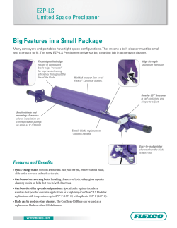
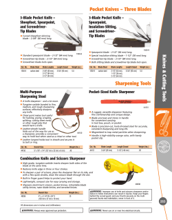
Technical Description
Crawler Tractor
PR 742 B
litronic`
Engine output 172 kW/234 HP
Operating weight 23.0 – 27.6 t/50,700 – 60,900 lb
Hydrostatic travel drive with electronic steering control
The Better Machine.
Diesel Engine
Liebherr-Diesel Engine ____
Rating per ISO 9249 ________
Displacement __________________
Bore/stroke ____________________
Design ____________________________
Injection
Fuel filter
________________________
______________________
Lubrication
____________________
Operating voltage ____________
Alternator ______________________
Starter ____________________________
Batterie __________________________
D 926 TI-E
234 HP (172 kW) at 1800 RPM
10 l (610 cu.in.)
122/142 mm (4.8/5.6 in.)
6 cylinder in-line engine, water-cooled,
turbocharged, intercooled
direct fuel injection with in-line injection
pump, mechanical governor
pre-cleaner with water separator and
microfilters
pressurized lube system with full flow
filter and integrated oil cooler, deep oil
pan for inclinations, engine lubrication to
an inclination of up to 45h to each side
24 V
55 Amp.
6.6 kW (9.0 HP)
143 Ah
Travel Control
1 Joystick lever
with electronic control for all travel functions: travel direction, speed, steering and
counter-rotation
__________
Speed range 1
0 – 4 km/h (0 to 2.5 mph)
__________
Speed range 2
0 – 6.5 km/h (0 to 4 mph)
Speed range 3 __________ 0 – 11 km/h (0 to 6.8 mph)
Electronic engine speed
sensing control __________ electronic regulation assures a constant
balance between travel speed and necessary
drawbar pull through engine speed sensing
avoiding engine overload, even in partial
load range
Straight line travel ____ electronically controlled
Parking/emergency
brake ________________________ automatically applied after the joystick lever
is put in neutral position
Safety lever ______________ inactivates complete travel and working
hydraulic circuit and automatically activates
parking brake
Emergency shut off __ push button on instrument panel immediately activates parking and emergency brake
________
Travel Drive
Design ____________________________ closed-loop hydrostatic drive, each track
is driven by one variable flow swash
plate-type pump and one variable displacement motor
______________________
Pump flow
max. 272 l/min (72 gpm)
________________
Max. pressure
adjusted to 420 bar (6090 PSI)
__________________
Travel speed
0 – 11 km/h (0 to 6.8 mph) infinitely
variable, forward and reverse
Steering ________________________ hydrostatic
Service brake __________________ hydrostatic
Parking/emergency
brake ____________________________ automatic multi disc brake in final drives
Cooling system ______________ hydraulic oil cooler with separate cooling
circuit with gear pump and front mounted
cooler
Filter system __________________ cartridge microfilters in the cooling circuit
Final drive ______________________ 2-stage planetary reduction gear
Implement Hydraulic
Hydraulic system
______
Pump flow ________________
Pressure limitation ____
Control valve ____________
Filter system
Control
____________
____________________
load sensing proportional pump flow control,
variable flow swash plate piston pump and
pressure compensation
max. 292 l/min. (77 gpm)
max. 160 bar (2320 PSI)
2 spool control block, can be expanded to
4 circuits
return filter with magnetic rod in hydraulic
tank
single servo-assisted joystick lever for blade
hoist and tilt functions, electrically controlled
blade float and quick drop
Attachments
Front side
________________
Rear side __________________
Pivot points ______________
straight blade, semi-U-blade or angle blade
with hydraulic tilt device
ripper, hydraulic winch or swinging drawbar
maintenance-free, with hardened and
polished pins and bushings
Operator’s Compartment
Cab
__________________________
Operator’s seat __________
Instrument panel
Ventilation
Track Frame
Design ____________________________ maintenance-free standard, long (L) or
low ground pressure (M) tractor-type
track frames
Mount ____________________________ elastic components at a separate pivot
shaft and an oscillating equalizer bar,
oscillation ± 3h
Chains ____________________________ lubricated, track chain tension via grease
tensioner and hydraulic cylinders, single
grouser pads
Chain links ____________________ 40 (43 on PR 742 B-L and B-M)
Sprockets ______________________ 5 replaceable segments
Track rollers __________________ 7 (8 on PR 742 B-L and B-M)
Carrier rollers ________________ 2
Technical Data
2
______
________________
Heater ______________________
Noise level ________________
resiliently mounted, with integrated ROPS
(Roll Over Protective Structure, SAE J 1040/
ISO 3471) and FOPS (Falling Objects Protective Structure, SAE J 231/ISO 3449), can be
tilted with hand pump to 40h to the rear for
accessibility to machine components, diagonally arranged doors, all around safety glass
fully adjustable, suspended swing seat, adjustable to operator weight
comprehensive instrument panel on the right
side of the operator’s seat
pressurized filtered air ventilation, 3 stage
blower, 8 air nozzles, sliding windows on
both sides and in the rear
hot water heater
82 dB(A) on job location, conforms to EG
standard 86/662/EWG
Refill Capacities
Fuel tank ________________________________________________________________ 450 l (119
Cooling system __________________________________________________________ 62 l (16.4
Engine oil __________________________________________________________________ 22 l (5.8
Splitterbox __________________________________________________________________ 3 l (0.8
Hydraulic tank __________________________________________________________ 189 l (50
Final drive, each ____________________________________________________________ 23 l (6
gal)
gal)
gal)
gal)
gal)
gal)
Basic Machine
A
B
G
E
F
D
C
I
H
PR 742 B
Dimensions
A
B
C
D
E
F
G
H
I
Height over cab
Height over engine cover
Overall length without attachments
Distance idler/sprocket center
Height of grouser
Track gauge
Ground clearance
Width over frame mounting trunions
Overall width with
pad size: 20”/508 mm
24”/610 mm
28”/710 mm
32”/812 mm
36”/914 mm
Ground contact area with
pad size: 20”/508 mm
24”/610 mm
28”/710 mm
32”/812 mm
36”/914 mm
PR 742 B-L
PR 742 B-M
ft-in/mm
ft-in/mm
ft-in/mm
10’10”/3305
7’10”/2386
14’1”/4300
9’9”/2960
21/2”/72
6’6”/1980
1’7”/482
9’9”/2974
10’10”/3305
7’10”/2386
14’1”/4300
10’9”/3275
21/2”/72
6’6”/1980
1’7”/482
9’9”/2974
10’10”/3305
7’10”/2386
14’1”/4300
10’9”/3275
21/2”/72
7’2”/2180
1’7”/482
11’1”/3374
8’9”/2680
8’9”/2680
8’10”/2690
–
–
8’9”/2680
8’9”/2680
8’10”/2690
–
–
–
–
–
9’10”/2992
10’2”/3094
4650 sq.in./3.0 m2
5580 sq.in./3.6 m2
6510 sq.in./4.2 m2
–
–
5115 sq-in./3.3 m2
6200 sq.in./4.0 m2
7130 sq.in./4.6 m2
–
–
–
–
–
8215 sq.in./5.3 m2
9300 sq.in./6.0 m2
Dimensions
3
Straight Blade / Semi-U-Blade
A
H
T
K
U
B
P
N
Straight Blade
PR 742 B
Blade capacity (ISO 9246)
Dimensions
A
B
H
K
P
T
U
N
Blade height
Blade width
Blade lifting height
Blade drop below ground
Max. blade pitch
Max. blade tilt
Overall length
Track pad width
Operating Weights *
Basic machine with blade and
track pad width of: 20”/508 mm
24”/610 mm
28”/710 mm
32”/812 mm
36”/914 mm
Ground Pressures
Basic machine with blade and
track pad width of: 20”/508 mm
24”/610 mm
28”/710 mm
32”/812 mm
36”/914 mm
Attachments
4
PR 742 B-L
Semi-U-Blade
PR 742 B-M
PR 742 B
PR 742 B-L
8.33 cu.yd./6.37 m3 8.33 cu.yd./6.37 m3 8.20 cu.yd./6.27 m3 9.7 cu.yd./7.42 m3 9.7 cu.yd./7.42 m3
ft-in/mm
ft-in/mm
ft-in/mm
ft-in/mm
ft-in/mm
4’9”/1450
13’1”/3990
3’9”/1155
1’9”/525
10h
3’3”/980
17’11”/5460
20”/24”/28”/
508/610/710
4’9”/1450
13’1”/3990
3’10”/1175
2’/605
10h
3’3”/980
18’11”/5775
20”/24”/28”/
508/610/710
4’5”/1350
14’9”/4500
3’10”/1175
2’0”/600
10h
3’0”/910
18’11”/5770
32”/36”/
812/914
4’11”/1500
12’2”/3700
3’9”/1145
1’8”/520
10h
3’/910
18’6”/5645
20”/24”/
508/610
4’11”/1500
12’2”/3700
3’10”/1165
2’/600
10h
3’/910
19’7”/5960
20”/24”/
508/610
lb/kg
lb/kg
lb/kg
lb/kg
lb/kg
50,600/22,950
51,500/23,350
52,400/23,750
–
–
52,250/23,700
52,250/23,700
53,900/24,450
–
–
–
–
–
54,200/24,600
55,000/24,950
50,600/22,950
51,800/23,350
–
–
–
52,300/23,700
53,100/24,100
–
–
–
PSI/kg/cm2
PSI/kg/cm2
PSI/kg/cm2
PSI/kg/cm2
PSI/kg/cm2
10.81/0.76
9.25/0.65
8.11/0.57
–
–
10.24/0.72
8.39/0.59
7.54/0.53
–
–
–
–
–
6.54/0.46
5.97/0.42
10.81/0.76
9.25/0.65
–
–
–
10.1/0.71
8.53/0.60
–
–
–
Angle Blade With Hydraulic Tilt Device
H
A
T
K
P
B
U
G R
B1
N
Y
U1
Blade capacity (ISO 9246)
Dimensions
A
B
B1
H
K
P
Y
T
G
R
U
U1
N
Height of blade
Width of blade
Transport width
Blade lifting height
Blade drop below ground
Max. blade pitch
Blade angled
Max. blade tilt
Width over frame mounting trunions
Width over C-frame
Overall length, blade straight
Overall length with blade angled
Track pad width
Operating Weights *
Basic machine with
blade and trackpads 20”/508 mm
24”/610 mm
28”/710 mm
Ground Pressures
Basic machine with
blade and trackpads 20”/508 mm
24”/610 mm
28”/710 mm
PR 742 B
PR 742 B-L
6.41 cu.yd./4.9 m3
6.41 cu.yd./4.9 m3
ft-in/mm
ft-in/mm
3’11”/1200
15’1”/4590
14’0”/4175
4’0”/1210
1’11”/580
10h
25h
2’5”/735
9’9”/2974
10’6”/3200
19’1”/5810
22’0”/6700
20”/24”/28”/508/610/710
3’11”/1200
15’1/4590
14’0”/4175
4’0”/1285
1’11”/645
10h
25h
2’5”/735
9’9”/2974
10’6”/3200
20’1”/6125
23’0”/7015
20”/24”/28”/508/610/710
lb/kg
lb/kg
51,000/23,150
51,900/23,550
52,600/23,850
52,500/23,800
53,350/24,200
54,100/24,550
PSI/kg/cm2
PSI/kg/cm2
10.95/0.77
9.25/0.65
8.11/0.57
10.24/0.72
8.53/0.60
7.54/0.53
5
Single Shank Ripper
3-Shank Ripper
B
X
B
X
D
A
A
C
C
E
E
H
G
F G
H
1-shank rigid type
Dimensions
A Ripping depth
B Lifting height
C Overall length
attachment raised
E Overall length
attachment lowered
G Width
X Slope angle
Weight
Ripper complete
Attachments
6
3-shank rigid type
ft-in/mm
2’8”/1’10”/805/565
2’9”/3’4”/840/1010
5’6”/4’11”/1680/1490
6’8”/2030
3’8”/1115
25h/32h
lb/kg
4400/2000
Dimensions
A Ripping depth
B Lifting height
C Overall length
attachment raised
D Ground clearance below toolbar
E Overall length
attachment lowered
F Ripping width
G Toolbar width
H Distance between teeth
X Slope angle
Weight
Ripper complete
ft-in/mm
2’1”/1’5”/625/425
1’9”/2’5”/540/740
3’8”/1130
10”/260
5’6”/1675
6’9”/2070
7’10”/2400
3’3”/1000
29h/36.5h
lb/kg
5750/2600
Swinging Drawbar
Winch
F
G
H
H
E D
A
I
C
C
G
J
B
D
A B
E
A B
F
Max. line pull: 520 kN/53,0 t/116,800 lb
Max. line speed: 0 – 80 m/min./0 – 262 ft/min.
Cable size: 28 mm/11/8”
Cable length: 60 m/197 ft
Swivelling Design
Dimension
ft-in/mm
Dimensions
A
B
C
D
E
81/2”/210
1’4”/400
1’10”/565
1’7”/475
A
B
C
D
E
F
G
H
I
J
Swing angle min.
Swing angle max.
Height of drawbar
Ground clearance below drawbar
Ground clearance below drawbar
suspension
F Overall length
G Pin diamenter
H Size of opening
Weight
Swinging drawbar
1’4”/410
1’5”/425
2”/50
31/2”/95
lb/kg
1100/500
Height, cable exit
Overall length
Height drawbar
Drum diameter
Coiling width
Flange diameter
Distance to center of drum
Height of drum center
Total height
Hook radius of winch
Weight
Winch complete
ft-in/mm
4’4”/1325
2’5”/740
1’8”/510
111/2”/290
111/2”/290
2’0”/600
1’5”/440
3’10”/1170
5’3”/1600
1’5”/425
lb/kg
5620/2550
7
Basic machine
Operator’s cab
Cover engine hood
Cover oil cooler
Exhaust catalyst
Tow switch
Towing hitch rear
Towing lug front
Forestry equipment
Woodchip handling equipment
Coal handling equipment
Landfill equipment
Battery compartment lockable
Filling with environmental friendly oil
Filling with oil SAE 10
Filling with oil SAE 30
Tank guard complete
Tank guard bottom
Refuelling pump electrical
Belly pans heavy duty
Fire supression system engine compartment
Connector external electric power
Cold start device ether
Cold start device glow plug
Radiator coarse mesh
Radiator guard 2-piece, hinged
Liebherr Diesel engine
Fan – hydraulically driven
Fan guard
Engine oil cooler
Engine doors perforated
Engine doors hinged, lockable
Lugs for crane lifting
Platform rear
Special paint
Settling pund equipment
Fuel water separator
Fuel water separator with electric heater
Air filter dry-type, dual step
Wear guard for radiator
Precleaner with automatic dust ejector
Preheater for engine electric
Tool kit in batteries compartment
NEW!
x
x
x
x
x
NEW!
NEW!
x
x
x
x
x
x
x
x
x
x
x
x
Option
x
x
x
x
x
x
x
x
x
x
x
x
x
x
x
x
x
x
x
x
x
x
x
x
x
x
NEW!
x
x
x
x
x
x
x
x
x
x
x
x
x
x
x
x
x
x
x
x
x
x
x
x
x
x
x
x
x
x
x
x
x
x
x
x
x
x
x
x
x
x
x
Instruments – Indicators
Battery charging
Hour meter
Electronic control
Speed range
Engine oil pressure
Water temperature
Oil pressure cooling circuit
Oil level final drives
Float position blade
Fuel level
Contamination hydraulic filter
Contamination air filter
Cold start Diesel engine
Hydraulic control 6-way-blade
Hydraulic control ripper
Hydraulic control winch
Variable flow pump, load sensing
Oil filter with strainer in hydraulic tank
Blade quick drop
Blade float position
Control block for 2 circuits
Hydraulic tank oil level control
Hydraulic servo control
x
x
x
x
x
x
x
x
x
x
x
x
x
x
x
x
x
x
x
x
x
x
x
x
x
x
x
x
x
x
x
x
x
x
x
Attachments
Mounting plate rear for external tools
Drawbar rear hinged
Drawbar rear rigid
Counterweight rear
Ripper single shank
Ripper 3 shank
Ripper 5 shank
Bumper rear
Rake for landclearing
6-way-blade inside mounted
6-way-blade outside mounted
6-way-blade with hinged corners
Blade – straight blade
Blade – semi-U-blade
Blade – trimming blade
Blade – U-blade
Blade – angle blade
Blade – woodchip-U-blade
Blade – coal-U-blade
Blade – landfill blade
Push plate
Winch
Rock guard for semi-U-blade
Spill plate
Wear plates for push arms
Wear plates for blades
LIEBHERR-WERK TELFS GMBH, Hans-Liebherr-Straße 35, A-6410 Telfs, ç (0 52 62) 6 00, Fax (0 52 62) 6 00 72
www.liebherr.com, e-Mail: [email protected]
With compliments:
x
x
Option
x
Electrical system
Starter motor 6,6 kW
Starter motor 9 kW
Working lights rear 2 units
Working lights front 2 units
Battery main switch electric
Batteries, heavy duty cold start
On-board system 24 V
Alternator 24 V
Alternator 55 A
Alternator 80 A
Back-up alarm
Beacon
Horn
Start lock electronic
Lights additional rear 2 units
Ligths additional on lift cylinders
Lights additional on engine hood
Standard
x
x
x
Implement hydraulic
Undercarriage
Resilient mounting
Track shoes extreme service (ESS)
Track frame closed
Sprocket segments bolt-on
Master link 2 piece
Track shoes with relief holes
Tracks oil lubricated
Track guide center part
Track guard
Undercarriage extented
Undercarriage low ground pressure
Undercarriage standard
Undercarriage extra wide tracks
Track frames oscillating +/- 3h
Pivot shaft separate
Sprocket segments with recesses
NEW!
x
Travel drive
Parking brake automatic
Function control automatic
Control – single lever
Load limit control electronic
Travel control electronic
Travel control 2-speed
Travel control 3-speed
Hydrostatic travel drive
Emergency stop
Oil cooler
Final drives planetary gear
Safety lever
Stowing box
Armrest adjustable
Ash tray
Rear mirror outside left
Pressurizer with air filter
Operator’s seat 6-way adjustable
Operator’s seat air suspended
Fire extinguisher
Dome light
Coat hook
Air conditioner
FM radio
Radio installation kit
ROPS-canopy
ROPS/FOPS-cab sound supressed
Rear mirror inside
Windscreen washer
Windscreen wipers front, rear, doors
Sliding windows
Protective grids for windows
Safety glass tinted
Sun blinds
Extra cab heater
Cabin heater warm water
x
x
x
x
x
x
x
x
x
x
x
x
x
x
x
x
x
x
LWT/VM 8434218-1-09.02 Printed in Germany by BVD. Illustrations and data may differ from standard equipment. Subject to change without notice.
Standard


© Copyright 2026