
A-12142 Heater kit to fit John Deere 2032R, 2520, 2720
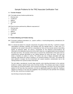
12/16/2014
INSTALLATION INSTRUCTIONS
John Deere 2520, 2720, 2025R and 2032R Series
A-12142
HEATER KIT
With Diesel Engine Connection Fittings
Figure 1
(General Layout and Parts I.D.)
05-11578
Page 1 of 6
12/16/2014
INSTALLATION INSTRUCTIONS
John Deere 2520, 2720, 2025R and 2032R Series
Read these instructions and identify all components. Please retain these instructions for future
reference and parts ordering information. Refer to kit components and Figure 1 for general layout.
Note: Cab kit A-11858 must be installed prior to installing this kit!
Kit Components:
ITEM
1
2
3
4
5
9
10
11
12
13
14
15
16
17
18
19
20
21
22
23
24
25
26
27
28
29
30
QTY
1
8
2
3
1
1
1
1
2
1
1
1
4
4
4
4
1
2
1
1
3
3
3
1
1
2
1
P/N
3-17100
3-16629
3-19594
3-17517
3-18819
4-15815
3-20137
3-11220
3-13442
1-49570
3-12119
3-20284
3-10858
3-16217
3-18187
3-19335
3-18259
3-16823
3-16057
3-20500
3-11255
3-19338
3-20329
3-10704
3-10364
3-10670
3-10345
DESCRIPTION
PUSH/PULL CABLE
NYLON TIE
NYLON TIE WITH 1/4" RETAINER
NYLON TIE MOUNT PSA BACK
PULL FOR HEAT DECAL
HEATER ASSEMBLY
Y-FITTING, 1.125"
VALVE, SHUT-OFF
HOSE CLAMP, LARGE, #16
HOSE, ELBOW, 5/8" X 16" LG
FITTING, BRASS, 3/8" NPT TO 5/8" HOSE BARB
FITTING, ALUMINUM
HOSE CLAMP, #10
WASHER, RUBBER, GLASS
WASHER, FENDER, 5/16"
BOLT, 5/16"x1.00" LONG, TORX BUTTON HEAD
NUT, JAM M16-1.5
O-RING
FUSE, BLADE TYPE, 10 AMP
WINDOW, FRONT RH ACRYLIC
P-CLAMP, DUAL HOSE
BOLT, 5/16"x1/2" LONG, TORX BUTTON HEAD
NUT, NYLOCK FLANGE, 5/16"
DUCT, PLASTIC LOOM, .350 ID X 76" LONG
WIRE, RED 14 GA, 76" LONG
TERMINAL CONNECTOR, 14 GA X 1/4" BLADE FM
WIRE, BLACK 14 GA, 76" LONG
Preparation of Tractor;
1. Park tractor on level surface and turn ignition key off.
2. Allow engine to cool. Drain coolant from radiator.
Mounting the heater unit;
3. Remove lower RH front window from cab and remove seals from window.
4. Install seals onto new acrylic window (23) (Figure 2).
5. Apply pull for heat decal (5) onto acrylic window (23) 7/16” hole location (Figure 2).
6. Install push/pull cable (1) into acrylic window (23) 7/16” hole and secure to window using hardware
supplied with push/pull cable (Figure 2).
7. Secure heater assembly (9) onto the inside surface of the acrylic window (23) using (Figure 2);
(4) 5/16” x 1.00” button torx head bolts (19)
(4) 5/16” rubber washers (17)
(4) 5/16” fender washers (18)
8. Install new window with seals and heater unit onto lower RH front cab location.
05-11578
Page 2 of 6
12/16/2014
INSTALLATION INSTRUCTIONS
John Deere 2520, 2720, 2025R and 2032R Series
STEP 6
BUBBLE
SIDE
STEP 5
STEP 4
STEP 7
ITEM
23
Figure 2
STEP
11
STEPS
12 & 16
STEP
10
STEPS
13 & 15
STEPS
14 & 17
Figure 3
Figure 4
Supply connection from engine to heater unit;
9. Locate temperate sensor near engine’s thermostat area. Remove temperature sensor with washer.
10. Thread M16 jam nut (20) onto M16 male thread on aluminum fitting (15), to the fitting shoulder
(Figure 3).
11. Thread 4-way O-ring washer (21) onto M16 male thread on aluminum fitting (15) (Figure 3).
12. Disconnect engine temperature sensor wire and remove engine temperature sensor (Figure 4).
13. Install aluminum fitting with O-ring and nut, into sensor port until O-ring makes contact (Figure 4)
Thread tape may be used.
14. Orientate fitting so that the brass fitting (14) for the heater hose can be easily installed (Figure 4).
15. Using the M16 jam nut, unscrew the nut until the nut makes contact with the O-ring and becomes
tight, preventing the aluminum fitting from rotating (Figures 4 & 5).
05-11578
Page 3 of 6
12/16/2014
INSTALLATION INSTRUCTIONS
John Deere 2520, 2720, 2025R and 2032R Series
16. Re-install temperature sensor with remaining rubber O-ring, into the end of aluminum fitting (15)
(Figures 4 & 5). Thread tape may be used.
17. Install brass fitting (14) into aluminum fitting side using thread seal tape (Figures 4 & 5).
18. Connect 5/8” x 17.00” long heater hose elbow (13) to brass fitting (14) and secure using a small hose
clamp (16).
19. Connect shut-off valve (11) to remaining end of 5/8” x 17” long heater hose elbow (13) and secure
using a small hose clamp (16) as show in Figure 5. Connect valve as shown.
20. Select one of the two 5/8” heater hose from heater assembly (6) to remaining end of shut-off valve (8)
and secure using a small hose clamp (13).
21. Connect push/pull cable (1) loop end to shut-off valve (11) and secure using hardware supplied with
valve.
To heater
STEP 16
(INSTALL SENSOR)
STEP 21
STEP 19
STEP 17
STEP 18
STEP 20
FLOW
FROM
ENGINE
PORT
Figure 5
Return connection from heater unit to engine (Figure 6);
22. Locate lower radiator hose. Cut hose and install the Y-fitting (10) as shown in Figure 6.
23. Secure using large hose clamps (11).
24. Connect remaining end of 5/8” heater hose from heater assembly (9) to 5/8” nipple on Y-fitting (10)
and secure using small hose clamp (11).
STEP 24
From heater
STEPS 22 & 23
To engine
STEPS 22 & 23
From radiator
Figure 6
Connecting power;
25. Using a wire crimping tool, extend heater unit to wires harness using both red (28) and black (30)
wires supplied with kit. Route wires upward to overhead switch panel.
26. Remove (4) over head switch panel bolts and lower switch panel.
05-11578
Page 4 of 6
12/16/2014
INSTALLATION INSTRUCTIONS
John Deere 2520, 2720, 2025R and 2032R Series
27. Select an empty fuse block location and connect red wire (28) using a ¼” female terminal connector
(29) to selected location.
28. Connect black wire (30) to ground terminal located on fuse block ground bar using a ¼” female
terminal connector (29).
29. Install protective wire loom (27) over wires.
30. Install 10 amp fuse (22) into selected location from step 27.
Completing Installation;
31. Refill radiator.
32. Start tractor and turn heater switch on and off to check blower operation.
33. Pull and push cable several times to activate valve and allow coolant to circulate through the heater.
34. Shut engine off and check coolant. This may take several attempts to purge all the air from the
system.
Securing heater hoses;
35. Measure 4 inches from front window and secure heater hoses together using (Figure 5);
(1) Double P-clamp (24)
(1) 5/16” x 1/2” long bolt (25)
(1) 5/16” hex flange nylock nut (26)
36. Secure remaining locations of heater hoses together and to frame use existing holes already in the
frame. Secure to frame using (Figure 6);
(2) Double P-clamp (24)
(2) 5/16” x 1/2” long bolt (25)
(2) 5/16” hex flange nylock nut (26)
STEP 36
STEP 35
Figure 8
Figure 7
37. Secure loose wires and hoses using nylon ties supplied with kit. Do not secure wires or hoses to
high pressure fuel lines, hot surfaces or moving components.
Note: Shut-off valve should be in the “OFF” position when heat is not needed. If overhead panel is wired
correctly, the heater fan should turn off when ignition key is turned off.
MODEL
FUEL
HP
BRAND
TRANS
2520
2025R
2720
2032R
DIESEL
DIESEL
DIESEL
DIESEL
26.4
24.2
31.4
31.7
YANMAR
YANMAR
YANMAR
YANMAR
4WD
4WD
4WD
4WD
ALTERNATOR
AMPS
40
20
40
40
SOURCE
CONNECTION
M16 SENSOR PORT
M16 SENSOR PORT
M16 SENSOR PORT
M16 SENSOR PORT
RETURN CONNECTION
LOWER RADIATOR HOSE Y
LOWER RADIATOR HOSE Y
LOWER RADIATOR HOSE Y
LOWER RADIATOR HOSE Y
Installation is now complete. If you have any questions or comments, contact;
Revised instructions 10-10-14 by CAD; Added jam nut (20) & aluminum fitting (15) was 3-17262.
Revised instructions 12-16-14 by CAD; Added (1) additional O-ring, 3-16823.
05-11578
Page 5 of 6
12/16/2014
INSTALLATION INSTRUCTIONS
John Deere 2520, 2720, 2025R and 2032R Series
05-11578
Page 6 of 6


© Copyright 2026