
gulf intracoastal waterway barge gate
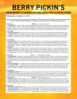
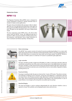
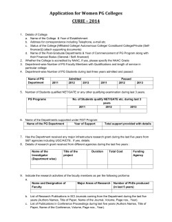
# 33
newsletter
DECEMBER 2014
Gerwicknews
Gulf Intracoastal
Waterway BARGE GATE
Barge gate photos: top – structure nearing
completion in dry dock, middle – under tow,
bottom – trial fit-up installation during flood
wall construction period. Top photo courtesy
of USACE Team New Orleans. Bottom photos
courtesy of CB&I (formerly Shaw E&I).
president’s message
As part of the 2014 Outstanding Civil
Engineering Achievement (OCEA) Award from
ASCE for the Inner Harbor Navigation Canal Surge
Barrier, the Gulf Intracoastal Waterway Barge Gate reduces
the risk of hurricane storm surge flooding in New Orleans.
gulf intracoastal
waterway barge GATE
PHILLIPS 66 RICHMOND
TERMINAL MOTEMS AUDIT
AND UPGRADES
Content
MOORING ANALYSES
TECHNICAL REVIEW OF
THE MID-BARATARIA
SEDIMENT DIVERSION
EMPLOYEE SPOTLIGHT
Gerwick designed a unique, reinforced,
lightweight concrete barge gate to close
a 150 foot-wide navigation channel in
the Gulf Intracoastal Waterway (GIWW).
Among other awards, the floating gate won
the 2013 National Council of Structural
Engineers Award of Excellence for Bridges
and Transportation structures.
Originally the barge gate was intended
to close a temporary navigation channel
during construction of the overall project.
However, analysis of the tidal fluctuation
revealed that large flow velocity would
hamper navigation through an adjacent
sector gate. Therefore the barge gate
was revised to function as a permanent,
operational gate to normally remain open to
decrease the flow velocity. It is closed for
maintenance or a storm. In addition, the
barge gate provides a navigation channel
during maintenance of the sector gate.
CONTINUED ON PAGE 3
# 33
newsletter
DECEMBER 2014
2
PRESIDENT’S
MESSAGE
Winston Stewart, PE
[email protected]
locations
1300 Clay Street, 7th Floor
Oakland, CA 94612
Tel: (510) 839-8972
3780 Kilroy Airport Way #200
Long Beach, CA 90806
Tel: (562) 598-9888
220 West Mercer St., #W-100
Seattle, WA 98119
Tel: (206) 588-2735
400 Poydras St., #1160
New Orleans, LA 70130
Tel: (504) 528-2004
CONTACTS
Offshore Marine Structures
Dale Berner, PhD, PE, FASCE
[email protected]
Tunnels, Pipelines, and Immersed Tubes
Henrik Dahl, PE
[email protected]
Wharves, Piers, Ports, and Harbors
This issue of GerwickNews may
become a souvenir for many, as
it will be the last issue published
under the Ben C. Gerwick, Inc.
banner. On January 1, 2015,
Gerwick will formally merge with
sister COWI NA, Inc. company,
Ocean & Coastal Consultants
to form COWI Marine NA. The
legal entity will be COWI NA, Inc.
and COWI Marine NA will be a
business unit thereof.
I will head the new company
and my counterpart at OCC,
John Chapman, will be the
market director. Our clients
can expect the same quality
of service to which they are
accustomed. In addition, our
clients will have direct access
to a wider menu of professional
engineering services through
one company, COWI Marine
NA. In essence, they will have a
one-stop shop.
Inside this issue, our readers are
provided an insight into some
of the most challenging and
interesting projects that Gerwick
is privileged to be engaged in.
The Gulf Intracoastal Waterway
Floating Gate is a signature
feature of the IHNC Storm
Surge Barrier in New Orleans.
It is the winner of one of the
highest honors in the structural
engineering world, the 2013
National Council of Structural
Engineering Associations
(NCSEA) Excellence in
Structural Engineering Award
(New Bridges & Transportation
Structures).
The Phillips 66 Richmond
Terminal MOTEMS Audit and
Upgrades article is a real gem,
engagingly and limpidly describing the audit and the solutions
that we engineered.
The Mid-Barataria Sediment
Diversion (MBSD) for the
Coastal Protection & Restoration
Authority (CPRA) in Louisiana is
the first major diversion initiated
by the CPRA. Here, we developed Value Engineering (VE)
concepts to reduce costs and
improve quality using “in-thewet” and “offsite pre-fabrication”
construction techniques.
The mooring analysis article
introduces the procedures and
benefits of doing such analyses.
Gerwick has performed mooring
analyses throughout the U.S.
and internationally. Our staff
keeps abreast of the latest
methods and tools for mooring
analyses, thereby ensuring that
our clients profit from the most
relevant industry practices.
I encourage readers to peruse
the lists of Gerwick’s recent
awards and presentations as
well as Paul Guenther’s biography.
In closing, may this holiday
season be especially gratifying
for all of our employees, clients
and friends of the company.
Ted Trenkwalder, PE, SE
[email protected]
Water Resources, Waterways, and
Concrete Technology
Sam Yao, PhD, PE
[email protected]
Geotechnical and Foundations
Winston Stewart, PE
[email protected]
www.gerwick.com
www.cowi.com
www.b-t.com
www.ocean-coastal.com
www.jennyeng.com
about ben c. gerwick, inc.
Gerwick is an internationally renowned engineering consulting firm that has specialized in the design of marine
structures for over 80 years. Our highly qualified staff of civil, structural, geotechnical and coastal engineers has
worldwide design and construction engineering experience with piers and wharves, bridges, inland navigation
waterways, offshore terminals and platforms, dry docks, harbor facilities, and deep foundations.
We have a proven record of accomplishment for producing reliable, economical, innovative, and constructible
designs for some of the most challenging design-build and design-bid-build projects. We are experienced in
delivering both small and large projects locally, nationally and globally. We were proud to be included in the
Engineering News-Record Design Firms Sourcebook 2013, where we were ranked as one of the top ten firms
under Marine and Port Facilities.
Since 1987, Gerwick has been affiliated with COWI A/S of Denmark. COWI provides services within
the field of marine, geotechnical and coastal engineering from six worldwide centers of excellence. Gerwick is a member of the COWI North America group of companies, which also includes
Vancouver-based firm Buckland & Taylor Ltd., and two east coast-based firms Ocean and Coastal
Consultants, Inc. and Jenny Engineering Corporation. Together we collaborate on marine structures,
bridges, tunnels and coastal engineering projects around the world.
3
Final Preparations for Launch in the Drydock in
Sulphur, LA, 1/2011
barge gate (continued from cover)
Barge Gate
Description
The barge gate is 190 ft long, 62.5 ft wide,
43.5 ft tall, weighs 5,200 dry tons, and floats
at a 14 ft draft. When closed to resist storm
surge, it is ballasted to rest on an underwater foundation and abutment. The design
requirements include ability to withstand
hydrostatic and hydrodynamic loading up
to EL +26 ft, allow some wave overtopping,
provide for uneven foundation contact,
provide a roadway for a truck to access the
flood wall, float with a maximum draft of
14.5 ft, and to withstand a tow in the Gulf of
Mexico. Intended design life is 100 years in
a marine environment using a marine lightweight concrete mix, normal steel reinforcing
bars, and construction joints that can be
resealed with embedded injection hoses in
the event of future leaks. Significant design
features include vessel impact resistant
walls, a 1 ton/ft2 pressure hull, 1 ksf deck
loads, 1,200 kip surge brackets, and 400
kip (ultimate) towing bollards. Other features
include an electro-mechanically operated
chain-windlass system for opening and
closing and a fiber-reinforced epoxy (FRE)
ballast system. The ballast system includes
marine grade stainless steel embeds and
FRE anchor flanges cast into the structure to
achieve 100-year design life.
Structural Layout
The barge gate has four deck levels: a keel
deck (bottom at EL -17.5 ft), a middle deck
(at EL +5 ft), a mechanical deck (at EL +15
ft) and a top deck at EL +26 ft. Transverse
frames and walls are provided on 17’-6”
maximum spacing and a watertight longitudinal centerline wall is provided between
the keel and middle decks. The longitudinal
centerline wall combined with two internal
transverse shear walls located at 1/3 of the
distance from each end form six internal
tank compartments for ballast water.
Above the middle deck the transverse cross
section is asymmetrical saving structural
weight to reduce vessel draft. The cross
section geometry eliminates heel and trim.
When open, resistance to vessel impact on
the barge gate wall parallel to the bypass
channel is provided by a 19 inch thick vessel
impact wall with embedded steel sections.
When closed, the top deck provides a
roadway for an AASHTO HS-10 truck to
access the flood wall for maintenance.
aggregate (Stalite) with low water absorption. After processing in a rotary kiln, it has
a 24 hour water absorption of 6% whereas
other lightweight aggregates have water absorptions ranging from 15% to 30%. Water
absorption for Stalite increases to 9% during
mixing or pumping concrete. Stalite meets
the requirements of ASTM C330 which
covers lightweight aggregates intended for
use in structural concrete in which the prime
considerations are reducing the density
while maintaining the compressive strength
of the concrete. For the 3,250 cubic yards
of concrete placed, the average unit weight
was 110.3 pcf (wet) as determined in
accordance with ASTM C 138. The average
28 day compressive strength was 6,700 psi.
To ensure this high-strength, lightweight mix
could be placed properly and satisfy testing
requirements, the specifications required the
contractor to conduct trial wall pours prior
to constructing the barge gate. The final
successful trial wall pour using the Stalite
mix design was placed using a tower crane
with a 4 cubic yard bucket and tremie pipe
within the wall formwork.
Concrete Mix Design
To achieve a draft limit of 14.5 ft, a maximum
concrete unit weight of 115 pcf (wet) was
specified. The concrete mix design required
a maximum water to cement ratio of 0.4,
a slump range of 6 inch to 8 inch. The
concrete mix design used a lightweight slate
# 33
newsletter
DECEMBER 2014
Structural Layout
# 33
newsletter
DECEMBER 2014
4
Operations
Illustration of Barge Gate at Open Position Foundation
100-Year Design Life &
Corrosion Resistance
To address corrosion, the project specifications provided contractors options to obtain
100-year design life, such as stainless steel
reinforcement or cathodic protection. The
contractor selected for the project, Baker
Concrete, opted to use normal steel reinforcing bars with a concrete mix design containing a calcium nitrite corrosion inhibitor
admixture.
The use of a corrosion-inhibiting admixture
such as calcium nitrite increases the corrosion threshold of carbon steel using 6-15
lb/yd3 (0.15%-0.40%) per unit volume of
concrete depending on dose. This admixture chemically reacts with normal reinforcing
steel, forming an improved oxide layer on the
steel that increases the tolerance of the steel
to chloride. Corrosion initiation is delayed
and corrosion rates are reduced.
The possibility of chloride ion migration
is greatest at construction joints due to
the potential for irregularities such as
honeycombing, air voids, and microcracks.
Therefore construction joints are protected
from chloride ion migration and water
intrusion with PVC waterstops and an
innovative reinjectable-resin Fuko hose
system manufactured by Greenstreak. The
Fuko system injects resin into any irregularities or voids in the construction joint; thus
providing additional protection to chlorideion penetration for bars crossing the joint.
Approximately 8,000 ft of Fuko hose was
installed, making the barge gate the largest
application of Fuko product in Greenstreak’s
history. The Fuko system allows future reinjection of resin into the construction joints
should the need arise.
Outfitting of the barge gate to meet the
design life requirement used stainless steel
for railings, access platforms, watertight
doors, and embedded structural plates. The
barge gate mechanical systems meets the
100 year design life requirement through
the use of: fiberglass reinforced epoxy pipes
(FRE) for ballast system, fiberglass pipe
spools (embedded in walls/slabs), fiberglass
sea chest intakes, stainless steel valves,
stainless steel pipe supports and embedded
unistruts.
Ballast System
The ballast system includes three deep
well pumps which provide a net pumping
capacity of 7,500 gallons per minute.
Included is a bilge system and washdown
system to remove unwanted sediment and
marine debris. These systems have a total
of 430 supports, approximately 1/6 of the
supports required custom designs. Controls
and equipment are provided on board
and located within a control room (240 ft2)
and mechanical equipment room (740 ft2)
underneath the top deck.
An opening/closing chain pull system is
mounted on the barge gate using two
on-board electro-hydraulic powered chainwindlass units with top deck fairleaders
and two underwater swivel fairleaders. The
chain is 1 3/4 inch diameter stud link oil rig
quality with a minimum breaking strength of
380 kips. The chain ends are anchored to a
pulling point in the abutment and to a pulling
structure adjacent to the open position
foundation.
The barge gate will normally be ballasted
and rest on its open-position foundation at
EL -17.5 ft. The open position foundation
consists of thirteen reinforced concrete
grade beams, pile supported and located
to correspond to the barge gate transverse
structural support frame lines. This grade
beam foundation was constructed in the
wet to save the expense of constructing a
temporary cofferdam with tremie slab seal.
When the barge gate needs to be moved
from its open-position foundation to the
closed position, ballast water is pumped out
of its six internal tank compartments and the
gate floats. Once afloat, it pivots 90 degrees
about a pin-pile structure and is pulled open
or closed by the chain-windlass system. It
takes 15 minutes to pull the barge gate from
its open position to the closed position.
As the barge gate nears the foundation
abutment walls, the four stainless steel
fabricated pintel brackets embedded into the
ends of the barge gate align over four abutment pintels (pins). Contact with the pins is
made as the barge gate is ballasted down to
its closed position foundation. The pins are
sloped to pull the barge gate into contact
with a vertical seal on the abutment walls.
As the barge gate nears the foundation base
it makes contact with a foundation perimeter
seal. After this seal is compressed 1 inch
the barge gate vertical loads are transferred
Mechanical Room
5
to foundation base risers which correspond
to the structural framing. The base seal
and vertical seal reduce the hydrostatic
and hydrodynamic uplift on the barge gate,
thereby decreasing the ballast water needed
for a storm event closure and reducing the
time to close the gate (6 hours).
The foundation base risers transfer the
dead load of the ballast water and barge
gate into a pile supported mat foundation.
Lateral load on the barge gate from a storm
is resisted by the foundation sill in contact
with the barge keel slab and by the two
vertical abutment reaction walls parallel to
the channel. This was verified with finite
element modeling. The abutments and mat
are supported by 312 battered piles with a
length of 115 ft and 114 vertical piles with
a length of 109 ft. Piles are prestressed
concrete (2 ft square).
Weight Control
One of the biggest challenges in the design
and construction of the floating barge gate
was monitoring its weight and center of
gravity. Three feet of minimum clearance
from the underwater foundation to the
bottom of the barge gate was required,
resulting in a maximum draft limit of 14.5 ft.
This requirement was complicated by the
functional requirements (added weight) due
to vessel impact walls, strength to withstand
uneven foundation contact, and on-board
equipment. Gerwick developed a 3D CAD
model including internal reinforcement, and
railings/stairs/platforms to aid the calculation of the center of gravity and draft. The
calculated draft left little margin for construction inaccuracies; therefore the project
specifications included tight construction
tolerances, a weight control program and
trial pour mock-up walls.
Each concrete pour was documented by
the contractor for its volume and unit weight
while the center of gravity calculation was
updated and tracked to predict where
ballast would be needed to trim and heel
the barge gate to a level floating plane.
During construction, concrete formwork
was surveyed for compliance with tolerance
specifications to ensure walls were plumb
and bulging did not occur.
Launch and Tow
The barge was built on a floating drydock in
Sulphur, Louisiana. When launched from the
floating drydock the barge gate floated with
slightly less draft than predicted demonstrating success in weight control procedures.
It was then towed approximately 500 miles
through the Gulf of Mexico and up the
Mississippi River to the GIWW. The barge
gate arrived at the GIWW in time for the
2011 hurricane season so that the barge
gate could be installed on its foundation
using tug boats. After arrival at the site,
installation of mechanical and electrical
equipment along and final outfitting were
conducted. The barge gate was installed at
its pivot pile and commissioned for operations in early 2012.
# 33
newsletter
DECEMBER 2014
Haskoning of the Netherlands. The barge
gate was also closed in October 3, 2013 for
Tropical Storm Karen.
Summary
The marine lightweight concrete mix design
with corrosion inhibitor, normal reinforcing
steel, PVC waterstop system with Fuko
hoses, stainless steel embeds, FRE embeds,
and FRE ballast system, produced an
economical structure meeting a 100 year
design life. Gerwick reduced the amount
of ballast and the time to close the gate
before a storm hit, by using an innovative
base seal underneath its perimeter. The seal
also allowed a structural configuration with
a reduced weight to minimize the draft. The
barge gate is able to withstand storm event
waters up to EL +26 ft, a tow through the
Gulf of Mexico, navigation vessel impacts,
and bridge over any potentially uneven
foundation contact points. These features
will help ensure New Orleans is ready for the
next storm.
2012 Hurricane Isaac
On August 28, 2012 Hurricane Isaac made
landfall on the Louisiana coast as a Category
I hurricane with 80 mph winds. This resulted
in a 15 ft storm surge at the barge gate.
This gate prevented an estimated $5 billion
of flood damage as estimated by Royal
project credits
Engineer of Record for Barge Gate Civil, Structural, and Mechanical: Ben C. Gerwick Inc., Oakland, CA
Mechanical Systems Designer: Herbert Engineering, Alameda, CA
Engineer of Record for Barge Gate Electrical: Siver Engineering, Concord, CA
IHNC Project Joint Venture Design Partner: INCA Engineers, Bellevue, WA
Barge Gate Foundation Designer: CB&I (Formerly Shaw E&I), Baton Rouge, LA
Barge Gate Contractor: Baker Concrete Construction, Houston, TX
Barge Gate Mechanical Contractor: Tepsco, Deer Park, TX
Barge Gate Electrical Contractor: RES Contractors, LLC, Plattenville, LA
Concrete Supplier: Port Aggregates, Westlake, LA
Concrete Consultant to Designer: George C. Hoff Consulting, Clinton, MS
Concrete Consultant to Contractor: Concrete Engineering Specialists, Charlotte, NC
Concrete Testing: Louisiana Testing and Inspection, Lafayette, LA
Owner: United States Army Corps of Engineers New Orleans District
DALE BERNER, PHD, PE, FASCE
[email protected]
MICHAEL O’SULLIVAN, SE
[email protected]
MICHAEL GEBMAN, PHD, PE
[email protected]
# 33
newsletter
DECEMBER 2014
6
phillips 66 Richmond
terminal motems audit
and upgrades
Phillips 66 retained the services of Ben C. Gerwick, Inc. for performing the MOTEMS (Marine Oil Terminal Engineering and Maintenance
Standards) Initial Audit of their Richmond marine terminal located
in the Santa Fe Channel of the Richmond Inner Harbor in the San
Francisco Bay. The terminal was built in 1956 and consists of two
reinforced concrete wharves, one 228 feet long by 50 feet wide wharf
for berthing tankers and one 148 feet long by 50 feet wide wharf
for berthing barges. The wharf deck is a cast-in-place reinforced
concrete structure supported on 16” octagonal precast prestressed
concrete piles. A pipeway structure runs parallel to the shore side
of the wharves. The pipeway consists of cast-in-place reinforced
concrete beams supported on 16” precast prestressed concrete
piles. An overhead steel pipeway, built on top of the concrete
pipeway, provides support for the pipelines that run from the tanker
wharf to the Kinder Morgan facility, which is adjacent to the Phillips
66 terminal (See Fig. 1). The two wharves and pipeway have a total
of 190 vertical piles and 64 battered piles.
Gerwick had the role of prime consultant, responsible for planning
the audit and putting together the audit team, collecting the existing terminal information, coordinating the above and below water
inspections, coordinating the sub-consultant work, and assembling
the audit report for submittal to Phillips 66 and the California State
Lands Commission (CSLC). Halcrow participated in the project as
sub-consultant, being responsible for the audit of the fire protection
BERNARDO WAISMAN, PE
[email protected]
system, the piping, and the mechanical and electrical equipment.
The audit report was completed and submitted to the CSLC within
the period specified by MOTEMS for a medium risk facility.
The terminal is classified per MOTEMS as a medium risk facility
because the exposed total volume of oil during transfer is less than
1,200 barrels, the number of transfers per year is greater than 90
and the maximum vessel size is greater than 30,000 DWT.
Phillips 66 uses the terminal for loading and unloading liquid bulk
hydrocarbon products, including bunker fuel, marine diesel oil, and
cutter stock. Adjacent to the Phillips 66 terminal, Kinder Morgan
operates a storage and distribution facility for liquid bulk products
that include one pipeline for handling propylene tetramer, a hydrocarbon that falls within the MOTEMS jurisdiction. Kinder Morgan has
an agreement with Phillips 66 for using the tanker wharf for handling
these products.
During the Initial MOTEMS Audit, the following berthing and structural items were identified as not being in compliance with MOTEMS
requirements: 1) Fender System, 2) Seismic Performance, and 3)
Condition of Concrete Beams, Pile Caps, Columns, and Piles. Upon
evaluating the results of the audit, Phillips 66 initiated a proactive
upgrades program designed to correct the identified deficiencies.
Gerwick was contracted for performing the engineering design and
construction support required for the terminal upgrades.
Figure 1 - Phillips 66 Richmond Marine Terminal
7
# 33
newsletter
DECEMBER 2014
Fender System
Upgrade
The original fender system at the tanker
and barge wharves consisted of vertical
timber piles spaced at 6’-0” on centers
with a timber waler at the top and steel coil
springs that provided the energy absorption
capacity for the berthing of tankers and
barges. During the audit, it was found that
this fender system did not have the capacity
for dissipating the kinetic energy of the
vessels at berthing in accordance with the
MOTEMS requirements. It is important to
indicate that the size of the vessels calling at
the terminal has increased since it was built
in 1956. As a result, the approach angle and
velocity of the vessels currently berthing at
the terminal had to be restricted in order to
avoid damage to the wharf and vessels. The
new fender system consists of rubber cone
fenders with a steel frontal panel of closed
box construction with a UHMW-PE facing
of low coefficient of friction (See Fig.2). Each
fender unit is mounted on a steel frame
supported by two steel wide-flange piles.
Three rubber cone fenders were installed at
the tanker wharf and two rubber cone fenders were installed at the barge wharf. This
new fender system was designed to receive
vessels of up to 76,000 DWT at the tanker
wharf and tank barges of up to 10,000 DWT
at the barge wharf. The design of the new
fenders was performed in strict conformance
with the MOTEMS standards, which require
that each rubber cone fender be capable of
dissipating the total berthing energy of the
design vessel. For the 76,000 DWT tanker,
the design berthing angle and velocity,
normal to berth, were 6 degrees and 0.26
feet per second, respectively. For the 10,000
DWT barge, the design berthing angle and
velocity, normal to berth, were 15 degrees
and 0.33 feet per second, respectively.
The rated energy absorption capacities are
318 kip-ft for the tanker wharf fenders and
122 kip-ft for the barge wharf fenders. An
additional third rubber cone fender was
recently installed at the barge wharf, for
accommodating tug boats that use the new
fueling services provided by Phillips 66.
Figure 2 – New Rubber Cone Fender
structures, including the tanker and barge
wharves, concrete pipeway and overhead
steel pipeway. The overhead steel pipeway,
which supports the pipelines that run from
the tanker wharf to the Kinder Morgan
facility, has an offshore segment built on top
of the concrete pipeway that runs parallel
to the shore side of the wharves and an
onshore segment that starts at the north end
of the barge wharf and ends at the Kinder
Morgan tank farm. The seismic loads and
displacements (demand) were calculated
performing a linear modal site-specific
response spectrum analysis. The analysis
indicated that the structures did not meet
the MOTEMS seismic performance criteria.
The lateral seismic displacements of both
wharves where high, creating strains of
the pile materials above the limiting values
specified in MOTEMS. The calculated
maximum seismic displacement demand
at top of existing piles was 9 inches for
a Level 1 earthquake and 24 inches for
a Level 2 earthquake. The analysis was
done using the computer program SAP
2000. Push-over analyses of the piles were
performed to obtain the maximum allowable
displacements without exceeding the strain
limits. The soil spring values representing the
soil resistance on the piles were based on
the p-y and t-z curves provided by Treadwell
& Rollo. Upper bound and lower bound
spring values and upslope, downslope and
horizontal direction cases were analyzed
to obtain the worst case for top of pile
displacement. All the piles failed for a Level
2 earthquake and a number of piles (the
shorter piles close to shore) failed for a Level
1 earthquake.
Gerwick evaluated two seismic
strengthening schemes. The first scheme
consisted of installing 2 foot diameter
steel pipe battered piles with cast-in-place
concrete caps to resist the seismic loads.
The second scheme consisted of installing
large diameter vertical steel pipe piles
Seismic Upgrade
As part of the MOTEMS Initial Audit, Gerwick
performed a seismic analysis of the terminal
Figure 3 – Upgraded Tanker Wharf Framing Plan
# 33
newsletter
DECEMBER 2014
8
Figure 4 – Driving 66” Diameter Pile at
Tanker Wharf
working as cantilever beams.
The vertical pile scheme
was selected for the seismic
upgrade because of its simpler
construction and lower cost.
The design consisted of
installing 66 inch diameter by
1-1/2 inch thick steel pipe piles,
eight piles at the tanker wharf
and three piles at the barge
wharf. The installed length of the
piles varied from 102 feet to 106
feet. The cast-in-place concrete
pile caps were designed to
transfer only horizontal loads
from the wharf to the pile,
avoiding the transfer of vertical
loads and the application of
bending moments at the top of
the pile. This connection was
achieved with cylindrical steel
sleeves cast in the concrete
before driving the piles. With
this strengthening system, it
was possible to reduce the
seismic displacements to a
maximum of 3 inches for a Level
1 earthquake and 12 inches
for a Level 2 earthquake. (See
Figures 3 and 4).
At the start of the design
process, Gerwick recommended
conducting a pull-out test
program of the existing pile
prestressing strands, with the
Figure 5 – Pipeway Pile Cap with Complete Bottom Repair
purpose of determining if the 24
inch embedment of the strands
into the pile caps had enough
bond capacity to develop the
yield strength of the strands
and allowing the creation of a
moment-resisting plastic hinge.
The results of the tests indicated
that the 24-inch embedment
could develop the yield strength
of the strands. Based on
these results, the pile to cap
connections were modeled as
moment-resisting connections,
which resulted in a simpler and
more cost efficient design.
at both wharves, and seven
prestressed concrete piles.
Gerwick performed a second
and more detailed inspection
of the damaged elements to
obtain the information necessary
for preparing drawings with
the repair procedures and
details. In addition, Gerwick
provided construction support
for the repairs. The materials
for the repairs of beams, pile
caps, columns, and vaults
were manufactured by Sika
Corporation. The materials for
pile repairs were manufactured
by Fox Industries and Sika
Corporation. All the damaged
elements were successfully
repaired and it is estimated
that the repairs will extend
the useful life of the structures
for at least fifteen years (See
Figures 5 and 6).
Concrete
Repairs
During the field inspections
performed for the MOTEMS
audit, it was found that a
number of concrete elements
had damage caused mainly by
the corrosion of the reinforcing
steel. The typical damage
consisted of open spalls,
closed spalls, cracks and
corrosion of the reinforcing
steel. The observed damage
was in the pipeway pile caps
and beams, columns that run
between the pipeway level and
the deck level, utility vaults
Figure 6 – Pile Horizontal Crack Repaired
with Epoxy Injection
9
# 33
newsletter
DECEMBER 2014
Mooring
analyses
Ben C. Gerwick, Inc. (COWI Marine) routinely performs comprehensive mooring analysis to
inform the structural performance requirements of a berthing facility, or to establish the limits
for safe operations at an existing or new marine terminal. A mooring analysis describes the
response of moored vessels subjected to wind, waves, currents, and passing vessel effects.
These loads may lead to excessive vessel motion, and line breakage, with serious consequences. In fact, pursuant to the Lempert-Keene-Seastrand oil spill prevention and response
act of 1990, California State Law requires that a mooring analysis be an integral part of any
upgrade or design of a Marine Oil Terminal (MOT).
Figure 1 - An Aframax tanker is moored at a berthing facility
in Kenai, Alaska. The harsh environmental conditions required
a dynamic mooring assessment capable of evaluating the
effects of gale-force winds and ice loads on the tanker.
Deliverables
The typical outcome of a mooring analysis
generally falls within two categories.
New or upgraded facilities. If the terminal
is being repaired or upgraded, a mooring
analysis provides tension loads on bitts,
bollards, quick-release hooks, compression loads on fenders. Upon completion
of the analysis, vessel restrictions may be
enforced or a client may elect to proceed
with structural upgrades. In challenging
environments, performance standards may
require upgrading fenders, placing additional
mooring points (e.g. “storm bollards”) or
increased mooring line capacity.
Existing facilities. For an existing port or
terminal with no planned upgrade, a mooring
analysis is usually warranted before a new
vessel can safely berth. In those cases, the
analysis will generate the maximum loads
and vessel excursion expected during
operational and extreme conditions. A typical
product is a terminal operating limits (TOLs)
document, describing the optimal mooring
arrangements for each vessel or class of
vessels, environmental limits, and product
line disconnection requirements.
Modeling Capabilities
The assessment of vessel motion in six
degrees of freedom under a combination
of meteocean conditions can be complex
and computationally intensive. To generate
reliable results efficiently, Gerwick employs
modern software packages like OPTIMOOR
that are capable of handling the large collection of input parameters required to conduct
a mooring analysis.
Meteocean Conditions. A thorough
environmental data review usually accompanies a mooring analysis to provide the
conditions under which the facility should
safely operate. To do so, Gerwick often uses
meteocean data collected and processed by
international and federal agencies (USACE,
NOAA, NWS, WMO) and commercial data.
Gerwick then performs meteocean condition
assessments using wave transformation and
# 33
newsletter
DECEMBER 2014
10
hydrodynamic packages such as Mike 21
FM, HD, STWAVE, CMS-WAVE, Delft3D.
Vessel parameters cover the vessel type
(RO-RO, cargo vessel, oil tanker, barge,
etc.) and particulars (e.g. length, beam, and
draft). Each vessel possesses individual
aero- and hydrodynamic characteristics that
are assessed using hydrodynamic packages
(AQWA and WAMIT).
Mooring hardware and fender types all
affect the behavior of the moored vessel.
Fenders thrust reaction must be low enough
to be withstood by the structure and limit
hull pressure. Choosing the right material
is critical. While a softer rubber fender will
generate smaller loads on both structure
and vessel hull, its lower energy absorption
capacity can limit the maximum permissible
vessel size at the facility. To supplement
performance assessments, COWI Marine
provides berthing analyses.
Mooring line specifics, such as type,
mechanical properties and strength are
incorporated within the mooring analysis.
Line type should match the intended end
result: for example, steel wires are appropriate to limit excursion but generate
high tension loads, while flexible, synthetic
lines can reduce tension loads at the cost
of greater vessel movement. Maximum
permissible line loads and vessel excursions
are specific to each project but should follow
locally applicable standards.
Dynamic vs. Static
Assessments
A static approach to mooring analysis is
appropriate when only maximum loads and
excursions are needed. More demanding
projects usually call for a dynamic approach.
In locations with nearby heavy ship traffic,
passing vessel effects may be significant. In
extreme instances, the amount of displaced
water by a passing vessel may become
sufficiently large to mobilize a moored vessel
and induce several feet of sway and surge.
COWI Marine incorporates these effects
by forcing a mooring system with a timehistory of these loads derived from NAVFAC
guidelines. A vessel traffic analysis may be
required to assist in deriving these loads.
At exposed locations subject to the combined effects of incoming swell and wind-sea
waves, anchored barges may experience
excessive motions, which can limit utilization
during construction or diving operations.
Vessels moored improperly may undergo
unusual hydrodynamic responses, such as
fender bouncing, wave-induced resonance,
and line slack. These phenomena may
cause premature mooring hardware fatigue
and early failure or create unsafe operating
conditions that a regular static analysis may
not capture.
In locations with large tidal amplitudes, or
during a tsunami drawdown, steep line
angles between the vessel and the berthing
facility may develop rapidly.
A dynamic analysis is also useful to assess
flexible mooring systems such as nested
vessels (ship-to-ship mooring), Single &
Multiple Point Mooring (SPM/MPM) and
Catenary Buoy Mooring (CBM) systems.
Unlike a traditional mooring arrangement,
these systems achieve an “in-the-mean”
steady state that requires time-domain
capabilities.
Signature Projects
COWI Marine provides mooring analysis
services for private and public clients in the
Americas, in the Middle East and South East
Asia, through COWI A/S. A few projects are
highlighted below.
›Single-point mooring to multiple-point
mooring upgrade, Chiriqui Grande,
Panama. COWI Marine evaluated the
performance of a flexible MPM system
for the mooring of VLCC tankers in
Panama at a location exposed to storm
winds, wind-sea and swell waves.
Owner: Petroterminal de Panama,
2011.
›Pier 12, Port of San Diego, CA. COWI
Marine (COWI Marine) assessed
mooring demand and associated
loads on structure for a range of US
Navy vessels in the Owner: Port of San
Diego, CA. US Navy, 2012.
›Mooring system evaluation, Semarang,
Java, Indonesia. COWI Marine
performed a feasibility study assessing
the relative performance of a yoke
tower and an island berth as tentative
mooring solutions for a floating storage
and re-gasification unit (FSRU) requiring
ship-to-ship mooring. Owner: PT
Pertamina, 2014.
JEAN O. TOILLIEZ, PHD, PE
[email protected]
Figure 2 - Sample mooring arrangement as modeled in OPTIMOOR featuring fenders
(in green), lines (black) and wire tails (orange) and mooring points (lettered blue dots).
SOREN MORCH, PE
[email protected]
11
# 33
newsletter
DECEMBER 2014
Mid-Barataria Sediment Diversion Site Location
technical review
of the midbarataria sediment
diversion
The Coastal Protection & Restoration Authority (CPRA) commissioned Atkins North America, Inc. (Atkins) and Ben C. Gerwick, Inc.
(Gerwick) to perform an Independent Technical Review (ITR) of the
major design deliverables for the 30% design of the BA‐153 Mid–
Barataria Sediment Diversion (MBSD) project. Together, the Atkins/
Gerwick team worked with the CPRA staff to evaluate the 30%
design deliverables as presented by the primary project designer,
HDR, Inc. (HDR), during the summer of 2014.
The MBSD is the first major diversion design initiated by the CPRA.
When commissioned, the MBSD would restore the natural deltaic
system of the Barataria Basin. Louisiana’s Comprehensive Master
Plan for a Sustainable Coast (CPRA 2012) concluded that sediment
diversions are one of the critical elements to addressing the land
loss crisis along Louisiana’s coast. Sediment diversions such as the
proposed MBSD provide a conveyance mechanism for delivering
riverine sediment to areas of degraded coastal wetlands. The 30%
design submittal correctly points out that for the case of the “FutureWithout- Project”, FWOP, the Mid‐ Barataria Basin will be seriously
degraded within a few decades.
The MBSD is just north of the community of Ironton, with the intake
located at river mile (RM) 60.7 above the Head of Passes (AHP), see
figure. The MBSD would traverse the Mississippi River and Tributary
(MR&T) Levee, Belle Chase Highway (LA 23), New Orleans and Gulf
Coast Railway (NOGC), the Non-Federal Levee (NFL), low-lying
agricultural land, and would terminate in the Barataria Basin. Major
design components of the base design of the MBSD diversion
consist of an inlet channel, diversion structure, conveyance complex
(conveyance channel, guide levees, and associated structural elements), back structure, and outfall channel.
The 30% MBSD design process employed state-of-the-art, sitespecific data collection methods in the Mississippi River and a
sophisticated suite of numerical models of a portion of the Mississippi
River, the diversion and the receiving area. The 30% base design
was laid-out to accommodate 75,000 cubic feet per second (cfs)
design flow and to use traditional in-the-dry construction methods.
Additional preliminary alternate designs were developed with a variety
of targeted design flow rates and associated inlet configurations.
In reviewing the alternates generated by HDR, we were able to
develop variations on the VE concepts that the CPRA and HDR could
consider in order to further reduce construction costs using more
advanced “in-the-wet” and “offsite prefabricated” construction methodologies, while likely maintaining the cited objectives of the MBSD.
Furthermore, our technical review indicated the potential for greater
construction cost savings; the CPRA and HDR are now considering
invert elevation and flow rate variations to the design.
The Atkins/Gerwick team recommended that the design should
proceed using the original design discharge objective of 75,000 cfs,
and that the base design be suitable for expansion, if needed, in the
future. The Atkins/Gerwick team also recommended that additional
design information be developed before the 60% design is initiated,
including more rigorous modeling of the water surface elevation in
conjunction with the geomorphology studies.
DENNIS LAMBERT, PE
[email protected]
DALE BERNER, PHD, PE, FASCE
[email protected]
PRESENTATIONS
PAUL GUENTHER, PE, SE
[email protected]
(206) 588-2735
EMPLOYEE SPOTLIGHT
As the Pacific Northwest Practice Leader,
Paul Guenther, P.E., S.E. focuses on
delivering Gerick services in Alaska, British
Columbia, Washington, and Oregon.
Paul was born, raised, and attended
college in Wyoming, where he received his
B.S. in Civil Engineering and M.S. in Civil
Engineering (Structures) from the University
of Wyoming. Paul has spent most of his
26-year consulting career working in the
Seattle, Washington area, where he has
served as a structural design engineer, task
manager, project manager, and, for the last
three and a half years, as Area Manager in
Gerwick’s Seattle office.
Paul specializes in the planning, design,
and construction of bridges and marine/
port facilities. Paul has led the designs of
over 20 bridge projects during his career.
He recently led Design-Build efforts for a
precast, post-tensioned segmental I-girder
bridge with spans up to 215 feet, that
utilized 100-inch deep precast girders, the
largest ever used in Washington State.
Paul’s other notable bridge projects include
the half-mile long Vermillion Bridge between
South Dakota and Nebraska, and the Wine
Country Road Bridge in Prosser, WA, modeled after a vintage 1930’s slab arch bridge.
On the marine/port side, Paul has been
involved in numerous container terminal
design and construction projects--both new
facilities and upgrade projects--including
project work in Oakland, Los Angeles,
Seattle, Tacoma, Jacksonville, and Boston.
Paul has led container wharf upgrade design work at the Port of Seattle’s Terminals
18 and 46, enabling these facilities to be
strengthened to support post-Panamax
container cranes. Most recently, Paul led
structural design efforts for the new Elliott
Bay Seawall project for the City of Seattle,
engineering a unique precast concrete
solution.
›› Dale Berner, PhD, PE, FASCE; April 30, 2014; ASCE Ports and Waterfront Infrastructure
Technical Session; The Inner Harbor Navigation Canal Lake Borgne Storm Surge Barrier
-- Protecting the Coastline from Extreme Storm Surge and Sea Level Rise
›› Dale Berner, PhD, PE, FASCE; June 1-5, 2014; PIANC World Congress; P3 Concept for
an Integrated New York Bight Storm Surge Barrier & Transportation System
›› Hamid Fatehi; June 1-5, 2014; PIANC World Congress; Transformation of Old Pier 27/29
to New Cruise Terminal
›› Ted Trenkwalder, PE, SE and Jack Gerwick, PE; June 1-5, 2014; PIANC World Congress;
Port of Redwood City: New Wharf and Climate Change Considerations
›› Paul Guenther, PE, SE, and Michael Gebman, PhD, PE; September 6-9, 2014; PCI
Convention and National Bridge Conference; Innovative Use of Precast Concrete for the
Elliott Bay Seawall Replacement Project
›› Jean O. Toilliez, PhD, PE, and Todd J. Mitchell (Fugro Pelagos, Inc.); November 10, 2014;
91st Coastal Engineering Research Board Meeting; Best Practices for Sustainable and
Resilient Coastal Development through Consideration of Local Sea Level Dynamics
›› Jack Gerwick, PE and Jean O. Toilliez, PhD, PE; October 7-8, 2014; California State
Lands Commission Prevention First Conference; Adaptive Measures for Sea Level Change
›› Jean O. Toilliez, PhD, PE and Jack Gerwick, PE; October 7-8, 2014; California State
Lands Commission Prevention First Conference; Vessel Traffic Analysis in the Carquinez
Strait
›› Ted Trenkwalder, PE, SE; October 7-8, 2014; California State Lands Commission
Prevention First Conference; Crescent City, CA: Tsunami Damage and Lessons Learned.
›› Jean O. Toilliez, PhD, PE and Todd J. Mitchell (Fugro Pelagos, Inc.) and Austin Becker
(Univ. of Rhode Island); November 6-8, 2014; ASCE 2014 International Conference on
Sustainable Infrastructure (ICSI); Sea-level Change Considerations for Marine Civil Works COPRI Committee Update on Best Practices
›› Sam Yao, PhD, PE and Hamid Fatehi, PE, SE; November 11, 2014; SEAONC November
Dinner Meeting; Floating Cofferdam for Repair of the Washington State SR-520 Floating
Replacement Bridge
AWARDS
FIDIC Award
›› 2014 FIDIC Outstanding Project of the
Year Award (International Federation of
Consulting Engineers) for the Inner Harbor
Navigation Canal Lake Borgne Surge
Barrier Project
›› 2014 SEAOC Award of Merit in Structural
Engineering (Infrastructure): Floating
Cofferdam for Repair of the Washington
State SR-520 Floating Replacement
Bridge
›› 2014 NCSEA Excellence in Structural
Engineering Award Outstanding Project
(New Bridge and Transportation
Structures) for the Floating Cofferdam for
Repair of the Washington State SR-520
Floating Replacement Bridge
Copyright: For permission to reprint articles or for any marketing
related questions, email [email protected] © 2014 Ben C.
Gerwick, Inc. All rights reserved.


© Copyright 2026