
Preliminary Economic Assessment Technical Report McIlvenna Bay
Preliminary Economic Assessment Technical Report McIlvenna Bay Project, Saskatchewan, Canada Effective Date: November 12, 2014 Report Date: December 22, 2014 Prepared for: Foran Mining Corporation 904-409 Granville Street Vancouver, BC V6V 1T2 Qualified Persons Company Michael Makarenko, P. Eng. Darren Kennard, P. Eng. Matt Bender, P.E. David Rennie, P. Eng. John Hull, P. Eng. Leslie Correia, P. Eng. Ken Major, P. Eng. JDS Energy & Mining Inc. Golder Associates Ltd. Samuel Engineering Inc. RPA Inc. Golder Associates Ltd. Patterson & Cooke Canada Inc. KWM Consulting Inc. Jdsmining.ca Vancouver Office T 604.687.7545 F 604.689.5041 #860 – 625 Howe Street Vancouver, BC V6C 2T6 Kelowna Office T 250.763.6369 F 250.763.6302 #200 – 532 Leon Avenue, Kelowna, BC V1Y 6J6 M C I L V E N N A B AY P R O J E C T PEA TECHNIC AL REPORT Date and Signature Page This report entitled Preliminary Economic Assessment Technical Report, McIlvenna Bay Project, Saskatchewan, Canada, effective as of November 12, 2014 was prepared and signed by the following authors: Original document signed by: “Original Signed” Michael Makarenko, P. Eng. Date Signed “Original Signed” Darren Kennard, P. Eng. Date Signed “Original Signed” Matt Bender, P.E. Date Signed “Original Signed” Dave Rennie, P. Eng. Date Signed “Original Signed” John Hull, P. Eng. Date Signed Original Signed” Leslie Correia, P. Eng. Date Signed Original Signed” Ken Major, P. Eng. Date Signed Jdsmining.ca Vancouver Office T 604.687.7545 F 604.689.5041 #860 – 625 Howe Street Vancouver, BC V6C 2T6 Kelowna Office T 250.763.6369 F 250.763.6302 #200 – 532 Leon Avenue, Kelowna, BC V1Y 6J6 M C I L V E N N A B AY P R O J E C T – PE A TECHNICAL RE PORT Contents 1 Executive Summary ................................................................................................... 1-1 1.1 1.2 1.3 1.4 1.5 1.6 1.7 1.8 1.9 1.10 1.11 1.12 1.13 1.14 1.15 1.16 1.17 1.18 1.19 1.20 2 Introduction ................................................................................................................... 1-1 Property Description and Ownership ............................................................................ 1-1 Geology and Mineralization .......................................................................................... 1-1 History, Exploration and Drilling ................................................................................... 1-3 Mineral Processing and Metallurgical Testing .............................................................. 1-3 Mineral Resource Estimate .......................................................................................... 1-5 Mineral Reserve Estimate ............................................................................................ 1-6 Mining ........................................................................................................................... 1-7 Recovery Methods ........................................................................................................ 1-7 Project Infrastructure .................................................................................................... 1-8 Environmental Studies................................................................................................ 1-10 Capital Costs .............................................................................................................. 1-11 Operating Costs .......................................................................................................... 1-11 Economic Analysis ..................................................................................................... 1-12 Metal Prices ................................................................................................................ 1-12 Life of Mine Plan Summary ........................................................................................ 1-12 Economic Results ....................................................................................................... 1-14 Sensitivity Analysis ..................................................................................................... 1-14 Conclusions ................................................................................................................ 1-15 Recommendations ...................................................................................................... 1-16 Introduction ................................................................................................................ 2-1 2.1 2.2 2.3 2.4 2.5 2.6 2.7 Basis of Technical Report............................................................................................. 2-1 Scope of Work .............................................................................................................. 2-1 Qualifications and Responsibilities ............................................................................... 2-2 Site Visits ...................................................................................................................... 2-3 Currency ....................................................................................................................... 2-3 Units of Measure, Calculations & Abbreviations .......................................................... 2-3 List of Abbreviations ..................................................................................................... 2-4 3 Reliance on Other Experts ......................................................................................... 3-1 4 Property Description and Location ........................................................................... 4-1 4.1 4.2 4.3 5 Land Tenure ................................................................................................................. 4-1 Permits and Authorization ............................................................................................ 4-2 Mining Rights in Saskatchewan ................................................................................... 4-5 Accessibility, Climate, Local Resources, Infrastructure and Physiography ......... 5-1 5.1 5.2 Accessibility .................................................................................................................. 5-1 Climate.......................................................................................................................... 5-1 Report Date: December 22, 2014 Effective Date: November 12, 2014 iii M C I L V E N N A B AY P R O J E C T PEA TECHNIC AL REPORT 5.3 5.4 Local Resources ........................................................................................................... 5-1 Infrastructure................................................................................................................. 5-1 6 History ......................................................................................................................... 6-1 7 Geological Setting and Mineralization ...................................................................... 7-1 7.1 7.2 7.3 7.4 7.5 Regional Geology ......................................................................................................... 7-1 Local Geology ............................................................................................................... 7-3 Property Geology .......................................................................................................... 7-4 Structure ....................................................................................................................... 7-9 Mineralization ............................................................................................................. 7-10 8 Deposit Types ............................................................................................................. 8-1 9 Exploration .................................................................................................................. 9-1 9.1 9.2 Work Done Outside of the Immediate Deposit Area .................................................... 9-4 Exploration Potential ..................................................................................................... 9-5 10 Drilling ....................................................................................................................... 10-1 11 Sample Preparation, Analyses and Security .......................................................... 11-1 11.1 11.2 11.3 11.4 Cameco (1988-1991) .................................................................................................. 11-1 Foran (1998-2000) ...................................................................................................... 11-1 Foran (2007-2008) ...................................................................................................... 11-2 Foran (2011-2013) ...................................................................................................... 11-3 12 Data Verification ....................................................................................................... 12-1 13 Mineral Processing and Metallurgical Testing ....................................................... 13-1 13.1 Overview ..................................................................................................................... 13-1 13.2 Metallurgical Testwork ................................................................................................ 13-1 13.3 Metallurgical Projections........................................................................................... 13-13 14 Mineral Resource Estimate ...................................................................................... 14-1 14.1 14.2 14.3 14.4 14.5 14.6 14.7 14.8 14.9 Introduction ................................................................................................................. 14-1 Database .................................................................................................................... 14-3 Wireframe Models ...................................................................................................... 14-3 Sample Statistics ........................................................................................................ 14-3 Top Cuts ..................................................................................................................... 14-5 Composites ................................................................................................................. 14-5 Bulk Density ................................................................................................................ 14-7 Geostatistics and Search Criteria ............................................................................... 14-7 Block Model .............................................................................................................. 14-10 Report Date: December 22 , 2014 Effective Date: November 12, 2014 . iv M C I L V E N N A B AY P R O J E C T PEA TECHNIC AL REPORT 14.10 14.11 14.12 14.13 Block Model Validation ............................................................................................. 14-11 Classification............................................................................................................. 14-14 Cut-Off Criteria ......................................................................................................... 14-14 Changes from the Last Estimate .............................................................................. 14-17 15 Mineral Reserve Estimate ........................................................................................ 15-1 16 Mining Methods ........................................................................................................ 16-1 16.1 16.2 16.3 16.4 16.5 16.6 16.7 16.8 16.9 16.10 16.11 16.12 16.13 16.14 16.15 17 Proposed Mining Method............................................................................................ 16-1 Geotechnical Criteria .................................................................................................. 16-6 Net Smelter Return ..................................................................................................... 16-7 Cut-off Grade Evaluation .......................................................................................... 16-17 Mineable Resource ................................................................................................... 16-18 Mine Design .............................................................................................................. 16-19 Mine Production Criteria ........................................................................................... 16-20 Production Sequencing ............................................................................................ 16-21 Mine Ventilation ........................................................................................................ 16-26 Mine Air Heating ....................................................................................................... 16-31 Underground Mine Services ..................................................................................... 16-31 Pastefill Distribution System ..................................................................................... 16-33 Mine Equipment ........................................................................................................ 16-38 Mine Personnel ......................................................................................................... 16-39 Mine Production Plan ............................................................................................... 16-41 Recovery Methods.................................................................................................... 17-1 17.1 Introduction ................................................................................................................. 17-1 17.2 Plant Design ............................................................................................................... 17-5 17.3 Operating Schedule and Availability ........................................................................... 17-5 18 Project Infrastructure ............................................................................................... 18-1 18.1 18.2 18.3 18.4 18.5 18.6 18.7 18.8 18.9 18.10 18.11 18.12 18.13 General ....................................................................................................................... 18-1 General Site Arrangement .......................................................................................... 18-1 Site Access Road ....................................................................................................... 18-1 Light Vehicle Roads .................................................................................................... 18-1 Power Supply.............................................................................................................. 18-1 Camp .......................................................................................................................... 18-1 Process Plant.............................................................................................................. 18-1 Truck Shop and Warehouse ....................................................................................... 18-1 Communications / IT ................................................................................................... 18-1 First Aid / Emergency Services .................................................................................. 18-2 Bulk Explosives Storage and Magazines ................................................................... 18-2 Bulk Fuel Storage and Delivery .................................................................................. 18-2 Water Treatment ......................................................................................................... 18-2 Report Date: December 22 , 2014 Effective Date: November 12, 2014 . v M C I L V E N N A B AY P R O J E C T PEA TECHNIC AL REPORT 18.14 18.15 18.16 18.17 18.18 18.19 19 Firewater Tank and System........................................................................................ 18-2 Potable Water ............................................................................................................. 18-3 Sewage Treatment ..................................................................................................... 18-3 Freight......................................................................................................................... 18-3 Personnel Transportation ........................................................................................... 18-3 Tailings ....................................................................................................................... 18-3 Market Studies and Contracts ................................................................................. 19-1 19.1 Market Studies ............................................................................................................ 19-1 19.2 Metal Prices ................................................................................................................ 19-7 20 Environmental Studies, Permitting, and Social or Community Impact ............... 20-1 20.1 20.2 20.3 20.4 20.5 20.6 20.7 20.8 21 Related to the Project ................................................................................................. 20-1 Environmental and Heritage Studies Results ............................................................. 20-2 Environmental Issues ................................................................................................. 20-3 Operating and Post Closure Requirements and Plans .............................................. 20-5 Required Permits and Status...................................................................................... 20-6 Post-Performance or Reclamations Bonds .............................................................. 20-10 Social and Community.............................................................................................. 20-10 Mine Closure............................................................................................................. 20-11 Capital and Operating Costs ................................................................................... 21-1 21.1 Capital Costs .............................................................................................................. 21-1 21.2 Operating Costs .......................................................................................................... 21-3 22 Economic Analysis................................................................................................... 22-1 22.1 22.2 22.3 22.4 22.5 22.6 Assumptions ............................................................................................................... 22-1 Summary of Capital Costs .......................................................................................... 22-4 Summary of Operating Costs ..................................................................................... 22-4 Taxes .......................................................................................................................... 22-5 Economic Results ....................................................................................................... 22-6 Sensitivity Analysis ..................................................................................................... 22-7 23 Adjacent Properties.................................................................................................. 23-1 24 Other Relevant Data and Information ..................................................................... 24-1 25 Interpretation and Conclusions............................................................................... 25-1 25.1 Risks ........................................................................................................................... 25-1 25.2 Opportunities .............................................................................................................. 25-3 Report Date: December 22 , 2014 Effective Date: November 12, 2014 . vi M C I L V E N N A B AY P R O J E C T PEA TECHNIC AL REPORT 26 Recommendations ................................................................................................... 26-1 27 References ................................................................................................................ 27-1 Report Date: December 22 , 2014 Effective Date: November 12, 2014 . vii M C I L V E N N A B AY P R O J E C T PEA TECHNIC AL REPORT Tables Table 1.1: McIlvenna Bay Mineral Resources - January 2013 ........................................................ 1-6 Table 1.2: Mine Production Summary.............................................................................................. 1-9 Table 1.3: Summary of Capital Costs ............................................................................................ 1-11 Table 1.4: Summary of Operating Costs........................................................................................ 1-11 Table 1.5: Metal Prices and Exchange Rate used in the Economic Analysis ............................... 1-12 Table 1.6: Life of Mine Plan Summary ........................................................................................... 1-13 Table 1.7: Summary of Economic Results ..................................................................................... 1-14 Table 1.8: After-Tax NPV7% Sensitivity Results ............................................................................. 1-14 Table 1.9: Discount Rates Sensitivity Test .................................................................................... 1-15 Table 1.10: Cost Estimate to Advance McIlvenna Bay to Feasibility Stage .................................. 1-17 Table 2.1: Qualified Person Responsibilities .................................................................................. 2-3 Table 2.2: Units of Measure & Abbreviations.................................................................................. 2-4 Table 9.1: McIlvenna Bay Mineral Resources - October 28, 2011 ................................................ 9-3 Table 10.1: Diamond Drilling Summary to August 2014 ................................................................ 10-1 Table 11.1: Reference Standards – 2011 Program ....................................................................... 11-4 Table 12.1: Assays of Samples collected from Drill holes ............................................................. 12-2 Table 13.1: Bond Work Index Tests ............................................................................................... 13-6 Table 13.2: CSZ Locked Cycle Test Results ................................................................................. 13-7 Table 13.3: L2MS Locked Cycle Flotation Tests ........................................................................... 13-9 Table 13.4: UW-MS Locked Cycle Flotation Tests ...................................................................... 13-12 Table 14.1: McIlvenna Bay Mineral Resources - January 2013 .................................................... 14-2 Table 14.2: Length-Weighted Sample Statistics ............................................................................ 14-4 Table 14.3: Top Cuts...................................................................................................................... 14-5 Table 14.4: Composite Statistics ................................................................................................... 14-6 Table 14.5: Variogram Results....................................................................................................... 14-8 Table 14.6: Block Model Geometry.............................................................................................. 14-10 Table 14.7: Cross-validation Results ........................................................................................... 14-12 Table 14.8: Comparison of Block and Composites ...................................................................... 14-13 Table 14.9: NSR Cut-off Grade Assumption ................................................................................ 14-15 Table 14.10: Mineral Resources at a Range of Cut-offs.............................................................. 14-16 Table 14.11: Current vs. Previous Estimate ................................................................................ 14-17 Table 16.1: Maximum Stope Strike Length (Golder, July 2013) .................................................... 16-6 Table 16.2 Copper Concentrate 1 NSR Parameters for Mineable Resource ................................ 16-9 Table 16.3 Copper Concentrate 2 NSR Parameters for Mineable Resource .............................. 16-10 Table 16.4: Zinc Concentrate 1 NSR Parameters Used for Mineable Resource ........................ 16-11 Table 16.5: Zinc Concentrate 2 NSR Parameters Used for Mineable Resource ........................ 16-12 Table 16.6: Bulk Concentrate NSR Parameters Used for Mineable Resource ........................... 16-13 Table 16.7: NSR Metal Prices Used for Mineable Resource ....................................................... 16-14 Table 16.8: NSR Royalties Used for Mineable Resource ............................................................ 16-14 Table 16.9: Mineable Resource ................................................................................................... 16-18 Table 16.10: Long Hole Dilution Parameters ............................................................................... 16-20 Table 16.11 Ventilation Requirements ......................................................................................... 16-29 Report Date: December 22 , 2014 Effective Date: November 12, 2014 . viii M C I L V E N N A B AY P R O J E C T PEA TECHNIC AL REPORT Table 16.12: Shaft Design References ........................................................................................ 16-32 Table 16.13: Mobile Equipment Fleet .......................................................................................... 16-39 Table 16.14: Underground Mine Labour ...................................................................................... 16-40 Table 16.15: Mine Production Summary...................................................................................... 16-42 Table 16.16: Waste Development Schedule................................................................................ 16-44 Table 18.1: Design Criteria for Preliminary Mine Waste Management .......................................... 18-5 Table 18.2: Dam and Impoundment Construction Items ............................................................. 18-11 Table 18.3: Construction Quantities............................................................................................. 18-12 Table 18.4: Lower Bound Cost Estimates.................................................................................... 18-14 Table 19.1: Copper Concentrate No. 1 Smelter Terms ................................................................. 19-2 Table 19.2: Copper Concentrate No. 2 Smelter Terms ................................................................. 19-3 Table 19.3: Zinc Concentrate No. 1 Smelter Terms ...................................................................... 19-4 Table 19.4: Zinc Concentrate No. 2 Smelter Terms ...................................................................... 19-5 Table 19.5: Bulk Concentrate Smelter Terms ................................................................................ 19-6 Table 19.6: Metal Prices and Exchange Rate used in the Economic Analysis ........................... 19-11 Table 20.1: Potential Permits, Approvals, and Authorizations Anticipated to be Required ........... 20-9 Table 21.1: Capital Cost Summary ................................................................................................ 21-1 Table 21.2: Mine Capital ................................................................................................................ 21-2 Table 21.3: Summary of Mill Capital Costs .................................................................................... 21-2 Table 21.4: Summary of Site Infrastructure Capital Costs ............................................................. 21-3 Table 21.5: Mine Operating Costs ................................................................................................. 21-4 Table 21.6: Summary of Process Operating Costs ....................................................................... 21-4 Table 21.7: Summary of General & Administrative Costs ............................................................. 21-4 Table 22.1: Life of Mine Plan Summary ......................................................................................... 22-2 Table 22.2: Summary of Capital Costs .......................................................................................... 22-4 Table 22.3: Breakdown of Operating Costs ................................................................................... 22-4 Table 22.4: Summary of Base Case Economic Results ................................................................ 22-7 Table 22.5: After-Tax NPV7% Sensitivity Test Results ................................................................... 22-8 Table 22.6: Discount Rate Sensitivity Test Results ....................................................................... 22-9 Table 25.1 Main Project Risks ....................................................................................................... 25-2 Table 25.2 Identified Project Opportunities .................................................................................... 25-3 Table 26.1 Cost Estimate to Advance the Project to Feasibility Stage .......................................... 26-2 Report Date: December 22 , 2014 Effective Date: November 12, 2014 . ix M C I L V E N N A B AY P R O J E C T PEA TECHNIC AL REPORT Figures Figure 4.1: Location Map ............................................................................................................... 4-3 Figure 4.2: Property Map ................................................................................................................ 4-4 Figure 7.1: Regional Geology .......................................................................................................... 7-2 Figure 7.2: Cross Section 9700 E (Looking WNW) ......................................................................... 7-5 Figure 7.3: Stratigraphic Column of the McIlvenna Bay Deposit Area ............................................ 7-6 Figure 7.4: Cross Section 9700 E (Looking WNW) ......................................................................... 7-7 Figure 7.5: 3D Views of Mineralized Bodies .................................................................................. 7-11 Figure 9.1: Geophysical Surveys 2007-2014 ................................................................................. 9-6 Figure 9.2: Regional Drilling Summary ........................................................................................... 9-7 Figure 9.3: Lithogeochemical Sampling Surveys ............................................................................. 9-8 Figure 9.4: Exploration Targets ....................................................................................................... 9-9 Figure 10.1: Drill Collar Locations ................................................................................................. 10-4 Figure 13.1: CSZ Rougher Flotation Tests .................................................................................... 13-7 Figure 13.2: L2MS Zn Rougher Flotation....................................................................................... 13-8 Figure 13.3: UW-MS Copper Rougher Flotation .......................................................................... 13-10 Figure 13.4: UW-MS Zn Rougher Flotation ................................................................................ 13-11 Figure 16.1: Transverse Long Hole Stoping (Oblique View) ......................................................... 16-2 Figure 16.2: Transverse Long Hole Stoping (Plan View)............................................................... 16-3 Figure 16.3: Longitudinal Longhole Stoping (Oblique View).......................................................... 16-4 Figure 16.4: Longitudinal Longhole Stoping (Plan View) ............................................................... 16-5 Figure 16.5: 3D View of Copper Stockwork Zones by NSR ........................................................ 16-15 Figure 16.6: 3D View of Upper West Zone by NSR ..................................................................... 16-16 Figure 16.7: 3D View of Massive Sulphide Zones (Zone 2 & Lens 3) by NSR............................ 16-17 Figure 16.8: Economic Tonnes by Elevation ............................................................................... 16-18 Figure 16.9: Typical Long Hole Mining Block............................................................................... 16-22 Figure 16.10: Long Hole Stope Sequencing ................................................................................ 16-23 Figure 16.11: Stoping Parallel Zones........................................................................................... 16-25 Figure 16.12: Ventilation Network Stage 1 .................................................................................. 16-26 Figure 16.13: Ventilation Network Stage 2 .................................................................................. 16-27 Figure 16.14: Ventilation Network Stage 3 .................................................................................. 16-28 Figure 16.15 Mine Ventilation Schematic .................................................................................... 16-30 Figure 16.16: Typical Ramp Cross Section ................................................................................. 16-31 Figure 16.17: Total Mine Production and Required Backfill Volume ........................................... 16-34 Figure 16.18: Stope Total Production and Required Pastefill Volume ........................................ 16-35 Figure 16.19: Schematic Diagram of Underground Distribution System ..................................... 16-36 Figure 16.20: Production Schedule by Zone................................................................................ 16-43 Figure 16.21 Production Schedule by Resource Classification ................................................... 16-43 Figure 17.1: Copper Stockwork & Upper West Zone Flowsheet ................................................... 17-3 Figure 17.2: Massive Sulphide Flowsheet ..................................................................................... 17-4 Figure 18.1: Site Layout ................................................................................................................. 18-1 Figure 18.2: Tailings Storage Facility............................................................................................. 18-7 Figure 18.3: Typical dam & Ditch Sections .................................................................................... 18-9 Report Date: December 22 , 2014 Effective Date: November 12, 2014 . x M C I L V E N N A B AY P R O J E C T PEA TECHNIC AL REPORT Figure 19.1: Historical Copper Price .............................................................................................. 19-7 Figure 19.2: Historical Zinc Price ................................................................................................... 19-8 Figure 19.3: Historical Gold price ................................................................................................... 19-9 Figure 19.4: Historical Lead Price ................................................................................................ 19-10 Figure 19.5: Historical Silver Price ............................................................................................... 19-11 Figure 22.1: Life of Mine Concentrate Production by Year ............................................................ 22-3 Figure 22.2: NSR by Concentrate .................................................................................................. 22-3 Figure 22.3: Distribution of Operating Costs .................................................................................. 22-5 Figure 22.4: Life of Mine Cash Flows ............................................................................................ 22-7 Figure 22.5: After-Tax NPV7% Sensitivity Graph ............................................................................ 22-8 Figure 23.1: Adjacent Properties .................................................................................................. 23-2 Appendices Appendix A: QP Certificates Appendix B: Process Flow Diagram (JDSM-32-0128-00) Appendix C: Site Plan (JDM-32-0128-00) Report Date: December 22 , 2014 Effective Date: November 12, 2014 . xi M C I L V E N N A B AY P R O J E C T – PE A TECHNICAL RE PORT NOTICE This report was prepared as a National Instrument 43-101 Technical Report, in accordance with Form 43101F1, for Foran Mining Corporation. The quality of information, conclusions and estimates contained herein are based on: (i) information available at the time of preparation; (ii) data supplied by outside sources, and (iii) the assumptions, conditions and qualifications set forth in this report. Foran Mining Corporation is authorized to file this report as a Technical Report with the Canadian Securities Regulatory Authorities pursuant to provincial securities legislation. Except for the purposes legislated under provincial securities law, any other use of this report by any third party is at that party’s sole risk. Report Date: December 22, 2014 Effective Date: November 12, 2014 xii M C I L V E N N A B AY P R O J E C T PEA TECHNIC AL REPORT 1 EXECUTIVE SUMMARY 1.1 Introduction JDS Energy & Mining Inc. (JDS) was commissioned by Foran Mining Corporation (Foran) to carry out a Preliminary Economic Assessment (PEA) of the McIlvenna Bay deposit (McIlvenna or McIlvenna Bay), a resource development base metal project owned by Foran Mining Corporation (Foran) located in the Flin Flon Greenstone Belt in east central Saskatchewan. Two previous technical reports were prepared for McIlvenna Bay pursuant to Canadian Securities Administrators’ National Instrument 43-101 and Form 43-101F1 (collectively, “NI 43-101”) and documenting exploration work completed by Foran on McIlvenna Bay in 2006, and 2011. Both technical reports were filed on SEDAR. This technical report summarizes the results of the PEA study and was prepared following the guidelines of NI 43-101. 1.2 Property Description and Ownership McIlvenna Bay occurs within Foran’s McIlvenna Bay property located approximately 1 kmsouth of Hanson Lake, Saskatchewan. The property is also approximately 375 km northeast of Saskatoon and 65 km west-southwest of Flin Flon, Manitoba. McIlvenna Bay is located within NTS sheet 63L10 and the plan projection of the deposit is centred on UTM coordinates 640,600 E and 6,056,200 N (NAD 83, Zone 13). The corresponding geographic coordinates are 102o50’ W and 54o38” N. McIlvenna Bay is located well within the property boundaries. Foran owns a 100% interest in McIlvenna Bay, subject to a 1% Net Smelter Royalty (NSR) held by Cameco Corporation and BHP Billiton, with a buy-out provision in favour of Foran for the purchase of the whole NSR for $1,000,000 at any time and a Net Tonnage Royalty of $0.75/t of ore extracted with a right of first refusal in favour of Foran. 1.3 Geology and Mineralization The Hanson Lake Block, the host terrain of McIlvenna Bay, is one of eight geographically separate juvenile island arc volcanic assemblages within the Paleoproterozoic Flin Flon Greenstone Belt (FFGB). It is bound to the east by the Sturgeon-Weir Shear Zone and to the west by the Tabbernor Fault Zone, and extends an unknown distance to the south beneath a nearly flat-lying cover of Ordovician sandstones of the Winnipeg Formation and dolomites of the Red River Formation. Report Date: December 22 , 2014 Effective Date: November 12, 2014 . 1-1 M C I L V E N N A B AY P R O J E C T PEA TECHNIC AL REPORT The deposit area is underlain by variably metamorphosed sedimentary and volcanic rocks of Proterozoic age, unconformably capped by Winnipeg Formation sandstones. Outcrops are scarce, and the stratigraphy has been defined over a two kilometre strike length by a total of 191 drill holes. From lowermost to uppermost, these units are: the McIlvenna Bay Formation, Cap Tuffite Formation, the Koziol Iron Formation, the Rusk Formation, the HW-A Formation, and the Upper Sequence. Sills and dykes of the Davies Gabbro intrude the Cap Tuffite formation. The McIlvenna Bay Formation, the principal host of McIlvenna Bay, is known only to the extent it has been drilled below the footwall of the deposit. The formation is at least 200 m thick (true thickness) and comprises massive and semi-massive sulphides, variably altered felsic volcanics, volcaniclastics, and/or volcanic-derived sediments of rhyolitic composition. Stratigraphy in the deposit area strikes between 275° and 295° and dips to the north at 65° to 70°, although in selected areas it dips vertically. The deposit has the same orientation as the stratigraphy and also plunges at approximately 45° to the northwest. Rocks in the host stratigraphy are massive to strongly foliated, the intensity of which depends on the competency of each individual unit and the degree of alteration. Two phases of folding of the host stratigraphy have been observed in the drill core and are believed to correspond to the regional F2 and F3 folding events. Evidence of faulting has been documented in drill core, but it is difficult to determine the orientation, scale, or continuity of most faults between drill holes with the present level of information. McIlvenna Bay is a volcanogenic massive sulphide (VMS) deposit, comprising synvolcanic accumulations of sulphide minerals on or near the seafloor. The deposits consist of structurally modified, stratiform, volcanogenic, polymetallic massive sulphide mineralization and associated stringer zone mineralization. The sulphides contain copper and zinc, with comparatively low lead, silver, and gold values. The deposit has undergone strong deformation and upper greenschist to amphibolite facies metamorphism. The sulphide lenses are now attenuated down the plunge to the northwest. McIlvenna Bay encompasses five different zones and includes three distinct styles of mineralization. The five zones identified are the Lens 2 massive sulphide (L2MS), Upper West (UW), Lens 3 (L3), Copper Stockwork Zone (CSZ) and Footwall Stockwork Zone (FW). The three different styles of mineralization are massive sulphides, semi-massive sulphides, and copper stockwork. Each style is mineralogically and texturally distinct. Report Date: December 22 , 2014 Effective Date: November 12, 2014 . 1-2 M C I L V E N N A B AY P R O J E C T PEA 1.4 TECHNIC AL REPORT History, Exploration and Drilling Parrex Mining Syndicate first discovered zinc-lead massive sulphide mineralization in the Hanson Lake area in 1957. Hanson Lake Mine operated from 1967 to 1969, and produced 162,200 t grading 9.99% Zn, 5.83% Pb, 0.51% Cu, and 4.0 oz/t Ag. Saskatchewan Mining Development Corporation (SMDC) acquired an exploration lease covering much of the Hanson Lake Block in 1976. SMDC, which eventually became Cameco Corporation (Cameco), conducted geological mapping, geophysical surveys, and diamond drilling in the area up to 1988. This work lead to the discovery of what is now McIlvenna Bay. Cameco stopped work on the property in 1991, and it remained idle until 1998, when it was acquired by Foran. Since that time, Foran has conducted a series of diamond drilling campaigns, as well as geochemical sampling, geophysical surveys, and metallurgical test work. The total amount of drilling completed by all parties to January 2013 (the effective date of the Mineral Resource estimate) was 88,681 m in 191 holes. 1.5 Mineral Processing and Metallurgical Testing KWM Consulting Inc. (KWM) was contracted by Foran in 2011 to define a scoping level metallurgical test program based on historical metallurgical testwork completed by Cominco and on 2011/2012 mineralogical analysis completed by Terra Mineralogical Services Inc (Terra). ALS Metallurgical (formerly G&T) located in Kamloops were contracted to complete the metallurgical testwork. The metallurgical program was identified as KM3125. A review of the metallurgical testwork indicates that the McIlvenna deposit has three distinct mineralized types. These have been identified as CSZ, L2MS, and UW-MS. The three zones of mineralization from McIlvenna Bay will be extracted using underground mining methods. The testwork showed that the metallurgical properties of the three zones are very different providing a preliminary indication that the three zones will need to be processed independently in the process facility. The analysis of the testwork results indicated that the CSZ is copper rich generating a copper concentrate product. The main sulphide minerals in the CSZ composite consisted of pyrite and copper sulphides. With a pyrite to copper sulphide ratio of about 1:1 a favorable flotation response was expected and observed. The L2MS Composite contained about 50% by mass pyrite. The next dominant sulphide mineral, at about 11%, was sphalerite. The sample also contained about 1% Cu sulphide and 0.5% Galena. The flotation testwork resulted in the generation of a low grade combined Cu/Pb bulk concentrate and a high grade, high recovery Zinc concentrate. The UW-MS Composite contained about 26% by mass pyrite. The copper sulphide and sphalerite were present in near equal masses of 5.3% and 5.8% respectively. The flotation testwork indicated that it was possible to generate marketable copper concentrate at 24% Cu and marketable zinc concentrate at 54% Zn. Report Date: December 22 , 2014 Effective Date: November 12, 2014 . 1-3 M C I L V E N N A B AY P R O J E C T PEA TECHNIC AL REPORT An initial group of drill core samples from McIlvenna Bay were collected for a mineralogical evaluation by Terra. The scope of the Terra work was to carry out a characterization and predictive metallurgy study of a series of stacked sulphide zones occurring at McIlvenna Bay. The mineralogical evaluation was used to define the preliminary metallurgical testwork program. A single locked cycle test was completed for the CSZ composite. The locked cycle test indicated that about 94% of the copper was recovered into a copper concentrate grading 29% Cu. The silver and gold recoveries were also high at 77% and 85% respectively. Two locked cycle tests were completed on the L2MS Composite. The locked cycle tests indicated that a zinc concentrate ranging from 53% Zn to 55% Zn was achievable with recoveries in excess of 80% to the zinc concentrate. Approximately 55% of the Cu and Pb in the feed were recovered to a bulk concentrate. A single locked cycle test was completed on the UW-MS Composite. The locked cycle test results indicated that approximately 83% of the feed copper was recovered to a final copper concentrate grading 24% Cu. About 10% of the zinc in the feed was recovered to the copper concentrate. Approximately 76% of the zinc in the feed was recovered in the zinc flotation circuit to a concentrate grading 54% Zn. The Au and Ag recoveries to the copper concentrate were 60% and 50% respectively. A number of key design parameters have been identified in the test program. From the testwork it was determined that each mineralization type has different grinding parameters including work index, primary grind size and rougher regrind size. The flotation circuit design is also mineralization specific for reagents and flotation time. Significantly more work is required to complete the metallurgical interpretation for the underground mine plan and mining schedule. None of the ancillary process testwork (concentrates and tailing thickening, concentrates filtering, etc.) was completed as part of the preliminary metallurgical testwork. Future testwork programs should continue to optimize the flowsheets for the different mineralization types and evaluate blend mineralization types to simplify underground (UG) mine development and operations. Variability testing should look at determining feed grade vs. recovery relationships and develop metallurgical models for the various types. Ancillary process testing should be included in the metallurgical test program to complete the development of the process design criteria for finalizing the process flowsheet and the equipment selection. Report Date: December 22 , 2014 Effective Date: November 12, 2014 . 1-4 M C I L V E N N A B AY P R O J E C T PEA TECHNIC AL REPORT A single flowsheet should be designed that can be used for all of the mineralization types. Not all of the components will be used for all of the mineralization types and the plant layout will need to consider the various operating conditions. The test work indicated that saleable concentrates can be generated for the three main mineralization types with the following operating results. 1.6 CSZ: Copper concentrate grading 29% Cu, 94% Cu recoveries to the copper concentrate; L2MS: Bulk Concentrate grading 12% Cu/14% Pb, with recoveries of 56% Cu, 58% Pb, 33% Ag, 42% Au to the bulk concentrate; Zinc Concentrate grading 54% Znwith 81% Zn recoveries to the zinc concentrate; and UW-MS: Copper Concentrate grading 24% Cu with recoveries of 83% Cu, 50% Ag, 60% Au to the bulk concentrate; and a Zinc Concentrate grading 54% Zn with a recovery of 76% Zn to the zinc concentrate. Mineral Resource Estimate The Mineral Resource estimate was carried out in 2013 using a block model constrained by 3D wireframes of the mineralized zones. Values for Cu, Zn, Au, Ag, and Pb were interpolated into the blocks using Ordinary Kriging. The wireframe models of the mineralized zones were constructed from Foran geological interpretations on the 50 m cross sections. A nominal $45/t NSR cut-off value was used along with a minimum horizontal width constraint of two metres. The database, comprising diamond drilling results collected over the entire history of the project, contained records for 178 diamond drill holes, with a total of 6,220 assay intervals. Of these assay intervals, 2,833 were eventually captured within the wireframe models used to constrain the estimate. High-grade samples were capped at a range of values depending on the host zone, and then composited to 2-metre downhole lengths. A geostatistical analysis was conducted on the composites to define search and variogram model parameters for grade interpolation. The Mineral Resource estimate was classified in a manner compliant with NI43-101. The Indicated classification was applied in the core of the deposit, where the nominal drill hole spacing is 65 m or less, and/or where the average distance to the nearest three drill holes is 45 m or less. All other blocks, estimated to a maximum distance of 250 m in the massive and semi-massive sulphide bodies and 190 m in the stockwork bodies, have been classified as Inferred Mineral Resources, with the exception of some of the stockwork mineralization in the lowermost extremity of the deposit. RPA used an NSR value of $60/t for application of a cut-off to the block model. The NSR was estimated for each block using provisions for metallurgical recoveries, smelter payables, refining costs, freight, and applicable royalties. The smelter terms and freight costs were derived from a report prepared for Foran by a metals marketing consultant. Metal prices used for Mineral Resources were based on consensus, long term forecasts from banks, financial institutions, and other sources. The NSR calculation was done before the present study, and is therefore out of date. In RPA’s opinion, the block model NSR value should be updated to reflect the results of this PEA. Report Date: December 22 , 2014 Effective Date: November 12, 2014 . 1-5 M C I L V E N N A B AY P R O J E C T PEA TECHNIC AL REPORT Mineral Resources as of January 2013 are summarized in Table 1.1. Table 1.1: McIlvenna Bay Mineral Resources - January 2013 Indicated Tonnes Cu Zn Au Ag NSR CuEq ZnEq Cu Zn Au Ag (kt) (%) (%) (g/t) (g/t) ($/t) (%) (%) (Mlb) (Mlb) (oz) (oz) L2 MS 3,390 0.31 7.15 0.24 23.7 81.55 1.51 10.19 23 534 25,700 2,580,000 L2 UW 2,150 1.66 4.1 0.88 30.7 150.00 2.79 18.75 78.7 194 61,000 2,120,000 L3 MS 760 1.23 2.55 0.3 14.5 96.25 1.79 12.03 20.5 42.4 7,310 353,000 CSZ 7,610 1.6 0.28 0.51 10.6 104.56 1.94 13.07 269 46.5 126,000 2,600,000 Total 13,900 1.28 2.67 0.49 17.1 105.57 1.96 13.2 Tonnes Cu Zn Au Ag NSR CuEq ZnEq Cu Zn Au Ag (kt) (%) (%) (g/t) (g/t) ($/t) (%) (%) (Mlb) (Mlb) (oz) (oz) L2 MS 2,800 0.5 7.13 0.38 26.1 96.29 1.79 12.04 31.1 439 33,800 2,350,000 L2 UW 2,910 1.62 3.68 0.51 19 132.95 2.47 16.62 104.3 236 47,800 1,780,000 L3 MS 124 1.61 2.67 0.51 17.7 124.13 2.31 15.52 4.39 7.3 2,040 70,300 CSZ 5,480 1.56 0.47 0.42 12.1 100.76 1.87 12.59 188 56.9 73,100 2,140,000 Total 11,300 1.32 2.97 0.43 17.5 108.32 2.01 13.54 328 740 157,000 6,340,000 Zone 391 817 220,000 7,650,000 Inferred Zone Notes: 1. 2. 3. 4. 5. 6. 7. Source: RPA 1.7 CIM definitions were followed for Mineral Resources Mineral Resources are estimated at a cut-off of US$60/t. NSR values, as well as CuEq and ZnEq grades, were calculated as per the description in this report and include provisions for metallurgical recovery. Metal prices used for this estimate were US$3.25/lb Cu, US$1.10/lb Zn, US$1,400/oz Au, and US$25/oz Ag. High-grade caps were applied as per the text of this report. Specific gravity was estimated for each block based on measurements taken from core specimens. CSZ includes the Copper Stockwork Footwall Zone. Mineral Reserve Estimate Indicated and Inferred resources were used in the life-of-mine (LOM) plan and Inferred material represents 45% of the material planned for processing. Mineral resources are not mineral reserves and have not demonstrated economic viability. There is no certainty that all or any part of the mineral resources would be converted into mineral reserves. Mineral reserves can only be estimated as a result of an economic evaluation as part of a preliminary feasibility study (PFS) or a feasibility study (FS) of a mineral project. Accordingly, at the present level of development, there are no mineral reserves at McIlvenna Bay. Report Date: December 22 , 2014 Effective Date: November 12, 2014 . 1-6 M C I L V E N N A B AY P R O J E C T PEA 1.8 TECHNIC AL REPORT Mining McIlvenna Bay is proposed to be mined as an underground operation through long hole stoping and cemented paste backfill. Access will be from a shaft and ramp. The mine will operate at 5,000 tpd day and extract 23.7 million tonnes of mineralized material and 4.1 million tonnes of waste over its mine life. The mine has been designed with 25 m level spacing, and major shaft levels every 100 vertical metres. Mineralized material will be hauled from the face to passes and fed through the underground crusher before being loaded into skips and hoisted to surface for processing. Waste will be stored in secondary stopes where possible, or hauled to waste passes and also crushed and skipped to surface for storage. The mine will operate 365 days per year, running two 10 hour shifts per day. The shaft will be driven in two stages to defer upfront capital spending. While the first 750 m shaft is driven, a ramp will also be driven to access near surface material and provide a jump start on production. Once the shaft is complete, material will be hoisted through the shaft and the ramp will be reserved for man and material access. The shaft will be extended another 500 m in year six of operations to access the remainder of the resource. Structural backfill in the form of cemented paste fill will be pumped underground from a surface paste facility to fill 73% of the opened stope voids. The remaining 27% will be filled with run of mine (ROM) waste as it is produced. Approximately 6.1M m3 of paste fill will be pumped back underground, while 6.6 M m3 of development waste are sent to a surface waste facility approximately 2.5 km north-west of the processing plant. The mine production schedule is shown in Table 1.2. 1.9 Recovery Methods The metallurgical processing selected for the different mineralized material types, Copper Stockwork Zone (CSZ), Lens 2 Massive Sulphide (L2MS) and Upper West Massive Sulphide (UW-MS), were designed to produce copper concentrate, zinc concentrate or a bulk concentrate as final products depending on the material type fed to the plant. The 5,000 tpd process plant flowsheet design follows conventional crushing, a semi-autogenous mill with a pebble crushing circuit, a ball mill grinding circuit using cyclones for classification followed by a talc pre-flotation step to remove detrimental talc prior to copper/zinc/bulk flotation. Conventional sequential flotation for the recovery of copper, zinc and bulk concentrates is utilized in this flowsheet. Rougher and scavenger flotation cells are used for zinc, while the copper and bulk circuits have only rougher cells. Regrinding prior to cleaning is required for all mineralization types. Each of the three mineralization types requires three stages of cleaning following regrind to produce final concentrates grades. Report Date: December 22 , 2014 Effective Date: November 12, 2014 . 1-7 M C I L V E N N A B AY P R O J E C T PEA TECHNIC AL REPORT Concentrates will be shipped out via bulk trucks. Tailings from talc pre-float and the zinc flotation circuit will be sent to a common paste backfill system followed by tailings thickening. The thickener underflow will be sent for disposal in the tailings management facility. 1.10 Project Infrastructure Project infrastructure at the McIlvenna Bay mine site will commence with upgrades to the existing 18 km access road. Eight kilometers of new light vehicles roads will be constructed to allow easy accessibility to all project areas. One of the major infrastructure upgrades will be a new 72kV overhead line that will supply site with the required power. Accompanying the new power line will be an onsite substation fed from the SaskPower grid and capable of handling the increased power demand of 25 kVA. During construction a temporary 200 person camp will be constructed. Major building installations will include a 37,500 sq. ft. process plant, a 7200 sq. ft. truck shop warehouse, a bulk explosives storage facility and a 60,000 liter bulk fuel tank capable of supplying 50 gpm. A 400,000 l firewater tank will supply sufficient fire protection. Potable water and waste water treatment systems will be included in the temporary construction camp. These two facilities will remain in service after the construction camp is demobilized. Report Date: December 22 , 2014 Effective Date: November 12, 2014 . 1-8 M C I L V E N N A B AY P R O J E C T PEA TECHNIC AL REPORT Table 1.2: Mine Production Summary Parameter Unit Total Year 01 Year 02 Year 03 Year 04 Year 05 Year 06 Year 07 Year 08 Year 09 Year 10 Year 11 Year 12 Year 13 Year 14 Production Mt 23.7 0.91 1.37 1.83 1.83 1.83 1.83 1.83 1.83 1.83 1.83 1.83 1.83 1.83 1.38 ktpd 4.6 2.5 3.8 5 5 5 5 5 5 5 5 5 5 5 3.8 Au g/t 0.4 0.3 0.4 0.5 0.5 0.4 0.3 0.4 0.5 0.4 0.4 0.4 0.3 0.4 0.4 Ag g/t 14.8 14 18 15 15 17 12 14 12 11 19 19 15 13 13 Cu % 1.2 1 1 1.2 1.3 1.2 1.2 1.1 1.2 1.3 1 1.1 1 1.2 1.5 Pb % 0.2 0.1 0.2 0.2 0.2 0.2 0.1 0.2 0.1 0.1 0.2 0.2 0.1 0.1 0.1 Zn % 2.4 2.7 3.3 2.2 2.1 2.1 1.7 1.9 1.8 1.4 3.3 3.4 3.8 2.2 1.3 CDN/t 106 99 108 113 116 107 97 94 100 105 103 110 110 104 111 Rate NSR Report Date: December 22 , 2014 Effective Date: November 12, 2014 . 1-9 M C I L V E N N A B AY P R O J E C T PEA TECHNIC AL REPORT 1.11 Environmental Studies McIlvenna Bay lies in the Boreal Plain Ecozone on the boundary of the Mid-Boreal Lowland and Churchill River Upland ecoregions. Extensive mining and exploration activities associated with other metal and silica sand mining projects have occurred in the Project area, therefore, the area does not represent undisturbed baseline conditions. Terrestrial resources in the Project area include a number of vegetation species considered rare in the Province of Saskatchewan as well as 15 wildlife species of provincial and federal conservation priority. As such, additional mitigation and/or management consideration for species of provincial and federal conservation concern may be required for the Project. Of particular note, woodland caribou occur in and near the Project area. The boreal population of woodland caribou is listed as threatened under the federal Species at Risk Act. Adverse effect of a project on a listed wildlife species and its critical habitat must be identified, mitigated for, and monitored. In addition, a wetland habitat compensation plan will be required should any wetland habitat be lost as a result of the project. The aquatic environment in the Project area consists of a number of lakes and streams, all of which ultimately flow into Hanson Lake, which then drains into the Sturgeon-Weir River, several large, lakes, the Saskatchewan River, and ultimately discharges into Hudson Bay through the Nelson River system. At least 15 species of fish are known to occur in the area including lake whitefish, northern pike, walleye, white sucker, and yellow perch. The tailings disposal site has the potential to have an effect on the aquatic environment in the area. Golder Associates Ltd. (Golder) completed a Tailings Management study which identified 12 potential sites within a 10km radius of McIlvenna Bay which would be suitable to store the estimated volume of tailings produced from McIlvenna Bay. The currently preferred option is Option 4 which utilizes the natural basin of Guyader Lake. Should Option 4 be selected as the preferred tailings disposal area, the aquatic habitat provided by Guyader Lake would be lost. Guyader Lake is a medium-sized headwater lake known to contain lake whitefish, northern pike, spottail shiner, white sucker, and yellow perch similar to many lakes in the area. As part of the EA, Foran would be required to prepare an assessment of alternatives for mine waste disposal for consideration, a fish habitat compensation plan, and participate in public and aboriginal consultations on the EA, including on possible amendments to the MMER. From an environmental perspective, the next step for the project is to complete follow-up environmental studies in support of the Environmental Assessment process. This may include a quantitative aquatic habitat assessment of Option 4 in support of a fish habitat compensation plan, a quantitative wetland assessment in support of a wetland habitat compensation plan, and additional species at risk assessments. Report Date: December 22 , 2014 Effective Date: November 12, 2014 . 1-10 M C I L V E N N A B AY P R O J E C T PEA TECHNIC AL REPORT 1.12 Capital Costs The initial capital cost estimate is $248.8M including a 20% contingency as summarized in Table 1.33. Costs are expressed in Canadian dollars with no escalation (Q4 2014 dollars). Target estimate accuracy is +/-25%. Table 1.3: Summary of Capital Costs Capital Costs Sustaining/ Closure $M Pre-Production $M Total $M Site Development 0.9 0.0 0.9 Mining 72.9 119.6 192.5 Prim. Crushing & Coarse 5.8 0.0 5.8 Concentrator 53.8 0.0 53.8 Tailings & Waste Rock Management 3.1 4.9 7.9 On-Site Infrastructure 18.3 0.0 18.3 Off-Site Infrastructure 14.9 0.0 14.9 Project Indirects 18.8 0.0 18.8 Engineering & EPCM 15.8 0.0 15.8 Owner's Costs 3.0 0.0 3.0 Closure 0.0 10.0 10.0 Salvage 0.0 -9.3 -9.3 Subtotal 207.3 125.2 332.5 Contingency (20%) 41.5 25.0 66.5 Total Capital Costs 248.8 150.3 399.1 Source: JDS 2014 1.13 Operating Costs Total operating cost over the life of mine amount to $1,211.3M. This translates to an average cost of $51.03/tonne processed over the life of mine. These costs are outlined in Table 1.44. Table 1.4: Summary of Operating Costs $/t milled LOM C$M Mining 33.54 796.2 Processing - CSZ 12.91 174.9 Processing - UW 14.08 71.2 Processing - MS 13.94 71.6 G&A 4.10 97.4 Total 51.03 1,211.3 Operating Costs Report Date: December 22 , 2014 Effective Date: November 12, 2014 . 1-11 M C I L V E N N A B AY P R O J E C T PEA TECHNIC AL REPORT 1.14 Economic Analysis An engineering economic model was developed to estimate annual cash flows and sensitivities. Pre-tax estimates of project values were prepared for comparative purposes, while after-tax estimates were developed to be more indicative of true investment value. Sensitivity analyses were performed for variations in metal price, head grades, operating costs, capital costs, and foreign exchange rate to determine their relative importance as project value drivers. This technical report contains forward-looking information regarding projected mine production rates and forecast of resulting cash flows as part of this study. The grades are based on sufficient sampling that is reasonably expected to be representative of the realized grades from actual mining operations. Factors such as the ability to obtain permits to construct and operate a mine, or to obtain major equipment or skilled labour on a timely basis, to achieve the assumed mine production rates at the assumed grades, may cause actual results to differ materially from those presented in this economic analysis. 1.15 Metal Prices The metal prices and foreign exchange rate used in the economic analysis are spot metal prices and foreign exchange rate as at October 15, 2014. Table 1.55 summarizes the metal prices and exchange rate used in the economic analysis. Table 1.5: Metal Prices and Exchange Rate used in the Economic Analysis Commodity Unit Spot as at October 15, 2014 Copper Price US$/lb 3.08 Lead Price US$/lb 0.93 Zinc Price US$/lb 1.06 Gold Price US$/oz 1,238 Silver Price US$/oz 17.00 Exchange Rate US$:C$ 0.89 Source: JDS 2014 1.16 Life of Mine Plan Summary Recovered metals and concentrate production used in the economic analysis are provided in Table 1.66. Report Date: December 22 , 2014 Effective Date: November 12, 2014 . 1-12 M C I L V E N N A B AY P R O J E C T PEA TECHNIC AL REPORT Table 1.6: Life of Mine Plan Summary Parameter Unit Value Years 13.7 M tonnes 23.7 tpd 4,761 Cu % 1.17 Zn % 2.36 Pb % 0.15 Au g/t 0.42 Ag g/t 14.82 Mine Life Total Mined Throughput Rate Average Head Grade Metal Production Cu Concentrate No. 1 (CSZ) Cu Concentrate No. 2 (UW) Zn Concentrate No. 1 (MS) Zn Concentrate No. 2 (UW) Bulk Concentrate (MS) Cu Payable Pb Payable Zn Payable Au Payable Ag Payable dmt 611,377 dmtpa 44,759 dmt 253,809 dmtpa 18,581 dmt 533,476 dmtpa 39,056 dmt 244,582 dmtpa 17,906 dmt 65,173 dmtpa 4,771 M lbs 513.7 M lbs /yr 37.6 M lbs 15.8 M lbs /yr 1.2 M lbs 804.7 M lbs /yr 58.9 k oz 218.0 k oz/yr 16.0 k oz 5,437 k oz/yr 398.0 Source: JDS 2014 Report Date: December 22 , 2014 Effective Date: November 12, 2014 . 1-13 M C I L V E N N A B AY P R O J E C T PEA TECHNIC AL REPORT 1.17 Economic Results Pre-tax and after-tax financial performance is summarized in Table 1.7. Pre-tax results provide a point of comparison with similar projects and are not intended to represent a measure of absolute economic value. Table 1.7: Summary of Economic Results Category Unit Value LOM Pre-Tax Free Cash Flow $M 894.6 Average Annual Pre-Tax Free Cash Flow $M 65.5 LOM Taxes $M 248.4 LOM After-Tax Free Cash Flow $M 646.2 Average Annual After-Tax Free Cash Flow $M 47.3 Discount Rate % 7.0 Pre-Tax NPV $M 381.7 Pre-Tax IRR % 21.9 Pre-Tax Payback Years 4.1 After-Tax NPV $M 262.6 After-Tax IRR % 18.9 Years 4.1 After-Tax Payback Source: JDS 2014 1.18 Sensitivity Analysis A sensitivity analysis was conducted on after-tax net present values (NPV) for individual parameters including metal prices, grades, operating costs, capital costs, and foreign exchange rate. The results are shown in Table 1.8. The project proved to be most sensitive to foreign exchange fluctuations and metal prices and showed least sensitive to change in capital costs. Table 1.8: After-Tax NPV7% Sensitivity Results Factor -10% 100% +10% Metal Price 129.4 262.6 394.5 Head Grade 156.3 262.6 368.0 OPEX 313.7 262.6 211.3 CAPEX 297.5 262.6 227.7 F/X Rate 378.7 262.6 166.9 Source: JDS 2014 Report Date: December 22 , 2014 Effective Date: November 12, 2014 . 1-14 M C I L V E N N A B AY P R O J E C T PEA TECHNIC AL REPORT The project was also evaluated using various discount rates to determine the effect on project NPV. Project NPV declined as the discount rate increase. Table 1.99 demonstrates the summary of the discount rate sensitivity test. Table 1.9: Discount Rates Sensitivity Test Pre-Tax NPV $M After-Tax NPV $M 0% 894.6 646.2 5% 490.2 344.4 7% 381.7 262.6 8% 335.5 227.5 10% 256.2 167.0 12% 191.2 117.2 Discount Rate Source: JDS 2014 1.19 Conclusions It is the conclusion of the QPs that the PEA summarized in this technical report contains adequate detail and information to support the positive economic outcome shown for the project. Standard industry practices, equipment and design methods were used in the PEA. McIlvenna Baycontains a substantial base metal resource that can be mined by underground methods and recovered with conventional processing. Based on the assumptions used for this preliminary evaluation, the project is economic and should proceed to the pre-feasibility or feasibility stage. There is also a likelihood of improving the project economics by identifying additional mineral resources within the development area and other near-by deposits that may justify increased underground production or extend the mine life. The most significant potential risks associated withMcIlvenna Bay are uncontrolled dilution, operating and capital cost escalation, permitting and environmental compliance, unforeseen schedule delays, changes in regulatory requirements, ability to raise financing and metal price. These risks are common to most mining projects, many of which can be mitigated with adequate engineering, planning and pro-active management. To date, the Qualified Persons (QP) are not aware of any fatal flaws for McIlvenna Bay. Report Date: December 22 , 2014 Effective Date: November 12, 2014 . 1-15 M C I L V E N N A B AY P R O J E C T PEA TECHNIC AL REPORT 1.20 Recommendations It is recommended that McIlvenna Bay proceed to the feasibility study stage in line with Foran’s desire to advance the project. It is also recommended that environmental and permitting continue as needed to support Foran’s project development plans. Prior to and/or concurrent with the studies and work programs designed to advance McIlvenna Bay towards Feasibility level studies, work should also be completed to validate and define several of the known additional sources of mineral resources which lie in close proximity. These potential resources consist of an historic deposit and an advanced exploration target, namely the historic Bigstone deposit and Thunder Zone prospect, which occur in proximity of McIlvenna Bay and may provide additional higher grade mill feed to the project early in the project life to reduce the payback period. Additional resources defined in these areas (assuming the completion of successful exploration programs) could substantially enhance the economics of development of McIlvenna Bay by adding additional higher grade mill feed early in the mine cycle and at the same time extend the life of any such operations. An exploration program which encompasses diamond drilling and ancillary studies designed to produce 43-101 compliant resources and determine the suitability of the two target areas for mining is recommended. It is envisioned that exploration programs would be conducted in two phases. The phase I program should consist of 4,000 to 5,000 m of diamond drilling on the two target areas to establish that the required thresholds of potentially economic resources are present. It is estimated that the cost of the phase I program would be approximately $1.2-1.5M. Contingent on positive results from the initial program, a phase II program would be recommended consisting of additional diamond drilling of a density sufficient to support indicated resource classifications and initial metallurgical studies to determine potential recoveries, etc. Assuming the successful completion of these proposed exploration programs, the additional satellite deposits should then be included in a revised PEA for the project and/or the deposits included in future feasibility studies. It is estimated that a FS and supporting field work would cost approximately $13.0 million. A breakdown of the key components of the next study phase is as follows in Table 1.10. Report Date: December 22 , 2014 Effective Date: November 12, 2014 . 1-16 M C I L V E N N A B AY P R O J E C T PEA TECHNIC AL REPORT Table 1.10: Cost Estimate to Advance McIlvenna Bay to Feasibility Stage Component Estimated Cost (M$) Resource Drilling & Updated Resource 6.1 Metallurgical Testing 0.5 Condemnation Drilling 0.4 Geochemistry Geotechnical/ Hydrology/Hydrogeology Engineering & Paste Backfill Testing 1 0.5 4 Environment 0.5 Total 13 Comment Conversion of inferred resources to indicated within and immediately adjacent to the proposed mine. Drilling will include holes for combined resource, geotech and hydrogeology purposes. Variability test work including expanded grinding testwork, evaluation of blending of mineralization types and testwork for ancillary processes (thickening and filtering) Drilling under infrastructure and TMF to ensure no sterilization of resources ABA accounting tests and humidity cell testing to determine acid generating potential of all rock units and mitigation plans Mine and surface facilities geotechnical investigations (logging, test pitting, sampling, lab tests, etc.) FS-level mine, infrastructure, paste backfill & process design, cost estimation, scheduling & economic analysis Other investigations including, water quality, fisheries, wildlife, weather, traditional land use & archaeology Excludes corporate overheads and future permitting activities Source: JDS 2014 Report Date: December 22 , 2014 Effective Date: November 12, 2014 . 1-17 M C I L V E N N A B AY P R O J E C T PEA TECHNIC AL REPORT 2 INTRODUCTION 2.1 Basis of Technical Report This Technical Report was compiled by JDS for Foran. This technical report summarizes the results of the PEA study and was prepared following the guidelines of NI 43-101. 2.2 Scope of Work This report summarizes the work carried out by the Consultants, some of which are associated or affiliated with Foran. The scope of work for each company is listed below, and combined, makes up the total PEA project scope. JDS’ scope of work included: Compile the technical report which includes the data and information provided by other consulting companies; Mine planning; Conduct optimal pit design and production schedule; Select mining equipment; Establish potentially mineable resources; Design required site infrastructure, identify proper sites, plant facilities and other ancillary facilities; Estimate Opex and Capex for the project; Prepare a financial model and conduct an economic evaluation including sensitivity and Project risk analysis; and Interpret the results and make conclusions that lead to recommendations to improve value, reduce risks. Golder’s scope of work included: PEA-level geotechnical assessment and estimate of appropriate stope sizes and development ground support; and PEA-level tailings management facility (TMF) evaluation design and construction cost estimation. RPA Inc. (RPA) scope of work included: Project setting, history and geology description; and Mineral resource estimate. Report Date: December 22 , 2014 Effective Date: November 12, 2014 . 2-1 M C I L V E N N A B AY P R O J E C T PEA TECHNIC AL REPORT Samuel Engineering, Inc. (Samuel) scope of work included: Develop a conceptual flowsheet, specifications and selection of process equipment; Estimate processing Opex and Capex; and Design processing to realize the predicted recoveries. KWM Consulting Inc. (KWM) scope of work included: Implement and supervise the metallurgical testing program; and Establish recovery values based on metallurgical testing results. Patterson & Cooke (P&C) scope of work included: PEA-level paste backfill plant and distribution system design and paste backfill capex and opex estimation. Canada North Environmental Services (CanNorth) scope of work included: Review environmental and other permit requirements; and Summarize environmental results and concerns. 2.3 Qualifications and Responsibilities The QP’s preparing this technical report are specialists in the fields of geology, exploration, mineral resource and mineral reserve estimation and classification, geotechnical, environmental, permitting, metallurgical testing, mineral processing, processing design, capital and operating cost estimation, and mineral economics. The following individuals, by virtue of their education, experience and professional association, are considered QP as defined in the NI 43-101 standard for this report, and are members in good standing of appropriate professional institutions. The QPs are responsible for specific sections as follows: Report Date: December 22 , 2014 Effective Date: November 12, 2014 . 2-2 M C I L V E N N A B AY P R O J E C T PEA TECHNIC AL REPORT Table 2.1: Qualified Person Responsibilities Author Company Mr. Darren Kennard, P. Eng. Golder Report Section(s) of Responsibility 1 (except 1.3-1.6 and 1.9), 2,3, 15, 16 (except 16.2 and 16.12), 18 (except 18.19), 20,21, 23 (except 21.1.2, 21.2.2), 20, 22, 24, 25, 26, 27 16.2 Mr. Matt Bender, P.E. Samuel 1.9, 17, 21.1.2, 21.2.2 Mr. Michael E. Makarenko, P. Eng. JDS Mr. David Rennie, P. Eng. Mr. John Hull, P. Eng. RPA 4, 5, 6, 7, 8, 9, 10, 11, 12, 14 Golder 18.19 Mr. Leslie Correia, P. Eng. P&C 16.12 Mr. Ken Major, P. Eng. KWM 1.5, 13 Source: JDS 2014 2.4 Site Visits Michael Makarenko visited the site July 23, 2014; Darren Kennard has not visited the site; Matt Bender has not visited the site; David Rennie visited the site September 21-22, 2011; John Hull has not visited the site; Leslie Correia has not visited the site; and Ken Major has not visited the site. 2.5 Currency Unless otherwise specified, all costs in this report are presented in Canadian Dollars (CA$ or $). 2.6 Units of Measure, Calculations & Abbreviations All units in this report are based on the International System of Units (SI), except industry standard units, such as troy ounces for the mass of precious metals and pounds for the mass of base metals. A list of main abbreviations and terms used throughout this report is presented in Table 2.2. This report may include technical information that required subsequent calculations to derive subtotals, totals, and weighted averages. Such calculations inherently involve a degree of rounding and consequently introduce a slight margin of error. Where these occur, JDS does not consider them to be material. Report Date: December 22 , 2014 Effective Date: November 12, 2014 . 2-3 M C I L V E N N A B AY P R O J E C T PEA TECHNIC AL REPORT 2.7 List of Abbreviations Units of measurement used in this report conform to the SI (metric) system. A complete list of abbreviations is shown in Table 2.2. Table 2.2: Units of Measure & Abbreviations °C °F A a Ag ASA ASKI Au bbl Btu C$ or CA cal Cameco CanNorth CEA Agency CEAA cfm cm cm2 Cu d dia. dmt dwt EA EC EIA EIS EMPA Foran ft ft/s ft2 ft3 G g g/L g/t Gal degree Celsius degree Fahrenheit ampere annum silver Aquatic Study Area ASKI Resource Management and Environmental Services gold barrels British thermal units Canadian dollars calorie Cameco Corporation Canada North Environmental Services Canadian Environmental Assessment Agency Canada North Environmental Services cubic feet per minute centimetre square centimetre copper day diameter dry metric tonne dead-weight ton Environmental Assessment Environment Canada Environmental Impact Assessment Environmental Impact Statement Environmental Management and Protection Act Foran Mining Corporation foot foot per second square foot cubic foot giga (billion) gram gram per litre gram per tonne Imperial gallon Report Date: December 22 , 2014 Effective Date: November 12, 2014 . 2-4 M C I L V E N N A B AY P R O J E C T PEA TECHNIC AL REPORT Golder gpm gr/ft3 gr/m3 ha hp hr HRIA in in2 J k kcal kg km km/h km2 kPa kVA kW kWh l l/s LSA M m m2 m3 m3/h MASL MBCA min mm MMER MOE mph MVA MW MWh opt, oz/st oz Pb PBCN Golder Associates Imperial gallons per minute grain per cubic foot grain per cubic metre hectare horsepower hour Heritage Resource Impact Assessment inch square inch joule kilo (thousand) kilocalorie kilogram kilometre kilometre per hour square kilometre kilopascal kilovolt-amperes kilowatt kilowatt-hour liter liters per second Local Study Area mega (million) metre micron square metre cubic metre cubic metres per hour metres above sea level Migratory Birds Convention Act microgram minute millimetre Metal Mining Effluent Regulations Saskatchewan Ministry of the Environment miles per hour megavolt-amperes megawatt megawatt-hour ounce per short ton Troy ounce (31.1035g) lead Peter Ballantyne Cree Nation Report Date: December 22 , 2014 Effective Date: November 12, 2014 . 2-5 M C I L V E N N A B AY P R O J E C T PEA TECHNIC AL REPORT PEA ppm psia psig RL RSA s SARA st stpa stpd t TOR tpa tpd TSF US$ USg USgpm V VMS W wmt yd3 yr Zn Preliminary Economic Assessment part per million pound per square inch absolute pound per square inch gauge relative elevation Regional Study Area second Species at Risk Act short ton short ton per year short ton per day metric tonne Terms of Reference metric tonne per year metric tonne per day Tailings Storage Facility United States dollar United States gallon US gallon per minute volt Volcanogenic Massive Sulfide watt wet metric tonne cubic yard year zinc Report Date: December 22 , 2014 Effective Date: November 12, 2014 . 2-6 M C I L V E N N A B AY P R O J E C T PEA TECHNIC AL REPORT 3 RELIANCE ON OTHER EXPERTS This report has been prepared by JDS for Foran. estimates contained herein are based on: The information, conclusions, opinions, and Information available to JDS at the time of preparation of this report, Assumptions, conditions, and qualifications as set forth in this report; and Data, reports, and other information supplied by Foran and other third party sources. The Environmental Studies, Permitting, and Social or Community Impact Section was written by CanNorth. Michael Makarenko reviewed this section and assumed responsibility for its content. For the purpose of this report, JDS has relied on ownership information provided by Foran. JDS has not researched property title or mineral rights for McIlvenna Bay and expresses no opinion as to the ownership status of the property. Except for the purposes legislated under provincial securities laws, any use of this report by any third party are at that party’s sole risk. Report Date: December 22 , 2014 Effective Date: November 12, 2014 . 3-1 M C I L V E N N A B AY P R O J E C T PEA TECHNIC AL REPORT 4 PROPERTY DESCRIPTION AND LOCATION McIlvenna Bay occurs within Foran’s McIlvenna Bay property located approximately 1 km south of Hanson Lake, Saskatchewan. The property is also approximately 375 km northeast of Saskatoon and 65 km west-southwest of Flin Flon, Manitoba (Figure 4.1). McIlvenna Bay is located within NTS sheet 63L10 and the plan projection of the deposit is centred on UTM coordinates 640,600 E and 6,056,200 N (NAD 83, Zone 13). The corresponding geographic coordinates are 102°50’ W and 54°38” N. McIlvenna Bay is located well within the property boundaries. 4.1 Land Tenure The entire McIlvenna Bay property comprises 30 claims totalling 20,382 ha (Figure 4.2). A tabulation of the relevant claim information is listed in the RPA’s 2011 resource report. The claims are listed in the name of Foran and are kept in good standing at the discretion of Foran. Foran has engaged an independent firm to track and maintain the claims in good standing. The information contained within this report was provided by Foran and/or its designates. RPA has not confirmed the validity of the mineral tenures but has no reason to doubt their validity. On January 25, 2005, Foran announced that it had entered into a definitive agreement with Cameco and Billiton Metals Canada Inc. (BHP Billiton), collectively the Hanson Lake Joint Venture, which allowed Foran to acquire a 100% interest in the McIlvenna Bay property (including the McIlvenna Bay copper-zinc deposit). Foran would acquire 100% of the McIlvenna Bay property by: Paying $1,500,000 to the Hanson Lake Joint Venture; Paying a further $2,000,000 to the Hanson Lake Joint Venture before May 31, 2006; and Providing the Hanson Lake Joint Venture with a 1% Net Smelter Return (NSR), with a buyout provision in favour of Foran for the purchase of the whole NSR for $1,000,000 at any time. Foran agreed to assign its interest in the Property Option Agreement between Foran, Cameco, and BHP Billiton to Copper Reef Mines Ltd., newly named Copper Reef Mining Corporation (Copper Reef), a private company organized under the laws of Manitoba. Copper Reef had funded the initial $1.5 million payment and agreed to issue to Foran 5,500,000 common shares of Copper Reef. Subject to regulatory approval, Foran also agreed to subscribe for 2,500,000 units of Copper Reef at a price of $0.20 per unit, which gave Foran a 48.41% equity interest in Copper Reef. Copper Reef is a public company organized under the laws of the Province of Manitoba that trades on the Canadian Stock Exchange. Report Date: December 22 , 2014 Effective Date: November 12, 2014 . 4-1 M C I L V E N N A B AY P R O J E C T PEA TECHNIC AL REPORT In a subsequent event, Foran and Copper Reef were in dispute regarding the assignment agreement concerning the Property Option Agreement for McIlvenna Bay. This matter was resolved on May 24, 2006, and under that settlement, Foran made a payment of $2,000,000 for McIlvenna Bay. Foran’s $1,500,000 payment to the Hanson Lake Joint Venture on behalf of Copper Reef (Foran contributed $500,000 to Copper Reef for that payment on January 25, 2005) stayed in the Project. Foran gave Copper Reef a 25% interest in the claims, retained 75% for itself, and entered into a joint venture agreement with Copper Reef in which Foran was the operator. Foran retained approximately 25% of shares of Copper Reef, and could maintain that percentage through participation in future Copper Reef fund raising. The original 1% NSR in favour of the original Hanson Lake Joint Venture remained the responsibility of the current Foran-Copper Reef joint venture. On November 3, 2010, Foran announced the closure of an agreement for acquisition of Copper Reef’s 25% interest in the McIlvenna Bay property. The deal included transfer to Foran of 3,000,000 Copper Reef shares, and the nearby North Hanson property. In exchange, Copper Reef received 4,000,000 Foran shares (to hold 8% on a non-diluted basis), $1,000,000 cash, a Net Tonnage Royalty of C$0.75/t on future ore produced from the property, and five Manitoba properties selected by Copper Reef from Foran’s portfolio. 4.2 Permits and Authorization Foran has acquired one Industrial Lease for the exploration camp (#303228) and one Miscellaneous Use Permit (MUP #603298) for the camp wastewater lagoon from the Ministry of Environment. These two leases/permits are in addition to the pre-existing MUP #602369 for maintenance of the last 8.6 km of private road from the gate at the old Hanson Lake Mine site (public road) to McIlvenna Bay. There is a silica sand quarrying operation near McIlvenna Bay and there are quarry dispositions that overlap Foran mineral claims. Some additional quarry staking took place west and northwest of McIlvenna Bay in January and February of 2012. On December 8, 2012 the Saskatchewan Ministry of Energy and Resources placed a Crown Reserve (CR #965) over McIlvenna Bay that restricts additional quarry staking in the deposit area. The company reports that a potential land-use conflict between the development of McIlvenna Bay and quarrying operations has been addressed. An area of exclusion from quarrying above McIlvenna Bay has been agreed upon by Foran, Preferred Sands of Canada ULC (Preferred), the Ministry of Environment, and the Ministry of the Economy. RPA is not aware of any other constraints on access rights to the property. Report Date: December 22 , 2014 Effective Date: November 12, 2014 . 4-2 NORTHWEST NUNAVUT TERRITORIES URANIUM CITY Nueltin L. FOND-DU-LAC Lake Athabasca Hudson Bay STONY RAPIDS BLACK LAKE CLUFF LAKE Tadoule L. COLLINS BAY Wollaston Lake WOLLASTON LAKE Cree Lake KEY LAKE Reindeer Lake LA LOCHE South Indian L. n R. Nelso SOUTHEND PINEHOUSE LAKE THOMPSON STANLEY MISSION LA RONGE FLIN FLON Cross L. MANITOBA MCILVENNA BAY PROJECT No rth NORTH BATTLEFORD r ve Ri Sa Lake PRINCE ALBERT Winnipeg sk . SASKATOON N Lake Winnipegosis er iv R South SAS KATC H E WAN Sask. Lake Manitoba SWIFT CURRENT MOOSE JAW REGINA BRANDON WINNIPEG CANADA U.S.A. 0 50 100 150 200 Kilometres October 2011 Foran Mining Corporation McIlvenna Bay Project Saskatchewan, Canada Location Map Foran Mining Corporation McIlvenna Bay Project Saskatchewan, Canada Mineral Tenure Summary Map October 2014 Source: Foran Mining Corp., 2014. M C I L V E N N A B AY P R O J E C T PEA 4.3 TECHNIC AL REPORT Mining Rights in Saskatchewan Overall regulation of tenure over Mineral Resources in Saskatchewan is conducted under the Crown Minerals Act. The disposition of mineral tenures in Saskatchewan is administered by the Mineral, Lands, and Policy Division of the Ministry of the Economy. Claims on open Crown land, not otherwise reserved from staking, can be applied for via an online facility called the Mineral Administration Registry Saskatchewan (MARS). Mineral tenures comprise claims, permits, and leases. Dispositions acquired before the implementation of MARS are termed “legacy” dispositions, and these are allowed to be held as is until they have been cancelled, surrendered, or otherwise terminated. Mineral Permits are conveyed for a two-year non-renewable term and may range from 10,000 ha to 50,000 ha in size. The boundary of the area claimed must be configured such that the length is no more than six times the width. They require the posting of a $30,000 performance bond, and require expenditures of at least $5.25 per ha over the two-year term of the permit. The bond is refunded when the holder of the permit has complied with the expenditure requirements. All or part of a permit may be converted to a Mineral Claim. Mineral Claims are smaller but may be maintained for a longer time period than a Mineral Permit. Claims may range from 16 ha to 6,000 ha in size, again, with dimensions such that the length must not exceed six times the width. The term of the tenure is one year, which is renewable upon exploration expenditures according to the following schedule: Year two to year ten: $15/ha; and Thereafter: $25/ha. Both Permits and Claims grant the exclusive right to explore Crown lands, but not the right to remove minerals from the tenure, except for the following activities: Assaying and testing; and Metallurgical, mineralogical, or other scientific studies. Bulk sampling may be conducted, although any minerals recovered in the program remain the property of the Crown. Leases are created through the conversion of a Mineral Claim and convey the right to extract, recover, or produce minerals from Crown lands. They are issued for a ten year term, which is renewable. Work expenditures are also required to maintain leases, although there are provisions for relief from these expenditure requirements where conducting exploration work would interfere with ongoing mining operations, or further exploration is no longer warranted. Report Date: December 22 , 2014 Effective Date: November 12, 2014 . 4-5 M C I L V E N N A B AY P R O J E C T PEA TECHNIC AL REPORT Exploration and mining activities are regulated by the Ministry of Environment and the Ministry of Energy and Resources. Parties wishing to construct, operate, modify, temporarily close, or decommission and reclaim a mine must apply for approvals from the Environment Minister. The application process for a new mine would comprise an application for approval to construct the mine facility and attendant infrastructure. Report Date: December 22 , 2014 Effective Date: November 12, 2014 . 4-6 M C I L V E N N A B AY P R O J E C T PEA TECHNIC AL REPORT 5 ACCESSIBILITY, CLIMATE, LOCAL RESOURCES, INFRASTRUCTURE AND PHYSIOGRAPHY The following section is taken from the 2006 RPA Technical Report (Cook and Moore, 2006). 5.1 Accessibility McIlvenna Bay is located 1 km south of Hanson Lake, Saskatchewan, and approximately 95 km by road west of Flin Flon, Manitoba (Figure 4.1). The deposit is located 5 km southeast of the Western Nuclear (or Hanson Lake) Mine, a former producer located on the western shore of Hanson Lake. The McIlvenna site is accessible via an 18 km long all weather gravel road which connects to Saskatchewan Provincial Highway #106. The neighbouring mining towns of Flin Flon, Manitoba/Creighton, Saskatchewan (population 7,100), represents the largest commercial/residential centre in the area. Flin Flon provides a railhead that connects the area to the North American railway system. Electrical power would be available from SaskPower at Creighton, Saskatchewan. 5.2 Climate The climate in the Hanson Lake area is continental, with cold winters and moderate to warm summers. The area is classified as having a sub-humid high boreal ecoclimate. The mean temperatures for January and July are -21°C and 18°C, respectively. Temperature ranges from -40°C in the winter to 30°C in the summer can be expected. Annual precipitation averages about 350 mm of rain and 1,450 mm of snow. There are on average 119 frost-free days per year. Lake ice thaws in April and returns in November. 5.3 Local Resources The Flin Flon-Creighton area has a mining history dating back to the 1920s. Road and rail access is good. General labour, experienced mining professionals and a variety of contractors are available in the area. Local communities are supportive of mining. 5.4 Infrastructure In 2011, Foran permitted and built a new exploration and development camp on the property. This new camp includes a 35-bed trailer camp with office, core shack, shop, and core storage facility. A gravel road has been built through the property to support Foran’s exploration programs as well as an adjacent quarrying operation. Water for a mining/milling operation could be drawn from one of the local lakes. Tailings impoundment areas would have to be constructed locally where there is the advantage of the natural alkaline buffering capacity of bedrock dolomite. Report Date: December 22 , 2014 Effective Date: November 12, 2014 . 5-1 M C I L V E N N A B AY P R O J E C T PEA TECHNIC AL REPORT 5.4.1 Physiography The property is located within the Boreal Shield Ecozone and is covered with shield-type boreal forest. Topography is flat lying with occasional sharp dolomite cliffs and ridges up to 20 m high. Soil thickness on the limestone ridges is minimal, with occasional rock exposure, and the vegetation is dominated by larger conifer and poplar trees. Below the cliffs are poorly drained muskeg swamps with scattered tamarack and black spruce. Throughout the surrounding area, there are numerous lakes and ponds of various sizes. McIlvenna Bay of Hanson Lake is at an elevation of approximately 318 m. The base station on the survey grid over the deposit is at an elevation of 325.13 m. Report Date: December 22 , 2014 Effective Date: November 12, 2014 . 5-2 M C I L V E N N A B AY P R O J E C T PEA TECHNIC AL REPORT 6 HISTORY The following section is largely taken from the 2006 RPA Technical Report (Cook and Moore, 2006), which was also quoted in the 2011 RPA Technical Report (Rennie, 2011). In 1957, the Parrex Mining Syndicate tested an electromagnetic (EM) conductor delineated under a small bay on the western side of Hanson Lake and intersected impressive zinc-lead massive sulphide mineralization which led to the development of the Hanson Lake (Western Nuclear) Mine. The mine operated between 1967 and 1969 and produced 162,200 tons of material averaging 9.99% Zn, 5.83% Pb, 0.51% Cu, and 4.0 oz/t Ag prior to being shut down. An undisclosed tonnage of unmined resource exists below the workings of the mine. In 1976, the Saskatchewan Mineral Development Corporation (SMDC), the provincial government exploration vehicle that eventually became Cameco Corporation, acquired a large exploration lease centered on Hanson Lake. The permit area covered much of the exposed portion of the Hanson Lake Block (see Item 7 Geological Setting) and extended several kilometres south of the present McIlvenna Bay Property. In 1977, SMDC flew an Aerodat helicopter-borne EM survey across much of the permit area with lines oriented east-west. From 1978 to 1988, Cameco tested selected Aerodat EM anomalies with ground follow-up exploration programs consisting of grid establishment, geological mapping (in the exposed portions of the belt), and ground geophysical surveys which included Horizontal Loop EM (HLEM), TimeDomain EM (TEM), and Surface Pulse EM surveys. Diamond drilling led to the discovery of three new showings, the Miskat Zone (Cu), the Grid B occurrence (Zn), and the Zinc Zone (Zn). In 1985, the Granges-Troymin joint venture discovered the Balsam Zone, a volcanogenic massive sulphide (VMS) deposit located under the Paleozoic cover, approximately 8 km southeast of Hanson Lake. This prompted Cameco to re-evaluate their existing airborne EM data between the new discovery and Hanson Lake and resulted in a decision to conduct a Mark VI helicopter INPUT survey over the area south of Hanson Lake, with flight lines oriented northeast-southwest. The survey delineated a 1,200 m long INPUT anomaly, striking east-southeast, 1 km south of McIlvenna Bay. In January 1988, a ground magnetometer and HLEM survey defined the anomaly and six holes were subsequently drilled into what is now McIlvenna Bay. From 1989 to 1991, an additional 61 drill holes were completed. Fifty-six of the holes were drilled to test the deposit, of which only five failed to intersect economically significant mineralization. Cameco suspended exploration activities at the McIlvenna Bay property after a corporate decision was made not to explore for base metals. The property remained idle until optioned in 1998 by Foran. Report Date: December 22 , 2014 Effective Date: November 12, 2014 . 6-1 M C I L V E N N A B AY P R O J E C T PEA TECHNIC AL REPORT 7 GEOLOGICAL SETTING AND MINERALIZATION The following section is taken from the 2006 RPA Technical Report (Cook and Moore, 2006). 7.1 Regional Geology McIlvenna Bay is located on the western edge of the Paleoproterozoic Flin Flon Greenstone Belt (FFGB) which extends from north central Manitoba into northeastern Saskatchewan. The FFGB forms part of the Reindeer Zone, a subdivision of the Trans-Hudson Orogen, a continental-scale tectonic event which occurred approximately between 1.84 Ga and 1.80 Ga (Syme et al., 1999) as a result of the collision between the Superior and Hearne Archean Cratons. The FFGB is composed of structurally juxtaposed volcanic and sedimentary assemblages that were emplaced in a variety of tectonic environments. The major 1.92-1.88 Ga components include locally significant juvenile arc and juvenile ocean-floor rocks, and minor ocean plateau/ocean island basalt. The juvenile arc assemblage comprises tholeiitic, calc-alkaline, and lesser shoshonitic and boninitic rocks similar in major and trace element geochemistry to modern intra-oceanic arcs. Ocean-floor basalt sequences are exclusively tholeiitic, and are geochemically similar to modern N- and E-type Mid-Ocean Ridge Belts (MORBs) erupted in back-arc basins. Evolved arc assemblages and Archean crustal slices are present within the FFGB as minor components. Collectively, these tectonostratigraphic assemblages were juxtaposed in an accretionary complex ca. 1.88-1.87 Ga, presumably as a result of arc-arc collisions. The collage was basement to 1.871.83 Ga, post-accretion arc magmatism, expressed as voluminous calc-alkaline plutons and rarely preserved calc-alkaline to alkaline volcanic rocks. Unroofing of the accretionary collage and deposition of continental alluvial-fluvial sedimentary rocks (Missi Group) and marine turbidites (Burntwood Group) occurred ca. 1.85-1.84 Ga, coeval with the waning stages of post-accretion arc magmatism. The sedimentary suites were imbricated with volcanic assemblages in the eastern FFGB during 1.85-1.82 Ga juxtaposition of the supracrustal rocks along pre-peak metamorphic structures. As currently viewed, the FFGB contains eight geographically separate juvenile island arc volcanic assemblages (blocks), each being 20 km to 50 km across (Figure 7.1). From east to west, they are known as the Snow Lake, Four Mile Island, Sheridon, Flin Flon, Birch Lake, West Amisk, Hanson Lake, and Northern Lights assemblages (Zwanzig et al., 1997 and Maxeiner et al., 1999). These assemblages are separated by major structural features and/or areas of differing tectonostratigraphic origin. It is unclear whether the eight juvenile arc sequences represent different island arcs, or segments of a larger continuous arc (Syme et al., 1999). Within the belt, each tectonostratigraphic block has been broken into several sub-blocks, usually bounded by local to regional fault systems. Correlation of stratigraphy between sub-blocks is difficult to impossible to determine. Report Date: December 22 , 2014 Effective Date: November 12, 2014 . 7-1 Stu rn Tabbe Saskatchewan Manitoba N rge on- or Fault ir We Kisseynew Belt Core Zone Shear Zone Kisseynew Belt South Flank Snow Lake Flin Flon Assemblage Elbow Lake Snow Lake Assemblage Flin Flon Hanson Lake Block Reed Hanson Lake Mineral Lease Wekusko Lake Lake Amisk Lake Phanerozoic cover ake ow L pausk Atha Phanerozoic cover 0 5 10 15 20 Kilometres Legend: Arc/Ocean Floor Volcanic Assemblages Churchill SASK. Felsic and mafic Plutonic Rocks Sedimentary and Volcanic Rocks (Successor Basin Deposits) Lynn Lake MANITOBA Phanerozoic Cover Rocks Thompson Flin Flon Granitoid Intrusions Claim Outline Snow Lake Mines/Deposits The Pas Foran Mining Corporation ONTARIO McIlvenna Bay Project Winnipeg Saskatchewan, Canada Regional Geology Location Map October 2014 Source: Foran Mining Corp., 2006. M C I L V E N N A B AY P R O J E C T PEA TECHNIC AL REPORT The exposed portion of the FFGB is approximately 250 km in an east-west direction by 75 km northsouth. Although it has an apparent easterly trend, this is an artefact of the belt’s tectonic contact with gneissic metasedimentary, metavolcanic, and plutonic rocks to the north (Kisseynew Domain) and the east-trending trace of Phanerozoic platformal cover rocks to the south. In reality, the FFGB extends hundreds of kilometres to the south-southwest beneath a thin cover of essentially flat-lying, Phanerozoic sedimentary rocks. By Early Ordovician time, the area of northern Saskatchewan and Manitoba had been effectively peneplaned and a regolith was developed on exposed rocks. Inundation by the Ordovician ocean initiated the deposition of the Phanerozoic cover sequence which, in the McIlvenna Bay area, is now represented by the basal Winnipeg Formation sandstone overlain by the Red River Formation dolomite. In the general Flin Flon area, the predominant direction for the Late Wisconsinan ice-flow indicators is south-southwest indicating that the ice was flowing from a Keewatin dispersal centre. The resulting tills are thin and generally reflect local bedrock lithologies (McMartin et al., 1999). 7.2 Local Geology The Hanson Lake Block, the host terrain of McIlvenna Bay, is bound to the east by the SturgeonWeir Shear Zone and to the west by the Tabbernor Fault Zone. The block extends an unknown distance to the south beneath a nearly flat lying cover of Ordovician sandstones of the Winnipeg Formation, and dolomites of the Red River Formation. To the north, the block is bound by the Kisseynew Domain, a gneissic metasedimentary belt and the Attitti Complex. The east end of the block hosts the Hanson Lake Pluton, a large compositionally variable granodiorite to pyroxenite intrusion. In the Hanson Lake area, north of the Paleozoic margin, the exposed Proterozoic rocks of the Hanson Lake Block are dominated by juvenile island arc, felsic to intermediate metavolcanic rocks, with subordinate amounts of mafic volcanics, minor intermediate volcanics, and greywackes. Oxide facies iron formations are not commonly exposed but their presence has been confirmed by diamond drilling. Long continuous magnetic trends suggest that the distribution of iron formations is very wide spread in the area south of Hanson Lake. The sequence has been intruded by various felsic intrusions, some of which are believed to be subvolcanic intrusions. Abundant diorite and gabbro plugs and dykes cut the sequence, as well as minor ultramafic intrusions (Koziol et al., 1991). The supracrustal rocks generally dip moderately to steeply east to northeast. South of Hanson Lake, the Proterozoic sequence is poorly understood because of the unconformably overlying Paleozoic sedimentary rocks. McIlvenna Bay projects to subsurface under the sedimentary cover (Lemaitre, 2000). Report Date: December 22 , 2014 Effective Date: November 12, 2014 . 7-3 M C I L V E N N A B AY P R O J E C T PEA TECHNIC AL REPORT At least two distinct folding events, both having northerly trending fold axes, have influenced the stratigraphy in the Hanson Lake Area. The Hanson Block structural fabric is dominated by a north to northwest-southeast trending, upright regional transposition foliation. A protracted D2 structural event resulted in tight to isoclinal, southwest plunging F2 folds and local southwest verging mylonite zones. D3 deformation resulted in tight north trending folds followed by a brittle D4 event characterized by north-south trending faults. Peak regional metamorphism in the areas west and north of Hanson Lake reached upper amphibolite facies as observed by the partial melting of the granodiorite-tonalite assemblage in the Jackpine and Tulabi Lake areas. At McIlvenna Bay, the Proterozoic sequence exhibits a greenschist metamorphic facies as the deposit alteration assemblages are dominated by sericite and chlorite. The greenschist facies is probably a retrograde event after a previous amphibolite grade since relict cordierite, anthophyllite, garnet and andalusite are commonly observed in the VMS alteration package (Lemaitre, 2000). U-Pb ages of supracrustal rocks in the block constrain the metamorphic event between 1808 and 1804 Ma (Maxeiner et al., 1999). U-Pb age dating of a quartz-feldspar porphyry (a possible subvolcanic intrusion) which intruded the supracrustal sequence yielded a date of 1888 12 Ma. 7.3 Property Geology The property geology map is shown in Figure 7.2. Lacking any outcrop in the area of the deposit, the property geology has been interpreted from the drill core record with help from geophysical surveys. The discussion below is extracted from Lemaitre (2000). The stratigraphy of the deposit area, divided into six formations (Figure 7.3), has been defined over a two kilometre strike length by a total of 191 drill holes. The lowest formation intersected by drilling both structurally and stratigraphically is the McIlvenna Bay Formation (Figure 7.4), the host of McIlvenna Bay. The McIlvenna Bay Formation is overlain to the north by the Cap Tuffite Formation. The McIlvenna Bay Formation and the Cap Tuffite Formation may be genetically related but have been separated as they are temporally distinct, as demonstrated by the positioning of McIlvenna Bay between these two units, an obvious exhalative horizon (and hence a period of clastic and volcanosedimentary quiescence). Overlying the Cap Tuffite Formation is the Koziol Iron Formation, a long and distinctive marker formation traceable for several kilometres along strike by mapping and geophysics. Topping the Koziol Iron Formation is the Rusk Formation, a thick package of mafic volcanics. The Rusk Formation in turn is overlain by the thin HW-A Formation, an exhalative massive sulphide horizon which grades laterally into iron formation. Capping the HW-A Formation is a thick unsorted bimodal package of mafic and felsic volcanics and mafic intrusions and minor iron formations tentatively called the Upper Sequence which may be thickened due to folding and faulting. The stratigraphic package has been cut by several different intrusions, the largest of which is the Davies Gabbro, a sill-like plug found within the Cap Tuffite Formation. The basement geology is unconformably overlain by the relatively flat lying to shallowly south-dipping Ordovician dolomites and sandstones of the Red River and Winnipeg Formations which have an average total thickness between 20 m and 30 m. Report Date: December 22 , 2014 Effective Date: November 12, 2014 . 7-4 Foran Mining Corporation McIlvenna Bay Project Saskatchewan, Canada Property Geology Map October 2014 Source: Foran Mining Corp., 2014. Red River Formation Dolomite 10-15 m Winnipeg Formation Sandstone Regolith Upper Sequence 5-10 m 1-5 m MixedMafic and Felsic Volcanic Sequence with minor pelitic sediments 200 m HW-A Formation Rusk Formation 0.1-10 m Amygdular and Calcite-Altered Mafic Flows 100m Koziol Iron Formation Cap Tuffite Formation 0.1-25 m Mixed Felsic Tuff and Cherty Sediments 35-55 m Davies Gabbro 3 2 4 200+ m McIlvenna Bay Formation Lens 3 Lens2/Upper West Lens 4 Chlorite/Sericite Alteration Zone Felsic Volcanic/Crystal Tuff Mafic Volcanic/Gabbro?? Foran Mining Corporation McIlvenna Bay Project Saskatchewan, Canada Stratigraphic Column McIlvenna Bay Deposit Area October 2014 Source: Foran Mining Corp., 2011. HA002 MB-99-74 MB-99-91 MB-99-94 HA013 HA052 HA039 MB-99-73 Dolomite 300m 300m Mc Ba na en Ilv mn. F 200m 200m sk Ru n. Fm y 100m Upper Sequence Fmn. Upper West Massive Sulphide HWA Iron Fmn. 0m 100m 0m Lens 3 Massive Sulphide Copper Stockwork Zone -100m -100m HA028 Lens 2 Massive Sulphide Koziol Iron Fmn. -200m -300m -200m -300m 0 50 100 150 200 Metres Foran Mining Corporation McIlvenna Bay Project -400m Saskatchewan, Canada Cross Section 9700E (Looking WNW) October 2014 Source: Foran Mining Corp., 2011. M C I L V E N N A B AY P R O J E C T PEA TECHNIC AL REPORT The McIlvenna Bay Formation, the host formation of the sulphide deposit, is known only to the extent it has been drilled below the footwall of the deposit. The formation is at least 200 m thick (true thickness) and comprises massive and semi-massive sulphides, variably altered felsic volcanics, volcaniclastics, and/or volcanic-derived sediments of rhyolitic composition. Overlying the mineralized horizons of the McIlvenna Bay Formation is the Cap Tuffite Formation, a sequence of intercalated felsic volcanic and cherty metasediments which have been intruded by sills and dykes of the Davies Gabbro (described below). The unit ranges from 35 m to 55 m thick, is finely banded to finely laminated, and ranges from white to cream to grey-green in colour. Sections of the formation range from very finely laminated, bleached chert to 1 to 10 cm thick banded, finegrained, aphanitic rhyolitic tuff. Discrete contacts between the units are nebulous. Instead, wide transitions are observed from one end member to the other. It is believed that the formation represents a sequence of re-deposited, water-lain, distal volcaniclastics and chert. An east to west zonation is observed in the Cap Tuffite from cherty-dominated in the east to rhyolitic-dominated in the west. Stratigraphically overlying the Cap Tuffite is the Koziol Iron Formation, a long, continuous exhalative horizon traceable in drill core and by geophysics over several kilometres and, as such, an excellent stratigraphic marker horizon. The unit is a true oxide-facies iron formation that ranges from 0.1 m to 25 m true thickness and is composed of one to five centimetre thick bands of fine-grained chert, interbedded with 1 mm to 50 mm massive magnetite bands and 1 cm to 1 m thick massive grunerite garnet magnetite chlorite bands. Occasional pyrite and/or pyrrhotite are observed in selected bands. Near the base of the iron formation is a one metre thick bed of graphitic chert. Overlying the Koziol Formation is the Rusk Formation, a thick package of massive and calcitealtered mafic volcanic rocks that are approximately 100 m thick. The mafic rocks are likely massive flows, although the thickness of individual flow units cannot be determined from drill core. No distinct flow tops or pillow structures have been observed, however, patchy, 1 to 2 mm diameter white to pink rounded feldspar amygdules have been noted locally. Topping the Rusk Formation is another exhalative horizon, the HW-A Formation which ranges from 1 cm to 5 m thick and shows a transition from west to east from oxide-facies iron formation to massive sphalerite. From the centre of McIlvenna Bay and to the west, the HW-A Formation is an oxide-facies iron formation identical to that of the Koziol Formation. Overlying the iron formation is a one metre to 10 m thick massive mafic volcanic unit. From the centre of the deposit and to the east, the unit comprises either a thin pyrite band or massive sphalerite-pyrite from 10 cm to 75 cm thick. Overlying this portion of the unit is a thin 5 to 15 m thick massive, grey felsic volcanic unit. Overlying the HW-A Formation is +400 m thick Upper Sequence, a bimodal package of volcanic units that have been difficult to correlate from hole to hole. Approximately 45% of the unit is composed of aphanitic, grey, felsic volcanic, and 50% fine-grained mafic volcanic rocks. Some of the mafic units may be gabbroic intrusions. Approximately 5% of the unit is composed of greywackes and at least two additional oxide-facies iron formation horizons. Report Date: December 22 , 2014 Effective Date: November 12, 2014 . 7-8 M C I L V E N N A B AY P R O J E C T PEA TECHNIC AL REPORT Individual members of the formation are difficult to trace between drill holes as the existing drill holes that are collared far enough to the north to intersect the Upper Sequence are sparse and generally widely spaced. The Upper Sequence is not yet defined to the extent that it could be broken down into formational units. The down plunge drilling program has discovered that the Upper Sequence may be the core of a regional synclinal structure and that the bimodal sequence may be structurally repeated by both folding and faulting (Lemaitre, 2000). The Davies Gabbro, a plug up to 100 m thick east of McIlvenna Bay, extends westward toward the centre of the sulphide body where it narrows into a series of thin dykes. The gabbro appears to be a series of sills that have intruded along the bedding planes of the Cap Tuffite Formation. The gabbro plug plunges along an axis parallel to the sulphide body and appears to exert some sort of control over the limits of mineralization along the bottom plunge line of the deposit. The unit ranges from fine-grained to very coarse grained; the grain size appears to be directly related to the unit thickness. Chilled margins have been observed on the thicker dykes. It appears that the gabbro intruded along the bedding planes of the wet, cherty banded sediments of the Cap Tuffite. 7.4 Structure Stratigraphy in the deposit area strikes between 275° and 295° and dips to the north at 65° to 70°, although in selected areas it dips vertically. The deposit has the same orientation as the stratigraphy and also plunges at approximately 45° to the northwest. Rocks in the host stratigraphy are massive to strongly foliated, the intensity of which depends on the competency of each individual unit and the degree of alteration. Two phases of folding of the host stratigraphy have been observed in the drill core and are believed to correspond to the regional F2 and F3 folding events. The first phase (regional F2) was responsible for the development of the dominant observed structural fabric, a foliation oriented at approximately 280°/65° (parallel to stratigraphy). The foliation is well developed in the least competent stratigraphic units, particularly the footwall altered rocks. Isoclinal folding of the iron formation, observed in several drill holes, has a plunge that is estimated to be approximately 45° to the west or west-north-west, which is roughly parallel to the plunge of the deposit. A strong crenulation (regional F3 event) of the foliation is developed in portions of the footwall alteration zone. The plunge of the crenulation is much flatter, usually less than 25°, and trends either northwest or northeast. This trend and plunge of the crenulation appears to be parallel to the fold axis of gentle to open folds observed in banded felsic volcano-sedimentary units both above and below the deposit and may be responsible for the broad warping of the stratigraphy observed in the magnetic maps between the Hanson Lake and the south end of McIlvenna Bay (Lemaitre, 2000). Evidence of faulting has been documented in drill core. However, it is difficult to determine the orientation, scale, or continuity of most faults between drill holes with the present level of information. The deep drilling program outlined a large fault structure that strikes east-northeast and dips steeply to the north. This fault appears to truncate the northern limb of the regional F2 synclinal structure discussed above. The fault is well to the north of the deposit and likely would not impact on the mineralized horizon above the 1,800 m vertical depth (Lemaitre, 2000). Report Date: December 22 , 2014 Effective Date: November 12, 2014 . 7-9 M C I L V E N N A B AY P R O J E C T PEA 7.5 TECHNIC AL REPORT Mineralization McIlvenna Bay comprises five different zones and includes three distinct styles of mineralization. The five different zones identified are the Lens 2, the Upper West, Lens 3, and two separate Copper Stockwork Zones (see Figure 7.5). The three different styles of mineralization are massive sulphides, semi-massive sulphides, and stockwork. Each style is mineralogically and texturally distinct. Report Date: December 22 , 2014 Effective Date: November 12, 2014 . 7-10 M C I L V E N N A B AY P R O J E C T PEA TECHNIC AL REPORT Figure 7.5: 3D Views of Mineralized Bodies Source: RPA Inc. Report Date: December 22 , 2014 Effective Date: November 12, 2014 . 7-11 M C I L V E N N A B AY P R O J E C T PEA TECHNIC AL REPORT The Lens 2 Massive Sulphide (L2MS) is by far the largest and most significant massive sulphide zone in the McIlvenna Bay deposit. As it is presently interpreted, it has a strike length of 400 m to 550 m, ranges in true thickness from 0.40 m to 16.75 m and has an average thickness of 5.6 m. The zone plunges approximately 45o to the north and strikes at 295o with an average dip of 68o. The L2MS extends between 35 m and 1,200 m below surface, along an overall plunge distance of approximately 1,880 m. The Upper West Zone (UW-MS) is a relatively copper-gold-enriched semi-massive sulphide unit found as a long strip that lies parallel to and along the top of the plunge line of the L2MS. It is believed to be on the same stratigraphic horizon as, and laterally continuous with, the L2MS, with a 25 m to 50 m wide transition zone between the two. The UW-MS Zone has a strike length of 150 m to 300 m and has been delineated between the vertical depths of 35 m and 1,230 m. It varies from 2.80 m to 10.60 m true thickness and averages 4.8 m true thickness. The zone remains open down plunge below the 1,230 m level. The Lens 3 Massive Sulphide (L3) is a discontinuous and comparatively thin massive and semimassive sulphide horizon that is located 10 m to 30 m above the L2MS and UW-MS horizon. The zone has a strike length of up to 350 m and plunges parallel to the underlying mineralized zones. The true thickness of the zone ranges from 0.2 m to 6.7 m and averages 2.4 m. The zone is dominantly massive sulphides although semi-massive sulphides and typical copper stockwork mineralization have been observed in some holes. The zone is occasionally underlain by weak copper stockwork mineralization. The majority of the zone comprises sub-economic massive sulphides over widths of less than 3.0 m. Pods within the zone obtain threshold economic grades that exceed the minimum mining width, the largest of which has a strike length of 250 m and a dip extent of 50 m. The Copper Stockwork Zone (CSZ) underlies and is in contact with the UW-MS and the western half of the L2MS. The zone is wedge-shaped with the blunt edge running parallel to the plunge of, and underlying, the UW Zone. The wedge terminates near the central axis of the L2MS. The zone is thickest where it underlies the UW-MS, and it is considered to be the proximal feeder zone for the hydrothermal system which deposited the massive sulphides. Stockwork mineralization in this area is hosted in chlorite-altered rock. To the east, immediately underlying the L2MS, the stockwork mineralization is hosted in fine fracture networks in silicified and sericitized rock for a horizontal distance of 1,750 m and a down-plunge distance of 1,950 m to an approximate depth of 1,100 m below surface. The interpreted wireframe of the main body measures approximately 460 m at its widest point, ranges up to 52.8 m in apparent thickness, and averages 9.5 m in true thickness. For most of its length, the CSZ extends upwards in elevation above the upper limit of the UW-MS. The zone remains open to the west and down plunge below the 1,100 m level. A small body of stockwork-type mineralization occurs in the footwall of the primary body between eastings 9340 E and 9490 E and elevations 2,790 m and 3,115 m. This zone appears to be stratigraphically distinct from the main CSZ, however, fault repetition or folding has not been entirely ruled out. The drill pattern is too broad to allow for detailed structural interpretations. This zone is referred to as the Footwall Stockwork Zone (FW). Report Date: December 22 , 2014 Effective Date: November 12, 2014 . 7-12 M C I L V E N N A B AY P R O J E C T PEA TECHNIC AL REPORT A very small semi-massive sulphide body occurs within the FW and was originally called the L4. It was interpreted to lie approximately 40 m to 50 m below the UW-MS, roughly in the centre of the deposit. Subsequent re-interpretation of the geology resulted in the L4 being included within the FW and it is no longer considered as a separate body. Massive sulphides are typical of the L2MS and L3 horizons. This style of mineralization is composed of 70% to 80% medium-sized and subrounded pyrite grains resembling ‘buckshot’. Sphalerite is hosted as fine-grained and sometimes feathery minerals located in the interstices of the pyrite grains ranging from 5% to 25% of the total unit. The sphalerite is generally dark to medium brown in colour. Faint banding of the massive sulphides is occasionally apparent. Up to 10% finegrained grey quartz, and occasionally fine calcite, is also observed in the interstices. Subangular to subrounded inclusions or fragments of massive black chlorite ranging from two millimetre to 50 mm in diameter comprise 10% of the unit. Patchy but commonly rounded chert fragments ranging from 1 to 3 cm in diameter can constitute up to 20% of the unit locally. Such chert, when present, is often surrounded by one to three centimetre thick zones of enhanced, pale brown sphalerite. The semi-massive sulphides are typical of the UW, and selected parts of the L3. The semi-massive sulphides range from 20% to 60% sulphides which are found as veinlets, veins, and pods within strongly chlorite-altered rock. The sulphide portion tends to be either sphalerite or chalcopyritedominant, with less than 20% fine-grained pyrite. Sphalerite-dominant portions are generally comprised of reddish or pale brown to blonde sphalerite indicative of zinc-rich and iron-poor sphalerite. Individual veins or pods have been documented to contain up to 56% zinc. Less common are the chalcopyrite-dominant intervals which are composed of 80% chalcopyrite over narrow widths. Veining and replacement textures are common in the semi-massive sulphides. The CSZ mineralization is generally confined to the area below the UW-MS and L2MS, but has been observed underlying the L3. The nature of the stockwork zone mineralization varies according to the host rock alteration. Chlorite alteration-hosted copper stockwork mineralization comprises chalcopyrite and pyrrhotite, with occasional pyrite, and is found in veinlets and pods cutting the chlorite alteration. Sericite-quartz altered copper stockwork zones tend to comprise exclusively chalcopyrite which lines fine, hairline fractures within the strongly silicified host, and as five to ten centimetre long semi-massive pods containing angular to rounded host rock fragments. These pods and fractures appear to be late brittle features and suggest that the chalcopyrite was remobilized into fractured rock possibly during deformational events. This latter style of copper stockwork mineralization typically lies as a subordinate unit beneath the L2MS. Report Date: December 22 , 2014 Effective Date: November 12, 2014 . 7-13 M C I L V E N N A B AY P R O J E C T PEA TECHNIC AL REPORT The sulphide mineralogy and the size of the alteration footprint suggest the presence of a proximal vent environment along the entire top plunge line of McIlvenna Bay which is represented by the UW Zone. The location of the L3 and L4 zones respectively overlying and underlying the UW is interpreted by Foran geologists to indicate the occurrences of smaller hydrothermal pulses along different stratigraphic timelines. The UW-MS, L2MS, and CSZ all remain open down plunge and, likely, both the zones and the plumbing system underlying them will continue at depth. In RPA’s opinion, this is an important exploration target. Report Date: December 22 , 2014 Effective Date: November 12, 2014 . 7-14 M C I L V E N N A B AY P R O J E C T PEA TECHNIC AL REPORT 8 DEPOSIT TYPES The following section was taken from the 2011 RPA Technical Report (Rennie, 2011). McIlvenna Bay is a VMS deposit, of a type commonly found in Canada in Precambrian through Mesozoic volcano-sedimentary greenstone belts occupying extensional arc environments such as a rifts or calderas. They are typified by synvolcanic accumulations of sulphide minerals in geological environments characterized by submarine volcanic rocks. The associated volcanic rocks are commonly relatively primitive (tholeiitic to transitional), bimodal and submarine in origin (Galley et al., 2006). The spatial relationship of VMS deposits to synvolcanic faults, rhyolite domes or paleotopographic depressions, caldera rims or subvolcanic intrusions suggests that the deposits were closely related to particular and coincident hydrologic, topographic, and geothermal features on the ocean floor (Lydon, 1990). VMS deposits are exhalative deposits, formed through the focused discharge of hot, metal-rich hydrothermal fluids. These deposits commonly occur in clusters which form a VMS camp. In many cases, it can be demonstrated that the sub-seafloor fluid convection system was apparently driven by large, 15 km to 25 km long, mafic to composite, high level subvolcanic intrusions. The distribution of synvolcanic faults relative to the underlying intrusion determines the size and areal morphology of the camp alteration system and ultimately the size and distribution of the VMS deposit cluster. These fault systems, which act as conduits for volcanic feeder systems and hydrothermal fluids, may remain active through several cycles of volcanic and hydrothermal activity. This can result in several periods of VMS formation at different stratigraphic levels (Galley et al., 2005). The idealized, undeformed and unmetamorphosed Archean VMS deposit, as exemplified by the Matagami deposits, typically consists of a concordant lens of massive sulphides, composed of 60% or more sulphide minerals (pyrite-pyrrhotite-sphalerite-chalcopyrite with associated magnetite), that is stratigraphically underlain by a discordant stockwork or stringer zone of vein-type sulphide mineralization (pyrite-pyrrhotite-chalcopyrite and magnetite) contained in a pipe of hydrothermally altered rock (Sangster and Scott, 1976). The upper contact of the massive sulphide lens with hanging wall rocks is usually extremely sharp, while the lower contact is gradational into the stringer zone. A single deposit or mine may consist of several individual massive sulphide lenses and their underlying stockwork zones. It is thought that the stockwork zone represents the near-surface channel ways of a submarine hydrothermal system and the massive sulphide lens represents the accumulation of sulphides precipitated from the hydrothermal solutions, on the sea floor, above and around the discharge vent (Lydon, 1990). VMS deposits are commonly divided into Cu-Zn, Zn-Cu, and Zn-Pb-Cu groups according to their contained ratios of these three metals (Galley et al., 2005). Most Canadian VMS deposits are characterized by discordant stockwork vein systems or pipes that, unless transposed by structure, commonly underlie the massive sulphide lenses, but may also be present in the immediate hanging wall strata. These pipes, comprised of inner chloritized cores surrounded by an outer zone of sericitization, occur at the centre of more extensive, discordant alteration zones. Report Date: December 22 , 2014 Effective Date: November 12, 2014 . 8-1 M C I L V E N N A B AY P R O J E C T PEA TECHNIC AL REPORT The alteration zones and pipe systems often host stringer chalcopyrite-pyrite/pyrrhotite ± Au and may extend vertically below a deposit for several hundred metres or may continue above the deposit for tens to hundreds of metres as a discordant alteration zone (Ansil and Noranda deposits). In some cases, the proximal alteration zone and attendant stockwork/pipe vein mineralization connects a series of stacked massive sulphide lenses (Amulet, Noranda, LaRonde, and Bousquet deposits), representing synchronous and/or sequential phases of mineralization formation during successive breaks in volcanic activity (Galley et al., 2005). McIlvenna Bay consists of structurally modified, stratiform, volcanogenic, polymetallic massive sulphide mineralization and associated stringer zone mineralization. The sulphides contain copper and zinc, with low lead and silver and gold values. McIlvenna Bay has undergone strong deformation and upper greenschist to amphibolite facies metamorphism. The massive sulphide lenses are now attenuated down the plunge to the northwest. Typical aspect ratios of length down-plunge to width exceed 10:1. The extent of remobilization of sulphides within the deposit is uncertain. Report Date: December 22 , 2014 Effective Date: November 12, 2014 . 8-2 M C I L V E N N A B AY P R O J E C T PEA TECHNIC AL REPORT 9 EXPLORATION On acquisition of the property in 1998, Foran embarked on a diamond drilling program to test new targets as well as in-fill the existing drill pattern. Phase I of this program commenced in December 1998 and carried out through the winter of 1998-1999. A total of 55 holes were drilled during this program, totalling 27,958 m. Geosight Consulting Canada (Geosight) was retained to prepare a resource estimate using the drill holes completed by previous operators. In 1999, Foran initiated environmental baseline studies and commenced engineering work for construction of a road to access the property. Drilling continued during the winter of 1999-2000, but was temporarily halted pending financing. Three holes totalling 2,938 m were completed in 2000, and an access road was constructed. R. Lemaitre of M’Ore prepared a resource estimate which was released on June 14, 2000. This block model estimate was based on a total of 63,344 m of diamond drilling from 124 holes, of which 33,350 m of drilling was completed by Foran between December 1998 and May 2000. Cut-off grades of 1.5% Cu or 4.0% Zn were used. The area between L93+00E and L103+50E and above the 580 m vertical depth was deemed to have been drilled at sufficient intersection spacings to be classified as an Indicated resource. The remainder of the mineralization delineated to a maximum depth of 1,230 m vertical was classified as Inferred resources. As of May 31, 2000, Foran had drilled 59 additional holes totalling 33,350 m into the property, with 57 holes directly testing the deposit. The first 44 holes were drilled with the objective of upgrading the quality of the resource to a depth of 580 m from the inferred resource category to the indicated resource category. The last 15 holes were drilled below the plunge line and down plunge of the deposit and extended the deposit an additional 300 m vertically below the plunge of the previous resource base. After 2000, exploration work on the property ceased, and the option agreement with the Hanson Lake Joint Venture was allowed to lapse. As described in the Land Tenure section of this report, Foran acquired a new option agreement in 2005, and resumed work. Scott Wilson RPA (a predecessor to RPA Inc.) was retained in 2006 to audit the Mineral Resource estimate and prepare a NI 43-101 Technical Report (Cook and Moore, 2006). The Mineral Resources dropped significantly owing to an increase in the cut-off grade used, which resulted in removal of much of the CSZ (then termed Copper Stringer Zone). In early 2007, Foran completed an airborne deep-penetrating time-domain electromagnetic (VTEM) survey over the Bigstone, Balsam, and McIlvenna Bay properties. The program comprised 404.6 line-km on 150 m line spacing over the McIlvenna Bay/Balsam properties and 321 line-km over the Bigstone property (Figure 9.1). Report Date: December 22 , 2014 Effective Date: November 12, 2014 . 9-1 M C I L V E N N A B AY P R O J E C T PEA TECHNIC AL REPORT In the winter of 2007-2008, Foran conducted a diamond drill hole program based on recommendations from the Technical Report on the McIlvenna Bay Project prepared by RPA dated November 27, 2006 (Cook and Moore, 2006). Seven diamond drill holes were completed for a total of 6,455 m. Drill holes were between 691.5 m and 1298.4 m in length on sections 9400E through 9700E, and the objective of the drilling was to tighten drill hole spacing and upgrade Mineral Resources down plunge on L2MS. A number of drill holes failed to intersect the deposit at depth. Subsequently, Foran determined that the holes that missed their target were drilled at orientations which made it impossible to intersect the deposit at the targeted depths. Exploration work underwent a hiatus until 2011, when Foran carried out a diamond drilling program consisting of 5,056.0 m in 10 holes conducted during the late winter and spring. Drill core from some of the earlier programs was also relogged and sampled. RPA was retained to update the Mineral Resources estimate (Rennie, 2011) for the CSZ. The zone was re-interpreted, using a nominal 0.5% Cu cut-off grade and a minimum apparent thickness of 3 m. The other zones were largely unchanged, with the exception of Lens 4, which was incorporated into the FW. The inclusion of the CSZ resulted in a large increase in the total Mineral Resources for the Project. The 2011 estimate is summarized in Table 9.1 and is superseded by the current Mineral Resource estimate contained in Section 14 of this report. Report Date: December 22 , 2014 Effective Date: November 12, 2014 . 9-2 M C I L V E N N A B AY P R O J E C T PEA TECHNIC AL REPORT Table 9.1: McIlvenna Bay Mineral Resources - October 28, 2011 NSR Cut-off $50 CuEq Cut-off 1.10% Zn % Ag (g/t) Au (g/t) NSR (US$) Zone Indicated Lens 2 Massive 4,760 0.27 7.26 23 75.33 Upper West 1,340 2.64 4.77 42 79.25 Lens 3 410 1.32 4.92 13 64.83 Inferred Kt Cu % Category Total 6,510 0.82 6.60 26 75.48 Lens 2 Massive 3,700 0.35 6.63 27 70.00 Upper West 2,200 1.67 4.63 21 66.20 Lens 3 100 0.39 6.47 29 69.00 Total 6,000 0.83 5.89 25 68.59 Category Zone Kt Cu % Zn % Ag (g/t) Au (g/t) CuEq (%) Indicated Cu Stockwork 5,560 1.55 0.27 11 0.53 1.91 Inferred Cu Stockwork 3,570 1.48 0.43 10 0.35 1.81 Source: RPA Inc., Rennie, 2011 Notes: 1. 2. 3. 4. 5. 6. 7. CIM definitions were followed for Mineral Resources Mineral Resources are estimated at a cut-off of $50/t for the Lens 2, UW, and Lens 3 zones, and 1.10% CuEq for the CSZ. CuEq grades were calculated as per the description in this report and include provisions for metallurgical recovery. Metal prices used for this update of the CSZ were US$2.75/lb Cu, US$1.00/lb Zn, US$1,300/oz Au, and US$21/oz Ag. High-grade caps were applied in the CSZ as per the text of this report. Caps of 10.0% Cu and 25% Zn were used for the Lens 2, UW, and Lens 3 zones. Specific gravity was interpolated into each block based on measurements taken from core specimens. Totals may not add due to rounding. Drilling resumed in August 2011 and ran through to November of that year, with a total of 8,158 m in 18 holes. The purpose of the drill program was to collect sample material for metallurgical test work, and to test the up-dip extension of the CSZ. Detailed geotechnical logging was conducted, and a suite of samples was collected to initiate geochemical characterization studies of the mineralized zones. Metallurgical sampling was done from core collected in a series of HQ-size diamond drill holes. A survey was completed for any drill hole collars that could still be found on the property. Downhole gyroscopic surveys were carried out in 39 of the historic holes along with the 2011 drill holes. Foran also completed a helicopter-borne geophysical survey that comprised 1,587.4 line-km of time domain electromagnetic (VTEMplus) and horizontal magnetic gradiometer (mag) over those areas of the property not covered in 2007 (Figure 9.1). Report Date: December 22 , 2014 Effective Date: November 12, 2014 . 9-3 M C I L V E N N A B AY P R O J E C T PEA TECHNIC AL REPORT In 2012, Foran completed 3,825 m of diamond drilling in 15 holes. The drilling was directed at nearsurface projections of the deposit in order to upgrade the classification and extend the known mineralization. Drilling was dominantly completed utilizing HQ-sized core to provide additional material for future metallurgical test work. Geotechnical and hydrogeological studies were also conducted. Metallurgical testwork on the samples collected from the 2011 drilling was completed in June 2012. The work was carried out by G&T Metallurgical Services Ltd., of Kamloops, BC. Three composited samples, consisting of 516 kg of drill core, were created for each of three different mineralogical domains: the CSZ, L2MS, and UW-MS. The samples were then used in batch and locked cycle flotation testing, as well as determination of Bond Work Indices. In late 2012, RPA was engaged to prepare an updated Mineral Resource estimate for the Project, using drill results completed up to that time. The estimate update was completed in March 2013 (Rennie, 2013) and resulted in an increase of 15% in the Indicated tonnage and 18% in the Inferred tonnage. As this increase was not deemed to be material, a new NI 43-101 Technical Report was not triggered. However, the 2013 estimate is now considered to be current and forms the basis of the present study (Section 14, Mineral Resource Estimate). Coincident with the update of the Mineral Resource estimate, Foran drilled four diamond drill holes totalling 2,243 m on the deposit. These holes have not, as yet, been incorporated in the Mineral Resource estimate. RPA reviewed the results from the 2013 drilling and concludes that the impact of these holes on the Mineral Resource estimate would be negligible. By extension, there should be no impact on the results of the present study by the inclusion of these holes in the estimate. RPA does recommend, however, that the estimate be updated with these holes as soon as is practical. 9.1 Work Done Outside of the Immediate Deposit Area In addition to the work done on McIlvenna Bay proper, Foran has conducted exploration activity on the surrounding property area to look for additional deposits. Exploration work carried out in 2013 included 98.1 line-km of time-domain electromagnetic surveying (TDEM) on the southeast corner of the Hanson Block claims (Figure 9.1). Borehole electromagnetic surveys (BHEM) were carried out in two holes in the Thunder Zone/Balsam areas as well as two others at McIlvenna Bay. Geophysical surveys conducted in 2014 comprised 17.1 line-km of TDEM along strike to the southeast of McIlvenna Bay, as well as BHEM on one drill hole. Foran has drilled a number of holes on targets within the property boundary but outside of the immediate McIlvenna Bay area. Figure 9.2 shows the location of these targets, and summarizes the amount of drilling done. In 2012 and 2013, Foran drilled six holes, totalling 2,163 m on five separate targets in the southern portion of the property. Nine holes, totalling 3,211 m were drilled in 2013 on the Balsam/Thunder Zone, located southeast of McIlvenna Bay. Report Date: December 22 , 2014 Effective Date: November 12, 2014 . 9-4 M C I L V E N N A B AY P R O J E C T PEA TECHNIC AL REPORT The drilling targeted an electromagnetic anomaly along the same geological trend that hosts the deposit. Massive sulphide mineralization was intersected by drilling and included a 3.66 m intercept grading 4.08% Cu, 0.43 g/t Au, and 27.0 g/t Ag at the Thunder Zone. In 2014, Foran drilled 1,864 m in two holes on Target A, located just east of McIlvenna Bay (Figure 9.2). Lithogeochemical sampling has been carried out on drill core from McIlvenna Bay, as well as at Thunder Zone/Balsam areas, and in surface exposures in a broad area surrounding Hanson Lake (see Figure 9.3). The work is being done jointly with the Saskatchewan government as well as a company-sponsored Master’s thesis study. To date, a total of 1,406 samples have been taken in this program. 9.2 Exploration Potential In RPA’s opinion, there is significant potential for additional discoveries at McIlvenna Bay. There are opportunities to expand the present Mineral Resources through drilling along strike and down-plunge of the known deposit boundaries. Comparatively high grade copper mineralization has been discovered at the Balsam/Thunder Zone (Figure 9.4). Foran geologists consider the zone to be a high priority target and estimate that it has the potential for high grade copper mineralization. Step-out drilling is required to upgrade this discovery to Mineral Resource status. Target A is located two kilometres east and stratigraphically above McIlvenna Bay (Figure 9.4). A BHEM conductor was obtained on this target in hole MR-14-08, at a depth of 1,200 m. The Zinc Zone is an occurrence of zinc-rich exhalite mineralization hosted within favourable stratigraphy near a rhyolite dome north of McIlvenna Bay (Figure 9.4). Foran geologists consider this zone prospective for deep drill targets, and propose large loop TDEM to develop these targets. Foran’s present exploration strategy is to focus on the target areas outside of the immediate McIlvenna Bay area in order to discover additional Mineral Resources that could contribute to the overall project economics. At present, however, there are no specific plans to explore these targets, and a program budget has not been prepared. Report Date: December 22 , 2014 Effective Date: November 12, 2014 . 9-5 Foran Mining Corporation McIlvenna Bay Project Saskatchewan, Canada Geophysical Surveys 2007-2014 October 2014 Source: Foran Mining Corp., 2014. Foran Mining Corporation McIlvenna Bay Project Saskatchewan, Canada Regional Drilling Summary October 2014 Source: Foran Mining Corp., 2014. Foran Mining Corporation McIlvenna Bay Project Saskatchewan, Canada Lithogeochemical Sampling Surveys October 2014 Source: Foran Mining Corp., 2014. Foran Mining Corporation McIlvenna Bay Project Saskatchewan, Canada N October 2014 Exploration Targets Source: Foran Mining Corp., 2014. M C I L V E N N A B AY P R O J E C T PEA TECHNIC AL REPORT 10 DRILLING Diamond drilling has spanned a fairly broad period, starting with Cameco in 1988. Cameco (and partners) drilled 68 holes, of which 56 targeted McIlvenna Bay. All other drilling in and around the project area has been completed by Foran. A summary of drilling within McIlvenna Bay is provided in Table 10.1. Table 10.1: Diamond Drilling Summary to August 2014 Company Year Number of Holes Meters Drilled SMDC (with partners Esso, Tri-gold) 1988 26 7,702.00 Cameco (SMDC) (with partner Trimin) 1989 30 14,550.53 Cameco (with partner Billiton) 1990 13 7,693.70 Foran 1998 3 997 Foran 1999 62 28,992.70 Foran 2000 3 2,938.30 Foran 2007 3 3,214.20 Foran 2008 4 3,310.70 Foran 2011 Phase I 10 5,056.00 Foran 2011 Phase II 18 8,158.00 Foran 2012 15 3,825.00 Foran 2013 4 2,243.00 191 88,681.13 TOTAL Source: Foran 2011 RPA notes that the totals provided by Foran for the Cameco-era drilling do not match what is in the database. The database contains 68 of these holes totalling 30,905.6 m of drilling versus 69 holes and 29,946.2 m of drilling as listed in Table 10.1. The apparent discrepancies are due to holes that were lost and re-collared, and other holes that were drilled by Cameco and subsequently lengthened by Foran. Some holes that were collared and then abandoned appear in the database, and some do not, so it is not really possible to reconcile the drilled totals. The metres from the lengthened holes are contained within the database as though they were drilled by Cameco but they should have been recorded as drilled by Foran. For some of the abandoned and lengthened holes, the records are not complete. Consequently, it is not possible to fully reconcile what is in the database, which is supported by logs, and what is reported. In some instances, Foran has re-logged older drill core to update the records. Report Date: December 22 , 2014 Effective Date: November 12, 2014 . 10-1 M C I L V E N N A B AY P R O J E C T PEA TECHNIC AL REPORT The incidents of apparent discrepancies have been investigated by Foran personnel and documented as follows: Hole 22, collared by SMDC/Esso in 1988, was deepened by Foran in 1999; Log for Hole 7 is missing; Holes 35 and 40, collared by Cameco/Trimin in 1989, were lost and re-collared as 35A and 40A, respectively; original drilled intervals not recorded. Log for Hole 42 is missing; Hole 43, also collared by Cameco/Trimin in 1989, was deepened by Foran in 1999; Holes 58, 66, and 67, collared by Cameco/Billiton in 1990, subsequently deepened by Foran; Holes 62 and 63 also appear to have been deepened, but it is not clear by whom. No logs were available for holes 62 or 58D; Holes 68, 120, and 121 were collared by Foran, lost, and re-drilled; now recorded as 68A, 120A, and 121A, respectively; Hole 122W1 was drilled as a wedge; Hole 123 was not drilled in the deposit area, and therefore not included in McIlvenna Bay database; and Holes 126, 130, and 131 were planned but not drilled, and so records with these hole numbers do not exist. In RPA’s opinion, these apparent discrepancies have been adequately explained and do not present a significant concern for the drill hole database particularly as the only data used for resource estimation is recorded in logs and verifiable, or has been re-acquired through logging of early core. Cameco and Foran employed similar drilling procedures on McIlvenna Bay. The top of the holes from surface down through the Paleozoic cover sequence was drilled with HQ equipment. The drill string was reduced to NQ for drilling below the Proterozoic regolith. All but a handful of the Cameco holes, and all of the Foran holes still have their HQ rod string in the hole allowing one to locate the holes on surface and to re-enter them if necessary. Downhole surveying of Cameco holes HA-60 through HA-65 was completed using acid tests only. Holes HA-01 through HA-17, and HA-66 and HA-67 were completed using Tropari and acid test measurements. All other Cameco holes were surveyed using the Techdel International Light-Log system. Initially, downhole surveying on the Foran holes was done using a combination of Tropari measurements and acid tests. Due to the presence of magnetic rocks in the stratigraphy, especially the iron formations, Tropari azimuths were sometimes inaccurate and were occasionally ignored in order to get reasonably accurate hole locations. Tropari measurements were taken at approximately 75 m intervals, and acid tests were taken every 50 m. Report Date: December 22 , 2014 Effective Date: November 12, 2014 . 10-2 M C I L V E N N A B AY P R O J E C T PEA TECHNIC AL REPORT The use of Tropari measurements was considered acceptable for the shorter holes as the influence of the one or two iron formation horizons intersected in such holes could be eliminated by careful analysis of the Tropari data, logging of the core, and magnetic susceptibility measurements of the core from area around the survey location. However, the Tropari instrument was found to be totally inadequate as a surveying tool for the deep, step-out holes 67, 111, 120A, 122, 122W1, 124, and 125. Foran concluded that the locations of the intersections of these holes had an estimated error of 50 m in the east-west direction and 25 m in the vertical direction (Lemaitre, 2000). Subsequently, the holes were surveyed initially with a Reflex EZ Trac instrument, which is another instrument based on magnetics. Holes MB-11-140 to -145, inclusive, were re-surveyed using a Gyro tool from Reflex Instruments, which is not affected by magnetics. There were significant differences found between the results for the two instruments. In 2011, re-surveys were conducted of many of the older drill collars, and where the casing could be found, downhole surveys were redone using the Gyro (or similar) instrument. This resulted in revisions to the locations and paths of some holes, which impacted the geological interpretations and grade interpolations. In RPA’s opinion, this was a prudent and worthwhile exercise, as there were some significant changes made to the projected path of some holes. A drill hole location map is provided in Figure 10.1 In RPA’s opinion, the drilling and surveying conducted on the property has been done to industry standards and there are no apparent issues that would have a significant deleterious impact on the estimation of Mineral Resources. Report Date: December 22 , 2014 Effective Date: November 12, 2014 . 10-3 M C I L V E N N A B AY P R O J E C T PEA TECHNIC AL REPORT Figure 10.1: Drill Collar Locations Report Date: December 22 , 2014 Effective Date: November 12, 2014 . 10-4 M C I L V E N N A B AY P R O J E C T PEA TECHNIC AL REPORT 11 SAMPLE PREPARATION, ANALYSES AND SECURITY This section describes, to the best of RPA’s knowledge, the historical procedures employed initially by Cameco and later by Foran. 11.1 Cameco (1988-1991) Little information is available for security measures employed, quality control and quality assurance (QA/QC) procedures, and who actually prepared the samples. The samples of sawn core were initially sent to TSL Assayers in Saskatoon (TSL). Each sample was crushed to a minimum of 60% passing -10 mesh and was split, with the rejects being stored at TSL’s laboratory. A split portion, approximately 250 g, was pulverized to 90% passing –150 mesh. The split halves were assayed by standard Atomic Absorption (AA) techniques for zinc, copper, silver, and lead and by fire assayatomic absorption (FA-AA) for gold. When the initial assay samples exceeded 1% Zn, 1% Cu, or 1 gpt Au, the sample was re-analyzed. Samples from HA-01 to HA-06 were assayed at TSL. The remainder of the samples from HA-07 through HA-67 were assayed at Eco-Tech Laboratories in Creighton, Saskatchewan (Eco-Tech). A total of 152 check assays were performed at TSL, BondarClegg (Ottawa), and Terramin Laboratories (Calgary). Cameco was pleased with the Eco-Tech results and believed that TSL returned somewhat lower values for zinc and, to a lesser extent, copper during check assays (MRDI, 1998). 11.2 Foran (1998-2000) The bulk of the assaying from the Foran drilling programs was done at TSL. Once sawn, individual samples were packaged in individual plastic sample bags, which were sealed with packing tape, boxed, and taken directly by a Foran representative from the field to Creighton, Saskatchewan. The boxes were shipped via bus to Saskatoon where a representative from TSL collected the boxes and brought them to the lab. At TSL, each sample was crushed to a minimum of 60% passing –10 mesh and then split, with the rejects being stored at TSL. A split portion, approximately 250 g, was pulverized to 90% passing – 150 mesh. All samples were analyzed for copper, zinc, lead, gold, and silver, while samples from holes MB-99-78 through 125 were also analyzed for iron and sulphur. All samples were also analyzed by a 31-element ICAP scan that was completed at the TSL laboratory in Vancouver, British Columbia. Copper, lead, zinc, and silver analyses were done by Atomic Absorption Spectrophotometry, while the gold was determined by standard FA procedures. One in ten samples assayed by TSL was shipped to the Saskatchewan Research Council’s Geoanalytical Services Laboratory in Saskatoon (SRC) for check assaying. In the case of a discrepancy between the original and check assay results, the sample was rechecked by XRAL Laboratories in Toronto to determine the most accurate result. In their signed assay reports, TSL included the analytical results of all internal repeat samples (duplicates) and TSL in-house or Certified Reference Material standard samples inserted into the assaying sequence. Foran’s experience was that for most elements, TSL assayed very slightly lower (<10% difference) than the corresponding assay done at the SRC. Report Date: December 22 , 2014 Effective Date: November 12, 2014 . 11-1 M C I L V E N N A B AY P R O J E C T PEA TECHNIC AL REPORT Generally, zinc, lead and silver assays were less than 10% lower at TSL than at SRC, copper assays were less than 5% lower, and gold results were comparable (Lemaitre, 2000). During the time periods noted, it is not known what the certifications were for the various laboratories mentioned. The QA/QC procedures used by Foran were not as rigorous as one might expect in a current program. Nonetheless, RPA believes that the work was done in accordance with the best practices of the time and that the results should be reliable. 11.2.1 Specific Gravity Determinations From hole MB-99-87 to MB-99-125, Foran had specific gravity determinations of each sample done by TSL using the weight in water – weight in air method on the intact core sample. Holes MB-99-78 to MB-99-86 did not have any specific gravity determinations but did have iron and sulphur analytical data. Holes prior to MB-99-78 do not have any specific gravity determinations or any sulphur analytical data. 11.3 Foran (2007-2008) All core was split using a diamond saw. Sampling was done on a range of intervals up to a maximum of 1.24 m often with breaks at lithological and mineralogical contacts. Assay tags were stapled into the boxes. Samples were analyzed at TSL for gold, silver, copper, lead, and zinc by AA with a four-acid digestion. Samples were analyzed for gold, silver, copper, lead, and zinc in all holes except MB-07-135. Over limit gold and silver were rerun using fire assay of a 30 g aliquot with a gravimetric finish. All samples were crushed to 70% -10 mesh, riffle split to a 250 g sub-sample, which was then pulverized to 95% -150 mesh. Samples were in the custody of Foran personnel or their designates until delivered to the lab. The site is fairly remote and, while not fenced, was continually supervised and relatively immune to incursions from unauthorized personnel. There is no record in the database of any independent assay QA/QC protocols applied for these programs. In RPA’s opinion, this is a significant deviation from industry best practices which impacts on the overall perceived reliability of the assay database. It is noted that assay QA/QC protocols have since been adopted by Foran, and this is viewed as a positive step. It is also noted that in 2011, Foran checked the sampling, re-logged the core, and did some re-sampling of the 2007-2008 holes. There was good agreement with the sample and logging records, and therefore, there is no reason to suspect that the assay work done in 2007-2008 is sub-standard. Report Date: December 22 , 2014 Effective Date: November 12, 2014 . 11-2 M C I L V E N N A B AY P R O J E C T PEA TECHNIC AL REPORT 11.4 Foran (2011-2013) The initial winter 2011 program was managed under contract to Equity Exploration Consultants Ltd. Subsequent to that, all exploration work was managed by Foran personnel. Up until the latter part of the 2011 program, holes were logged in a dedicated facility established in an old office building. At the time of the last RPA site visit, Foran was in the process of moving to a new building constructed specially for core handling. This facility has been fully configured and is presently in use. Core was logged for lithology, mineralization, and alteration. Geotechnical measurements included recovery, Rock Quality Designation (RQD), and magnetic susceptibility. All core was photographed prior to sampling. The sampling was done using a diamond saw. The maximum sample length was standardized to one metre with breaks at lithological and mineralogical contacts. Routine bulk density measurements were taken from intact core specimens. RPA inspected several sampled intervals and considers the sampling to have been done properly, in a manner appropriate for the deposit type and mineralization style. In RPA’s opinion, the orientation and distribution of the samples are such that they will be representative of the deposit. Drill core from early programs were either stored in racks or cross-stacked boxes on site. Foran has collected the cross-stacked core, re-boxed it, and placed it in racks. The older Cameco core, although in racks, is exposed to the elements and has suffered some degradation as a result. Foran personnel have reportedly begun re-boxing and storing this core as well. Assay QA/QC protocols were introduced which comprised inclusion of a blank, standard, and duplicate into the sample stream at a nominal rate of one for every 20 samples. Duplicates comprised quarter-cores (field duplicates), as well as splits from pulps (preparation duplicates). The duplicates were taken at a rate of one in 20 samples; however, they alternated between field and preparation duplicates. Material for the blanks consisted of locally obtained barren carbonate rock. The standards material comprised eight different commercially prepared reference standards, listed below in Table 11.1. The samples were analyzed at TSL by multi-element ICP and AA following four-acid digestion, as described above. Over-limits were assayed by fire assay with both AA and gravimetric finish. A 30 g aliquot was used for the FA-AA analyses, and a 58.32 g aliquot was used for FA-gravimetric assays. As with the 2007-2008 programs, all samples were crushed to 70% -10 mesh, riffle split to a 205 g subsample, which was then pulverized to 95% -150 mesh. Report Date: December 22 , 2014 Effective Date: November 12, 2014 . 11-3 M C I L V E N N A B AY P R O J E C T PEA TECHNIC AL REPORT Table 11.1: Reference Standards – 2011 Program Ag (ppm) Au (ppb) Standard Mean Mean SD Mean GBM909-11 25.5 1.7 GBM909-12 51.7 3 GBM909-13 127.3 G310-4 CDN-ME-11 SD Cu (%) 430 30 1,380 100 CDN-ME-17 GLG307-1 2.86 Pb (%) Zn (%) SD Mean SD Mean SD 0.5344 0.0195 0.2074 0.0103 1.9486 0.0591 1.083 0.0339 0.4191 0.0141 4.0073 0.1348 6.8 3.2093 0.1295 0.8513 0.0327 6.8362 0.2363 79.3 6 2.44 0.11 0.86 0.1 0.96 0.06 38.2 3.1 1.36 0.1 0.676 0.054 7.34 0.37 13.4 1.6 1.7 CDN-GS-P7B 710 70 Source: RPA, Rennie, 2011 Notes: 1) Standard deviations (SD) are provided by the manufacturer and are derived from umpire assays of the standards. They provide a basis for derivation of error limits. Common error limits used within the industry are two or more consecutive determinations outside of ±2 SD or a single determination outside of ±3 SD. The QA/QC results were gathered and collated to check for failures. Duplicates were plotted on diagrams comparing the absolute relative difference between duplicate pairs with the mean of the pair. Reasonable agreement was obtained for both the field and prep duplicates. Blanks and standards were plotted in chronological order and compared with the nominated values and acceptable error limits. For blanks, all values returned were very low and there were no failures. Standards failures were reportedly obtained during the 2011 program which resulted in re-assay of partial batches (20 samples ahead and behind in the sample stream). In three cases, the failure was determined to have resulted from improper labelling of the standards packets. Two standards failures were obtained in 2012, which resulted in the re-run of the affected batches. One batch from the 2013 winter program was re-run owing to a standards failure. RPA has reviewed the assay QA/QC results for the 2011, 2012, and 2013 programs and concluded that there were no concerns evident. Equity personnel re-logged five of the seven 2007-2008 drill holes in 2011 and updated the geology, geotechnical data and verified the sample intervals. The core was reported to be completely intact and sample intervals were easily checked with no discrepancies noted. Samples were focused on the mineral zones with one or two shoulder samples from the adjacent rocks. All analytical certificates were available from TSL and corresponded to the sample numbers in the core boxes. Foran has continued with re-logging of portions of holes in order to help resolve complications in the geological interpretations. Report Date: December 22 , 2014 Effective Date: November 12, 2014 . 11-4 M C I L V E N N A B AY P R O J E C T PEA TECHNIC AL REPORT 11.4.1 Specific Gravity Determinations At the time of the resource update, Foran had collected 1,085 density measurements from core specimens. RPA plotted scatter diagrams of the measured density against the sample metal grades and found a reasonably robust linear relationship between density and zinc grade. A regression formula was derived in order to estimate block density from the interpolated zinc grades. This formula is as follows: SG = (0.075 x Zn) + 2.8124 The density for each block was calculated from the interpolated zinc grade. Foran has since made many more density measurements, and at present, there are 2,501 determinations in the database. RPA recommends that the regression formula be updated with this more recent data. In RPA’s opinion, Foran’s present logging, sampling, and assaying protocols are consistent with good industry practice. The QA/QC program as designed and implemented by Foran is adequate and the assay results within the database are suitable for use in a Mineral Resource estimate. An additional 184 bulk density determinations, using the water immersion method, were carried out. In RPA’s opinion, Foran’s present logging, sampling, and assaying protocols are consistent with good industry practice. Report Date: December 22 , 2014 Effective Date: November 12, 2014 . 11-5 M C I L V E N N A B AY P R O J E C T PEA TECHNIC AL REPORT 12 DATA VERIFICATION On September 28, 2006, R. Barry Cook selected and marked out ten samples of sawn core for duplicate analysis. The specified intervals were quarter split by a technician under supervision by Mr. Cook, who then bagged, tagged, and sealed the samples in plastic bags. The bags of samples were packed in a box and shipped by courier to the RPA offices in Toronto. From there they were forwarded by courier to the SGS laboratory in Don Mills, Ontario. Table 12.1 indicates the relevant sample information and assay results. RPA concluded that the duplicate sampling compared reasonably well with the original assay results. RPA also compared analyses as quoted on original assay certificates to the numbers listed in drill logs for specific assay intervals. The assays for copper, zinc, lead, gold, and silver for 162 samples from six different drill holes were checked without locating any serious errors in transcription. The few discrepancies noted were in fact only differences in the second decimal place. RPA revisited the property in September 2011. The core storage, sampling and logging facilities were inspected along with representative sections of drill core. The assay results in the database were compared to the original certificates, and no errors were found. During 2012, Foran personnel carried out a thorough verification of the database, going back to the original assay certificates. Typographical errors were found and corrected. Inconsistencies with regard to units, rounding, denoting of detection limits, and recording of duplicate or triplicate assays were resolved and standardized. As described in the Drilling section of this report, several of the holes were re-surveyed and their projected traces modified. The revised and fully validated database was provided in its entirety to RPA. RPA imported the data and checked it by running the GEMS validation utility. No significant errors were found. RPA also compared the database against the original assay certificates for 10% of the samples collected in the 2011-1012 drilling and found no errors. In RPA’s opinion, the assay database is relatively free of errors and suitable for use in estimation of Mineral Resources. Report Date: December 22 , 2014 Effective Date: November 12, 2014 . 12-1 M C I L V E N N A B AY P R O J E C T PEA TECHNIC AL REPORT Table 12.1: Assays of Samples collected from Drill holes RPA Sampling Sample Cu Description (%) Quarter split core 2.49 Zn (%) 8.61 Au (ppb) 896 Ag (g/t) 16.8 Sample Number 0805 71252 Quarter split core 0.6 0.03 132 2.9 0824 0.61 0.03 2.8 0.17 247.47 71253 Quarter split core 5.6 1.03 542 81.4 0741 5.19 0.89 73 0.55 251.46 71254 Quarter split core 5.33 0.61 549 34.7 0747 4.55 0.65 29 0.72 114.20 115.38 71255 Quarter split core 0.3 0.11 69 2.6 0715 0.27 0.05 2 0.03 151.28 152.00 71256 Quarter split core 1.84 5.08 1,020 82.6 0723 1.45 5.12 74 0.74 MB-99-101 From (m) 266.69 To (m) 267.62 Sample Number 71251 MB-99-101 286.00 287.00 MB-99-98 245.68 MB-99-98 250.84 MB-99-97 MB-99-97 Drillhole Original Foran Results Cu Zn Ag (%) (%) (g/t) 0.39 7.70 16 Au (g/t) 0.41 MB-99-86 167.00 168.13 71257 Quarter split core 0.2 10.2 83 4.3 0066 0.20 11 4 0.14 MB-99-86 150.53 151.92 71258 Quarter split core 0.26 4.82 105 4 0059 0.23 4.09 3.2 0.1 MB-99-78 753.00 754.00 71259 Quarter split core 0.26 2.01 81 3.4 0227 0.27 1.74 3.0 0.07 MB-99-78 746.31 747.06 71260 Quarter split core 2.43 0.42 1,580 17.8 0220 2.66 0.82 19 1.38 Source: Scott Wilson, RPA (Cook and Moore, 2006) Report Date: December 22 , 2014 Effective Date: November 12, 2014 . 12-2 M C I L V E N N A B AY P R O J E C T PEA TECHNIC AL REPORT 13 MINERAL PROCESSING AND METALLURGICAL TESTING 13.1 Overview Foran has completed a scoping metallurgical testwork program to evaluate the metallurgical properties for the project and to provide the preliminary process design criteria. KWM was contracted by Foran in 2011 to define a scoping level metallurgical test program based on historical metallurgical testwork completed by Cominco and on 2011/2012 mineralogical analysis completed by Terra. ALS Metallurgical (ALS) (formerly G&T) located in Kamloops were contracted to complete the metallurgical testwork. The metallurgical program was identified as KM3125. 13.2 Metallurgical Testwork 13.2.1 Overview A review of the metallurgical testwork indicates that McIlvenna Bay has three distinct types of mineralization. These have been identified as CSZ, L2MS and UW-MS. The three zones of mineralization from McIlvenna Bay will be extracted using underground mining methods. The testwork showed that the metallurgical properties of the three zones are very different providing a preliminary indication that the three zones will need to be processed independently in the process facility. The analysis of the testwork results indicated that the CSZ is copper rich generating a copper concentrate product. The main sulphide minerals in the CSZ composite consisted of pyrite and copper sulphides. With a pyrite to copper sulphide ratio of about 1:1 a favorable flotation response was expected and observed. The L2MS Composite contained about 50% by mass pyrite. The next dominant sulphide mineral, at about 11%, was sphalerite. The sample also contained about 1% Cu sulphide and 0.5% Galena. The flotation testwork resulted in the generation of a low grade combined Cu/Pb bulk concentrate and a high grade, high recovery Zinc concentrate. The UW-MS Composite contained about 26% by mass pyrite. The copper sulphide and sphalerite were present in near equal masses of 5.3% and 5.8% respectively. The flotation testwork indicated that it was possible to generate marketable copper concentrate at 24% Cu and marketable zinc concentrate at 54% Zn. Report Date: December 22 , 2014 Effective Date: November 12, 2014 . 13-1 M C I L V E N N A B AY P R O J E C T PEA TECHNIC AL REPORT Significantly more work is required to complete the metallurgical interpretation for the underground mine plan and mining schedule. None of the ancillary process testwork (concentrates and tailing thickening, concentrates filtering, etc.) was completed as part of the preliminary metallurgical testwork. Future testwork programs should continue to optimize the flowsheets for the different types of mineralization and evaluate blending mineralization types to simplify underground mine development and operations. Variability testing should look at determining feed grade vs. recovery relationships and develop metallurgical models for the various types of mineralization. Ancillary process testing should be included in the metallurgical test program to complete the development of the process design criteria for finalizing the process flowsheet and the equipment selection. 13.2.1.1 Historical Testwork COMINCO Engineering Services Ltd. (CESL) CESL was contracted by Cameco’s Mine Development Division to complete testwork for the Hanson Lake Project. CESL’s report was issued in December 1990. The testwork indicated that the Hanson Lake ‘A’ Zone sample contained about 12% sphalerite, 1% chalcopyrite and 65% pyrite. It was determined that the chalcopyrite needed to be recovered into a separate Cu concentrate to ensure saleable zinc concentrate. The testwork showed that a 54% Zn concentrate with about 90% Zn recovery could be generated from the ‘A’ Zone samples. Preliminary testing from the high-copper ‘C’ Zone of the deposit showed that a high grade copper concentrate could be produced at good recovery. Hazen Research Inc. Hazen Research Inc. (Hazen) completed and reported the results of small scale grinding tests for the Hanson Lake Project in August 1990. Three mineralized samples were delivered to Hazen. Sample A represented the mineralization supply for the first five to seven years of operation. Samples B and C represented an additional five years of processing. Sample A was evaluated using the MacPherson 18” SAG mill test procedures and Bond ball mill work index methods. Samples B and C were evaluated using the Bond ball mill work index methods. Sample A: AWi(c) = 11.50; RMWi = 11.00; and BMWi = 10.30. Report Date: December 22 , 2014 Effective Date: November 12, 2014 . 13-2 M C I L V E N N A B AY P R O J E C T PEA TECHNIC AL REPORT Sample B: BMWi = 13.90 BMWi = 15.90 Sample C J.J. Hubregtse Hubregtse submitted a report on the Mineralogical and Textural Analyses of the Cu-Zn Mineralization of McIlvenna Bay area in 1990. The #2 massive sulphide lenses (L2MS) was the subject of the mineralogical evaluation. This lens included a massive sphalerite-pyrite zone and a chalcopyrite stinger zone. For the massive sulphide zones the mineralogy and modal analysis indicated that a primary grind P80 < 100 microns will be required for liberation of the sphalerite and chalcopyrite from the gangue. A regrind P80 < 25 microns may be required to optimize mineral liberation and recovery. It was also observed that due to the occasional presence of fine-scale (<38 micron) chalcopyrite-sphalerite and pyrite-sphalerite intergrowths some Cu may report to the Zn concentrate and vice versa. 13.2.1.2 Mineralogy An initial group of drill core samples from McIlvenna Bay were collected for a mineralogical evaluation by Terra Mineralogical Services (Terra). The scope of the Terra work was to carry out a characterization and predictive metallurgy study of a series of stacked sulphide zones occurring at McIlvenna Bay in northeastern Saskatchewan. The present document reports on the mineralogy assemblages, mineral textures (middling ratings), and mineral chemistry of zone samples collected in drill cores intersecting mineralization throughout three main types referred to as: L2MS, UW-MS, and CSZ. Report Date: December 22 , 2014 Effective Date: November 12, 2014 . 13-3 M C I L V E N N A B AY P R O J E C T PEA TECHNIC AL REPORT The McIlvenna Bay samples were identified as mainly coarse - to medium - grained, and mainly form intergrowths of non-opaque gangue and sulphide minerals. For L2MS and UW-MS types, the mineralization can be classified as semi-massive to massive sulphide ore, whereas CSZ is a typical low sulphide stringer material. The non-opaque gangue is mainly comprised of carbonate and micaceous minerals in both L2MS and UW-MS types, and prevalently quartz and minor micas in the CSZ material. Platy micaceous minerals (sericite, hydro-muscovite, talc/ anthophyllite), chlorite, and biotite occurred pervasively throughout the mineralized zones, yet were particularly abundant in specific area. Iron-oxides (mainly magnetite) occurred locally in moderate amounts and minor amounts of gahnite (ZnAl2O4) were also locally encountered. Gangue sulphides were chiefly pyrite and lesser pyrrhotite. Minor to trace amounts of arsenopyrite were also found in a few samples. The main economic minerals in the three types of mineralization are sphalerite (main Zinc carrier), chalcopyrite (main Copper carrier), and galena (main Lead carrier). Minor amounts of tarnished chalcopyrite (referred to in the data tables as “blue chalcopyrite”) were commonly observed. These tarnished (bluish) chalcopyrite grains contained high silver concentrations (up to 1 wt% Ag; see probe analyses). Minor to trace amounts of stannite, cassiterite, tetrahedrite, bi-tellurides and biselenides were also locally observed. Finally, in a few samples native gold, electrum, and silver sulfosalt grains were identified. Electrum and native gold are predominately intergrown with chalcopyrite. Finally, silver is carried in discrete grains of electrum and rare silver sulfosalts and it is also contained in substantial concentrations in chalcopyrite (~ 0.03 wt% in untarnished chalcopyrite and ~ 0.5 wt% in tarnished chalcopyrite). Based on the mineralogical work it was believed the bulk of gold and silver would likely follow chalcopyrite and report to the copper concentrates. Overall the bulk of the McIlvenna Bay mineralization is coarse - to medium - grained, yet fine - to very fine - grained textures of silicate gangue (mainly micaceous minerals) with chalcopyrite and sphalerite commonly present in all three zone types, forming complex jagged or blade-like mineral textures. These mineral textures will require a fine grind to achieve a sufficient primary liberation of chalcopyrite and sphalerite from micaceous silicate gangue. This represents one of the major challenges encountered in the McIlvenna Bay mineralization. The severity of this problem will be most pronounced for MS and UW massive sulphide mineralization, and will require a tight control of the removal of platy micaceous minerals, a large portion of which is magnesium-rich. Fine and complex mineral textures of chalcopyrite and sphalerite with one another, and also with iron sulphide gangue are widespread in mineralization from L2MS and UW-MS mineralization types. Fine to very fine regrind would be necessary to break these bonds and achieve sufficient mineral liberation to avoid severe cross contamination of concentrates (Cu in Zn concentrate and vice versa) and iron-sulphide contamination. Report Date: December 22 , 2014 Effective Date: November 12, 2014 . 13-4 M C I L V E N N A B AY P R O J E C T PEA TECHNIC AL REPORT Electron Microprobe analyses have shown that tarnished chalcopyrite (blue chalcopyrite) contains concentrations of silver up to 1 wt%. The average silver content in chalcopyrite from the analyses that have been completed on non-tarnished chalcopyrite grains stands at approximately 0.03 wt%, and at approximately 0.5 wt% for tarnished (”blue”) chalcopyrite grains. Finally, zinc and iron in sphalerite present a bi-modal distribution. One small population is comprised of low iron sphalerite, whereas the bulk of the McIlvenna Bay sphalerite possesses a zinc content of approximately 60% and iron content of approximately 6.5%. McIlvenna Bay is not drastically different from many other VMS deposits occurring in the Flin Flon belt or from other VMS camps. From the Terra mineralogical work it was projected that the CSZ mineralization will be the least challenging to process while the massive sulphide lenses, particularly the UW-MS mineralization, will be the most challenging. The effective separation and removal of non-opaque gangue (chiefly the micaceous fraction) from the economic minerals, and the effective separation of chalcopyrite from sphalerite (Cu-Zn separation) are the two primary mineralogical challenges that need to be addressed to achieve a successful processing of the McIlvenna Bay mineralization. These challenges are most pronounced in the L2MS and UW-MS mineralization. The mineralogical report also identified that while CSZ mineralization could be successfully processed applying a primary grind of 60 - 65µm (possibly even coarser), processing of the L2MS and UW-MS mineralization would most likely require a substantially finer primary grind (~ 50 µm) and very fine regrind targets (10 - 15µm). 13.2.1.3 Metallurgical Testing 2011, ALS Metallurgical Samples Foran provided a list of drill core samples and sample rejects that were available to use in the scoping metallurgical test program. The list provided the length of the intercept interval; assay details for Cu, Pb, Zn, Au and Ag and the estimated weight. The samples were shipped to ALS in Kamloops for compilation into the respective composites for the metallurgical test program. Using the feed grades estimated for the resource at the time of the testwork KWM provided ALS a recipe for assembling each of the main composites. Composites: CSZ: Approximately 136 m of drill core sample; Estimated sample feed grade, 1.44% Cu, 0.23% Zn; Resource feed grade, 1.52% Cu, 0.33% Zn; and Composite assay, 1.45% Cu, 0.16% Zn. L2MS: Approximately 45 m of drill core sample; Estimated sample feed grade, 0.37% Cu, 6.92% Zn; Resource feed grade, 0.30% Cu, 6.98% Zn; and Composite assay, 0.30% Cu, 7.25% Zn Report Date: December 22 , 2014 Effective Date: November 12, 2014 . 13-5 M C I L V E N N A B AY P R O J E C T PEA TECHNIC AL REPORT UW-MS: Approximately 31 m of drill core sample; Estimated sample feed grade, 1.49% Cu, 3.39% Zn; Resource feed grade, 2.04% Cu, 4.68% Zn; and Composite assay, 1.61% Cu, 3.97% Zn Bond Work Index Tests (Grinding) Bond rod mill and Bond ball mill work index tests were completed for each of the three composites. These results have been presented in Table 13.1. Table 13.1: Bond Work Index Tests Composite Bond Mall Mill Grindability Test Bond Rod Mill Grindability Test Work Index kWh/tonne µmP80 Work Index kWh/tonne µmP80 CSZ 16.1 80 17 882 MS 11.6 83 12.7 869 14 81 15.6 852 UW-MS Source: JDS 2014 These results are consistent with the historical testwork and identified that the CSZ (copper stockwork) has the highest work index. Flotation Test Results CSZ Three rougher flotation tests were completed on the CSZ Composite. Given the expectation that conditions for the depression of zinc would be required for the L2MS and UW-MS composites a flowsheet at natural pH incorporating zinc sulphide and sodium cyanide was used and a thiophosphinate collector was used. Due to the excellent recoveries at the nominal primary grind size P80, 100 microns coarser primary grind sizes of 160 and 305 microns were tested but the results deteriorated Figure 13.1. Report Date: December 22 , 2014 Effective Date: November 12, 2014 . 13-6 M C I L V E N N A B AY P R O J E C T PEA TECHNIC AL REPORT Figure 13.1: CSZ Rougher Flotation Tests Source: JDS 2014 A single locked cycle test was completed for the CSZ composite. The key observations were: About 94% of the copper was recovered into a copper concentrate grading 29% Cu. (Table 13.2); Silver and gold recoveries were also high at 77% and 85% respectively; and Rougher concentrate was reground to 35 microns prior to cleaner flotation. Table 13.2: CSZ Locked Cycle Test Results Product Assay - Percent or g/t Mass% Cu Zn Fe S Distribution - percent Ag Au Cu Zn Fe S Ag Au Feed 100 1.57 0.16 7.2 4.49 8 0.38 100 100 100 100 100 100 Copper Con 5.1 29.2 1.05 30.3 33.5 126 6.38 33.8 33.8 21.4 38 76.9 84.6 Copper 1st Clnr Tail 3.9 0.79 0.57 21.7 19.3 14 0.81 14.1 14.1 11.8 16.8 6.8 8.3 Copper Ro Tail 91 0.06 0.09 5.3 2.23 2 0.03 52.1 52.1 66.9 45.2 16.4 7.1 Source: JDS 2014 Report Date: December 22 , 2014 Effective Date: November 12, 2014 . 13-7 M C I L V E N N A B AY P R O J E C T PEA TECHNIC AL REPORT L2MS A total of six kinetic rougher tests were completed on the L2MS Composite with primary grind sizes, P80, varied between 50 and 100 microns. Zn sulphate and sodium cyanide were used in the bulk circuit to depress pyrite and sphalerite. Copper sulphate was used in the zinc circuit to activate the zinc. The preflotation circuit was to remove talc from the primary flotation circuits. The bulk flotation circuit was to recover lead and copper and prevent contamination of the zinc concentrate in order to generate a saleable concentrate. Figure 13.2 illustrates the zinc rougher recovery at the various grind sizes and flotation conditions. Figure 13.2: L2MS Zn Rougher Flotation Source: JDS 2014 A total of three batch cleaner tests were completed on the L2MS Composite. These tests investigated the effects of zinc rougher concentrate regrinding on metallurgical performance in order to select the test parameters for the locked cycle tests. The batch cleaner tests indicated that a finer regrind size of 13 microns was detrimental to zinc flotation performance. A closed circuit cleaner test at a primary grind size of 73 microns and a regrind size of 20 microns resulted in zinc recoveries of 75% into a concentrate grading 56% Zn. About 2.6% of the zinc was lost to the prefloat and 11% was lost to the rougher tailings. Two locked cycle tests were completed on the L2MS Composite. The results have been illustrated in Table 13.3. Report Date: December 22 , 2014 Effective Date: November 12, 2014 . 13-8 M C I L V E N N A B AY P R O J E C T PEA TECHNIC AL REPORT Table 13.3: L2MS Locked Cycle Flotation Tests Product Mass% Test 17 - Cycles IV and V Assay - % or gpt Distribution - % Cu Pb Zn Fe S Ag Au Mg C Cu Pb Zn Fe S Ag Au Mg C 18 0.16 3.30 2.19 100 100 100 100 100 100 100 100 100 Bulk Feed 100 0.31 0.37 7.08 27.7 30.0 Prefloat 3.5 0.21 0.36 5.81 11.1 13.1 12 0.06 9.81 1.78 2.3 3.4 2.8 1.4 1.5 2.4 1.3 10.3 2.8 Bulk Concentrate 1.6 11.2 13.8 9.78 22.5 32.0 359 4.94 1.21 0.20 55.3 57.9 2.1 1.3 1.7 31.9 47.9 0.6 0.1 Zn Concentrate Zn 1st Cleaner Tail Zn Rougher Tail 10.3 0.77 0.51 53.8 8.7 33.0 45 0.23 0.33 0.19 25.2 14.1 78.4 3.2 11.3 26.4 15.0 1.0 0.9 9.7 0.24 0.24 3.23 29.1 28.0 17 0.13 3.57 2.61 7.5 6.4 4.4 10.1 9.0 9.4 7.8 10.5 11.5 75.0 0.04 0.09 1.16 31.0 30.6 7 0.06 3.41 2.47 9.7 18.2 12.2 84.0 76.5 30.0 28 77.7 84.6 Bulk Feed 100 0.33 0.41 6.96 26.7 28.4 15 0.21 3.78 2.27 100 100 100 100 100 100 100 100 100 Prefloat 3.5 0.2 0.32 5.89 11.7 12.8 11 0.11 9.82 1.66 2.1 2.8 3.0 1.6 1.6 2.6 1.9 9.2 2.6 Test 20 - Cycles IV and V Bulk Concentrate 1.6 11.9 15.4 9.18 21.1 28.5 332 5.27 1.45 0.28 56.0 59.1 2.1 1.2 1.6 34.4 38.5 0.6 0.2 Zn Concentrate Zn 1st Cleaner Tail Zn Rougher Tail 10.8 0.63 0.46 55.0 7.8 32.1 38 0.29 0.22 0.17 20.5 12.2 85.4 3.2 12.2 27.3 14.6 0.6 0.8 17.8 0.16 0.15 0.96 38.7 38.6 10 0.15 1.83 1.35 8.4 6.5 2.5 25.7 24.1 11.6 12.7 8.6 10.6 66.3 0.07 0.12 0.74 27.5 25.9 5 0.10 4.61 2.93 13.1 19.5 7.0 68.3 60.5 24.1 32.3 81.0 85.8 Source: JDS 2014 Report Date: December 22 , 2014 Effective Date: November 12, 2014 . 13-9 M C I L V E N N A B AY P R O J E C T PEA TECHNIC AL REPORT The locked cycle tests indicated that a zinc concentrate ranging from 53% Zn to 55% Zn was achievable with recoveries in excess of 80% to the zinc concentrate. Approximately 55% of the Cu and Pb in the feed were recovered to a bulk concentrate. No test work has been completed to determine if separate marketable concentrates can be generated. The results also showed that 30% of the silver and 40% of gold in the feed would report to the bulk concentrate. UW-MS A total of three kinetic rougher tests were completed on the UW-MS Composite with primary grind sizes, P80, varied between 60 and 100 microns. Zn sulphate and sodium cyanide were used in the bulk circuit to depress pyrite and sphalerite. Copper sulphate was used in the zinc circuit to activate the zinc. The preflotation circuit was to remove talc from the primary flotation circuits. Copper flotation circuit performance was not impacted by a finer grind as shown in Figure 13.4. On average copper from the feed was 87% recovered into a rougher concentrate containing about 18% of the feed mass. Figure 13.3: UW-MS Copper Rougher Flotation Source: JDS 2014 Zinc rougher performance for the UW-MS appeared to improve at a finer primary grind size as illustrated in Figure 13.4. Report Date: December 22 , 2014 Effective Date: November 12, 2014 . 13-10 M C I L V E N N A B AY P R O J E C T PEA TECHNIC AL REPORT Figure 13.4: UW-MS Zn Rougher Flotation A total of four batch cleaner tests were completed on the MS-MS Composite. These tests investigated the effects of zinc rougher concentrate regrinding on metallurgical performance in order to select the test parameters for the locked cycle tests. Finer regrinds in the copper flotation circuit generally resulted in higher concentrate grades. Increasing the pH in copper cleaner flotation to 10 also improved the metallurgical performance of the copper circuit. Similar to the MS results, a finer regrind in the UW-MS cleaner flotation was detrimental to zinc flotation performance A single locked cycle test was completed on the UW-MS Composite. The results have been illustrated in Table 13.4. Report Date: December 22 , 2014 Effective Date: November 12, 2014 . 13-11 M C I L V E N N A B AY P R O J E C T PEA TECHNIC AL REPORT Table 13.4: UW-MS Locked Cycle Flotation Tests Product Assay - % or gpt Mass% Cu Cycles IV and V Pb Zn Fe S Distribution - % Ag Au Mg C Cu Pb Zn Fe S Ag Au Mg C Bulk Feed 100 1.75 0.18 4.02 17.7 17.3 26 0.66 6.09 1.05 100 100 100 100 100 100 100 100 100 Prefloat 2.8 0.86 0.13 1.44 6.6 4.0 23 1.16 12.2 0.40 1.4 2.1 1.0 1.0 0.6 2.5 4.9 5.5 1.0 Copper Concentrate 6.0 24.2 1.3 6.40 27.2 34.4 216 6.50 0.46 0.12 83.4 43.4 9.6 9.3 12.0 50.3 59.7 0.5 0.7 Zn Concentrate 5.6 1.87 0.24 54.3 8.0 32.5 63 0.81 0.25 0.10 6.0 7.5 76.3 2.5 10.6 13.6 6.9 0.2 0.5 Zn 1st Cleaner Tail 7.7 0.69 0.14 2.39 24.7 21.4 22 0.53 5.74 1.06 3.0 6.0 4.6 10.8 9.5 6.6 6.2 7.3 7.8 Zn Rougher Tail 77.8 0.14 0.10 0.44 17.4 15.0 9 0.19 6.77 1.21 6.2 41.0 8.5 76.4 67.2 27.0 22.2 86.5 90.0 Source: JDS 2014 Report Date: December 22 , 2014 Effective Date: November 12, 2014 . 13-12 M C I L V E N N A B AY P R O J E C T PEA TECHNIC AL REPORT The locked cycle test results indicated that approximately 83% of the feed copper was recovered to a final copper concentrate grading 24% Cu. About 10% of the zinc in the feed was recovered to the copper concentrate. Approximately 76% of the zinc in the feed was recovered in the zinc flotation circuit to a concentrate grading 54% Zn. The Au and Ag recoveries to the copper concentrate were 60% and 50% respectively. 13.3 Metallurgical Projections There has been insufficient testwork completed to generate metallurgical recovery models for the various types of mineralization. There is sufficient information available from the testwork to complete preliminary design criteria and subsequently generate a scoping study assessment of the mill design. A number of key design parameters have been identified in the test program. From the testwork it was determined that each type of mineralization has different grinding parameters including work index, primary grind size and rougher regrind size. The flotation circuit design is also specific for reagents and flotation time for each type of mineralization. A single flow sheet should be designed that can be used for all of the types of mineralization. Not all of the components will be used for all types of mineralization and the plant layout will need to consider the various operating conditions. (Example: the grinding circuit designed for one type of mineralization will result in different operating conditions [mill feed rate] than for another based on work index and product grind.) The test work indicated that saleable concentrates can be generated for the three main mineralization types with the following operating results. CSZ: Copper concentrate grading 29% Cu with 94% Cu recoveries to the copper concentrate; L2MS: Bulk Concentrate grading 12% Cu/14% Pb, with recoveries of 56% Cu, 58% Pb, 33% Ag, 42% Au to the bulk concentrate; Zinc Concentrate grading 54% Zn with 81% Zn recoveries to the zinc concentrate; UW-MS: Copper Concentrate grading 24% Cu with recoveries of 83% Cu, 50% Ag, 60% Au to the bulk concentrate; and Zinc Concentrate grading 54% Zn with a recovery of 76% Zn to the zinc concentrate. Report Date: December 22 , 2014 Effective Date: November 12, 2014 13-13 M C I L V E N N A B AY P R O J E C T PEA TECHNIC AL REPORT 14 MINERAL RESOURCE ESTIMATE 14.1 Introduction As discussed in the section of this report entitled Exploration, RPA prepared the most recent Mineral Resource estimates for McIlvenna Bay. The most current NI 43-101 Technical Report for Mineral Resources on the Project was issued in December 2011 (Rennie, 2011). Foran retained RPA in 2013 to carry out an update of the Mineral Resource estimate, and as the difference from the 2011 estimate was not deemed to be material, no Technical Report was triggered. The 2011 Mineral Resource estimate is summarized in Table 9.1 in Section 9 of this report, and the current, January 2013, estimate is summarized in Table 14.1. The 2013 estimate was carried out using a block model constrained by 3D wireframes of the mineralized zones. Values for Cu, Zn, Au, Ag, and Pb were interpolated into the blocks using Ordinary Kriging. The models were constructed using GEMS (Gemcom) software, which is an offthe-shelf commercial package commonly used within the industry. The work was conducted by David Rennie, P. Eng., Principal Geologist for RPA. Mr. Rennie is a geological engineer with 35 years of experience in mining and mineral exploration, most of which has been spent on evaluation and estimation of Mineral Resources and Mineral Reserves. Both RPA and Mr. Rennie are independent of Foran as defined by NI 43-101. Report Date: December 22 , 2014 Effective Date: November 12, 2014 14-1 M C I L V E N N A B AY P R O J E C T PEA TECHNIC AL REPORT Table 14.1: McIlvenna Bay Mineral Resources - January 2013 Indicated Zone Tonnes (kt) Cu (%) Zn (%) Au (g/t) Ag (g/t) NSR ($/t) CuEq (%) ZnEq (%) Cu (Mlb) Zn (Mlb) Au (oz) Ag (oz) L2MS 3,390 0.31 7.15 0.24 23.7 81.55 1.51 10.19 23 534 25,700 2,580,000 UW-MS 2,150 1.66 4.1 0.88 30.7 150 2.79 18.75 78.7 194 61,000 2,120,000 L3 760 1.23 2.55 0.3 14.5 96.25 1.79 12.03 20.5 42.4 7,310 353,000 CSZ 7,610 1.6 0.28 0.51 10.6 104.56 1.94 13.07 269 46.5 126,000 2,600,000 Total 13,900 1.28 2.67 0.49 17.1 105.57 1.96 13.2 391 817 220,000 7,650,000 Inferred L2MS 2,800 0.5 7.13 0.38 26.1 96.29 1.79 12.04 31.1 439 33,800 2,350,000 UW-MS 2,910 1.62 3.68 0.51 19 132.95 2.47 16.62 104.3 236 47,800 1,780,000 124 1.61 2.67 0.51 17.7 124.13 2.31 15.52 4.39 7.3 2,040 70,300 CSZ 5,480 1.56 0.47 0.42 12.1 100.76 1.87 12.59 188 56.9 73,100 2,140,000 Total 11,300 1.32 2.97 0.43 17.5 108.32 2.01 13.54 328 740 157,000 6,340,000 L3 Source: RPA 2014 Notes: 1. CIM definitions were followed for Mineral Resources 2. Mineral Resources are estimated at a cut-off of US$60/t. 3. NSR values, as well as CuEq and ZnEq grades, were calculated as per the description in this report and include provisions for metallurgical recovery. 4. Metal prices used for this estimate were US$3.25/lb Cu, US$1.10/lb Zn, US$1,400/oz Au, and US$25/oz Ag. 5. High-grade caps were applied as per the text of this report. 6. Specific gravity was estimated for each block based on measurements taken from core specimens. 7. CSZ includes the Copper Stockwork Footwall Zone. Report Date: December 22 , 2014 Effective Date: November 12, 2014 . 14-2 M C I L V E N N A B AY P R O J E C T PEA TECHNIC AL REPORT 14.2 Database The database comprised diamond drilling results collected over the entire history of the project. The database contained records for 178 diamond drill holes, with a total of 6,220 assay intervals. Of these assay intervals, 2,833 were eventually captured within the wireframe models used to constrain the estimate. Surveys for the project work are based on the local UTM grid. This is a change from the earlier 2011 database, which was based on a local property grid. The change-over was carried out by Foran personnel, during the 2012 database review work. 14.3 Wireframe Models As discussed in the Mineralization section of this report, the principal zones interpreted to date include the Lens 2 Massive Sulphide (L2MS), Upper West Zone (UW-MS), Lens 3 Massive Sulphide (L3), the Copper Stockwork Zone, and the Copper Stockwork Footwall Zone (both included as CSZ). Wireframe models for each of the mineralized zones were constructed from the Foran geological interpretations on the 50 m cross sections. A nominal $45/t NSR cut-off value was used along with a minimum horizontal width constraint of two metres. Due to the dip of the zones, the two metre horizontal width resulted in a minimum true width of approximately 1.6 m. The interpreted digital outlines of the zones were drawn on cross-section and then adjusted on level plan views in a series of iterations to produce a coherent and reasonably smooth solid. Profile lines were pinned to the drill holes in 3D in order to remove inaccuracies resulting from holes being off the section planes. The interpreted envelopes were allowed to extend without limit between drill holes, and to a maximum of 50 m beyond the outermost intercepts. RPA notes that where zones shared a contact with one another, there were often minor overlaps between the wireframes. Every effort was made to remove or reduce the size of these overlaps, and in RPA’s opinion, they are not significant. There was no significant effect on the tonnage reported from the model as a result of these overlaps. The wireframe models for all zones are shown in Figure 7.4. 14.4 Sample Statistics RPA conducted statistical analyses on the raw sample data contained within the wireframe models. These statistics are summarized in Table 14.2. Report Date: December 22 , 2014 Effective Date: November 12, 2014: . 14-3 M C I L V E N N A B AY P R O J E C T PEA TECHNIC AL REPORT Table 14.2: Length-Weighted Sample Statistics Lens 2 Massive Sulphide Element Number Mean Ag 644 24.931 Au 641 0.247 Cu 644 0.269 Pb 638 0.478 Zn 644 6.219 Upper West Element Number Mean Ag 340 29.795 Au 340 0.875 Cu 340 1.747 Pb 339 0.351 Zn 340 3.279 Lens 3 Element Number Mean Ag 217 12.749 Au 217 0.309 Cu 217 0.966 Pb 216 0.078 Zn 217 1.924 Copper Stockwork Element Number Mean Ag 1,445 9.069 Au 1,445 0.422 Cu 1,445 1.364 Pb 1388 0.031 Zn 1,444 0.328 Copper Stockwork - FW Element Number Mean Ag 186 10.221 Au 186 0.509 Cu 186 1.542 Pb 186 0.024 Zn 186 0.496 Notes: 1. 2. SD 38.661 0.341 0.393 0.686 4.007 CV 1.551 1.381 1.342 1.436 0.644 Median 15.896 0.14 0.16 0.32 6.571 Maximum 550 4.54 4.52 6.53 56 Minimum 0.1 0.003 0.002 0.003 0.006 Zeroes 0 3 0 6 0 SD 44.817 1.447 1.777 0.841 4.838 CV 1.504 1.654 1.017 2.397 1.475 Median 19 0.44 1.308 0.042 0.89 Maximum 1,144.00 14.78 19.6 8.1 26.4 Minimum 0.9 0.003 0.005 0.002 0.01 Zeroes 0 0 0 1 0 SD 9.888 0.497 1.053 0.163 2.741 CV 0.776 1.61 1.091 2.105 1.425 Median 10.394 0.2 0.67 0.03 0.502 Maximum 68.6 5.66 8.08 1.77 13.9 Minimum 0.2 0.003 0.005 0.001 0.02 Zeroes 0 0 0 1 0 SD 11.547 0.819 1.14 0.199 0.878 CV 1.273 1.939 0.836 6.345 2.681 Median 5.897 0.19 1.12 0.005 0.115 Maximum 180 10.34 12.28 5.74 17.19 Minimum 0.1 0.003 0.005 0.001 0.005 Zeroes 1 1 1 58 2 SD 9.58 0.681 1.207 0.083 1.768 CV 0.937 1.339 0.783 3.425 3.565 Median 7.07 0.31 1.141 0.005 0.09 Maximum 61 5.07 6.07 0.6 13.5 Minimum 1.2 0.003 0.03 0.001 0.01 Zeroes 0 0 0 0 0 Means are weighted by sample length. Analyses include only non-zero values. Source: RPA 2014 Report Date: December 22 , 2014 Effective Date: November 12, 2014: . 14-4 M C I L V E N N A B AY P R O J E C T PEA TECHNIC AL REPORT 14.5 Top Cuts The grade distributions were observed to be moderately to weakly skewed, with occasional high grade outliers. Overestimation of block grades can occur when the data are positively skewed, owing to the disproportionate effect that the highest grade assays exert on the overall mean of the distribution. In order to ameliorate this potential bias, it is common practice to cap high grades, or limit the distance over which the highest grade composites can be extrapolated. For this estimate, top cuts were applied to the samples prior to compositing. The cap values used are shown in Table 14.3. Table 14.3: Top Cuts Ag (g/t) L2MS 20 250 UW-MS 21 150 CSZ 22/23 75 L3 30 40 Source: RPA, 2014 Zone Code No. Cut 9 5 12 6 Au (g/t) 1.5 7.5 5 1.5 No. Cut 12 8 14 4 Cu (%) 2 7.5 7 5 No. Cut 6 4 8 3 Pb (%) 3 3 0.5 0.5 No. Cut 15 9 17 3 Zn (%) 20 20 5 10 No. Cut 3 6 19 4 14.6 Composites Samples were composited to 1.5 m downhole intervals across the zones subtended by the wireframe models. The compositing was configured to start at the point at which a drill hole entered a wireframe and progress in 1.5 m increments to the exit point. Invariably, a short composite was created at the exit point owing to the fact that the distance from hanging wall to footwall was rarely an exact multiple of 1.5 m. Remnant composites with a length of less than 0.75 m were discarded from the database. Composite values were generated for Cu, Zn, Au, Ag, and Pb. Composites whose centroids were contained within a wireframe (i.e., for which the majority of their lengths were within the wireframe) were then tagged with an integer code corresponding to that wireframe. This provided the means for limiting the grade interpolations to those composites contained within the zones. Report Date: December 22 , 2014 Effective Date: November 12, 2014: . 14-5 M C I L V E N N A B AY P R O J E C T PEA TECHNIC AL REPORT Table 14.4: Composite Statistics Lens 2 Massive Sulphide Element Number Mean SD CV Median Maximum Minimum Ag 427 24.406 29.158 1.195 16.493 236.798 0.403 Au 427 0.235 0.221 0.942 0.152 1.403 0.011 Cu 427 0.285 0.336 1.181 0.17 2 0.002 Pb 427 0.453 0.475 1.048 0.357 3 0 Zn 427 6.232 3.415 0.548 6.467 16.825 0.006 Number Mean SD CV Median Maximum Minimum Ag 214 28.469 26.848 0.943 19.556 150.001 2.2 Au 214 0.861 1.181 1.372 0.496 7.5 0.023 Upper West Element Cu 214 1.697 1.261 0.743 1.378 7.135 0.059 Pb 214 0.317 0.58 1.831 0.077 3 0.003 Zn 214 3.223 4.044 1.255 1.4 18.785 0.043 Number Mean SD CV Median Maximum Minimum Ag 142 12.408 7.99 0.644 10.641 40 0.216 Au 142 0.281 0.258 0.906 0.21 1.5 0.008 Lens 3 Element Cu 142 0.951 0.904 0.951 0.763 5 0.017 Pb 142 0.069 0.093 1.347 0.034 0.5 0.001 Zn 142 1.888 2.246 1.19 0.86 10 0.027 Copper Stockwork Element Number Mean SD CV Median Maximum Minimum Ag 1,021 8.884 8.823 0.993 6.135 75.001 0.259 Au 1,021 0.404 0.565 1.4 0.215 5 0.003 Cu 1,021 1.353 0.896 0.662 1.171 6.916 0.013 Pb 1,021 0.021 0.06 2.897 0.005 0.5 0 Zn 1,021 0.301 0.562 1.865 0.128 5 0.005 Number Mean SD CV Median Maximum Minimum Ag 129 10.205 8.593 0.842 8.033 56.701 1.587 Au 129 0.51 0.53 1.04 0.354 3.664 0.006 Copper Stockwork - FW Element Cu 129 1.532 1.015 0.662 1.239 5.212 0.046 Pb 129 0.023 0.068 2.959 0.005 0.454 0.001 Zn 129 0.347 0.86 2.478 0.087 5 0.014 Source: RPA 2014 Report Date: December 22 , 2014 Effective Date: November 12, 2014: . 14-6 M C I L V E N N A B AY P R O J E C T PEA TECHNIC AL REPORT 14.7 Bulk Density At the time of the estimate, Foran had collected 1,085 density measurements from core specimens. RPA plotted scatter diagrams of the measured density against the sample metal grades and found a reasonably robust linear relationship between density and zinc grade. A regression formula was derived in order to estimate block density from the interpolated zinc grades. This formula is as follows: SG = (0.075 x Zn) + 2.8124 The density for each block was calculated from the interpolated zinc grade. 14.8 Geostatistics and Search Criteria 14.8.1 Geostatistics RPA carried out a geostatistical analysis for copper, zinc, lead, gold and silver to assist in deriving search and kriging parameters for block grade interpolations. The analysis was conducted using Sage, and GEMS software. The variogram models are summarized in Table 14.5. The data were grouped into two broad classes: sulphides (L2MS, UW-MS, and L3) and stockwork, in order to maximize the number of composite pairs but still keep mineralogically distinct zones separate. Reasonably coherent variogram models, oriented in a manner consistent with the known geological trends, were achievable for most components. In general, spherical models seemed to fit best for the sulphides, and exponential models for the stockwork zones. The overall interpretation of the variogram models was hampered to some degree by the lack of pairs within a range of 30 m, which is a reflection of the drill spacing. Note that in this document the terms semi-variogram, variogram, and correlogram are used interchangeably. The downhole semi-variograms also tended to be reasonably coherent, albeit with fairly short ranges (in the order of 10 m to 20 m). The nugget effects interpreted from these diagrams were typically less than 15% of the total sill. Gold in the sulphide zones had the highest nugget, at 31.2% of the sill. Stockwork zinc was also relatively high, at 23.5% of the sill (Table 14.5). Report Date: December 22 , 2014 Effective Date: November 12, 2014: . 14-7 M C I L V E N N A B AY P R O J E C T PEA TECHNIC AL REPORT Table 14.5: Variogram Results Zone Type Nugget C1 Sill Axis Ranges (m) Orientation (Az/Plunge) Spherical 0.105 0.895 1 Major 117.8 205/56 Semi 117.8 115/00 Minor 12.5 205/-34 Silver L2/L3 Stockwork Exponential 0.076 0.924 1 Major 82.7 107/-30 Semi 29.1 014/-05 Minor 19.9 095/59 Major 45.6 126/42 Gold L2/L3 Stockwork Spherical Exponential 0.312 0.073 0.688 0.928 1 1.001 Semi 20.2 171/-38 Minor 4.5 060/-25 Major 82.4 172/10 Semi 30 264/11 Minor 11 220/-75 Major 49.4 124/-16 Copper L2/L3 Stockwork Spherical Exponential 0.133 0.028 0.867 0.972 1 1 Semi 49.4 357/-65 Minor 7.3 040/19 Major 43.4 070/-28 Semi 32.5 306/-47 Minor 9.8 358/30 Major 272.7 115/00 Zinc L2/L3 Stockwork Exponential Spherical 0.066 0.235 0.934 0.765 1 1 Semi 225.2 205/67 Minor 32.3 040/19 Major 192.1 112/00 Semi 114.1 203/66 Minor 45.9 201/-24 Major 111.4 121/19 Semi 53.8 250/61 Minor 8.7 203/-21 Major 68.4 111/00 Semi 36.1 200/-69 Minor 20.1 021/-21 Lead L2/L3 Stockwork Spherical Exponential Report Date: December 22 , 2014 Effective Date: November 12, 2014: . 0.043 0.172 0.957 0.828 1 1 14-8 M C I L V E N N A B AY P R O J E C T PEA TECHNIC AL REPORT Silver variograms were fairly well-formed and interpretable for both the sulphides and the stockwork. The model for the sulphides was aligned parallel to the strike and dip of the L2/L3 horizons. There was no anisotropy apparent in the plane of the mineralization. The nugget effect was 10.5% of the total sill for the sulphides, and only 7.6% for the stockwork. For the stockwork zones, the model was aligned close to the overall plunge of the deposit. The variograms for gold were the least coherent of all five metals, with the shortest ranges. For the sulphide horizons, the gold model was aligned with major and semi-major axes parallel to the plane of the mineralization, but the major axis was perpendicular to the deposit plunge. The model for the stockwork zones did not fit an orientation for any known geological feature. In the sulphide zones, the variograms for copper were quite clear and interpretable, with the major and semi-major axes parallel to the plane of the mineralization. As with silver, there was no apparent anisotropy within this plane. In the stockwork zones, the model was oriented subparallel with the trend of the main bodies of mineralization, but with the major axis perpendicular to the plunge. Ranges were similar in both zones. This model also had a very low nugget effect, measuring 2.8% of the total sill. The zinc variograms in the sulphides had the longest ranges of any of the metals (see Table 14.6). The orientation of the major and semi-major axes was parallel to the sulphide horizons, although the major axis was horizontal and not parallel to the plunge. The model for the stockwork zones was similar in that it was parallel to the mineralized zones, with the major axis oriented horizontally. The ranges for the stockwork zones were shorter than those in the sulphides, with a higher anisotropy ratio. The ratio between the major and semi-major axis ranges in the sulphides was 1.01, compared to 1.68 in the stockwork. Lead in the sulphide horizons yielded a variogram model with the major and semi-major axes parallel to the overall trend of mineralization, and an anisotropy ratio of roughly two to one. The plunge of the major axis was somewhat shallower than the apparent plunge of the zones. The stockwork model was not as clearly aligned with the geology. The major axis of this model was subparallel with that of the massive/semi-massive (MS/SM) zones, but the semi-major axis was perpendicular to the overall strike and dip of the stratigraphy. Ranges in the stockwork zones were shorter than for the sulphide horizons. The variograms were somewhat less coherent as well, and required a pairwise relative transformation to attenuate the noise and yield an interpretable curve. Nugget effects were low in the sulphide zones and moderate in the stockwork zones. 14.8.2 Search Strategy The mineralized bodies are observed to strike approximately 110° to 115°, with a dip of 68° to the north-northeast and a plunge of -45° to the west-northwest. The search ellipsoids were configured with the major and semi-major axes parallel to the overall plane of mineralization. The minor axes, by definition, were perpendicular to the dip plane. Within each domain, three interpolation passes were run, each with progressively smaller ranges. In the second and third passes, the interpolation would overwrite blocks estimated by the previous pass. The maximum search distances for each domain were based on the range of the zinc variograms (see Table 14.5). Report Date: December 22 , 2014 Effective Date: November 12, 2014: . 14-9 M C I L V E N N A B AY P R O J E C T PEA TECHNIC AL REPORT Search radii in the sulphide zones were 250 m by 250 m by 40 m for the first pass, 125 m by 125 m by 20 m for the second, and 50 m by 50 m by 10 m for the third. In the stockwork zones, the respective searches were 200 m by 200 m by 50 m, 100 m by 100 m by 25 m, and 50 m by 50 m by 15 m. For all passes, blocks required a minimum of two composites to generate an estimate, and the maximum number of composites per block was limited to 12. No more than two composites could be used from any one drill hole. The same search parameters were used for all elements (i.e., copper, zinc, lead, gold, and silver) to ensure that uniform coverage was achieved for all components in all blocks. 14.9 Block Model The block model for the 2013 estimate was an array of blocks 10 m by 10 m by 10 m oriented roughly parallel to the strike of the deposit (approximately 110°). The model geometry is summarized in Table 14.6. Table 14.6: Block Model Geometry Block Size: X 10 Y 10 Z 10 X 639172.071 E Y 6055570.727 N Z 350 m el Columns 300 Rows 170 Levels 122 Origin (Uppermost SW Corner): Extents: Rotation (positive counterclockwise): Source: JDS 2014 -19.712 deg The model was constructed in GEMS, an off-the-shelf mining software package. Grades for copper, zinc, lead, gold, and silver were interpolated into the blocks using ordinary kriging. Report Date: December 22 , 2014 Effective Date: November 12, 2014: . 14-10 M C I L V E N N A B AY P R O J E C T PEA TECHNIC AL REPORT 14.10 Block Model Validation The block grade interpolations were validated using the following methods: Visual inspection in section views of the block grades and comparison with drill hole composite grades; Cross-validation (comparison of each data point with an estimate of that data point made from surrounding data); and Comparison between global composite means and block means. In RPA’s opinion, the visual inspection demonstrated that the block grade interpolations honoured the drill hole composites reasonably well. Cross-validation is a process whereby each composite is sequentially removed from the data set and its value is interpolated from the surrounding composites. The real and interpolated values are then compared to check for biases in the kriged results. Table 14.7 shows the results of this comparison. In RPA’s opinion, cross-validation demonstrates that there was no significant bias introduced by the kriging. Report Date: December 22 , 2014 Effective Date: November 12, 2014: . 14-11 M C I L V E N N A B AY P R O J E C T PEA TECHNIC AL REPORT Table 14.7: Cross-validation Results Copper Stockwork - FW Mean - Comps Silver (g/t) 10.205 Gold (g/t) 0.510 Copper (%) 1.532 Lead (%) 0.023 Zinc (%) 0.347 Mean - Est 10.244 0.522 1.482 0.021 0.279 0.4% 2.4% -3.3% -8.7% -19.6% Mean - Comps 24.406 0.235 0.285 0.453 6.232 Mean - Est 24.137 0.233 0.294 0.442 6.212 % Difference -1.1% -0.9% 3.2% -2.4% -0.3% Mean - Comps 28.469 0.861 1.697 0.317 3.223 Mean - Est 28.629 0.845 1.679 0.350 3.381 0.6% -1.9% -1.1% 10.4% 4.9% Mean - Comps 12.408 0.281 0.951 0.069 1.888 Mean - Est 12.893 0.279 0.957 0.073 2.004 3.9% -0.7% 0.6% 5.8% 6.1% Mean - Comps 8.884 0.404 1.353 0.021 0.301 Mean - Est 8.901 0.409 1.366 0.019 0.285 % Difference 0.2% 1.2% 1.0% -9.5% -5.3% %Difference L2MS UW-MS %Difference L3 MS % Difference CSZ RPA, 2014 Report Date: December 22 , 2014 Effective Date: November 12, 2014: . 14-12 M C I L V E N N A B AY P R O J E C T PEA TECHNIC AL REPORT The global mean grades of the composites were compared with the mean block grades for Pass 3 (i.e., the shortest radius search). Table 14.8 shows the results of this comparison. In RPA’s opinion, with the exception of lead in the Stockwork zones, the mean grades compare very well and do not suggest that there is any bias in the interpolations. The reason for the apparent bias in lead is unknown; however, RPA notes that the lead grades are not significant. Very small absolute differences in grade will show as large percent differences, but the overall impact on the resource estimate will be negligible. Table 14.8: Comparison of Block and Composites Copper Stockwork - FW Composites Silver (g/t) 10.205 Gold (g/t) 0.510 Copper (%) 1.532 Lead (%) 0.023 Zinc (%) 0.347 Blocks 9.329 0.460 1.331 0.040 0.436 %Difference -8.6% -9.8% -13.1% 72.6% 25.6% Composites 24.406 0.235 0.285 0.453 6.232 Blocks 24.376 0.259 0.322 0.407 6.190 %Difference -0.1% 10.2% 13.0% -10.2% -0.7% Composites 28.469 0.861 1.697 0.317 3.223 Blocks 27.374 0.844 1.695 0.309 3.533 %Difference -3.8% -2.0% -0.1% -2.5% 9.6% Composites 12.408 0.281 0.951 0.069 1.888 Blocks 12.181 0.287 0.941 0.064 1.890 % Difference -1.8% 2.1% -1.1% -7.2% 0.1% Composites 8.884 0.404 1.353 0.021 0.301 Blocks 9.915 0.370 1.310 0.029 0.344 Pct Difference 11.6% -8.3% -3.2% 38.1% 14.3% L2MS UW-MS L3 MS CSZ Source: RPA, 2014 Report Date: December 22 , 2014 Effective Date: November 12, 2014: . 14-13 M C I L V E N N A B AY P R O J E C T PEA TECHNIC AL REPORT 14.11 Classification Blocks within the nominal range of the zinc variogram (i.e., 250 m in the massive and semi-massive sulphides and 190 m in the stockworks) were assigned the Inferred classification. A block interpolation was carried out wherein the average anisotropic distance to the nearest three drill holes was calculated. The results were plotted and inspected on a longitudinal projection view to determine where the drill pattern was dense enough to upgrade the Mineral Resources to Indicated. Much of the upper portion of the deposit has been drilled to a nominal spacing of 65 m or less. For a regular rectangular pattern of holes, this is roughly equivalent to a maximum distance of about 45 m to the nearest holes. A cluster of blocks within this distance constraint was outlined on the long section and a wireframe was created to capture these blocks so that they could be upgraded to Indicated. A portion of the CSZ near the lowermost portion of the deposit was excluded from the Mineral Resources. Most of this material is outside of the 190 m distance constraint applied for the Inferred classification and, in RPA’s opinion; the geometry of this portion of the zone also appears to be somewhat different than the rest of the deposit. Consequently, it was excluded from the Mineral Resources pending more drilling to improve the confidence level of the geological interpretation. In summary, the Mineral Resources were classified using the following criteria: Indicated classification was applied in the core of the deposit, where the nominal drill hole spacing is 65 m or less, and/or where the average distance to the nearest three drill holes is 45 m or less; All other blocks, estimated to a maximum distance of 250 m in the massive and semimassive sulphide bodies and 190 m in the stockwork bodies, have been classified as Inferred Mineral Resources, with the exception of some of the stockwork mineralization in the lowermost extremity of the deposit; and In RPA’s opinion, the Mineral Resources are classified in a manner that is consistent with CIM Definition Standards for Mineral Resources and Mineral Reserves dated May 10, 2014 (CIM definitions) as incorporated into NI 43-101 regulations and guidelines. 14.12 Cut-Off Criteria RPA used an NSR value for application of a cut-off to the block model. The NSR was estimated for each block using provisions for metallurgical recoveries, smelter payables, refining costs, freight, and applicable royalties (Table 14.9). Plant recoveries were based on the results of metallurgical test work conducted by Foran. The smelter terms and freight costs were derived from a report prepared for Foran by a metals marketing consultant. Metal prices used for Mineral Resources were based on consensus, long term forecasts from banks, financial institutions, and other sources. The calculation was based on the assumption that two products, a copper and a zinc concentrate, would be produced by a processing facility at site. Report Date: December 22 , 2014 Effective Date: November 12, 2014: . 14-14 M C I L V E N N A B AY P R O J E C T PEA TECHNIC AL REPORT Table 14.9: NSR Cut-off Grade Assumption Exchange Rate: US$1.00 : C$1.10 Metallurgical Recoveries: Copper Copper Conc Zinc Conc 85.0% Zinc 5.0% Gold 62.0% Silver 63.0% Copper 6.0% Zinc 75.0% Gold 11.0% Silver 21.0% Metal Prices: Copper US$3.25/lb Zinc US$1.10/lb Gold US$1,400/oz Silver US$25.00/oz Smelting and Refining: Copper Conc Zinc Conc US$75.00/dmt conc 38% of Zinc Transport: Copper Conc US$220.00/dmt conc Zinc Conc US$99.00/dmt conc A $45/t cut-off value was derived by RPA based on comparable projects in North America, taking into account provisions for milling, general and administration (G&A), and direct mining costs (i.e., no development). Foran has chosen to report the Mineral Resources at a higher cut-off value of $60/t in order to be closer to the criterion used by other current and planned mining operations in the region. Table 14.10 shows the Mineral Resources reported at a range of cut-off values, starting at the base case. The percent difference between the Mineral Resources at $45/t and $60/t is also shown. The impact of increasing the cut-off value was reduction of the tonnage and increase in the grades. The increase in grades did not fully offset the reduction in tonnage, which resulted in a reduction of overall metal contents of between 5% and 10%. In RPA’s opinion, the more conservative cut-off value is not overly punitive and provides a margin of safety with respect to costs and metal prices. RPA concurs with the use of the $60/t cut-off value. RPA notes that the NSR calculation was done before the present study, and is therefore out of date. In RPA’s opinion, the block model NSR value should be updated to reflect the results of this PEA. Report Date: December 22 , 2014 Effective Date: November 12, 2014: . 14-15 M C I L V E N N A B AY P R O J E C T PEA TECHNIC AL REPORT Table 14.10: Mineral Resources at a Range of Cut-offs Indicated Cut-off Tonnes Cu Zn Au Ag NSR Cu Zn Au Ag (US$/t) (kt) (%) (%) (g/t) (g/t) ($/t) (Mlb) (Mlb) (oz) (oz) 75 10,200 1.47 2.71 0.59 18.7 119.56 332 610 194,000 6,120,000 65 12,700 1.33 2.73 0.52 17.7 109.44 371 765 211,000 7,220,000 60 13,900 1.28 2.67 0.49 17.1 105.57 391 817 220,000 7,650,000 55 14,900 1.24 2.59 0.47 16.7 102.42 408 852 227,000 8,000,000 45 16,300 1.19 2.48 0.45 16.1 97.96 428 890 235,000 8,430,000 75 9,500 1.4 3.19 0.47 18.5 115.91 294 667 144,000 5,640,000 65 10,500 1.35 3.1 0.45 18 111.92 313 717 152,000 6,070,000 60 11,300 1.32 2.97 0.43 17.5 108.32 328 740 157,000 6,340,000 55 12,000 1.28 2.86 0.42 16.9 105.04 339 757 161,000 6,530,000 45 13,100 1.23 2.72 0.4 16.3 100.64 356 785 167,000 6,880,000 Diff Ind -14.70% 7.20% 7.60% 9.80% 6.40% 7.80% -8.60% -8.20% -6.40% -9.30% Diff Inf -13.70% 7.00% 9.20% 9.00% 6.80% 7.60% -7.70% -5.80% -6.00% -7.80% Inferred Source: RPA 2014 Report Date: December 22 , 2014 Effective Date: November 12, 2014 . 14-16 M C I L V E N N A B AY P R O J E C T PEA TECHNIC AL REPORT 14.13 Changes from the Last Estimate Table 14.11 shows the differences between the current estimate and the 2011 estimate. In RPA’s opinion, there are many factors contributing to the changes, some of which complement each other while others conflict. The principal influences on the Mineral Resource changes are listed below: Additional drilling information; Revised downhole and collar surveys; Updated geological interpretations and wireframe models of the mineralized zones; Estimation of gold grades for the first time in much of the deposit; Increased metal prices; Revised NSR calculation for application of the cut-off; Revised variogram parameters; and Revised classification, particularly in the CSZ. Table 14.11: Current vs. Previous Estimate January 2013 Estimate Tonnes (kt) Cu (%) Zn (%) Au (g/t) Ag (g/t) Cu (Mlb) Zn (Mlb) Au (oz) Ag (oz) Indicated 13,900 1.28 2.67 0.49 17.1 391 817 220,000 7,650,000 Inferred 11,300 1.32 2.97 0.43 17.5 328 740 157,000 6,340,000 October 2011 Estimate Indicated 12,070 1.16 3.68 0.24 19.2 308 980 94,700 7,470,000 Inferred 9,570 1.08 3.8 0.16 19.3 227 801 49,400 5,940,000 Indicated 15.20 10.30 -27.60 101.60 -11.00 27.00 -16.70 132.30 2.40% Inferred 18.10 22.50 -21.80 169.40 -9.60 44.70 -7.60 217.80 6.70% % Difference Source: JDS 2014 Gold content appears to have increased quite significantly, which is somewhat misleading, because in 2011, gold was not estimated for many of the zones. Consequently, the reported gold content for the 2011 estimate was artificially low. The revised metal prices, along with the updated NSR calculation, resulted in an overall enlargement of all the zones. This was due to the fact that with increased metal prices and the contribution of gold to the calculation, additional lower grade material was captured by the cut-off criteria used. This would tend to increase the tonnage at the expense of the grade. A reduction in grade occurred for zinc and silver, but not for copper. This suggests that different factors are influencing the copper grades. Report Date: December 22 , 2014 Effective Date: November 12, 2014 14-17 M C I L V E N N A B AY P R O J E C T PEA TECHNIC AL REPORT Copper grades are observed to have dropped fairly significantly in the UW-MS, and increased in the L2MS. The reason for this is not known but may have resulted from the following factors. The resurveying of the holes introduced a number of quite significant modifications in the locations of some of the drill holes and in their downhole traces. The revisions to the geological interpretations had some significant impacts on the block grades, the extent of which are not fully understood. Zone boundaries were changed and some intercepts were re-assigned to different zones. In RPA’s opinion, these influences would certainly result in changes to the local block grades, but it is not clear what effect this would have on the global grades. The increase in copper Resources in the CSZ. lowermost extremity of copper. This had the Resources in the CSZ. could also be partially due to a change in the classification of the Mineral RPA relaxed a constraint placed in 2011 on some of the material in the the zone, which allowed the inclusion of material comparatively high in effect of increasing both the tonnes and grade of the Inferred Mineral Much of the more recent drilling was done primarily in the central and upper portions of the deposit, and affected the L2MS, UW-MS, and CSZ zones. In RPA’s opinion, the zinc grades in these holes appear, at least in some areas, to be lower than the zinc grades in the earlier generations of holes. This resulted in a reduction in block zinc grades, particularly in the upper portions of the UW-MS, which may explain why the overall reduction in zinc grade was greater than that for the silver. Report Date: December 22 , 2014 Effective Date: November 12, 2014 14-18 M C I L V E N N A B AY P R O J E C T PEA TECHNIC AL REPORT 15 MINERAL RESERVE ESTIMATE Indicated and Inferred resources were used in the life-of-mine plan with Inferred resources representing 43% of the material planned for processing. Mineral resources are not mineral reserves and have not demonstrated economic viability. There is no certainty that all or any part of the mineral resources would be converted into mineral reserves. Mineral reserves can only be estimated as a result of an economic evaluation as part of a preliminary feasibility study or a feasibility study of a mineral project. Accordingly, at the present level of development, there are no mineral reserves at McIlvenna Bay. Report Date: December 22 , 2014 Effective Date: November 12, 2014 15-1 M C I L V E N N A B AY P R O J E C T PEA TECHNIC AL REPORT 16 MINING METHODS 16.1 Proposed Mining Method McIlvenna Bay dips to the north at 65° to 70°, although in selected areas it dips vertically. The average strike length of the economic deposit is 600 m with an average thickness of approximately 5.6m. In areas where mineralized zones run parallel to each other, the distance between the host rock hangwall and footwall can exceed 50 m. It has been identified that due to distinctly different metallurgical properties between the different mineralization zones, it is economically beneficial to mine them separately. JDS selected sub-level long hole (LH) stoping with cemented paste backfill as the principal mining method at McIlvenna Bay due to its high productivity, low cost, selectiveness, and successful history of application for deposits of this nature, such as the Hudbay Mineral Inc. nearby 777 operation, which produces 4,330 tpd from their underground operation (Hudbay, Oct 2012). 16.1.1 Mine Method Description LH stoping is a semi-selective and productive underground mining method, and well suited for steeply dipping deposits of varying thickness. It is typically one of the most productive and lower-cost mining methods applied across many different styles of mineralization. In the planned LH for McIlvenna, a top and bottom drift delineate the stope and a dedicated long hole drilling machine drills blast holes between the two drifts. The drill holes are loaded with explosives and the stope is blasted, with broken material falling to the bottom drift for extraction. Once the stope has begun blasting phase it cannot be accessed by personnel. For this reason a tele-remote load haul dump machine (LHD) is required to remove the blasted material from the stope. One of the limitations with LH stoping is that the dimensions of the stope should not exceed a long hole drilling machine’s effective range which, for top hammer drill rigs, is generally 30 m. Another limitation with LH stoping is the stopes must remain open long enough to remove the mineralized material and fill with an engineered backfill material (if pillars are not used). These limitations generally restrict level spacing to 30 m or less, and subject stope strike lengths to geotechnical review. Two methods of LH stoping are considered for McIlvenna Bay. Transverse stoping will be the primary method, whereby crosscuts will cut through the stope perpendicularly, and long hole fans will drill off the strike length of the stope. This method is beneficial for production rates as multiple stopes can be in operation at once on a level. It is also beneficial for mining parallel mineralization zones, as clean separation between the mineralization types is possible with careful fan drilling. Report Date: December 22, 2014 Effective Date: November 12, 2014 16-1 M C I L V E N N A B AY P R O J E C T PEA TECHNIC AL REPORT The shortfall of transverse long hole mining is that a footwall drift is required outside the mineralized zone for the entire strike length, and crosscuts must be driven long enough to maintain a safe distance between the footwall drift and the zone, which depending on geotechnical constraints can exceed 25 m. The method is shown in Figure 16.1 and Figure 16.2. Figure 16.1: Transverse Long Hole Stoping (Oblique View) Source: JDS 2014 Report Date: December 22, 2014 Effective Date: November 12, 2014 16-2 M C I L V E N N A B AY P R O J E C T PEA TECHNIC AL REPORT Figure 16.2: Transverse Long Hole Stoping (Plan View) Source: JDS 2014 Longitudinal LH stoping may also be applied at McIlvenna Bay for isolated zones of narrow vein mineralization. In this method, the top and bottom drifts are driven through the vein, rather than perpendicularly to it, and long holes are drilled along the strike of the stope. This method is much more cost efficient than transverse mining as it does not require a footwall drift or multiple crosscuts into the mineral zone. The shortfall of this method is that it is much less productive than transverse mining, as the entire strike length of the level must be driven first, and then mined in retreat, one stope at a time. The method is also limited to vein width, as the entire bottom sill must be developed (silled out). In man-entry sub level drifts the silled out width may be limited by geotechnical constraints. The method is shown in Figure 16.3 and Figure 16.4. Report Date: December 22, 2014 Effective Date: November 12, 2014 16-3 M C I L V E N N A B AY P R O J E C T PEA TECHNIC AL REPORT Figure 16 6.3: Longitud dinal Longho ole Stoping (O Oblique View w) Source e: JDS 2014 e: December 22, 2014 Report Date Effective Da ate: November 12 2, 2014 16-4 M C I L V E N N A B AY P R O J E C T PEA TECHNIC AL REPORT Figure 16.4: Longitudinal Longhole Stoping (Plan View) Source: JDS 2014 The mine plan presented in this report focuses on the application of transverse LH mining, which was selected to sustain high production rates and selectivity between the mineralized zones. JDS has utilized longitudinal stoping at the fringes of each level where the method is more cost effective and does not hinder production rates. Drift and fill mining may also be used at McIlvenna Bay for areas of the deposit which fall below an allowable dip for LH stoping; however, this report does not include costs or equipment for driving drift and fill stopes. Report Date: December 22, 2014 Effective Date: November 12, 2014 16-5 M C I L V E N N A B AY P R O J E C T PEA TECHNIC AL REPORT 16.2 Geotechnical Criteria A geotechnical study was prepared by Golder in July 2013 in order to provide geotechnical input to this report. The report endorsed JDS’s level spacing and provided recommendations on the following: Maximum stope strike lengths; Horizontal mineralized width break-point where when SLOS should change from longitudinal (man-entry) to transverse (non-man-entry) stoping; Backfill requirements including strength and estimated required cement content; Sill and crown pillar dimensions; and Ground support. Golder designed stope strike lengths for transverse and longitudinal mining shown in Table 16.1 below. Golder recommends that transverse stopes not have strike lengths greater than 25 m, and at depths below 1000m should be reduced to 20 m. Longitudinal stopes share the same strike limitations, but are also limited to a maximum of 10 m stope width with additional support (w.r.t. to standard development support) since it will be a man-entry operation. Generally transverse stopes are mucked with remote LHDs and therefore there were no restrictions placed on stope width. Golder provided estimates of dilution for individual stopes using the Equivalent Linear Ore Slough (ELOS) approach for individual stopes as outlined in Table 16.1 below. Table 16.1: Maximum Stope Strike Length (Golder, July 2013) SLOS Orientation Maximum Stope Strike Length (m) Total Hangingwall ELOS (m) Longitudinal 25 1.5 Transverse above 1,000 m 25 1.5 Transverse below 1,000 m 20 1.5 Source: JDS 2014 Golder recommended that in areas with a dip of the orebody is less than 50°, overhand drift and fill mining should be used in place of SLOS mining. Where en-echelon stope pillars exist, sequencing should proceed from the footwall lodes to the hangingwall lodes to avoid hangingwall pillar instability with the exception of where the thickness of the en-echelon pillar exceeds 10 m (measured as true thickness). Ground support requirements are anticipated to be typical of other hard-rock mining situations in the general area, e.g. HudBay’s 777 mine. Report Date: December 22, 2014 Effective Date: November 12, 2014 16-6 M C I L V E N N A B AY P R O J E C T PEA TECHNIC AL REPORT Based on Golder’s experience, benchmark strength requirements for the indicated cemented paste backfill configurations, suitable for cost estimation purposes are as follows: Vertical walls (up to 30 m high) – cemented paste that meets a minimum specification of approximately 1.0 MPa (28 day UCS); and Underhand mining up to 7 m span – cemented paste that meets a minimum specification of approximately 1.5 MPa (28 day UCS). 16.3 Net Smelter Return Net Smelter Return (NSR) is the net revenue generated from mining, processing, and selling metal concentrates to a smelter. It is the total revenue of the product less the cost of production, and does not include capital costs. JDS performed NSR calculations on the McIlvenna Bay resource model as a method of determining cut-off grade requirements. As each mineralized zone has unique metallurgical properties, it is important to accurately model the NSR performances of each zone separately. Three separate formulas were prepared for McIlvenna Bay. Copper Stringer: Copper concentrate NSR for the CSZ and CSZFW; Semi Massive Sulphide: Copper and zinc concentrate NSR for the UW-MS) zone; and Massive Sulphide: Zinc and bulk concentrate NSR for the L2MS and L3. NSR results are converted to grade multipliers, which are applied to the resource grades to quickly estimate the resource economic potential. Details of the NSR formula are shown in Table 16.2 to Table 16.6. It should be noted that NSR parameters may not reflect the identical parameters used in economic modeling of the production plan. Metal prices and royalty assumptions are shown in Table 16.7 and Table 16.8. Report Date: December 22, 2014 Effective Date: November 12, 2014 16-7 M C I L V E N N A B AY P R O J E C T PEA TECHNIC AL REPORT Table 16.2 Copper Concentrate 1 NSR Parameters for Mineable Resource Copper Concentrate No. 1 - Copper Stockwork NSR Parameters Unit Value Cu Recovery % 94.4 Zn Recovery % 33.8 Recovery to Cu Concentrate No. 1 Pb Recovery % 0.0 Au Recovery % 84.6 Ag Recovery % 76.9 Cu % 29.2 Zn % 1.1 Concentrate Grade Pb % 0.0 Au g/t 6.38 Ag g/t 126.00 Moisture Content % 8 % 100.0 % Cu/tonne 1 Smelter Payables Cu Payable Min. Cu deduction Zn Payable % 0 Au Payable % 95 Min. Au deduction g/t concentrate 0 % 90 g/t concentrate 0 Cu TC $US/dmt concentrate 75.00 Cu RC $US/payable lb 0.08 Au RC $US/payable oz 15.00 Ag RC $US/payable oz 1.00 Ag Payable Min. Ag deduction Treatment & Refining Costs Calculated Penalties $US/dmt 3.50 Transport Costs $US/dmt 198.48 Source: JDS 2014 Report Date: December 22, 2014 Effective Date: November 12, 2014 16-9 M C I L V E N N A B AY P R O J E C T PEA TECHNIC AL REPORT Table 16.3 Copper Concentrate 2 NSR Parameters for Mineable Resource Copper Concentrate No. 2 - Upper West NSR Parameters Unit Value Cu Recovery % 83.4% Zn Recovery % 9.6% Pb Recovery % 43.4% Au Recovery % 59.7% Ag Recovery % 50.3% Cu % 24.2% Zn % 6.4% Pb % 1.3% Au g/t 6.50 Ag g/t 216.00 Moisture Content % 8% % 100.0% % Cu/tonne 1% Recovery to Cu Concentrate No. 2 Concentrate Grade Smelter Payables Cu Payable Min. Cu deduction Zn Payable % 0% Au Payable % 95% Min. Au deduction g/t concentrate 0 % 90% g/t concentrate 0.0 Cu TC $US/dmt concentrate 75.00 Cu RC $US/payable lb 0.08 Au RC $US/payable oz 15.00 Ag RC $US/payable oz 1.00 Ag Payable Min. Ag deduction Treatment & Refining Costs Calculated Penalties $US/dmt 9.12 Transport Costs $US/dmt 198.48 Source: JDS 2014 Report Date: December 22, 2014 Effective Date: November 12, 2014 16-10 M C I L V E N N A B AY P R O J E C T PEA TECHNIC AL REPORT Table 16.4: Zinc Concentrate 1 NSR Parameters Used for Mineable Resource Zinc Concentrate No. 1 - Massive Sulphide NSR Parameters Unit Value Cu Recovery % 0 Zn Recovery % 85.40 Pb Recovery % 0 Au Recovery % 14.60 Ag Recovery % 27.30 Cu % 0.00% Zn % 55.00 Au g/t 0.29 Ag g/t 38 Moisture Content % 8 % 85 % Zn/tonne 0 % 80 g/t concentrate 1 % 70 g/t concentrate 93.3 Zn TC $US/dmt 215 Zn RC $US/Pay lb Zn 0 Au RC $US/payable oz 0 Ag RC $US/payable oz 0 Calculated Penalties $US/dmt 2.5 Transport Costs $US/dmt 97.27 Recovery to Zn Concentrate No. 1 Concentrate Grade Smelter Payables Zn Payable Min. Zn deduction Au Payable Min. Au deduction Ag Payable Min. Ag deduction Treatment & Refining Costs Report Date: December 22, 2014 Effective Date: November 12, 2014 16-11 M C I L V E N N A B AY P R O J E C T PEA TECHNIC AL REPORT Table 16.5: Zinc Concentrate 2 NSR Parameters Used for Mineable Resource Zinc Concentrate No. 2 - Upper West NSR Parameters Unit Value Cu Recovery % 0.0 Zn Recovery % 76.3 Pb Recovery % 0.0 Au Recovery % 6.9 Ag Recovery % 13.6 Cu % 0.0 Zn % 54.3 Au g/t 0.81 Ag g/t 63.00 Moisture Content % 8 % 85 % Zn/tonne 0 % 80 g/t concentrate 1 % 70 g/t concentrate 93 Zn TC $US/dmt 215 Zn RC $US/Pay lb Zn 0.00 Au RC $US/payable oz 0.00 Ag RC $US/payable oz 0.00 Calculated Penalties $US/dmt 2.50 Transport Costs $US/dmt 97.27 Recovery to Zn Concentrate No. 2 Concentrate Grade Smelter Payables Zn Payable Min. Zn deduction Au Payable Min. Au deduction Ag Payable Min. Ag deduction Treatment & Refining Costs Report Date: December 22, 2014 Effective Date: November 12, 2014 16-12 M C I L V E N N A B AY P R O J E C T PEA TECHNIC AL REPORT Table 16.6: Bulk Concentrate NSR Parameters Used for Mineable Resource Bulk Concentrate - Massive Sulphide NSR Parameters Unit Value Cu Recovery % 56.0 Zn Recovery % 2.1 Pb Recovery % 59.1 Au Recovery % 38.5 Ag Recovery % 34.4 Cu % 11.9 Zn % 9.2 Recovery to Bulk Concentrate Concentrate Grade Pb % 15.4 Au g/t 5.27 Ag g/t 332.00 Moisture Content % 8 Smelter Payables Cu Payable Min. Cu deduction Zn Payable Min. Zn deduction Pb Payable Min. Pb deduction Au Payable Min. Au deduction Ag Payable Min. Ag deduction % 25 % Cu/tonne 2 % 100 % Zn/tonne 5 % 100 % Pb/tonne 3 % 90 g/t concentrate 1 % 90 g/t in concentrate 93.3 $/dmt 325 Treatment & Refining Costs Bulk Conc TC Zn RC $US/dmt concentrate 0.00 Au RC $US/payable oz 0.00 Ag RC $US/payable oz 0.00 Calculated Penalties $US/dmt 35.20 Transport Costs $US/dmt 198.48 Report Date: December 22, 2014 Effective Date: November 12, 2014 16-13 M C I L V E N N A B AY P R O J E C T PEA TECHNIC AL REPORT Table 16.7: NSR Metal Prices Used for Mineable Resource Metal Prices in Use Cu $US/lb 3.25 Zn $US/lb 1.10 Pb $US/lb 1.00 Au $US/oz 1,400 Ag $US/oz 25.00 CAD/USD Exchange $/$ 1.00 Source: JDS 2014 Table 16.8: NSR Royalties Used for Mineable Resource Royalties Cameco/BHP Royalty % of NSR 1% Copper Reef Royalty $/tonne ore $0.75 Source: JDS 2014 The above information was used to establish NSR formulae for each main mineral zone at McIlvenna. Figures 16.5 to 16.7 outline the NSR blocks by value ($/t) through each three NSR groupings. Report Date: December 22, 2014 Effective Date: November 12, 2014 16-14 M C I L V E N N A B AY P R O J E C T PEA TECHNIC AL REPORT Figure 16.5: 3D View of Copper Stockwork Zones by NSR Source: JDS 2014 Report Date: December 22, 2014 Effective Date: November 12, 2014 16-15 M C I L V E N N A B AY P R O J E C T PEA TECHNIC AL REPORT Figure 16.6: 3D View of Upper West Zone by NSR Source: JDS 2014 Report Date: December 22, 2014 Effective Date: November 12, 2014 16-16 M C I L V E N N A B AY P R O J E C T PEA TECHNIC AL REPORT Figure 16.7: 3D View of Massive Sulphide Zones (Zone 2 & Lens 3) by NSR The three figures suggest that the highest grade material follows a central chute through the resource. The information above suggests that the McIlvenna Bay resource is best suited for a low cost, high tonnage bulk operation as opposed to a high grade, low tonnage operation. The reason for this is that the high grade is stretched out over a large vertical distance, which would provide low tonnage per vertical metre and a high capital cost per tonne in a high grade, low tonnage scenario. 16.4 Cut-off Grade Evaluation Fully diluted and recovered stopes were assessed for NSR values. An NSR cut-off of US$65/tonne was selected as the economic cut-off, which was based on iterative trial and error mine plan designs. All diluted stopes falling below the NSR cut-off were removed from the mine plan, leaving only stopes that could pay for their own operating costs. Elevation limitations were also applied to the resource, eliminating resources that could not cover capital development. The bottom of the McIlvenna deposit narrows to a point at 825 m, with a strike length of only 115 m, and tonnage of 155 tonnes per vertical metre (TPVM). The economic depth was set to -725 m where there are 6,800 TPVM, which is sufficient to pay for the capital costs of development. Figure 16.8 depicts the economic tonnes at elevations throughout the deposit. Report Date: December 22, 2014 Effective Date: November 12, 2014 16-17 M C I L V E N N A B AY P R O J E C T PEA TECHNIC AL REPORT Figure 16.8: Economic Tonnes by Elevation Source: JDS 2014 The resource is open at depth and it is likely that exploration drilling will expand the lower resource and these lost tonnes will be reintroduced to the mine plan. 16.5 Mineable Resource The mineable resource JDS has identified meets mine planning criteria and passes an NSR cut-off of US$65 /tonne. Table 16-9 below outlines this mineable resource. Report Date: December 22, 2014 Effective Date: November 12, 2014 16-17 M C I L V E N N A B AY P R O J E C T PEA TECHNIC AL REPORT Table 16.9: Mineable Resource Tonnage (kt) Copper (%) Zinc (%) Lead (%) Gold (g/t) Silver (g/t) NSR ($/t) 2,326 1.47 3.58 0.33 0.77 26.57 136.45 3,157 76 7,025 0.23 0.37 1.39 6.59 5.41 0.22 0.42 0.09 0.02 0.20 0.17 0.46 21.36 9.58 9.26 89.06 71.69 97.79 968 1.50 0.39 0.03 0.49 9.34 104.55 2,729 1.45 3.33 0.11 0.44 16.91 121.22 1,901 0 5,555 0 10,185 0.33 0.00 1.38 0.00 6.91 0.00 0.44 0.00 0.43 0.00 0.04 0.00 0.28 0.00 0.39 0.00 21.58 0.00 10.90 0.00 93.49 0.00 95.32 0.00 Zone Indicated Main Lens - Upper West Zone Main Lens - Zone 2 Lens 3 Copper Stockwork Zone Copper Stockwork Footwall Total Indicated Inferred Main Lens - Upper West Zone Main Lens - Zone 2 Lens 3 Copper Stockwork Zone Copper Stockwork Footwall Total Inferred 13,552 16.6 Mine Design 16.6.1 Dilution & Mining Recovery 16.6.1.1 Stope Design Stopes were designed based on mine method and geotechnical restrictions discussed above: Height: 25 m; Length: 20 m; and Width: Mineralization Width (variable). The mineralization wireframes LMS, L3, UW-MS, CSZ, and the CSZFW were portioned into stope dimensions of 25 m tall by 20 m long, and were left to run the full mineralized zone width. Each stope was measured for height, width, and length, and queried through their respective block models for tonnage, grade, and class. Report Date: December 22, 2014 Effective Date: November 12, 2014 16-18 M C I L V E N N A B AY P R O J E C T PEA TECHNIC AL REPORT 16.6.2 Dilution Dilution parameters were assigned to each stope to estimate over-break dilution experienced during mining operations. Several of the mineralization zones sit in parallel to each other, one footwall being another’s hangingwall, and it was ensured that only hanging walls and footwalls backing onto host rock were diluted for over break. A minimum stope width of 2.0 metres was also applied to the resource, along with a 90% mine recovery factor. It has been assumed that 10% of mineralized material will either remain in the hangingwall, be mistaken for waste, or be mined as dilution into a different zone and fed through a mill circuit which yields no concentrate (milling will be campaigned for three different zones). Average dilution experienced during operations using the parameters in the Table 16.10 below is estimated at 10%. Table 16.10: Long Hole Dilution Parameters Dilution Parameter Units LH Stoping Estimate Overbreak HW/FW m 0.5 Overbreak Stope Ends m 0.5 Overbreak Floor m 0.1 Minimum Width m 2.0 Mine Recovery % 90 16.7 Mine Production Criteria 16.7.1 Mine Access McIlvenna Bay extends over 1.3 km in depth. To facilitate large scale mining it is recommended that a shaft be installed. As the economically mineable resource starts very near surface, it is also recommended that a ramp be driven to begin production while the shaft is constructed. Shaft operations typically have ramps linking working levels to allow mobile equipment to move from level to level, and this ramp will have the added convenience of starting from surface. A multitude of benefits are present when a mine has both ramp and shaft access, several of which are listed below. Ramp Benefits: Quick access to mineral zones; Drive in and out capabilities; Alternate haulage route during shaft downtimes; Walk out secondary egress; and Fresh air source. Report Date: December 22, 2014 Effective Date: November 12, 2014 16-20 M C I L V E N N A B AY P R O J E C T PEA TECHNIC AL REPORT Shaft Benefits Lower haulage operating costs; Higher productivity than trucks; and Quicker access to the face at depth (higher availabilities). It is proposed that the ramp will provide access to mill feed at a reduced throughput while the shaft is constructed. Once the shaft is fully operational all material will be crushed underground and hoisted to surface. 16.7.2 Production Rate Selection The McIlvenna Bay mine plan is sized for a 5,000 tpd operation. Lower tonnage, high grade plans have not shown successful in mine plan iterations due to the spatial distribution of high grade material over long vertical extents. McIlvenna Bay has the bulk tonnage to support a large scale operation, and mineralization is very continuous at NSR cut-offs of US$65 /tonne and less. 16.7.3 Production Rate Justification In order to achieve a production rate of 5,000 tpd, over 90 vertical metres of economic resource must be mined annually. JDS prepared production and cycle time calculations to estimate the productivity of one 100 m tall mining block consisting of four 25 m levels. It was found that one mining block containing just over one million tonnes could be developed in one year, and mined in just under 400 days, at an average mine rate of 2,700 tpd. In order to sustain a production rate of 5,000 tpd, at least two mining blocks are required per year. A ramp operation does not have the capacity to drive level development fast enough to sustain this kind of production rate. However, with the shaft operation, multiple levels can be developed simultaneously provided infrastructure such as power, water, air, and ore/waste passes are available. 16.8 Production Sequencing 16.8.1 Level Sequencing JDS selected mining sublevel spacings of 25 m for the LH mining at McIlvenna Bay. This is not an aggressive spacing, nor too conservative, and should provide for accurate drilling using top-hammer rigs. Sublevels were designed such that a footwall drive is off-set 15 m from the mineralized zone, with crosscuts entering the zone for each stope on 20 m centres. The 15 m footwall off-set from the zone provides geotechnical stability to the footwall drift, and prevents potential drift failures due to over-blasting or ground failures in the stopes. Crosscut lengths were assumed based on other projects JDS has worked with and must be validated through geotechnical engineering. Report Date: December 22, 2014 Effective Date: November 12, 2014 16-21 M C I L V E N N A B AY P R O J E C T PEA TECHNIC AL REPORT Stope sequencing was designed in a primary/secondary fashion. Primary stopes are mined first, backfilled with cemented paste fill, and then the secondary’s are mined and backfilled. Details on the paste plant and binder contents are located in Section 16.12.1. Sublevels were grouped into mining blocks containing a minimum of four levels each. Several mine blocks will be mined above insitu mineable resources and will require a cemented sill pillar as to not sterilize the resource below the mine block. Sill pillars were strategically placed on shaft access levels to minimize development required to start a mining block. Figure 16.9 below outlines a typical 125 m tall mining block. Figure 16.9: Typical Long Hole Mining Block Figure 16.10 outlines the proposed stope sequence for each mine block. It will take approximately one year to fully develop one mine block, as each level will require footwall drives, crosscuts into the mineralized zone, ramp access, and typical level infrastructure such as vent drifts, sumps, and ore/waste passes. It is important to note that when mine blocks approach a sill pillar, tight backfilling of primary stopes will be important to ensure a stable back for secondary stope recovery. Stopes sitting beneath a sill pillar will not have top and bottom access for drilling or backfilling, and will be mined using blind upholes. Tight backfilling may be achieved by drilling pilot holes from the crosscuts above the stope through which paste fill is pumped. It will be important to have multiple mining areas open when a mine block Report Date: December 22, 2014 Effective Date: November 12, 2014 16-22 M C I L V E N N A B AY P R O J E C T PEA TECHNIC AL REPORT approaches the final lift, as production rate losses will be seen in the drilling and backfilling cycle in top lifts. Figure 16.10: Long Hole Stope Sequencing Mine and backfill Primaries with cemented paste fill suitable for sill pillar Mine and backfill Primary stopes on second level. Mine and backfill primary stopes on third level, and secondary stopes on first level. Continue mining primary stopes. Mine and backfill secondary with ROM waste or cemented fill Source: JDS 2014 Report Date: December 22, 2014 Effective Date: November 12, 2014 16-23 M C I L V E N N A B AY P R O J E C T PEA TECHNIC AL REPORT When mining under paste fill (e.g., mining up to a cemented paste sill pillar) the undercut paste spans will not exceed 7 m. 16.8.2 Mineral Zone Sequencing It is anticipated that production will need to be scheduled such that the L2MS, CSZ, and UW-MS zones are mined separately. Level development will access the zones on the footwall, crosscutting the CSZ first, then the UW-MS and L2MS. The hanging wall should be taken first to avoid potential slabbing of the hanging wall material into the footwall muck pile. JDS recommends drilling production fans from the hanging wall to the footwall, loading and blasting only those intersecting the hanging wall mineralized zone. Once this material has been mucked out, the remaining blast holes are loaded and blasted into the sub level. Grade control will be extremely important in drilling off two parallel mineralized zones separately. It is not known what metallurgical performances are lost by blending different mineralized materials, but it’s anticipated that production over-break (blasting beyond the designed stopes) from one zone to another may have adverse effects on recovery. A metallurgical test program of blending CSZ, UWMS, and L2MS material should be carried out to assess potential recoveries of taking the entire hanging wall to footwall as one stope, and to determine potential recovery losses from production over-break between mineralized zones. For this study, JDS has assumed clean separation of mineral zones. The parallel zone mining sequence is shown in Figure 16.11. Report Date: December 22, 2014 Effective Date: November 12, 2014 16-24 M C I L V E N N A B AY P R O J E C T PEA TECHNIC AL REPORT Figure 16.11: Stoping Parallel Zones Source: JDS 2014 Report Date: December 22, 2014 Effective Date: November 12, 2014 16-25 M C I L V E N N A B AY P R O J E C T PEA TECHNIC AL REPORT 16.9 Mine Ventilation Ventilation simulations were performed using Ventsim™ Visual 3 software (Ventsim). Mine plan design lines were exported from Maptek Vulcan™ software and imported to Ventsim, where ventilation factors such as heading size and friction factors were applied to create a 3D volumetric network. The ventilation network was designed in three major mine stages. 1. Stage one: Pre shaft; 2. Stage two: Initial shaft sinking; and 3. Stage three: Shaft extension. Figure 16.12, Figure 16.13, and Figure 16.14 below outline the three ventilation network stages. Figure 16.12: Ventilation Network Stage 1 Source: JDS 2014 Report Date: December 22, 2014 Effective Date: November 12, 2014 16-26 M C I L V E N N A B AY P R O J E C T PEA TECHNIC AL REPORT Figure 16.13: Ventilation Network Stage 2 Source: JDS 2014 Report Date: December 22, 2014 Effective Date: November 12, 2014 16-27 M C I L V E N N A B AY P R O J E C T PEA TECHNIC AL REPORT Figure 16.14: Ventilation Network Stage 3 Source: JDS 2014 Ventilation requirements were based on the mine plan equipment operating horsepower, which is shown below in Table 16.11. Report Date: December 22, 2014 Effective Date: November 12, 2014 16-28 M C I L V E N N A B AY P R O J E C T PEA TECHNIC AL REPORT Table 16.11 Ventilation Requirements Description Hp Quantity Load Factor Loaded Hp Cfm Per Hp Cfm Required Jumbo 2 Boom 83 2 25% 21 100 4,150 Jumbo 1 Boom 241 1 25% 60 101 6,085 LH Drill Large 149 3 25% 37 102 11,399 LH Drill Narrow 99 1 25% 25 103 2,549 Bolter 148 2 40% 59 104 12,314 50t Truck 691 5 60% 415 105 217,665 3.7 cu.m LHD 165 2 75% 124 106 26,235 7.0 cu.m LHD 268 6 75% 201 107 129,042 Scissor Lifts 147 3 40% 59 108 19,051 ANFO Loader 147 2 40% 59 109 12,818 Boom Truck 147 1 40% 59 110 6,468 Mechanic Vehicles 125 2 40% 50 112 11,200 Sub Total 458,976 Contingency @ 10% 45,898 Grand Total cfm 504,874 3 238.27 m /s Source: JDS 2014 The ventilation networks were designed such that the main ramp and shaft remain in fresh air at all times. In order to achieve this, the life of mine (LOM) ventilation network requires two 250 hp, 78.75” injector fans blowing fresh air into the shaft. These fans will operate in parallel to supply 134 m3/s of fresh air. In addition, two exhaust raises will skirt the extents of footwall drives on each level to pull dirty air from the production levels to surface. Each exhaust raise will be equipped with one 800 hp, 72” fan to pull 120 m3/s each. The exhaust fans will pull more air than the shaft provides, which will create suction through the ramp, drawing approximately 100 m3/s of fresh air from surface to the closest open production level. A schematic of the LOM mine ventilation network and fan locations is shown below in Figure 16.15. Report Date: December 22, 2014 Effective Date: November 12, 2014 16-29 M C I L V E N N A B AY P R O J E C T PEA TECHNIC AL REPORT Figure 16.15 Mine Ventilation Schematic Source: JDS 2014 Each level will be equipped with regulators on the exhaust raises and careful attention will need to be paid to prevent unnecessary recirculation of air. In order to de-risk the operation, it may be beneficial to select two smaller hp fans to run in parallel on the exhaust raises, rather than one large fan. This way a spare exhaust fan can be purchased and installed on each raise, and two operate while leaving one spare. This would also allow for fans to undergo regular maintenance while not disrupting airflow quantities underground. It is estimated that these four fans will require approximately 1.5 megawatts to operate. Secondary ventilation requirements have been estimated based on the use of 30 hp development fans. Ten fans have been budgeted for use underground, in areas that the main fan circuits cannot reach, such as footwall drive development, ramp development, and longitudinal production. Report Date: December 22, 2014 Effective Date: November 12, 2014 16-30 M C I L V E N N A B AY P R O J E C T PEA TECHNIC AL REPORT 16.10 Mine Air Heating With average temperatures as low as -28°C in winter, McIlvenna Bay will require mine air heating. Given access to line power, it is recommended to utilize electric mine air heaters. Although more expensive to purchase, electric mine air heaters are more efficient and cost much less to operate than an equivalent propane fired heater. At McIlvenna Bay, it is estimated that electric heating can save up to $3 million per year in heating costs. Two 4,160 volt mine air heaters will be installed on site, one 4,800kw unit at the shaft, and one 3,725kw unit just inside the ramp entrance. Together, these heaters will maintain a minimum of +2°C underground year round. 16.11 Underground Mine Services 16.11.1 Ramp The ramp will be designed at 5.0 m x 5.3 m to accommodate fully loaded 50 t haul trucks and 1.2 m round vent ducting. Footwall drifts will also be driven at 5.0 m x 5.3 m to allow haul trucks access to the stope crosscuts. Crosscuts will be driven flat back style 4.0 m x 4.0 m to accommodate remote LHD entry. The Figure 16.16 depicts a typical ramp cross section. Figure 16.16: Typical Ramp Cross Section Source: JDS 2014 Report Date: December 22, 2014 Effective Date: November 12, 2014 16-31 M C I L V E N N A B AY P R O J E C T PEA TECHNIC AL REPORT 16.11.2 Shaft The shaft was designed to suit an operation of 5,000 tpd. Reference projects that were used to size the shaft at McIlvenna Bay are shown in Table 16.12. Table 16.12: Shaft Design References Name Shaft Size (m2) Shaft Depth (m) Millenium 33.18 1,450 Young Davidson 33.18 755 Location Saskatchewan Ontario Source: JDS 2014 It is estimated that McIlvenna Bay will require a 6.2 m diameter shaft with a 1,500 kW motor to hoist 30 t skips at 250 tph. The shaft will be capable of delivering 6,000 t to the surface per day, covering 5,000 tpd of mineralized material plus 1,000 tpd of waste. The deposit dips at 60-70o and also plunges at 45o, which makes sinking a shaft close to the deposit on all levels difficult. A minimum 100 m was established between the resource and the shaft for geotechnical considerations, but at depth this distance increases upwards to 400 m as the mineral zones dips away from the shaft. Shaft sinking is very expensive, and it is recommended that the shaft be constructed in two stages. The initial sinking will provide the mine with enough potentially mineable resources to sustain six or more year’s production, allowing a delay of capital spending. The initial shaft will be sunk 735 m below surface, deep enough that a shaft extension of 430 m can take place without disrupting normal operations. Total shaft length will be 1,165 m. The downfall of extending an existing shaft is the need to build two sets of shaft bottom infrastructure, such as conveyors, crushing chambers, and load out systems. However, the capital savings in delaying the full shaft sinking is beneficial for project pay-back timing. The proposed shaft will include: Hoist and accessories; Headframe and hoistroom; Shaft sinking; Shaft loading pockets; and Underground Crusher and installation. Report Date: December 22, 2014 Effective Date: November 12, 2014 16-32 M C I L V E N N A B AY P R O J E C T PEA TECHNIC AL REPORT 16.11.3 Mineralized Material & Waste Passes Shaft levels are planned at 100 m spacing. Each shaft level will be equipped with a dumping station with sloped grizzly to feed mineralized material and waste passes to the underground crusher station at shaft bottom. Intermediate passes will also be installed on every sub-level to feed material to the nearest shaft level for re-handle to the main passes. 16.11.4 Crusher A jaw crusher will be located on surface during shaft construction, and then at shaft bottom once the shaft is complete. It will be necessary to lease a mobile crusher while the underground crusher is installed. 16.12 Pastefill Distribution System The following section is taken from Patterson & Cook’s paste backfill plant and underground distribution report (JDM-32-0128 Report Section). Paterson & Cooke (P&C) completed a preliminary economic assessment (PEA) level paste backfill plant and underground distribution for the Project (JDM-32-0128 R03). The proposed pastefill distribution system transports the paste from the surface backfill plant to the underground stopes through a pipeline system. The design of the backfill plant was conducted to meet the future mine production rate of 5000 tpd and provide a backfill with a minimum unconfined compressive strength of 1.0 MPa after 28 days. P&C have based the hydraulic design on the criteria developed in report JDM-32-0128 R01. The paste rheology and strength characteristics ware benchmarked against P&C historical internal database. A summary of the paste distribution system follows below. 16.12.1 System Capacity The sizing of the backfill plant and underground reticulation system was based on the latest production and tailings summary provided by JDS. The total mine production and associated required backfill volume over the life of mine is presented in Figure 16.17. The required backfill volume is based on an average mineralized material density of 2.97 t/m³ and a void replacement factor which ramps up from 53.5% in Year 1 to 98.6% in Year 14. Report Date: December 22, 2014 Effective Date: November 12, 2014 16-33 M C I L V E N N A B AY P R O J E C T PEA TECHNIC AL REPORT Figure 16.17: Total Mine Production and Required Backfill Volume 600 000 2 000 000 1 800 000 500 000 Mine Production (t/a) 1 400 000 400 000 1 200 000 1 000 000 300 000 800 000 200 000 600 000 Total Backfill Volume (m³/a) 1 600 000 400 000 100 000 Total Mine Production 200 000 Total Backfill Volume 0 0 0 1 2 3 4 5 6 7 8 9 10 11 12 13 14 15 Year Source: Patterson & Cooke 2014 The system capacity is based on operating one pipeline system at a time. The utilization rate of a backfill plant is generally lower than a typical mine mill since there is a considerable amount of time lost to start-up and shutdown as well as waiting for stopes to be ready, pipe movements etc. Assuming an average backfill utilization rate of 60%, the nominal design flow rate per pipeline is 95 m³/h (Figure 16.18). The backfill plant will operate at a maximum utilization rate of 68% during Year 13. During the first couple of years of operation while the backfill plant ramps up to full production, the backfill plant will operate at lower utilization rates rather than operate continuously at reduced throughput. Report Date: December 22, 2014 Effective Date: November 12, 2014 16-34 M C I L V E N N A B AY P R O J E C T PEA TECHNIC AL REPORT Figure 16.18: Stope Total Production and Required Pastefill Volume 120 +20.0% 70% 100 Flow Rate (m³/h) 80 50% -20.0% 40% 60 30% 40 Effective Utilization Rate 60% Flow Rate (Nom) 20% 20 10% 0 0% 0 1 2 3 4 5 6 7 8 9 10 11 12 13 14 15 Year Source: Patterson & Cooke 2014 16.12.2 Distribution System Design Due to the shallow location and length of the mineral deposit, PD pumps are required to pump the backfill material underground to the stopes. The backfill plant will be situated at the process plant next to the final tailings thickener to allow easy access to the final tailings and plant infrastructure. The backfill plant will use the decline (ramp) to access the underground workings. A site plan indicating the approximate location of the backfill plant and overland pipeline to the decline is provided in drawing JDM-32-0128-00-L01, found in the Appendix C. The pipe routing for the underground distribution system was developed with consideration given to site conditions and hydraulic modelling. A schematic diagram of the underground workings is presented in Figure 16.19 with pressure model points indicated by “P”. Access for the backfill pipelines to the underground working is via a decline (ramp) to 300l. Two dedicated inter-level boreholes (duty and standby) are required from 0l to 975l. Report Date: December 22, 2014 Effective Date: November 12, 2014 16-35 M C I L V E N N A B AY P R O J E C T PEA TECHNIC AL REPORT The boreholes from 0L to 400L will be cased with carbon steel pipes lined with a ceramic epoxy liner. The boreholes from 400L to 975L will be cased with unlined carbon steel pipes. All drift will incorporate unlined steel pipes. HDPE pipe will be used for short distances within the cross-cuts and stopes as it is flexible and generally quicker to install. The selection of the pipeline size is primarily based on ensuring that during normal operation, the friction losses are minimized. In addition, a minimum velocity is specified to reduce long pastefill transfer times. Based on the design flow rate, a 200 NB (8 inch) is recommended for the system. The flow velocities in the 200 NB Sch 80 steel mainline pipes are between 0.7 and 1.1 mps. Figure 16.19: Schematic Diagram of Underground Distribution System Source: JDS 2014 Report Date: December 22, 2014 Effective Date: November 12, 2014 16-36 M C I L V E N N A B AY P R O J E C T PEA TECHNIC AL REPORT All above and underground steel slurry pipes are based on ASME B31.10 dimensions while all HDPE pipes are based on ASTM F714. The pressure rating for each pipe type are calculated according to ASME B31.3, including allowances for coupling grooving, wear and mill tolerance. Hydraulic modeling showed that this system will provide paste to the stopes at a nominal yield stress of 235 Pa with a range of 189 to 275 Pa. This equates to a paste mass concentration of 78.3%m (ranging from 77.8 to 78.7%m). Piping specified for this distribution system is A106 Gr. B. The schedule of the pipe varies with the pressure rating of the area. The overland pipeline from the backfill plant to the ramp and unlined borehole casing are Schedule 120 while the rest of the ceramic lined pipes and drift piping are of Schedule 80. Victaulic couplings have been used as the connection method. Cemented backfill will be pumped by a hydraulic PD pump from the backfill plan to the decline shaft (ramp) to access the underground workings. Based on the hydraulic analysis, a maximum operating pressure of 6 MPA is expected for the hydraulic piston pump. Allowing for potential process upsets, a 7.5 MPa pump is recommended. 16.12.3 Backfill Plant The process design on surface is strongly influenced by the requirements of the underground (both mining and reticulation) and the material properties of the feed. It is expected that the properties of the disc filtered tailings will remain fairly constant and the use of a continuous mixing process is therefore included in the design. Minor changes to the tailings properties, binder content, water content etc. will be controlled by specific sampling and monitoring measures included in the design to ensure a consistent backfill is produced. The Process Flow Diagram (PFD) for the backfill plant is presented on P&C Drawing JDM-32-012800-F01 attached to the Appendix B. The backfill plant will be fed with tailings pumped from the final tailings tank located at the process plant. Initial analysis based on P&C’s historical database suggests that the minimum mass concentration must be 65% m; however, this must be confirmed with test work. The backfill plant will require a constant feed of thickened tailings with a set mass concentration. The higher the mass concentration, the more benefit in reducing the overall binder requirements. The thickened tailings will reports to a filter feed tank in the backfill plant area at a nominal rate of 130 m³/h (i.e. 148 dry t/h). The filter feed tank is sized to provide buffer capacity for the control of the system and to allow for time to start up and shut down the distribution system. The tank is sized to provide a retention time of four hours. From the filter feed tank thickened tailings is fed to two disc filters (one duty / one standby) which are sized to operate at a filtration rate of 550 kg/m²/h. Based on historical data, it has been assumed the filter will produce a final filter cake product with a moisture content of 21%. The filtered tailings are continuously fed to a continuous mixer. Report Date: December 22, 2014 Effective Date: November 12, 2014 16-37 M C I L V E N N A B AY P R O J E C T PEA TECHNIC AL REPORT Dry binder is screw fed from two storage silos (one duty / one standby) and discharged into the mixer. A binder content of approximately 5% will be added depending on the underground distribution point and recipe requirements. Trim water is fed to the mixer to achieve a design mass concentration between 77% and 78.5%m depending on the backfill deposition point. The bypassing of some thickened tailings directly to the mixer is a refinement that could be added to the process depending on the future test results. The mixer is a continuous twin shaft mixer fitted with 2 x 55 kW electric motors. Filter cake, binder and trim water will be mixed to create a homogeneous backfill blend. The mixer has an inner volume of 5.5 m³ and a mixing capacity of 120 m³ph (peak) with 165 second retention time. The mixing action is performed by mixing arms and paddles which are hydrodynamically designed to reduce wear and promote optimum mixing. The mixer includes a high impact washing system. The backfill from the mixer overflows into a paste hopper and is gravity fed into the suction side of one of the two piston positive displacement pumps. The piston pumps (one duty and one standby) pump backfill on a continuous basis down the surface decline for deposition underground at the nominal design flow rate of 95 m³ph. 16.13 Mine Equipment Underground equipment requirements were calculated based on equipment hours needed to meet production and development rates in the mine plan. Haulage cycles during ramp production years accounted for distances from footwall drifts, up the ramp, and to a surface stockpile. During shaft operations, haulage cycles included haulage from the footwall drifts and to the nearest material pass station. Mucking and hauling cycles are based on a fixed distance between stopes and a truck, or re-muck bay and a truck. Non critical auxiliary equipment quantities were estimated based on the size of operation, and/or factored from other equipment requirements. Table 16.13 below shows equipment requirements during mine construction, year one during ramp production, and year five during full scale mining. Report Date: December 22, 2014 Effective Date: November 12, 2014 16-38 M C I L V E N N A B AY P R O J E C T PEA TECHNIC AL REPORT Table 16.13: Mobile Equipment Fleet Underground Equipment Year -1 Year 1 Year 5 Jumbo 2 Boom 1 3 4 Jumbo 1 Boom 0 1 1 LH Drill Large 0 2 3 LH Drill Narrow 0 1 1 Bolter 1 2 2 50t Truck 1 5 7 3.7 cu.m LHD 1 1 1 7.0 cu.m LHD 1 5 8 Scissor Lifts 3 3 4 ANFO Loader 1 2 3 Boom Truck 1 1 1 Fuel/Lube Truck 1 1 1 Mechanic Vehicles 2 2 2 Personnel Carriers (Kabota) 4 6 8 Shotcrete Machine 1 1 1 Grader 1 1 1 Fuel Sat 0 0 1 Source: JDS 2014 16.14 Mine Personnel McIlvenna Bay is located approximately 100 km by road from the towns of Creighton, Saskatchewan andFlin Flon, Manitoba. It is anticipated that the workforce will bus to site daily from Creighton/Flin Flon. A total mining workforce of 211 will be employed at McIlvenna Bay. Underground mine labour is shown in Table 16.14. Report Date: December 22, 2014 Effective Date: November 12, 2014 16-39 M C I L V E N N A B AY P R O J E C T PEA TECHNIC AL REPORT Table 16.14: Underground Mine Labour Mining Operations Mine Superintendent Mine Captain Mine Supervisor/Shift Boss Production Drill Operator Jumbo Operator Ground Support/Bolter/Shotcrete Development Service Blaster LHD Operator Truck Driver Utility Vehicle Operator/Nipper Shaft Skip tenders/Shaftmen Hoistmen Mining Operations - Total Paste Backfill Plant Paste Backfill Plant Operators Backfill Paste Backfill - Total Mining Maintenance Mine Maintenance Superintendent Mine Maintenance Supervisor/Shift Boss Mechanical & Electrical General Foreman Maintenance Planner HD Mechanic/Welder, Mobile Electrician Apprentice Dry/Lapman/Bitman Mine Maintenance - Total Mining Technical Services Senior Mine Engineer & Planner Mine Ventilation/Project Engineer Geotechnical Engineer Sr. Mine Technician Surveyor/Mine Technician Chief Geologist Production Geologist Chief Mining Engineer Geotechnical Technician/Sampler Technical Services - Total Grand Total UG Mining Source: JDS 2014 Report Date: December 22, 2014 Effective Date: November 12, 2014 Rotation 4&4 4&4 4&4 4&4 4&4 4&4 4&4 4&4 4&4 4&4 4&4 4&4 4&4 Total 1 2 8 10 10 4 8 10 28 28 10 8 4 131 Day Shift 1 1 2 3 3 1 2 3 7 7 3 2 1 36 Night Shift Offsite 1 2 2 2 1 2 2 7 7 2 2 1 31 4 5 5 2 4 5 14 14 5 4 2 64 2&1 4&4 8 8 16 2 2 4 2 2 4 4 4 8 4 2 2 16 8 8 4 44 1 1 1 4 2 2 1 12 1 1 1 4 2 2 1 12 2 2 2 2 2 4 1 2 1 4 20 1 1 1 1 2 1 1 1 2 11 1 1 1 1 2 2 9 0 211 63 56 92 5&2 4&4 4&4 4&4 4&4 4&4 4&4 4&4 4&4 4&4 4&4 4&4 4&4 5&2 4&4 5&2 4&4 8 4 4 2 20 1 16-40 M C I L V E N N A B AY P R O J E C T PEA TECHNIC AL REPORT 16.15 Mine Production Plan The production schedule begins with ramp supplied material. It is estimated that in the first year of production the average mining rate will not exceed 2,500 tpd, due to mine level development and ramp congestion. In Year 2, the shaft is commissioned and material crushing and extraction from the mine is done through the shaft infrastructure. Production increases in Year 2 from 2,500 tpd to 3,750 tpd. In Year 3 and beyond, production runs at full capacity at 5,000 tpd until Year 14 when the resource is depleted. Table 16.15 outlines the mine plan production summary highlights. Report Date: December 22, 2014 Effective Date: November 12, 2014 16-41 M C I L V E N N A B AY P R O J E C T PEA TECHNIC AL REPORT Table 16.15: Mine Production Summary Parameter Unit Total Year 01 Year 02 Year 03 Year 04 Year 05 Year 06 Year 07 Year 08 Year 09 Year 10 Year 11 Year 12 Year 13 Year 14 Production Mt 23.7 0.91 1.37 1.83 1.83 1.83 1.83 1.83 1.83 1.83 1.83 1.83 1.83 1.83 1.38 ktpd 4.6 2.5 3.8 5 5 5 5 5 5 5 5 5 5 5 3.8 Au g/t 0.4 0.3 0.4 0.5 0.5 0.4 0.3 0.4 0.5 0.4 0.4 0.4 0.3 0.4 0.4 Ag g/t 14.8 14 18 15 15 17 12 14 12 11 19 19 15 13 13 Cu % 1.2 1 1 1.2 1.3 1.2 1.2 1.1 1.2 1.3 1 1.1 1 1.2 1.5 Pb % 0.2 0.1 0.2 0.2 0.2 0.2 0.1 0.2 0.1 0.1 0.2 0.2 0.1 0.1 0.1 Zn % 2.4 2.7 3.3 2.2 2.1 2.1 1.7 1.9 1.8 1.4 3.3 3.4 3.8 2.2 1.3 CDN/t 106 99 108 113 116 107 97 94 100 105 103 110 110 104 111 Rate NSR Source: JDS 2014 Report Date: December 22, 2014 Effective Date: November 12, 2014 16-41 M C I L V E N N A B AY P R O J E C T PEA TECHNIC AL REPORT The mine e plan has be een schedule ed to prioritiz ze high grade e levels whe ere possible. A benefit of shaft access mining m is the ability to targ get high grad de spots with hin the resou urce faster th han ramp wh hich is limited to o the area itt uncovered annually. Figure 16.20 below proviides the pro oduction schedule through all a three min neralization zones z and Figure F 16.21 shows annu ual mining b by resource cclass. Table 16..14 details an nnual waste development d t quantities. Figure 16 6.20: Producttion Schedule by Zone Source: JD DS 2014 Figure 16 6.21 Production Schedule e by Resourc ce Classifica ation Source: JD DS 2014 e: December 22, 2014 Report Date Effective Da ate: November 12 2, 2014 1 16-43 M C I L V E N N A B AY P R O J E C T PEA TECHNIC AL REPORT 16.15.1 Underground Waste Production Table 16.16: Waste Development Schedule Development Year -1 Year 1 Year 2 Year 3 Year 4 Year 5 Year 6 Year 7 Year 8 Year 9 Year 10 Year 11 Year 12 Year 13 Year 14 Main Infrastructure km 39.4 3.5 4.4 3.3 4.5 3.0 3.0 2.9 2.3 2.5 3.4 1.7 2.3 2.2 0.4 0.0 Alimak Raise km 4.3 0.2 0.6 0.2 0.6 0.4 0.2 0.3 0.3 0.5 0.6 0.1 0.1 0.1 0.0 0.0 Production Ore km 27.0 0.0 1.7 1.5 2.4 2.4 4.3 2.9 1.3 1.3 0.8 2.4 1.4 2.2 2.0 0.4 Production Waste Drifting km 19.5 0.0 1.3 1.0 1.7 2.1 3.5 1.1 1.1 1.0 0.6 1.3 1.0 1.7 1.6 0.3 Secondary Infrastructure km 3.7 0.1 0.4 0.3 0.5 0.3 0.1 0.4 0.3 0.2 0.2 0.1 0.3 0.3 0.0 0.0 Auxiliary Development km 0.4 0.0 0.0 0.0 0.0 0.0 0.0 0.0 0.0 0.0 0.0 0.0 0.0 0.0 0.0 0.0 Raisebore km 1.5 0.0 0.0 0.7 0.0 0.0 0.0 0.0 0.0 0.0 0.8 0.0 0.0 0.0 0.0 0.0 Shaft km 1.5 0.3 0.6 0.1 0.0 0.0 0.0 0.0 0.3 0.1 0.0 0.0 0.0 0.0 0.0 0.0 97.4 4.2 9.1 7.2 9.7 8.3 11.2 7.7 5.7 5.6 6.4 5.7 5.2 6.5 4.1 0.7 m3 1,546 107.3 172.9 128.5 161.8 122.6 140.0 106.2 97.6 98.1 122.4 70.0 83.8 92.1 37.8 4.7 tonnes 4,174 289.7 466.8 346.9 437.0 331.0 378.0 286.8 263.5 264.7 330.6 189.0 226.4 248.6 102.0 12.6 tpd 890 794 1,279 950 1,197 907 1,036 786 722 725 906 518 620 681 280 35 Total Tonnages Waste Development Ore Development 3 433 0.0 27.3 23.8 38.0 39.1 69.1 46.6 21.5 20.1 12.9 38.5 23.0 34.9 31.8 6.2 tonnes 1,280 0.0 80.9 70.3 112.4 115.7 204.4 138.1 63.7 59.5 38.1 113.8 68.0 103.2 94.1 18.2 tpd 310 0 222 193 308 317 560 378 175 163 104 312 186 283 258 50 m Source: JDS 2014 Report Date: December 22, 2014 Effective Date: November 12, 2014 16-44 FOR AN MINING CORPORATION M C I L V E N N A B AY P R O J E C T 17 RECOVERY METHODS 17.1 Introduction The metallurgical processing selected for the different types of mineralization, CSZ, L2MS) and UWMS, were designed to produce copper concentrate, zinc concentrate or a bulk concentrate as final products depending on the type of mineralization fed to the plant. The 5,000 tpd process plant flowsheet design follows conventional crushing, a semi-autogenous mill with a pebble crushing circuit, a ball mill grinding circuit using cyclones for classification followed by a talc pre-flotation step to remove detrimental talc prior to copper/zinc/bulk flotation. Conventional sequential flotation for the recovery of copper, zinc and bulk concentrates are utilized in this flowsheet. Rougher and scavenger flotation cells are used for zinc, while the copper and bulk circuits have only rougher cells. Regrinding prior to cleaning is required for all ore types. Each of the three types of mineralization requires three stages of cleaning following regrind to produce final concentrates grades. Each concentrate produced will have a dedicated concentrate thickener and concentrate filter press. Concentrates will be shipped out via bulk trucks. Thickener overflow from each concentrate thickener will be recycled back into its own flotation circuit to prevent cross reagent contamination. Tailings from talc pre-float and the zinc flotation circuit will be will be sent to a common paste backfill system followed by a tailings thickening. The thickener underflow will be sent for disposal in the tailings management facility. Process water recycled from the tailings thickener overflow and recovered water from the tailings management facility will supply the required process water for the plant. Fresh water from the lake will be used for gland service and reagent preparation. The 5,000 tpd process plant will consist of the following unit operations and facilities: Crushed material (from underground) bins; SAG mill incorporating a pebble crushing circuit; Ball mill grinding circuit and cyclones for classification; Talc pre-flotation; Copper/Bulk conditioning tank followed by rougher flotation; Copper vertical regrind mill and cyclones for classification; Copper three stage cleaner flotation circuit; Copper concentrate thickener; Copper concentrate filter press; Copper concentrate bulk storage and handling; Zinc conditioning tank followed by rougher and scavenger flotation; Report Date: December 22, 2014 17-1 Effective Date: November 12, 2014 . M C I L V E N N A B AY P R O J E C T PEA TECHNIC AL REPORT Zinc vertical regrind mill and cyclones for classification; Zinc three stage cleaner flotation circuit; Zinc concentrate thickener; Zinc concentrate filter press; Zinc concentrate bulk storage and handling; Bulk vertical regrind mill and cyclones for classification; Bulk three stage cleaner flotation circuit; Bulk concentrate thickener; Bulk concentrate filter press; Bulk concentrate bulk storage and handling; Backfill cyclones; Tailings thickening; Tailings deposition; Process water reclamation; Reagent preparation facilities; and Utilities. Simplified flowsheets are shown in Figures 17.1 and 17.2 for the processing of the different zone types. Report Date: December 22, 2014 Effective Date: November 12, 2014 17-2 M C I L V E N N A B AY P R O J E C T PEA TECHNIC AL REPORT 17.2 Plant Design The concentrator has been designed to treat copper and zinc bearing material at a design rate of 5,000 tpd (1,825,000 tpa). The process design parameters for the process plant were based on the results of metallurgical testwork results obtained by ALS Kamloops. The grinding mills were sized based on the Bond work index data obtained from the testwork. The flotation circuits were sized based on the times, grades and mass pulls as determined during the laboratory tests and industry practice. Typical plant design parameters have been used in the design of the thickening, and filtration circuits. 17.3 Operating Schedule and Availability The processing plant will be designed to operate on the basis of two 12-hour shifts per day, for 365 days per year. The reclaim, grinding, flotation, thickening and filtration utilization will be based a 92% availability. These utilizations will allow for sufficient downtime for scheduled and unscheduled maintenance of the process plant equipment. Report Date: December 22, 2014 Effective Date: November 12, 2014 17-5 M C I L V E N N A B AY P R O J E C T PEA TECHNIC AL REPORT 18 PROJECT INFRASTRUCTURE 18.1 General The project envisions construction of the following key infrastructure items: Upgraded 18 km long all-season access road from Saskatchewan Provincial Highway #106 to the project site; Approximately 95 km of new 138 kV transmission line from Creighton, SK to the project site; 25 kVA onsite sub-station fed from the SaskPower grid; Temporary construction camp; Process plant; Truck shop and warehouse; Bulk explosives storage and magazines; Bulk fuel storage and delivery system; Water treatment system; and Firewater tank and system. 18.2 General Site Arrangement The overall site arrangement is shown in Figure 18.1. The site has been configured for optimum construction access and operational efficiency. Primary builds are located to allow easy access from the existing mine road. The process plant has been located 500 meters away from the mine portal to minimize material transfer distance. The new construction camp and parking is located within close proximity to the process plant and truck shop. 18.3 Site Access Road The existing 18km mine access road from Saskatchewan Highway #106 to the mine site will receive upgrades to accommodate increased traffic. The road will require new gravel, grading and compaction. It will be suitable for transportation of mining equipment, fuel trucks, mobilization of construction equipment and ongoing operational requirements. 18.4 Light Vehicle Roads Approximately 8 km of new light vehicle access roads will be constructed. These roads will provide access to the tailings facility, tailings pipeline, mine portal and plant site facilities. Single-lane light vehicle roads will be 6 m wide including berms (where required) and ditches. Report Date: December 22, 2014 Effective Date: November 12, 2014 18-1 M C I L V E N N A B AY P R O J E C T PEA TECHNIC AL REPORT 18.5 Power Supply Total average operating power, including the process plant, mine facilities and site infrastructure is 25MW. Electricity will be supplied by overhead line from Creighton SK. 18.5.1 Transmission Line In order to meet the increased power demand a new 95 km transmission line will be constructed bringing reliable 138 kV power to site. This line is classified as an E84 rate code under SaskPower. 18.5.2 Sub-Station and Distribution The sub-station will be located as close as possible to the process plant. Primary feed voltage will be transformed down to 4160V and delivered to adjacent e-houses via buried teck cables. From there power will be connected to all required facilities. 18.6 Camp A temporary 200 person construction camp will be mobilized for the construction phase of the project. The camp will have 200 single occupancy rooms in a “common bathroom” arrangement. The complex will also incorporate 35 beds from the existing exploration camp that will be relocated to the construction camp complex. The construction camp will also include a kitchen, dining complex, offices, recreation room, laundry and gym facilities. Once in operations the construction camp will be removed leaving the offices, sewage treatment plant, potable water system and existing 35 bed exploration camp onsite. 18.7 Process Plant The process plant is located adjacent to the truck shop and 500 m away from the mine portal. It contains the milling, flotation, regrind, concentrate thickening, concentrate thickening, filter presses and concentrate storage. The building will be a 45 m x 75 m pre-engineered steel structure. 18.8 Truck Shop and Warehouse The truck shop and warehouse will be contained in one common pre-engineered building 35m x 20m building. The truck shop will house 4 separate bays: general maintenance, wash, lube & oil and miscellaneous storage bays. Each bay will have a dedicated 14’ x 14’ roll up to accommodate all vehicle sizes. Tire changing and large vehicle assembly will take place outdoors and utilize rough terrain mobile equipment. 18.9 Communications / IT The camp and offices will include a wired and wireless computer network and satellite phone system. A hand-held radio system will be used for voice-communication between personnel in the field. Report Date: December 22, 2014 Effective Date: November 12, 2014 18-1 M C I L V E N N A B AY P R O J E C T PEA TECHNIC AL REPORT 18.10 First Aid / Emergency Services A qualified nurse or first-aid attendant will be provided on-site. The first aid room will be located in the warehouse. The ambulance and fire truck will be parked at the ready in the truck shop. Buildings will be equipped with smoke, carbon monoxide and heat detectors, overhead sprinklers, hydrants / hoses and appropriate chemical fire extinguishers. 18.11 Bulk Explosives Storage and Magazines Explosives will be stored at a secured and monitored site located approximately 1 km from populated, high traffic areas. The final location of the explosives storage site will be determined as part of future pre-feasibility or feasibility studies. Boosters and detonators will be stored in barricaded magazines and separated according to Natural Resource Canada guidelines. 18.11.1 Powder Magazine High explosive boosters and packaged explosives will be stored in a 24 tonne powder magazine. 18.11.2 Detonator Magazines Detonators (caps) will be stored in a 3.6 tonne cap magazine. 18.12 Bulk Fuel Storage and Delivery Diesel fuel will be stored in a 60,000L dual wall fuel tank located near the truck shop. The tank will be located within a lined compound that meets Saskatchewan and Environment Canada regulations for containment in the event of a spill. A skid mounted, transportable delivery system capable of pumping 50 GPM will be used to fuel all site vehicles. Diesel will be delivered to mine mobile equipment by the fuel & lube truck. Light vehicles will fuel up at the fuel storage area. 18.13 Water Treatment Any surplus water generated by the mining operation will be treated and tested prior to being discharged back into the environment. Potential discharge points will be assessed in the next level of study. 18.14 Firewater Tank and System The firewater tank will be dual purpose serving as a freshwater and firewater storage tank. Internal risers on all non-firewater suction lines will ensure a minimum volume of 400,000 litres. This capacity will allow for approximately 2 hours of firefighting capability. Report Date: December 22, 2014 Effective Date: November 12, 2014 18-2 M C I L V E N N A B AY P R O J E C T PEA TECHNIC AL REPORT The buried firewater network will be pressurized by two pumps (one electric, one diesel stand-by). This network will be connected to all buildings requiring fire protection. 18.15 Potable Water A potable water treatment system is included in the construction camp facility and will remain onsite during mine operations. 18.16 Sewage Treatment A sewage water treatment system is included in the construction camp facility and will remain onsite during mine operations. The sewage treatment system will be sized to handle approximately 200 personnel on-site. Contaminated water from the heavy equipment wash bay will pass through an oil water separator. Oily sludge will be stored in a transfer tank and back-hauled off-site for disposal. The remaining water will be stored in a pond and recycled to the wash bay. 18.17 Freight Freight will be delivered to site on the all-season access road and offloaded at the warehouse or other designated area. 18.18 Personnel Transportation During operations personnel will be transported between Flin Flon, MB and the mine site by charter buses. Multiple buses will operate on different schedules to accommodate varying work schedules. 18.19 Tailings The tailings generated from milling activities during the life of mine will be used as backfill for underground mining operations, and stored on-site in a Tailings Storage Facility (TSF). This section presents a mine plan and design criteria, conceptual designs, construction quantity and operating and capital cost estimates for tailings storage over the life of mine. A scoping level cost estimate (+/- 50% accuracy) is provided for the TSF. The cost estimate is based on the construction quantities completed by Golder (2013). The TSF considers storage of the quantity of tailings presented in the 2014 mine plan (JDS 2014). 18.19.1 Mine Plan Quantities The mine plan presented in JDS (2014) indicates that total of 23.7 Mt tailings will be produced over a 14 year life of mine. The present estimate by JDS (2014) assumes some 11.7 Mt will be stored in a TSF, and the remainder of the tailings used as paste backfill underground. Report Date: December 22, 2014 Effective Date: November 12, 2014 18-3 M C I L V E N N A B AY P R O J E C T PEA TECHNIC AL REPORT 18.19.2 Design Criteria The conceptual level dam designs were based on the parameters listed in Table 18.1 Report Date: December 22, 2014 Effective Date: November 12, 2014 18-4 M C I L V E N N A B AY P R O J E C T PEA TECHNIC AL REPORT Table 18.1: Design Criteria for Preliminary Mine Waste Management Items Value Digital elevation model based on Base map 1:50,000 scale maps with 2 m contours Selected lakes on 0.5 m Lake bathymetry contour, where available Climate and Hydrology Annual 500 mm precipitation Annual 690 mm evaporation Annual runoff 95,000 m3/km2 (50% probability) Mine Plan Mine life 14 years Ore 23.7 Mt Tailings Life-of-mine 23.7 Mt production Surface storage 11.7 Mt Underground paste backfill 12.0 Mt storage 7.8 M-m3 for sub-aerial slurry Volume 10.6 M-m3 for sub-aqueous slurry Specific gravity 3.3 1.2 for sub-aerial slurry Void ratio (settled) 2.0 for sub-aqueous slurry 3 1.5 t/m for sub-aerial slurry Dry density 3 (settled) 1.1 t/m for sub-aqueous slurry 0.5% for sub-aerial storage Tailings surface 1% to 2% for sub-aqueous slope storage Dam Downstream 2H:1V slope Upstream slope 2H:1V Crest width 10 m Raise method Downstream Pond volume 100,000 m3 Freeboard 5m requirement 3H:1V rockfill dam shells and 10 Starter dam m wide clay core Earthfill Construction material Report Date: December 22, 2014 Effective Date: November 12, 2014 Rockfill Source/Comment Foran 2013b, pers. comm. TAEM 1990 (attached in Cameco 1990) Cameco 1990 Cameco 1990 Cameco 1990 JDS 2014 JDS 2014 JDS 2014 JDS 2014 JDS 2014. Calculated, excluding 50% underground backfilling G&T 2012 Assumed, referenced G&T 2012 tailings gradation Calculated Included in freeboard Assumed based on previous project experience Assumed based on previous project experience Assumed based on previous project experience Assumed based on previous project experience Assumed based on previous project experience Assumed based on previous project experience Assumed based on previous project experience Development of a borrow area in or adjacent to the impoundment area is proposed Quarrying of local dolomite and sandstone is proposed; underground PAG waste rock is not suitable for dam construction 18-5 M C I L V E N N A B AY P R O J E C T PEA TECHNIC AL REPORT Geochemistry Tailings Waste rock Acid generating Metal leaching Acid generating Potential mineralization zone 18.19.3 Cameco 1990 No metal leaching test has been completed Cameco 1990 Exclusion Zones Cameco 1990 Tailings Storage Facility In 2013, Golder completed a Tailings Management Study for McIlvenna Bay which identified 12 suitable locations for tailings storage with in a 10 km radius of the deposit. The suitable locations were assessed and ranked based on the simplified “Guidelines for the Assessment of Alternatives for Mine Waste Disposal”, as published by Environment Canada in September 2011 (Environment Canada 2011) Based on the results of this assessment Option 4 was selected as the preferred TSF. The TSF is an in-lake option, requiring a small dam across the outlet of Guyader Lake. The TSF takes advantage of the storage volume of the lake basin and therefore had the lowest value of dam construction quantities, and presumably the lowest cost. Most of the area required for the Option 4 impoundment is located to the south of the geological boundary and occupies Guyader Lake. The Option 4 dam alignment is illustrated in Figure 18.2. The bathymetric data provided by TAEM (1990) attached in Cameco (1990) indicates that the lake is about 5 m deep and holds approximately 6.4 M-m3 of water. At this early stage, no field investigation has been conducted to find out the geological and hydrogeological conditions of the lake. The lake is assumed to hold approximately 6.4 M-m3 water. This would need to be confirmed in future work. According to regional survey data provided by Foran in January 2013 (Foran 2013b pers. comm.), the elevation of the upland plateau or platform surrounding Guyader Lake is approximately 330 m (El. 330 m), while the elevation of the lake surface is approximately 315 m. Assuming El. 315 m is the surface elevation according to the TAEM (1990) data (elevation was not included in the TAEM bathymetry data), the bottom of Guyader Lake is approximately El. 310 m and the elevation difference from the lake bottom to the surrounding platform would be some 20 m. In developing a conceptual design and cost estimate for this study, it is assumed that the TSF would be lined starting at an elevation approximately 1 m below the existing lake water surface (El. 315 M) and extend to El. 314 m. This requires pumping approximately 2.4 M-m3 of water from the lake in Year 1 for the construction of the low permeability liner. These assumptions will need to be checked by future field investigation. Report Date: December 22, 2014 Effective Date: November 12, 2014 18-6 Side Lake N:\Bur-Graphics\Projects\2011\1426\11-1426-0006\GIS\Mapping\MXD\General\5000\Figure-3_Dam_Align_Option_4.mxd # * 637500 640000 # * 32 0 ³ 32 0 320 32 0 32 0 33 0 33 0 32 0 32 0 635000 33 0 32 0 32 0 32 0 0 33 32 0 6057500 33 0 0 33 33 0 6057500 32 0 33 0 330 0 32 32 0 32 0 330 32 0 33 0 32 0 # * 330 33 0 0 33 33 0 Guyader Lake 33 0 33 0 330 33 0 6055000 6055000 320 330 33 0 330 340 33 0 33 0 330 34 0 33 0 33 0 33 0 0 33 6052500 34 0 33 0 0 33 340 33 0 33 0 6052500 34 0 330 0 33 33 0 0 33 33 0 33 0 0 33 33 0 LEGEND 635000 637500 PROPOSED TSF SITE DAM CENTRE ALIGNMENT PRECAMBRIAN DOMAIN BOUNDARY ROAD THIRD PARTY MINERAL CLAIM DIVERSION DITCH MAJOR CONTOUR (10 METRE) MINOR CONTOUR (2 METRE) TSF POND ALIGNMENT (EL. 317 METRES) WATERCOURSE WATERBODY GLACIOLACUSTRINE REFERENCE 640000 500 FORAN MINING CORPORATION MINERAL CLAIM MCILVENNA BAY DEPOSIT (Figure 10.1, RPA 2011) PROJECT TITLE MINERAL CLAIMS AND GEOLOGY FEATURES OBTAINED FROM THE PROVINCE OF SASKATCHEWAN. ROAD FEATURES OBTAINED FROM GEOBASE. WATER FEATURES OBTAINED FROM GEOGRATIS. CONTOURS OBTAINED FROM THE CLIENT. DATUM: NAD83 PROJECTION: UTM ZONE 13 500 SCALE 1:25,000 BASE METAL OCCURENCE/DEPOSIT (Figure 7.3, CAMECO 1990) DRAFT 0 METRES FORAN MINING CORPORATION MCILVENNA BAY PROJECT SASKATCHEWAN, CANADA OPTION 4 PROJECT DESIGN GIS CHECK REVIEW WD JP 11-1426-0006 26 Mar. 2013 2 May. 2013 FILE No. SCALE AS SHOWN REV. FIGURE: 3 0 M C I L V E N N A B AY P R O J E C T PEA TECHNIC AL REPORT 18.19.4 Diversion Ditches Cameco reported that the sub-catchment area of TSF Option 4, Guyader Lake, ranges from approximately 14 km2 to 27 km2 (Cameco 1990). It is assumed a diversion ditch that is up to 3 m deep and 9 m wide at top with 1 Horizontal to 1 Vertical (1H:1V) side slopes will be constructed in Year 1 to divert the run-on from reaching the TSF. The ditch would be lined with 0.3 m thick clay layer to reduce seepage loss and overlain by 0.3 m thick riprap to minimize potential erosion during peak/design events. It is expected that ditch geometry would be optimized in the next phase of design. Some information, such as the sub-catchment area, seepage loss in the TSF options, stratigraphy in the impoundment area, and dam foundation conditions, is unknown at this stage, so the design of other appurtenant structures (such as the spillway and seepage collection / pump back systems) was not considered at this stage. See Figure 18.3 for the conceptual ditch design. Report Date: December 22, 2014 Effective Date: November 12, 2014 18-8 9m 10 m Crest 2m Wide Filter Zone 2m Wide Transitional Zone EL.322m 0.3 m 3m 0.3 m EL.320.6m Starter Dam EL.319.4m Clay Core EL.318m 2H 1V 3H: STAGE 2 :1V Rockfill STAGE 1 Clay Core 2H 3m Riprap STAGE 3 :1V Rockfill Clay Liner 0.3 m Rockfill 0.3 m 2m Thick Blanket Drain EL.315m 3m NOT TO SCALE TYPICAL DAM SECTION OF OPTION 4 DIVERSION DITCH PROFILE OF OPTION 4 N:\Bur-Graphics\Projects\2011\1426\11-1426-0006\Drafting\5000\Task 3000\1114260006-5000-3000-01.dwg 3.6 m 10 m Crest 2m Wide Filter Zone 2m Wide Transitional Zone 0.15 m 0.15 m 1.3 m EL.329m Rockfill EL.327m Starter Dam Riprap Clay Core STAGE 3 EL.324m 1V 3H: Clay Core 2H :1V STAGE 1 Clay Liner Rockfill Rockfill 2m Thick Blanket Drain EL.318m Rockfill 0.15 m :1V 2H STAGE 2 0.15 m EL.325.5m 1.3 m | Layout: ANSI_B_FIGURE_LANDSCAPE | Modified: tsemina 05/14/2013 5:06 PM | Plotted: tsemina 05/29/2013 Riprap Zone: 0.3 m true and nominal thickness Clay Zone: 0.3 m true and nominal thickness 1m NOT TO SCALE TYPICAL DAM SECTION OF OPTION 11 DIVERSION DITCH PROFILE OF OPTION 11 Riprap Zone: 0.15 m true and nominal thickness Clay Zone: 0.15 m true and nominal thickness NOTES 1. Clay Core: 10 m true and nominal thickness PROJECT 2. Filter Zone: 2 m true and nominal thickness FORAN MINING CORPORATION MCILVENNA BAY PROJECT SASKATCHEWAN, CANADA TITLE 3. Transitional Zone: 2m true and nominal thickness 4. Assume low permeable dam foundation to the north of the Geological Boundary. Grouting the dam foundation is not required. TYPICAL DAM AND DITCH SECTIONS PROJECT No. 5. Toe drain is not considered for the conceptual design. 11-1426-0006-5000 DESIGN WD 02MAY13 CADD TS 02MAY13 CHECK DYH 03MAY13 REVIEW FILE No. 1114260006-5000-3000-01 SCALE FIGURE 4 NTS M C I L V E N N A B AY P R O J E C T PEA TECHNIC AL REPORT 18.19.5 Dam Design Conceptual designs of the TSF dam for Option 4 is shown in Figure 18.3. Both of the conceptual dam designs assume rockfill dams with low permeability clay core. A 2H:1V downstream and upstream slope is suitable for the rockfill dams used in this study, while a 3H:1V slope was used for the general design as the dam zoning was unknown. Clifton (1999) reported 0.5 M-m3 of clayey soils available around the project area. The surficial geological map obtained from the Government of Saskatchewan shows a large area of lacustrine deposit at the northwest of the project area (see Figure 18.1). While no field investigation has been conducted for the Project at this stage, it is assumed for this study that enough low permeability soils can be found for impervious dam core, liner, and soil cover construction. Although waste rock from the operation will not be produced because an open pit is not considered economical for the Project, rockfill may be still accessible for the dam construction by developing a quarry locally. Initial planning anticipates the quarry would be developed inside the impoundment, if practical. There is a large difference in particle size between earthfill and rockfill, so a filter zone and a transition zone between the earthfill and rockfill are designed to minimize the potential for the fine particles to pipe into the voids in the coarse rockfill zones. Further, as sand can be easily quarried from local unconsolidated sandstone, a drainage blanket, instead of finger drains, is considered in this design for the downstream portion of the dam. Grouting the dam foundation is not considered at this stage for any of the options because no investigation has been completed to date. The locations of the TSF options are shown in Figure 18.1. The preliminary evaluation anticipates the TSF to store: 10.6 M-m3 tailings by sub-aqueous deposition in Option 4, the dam will be approximately 7.5 m high dam with crest elevation of 322.6 m and 5 m freeboard. 18.19.6 Consideration of Tailings Storage facility Closure The McIlvenna Bay tailings are potentially acid generating. The tailings stored in the TSF must be covered using a water cover or engineered soil cover for closure to minimize the potential acid generation. This study has assumed that a 2 m deep water cover can be maintained for Option 4 for closure. Report Date: December 22, 2014 Effective Date: November 12, 2014 18-10 M C I L V E N N A B AY P R O J E C T PEA TECHNIC AL REPORT 18.19.7 Construction Quantities Dam construction quantities for Options 4 is based on the JDS (2014) mine plan, the conceptual designs presented in Golder (2013). Construction items are described in Table 18.2, and the construction quantities are summarised in Table 18.3. Table 18.2: Dam and Impoundment Construction Items Item Unit Comment Pumping lake water Mm3 For clay liner construction around Guyader Lake in Year 1, not for water recovery Clearing and grubbing ha Assumes logging and brush removal to stockpiles within 100 m Topsoil removal m3 Assumes average of 2 m thickness based on general description of surficial geology (Cameco 1990), to be confirmed by future field investigation; topsoil to be stored in TSF facility for reclamation Dam foundation preparation ha Assumes preparation limited to proof rolling of foundation after topsoil removal Rockfill m3 Assumes run-of-mine material from an existing or new open pit or a new quarry, including haul, placement, and compaction Clay dam core m3 Clay borrow from approximately 2 km directly northwest of the TSF centre, based on general description of surficial geology (Cameco 1990), to be confirmed by future field investigation Clay liner on lake slope m3 For Option 4 to avoid acid seepage loss; assumed to be 0.5 m thick Clay liner on diversion ditch m 3 Channel bed is clay lined, then covered with riprap; assume to be 0.15 m to 0.3 m thick Engineered soil cover m 3 For Option 11 closure to cap the tailing and waste rock from air and water ingress and acid rock drainage; assumed to be 1 m thick Earthfill Coarse filter m3 Processed material for grain size; likely screened only Fine filter m3 Likely using unconsolidated sandstone or similar, or crushed to meet specifications Excavation in soil m3 Assumes soil is rippable and is used as fill with no haul Riprap m 3 Rockfill obtained from site excavation; assumed to be 0.15 m to 0.3 m thick Source: Golder 2014 Report Date: December 22, 2014 Effective Date: November 12, 2014 18-11 M C I L V E N N A B AY P R O J E C T PEA TECHNIC AL REPORT Table 18.3: Construction Quantities Option 4 Item Pumping Lake Water Clearing and Grubbing Topsoil Removal Dam Foundation Preparation Rockfill (quarry) Earthfill (clayey soils) (c) Fine Filter Coarse Filter Ditch Excavation (soil) Rip-rap Unit Starter Dam (a) Quantity Stage 1 Quantity (b) Stage 2 Quantity (b) Stage 3 Quantity (b) Closure Quantity Total Quantity m3 ha m3 ha m3 m3 m3 m3 m3 m3 2,400,000 12.4 199,500 0.3 2,500 41,000 2,000 300 55,200 33,500 7,200 0.4 2,900 4,500 8,100 900 - 40.1 15,600 0.8 8,800 203,000 16,900 1,300 - 20.3 11,300 0.6 6,100 104,900 12,500 1,200 - - 2,400,000 72.8 233,600 2.10 20,300 353,400 39,500 3,700 55,200 33,500 Note: a) The construction quantities for Starter Dam include the starter dams, diversion ditches, and liner of Option 4. b) The construction quantities of Stage 1 are the sum of those of Year 2 to Year 5; Stage 2 is of Year 6 to Year 10; and Stage 3 is of Year 11 to Year 14. c) Earthfill comprises material for the dam core and diversion ditch clay liner. Source: Golder 2014 Report Date: December 22, 2014 Effective Date: November 12, 2014 18-12 M C I L V E N N A B AY P R O J E C T PEA TECHNIC AL REPORT 18.19.8 Cost Estimates Cost estimate for construction of Options 4 was were completed, with an accuracy of +/- 50%, based on the following assumptions: The dam sections are based on the designs presented in Golder (2013) including a zoned earthfill dam with a clay core as the low permeability element; The option is built in stages to minimise the capital cost for construction; The starter dam, which comprises the starter embankment and the ditches, is completed prior to mill start up and has been sized to store the first year’s deposition. The subsequent stages comprise downstream raises of the dam; Clearing and grubbing assumes logging and brush removal to stockpiles within 100 m; Soil removal assumes an average of 2 m thickness based on general description of surficial geology. This should be confirmed by future field investigations; Dam foundation preparation includes proof rolling after soil removal; Rockfill is sourced from quarry. The unit rate for rockfill includes drill, blast, load, haul, placement, and compaction; A clay borrow source is within approximately 2 km of the TSF. This assumption should be confirmed by future field investigation; Coarse filter material is sourced from screened run-of-mine material or a quarry. The unit rate includes haul, placement, and compaction; Fine filter material is sourced from sandstone crushed to meet specifications. The unit rate includes haul, placement, and compaction; Ditches are clay lined and then covered with rip-rap. The clay liner and rip-rap are 0.3 m thick for Option 4. It is assumed that rip-rap can be sourced on site; Access roads, tailings delivery and water reclaim systems are not included; Operating costs for power, equipment and labour required for the daily operation of the TSF are included in an assumed unit rate for tailings placement; The construction rates used are assumed based on Golder’s project experience; Option 4 includes an additional 0.5 m thick clay liner above the lake level, and requires that an estimated 2,400,000 m3 of water be pumped from the lake prior to construction. The rate used for pumping assumes that there is existing line power available; and The lower bound cost estimates are summarized in Table 18.4. The operating cost for the tailings facility is expected to range between $3 to $10 / tonne. This quantity excludes tailings placed as underground backfill. Report Date: December 22, 2014 Effective Date: November 12, 2014 18-13 M C I L V E N N A B AY P R O J E C T PEA TECHNIC AL REPORT Table 18.4: Lower Bound Cost Estimates Item Unit Rate ($) 0.04/m3 Pumping Lake Water 2,625/ha Clearing and Grubbing 4/m3 Topsoil Removal 37,500/ha Dam Foundation Preparation 20/m3 Rockfill (quarry) 10/m3 Earthfill (clayey soils) 25/m3 Fine Filter 25/m3 Coarse Filter 4/m3 Ditch Excavation (soil) 25/m3 Rip-rap TOTAL COST Notes: All rates and costs are in Canadian Dollars. Source: Golder 2014 Report Date: December 22, 2014 Effective Date: November 12, 2014 Starter Dam Cost Stage 1 Cost Stage 2 Cost Stage 3 Cost Closure Cost Total Cost 96,000 32,550 798,000 11,250 50,000 410,000 50,000 7,500 220,800 837,500 2,513,600 28,800 15,000 58,000 45,000 202,500 22,500 371,800 105,262 62,400 30,000 176,000 2,030,000 422,500 32,500 2,858,662 53,288 45,200 22,500 122,000 1,049,000 312,500 30,000 1,634,488 - 96,000 191,100 934,400 78,750 406,000 3,534,000 987,500 92,500 220,800 837,500 7,378,550 18-14 M C I L V E N N A B AY P R O J E C T PEA TECHNIC AL REPORT 19 MARKET STUDIES AND CONTRACTS 19.1 Market Studies At this time, no formal offtake agreements for concentrate sales exist for the McIlvenna Bay project. Preliminary market studies were completed by an independent consultant who has provided Foran with indicative terms of the market conditions with respect to the concentrates to be produced. The study and indicative terms have been reviewed and/or modified where applicable and found to be acceptable by QP Mike Makarenko. Smelter terms were identified for the copper, zinc and bulk concentrates and are considered to be in line with current market conditions and have been considered in the economic analysis. Concentrate transportation will be conducted using trucks from the mine site to Flin Flon. The PEA envisages that both copper concentrates and the Bulk concentrate will be shipped offshore via Vancouver. The zinc concentrates will be transported to Trail, BC. No contractual arrangements exist at this time for concentrate trucking, port usage, shipping, and smelting or refining. Table 19.1 through Table 19.5 outline the concentrate transportation costs and smelter terms used in the economic analysis. Report Date: December 22, 2014 Effective Date: November 12, 2014 19-1 M C I L V E N N A B AY P R O J E C T PEA TECHNIC AL REPORT Table 19.1: Copper Concentrate No. 1 Smelter Terms Copper Concentrate No. 1 Unit Value Cu Recovery % 94.4 Zn Recovery % 33.8 Au Recovery % 84.6 Ag Recovery % 76.9 Cu % 29.2 Zn % 1.1 Au g/t 6.38 Ag g/t 126 Moisture Content % 8 Concentrate Grade Smelter Payables Cu Payable % 100 % Cu/tonne 1 Zn Payable % 0 Au Payable % 95 g/t conc 0 % 90 g/t conc 0 Cu TC US$/dmt conc 75 Cu RC US$/payable lb 0.08 Au RC US$/payable oz 15 Ag RC US$/payable oz 1 Calculated Penalties US$/dmt 3.5 Transport Costs US$/dmt 198.48 Min. Cu deduction Min. Au deduction Ag Payable Min. Ag deduction Treatment & Refining Costs Report Date: December 22, 2014 Effective Date: November 12, 2014 19-2 M C I L V E N N A B AY P R O J E C T PEA TECHNIC AL REPORT Table 19.2: Copper Concentrate No. 2 Smelter Terms Copper Concentrate No. 2 Cu Recovery Zn Recovery Pb Recovery Au Recovery Ag Recovery Concentrate Grade Cu Zn Pb Au Ag Moisture Content Smelter Payables Cu Payable Min. Cu deduction Zn Payable Au Payable Min. Au deduction Ag Payable Min. Ag deduction Treatment & Refining Costs Cu TC Cu RC Au RC Ag RC Calculated Penalties Transport Costs Source: JDS 2014 Report Date: December 22, 2014 Effective Date: November 12, 2014 Unit % % % % % Value 83.4 9.6 43.4 59.7 50.3 % % % g/t g/t % 24.2 6.4 1.3 6.50 216.00 8 % % Cu/tonne % % g/t conc % g/t conc 100.0 1.1 0.0 95.0 0.0 90.0 0.0 US$/dmt conc US$/payable lb US$/payable oz US$/payable oz US$/dmt US$/dmt 75.00 0.08 15.00 1.00 9.12 198.48 19-3 M C I L V E N N A B AY P R O J E C T PEA TECHNIC AL REPORT Table 19.3: Zinc Concentrate No. 1 Smelter Terms Zinc Concentrate No. 1 Unit Value Zn Recovery % 85.4 Au Recovery % 14.6 Ag Recovery % 27.3 Zn % 55.0 Au % 0.29 Ag g/t 38.00 Moisture Content % 8.0 % 85.0 % Zn/tonne 0.0 % 80.0 g/t conc 1.0 % 70.0 g/t conc 93.3 Zn TC US$/dmt conc 215.00 Zn RC US$/payable lb 0.00 Au RC US$/payable oz 0.00 Ag RC US$/payable oz 0.00 Calculated Penalties US$/dmt 2.50 Transport Costs US$/dmt 97.27 Concentrate Grade Smelter Payables Zn Payable Min. Zn deduction Au Payable Min. Au deduction Ag Payable Min. Ag deduction Treatment & Refining Costs Source: JDS 2014 Report Date: December 22, 2014 Effective Date: November 12, 2014 19-4 M C I L V E N N A B AY P R O J E C T PEA TECHNIC AL REPORT Table 19.4: Zinc Concentrate No. 2 Smelter Terms Zinc Concentrate No. 2 Unit Value Cu Recovery % 0.0 Zn Recovery % 76.3 Pb Recovery % 0.0 Au Recovery % 6.9 Ag Recovery % 13.6 Cu % 0.0 Zn % 54.3 Au % 0.81 Ag g/t 63.00 Moisture Content % 8.0 % 85.0 % Zn/tonne 0.0 % 80.0 g/t conc 1.0 % 70.0 g/t conc 93.3 Zn TC US$/dmt conc 215.00 Zn RC US$/payable lb 0.00 Au RC US$/payable oz 0.00 Ag RC US$/payable oz 0.00 Calculated Penalties US$/dmt 2.50 Transport Costs US$/dmt 97.27 Concentrate Grade Smelter Payables Zn Payable Min. Zn deduction Au Payable Min. Au deduction Ag Payable Min. Ag deduction Treatment & Refining Costs Source: JDS 2014 Report Date: December 22, 2014 Effective Date: November 12, 2014 19-5 M C I L V E N N A B AY P R O J E C T PEA TECHNIC AL REPORT Table 19.5: Bulk Concentrate Smelter Terms Bulk Concentrate Cu Recovery Zn Recovery Au Recovery Ag Recovery Concentrate Grade Cu Zn Pb Au Ag Moisture Content Smelter Payables Cu Payable Min. Cu deduction Zn Payable Min. Zn deduction Pb Payable Min. Pb deduction Au Payable Min. Au deduction Ag Payable Min. Ag deduction Treatment & Refining Costs Bulk Conc TC Zn RC Au RC Ag RC Calculated Penalties Transport Costs Unit % % % % Value 56.0 2.1 59.0 42.0 % % % g/t g/t % 12.0 9.2 14.0 5.27 332.00 8.0 % % Cu/tonne % % Zn/tonne % % Pb/tonne % g/t conc % g/t conc 25.0 2.0 100.0 5.0 100.0 3.0 90.0 1.0 90.0 93.3 US$/dmt conc US$/payable lb US$/payable oz US$/payable oz US$/dmt US$/dmt 325 0.00 0.00 0.00 35.20 198.48 Source: JDS 2014 Report Date: December 22, 2014 Effective Date: November 12, 2014 19-6 M C I L V E N N A B AY P R O J E C T PEA TECHNIC AL REPORT 19.2 Metal M Prices The base e and preciou us metal marrkets are high hly liquid and d benefit from m terminal m markets aroun nd the world (Lo ondon, New York, Y Tokyo,, and Hong Kong) K on an almost conttinuous basiss. Historical metal prices are e shown in Figure F 19.1 th hrough x and d demonstratte the change e in metal prrices from 19 998 to 2014. Figure 19 9.1: Historica al Copper Priice Source: LM ME 2014 Report Date e: December 22, 2014 Effective Da ate: November 12 2, 2014 19-7 M C I L V E N N A B AY P R O J E C T PEA TECHNIC AL REPORT Figure 19 9.2: Historica al Zinc Price Source: LM ME 2014 Report Date e: December 22, 2014 Effective Da ate: November 12 2, 2014 19-8 M C I L V E N N A B AY P R O J E C T PEA TECHNIC AL REPORT Figure 19 9.3: Historica al Gold price Source: LM ME 2014 Report Date e: December 22, 2014 Effective Da ate: November 12 2, 2014 19-9 M C I L V E N N A B AY P R O J E C T PEA TECHNIC AL REPORT Figure 19 9.4: Historica al Lead Price e Source: LM ME 2014 Report Date e: December 22, 2014 Effective Da ate: November 12 2, 2014 19-10 M C I L V E N N A B AY P R O J E C T PEA TECHNIC AL REPORT Figure 19 9.5: Historica al Silver Price e Source: LM ME 2014 The meta al prices us sed in the Base B Case economic a nalysis were e the spot metal pricess and exchange e rate as at October O 15, 2014. 2 Table 19.6 summa arizes the sp pot metal pricces and exch hange rate as att October 15,, 2014. Table 19.6: Metal Pric ces and Exch hange Rate used u in the E Economic An nalysis Commoditty Copper Priice Lead Price e Zinc Price Gold Price Silver Price e Exchange Rate Report Date e: December 22, 2014 Effective Da ate: November 12 2, 2014 Unit Base e Case Spott as at Octoberr 15, 2014 US$/lb U US$/lb U US$/lb U US$/oz U US$/oz U US$:C$ U 3.08 0.93 1.06 1,2 238 17 7.00 0.89 19-11 M C I L V E N N A B AY P R O J E C T PEA TECHNIC AL REPORT 20 ENVIRONMENTAL STUDIES, PERMITTING, AND SOCIAL OR COMMUNITY IMPACT 20.1 Related to the Project McIlvenna Bay involves the development and operation of an underground mine and mill facility and installation of associated surface amenities including a truck shop, warehouse, a power line and distribution facility, fuel storage and distribution, a fire water system, water treatment plant, mineral waste storage (tailings and waste rock), temporary camp accommodations, administration buildings, and other miscellaneous infrastructure. The Project and deposit area are accessible via an 18 km long all-weather gravel road which connects to Highway 106 (the Hanson Lake Road). It is expected this road will need upgrading for heavy machinery delivery and concentrate trucking; however, road condition is still to be determined. The Project area lies in the Boreal Plain Ecozone on the boundary of two Ecoregions: the Namew Lake Upland landscape area of the Mid-Boreal Lowland Ecoregion, and the Flin Flon Plain landscape area of the Churchill River Upland Ecoregion. The boundary between these two ecoregions passes through McIlvenna Bay on Hanson Lake, such that the northern part of the study area lies in the Churchill River upland, and the southern part lies in the Mid-Boreal Lowland. The Namew Lake Upland landscape area of the Mid-Boreal Lowland Ecoregion is characterized by a gently undulating to nearly level landscape, featuring deciduous and coniferous forests with numerous wetlands (Acton et al. 1998). Vegetation is generally influenced by landscape and soil types. Peatlands, which comprise approximately one third of the ecoregion, typically consist of tamarack and black spruce interspersed with wet meadows (Acton et al. 1998). The Flin Flon Plain landscape area of the Churchill River Upland Ecoregion lies in eastern Saskatchewan’s southernmost stretch of Precambrian Shield. Bedrock predominates in this area, with thin deposits of sandy glacial till or glaciolacustrine silt and clay (Acton et al. 1998). Vegetation of the Flin Flon Plain landscape is characterised by mixed wood forests. Black spruce is the most common tree species and is largely found in poorly drained peaty areas along with tamarack; however, black spruce is not as abundant as it is in other landscape areas of the boreal shield (Acton et al. 1998). Extensive mining and exploration activities associated with other metal and silica sand mining projects have occurred in the Project area; therefore, the area does not represent undisturbed baseline conditions. Exploration of McIlvenna Bay began in 1988, when it was discovered by Cameco Corporation (Cameco) and Esso Minerals Canada. Cameco suspended exploration in 1991. The Project was optioned by Foran in 1998. Several drill programs were completed between 1998 and 2000, and again between 2011 and 2013. The site of the past-producing Hanson Lake Mine, operated by Western Nuclear Mines Ltd., lies approximately 5 km north of McIlvenna Bay on the western shore of Bertrum Bay. The mine operated between 1966 and 1969, and mined a high-grade copper/zinc/lead VMS deposit. A natural basin north of the mine site was dammed for tailings containment, and runoff from the tailings area originally reported to Bertrum Bay; however, surface flows from the former site currently enter both Bertum Bay and Mine Bay. Report Date: December 22, 2014 Effective Date: November 12, 2014 20-1 M C I L V E N N A B AY P R O J E C T PEA TECHNIC AL REPORT A number of remediation efforts have been completed for the Saskatchewan Ministry of Environment (MOE) regarding this abandoned mine. A number of remediation efforts have been completed for the Saskatchewan Ministry of Environment (MOE) regarding this abandoned mine. A silica sand mine operated by Preferred is located in the immediate vicinity of the Project, approximately 3.6 km from McIlvenna Bay. This mine was formerly operated by Winn Bay Sand Limited Partnership. Another silica sands project in the area operated by Hanson Lake Sands Company Ltd. is in the exploration phase, but not yet operational. 20.2 Environmental and Heritage Studies Results Comprehensive environmental baseline studies for McIlvenna Bay were completed by Canada North Environmental Services (CanNorth) in 2012. The baseline program was designed to prepare the Project for future licensing and regulatory requirements, and included collection of a full suite of environmental data including climate and meteorology; noise; surface water hydrology; water and sediment quality; plankton, benthic invertebrate, and fish communities; fish habitat; fish chemistry; fish spawning; ecosite classification; vegetation communities; wildlife communities; species at risk; and heritage resources (CanNorth 2013). 20.2.1 Aquatic Resources The aquatic study area (ASA) includes a number of lakes and streams, all of which ultimately flow into Hanson Lake, which drains into the Sturgeon-Weir River. The Sturgeon-Weir River then flows through several large lakes (Amisk Lake, Namew Lake, and Cumberland Lake) to join the Saskatchewan River near Cumberland House. The Saskatchewan River forms part of the Nelson River system, which ultimately discharges into Hudson Bay. At least 15 species of fish are known to be present in McIlvenna Bay ASA, including lake whitefish, northern pike, walleye, white sucker, and yellow perch; however, none of these species are considered to be of conservation concern. Unnamed Pond is the only waterbody in the Project ASA which does not contain fish. Aquatic habitat mapping indicated a variety of habitat types are present in McIlvenna Bay ASA, with suitable habitat for fish spawning, rearing, feeding, and overwintering provided by most waterbodies. Evidence of spawning (i.e., eggs) by northern pike and yellow perch was abundant throughout most of the ASA, and the Bad Carrot River was found to be an important spawning migration route/area for white sucker, walleye, northern pike, and yellow perch. 20.2.2 Terrestrial Resources A number of vegetation species considered rare in the province of Saskatchewan were identified in the Project local study area (LSA) and regional study area (RSA), with conservation rankings ranging from S1 to S3S4 (rare to uncommon). It is noted that the provincial Activity Restriction Guidelines for Sensitive Species apply to vegetation species with conservation rankings between S1 and S3, thus, mitigation for these species may be required (MOE 2014). Report Date: December 22, 2014 Effective Date: November 12, 2014 20-2 M C I L V E N N A B AY P R O J E C T PEA TECHNIC AL REPORT Additionally, 63 of the plant species observed within the Project LSA and RSA have documented traditional uses by the Cree and/or Dene people of northern Saskatchewan (Marles 1984; Marles et al 2008, Moerman 2010), although it should be noted that many of these plants are common and widely distributed in the Mid-boreal Lowland and/or Churchill River Upland ecoregions. A total of 15 species of provincial and federal conservation priority were observed during wildlife field surveys and incidentally in the Project LSA and RSA. Seven of these species are listed federally as species at risk, including common nighthawk (threatened), olive-sided flycatcher (threatened), rusty blackbird (special concern), barn swallow (special concern), horned grebe (special concern), northern leopard frog (special concern), and boreal woodland caribou (threatened). Other observed species that are not federally listed but are considered sensitive in Saskatchewan include bald eagle, Franklin’s gull, osprey, American white pelican, double-crested cormorant, common tern, and Canadian toad. McIlvenna Bay LSA and RSA are considered to provide a moderate to high amount of suitable habitat for the species listed above based on field data and supervised satellite image habitat classification. 20.2.3 Heritage Resources One previously unrecorded heritage resource, GdMq-1, was discovered during the HRIA conducted in the Project LSA during the baseline program. GdMq-1 was found to be of significance due to the discovery of a quartz biface, which is a stone cutting tool or knife that has been flaked on both sides and may have been hafted to a handle (Kooyman 2000). Additionally, upon further investigation of GdMq-1, three deeply incised dolomite rock crevices were observed in a shelter bay that were large enough to conceal a person, suggesting that this area may have been used as a hunting blind or temporary shelter during the winter. 20.3 Environmental Issues 20.3.1 Tailings Disposal A preliminary study on mine waste management for the Project was conducted by Golder Associates (Golder) in 2012 and 2013. The study was divided into three phases. Phase 1 identified 10 potential TSF site options; two additional sites were identified following this stage. Phase 2 assessed the 12 options using the Guidelines for the Assessment of Alternatives for Mine Waste Disposal (EC 2011a). The results of the Phase 2 study indicated that Option 4, an in-lake option utilizing the basin of Guyader Lake, stood out among all of the options. Report Date: December 22, 2014 Effective Date: November 12, 2014 20-3 M C I L V E N N A B AY P R O J E C T PEA TECHNIC AL REPORT 20.3.1.1 Option 4 Guyader Lake is a medium-sized headwater lake known to contain several species of fish, including lake whitefish, northern pike, spottail shiner, walleye, white sucker, and yellow perch. A project which includes a proposal to use a natural waterbody frequented by fish for mine waste disposal requires an amendment to the Metal Mining Effluent Regulations (MMER), which is a federal legislative action and also triggers a requirement for a federal environmental assessment (EA) under the Canadian Environmental Assessment Act (CEAA), where applicable. 20.3.2 Species at Risk Additional mitigation and/or management consideration for species of provincial and federal conservation concern may be required for the Project. As noted previously, a number of vegetation species considered rare in the province of Saskatchewan were identified in the Project LSA and RSA. The MOE recommends a 50 m setback distance for high level disturbance (e.g. road building, blasting) for all plants rated S1 to S3 (MOE 2014), therefore, mitigation for any rare plants within the construction footprint may be required. A number of species listed under the federal Species at Risk Act (SARA) were observed during baseline surveys in the Project LSA and RSA. Of particular note, woodland caribou (boreal population; Suggi-Amisk-Kississing management unit) occur in and near the Project LSA and RSA. The boreal population of woodland caribou (including woodland caribou in Saskatchewan) is listed on SARA Schedule 1 as threatened (SARPR 2014). A federal recovery strategy for the boreal population of woodland caribou has been recently proposed by EC (EC 2011b). The long-term goal of the strategy is to achieve or maintain self-sustainability in as many of the local populations as possible, and to stabilize the remaining populations. It should be noted that the project area has seen significant previous development,does not represent undisturbed baseline conditions and the linear disturbance from the access road has already been in existence for a number of years. Proponents have an obligation to notify the competent minister or ministers of a project if the project is likely to affect a listed wildlife species or its critical habitat under SARA. Additionally, adverse effects of the project on a listed wildlife species and its critical habitat must be identified, and, if the project is carried out, those effects must be mitigated and monitored. These obligations are in addition to the requirements set out in CEAA for an assessment of the environmental effects of the project, including in particular any change it may cause to a listed wildlife species, its critical habitat or the residences of individuals of that species as those terms are defined in SARA. A number of provincially and federally listed avian species at risk were also observed within the Project LSA and RSA during baseline field surveys, thus, it is possible that disturbances to breeding migratory birds may occur during construction or operation of the Project via habitat destruction and/or disruption of breeding and/or nesting activities. Under the Migratory Birds Convention Act (MBCA) (GC 1994), destruction of birds, nests, and eggs is prohibited. In the case of sensitive, rare, and at risk species, additional guidelines may apply (MOE 2014; EC 2009). Report Date: December 22, 2014 Effective Date: November 12, 2014 20-4 M C I L V E N N A B AY P R O J E C T PEA TECHNIC AL REPORT 20.4 Operating and Post Closure Requirements and Plans Plans to address requirements for environmental mitigation and monitoring during all stages of McIlvenna Bay will be developed based in part on the results of the EA process. These plans may include (but are not limited to) the following: Environmental Protection Plan; Environmental Contingency Plan; Emergency Spill Response Plan; Waste Management Plan; Emergency Response Plan; Tailings Management Plan; and Rehabilitation and Closure Plan. Additional plans will be developed in response to conditions of release of the EA process, as well as to address compliance monitoring requirements pursuant to applicable legislation. Monitoring may be required during construction and operation of the Project depending on the conditions of release issued by governments. Monitoring and follow-up is the responsibility of the proponent to demonstrate that the project is carried out according to the regulatory conditions and authorizations issued, to determine the accuracy of the environmental effects predicted in the EIS, and to evaluate the effectiveness of the mitigation measures. Proponents must comply with the terms and conditions set forth in any Approval to Operate Pollutant Control Facilities issued by the MOE pursuant to the Environmental Management and Protection Act (EMPA), 2002 and the regulations there under. The Approval to Operate covers all areas of a pollutant control facility and can include general conditions around management of wastes, discharges and air emission controls and limits, and monitoring and reporting of effectiveness of the pollutant control facilities. Development of operating approvals and environmental monitoring plans is a collaborative process between the MOE and the proponent to ensure a mutual understanding of the contents of the Approval and that appropriate site-specific monitoring and controls are in place. The MOE regularly inspects mining and milling operations and reviews monitoring reports and other reports required to ensure that the company is in compliance with the applicable regulations and its operating approval. Environmental monitoring programs must be conducted in accordance with the conditions outlined in the Approval to Operate and may include monitoring of effluent quality, surface water quality and quantity, groundwater quality and quantity, sediment quality, and aquatic biota. The frequency of each type of monitoring program will vary depending on the conditions set forth by the MOE. Environmental and security inspections of the mine and mill facilities must also be conducted in accordance with the Approval to Operate. The results of the monitoring programs and inspections are included in quarterly and/or annual monitoring reports which are submitted to the MOE in compliance with the Approval. These reports must interpret the data/information collected and discuss what, if any, impacts to the environment have occurred or may potentially occur, and what mitigation measures have and/or will be implemented to reduce or eliminate those impacts. Report Date: December 22, 2014 Effective Date: November 12, 2014 20-5 M C I L V E N N A B AY P R O J E C T PEA TECHNIC AL REPORT Effluent monitoring and an aquatic Environmental Effects Monitoring (EEM) program may be required for McIlvenna Bay pursuant to the federal Fisheries Act and the MMER. This will apply to any deposit of mine tailings and other waste matter produced during mining operations into natural fish bearing waters. Prior to decommissioning of McIlvenna Bay mine, mill, and ancillary facilities, a number of approvals must be obtained from the MOE, including: Approval to Decommission Pollutant Control Facilities; Release from Decommissioning and Reclamation; and, Approval of Custodial Transfer to Institutional Control. Transition phase monitoring will be completed beginning at the start of approved decommissioning and reclamation activities to determine the recovery of the impacted areas and any impacts as a result of the shutdown of operations. As part of transition monitoring, a set of site-specific performance indicators should be developed to measure progress in meeting the decommissioning and reclamation criteria. The monitoring of these environmental indicators will show whether the ecological processes that will lead to successful rehabilitation are trending in the right direction. This action will also identify and enable early intervention where trends are not positive. During the transition phase monitoring period, Foran will be required to continue monitoring and maintaining the site at their own expense as per the requirements in the decommissioning and reclamation plan, as well as maintain an assurance fund of sufficient value to cover the cost of the remaining obligations outlined in the decommissioning and reclamation plan and any monitoring and maintenance requirements for the balance of the transitional period as well as a negotiated contingency for any unexpected occurrences. 20.5 Required Permits and Status The EA and permitting framework for metal mining in Canada is well established. Following a successful EA, the Project would undergo a licensing and permitting phase to allow operations to proceed. The Project is then regulated through all phases (construction, operation, closure, and post-closure) by both federal and provincial departments and agencies. 20.5.1 Environmental Assessment Process McIlvenna Bay will be subject to EA in accordance with provincial and federal requirements. The federal and provincial EA processes, guided respectively by CEAA and The Environmental Assessment Act, respectively, are coordinated where possible utilizing established protocols and milestones for projects with joint federal and provincial jurisdiction and provide a mechanism for reviewing major projects to assess potential impacts. This approach aligns with the ‘one project, one assessment’ model for the proponent and the public while not affecting the independent decisionmaking of the two levels of governments or hindering any statutory or process requirements by either legislation. Report Date: December 22, 2014 Effective Date: November 12, 2014 20-6 M C I L V E N N A B AY P R O J E C T PEA TECHNIC AL REPORT 20.5.1.1 Provincial Environmental Assessment Process The Environmental Assessment Act requires that a proponent receives the approval of the Minister of Environment before proceeding with a development that is likely to have significant environmental implications. Since the Project is considered a development under the Act, Foran will be required to submit a technical proposal to the EA Branch for review or screening. It is assumed that the EA Branch will determine that the Project is a development under the Act and therefore Foran will be required to prepare a terms of reference (TOR) which will identify the key impacts to be studied. The initial environmental impact statement (EIS) submission will then be circulated by the EA Branch for a technical review by experts (including those from other provincial ministries) and, where required, to federal government reviewers. The Environmental Assessment Act requires the Minister to give notice that an EIA is being conducted. Additionally, where the Minister’s decision on a development leads to actions that have the potential to adversely impact Treaty and Aboriginal rights and the pursuit of traditional uses, the province has a duty to consult with First Nations and Métis communities in advance of the decision. Following the completion of the technical review, the EA Branch advises the proponent and the Minister notifies the public that the EIS will be made available for review and comment by the public. Following the end of the period provided for public review and comment, the Minister will decide whether to approve or deny the project as proposed. If approved, the Minister may also require the proponent to implement additional environmental protection measures as a condition of an approval. Once ministerial approval is received, the proponent has ‘cleared' the EA process and may proceed to obtain any other provincial approvals. Report Date: December 22, 2014 Effective Date: November 12, 2014 20-7 M C I L V E N N A B AY P R O J E C T PEA TECHNIC AL REPORT 20.5.1.2 Federal Environmental Assessment Process Designated Projects require a screening under CEAA to determine whether an EA is required. Under CEAA, an EA focuses on potential adverse environmental effects that are within federal jurisdiction including fish and fish habitat, other aquatic species, migratory birds, federal lands, effects that cross provincial or international boundaries, effects that impact on Aboriginal peoples such as their use of lands and resources for traditional purposes, and environmental changes that are directly linked or necessarily incidental to any federal decisions about a project. The federal decision-making and coordinating authority under CEAA is the Canadian Environmental Assessment Agency (CEA Agency). Other federal departments may also provide specialized knowledge or expert advice through both the federal and provincial EA processes. A federal EA may be required for McIlvenna Bay if it is developed as it is currently proposed. McIlvenna bay would trigger under CEAA 2012, specifically Section 16(a) of the Regulations Designating Physical Activities, because in its current form it involves the construction, operation, decommissioning, and abandonment of a metal mine, other than a gold mine, with an ore production capacity greater than 3,000 tpd. The current projected production rate for the Project is 4,600 tpd. Additionally, a project which includes a proposal to use a natural, fish-frequented waterbody for the disposal of mine waste triggers a federal EA. In the case that Guyader Lake is selected as the preferred option for tailings storage, Foran will be required to prepare an assessment of alternatives for mine waste disposal for consideration, a fish habitat offset plan for consideration as part of the EA, and also to participate in public and aboriginal consultations on the EA, including on possible amendments to the MMER. Since the Project would likely be considered a Designated Project under CEAA 2012, Foran may be required to submit a project description to the CEA Agency for screening. The agency will then screen the project to determine if a federal EA is required. If a federal assessment is required, the minister then determines what type of EA the project will require. There are two types of EAs conducted under CEAA: an environmental assessment by responsible authority (standard EA) and an environmental assessment by a review panel. Both types of assessments can be conducted by the federal government alone or in conjunction with another jurisdiction. The responsible authority in the case of base and precious metal mining is the CEA Agency. 20.5.2 Environmental Permitting McIlvenna Bay will require a number of approvals, permits, and authorizations during all stages of the Project following release from the provincial and federal EA processes in accordance with various standards outlined in legislation, regulations, and guidelines. Foran will also be required to comply with any other terms and conditions issued by regulatory agencies associated with release from the EA process. A preliminary list of permits, approvals, and authorizations that may be required for the Project is presented in Table 20.1, subject to confirmation with the responsible agencies. Permits and authorizations may also be required from other jurisdictions, such as municipalities, if any are affected. Report Date: December 22, 2014 Effective Date: November 12, 2014 20-8 M C I L V E N N A B AY P R O J E C T PEA TECHNIC AL REPORT Table 20.1: Potential Permits, Approvals, and Authorizations Anticipated to be Required Permit, Approval, or Authorization Issuing Agency Provincial Release from Environmental Assessment Process Saskatchewan Environmental Assessment Branch Approval to Construct and Operate Waterworks Water Security Agency Water Rights License Water Security Agency Approval to Construct and Operate Drainage Works Water Security Agency Approval to Construct and Operate Sewage Works Water Security Agency Aquatic Habitat Protection Permit Water Security Agency Temporary Work Camp Site Permit MOE Forest Product Permit MOE Miscellaneous Use Permit MOE Construction Permit MOE Approval to Operate Pollutant Control Facilities MOE Approval to Construct and Operate an Industrial Effluent Works MOE Approval to Construct and Operate a Storage Facility (Hazardous Materials and Waste Dangerous Goods) MOE, Industrial Branch Federal Release from EA Process CEA Agency Fisheries Act Authorization Fisheries and Oceans Canada Species at Risk Permit Environment Canada Designation of a Tailings Impoundment Area EC Aquatic Environmental Effects Monitoring Program EC License to Store, Manufacture, or Handle Explosives Source: Can North 2014 Natural Resources Canada These permits, approvals, and authorizations will be required at various stages throughout the life of the Project. Applications for initial construction activities should be submitted in advance of release from the provincial and federal EA processes with the expectation that approvals can be granted shortly after EA release to allow activities to begin. Close communication with the regulators is recommended to understand the likely timeframes for their review and approval processes. In all cases, applications will be made in a timeframe to accommodate regulatory review and allow the construction, operation, closure, and decommissioning activities to proceed in a timely manner. Report Date: December 22, 2014 Effective Date: November 12, 2014 20-9 M C I L V E N N A B AY P R O J E C T PEA TECHNIC AL REPORT 20.6 Post-Performance or Reclamations Bonds A proposal for an assurance fund to ensure the completion of decommissioning and reclamation activities at the mining site must be approved by the minister prior to approval and/or operation of a pollutant control facility, mine, or mill as per The Mineral Industry Environmental Protection Regulations, 1996. The application must be made in writing to the minister and include a proposal for an assurance fund to ensure completion of the decommissioning and reclamation plan, including provisions for the management and administration of the assurance fund and details in respect to the release of all or portions of the assurance fund during the decommissioning and reclamation of the mining site. The assurance fund is to be in an amount and form approved by the minister and may consist of cash, cheques and other similar negotiable instruments, government bonds, guarantees, irrevocable letters of credit, performance bonds, security interests, or similar financial assurances as outlined in The Mineral Industry Environmental Protection Regulations, 1996. 20.7 Social and Community McIlvenna Bay is located near Hanson Lake in east-central Saskatchewan, approximately 375 km northeast of Saskatoon, Saskatchewan. The closest communities include Creighton, Saskatchewan and Flin Flon, Manitoba, which are located approximately 65 km west-southwest of the Project. Creighton and Flin Flon have a combined population of approximately 7,100 residents, with 5,600 living in Flin Flon and the remainder in Creighton (Statistics Canada 2012a, 2012b). The economy of the area is primarily based on copper and zinc mining, while tourism and forestry are also of some importance. McIlvenna Bay lies within the area traditionally occupied by the Peter Ballantyne Cree Nation (PBCN), which is made up of approximately 9,000 members living on more than 36 reserves and/or settlements. The PBCN’s traditional territory encompasses roughly 52,000 km2, from the Saskatchewan/Manitoba border west to the west end of Trade Lake, north to Reindeer Lake, and south to Sturgeon Landing (ASKI 2012). The Project is located approximately 55 kilometers southwest of the settlement of Deschambault Lake and approximately 100 kilometers northeast of the community of Denare Beach. Approximately 1,500 PBCN members reside in these communities (ASKI 2012). The isolated nature of these communities creates special circumstances for PBCN members working to strengthen their local economies and personal economic well-being. Although rich in natural resources, this sparsely populated region is challenged by infrastructure, education levels, and average income when compared to the rest of the province (ASKI 2012). Foran has conducted consultation sessions for the Project in the community of Deschambault Lake. Foran also initiated a Traditional Land Use/Knowledge Inventory Study which was completed by ASKI Resource Management and Environmental Services in 2012 (ASKI 2012). During the study, members of the PBCN communities surveyed clearly articulated their continuing reliance on large game, fish, and waterfowl as well as innumerable plant species, to provide for the physical, social, and spiritual needs of the boreal forest inhabitants. Report Date: December 22, 2014 Effective Date: November 12, 2014 20-10 M C I L V E N N A B AY P R O J E C T PEA TECHNIC AL REPORT While most acknowledged that the mining sector does provide the potential for employment and to create spin-off opportunities such as service business in catering, janitorial, trucking, security, grocery and retail supplies, such development must be tempered against the continued reliance of PBCN members on the waters, lands and forests relied on for sustenance, livelihood and spiritual support (ASKI 2012). As the Project proceeds, Foran will continue to engage the traditional users of the Project area in order to receive input on potential ways and means to minimize, to the extent possible, negative impacts on the traditional use of the lands in the vicinity of McIlvenna Bay site. Foran will undertake public consultation with First Nations groups and area stakeholders as part of the EA process required for approval of McIlvenna Bay. These groups must be adequately informed about the financial, social and environmental impacts, and opportunities associated with the Project. All First Nations groups and stakeholders in the area will be made aware of the Project, be informed of and invited to attend Open House meetings, and have an opportunity to provide feedback to Foran regarding McIlvenna Bay. 20.8 Mine Closure A conceptual plan for decommissioning and reclamation of the Project site is required as part of the environmental assessment of a mining development in Saskatchewan. As such, Foran will prepare a conceptual decommissioning and reclamation plan for inclusion in the environmental assessment, including details related to the predicted impacts of the project on the surrounding ecosystems; a description of how the impacts will be mitigated and what the residual impacts, if any, will be; a general overview on how the site will be decommissioned (i.e. buildings removed; pits filled in, etc.); and the final decommissioning objective, which will in part be based on the residual impacts of the project. Following release from the environmental assessment process, an operational decommissioning plan is required pursuant to Section 12 of The Mineral Industry Environmental Protection Regulations, 1996. The plan must include the provision of a financial security or assurance and, as such, will be reviewed at least every five years or sooner when there are significant changes to the mining project such as expansion of the operation or when the minister believes the financial assurance is underfunded. The operational plan should include: Details regarding the proposed end use of the decommissioned site; The predicted timelines for reclamation of the site; A discussion of alternative procedures that may be used for decommissioning the various site facilities (i.e., camp and office buildings, pit mine(s), underground mines and waste rock stockpiles, etc.); Identification of the preferred procedures for decommissioning the site facilities; The time frame and sequence of decommissioning activities; Environmental mitigation and reclamation measures (e.g., contouring of waste rock piles, covering of wastes and re-vegetation); Report Date: December 22, 2014 Effective Date: November 12, 2014 20-11 M C I L V E N N A B AY P R O J E C T PEA TECHNIC AL REPORT An estimate of post-decommissioning contaminant loadings and residual impacts to the local drainage system and to groundwater; A proposed program for monitoring during the decommissioning and transition (postdecommissioning) phases; Proposed contingency measures if initial plans are not successful; and, An estimate of the cost to undertake the decommissioning and reclamation plan and the cost of monitoring the site after decommissioning and reclamation has been completed. As per Section 18 of The Mineral Industry Environmental Protection Regulations, 1996, proponents are required to give sixty days’ notice in writing prior to the initiation of an approved plan to permanently close pollutant control facilities, mines, or mills. If a sufficient period of transition phase monitoring demonstrates that the site has achieved an appropriate level of environmental and physical stability in accordance with the decommissioning and reclamation plan, the operator may make a written application for a Release from Decommissioning and Reclamation. Based in part on this section of the regulations, the application for Release from Decommissioning and Reclamation should contain, at a minimum: A summary of the decommissioning and reclamation activities that have been completed by the operator; A description of the performance of the site during the transition (decommissioning and post decommissioning) monitoring phase; Predictions that are based on the documented performance of the site during the post decommissioning phase monitoring, of any potential ongoing expenditures the province may be expected to accrue in order to adequately maintain and monitor the site if it assumes custodial responsibility for the property; A list and assessment of remaining environmental liabilities; and, An estimate of the potential costs to the province to address such liabilities should it assume custodial responsibility. Upon receiving the application, the MOE will initiate a detailed review of the application. That review will include opportunities for public input on any conditions that may be applied before the Release from Decommissioning and Reclamation is issued and the type of institutional controls that will be applied to the site. Only after these steps are completed to the satisfaction of the Minister of Environment will a Release from Decommissioning and Reclamation be issued to the operator and the custodial responsibility for the property is transferred from the operator to the provincial institutional control management framework. Report Date: December 22, 2014 Effective Date: November 12, 2014 20-12 M C I L V E N N A B AY P R O J E C T PEA TECHNIC AL REPORT 21 CAPITAL AND OPERATING COSTS 21.1 Capital Costs A summary of the capital costs is shown in Table 21.1. Table 21.1: Capital Cost Summary Pre-Production $M Sustaining/ Closure $M Total $M Site Development 0.9 0.0 0.9 Mining 72.9 119.6 192.5 Primary Crushing & Coarse 5.8 0.0 5.8 Concentrator 53.8 0.0 53.8 Capital Costs Tailings & Waste Rock Management 3.1 4.9 7.9 On-Site Infrastructure 18.3 0.0 18.3 Off-Site Infrastructure 14.9 0.0 14.9 Project Indirects 18.8 0.0 18.8 Engineering & EPCM 15.8 0.0 15.8 Owner's Costs 3.0 0.0 3.0 Closure 0.0 10.0 10.0 Salvage 0.0 -9.3 -9.3 Subtotal 207.3 125.2 332.5 Contingency (20%) 41.5 25.0 66.5 Total Capital Costs 248.8 150.3 399.1 21.1.1 Mine Capital Mine capital is summarized below in Table 21.2. Mine capital includes all underground work and capital purchases required to prepare the mine for production. Report Date: December 22, 2014 Effective Date: November 12, 2014 21-1 M C I L V E N N A B AY P R O J E C T PEA TECHNIC AL REPORT Table 21.2: Mine Capital Mine Capital Costs Pre-Production Total ($M) Contractor Raise Development 0.9 Contractor Shaft Development 39.9 Infill Drilling 0.6 Preproduction Lateral Development 17.3 Mobile Equipment 10.3 Stationary Equipment 3.9 Total Mine Capital Costs 72.9 Source: JDS 2014 21.1.2 Mill Capital The mill capital cost estimate was prepared using stochastic estimating methods, in-house data base and previous project experience. The estimate is derived from engineers and estimators who have provided similar services to existing operations and have demonstrated success in executing the plans set forth in this study. Mill capital is summarized in Table 21-3. Mill capital includes all capital purchases required to build the process plant. Table 21.3: Summary of Mill Capital Costs Mill Capital Costs Pre-Production Total ($M) Primary Crushing 2.9 Coarse Ore Bins & Reclaim 3.0 Total Primary Crushing & Coarse Material Stockpile 5.8 Concentrator Concentrator Building 20.0 Grinding & Classification 11.4 Flotation 12.4 Concentrate Dewatering 3.0 Concentrate Drying & Loadout 2.8 Tailings & Paste 3.0 Reagents 2.0 Total Concentrator 54.6 Total Mill Capital Costs 60.4 Source: Samuel 2014 Report Date: December 22, 2014 Effective Date: November 12, 2014 21-2 M C I L V E N N A B AY P R O J E C T PEA TECHNIC AL REPORT 21.1.3 Site Infrastructure Infrastructure capital costs are summarized in Table 21-4. Table 21.4: Summary of Site Infrastructure Capital Costs Site Infrastructure Capital Costs $M On-Site Infrastructure Accommodation & Administration Facilities 6.5 Truck Shop & Warehouse 2.5 Power Distribution 1.0 Fuel Storage And Distribution 0.6 Fire Water System 1.0 Water Treatment Plant Mobile Fleet Surface Mobile Equipment Miscellaneous Infrastructure Total On-Site Infrastructure Off-Site Infrastructure Access Road Improvements Power Line Total Off-Site Infrastructure Total On-Site & Off-Site Infrastructure Source: JDS 2014 2.5 2.2 0.5 0.3 17.0 1.9 19.0 20.9 37.9 21.2 Operating Costs 21.2.1 Mine Operating Costs Mine operating costs were built using a combination of first principals engineering and scaling from other feasibility level studies JDS has prepared for Canadian underground operations. Mine operating costs are summarized below in Table 21.5. Costs are subdivided into operating categories. Report Date: December 22, 2014 Effective Date: November 12, 2014 21-3 M C I L V E N N A B AY P R O J E C T PEA TECHNIC AL REPORT Table 21.5: Mine Operating Costs Mine OPEX by Activity CA$ Development 6.58 Production 12.76 Hoisting 0.38 Infill Drilling 0.08 Backfill 6.98 Mine General 3.86 Mine Maintenance 2.89 Grand Total by Activity 33.54 21.2.2 Mill Operating Costs The mill operating cost estimate was prepared using stochastic estimating methods, in-house data base and previous project experience. The estimate is derived from engineers and estimators who have provided similar services to existing operations and have demonstrated success in executing the plans set forth in this study. A breakdown of the cost by material type is shown below in Table 21.6. Table 21.6: Summary of Process Operating Costs Process Operating Costs Unit Copper Stockwork Upper West Massive Sulphide Labour $/t 3.32 3.32 3.32 Supplies $/t 5.97 7.13 7.00 Power $/t 3.63 3.63 3.63 Total $/t 12.91 14.08 13.94 21.2.3 General and Administration Costs General and administrative costs are summarized in Table 21.7. Table 21.7: Summary of General & Administrative Costs G&A Operating Costs Unit Value Labour $/t 2.11 Equipment $/t 0.18 Expenses $/t 1.34 Transportation $/t 0.47 Total $/t 4.10 Report Date: December 22, 2014 Effective Date: November 12, 2014 21-4 M C I L V E N N A B AY P R O J E C T PEA TECHNIC AL REPORT 22 ECONOMIC ANALYSIS An engineering economic model was developed to estimate annual cash flows and sensitivities. Pretax estimates of project values were prepared for comparative purposes, while after-tax estimates were developed to approximate the true investment value. It must be noted, however, that tax estimates involve many complex variables that can only be accurately calculated during operations and, as such, the after-tax results are only approximations. Sensitivity analyses were performed for variation in metal prices, grades, recoveries, operating costs, capital costs, and discount rates to determine their relative importance as project value drivers. This technical report contains forward-looking information regarding projected mine production rates, construction schedules and forecast of resulting cash flows as part of this study. The mill head grades are based on sufficient sampling that is reasonably expected to be representative of the realized grades from actual mining operations. Factors such as the ability to obtain permits to construct and operate a mine, or to obtain major equipment or skilled labour on a timely basis, to achieve the assumed mine production rates at the assumed grades, may cause actual results to differ materially from those presented in this economic analysis. The estimates of capital and operating costs have been developed specifically for this project and are summarized in Section 21 of this report and are presented in 2014 dollars. The economic analysis has been run with no inflation (constant dollar basis). 22.1 Assumptions The metal price and exchange rate assumptions used in the economic analysis are outlined in Table 19-6. All costs and economic results are reported in Canadian dollars ($), unless otherwise noted, while metal prices are reported in US dollars (US$). Other economic factors used in the economic analysis include the following: Discount rate of 7% (sensitivities using other discount rates have been calculated); Closure costs of $10M and salvage value of $9.3M were utilized; Working capital of $9M (equivalent to 3 months of first year operating costs); Nominal 2014 dollars; No inflation; Numbers are presented on 100% ownership and do not include management fees or financing costs; and Exclusion of all pre-development sunk costs (i.e. exploration and resource definition costs, engineering fieldwork and studies costs, environmental baseline studies costs, etc.). Report Date: December 22, 2014 Effective Date: November 12, 2014 22-1 M C I L V E N N A B AY P R O J E C T PEA TECHNIC AL REPORT Mine revenue is derived from the sale of concentrates into the international marketplace. No contractual arrangements for concentrate smelting or refining exist at this time, however, preliminary market studies on the potential concentrate sales were completed to provide indicative market smelter terms. Table 22.1 outlines the LOM plan tonnage and grade estimates used in the economic analysis. The NSR Parameters used in the economic analysis are outlined in Section 19. Table 22.1: Life of Mine Plan Summary Parameter Mine Life Total Mined Throughput Rate Average Head Grade Cu Zn Pb Au Ag Metal Production Cu Concentrate No. 1 (CSZ) Cu Concentrate No. 2 (UW) Zn Concentrate No. 1 (MS) Zn Concentrate No. 2 (UW) Bulk Concentrate (MS) Cu Payable Pb Payable Zn Payable Au Payable Ag Payable Unit Years M tonnes tpd Value 13.7 23.7 4,761 % % % g/t g/t 1.17% 2.36% 0.15% 0.42 14.82 dmt dmtpa dmt dmtpa dmt dmtpa dmt dmtpa dmt dmtpa M lbs M lbs /yr M lbs M lbs /yr M lbs M lbs /yr k oz k oz/yr k oz k oz/yr 611,377 44,759 253,809 18,581 533,476 39,056 244,582 17,906 65,173 4,771 513.7 37.6 15.8 1.2 804.7 58.9 218.0 16.0 5,437 398.0 Source: JDS 2014 Report Date: December 22, 2014 Effective Date: November 12, 2014 22-2 M C I L V E N N A B AY P R O J E C T PEA TECHNIC AL REPORT Figure 22 2.1: Life of Mine Concenttrate Producttion by Year Source: JD DS 2014 Figure 22 2.2: NSR by Concentrate C Source: JD DS 2014 Report Date e: December 22, 2014 Effective Da ate: November 12 2, 2014 22-3 M C I L V E N N A B AY P R O J E C T PEA TECHNIC AL REPORT 22.2 Summary of Capital Costs Table 22.2 outlines the capital costs use in the economic analysis. Detailed information can be found in Section 21 of this report. Table 22.2: Summary of Capital Costs Pre-Production $M Sustaining/ Closure $M Total $M Site Development 0.9 0.0 0.9 Mining 72.9 119.6 192.5 Prim. Crushing & Coarse Ore 5.8 0.0 5.8 Concentrator 53.8 0.0 53.8 Tailings & Waste Rock Management 3.1 4.9 7.9 On-Site Infrastructure 18.3 0.0 18.3 Capital Costs Off-Site Infrastructure 14.9 0.0 14.9 Project Indirects 18.8 0.0 18.8 Engineering & EPCM 15.8 0.0 15.8 Owner's Costs 3.0 0.0 3.0 Closure 0.0 10.0 10.0 Salvage 0.0 -9.3 -9.3 Subtotal 207.3 125.2 332.5 Contingency (20%) 41.5 25.0 66.5 Total Capital Costs 248.8 150.3 399.1 Source: JDS 2014 22.3 Summary of Operating Costs Total operating cost over the life of mine amount to $1,211.3M. This translates to an average cost of $51.03/tonne processed over the life of mine. These costs are outlined in Table 22.3. Figure 22.3 shows the distribution of operating costs over the life of mine. Table 22.3: Breakdown of Operating Costs Operating Costs $/t milled LOM C$M 33.54 796.2 Processing - CSZ 12.91 174.9 Processing - UW 14.08 71.2 Processing - MS 13.94 71.6 G&A 4.10 97.4 Total 51.03 1,211.3 Mining Report Date: December 22, 2014 Effective Date: November 12, 2014 22-4 M C I L V E N N A B AY P R O J E C T PEA TECHNIC AL REPORT Figure 22 2.3: Distributtion of Opera ating Costs Source: JD DS 2014 22.4 Taxes T The proje ect has been n evaluated on o an after-ttax basis in order to refle ect a more indicative, bu ut still approxim mate, value of o the projec ct. Saskatche ewan Federa al and Provincial Income e Tax rates were applied to o the project. A detailed d tax analysis was comp pleted by ind dependent co onsultants fo or the purpose of o the After-T Tax valuation n of the projec ct. Specific assumptions a and methodology in the analysis a inclu udes the follo owing: Report Date e: December 22, 2014 Effective Da ate: November 12 2, 2014 22-5 M C I L V E N N A B AY P R O J E C T PEA TECHNIC AL REPORT 22.4.1 Saskatchewan Mineral Tax Saskatchewan mineral tax rate is equal to 10% of taxable income. Saskatchewan allows a 10year mineral tax holiday which has also been considered in the tax analysis. Total life of mine Saskatchewan mineral taxes amount to $40.9M. 22.4.2 Federal & Provincial Corporate Income Tax Federal tax rate of 15.0% and a combined BC (11.0%) and Saskatchewan (11.5%) rate were used to determine a blended 26.5% rate which was used to calculate income taxes. 22.4.3 Mineral Property Tax Pools Canadian Exploration Expense (CEE) and Canadian Development Expense (CDE) tax pools were used with appropriate opening balances to calculate income taxes. 22.4.4 Federal Investment Tax Credits Appropriate opening balances were used to calculate the Federal Investment Tax Credits for the project with respect to the pre-production capital costs of the project. 22.4.5 Capital Cost Allowance (CCA) Capital cost specific CCA rates were applied to and used to calculate the appropriate amount of CCA the Company can claim during the life of the project. The tax analysis completed amount to a life of mine taxes payable of $248.4M. The after-tax values are determined solely for project valuation purposes. 22.5 Economic Results The project is economically viable with an after-tax internal rate of return (IRR) of 18.9% and a net present value at 7% (NPV7%) of 262.6M using the October 15, 2014 spot metal prices and Canadian/US Dollar foreign exchange rate. Report Date: December 22, 2014 Effective Date: November 12, 2014 22-6 M C I L V E N N A B AY P R O J E C T PEA TECHNIC AL REPORT Table 22.4: Summary y of Base Cas se Economic c Results Category Unit Value LOM Pre-T Tax Free Cash Flow $M 894.6 Average Annual Pre-Tax Free Cash Flo ow $M 65.5 LOM Taxes s $M 248.4 LOM After--Tax Free Cash h Flow $M 646.2 Average Annual After-Tax x Free Cash Fllow Discount Rate R $M 47.3 % 7.0 Pre-Tax NP PV Pre-Tax IR RR $M 381.7 % 21.9 Y Years 4.1 $M 262.6 % 18.9 Y Years 4.1 Pre-Tax Pa ayback After-Tax NPV N After-Tax IRR After-Tax Payback P Figure 22 2.4: Life of Mine Cash Flo ows Report Date e: December 22, 2014 Effective Da ate: November 12 2, 2014 22-7 M C I L V E N N A B AY P R O J E C T PEA TECHNIC AL REPORT 22.6 Sensitivity S Analysis A A sensitivity analysis s was performed to test project vallue drives o on project Ne et Present V Value 7 discount rate. The re esults of this s analysis are e demonstra ated in Table e 22.5 and F Figure using a 7% 22.5. The e project pro oved to be most m sensitive to chang ges in foreign exchange e rates and m metal prices, and least sen nsitive to cap pital costs. A sensitivity analysis s of the pre--tax and afte er-tax resultss was perfo ormed using various disccount he results of this analysis s are demon nstrated in Taable 22.6. rates. Th Table 22.5: After-Tax NPV7% Sens sitivity Test Results R Factor -10% 100% 10% Metal Price e 129.4 262.6 394.5 Head Grad de 156.3 262.6 368 OPEX 313.7 262.6 211.3 CAPEX 297.5 262.6 227.7 F/X Rate 378.7 262.6 166.9 Figure 22 2.5: After-Tax x NPV7% Sens sitivity Graph Report Date e: December 22, 2014 Effective Da ate: November 12 2, 2014 22-8 M C I L V E N N A B AY P R O J E C T PEA TECHNIC AL REPORT Table 22.6: Discount Rate Sensitivity Test Results Discount Rate Pre-Tax NPV $M After-Tax NPV $M 0% 894.6 646.2 5% 490.2 344.4 7% 381.7 262.6 8% 335.5 227.5 10% 256.2 167 12% 191.2 117.2 Report Date: December 22, 2014 Effective Date: November 12, 2014 22-9 M C I L V E N N A B AY P R O J E C T PEA TECHNIC AL REPORT 23 ADJACENT PROPERTIES There are no producing metal mines adjacent to the McIlvenna Bay property. However, Preferred has active silica sand quarry leases immediately northeast of McIlvenna Bay that, in part, overlies Foran’s mineral dispositions (acquired originally in 1986). Preferred and its predecessors have held the quarry leases since at least 1998 and have acquired additional leases up to 2006. In order to access the sand, Preferred blasts up to 25 m of dolomite cap rock, allowing them to access three to five metres of silica sand, which it mines, washes, and sorts into various grain sizes. The sand is marketed throughout western Canada and the US where it is used for hydraulic fracturing (“fracing”). Other VMS-style prospects are known to exist on Foran’s claims and on adjacent ground (see Figure 23.1). The more significant of these include the Balsam/Thunder Zone, located southeast of McIlvenna Bay, the Miskat Zone, which is located in the southernmost extremity of the property and the historic Bigstone deposit located on an adjacent property 25km to the west. The past producing Hanson Lake Mine is also located approximately 5 km to the northwest of McIlvenna Bay. The mine operated between 1967 and 1969 and produced 162,200 tons of ore averaging 9.99% Zn, 5.83% Pb, 0.51% Cu, and 4.0 oz/t Ag prior to being shut down. An undisclosed tonnage of unmined resource exists below the workings of the mine. McIlvenna Bay remains the most important deposit in the district. Report Date: December 22, 2014 Effective Date: November 12, 2014 23-1 M C I L V E N N A B AY P R O J E C T PEA TECHNIC AL REPORT Figure 23.1: Adjacent Properties Source: RPA 2014 Report Date: December 22, 2014 Effective Date: November 12, 2014 23-2 M C I L V E N N A B AY P R O J E C T PEA TECHNIC AL REPORT 24 OTHER RELEVANT DATA AND INFORMATION At the current time, Preferred has a silica sand quarry within one kilometre of the areas where Foran is drilling, which does not impact on Foran exploration activities. Foran retains a Miscellaneous Use Permit (MUP 602369) for the southern 8.9 km of the Project access road with the Saskatchewan Ministry of Environment, for which annual fees are paid for by Foran and reimbursed by Preferred. Preferred maintains the road as an active haul route for its operations. Foran currently uses the road for mineral exploration access to McIlvenna Bay and its exploration camp site. Several quarry leases were obtained by Preferred (through a precursor company) and approved by the Ministry of Environment for mining in April 2009. These leases are located in proximity to and partially overlie a portion of the east-central part of the McIlvenna Bay deposit. In this area, the upper edge of the deposit is at a depth of 100 m or more below surface as it plunges off to the northwest. There is a possibility that future quarrying in some portions of those leases could interfere with ongoing exploration at McIlvenna Bay by restricting surface access for drill stations, depending on the timing of quarry development and ongoing exploration drilling by Foran. Detailed engineering and mine planning work will need to be completed for the McIlvenna Bay deposit in order to determine if ongoing quarrying operations by Hanson Lake could have an impact on or possibly indirectly interfere with future mining at McIlvenna Bay. Foran management has met with Preferred management to discuss the possible conflict that could arise in the future due to the overlying mineral and quarrying claims. Both sides have agreed that regular communication of their current and planned activities will help prevent any possible shortterm conflicts from arising. Foran has communicated with various departments within the Saskatchewan Ministry of Energy and Resources and Ministry of Environment that regulate permitting and the granting of licences. The government departments have been apprised that the conflicting overlying mineral and quarry claims will require a resolution, so that Foran can proceed with future proposed development at McIlvenna Bay unimpeded, and is working with both parties towards a resolution of the potential conflicts. Report Date: December 22, 2014 Effective Date: November 12, 2014 24-1 M C I L V E N N A B AY P R O J E C T PEA TECHNIC AL REPORT 25 INTERPRETATION AND CONCLUSIONS It is the conclusion of the QPs that the PEA summarized in this technical report contains adequate detail and information to support the positive economic outcome shown for McIlvenna Bay. Standard industry practices, equipment and design methods were used in the PEA. McIlvenna Bay contains a substantial base metal resource that can be mined by underground methods and recovered with conventional processing. Using the assumptions contained in this report, the project is economic and should proceed to the pre-feasibility or feasibility stage. To date, the QPs are not aware of any fatal flaws for the McIlvenna project. 25.1 Risks As with most mining projects there are many risks that could affect the economic viability of the project. Many of these risks are based on lack of detailed knowledge and can be managed as more sampling, testing, design, and engineering are conducted at the next study stages. Table 25.1 identifies what are currently deemed to be the most significant internal project risks, potential impacts, and possible mitigation approaches. The most significant potential risks associated with the project are uncontrolled dilution, uncontrolled groundwater inflow in the underground mine, lower metal recoveries than those projected, operating and capital cost escalation, permitting and environmental compliance, unforeseen schedule delays, changes in regulatory requirements, ability to raise financing and metal price. These risks are common to most mining projects, many of which can be mitigated with adequate engineering, planning and pro-active management. External risks are, to a certain extent, beyond the control of the project proponents and are much more difficult to anticipate and mitigate, although, in many instances, some risk reduction can be achieved. External risks are things such as the political situation in the project region, metal prices, exchange rates and government legislation. These external risks are generally applicable to all mining projects. Negative variance to these items from the assumptions made in the economic model would reduce the profitability of the mine and the mineral resource estimates. Report Date: December 22, 2014 Effective Date: November 12, 2014 25-1 M C I L V E N N A B AY P R O J E C T PEA TECHNIC AL REPORT Table 25.1 Main Project Risks Risk Explanation/Potential Impact Possible Risk Mitigation Batch Material Handling and Processing The handling and batch processing of three different mineral zones may be difficult and may negatively affect metal recovery. Detailed planning, stope sequencing and material handling. Stockpiling of individual mineral zones for batch processing. Dilution Higher than expected dilution has a severe impact on project economics. The mine must ensure accurate drilling and blasting practices are maintained to minimize dilution, minimize secondary breaking and optimize extraction. The ability to segregate higher grade material, early in the mine life, is critical to project economics. A well planned and executed grade control plan is necessary immediately upon commencement of mining. Resource Modelling All mineral resource estimates carry some risk and are one of the most common issues with project success. 43% of the resources in the mine plan are Inferred. Infill drilling may be recommended in order to provide a greater level of confidence in the resource. Metallurgical Recoveries Changes to metallurgical assumptions could lead to reduced metal recovery, increased processing costs, and/or changes to the processing circuit design. If LOM metal recovery is lower than assumed, the project economics would be negatively impacted. Additional sampling and test work could be conducted if applicable. CAPEX and OPEX The ability to achieve the estimated CAPEX and OPEX costs are important elements of project success. Further cost estimation accuracy with the next level of study, as well as the active investigation of potential costreduction measures would assist in the support of reasonable cost estimates. If OPEX increases then the NSR cut-off would increase and, all else being equal, the size of the mineable resource would reduce yielding fewer mineable tonnes. Permit Acquisition The ability to secure all of the permits to build and operate the project is of paramount importance. Failure to secure the necessary permits could stop or delay the project. Report Date: December 22, 2014 Effective Date: November 12, 2014 The development of close relationships with the local communities and government along with a thorough Environmental and Social Impact Assessment and a project design that gives appropriate consideration to the environment and local people is required. Maintain direct control with a clear solution. 25-2 M C I L V E N N A B AY P R O J E C T PEA TECHNIC AL REPORT Risk Development Schedule Explanation/Potential Impact Possible Risk Mitigation The project development could be delayed for a number of reasons and could impact project economics. If an aggressive schedule is to be followed, PFS or FS field work should begin as soon as possible. A change in schedule would alter the project economics. Overall Mine Stability Mining with backfill may not be sustainable. The current design calls for all mined voids to be filled with paste backfill. Overall geotechnical stability of the mine needs to be assessed. Ability to Attract Experienced Professionals The ability to attract and retain competent, experienced professionals is a key success factor for the project. The early search for professionals as well as competitive salaries and benefits identify, attract and retain critical people. High turnover or the lack of appropriate technical and management staff at the project could result in difficulties meeting project goals. Source: JDS 2014 25.2 Opportunities There are significant opportunities that could improve the economics, timing, and/or permitting potential of the project. The major opportunities that have been identified at this time are summarized in Table 25-2, excluding those typical to all mining projects, such as changes in metal prices, exchange rates, and etcetera. Further information and assessments are needed before these opportunities should be included in the project economics. Table 25.2 Identified Project Opportunities Opportunity Explanation Potential Benefit Expansion of the Mine The mineral resource has not been fully delineated and there is an opportunity to expand the mineable resource. Increased mine life. Increased Production Increased production may be possible in high TVPM levels. There is an opportunity for the mine to produce more tonnes for short durations on the high tonnage levels of the mine. Reduced unit operating costs and increased revenue. Optimize Mine Plan Optimize the mine plan and stope sequence. Decrease ramp-up duration and potentially higher grades earlier in the mine life. Report Date: December 22, 2014 Effective Date: November 12, 2014 25-3 M C I L V E N N A B AY P R O J E C T PEA TECHNIC AL REPORT Contract Mining Contract mining instead of owner mining. Reduce Capex Backfill Cement Content Paste backfill testing may reduce the cement content assumptions. Reduce mining costs Concentrate Smelting Copper and bulk concentrates are currently assumed to be shipped overseas. There may be potential to source north American smelter capacity to reduce concentrate transport costs. Reduced transportation and concentrate shipping costs. It may be possible to obtain better treatment and/or refining terms from smelters through formal negotiations in the future Satellite Deposits There exist several historic deposits and numerous both new and historic prospects in close proximity to McIlvenna Bay which could provide additional mill feed for the development Report Date: December 22, 2014 Effective Date: November 12, 2014 Reduced concentrate treatment and refining costs Additional mill feed (especially at higher grade) could improve the project economics by speeding up project payback and/or extending the mine life 25-4 M C I L V E N N A B AY P R O J E C T PEA TECHNIC AL REPORT 26 RECOMMENDATIONS It is recommended that the project proceed to the feasibility study stage in line with Foran’s desire to advance the project. It is also recommended that environmental and permitting continue as needed to support Foran’s project development plans. Prior to and/or concurrent with the studies and work programs designed to advance the McIlvenna Bay deposit towards Feasibility level studies, work should also be completed to validate and define several of the known additional sources of mineral resources which lie in close proximity of the deposit. These potential resources consist of an historic deposit and an advanced exploration target, namely the historic Bigstone deposit and Thunder Zone prospect, which occur in proximity of McIlvenna Bay and may provide additional higher grade mill feed to the project early in the project life to reduce the payback period. Additional resources defined in these areas (assuming the completion of successful exploration programs) could substantially enhance the economics of development of McIlvenna Bay by adding additional higher grade mill feed early in the mine cycle and at the same time extend the life of any such operations. An exploration program which encompasses diamond drilling and ancillary studies designed to produce 43-101 compliant resources and determine the suitability of the two target areas for mining is recommended. It is envisioned that exploration programs would be conducted in two phases. The phase I program should consist of 4,000-5,000m of diamond drilling on the two target areas to establish that the required thresholds of potentially economic resources are present. It is estimated that the cost of the phase I program would be approximately $1.2-1.5M. Contingent on positive results from the initial program, a phase II program would be recommended consisting of additional diamond drilling of a density sufficient to support indicated resource classifications and initial metallurgical studies to determine potential recoveries, etc. Assuming the successful completion of these proposed exploration programs, the additional satellite deposits should then be included in a revised PEA for the project and/or the deposits included in future Feasibility studies. It is estimated that a feasibility study and supporting field work would cost approximately $13.0 million. A breakdown of the key components of the next study phase is as follows in Table 26.1. Report Date: December 22, 2014 Effective Date: November 12, 2014 26-1 M C I L V E N N A B AY P R O J E C T PEA TECHNIC AL REPORT Table 26.1 Cost Estimate to Advance the Project to Feasibility Stage Component Estimated Cost (M$) Resource Drilling & Updated Resource 6.1 Metallurgical Testing 0.5 Condemnation Drilling 0.4 Geochemistry Geotechnical/ Hydrology/Hydrogeology Engineering & Paste Backfill Testing 1 0.5 4 Environment 0.5 Total 13.0 Report Date: December 22, 2014 Effective Date: November 12, 2014 Comment Conversion of inferred resources to indicated within and immediately adjacent to the proposed mine. Drilling will include holes for combined resource, geotech and hydrogeology purposes. Variability test work including expanded grinding testwork, evaluation of blending of mineralization types and testwork for ancillary processes (thickening and filtering) Drilling under infrastructure and TMF to ensure no sterilization of resources ABA accounting tests and humidity cell testing to determine acid generating potential of all rock units and mitigation plans Mine and surface facilities geotechnical investigations (logging, test pitting, sampling, lab tests, etc.) FS-level mine, infrastructure, paste backfill & process design, cost estimation, scheduling & economic analysis Other investigations including, water quality, fisheries, wildlife, weather, traditional land use & archaeology Excludes corporate overheads and future permitting activities 26-2 M C I L V E N N A B AY P R O J E C T PEA TECHNIC AL REPORT 27 REFERENCES Acton, D.F., G.A. Padbury, and C.T. Stushnoff. 1998. The ecoregions of Saskatchewan. Canadian Plains Research Centre, University of Regina, Saskatchewan. ASKI Resource Management and Environmental Services (ASKI). 2012. McIlvenna Bay Project traditional land use/knowledge inventory. Prepared for Foran Mining Corporation, Vancouver, British Columbia. Canada North Environmental Services (CanNorth). 2103. McIlvenna Bay Project environmental baseline assessment. Prepared for Foran Mining Corporation, Vancouver, British Columbia. Cook, R.B., and Moore, C.M., 2006: Technical Report on McIlvenna Bay, Saskatchewan, 2006: A NI43-101 Technical Report prepared for Foran Mining Corporation, November 16, 2006, 105 p. Environment Canada (EC). 2009. Petroleum industry activity guidelines for wildlife species at risk in the prairie and northern region (and amendments). Canadian Wildlife Service, Environment Canada, Prairie and Northern Region, Edmonton, Alberta. 64p. Environment Canada (EC). 2011a. Guidelines for the assessment of alternatives for mine waste disposal. Environment Canada, September 2011. Environment Canada (EC). 2011b. Recovery strategy for the woodland caribou, Boreal population (Rangifer tarandus caribou) in Canada [Proposed]. Species at Risk Act recovery strategy series. Environment Canada, Ottawa. vi + 55 pp. Government of Canada (GC). 1994. Migratory Birds Convention Act. Minister of Justice. Ottawa, Ontario. Website: http://laws-lois.justice.gc.ca/eng/acts/M-7.01/. Kooyman, Brian P. 2000. Understanding stone tools and archaeological sites. Calgary Press, Calgary, Alberta. University of Marles, R. 1984. The ethnobotany of the Chipewyan of northern Saskatchewan (Unpublished). M.Sc. thesis, Department of Biology, University of Saskatchewan, Saskatoon, Saskatchewan. Marles, R., C. Clavelle, L. Monteleone, N. Tays, and D. Burns. 2008. Aboriginal plant use in Canada's northwest boreal forest. Natural Resources Canada, Edmonton, Alberta. Moerman, D. 2010. Native American plant foods. Timber Press, Portland, Oregon. Galley, A., Hannington, M., and Jonasson, I., 2006: Volcanogenic Massive Sulfide Deposits; Consolidation and Synthesis of Mineral Deposits Knowledge web site, Geological Survey of Canada (http://gsc.nrcan.gc.ca/mindep/synth_dep/vms/index_e.php.). Report Date: December 22, 2014 Effective Date: November 12, 2014 27-1 M C I L V E N N A B AY P R O J E C T PEA TECHNIC AL REPORT Golder Associates, Ltd., 2013, Report on Preliminary Study on Mine Waste Management, McIlvenna Bay Project. Golder Associates, Ltd., 2014 (Shang M., Wickland B., Hull J.), Technical Memorandum on Tailings Storage Facility Cost Estimate, PEA, McIlvenna Bay Project, Saskatchewan. Golder Associates, Ltd., 2014 (Winston D.), Technical Memorandum on Design Basis for Preliminary Study on Mine Waste Management, McIlvenna Bay Project, Saskatchewan, Canada. Golder Associates, Ltd., 2012, (Wickland B., Winston D.), Technical Memorandum on Phase 1 of TSF Siting Study of McIlvenna Bay Project, Saskatchewan. Kociumbas, M., 2000: WGM Review of Resource Estimate for McIlvenna Bay; unpublished internal report to Foran Mining Corp., 7 p. Koziol, M., Bell, D., and Wasyliuk, K., 1991: Cameco Corporation, Hanson Lake Project, Winter 1991 Diamond Drilling Program Groups 44830 & 44925, Northern Mining District, Saskatchewan, NTS 63L/10, Internal Cameco report, May 1991, 3v. Lemaitre, R., 2000: Resource Estimates of McIlvenna Bay, July 2000: Hanson Lake, Saskatchewan; internal report, Foran Mining Corporation. 51 p., plus 6 Appendices. Lydon, J.W., 1990: Volcanogenic Massive Sulphide Deposits Part 1: A Descriptive Model; in Roberts, R.G. and Sheahan, P.A., eds., Ore Deposit Models, Geoscience Canada, Reprint Series 3, p 145-154. Maxeiner, R.O., Sibbald, T.I., William L.S., Heaman, L.M., and Watters B.R., 1999: Lithogeochemistry of volcano-plutonic assemblages of the southern Hanson Lake Block and southeastern Glennie Domain, Trans-Hudsonian Orogen: evidence for a single island arc complex, Canadian Journal of Earth Sciences, v. 36, pp 209-225. McMartin, I., Henderson, P.J., and Neilson, E., 1999: Impact of a base metal smelter on the geochemistry of soils in the Flin Flon region, Manitoba and Saskatchewan; Canadian Journal of Earth Science, Vol. 35, pp 141-160. MRDI, 1998: Hanson Lake Due Diligence and Scoping Study L313A-2000-01, for Foran Mining Corporation, Report prepared by MRDI, Saskatoon, Saskatchewan, April 1998, 164 p Rennie, D. W., 2011: Technical Report on McIlvenna Bay, Saskatchewan, Canada 2011: A NI43101 Technical Report prepared for Foran Mining Corporation, December 9, 2011, 123 p. Rennie, D. W., 2013: McIlvenna Bay Project – Mineral Resource Estimate Update, internal letter report to Foran Mining Corporation, April 16, 2013, 18 p. Report Date: December 22, 2014 Effective Date: November 12, 2014 27-2 M C I L V E N N A B AY P R O J E C T PEA TECHNIC AL REPORT Sangster, D.F., and Scott, S.D., 1976: Precambrian, strata-bound, massive Cu-Zn-Pb sulphide ores of North America: in Wolf, K.H., ed., Handbook of Stratabound and Stratiform Ore Deposits: Elsevier Scientific Publishing Co., Amsterdam, v. 6, p 130-221. Saskatchewan Ministry of Environment (MOE). 2014. Activity Restriction Guidelines for Sensitive Species. February 2014. Fish and Wildlife Branch, Ministry of Environment, Regina, Saskatchewan. Species At Risk Public Registry (SARPR). 2011. Species profile: Woodland caribou boreal population. Environment Canada. Website: http://www.sararegistry.gc.ca/species/speciesDetails_e.cfm?sid=636. Species At Risk Public Registry (SARPR). 2014. Species list. Environment Canada, Ottawa, Ontario. Website: http://www.sararegistry.gc.ca/species/default_e.cfm. Statistics Canada. 2012a. Flin Flon, Manitoba (Code 0282) and Northwest Territories (Code 61) (table). Census Profile. 2011 Census. Statistics Canada Catalogue no. 98-316-XWE. Ottawa. Released October 24, 2012. http://www12.statcan.gc.ca/census-recensement/2011/dppd/prof/index.cfm?Lang=E (accessed August 15, 2014). Statistics Canada. 2012b. Creighton, Saskatchewan (Code 4718051) and Saskatchewan (Code 47) (table). Census Profile. 2011 Census. Statistics Canada Catalogue no. 98-316-XWE. Ottawa. Released October 24, 2012. http://www12.statcan.gc.ca/census-recensement/2011/dppd/prof/index.cfm?Lang=E (accessed August 15, 2014). Syme, E.C., Lucas, S.B., Bailes, A.H., and Stern, R.A., 1999: Contrasting arc and MORB-like assemblages in the Paleoproterozoic Flin Flon Belt, Manitoba and the role of intra-arc extension in localizing volcanic-hosted massive sulphide deposits, Canadian Journal of Earth Sciences, Vol. 36, No 11, pp 1767-1788. Terra Mineralogical Services Inc. February 2012, Initial Ore Characterization and Predictive Metallurgy Evaluation of the Drill Core samples from the McIlvena Bay VMS Deposit; Zwanzig, H.V., and Schledewitz, D.C. 1997: Geological Compilation of Parts of the Flin Flon terrane and Kisseynew gneisses, Trans-Hudson Orogen, Manitoba. GAC-MAC Annual Meeting Abstract Volume, 22: A163. Report Date: December 22, 2014 Effective Date: November 12, 2014 27-3 M C I L V E N N A B AY P R O J E C T PEA TECHNIC AL REPORT APPENDIX A: QP CERTIFICATES Report Date: December 22, 2014 Effective Date: November 12, 2014 CERTIFICATE OF AUTHOR I, Michael E. Makarenko, P. Eng., do hereby certify that: 1. This certificate applies to the Technical Report entitled “Preliminary Economic Assessment Technical Report, McIlvenna Bay Project, Saskatchewan, Canada”, with an effective date of November 12, 2014, prepared for Foran Mining Corporation; 2. I am currently employed as a Senior Project Manager with JDS Energy & Mining Inc. with an office at Suite 860 – 625 Howe Street, Vancouver British Columbia, V6C 2T6; 3. I am a graduate of the University of Alberta with a BSc. In Mining Engineering, 1988. I have practiced my profession continuously since 1988; 4. I have worked in technical, operations and management positions at mines in Canada, the United States, Brazil and Australia. I have been an independent consultant for over seven years and have performed mine design, mine planning, cost estimation, operations & construction management, technical due diligence reviews and report writing for mining projects worldwide; 5. I am a Registered Professional Mining Engineer in Alberta (#48091) and the Northwest Territories (#1359); 6. I have read the definition of "qualified person" set out in National Instrument 43-101 (NI 43-101) and certify that by reason of my education, affiliation with a professional association (as defined in NI 43-101) and past relevant work experience, I fulfill the requirements to be a "qualified person" for the purposes of NI 43-101. I am independent of the Issuer and related companies applying all of the tests in Section 1.5 of the NI 43-101; 7. I have visited the McIlvenna Bay Project site July 23, 2014; 8. I am responsible for Sections1 (except 1.3-1.6, 1.9), 2, 3, 15, 16 (except (16.2 and 16.12), 18 (Except 18.19), 20, 21 (except 21.1.2 and 21.2.2), 22, 24-27; 9. I have had no prior involvement with the property that is the subject of this Technical Report; 10. As of the date of this certificate, to the best of my knowledge, information and belief, this Technical Report contains all scientific and technical information that is required to be disclosed to make the technical report not misleading; 11. I have read NI 43-101, and the Technical Report has been prepared in compliance with NI 43-101 and Form 43-101F1. Effective Date: November 12, 2014 Signing Date: December 22, 2014 “Original Signed & Stamped” Michael E. Makarenko, P. Eng. Vancouver Office T 604.687.7545 f 604.689.5041 #860 – 625 Howe Street Vancouver, BC V6C 2T6 Jdsmining.ca Kelowna Office t 250.763.6369 f 250.763.6302 #200 – 532 Leon Avenue, Kelowna, BC V1Y 6J6 December 22, 2014 Reference No. 11-1426-0006-00?-L-Rev0-?? CERTIFICATE OF AUTHOR I, Darren Kennard, P.Eng. do hereby certify that: 1) This certificate applies to the Technical Report entitled “Preliminary Economic Assessment, Technical Report, McIlvenna Bay Project, Saskatchewan, Canada”, with an effective date of November 12th, 2014, prepared for the Foran Mining Corporation.; 2) I am currently employed as a Senior Mining Geotechnical Engineer – Associate, with Golder Associates Ltd. with an office at Suite 200 - 2920 Virtual Way, Vancouver, BC, V5M 0C4. 3) I am a graduate of the University of Saskatchewan with a Bachelors Degree in Geological Engineering in 1992 and a Master’s of Science Degree in 1998. I have practiced my profession continuously since 1995; 4) I am a Registered Professional Mining Engineer in British Columbia (#25639); 5) I have read the definition of "qualified person" set out in National Instrument 43-101 (NI 43-101) and certify that by reason of my education, affiliation with a professional association (as defined in NI 43-101) and in provision of geotechnical consulting services to underground mines in similar geotechnical settings to Silvertip in: BC; Nevada; and Alaska over a period of 12 years, I fulfill the requirements to be a "qualified person" for the purposes of NI 43-101. I am independent of the Issuer and related companies applying all of the tests in Section 1.5 of the NI 43-101; 6) I was responsible for preparing Section 16.2. 7) I have not visited the McIlvenna Bay project site. 8) Prior involvement in the project included geotechnical consulting work (Golder) for Foran Mining Corporation on the McIlvenna Bay Project since late 2011. 9) As of the date of this certificate, to the best of my knowledge, information and belief, this Technical Report contains all scientific and technical information that is required to be disclosed to make the technical report not misleading; 10) I have read NI 43-101, and the Technical Report has been prepared in compliance with NI 43-101 and Form 43-101F1. Signing Date: December 22, 2014 GOLDER ASSOCIATES LTD. Signature and Stamp Darren Kennard o:\active\_2011\1426\11-1426-0006 foran mining corp\draft pea - dec 10 2014\consent forms and experience\qp form foran mcilvenna darren kennard golder 17dec_14.docx Golder Associates Ltd. 500 - 4260 Still Creek Drive, Burnaby, British Columbia, Canada V5C 6C6 Tel: +1 (604) 296 4200 Fax: +1 (604) 298 5253 www.golder.com Golder Associates: Operations in Africa, Asia, Australasia, Europe, North America and South America Golder, Golder Associates and the GA globe design are trademarks of Golder Associates Corporation. CERTIFICATE OF QUALIFIED PERSON I, David W. Rennie, P.Eng., do hereby certify that: 1. This certificate applies to the Technical Report entitled “Preliminary Economic Assessment Technical Report, McIlvenna Bay Project, Saskatchewan, Canada”, with an effective date of November 12, 2014, prepared for Foran Mining Corporation. 2. I am a Principal Geologist with Roscoe Postle Associates Inc. My office address is Suite 388, 1130 West Pender Street, Vancouver, British Columbia, Canada V6E 4A4. 3. I am a graduate of the University of British Columbia in 1979 with a Bachelor of Applied Science degree in Geological Engineering. I have worked as a geological engineer for a total of 35 years since my graduation. 4. My relevant experience for the purpose of the Technical Report is: Review and report as a consultant on numerous exploration and mining projects around the world for due diligence and regulatory requirements Consultant Geologist to a number of major international mining companies providing expertise in conventional and geostatistical resource estimation for properties in North and South Americas, and Africa Chief Geologist and Chief Engineer at a gold-silver mine in southern British Columbia Exploration geologist in charge of exploration work and claim staking with two mining companies in British Columbia 5. I am registered as a Professional Engineer in the Provinces of British Columbia (Reg. #13572) and Nova Scotia (Lic. #L4989). 6. I have read the definition of "qualified person" set out in National Instrument 43-101 (NI 43-101) and certify that by reason of my education, affiliation with a professional association (as defined in NI 43-101) and past relevant work experience, I fulfill the requirements to be a "qualified person" for the purposes of NI 43-101. I am independent of the Issuer applying the test set out in Section 1.5 of NI 43-101. 7. I visited the McIlvenna Bay Project site on September 22-23, 2011. 8. I am responsible for Sections 4 to 12, inclusive, and Section 14; and contributed to Sections 1, 25, and 26 of the Technical Report. 9. I previously prepared an independent Technical Report on the property that is the subject of the Technical Report. RPA Inc. 1130 Pender Street Suite 388 | Vancouver, BC, Canada V6E 4A4 | T +1 (604) 602 6767 www.rpacan.com 10. As of the date of this certificate, to the best of my knowledge, information, and belief, the Sections for which I am responsible in the Technical Report contain all scientific and technical information that is required to be disclosed to make the Technical Report not misleading. 11. I have read NI 43-101, and the Technical Report has been prepared in compliance with NI 43-101 and Form 43-101F1. Effective Date: November 12, 2014 Signing Date: December 22, 2014 “Original Signed & Stamped” David W. Rennie, P. Eng. RPA Inc. 1130 Pender Street Suite 388 | Vancouver, BC, Canada V6E 4A4 | T +1 (604) 602 6767 2 www.rpacan.com KWM CONSULTING INC. KEN MAJOR 12576 206St Maple Ridge, BC, V2X 3M2] T F E (604) 465-8349 N/A [email protected] CERTIFICATE of AUTHOR I, Kenneth W Major, P.Eng., do certify that: 1. I am a Mineral Processing Engineer with KWM Consulting Inc. (“KWM”) with an office at 12576 206St Maple Ridge, British Columbia 2. This certificate applies to the Technical Report titled “Preliminary Economic Assessment Technical Report, McIlvenna Bay Project, Saskatchewan, Canada”, with an effective date of November 12, 2014, prepared for Foran Mining Corporation. 3. I graduated with the degree of Bachelor of Engineering (Metallurgical) from McGill University in Montreal, Quebec in 1976. I have practiced my profession since 1976. I have worked in mineral processing operations in technical and management positions and also in engineering and design as a process engineer, project manager and minerals processing consultant. 4. I am a Professional Engineer registered with the Association of Professional Engineers and Geoscientists of British Columbia (#13149). As a result of my qualifications and experience, I am a Qualified Person as defined in National Instrument 43-101. 5. I have not visited the McIlvenna Bay Project site. 6. I am responsible for the preparation of: Section 1.5 and Section 13 of the Technical Report. 7. I am independent of Foran Mining Corporation in accordance with the application of Section 1.5 of National Instrument 43-101. 8. I have not had prior involvement with Foran Mining and the McIlvenna Bay Project that is the subject of the Technical Report. 9. I have read National Instrument 43-101 and the parts of the Technical Report for which I am responsible have been prepared in compliance with that instrument. 10. As of the effective date of the Technical Report, to the best of my knowledge, information and belief, the Technical Report contains all scientific and technical information that is required to be disclosed to make the Technical Report not misleading. Effective Date: November 12, 2014 Signing Date: December 22, 2014 “Kenneth W Major” Original signed Kenneth W Major, P.Eng. CERTIFICATE OF AUTHOR I, Leslie D.C. Correia, Pr. Eng., do hereby certify that: 1. This certificate applies to the Technical Report entitled “Preliminary Economic Assessment Technical Report, McIlvenna Bay Project, Saskatchewan, Canada”, with an effective date of November 12, 2014, prepared for Foran Mining Corporation; 2. I am currently employed as a Process Engineer with Paterson & Cooke Canada Inc. with business address at 1351-C Kelly Lake Road, Unit #2, Sudbury, Ontario, P3E 5P5; 3. I am a graduate of the University of Stellenbosch (Bachelors of Engineering (Chemical), 2005. I am a member in good standing of the Engineering Council of South Africa (ECSA), License #20130236. My relevant experience is 7 years as an independent consultant. I have been responsible for hydraulic, process and mechanical design of slurry pump and pipeline systems, backfill plant and reticulation system design, capital and operation cost estimates and project management of mining projects worldwide; 4. I have read the definition of "qualified person" set out in National Instrument 43-101 (NI 43101) and certify that by reason of my education, affiliation with a professional association (as defined in NI 43-101) and past relevant work experience, I fulfill the requirements to be a "qualified person" for the purposes of NI 43-101. 5. I am independent of Foran Mining Corporation as defined by Section 1.5 of the NI 43-101; 6. I did not complete a personal inspection of the McIlvenna Bay Project; 7. I am responsible for Sections 16.12 of the Technical Report; 8. I have had no prior involvement with the property that is the subject of the Technical Report; 9. I have read NI 43-101, and the sections of the Technical Report that I am responsible for has been prepared in compliance with NI 43-101. 10. As of the date of this certificate, to the best of my knowledge, information and belief, the sections of the Technical Report that I am responsible for contains all scientific and technical information that is required to be disclosed to make the technical report not misleading; Effective Date: November 12, 2014 Signing Date: December 22, 2014 “Original Signed & Stamped” Leslie D.C. Correia, Pr. Eng. 8450 East Crescent Parkway, Suite 200 Greenwood Village, CO 80111 Phone: 303.714.4840 FAX: 303.714.4800 CERTIFICATE OF AUTHOR I, Matthew R. Bender, P. E., do hereby certify that: 1. This certificate applies to the Technical Report entitled “Preliminary Economic Assessment Technical Report, McIlvenna Bay Project, Saskatchewan, Canada”, with an effective date of November 12, 2014, prepared for Foran Mining Corporation; 2. I am currently employed as Director of Metallurgy with Samuel Engineering, Inc. with an office at 8450 E. Crescent Pkwy, Suite 200, Greenwood Village, CO 80111, USA; 3. I am a graduate of the Colorado School of Mines with a BSc. in Metallurgical Engineering, 1987. I have practiced my profession continuously since 1987; 4. I have worked in technical, operations and management positions at mines in the United States. I have been an independent consultant for over 15 years and have performed metallurgical testwork programs, process design, process engineering, start-ups, plant audits, process technology and equipment sales, cost estimation, technical due diligence reviews and report writing for mining projects worldwide; 5. I am a Registered Professional Metallurgical Engineer in the states of Nevada, USA (#11594) and Colorado, USA (#31471); 6. I have read the definition of "qualified person" set out in National Instrument 43-101 (NI 43-101) and certify that by reason of my education, affiliation with a professional association (as defined in NI 43-101) and past relevant work experience, I fulfill the requirements to be a "qualified person" for the purposes of NI 43-101. I am independent of the Issuer and related companies applying all of the tests in Section 1.5 of the NI 43-101; 7. I have not visited the McIlvenna Bay Project site; 8. I am responsible for Sections 1.9, 17, 21.1.2 and 21.2.2; 9. I have had no prior involvement with the property that is the subject of this Technical Report; 10. As of the date of this certificate, to the best of my knowledge, information and belief, this Technical Report contains all scientific and technical information that is required to be disclosed to make the technical report not misleading; 11. I have read NI 43-101, and the Technical Report has been prepared in compliance with NI 43-101 and Form 43-101F1. Effective Date: November 12, 2014 Signing Date: December 22, 2014 “Original Signed & Stamped” Matt R. Bender, P. E. Engineering Project Controls Estimating Construction Management M C I L V E N N A B AY P R O J E C T PEA TECHNIC AL REPORT APPENDIX B: PROCESS FLOW DIAGRAM (JDSM-32-0128-00) Report Date: December 22, 2014 Effective Date: November 12, 2014 & M C I L V E N N A B AY P R O J E C T PEA TECHNIC AL REPORT APPENDIX C: SITE PLAN (JDM-32-0128-00) Report Date: December 22, 2014 Effective Date: November 12, 2014 Foran Exploration Camp & M C I L V E N N A B AY P R O J E C T PEA TECHNIC AL REPORT APPENDIX D: CROSS SECTIONS Report Date: December 22, 2014 Effective Date: November 12, 2014 Surface Overburden 200 m el 800 E (false) 600 E (false) 1.78 0.82 1.15 1.04 MB -13 -17 9 1.15 0 m el 0.94 1.52 1.28 1.43 1.28 1.35 1.28 1.45 1.56 2.53 1.21 1.83 1.18 1.61 1.99 1.46 2.32 1.47 1.34 2.18 1.90 1.36 1.65 1.54 1.50 1.73 1.76 2.17 1.72 1.20 1.82 1.73 1.91 2.32 3.07 1.72 1.43 2.35 1.83 1.33 1.76 2.09 0.98 1.43 1.42 1.19 1.31 1.87 3.12 2.24 2.04 1.83 0.91 1.55 1.00 1.91 0.88 1.39 1.58 1.84 0.94 1.59 0.93 1.28 0.72 1.45 0.88 1.59 1.52 2.36 1.10 1.88 -200 m el 1.87 1.63 1.09 0.94 1.35 1.85 2.08 1.10 1.70 1.10 2.35 2.05 1.77 1.53 1.17 2.48 0.75 2.05 2.01 1.74 2.31 0.65 1.36 1.77 1.76 1.66 2.15 1.41 1.77 1.46 1.41 1.61 2.19 1.30 1.99 1.50 HA0 36 1.58 1.84 2.05 1.84 2.64 MB -99 -78 -400 m el 1.19 2.50 1.86 1.49 2.02 1.70 1.82 2.60 -400 m el 1.44 1.92 1.70 1.80 2.53 1.81 2.07 1.98 2.01 2.33 1.94 2.09 1.95 1.98 2.21 2.03 2.27 MB-9 9-79 2.30 1.14 0 0 m el 0.72 0.96 MB -13 -18 400 E (false) 1.14 -200 m el 1000 E (false) 200 m el 1.83 1.75 2.10 2.18 1.83 1.99 2.17 1.93 1.85 1.77 1.96 1.86 2.16 1.70 2.35 1.86 2.14 1.92 1.93 1.91 1.65 1.91 1.85 1.91 1.91 1.91 1.77 1.78 1.77 1.78 -600 m el 1.84 CUEQ: Copper Equivalent (%) 0.00 0.10 0.15 0.25 0.50 1.00 1.50 2.00 2.50 5.00 7.50 -800 m el 0 50 0.10 0.15 0.25 0.50 1.00 1.50 2.00 2.50 5.00 7.50 100.00 100 Metres October 2014 1.81 1.80 1.96 1.95 1.80 1.95 -600 m el 1.95 1.95 Figure A6-2 Foran Mining Corporation -800 m el 150 200 McIlvenna Bay Project Saskatchewan, Canada Section 9275E 1000 E (false) 800 E (false) 600 E (false) 400 E (false) 0 m el 0 m el 0.83 0.83 0.82 0.82 0.81 0.81 0.80 0.80 0.78 0.77 0.78 0.76 0.78 -200 m el 0.77 -200 m el 0.79 0.80 1.02 0.87 0.98 1.22 0.68 1.74 1.21 0.98 1.23 1.03 1.22 2.65 1.34 0.84 1.06 1.26 0.62 0.82 1.35 0.84 0.62 0.62 1.94 1.05 1.27 0.62 0.62 0.62 1.89 1.92 0.84 0.62 0.58 1.91 0.62 1.90 2.20 1.08 1.87 1.59 0.27 1.09 1.98 0.27 1.11 1.87 1.96 1.77 0.27 1.09 3.31 1.71 1.15 1.62 2.14 0.27 1.63 3.37 1.73 2.30 2.34 2.35 1.10 2.27 1.77 2.30 1.88 3.13 0.28 0.86 2.68 0.95 3.12 3.46 0.28 2.09 3.46 0.28 1.27 3.46 0.62 3.46 1.65 -400 m el 1.70 HA06 3 0.37 -400 m el 2.57 0.27 2.34 0.27 1.80 1.04 1.41 2.89 1.42 2.90 1.05 1.82 2.62 1.96 2.17 2.70 1.91 2.62 1.83 2.37 2.18 -600 m el 2.72 2.72 1.88 2.66 1.83 2.40 2.74 2.14 2.73 1.85 2.64 1.99 2.35 2.73 2.05 2.73 1.82 2.50 2.73 2.09 2.73 1.59 -600 m el 2.46 2.72 2.06 2.72 1.59 2.15 2.47 1.59 2.93 1.09 2.59 0.55 1.86 2.93 1.13 2.18 0.61 2.09 0.55 1.48 2.24 0.81 2.17 0.55 1.50 0.81 0.55 2.29 2.18 1.46 0.66 0.41 2.29 2.27 1.46 1.14 -800 m el CUEQ: Copper Equivalent (%) 22W1 0.83 1.87 0.51 1.86 0.41 1.33 1.85 0.80 1.85 0.41 1.31 0.97 -1000 m el 0 50 0.10 0.15 0.25 0.50 1.00 1.50 2.00 2.50 5.00 7.50 100.00 100 Metres October 2014 0.84 -800 m el 1.62 1.61 1.43 1.31 1.39 1.43 1.32 1.29 1.36 1.34 1.35 Figure A6-1 1.33 1.56 1.39 1.35 1.58 22 1.57 Foran Mining Corporation 150 200 McIlvenna Bay Project Saskatchewan, Canada Section 8875E MB-99 -1 0.00 0.10 0.15 0.25 0.50 1.00 1.50 2.00 2.50 5.00 7.50 MB-00 -1 0.84 -1000 m el 1.70 1.13 1.06 1.76 2.35 1.14 2.40 1.26 0.91 2.02 1.05 2.93 2.74 2.19 2.77 1.83 2.89 0.92 3.07 2.53 Surface 1.51 2.96 1.50 2.73 2.46 1.81 1.71 2.52 1.43 1.12 2.19 0.75 1.32 2.23 1.14 1.22 1.21 0.87 1.30 1.54 0.75 1.11 1.27 0.88 0.99 200 m el 1.19 1.00 1.25 1.67 1.33 1.09 1.63 1.28 2.12 1.31 1.51 1.28 1.98 1.49 1.47 1.62 1.31 1.48 1.61 1.31 1.54 1.55 M 1.55 1.91 1.97 1.38 1.37 1.58 1.54 1.65 1.52 1.52 1.42 1.50 1.11 2.01 1.29 1.61 1.40 1.55 -96 1.42 1.56 MB -99 1.38 1.61 1.49 1.68 1.14 1.58 1.38 1.25 HA 02 1 1.29 1.69 0 m el 1.58 1.39 1.47 1.09 1.45 0.90 1.35 0.86 1.02 1.54 1.05 1.48 1.13 1.17 1.18 1.19 1.56 1.30 1.26 1.35 1.37 0.98 1.52 1.26 1.36 1.82 1.17 1.84 1.63 1.27 1.48 1.25 1.18 29 1.07 HA0 1.03 1.84 HAMB-9 0 2 3 9 -7 5 1.62 1.84 MB -12 B-17 12 1 -1 72 200 m el 0 m el 400 m el Overburden 1.76 0.82 1000 E (false) 800 E (false) 600 E (false) 400 E (false) 400 m el -200 m el -400 m el -200 m el -400 m el CUEQ: Copper Equivalent (%) 0.00 0.10 0.15 0.25 0.50 1.00 1.50 2.00 2.50 5.00 7.50 -600 m el 0.10 0.15 0.25 0.50 1.00 1.50 2.00 2.50 5.00 7.50 100.00 Figure A6-4 0 50 100 Metres 150 200 -600 m el Foran Mining Corporation McIlvenna Bay Project Saskatchewan, Canada -800 m el October 2014 Section 9850E -800 m el 1000 E (false) 800 E (false) 600 E (false) 400 E (false) Surface 400 m el MB -99121 Overburden 1.51 1.52 1.22 1.53 1.55 0.72 1.58 1.62 200 m el 200 m el 0.69 1.60 1.53 1.05 1.80 0.85 1.74 1.63 1.16 2.45 1.67 1.45 2.74 0.79 2.99 -14 7 2.91 1.00 2.97 4.18 2.75 1.61 3.19 2.83 1.25 3.81 3.28 0.96 1.48 1.33 3.74 1.25 1.25 3.76 2.62 2.26 1.08 3.80 0.99 1.47 1.32 3.92 1.43 1.05 3.27 1.12 3.52 0.71 1.04 1.51 0.97 2.74 3.04 1.01 1.07 2.63 1.30 6.56 1.12 1.20 0.90 1.22 1.13 3.45 4.77 1.00 0.69 1.24 0.67 2.12 1.57 3.50 1.81 0.82 2.05 2.21 0.90 1.81 1.44 2.31 4.59 0.69 1.23 0.69 2.44 1.19 1.29 2.81 1.73 0.84 2.01 1.31 1.54 1.18 1.18 2.00 5.34 0.88 1.28 1.23 3.59 1.13 HA 04 8 1.11 2.90 1.31 MB-9 9-12 1A 1.61 1.89 1.75 0.91 1.22 1.59 1.45 1.41 3.34 1.30 1.42 1.74 1.36 1.61 2.61 1.33 1.54 1.37 1.43 1.31 -200 m el 1.80 0.87 1.00 0.93 1.28 0.73 1.17 0.92 0.52 1.00 1.30 1.32 0.91 1.00 0.92 1.01 0.49 1.19 1.27 1.41 1.34 0.53 0.81 1.34 2.01 1.15 0.31 1.18 1.40 1.06 0.62 0.85 1.16 1.35 1.65 0.69 0.71 1.03 0.93 1.34 0.97 0.73 1.21 1.26 1.71 0.80 1.00 1.54 1.38 1.17 0.79 1.13 1.12 1.59 1.18 1.55 1.44 1.31 1.49 1.20 1.41 1.19 1.46 1.42 4 -15 1.68 CUEQ: Copper Equivalent (%) 1.52 1.57 1.11 1.40 1.10 1.23 1.60 1.19 1.68 1.12 1.25 1.52 MB -11 HA 02 2 1.22 0.00 0.10 0.15 0.25 0.50 1.00 1.50 2.00 2.50 5.00 7.50 2.26 1.26 2.26 1.59 1.76 2.00 2.19 1.90 2.26 2.35 2.47 2.47 2.43 2.66 2.54 1.69 2.44 3.14 2.75 1.40 2.64 2.86 1.63 -400 m el 2.82 2.66 HA 037 2.47 2.94 2.67 2.29 50 100 150 0.10 0.15 0.25 0.50 1.00 1.50 2.00 2.50 5.00 7.50 100.00 2.35 2.95 2.18 1.75 1.61 1.47 -200 m el -400 m el 1.37 1.41 1.41 0 0 m el 8-1 32 0.96 0.40 142 0.95 MB -0 0 m el 0.45 1.71 MB -11 MB -11 -15 1 1.14 MB -11 - 1.22 1-1 36 1.57 0.89 MB -1 0.50 MB 1 1 -1 43 1.50 0.54 MB -11 -13 7 0.49 200 1.31 1.29 1.10 1.29 1.11 1.16 1.08 1.17 1.08 1.14 Metres 1.12 1.11 1.30 0.98 0.98 0.98 1.01 1.01 1.03 MB-9 9-88 1.04 1.04 1.13 1.14 -600 m el 1.15 Figure A6-3 1.05 1.09 1.12 -600 m el 0.98 0.99 1.01 1.00 1.01 Foran Mining Corporation 1.01 1.02 1.02 McIlvenna Bay Project Saskatchewan, Canada -800 m el October 2014 Section 9500E -800 m el 1000 E (false) 800 E (false) 600 E (false) 400 E (false) Surface 400 m el MB -99121 Overburden 1.51 1.52 1.22 1.53 1.55 0.72 1.58 1.62 200 m el 200 m el 0.69 1.60 1.53 1.05 1.80 0.85 1.74 1.63 1.16 2.45 1.67 1.45 2.74 0.79 2.99 -14 7 2.91 1.00 2.97 4.18 2.75 1.61 3.19 2.83 1.25 3.81 3.28 0.96 1.48 1.33 3.74 1.25 1.25 3.76 2.62 2.26 1.08 3.80 0.99 1.47 1.32 3.92 1.43 1.05 3.27 1.12 3.52 0.71 1.04 1.51 0.97 2.74 3.04 1.01 1.07 2.63 1.30 6.56 1.12 1.20 0.90 1.22 1.13 3.45 4.77 1.00 0.69 1.24 0.67 2.12 1.57 3.50 1.81 0.82 2.05 2.21 0.90 1.81 1.44 2.31 4.59 0.69 1.23 0.69 2.44 1.19 1.29 2.81 1.73 0.84 2.01 1.31 1.54 1.18 1.18 2.00 5.34 0.88 1.28 1.23 3.59 1.13 HA 04 8 1.11 2.90 1.31 MB-9 9-12 1A 1.61 1.89 1.75 0.91 1.22 1.59 1.45 1.41 3.34 1.30 1.42 1.74 1.36 1.61 2.61 1.33 1.54 1.37 1.43 1.31 -200 m el 1.80 0.87 1.00 0.93 1.28 0.73 1.17 0.92 0.52 1.00 1.30 1.32 0.91 1.00 0.92 1.01 0.49 1.19 1.27 1.41 1.34 0.53 0.81 1.34 2.01 1.15 0.31 1.18 1.40 1.06 0.62 0.85 1.16 1.35 1.65 0.69 0.71 1.03 0.93 1.34 0.97 0.73 1.21 1.26 1.71 0.80 1.00 1.54 1.38 1.17 0.79 1.13 1.12 1.59 1.18 1.55 1.44 1.31 1.49 1.20 1.41 1.19 1.46 1.42 4 -15 1.68 CUEQ: Copper Equivalent (%) 1.52 1.57 1.11 1.40 1.10 1.23 1.60 1.19 1.68 1.12 1.25 1.52 MB -11 HA 02 2 1.22 0.00 0.10 0.15 0.25 0.50 1.00 1.50 2.00 2.50 5.00 7.50 2.26 1.26 2.26 1.59 1.76 2.00 2.19 1.90 2.26 2.35 2.47 2.47 2.43 2.66 2.54 1.69 2.44 3.14 2.75 1.40 2.64 2.86 1.63 -400 m el 2.82 2.66 HA 037 2.47 2.94 2.67 2.29 50 100 150 0.10 0.15 0.25 0.50 1.00 1.50 2.00 2.50 5.00 7.50 100.00 2.35 2.95 2.18 1.75 1.61 1.47 -200 m el -400 m el 1.37 1.41 1.41 0 0 m el 8-1 32 0.96 0.40 142 0.95 MB -0 0 m el 0.45 1.71 MB -11 MB -11 -15 1 1.14 MB -11 - 1.22 1-1 36 1.57 0.89 MB -1 0.50 MB 1 1 -1 43 1.50 0.54 MB -11 -13 7 0.49 200 1.31 1.29 1.10 1.29 1.11 1.16 1.08 1.17 1.08 1.14 Metres 1.12 1.11 1.30 0.98 0.98 0.98 1.01 1.01 1.03 MB-9 9-88 1.04 1.04 1.13 1.14 -600 m el 1.15 Figure A6-3 1.05 1.09 1.12 -600 m el 0.98 0.99 1.01 1.00 1.01 Foran Mining Corporation 1.01 1.02 1.02 McIlvenna Bay Project Saskatchewan, Canada -800 m el October 2014 Section 9500E -800 m el M C I L V E N N A B AY P R O J E C T PEA TECHNIC AL REPORT APPENDIX E: LEVEL PLANS Report Date: December 22, 2014 Effective Date: November 12, 2014 6056800 N 99 11 1 Figure A7-1 MB-07 -135 BM 61 HA 06 7 MB -9 912 2 6056800 N HA 0 Foran Mining Corporation 6056600 N HA 06H2 A0 63 Level 250m 57 182 0 HA MB-99 -8 1 HA 05 5 MB-9 9-8 0 MB -13- 49 HA 051 MB12 HA0 0.9 2 0.9 1 0.9 1 0.9 0 0.9 1 0.9 1 1.4 4 0.8 4 1.4 9 0.9 8 2.6 0 0.7 6 2.5 8 0.7 6 2.5 6 0.7 6 2.5 3 0.7 6 1.0 0 2.1 0 2.1 0 1.0 1 1.5 9 1.9 6 2.0 6 1.4 2 1.9 1 1.3 1 2.7 4 1.4 8 1.0 0 1.5 9 1.3 6 1.2 4 1.5 0 1.4 8 1.3 3 1.9 9 1.4 7 1.9 3 2.7 9 1.9 8 1.4 9 1.9 3 1.9 0 1.3 5 2.0 8 2.00 1.4 0 1.9 3 1.7 8 1.5 6 1.4 4 1.9 9 1.4 7 1.5 1 1.6 8 1.5 5 1.5 6 1.7 3 1.7 6 1.9 2 2.0 2 3.0 0 1.8 4 2.8 5 1.1 2 2.6 4 1.7 2 2.8 5 1.7 8 3.5 9 1.6 1 1.6 8 1.0 3 1.6 2 2.4 4 2.8 9 1.8 3 2.4 1 0.8 1 1.0 9 1.0 3 1.2 3 1.6 0 3.8 9 2.1 0 5.3 5 1.7 6 1.0 9 1.1 1 3.0 7 1.5 1 1.8 7 4.4 7 1.4 0 1.0 8 1.5 1 3.6 5 1.2 9 2.8 8 3.3 4 5.1 4 1.3 6 1.9 0 2.5 5 1.9 1 2.3 2 3.0 1 5.1 4 1.9 5 1.4 2 5.0 5 3.0 8 1.7 0 1.5 0 0.9 9 2.3 9 5.0 2 1.4 4 0.8 4 1.5 0 2.4 0 2.4 2 2.4 8 2.4 4 1.1 6 1.8 8 1.3 1 1.3 6 1.1 1 1.2 7 2.2 5 1.2 4 1.1 9 1.2 5 2.3 2 1.1 0 1.3 0 1.2 6 1.5 0 1.1 5 1.3 3 1.1 6 2.1 0 1.2 2 1.6 4 1.1 7 1.1 6 1.2 2 1.6 5 1.1 9 1.1 5 1.1 9 1.1 6 1.0 2 1.6 8 1.4 3 1.8 7 0.9 7 1.1 7 1.6 0 1.3 2 1.6 1 1.7 6 1.6 3 1.7 9 1.1 1 0.6 5 1.5 7 1.8 2 0.6 5 1.6 0 1.9 5 1.1 2 1.1 5 1.1 1 1.1 5 1.11 1.1 4 1.4 8 1.7 1 1.9 5 1.7 7 1.9 2 1.4 8 1.7 8 1.4 8 1.7 3 1.4 8 1.6 5 1.7 3 1.6 1 1.2 1 1.5 9 1.1 8 1.4 9 1.17 1.5 5 1.2 0 1.6 1 1.1 7 1.6 1 1.1 1 1.6 1 0.9 6 0.9 1 0.2 1 Metres 1.0 2 0.2 6 1.2 3 0.2 3 1.3 6 0.3 2 1.8 3 1.4 6 0.3 0 1.2 9 0.3 4 1.8 1 1.3 0 0.3 8 1.8 4 1.8 0 0.2 9 0.3 0 1.8 4 1.8 0 1.3 2 0.2 9 0.2 9 1.8 2 1.9 7 1.7 9 1.7 9 641400 E 641200 E 641000 E 640800 E 640600 E 640400 E 640200 E 640000 E October 2014 1.9 7 1.8 4 2.0 0 1.9 3 2.0 0 1.9 5 0.2 9 HA0 6055600 N 6055800 N 6055600 N 641600 E 0.9 2 0.9 1 0 0.9 1 HA 01 0.9 2 0.9 2 6 0.9 2 MB -99 -1 1 3 1.1 8 HA0 1 MB -11- 400 MB -11 - 0 HA0 4 300 1.1 3 1.5 3 MB -9 9 -114 2100 1.5 3 2 6056000 N 15M 3 B-1 0.10 0.15 0.25 0.50 1.00 1.50 2.00 2.50 5.00 7.50 100.00 09 100 04 HA HA 066 4 HA 06 0 6056200 N MB-11-145 CUEQ: Copper Equivalent (%) 6055800 N 6056400 N MB-99-112 6056200 N 0.00 0.10 0.15 0.25 0.50 1.00 1.50 2.00 2.50 5.00 7.50 81 MB -13 -17 M H 9 B-1 1-1 -177 A03 MB-99 3-1 HA 152 -78 M4B94 80 03 MB 11-1 6 -11 HA0 50 -14 4 3 8 MB MB-1MB-9 M M H B-1 1-1389-1-11 MB A03 B-9 MB 1-1 -11 01 9-1 -99 M8B1-13M9B -15 59 MB1-8 1-1-9490-MB M1BMB-11-14 HA038 79 4 99-92HA 11-1 110-1 H A 1 035 47 MB - M 0 -15 99-12B6-11 5 MB-9 -1 0 9 7 HA -83 HA0MBMB 41HA04 04 MB-1 11 11- MB 5 MB M1B-1 -99 -131-7138 146 -99 -1 -10 MB6-1 -11 3 HA03 1-15 MB9 -142 111-1 43 M 7 0 MB -99B-11 HA0 104 H -154 MB A0-29 -99M 12 -1B 09 29-10 MB-1 1 6 MB-1 MB 6M 2B H 1 2 -1 A 0 MB-07-1 -9 MB - 99 25 HA0 7 33134 MB-07-9H9 - 9 8 9-99 37 MB MB8A-10052 -99 99-1MB-11 HA 0 1 -163M 05 21A 00 B -99 MB2 MB-0 MB -10H 9 9 -7 MB-93 1A01M 8-1 MB 92 7 -88 HA 99-9 9 B-9912-1M HA0 M0B 4 MB-93 1375B-12 3 2 M 1 9 MB M 1 -1 5 9-7 -1 7 M B B B -11-158 6 11 6M -9 9 HA 4 H 99 B A 1 8 91 -122 6 052 H 00 HMAB0-1 174 28 MB 1-116 A0 1 -99 0 M3B9 MB-9 -95 -99 9-10 MB-08M H 7 H 0 A047 A0 B-9 3 129 HA 17 9-7 006 MBHA MB 024-98 12-1 1 -69 H A027 7M 1 BHA 12-1 MB 046 MM 7M BB 2B -99-0-0 MB-1 8-1 2728 8-1 -99 97 2-166 -96 MB-H9A04 8-684 HA0 A HA 2 MB 1 005 MB-9 -99 HA HB M 9-8 A-011 0H -75 9 23A0 24-17 29 3 MBMB1 2M-1B6 12-1 MB M B 9 7 69 -99 - -8 9-71 -87 M9B9-1 M2B5-1 -9790-7 HA0 HA 6 20 053 HA MB-1 00 2-16 3 5 M M MBB-1 -992-16 B-99-70 MB-1 -86 4 HA 2-16 0 M B-924 8 9 -1 H 16 A0 18 HA HA0 00 15 4 MB-9 9-84 MB-9 9-1 15 MB H -99 A0 MB -1 1 54 -99 7 -90 HA 008 Saskatchewan, Canada 6056400 N 6056000 N McIlvenna Bay Project N HA M0B33 -131 6056600 N 6056800 N 24 HA 06 7 M M Figure A7-4 11 -1 99 B- Foran Mining Corporation 6056600 N McIlvenna Bay Project N -13 5 HA 061 6056600 N 22 -1 99 B 25 MB -9 -1 -00 MB MB-0 0-1 9-1 20A 6056800 N 9- 7 9 1.1 1 HA 062 1.2 2 5.2 3 1.5 0 1.1 0 4.7 9 1.5 2 1.1 1 4.3 2 3.0 5 1.1 5 4.4 9 3.1 1 0.9 8 2.6 6 2.7 5 0.9 5 05 7 0.6 0 1.1 6 2.9 7 1.9 8 0.9 9 1.1 2 2.7 9 1.9 9 0.9 9 2.9 5 3.3 8 0.9 9 2.9 9 2.9 2 1.7 3 1.8 0 2.5 3 1.7 6 0.9 0 2.2 2 2.1 9 1.7 8 0.9 0 1.9 9 1.7 9 0.9 7 1.8 6 1.7 7 0.5 7 0.5 7 2.3 6 0.5 7 0.5 7 2.2 2 0.5 7 0.5 8 2.1 2 1.8 8 2.0 6 2.2 6 1.2 3 2.2 4 MB -99 HA 1.1 4 2.9 3 0.8 9 0.9 9 1.1 2 6056200 N 1.1 2 0.5 7 1.9 2 1.1 3 1.4 7 1.1 8 1.4 5 1.4 4 1.2 8 1.3 5 1.4 8 1.3 6 1.4 8 1.3 8 1.47 1.4 0 1.3 5 1.2 7 1.4 0 1.3 6 1.5 2 1.8 0 1.4 6 1.1 1 1.8 1 1.1 1 1.8 1 1.9 8 1.7 6 1.8 8 1.7 7 1. 3 0 1.7 6 1.7 7 1.3 6 2.3 6 1.7 9 1.3 9 1.54 1.7 7 2.1 7 1.7 4 2.2 1 1.7 5 2.2 5 HA 03 6 MB -11 -15 9 1.2 8 2.2 3 1.7 2 1.5 4 2.2 1 1.5 5 1.5 4 2.2 1 1.5 0 2.3 2 1.8 4 1.5 4 1.1 9 2.0 5 1.8 7 1.1 4 2.1 0 2.0 0 1.1 4 0.10 0.15 0.25 0.50 1.00 1.50 2.00 2.50 5.00 7.50 100.00 2.0 9 2.1 9 1.1 4 2.0 7 2.3 6 0.9 6 2.0 7 2.5 4 1.1 4 2.0 8 2.4 9 1.2 1 2.1 6 2.5 1 1.3 0 2.0 6 2.0 3 1.3 2 1.9 6 2.1 2 1.4 0 1.3 9 2.2 1 1.91 1.3 6 2.0 2 1.4 3 2.2 0 1.6 4 2.2 6 1.9 0 2.1 1 1.8 4 1.6 0 1.5 6 1.5 3 1.7 1 1.4 2 1.6 8 1.4 4 1.8 3 1.6 1 1.7 7 1.6 8 1.3 7 1.2 6 1.9 8 1.00 1.5 2 1.9 9 0.9 1 1.4 7 2.0 9 1.6 4 2.0 3 1.6 4 1.9 5 1.4 9 1.4 6 1.4 7 1.4 3 1.6 1 1.3 1 1.4 7 1.2 2 0.9 1 1.1 3 1.7 3 0.8 9 1.0 4 0.6 9 0.8 6 6056000 N 0.9 8 0.4 4 0.8 5 1.1 7 1.3 4 1.1 4 1.4 7 1.1 4 1.5 8 1.1 4 6055800 N 0 100 2100 300 HA 066 M 6055800 N 1.6 9 1.4 6 7 0.00 0.10 0.15 0.25 0.50 1.00 1.50 2.00 2.50 5.00 7.50 1.3 8 B99 -1 1 6056000 N 1.3 7 MB HA0 -99 43 M -11M B0 B-1 99 1-1 -1 55 03 CUEQ: Copper Equivalent (%) 1.4 2 6056200 N MB99-1 12 1.8 8 3.0 3 1.0 8 MB-08128 2.8 0 2.7 9 MB-08-129 3.6 5 2.5 6 HA0 32 MB -11 MB-11-145 -16 0 MB-99-82 1.1 1 5.3 2 2.3 2 9-8 8 1.3 0 1.7 1 2.1 2 0.6 2 1.3 8 0.5 6 6056400 N MB -9 1.7 3 0.6 2 0.6 2 2.2 7 32 0.5 7 0.6 1 0.8 5 1.3 8 2.2 7 1.8 8 Level -300m MB-0 8-1 0.5 8 0.6 1 0.8 4 1.3 3 0.8 2 2.5 6 1.8 8 MB07-1 33 0.6 2 0.8 4 1.3 3 3.4 7 2.2 4 1.8 9 HA 037 0.6 2 0.8 4 2.2 5 1.9 0 0.5 8 HA03 8 0.6 2 0.8 4 1.9 1 0.5 8 HA 030 0.6 2 1.3 2 1.9 3 1.9 2 MB -9 0.6 2 1.3 1 1.9 5 1.9 4 0.6 2 2.2 6 03 5 0.6 2 1.1 3 1.9 6 0.6 2 1.5 9 2.2 7 HA 1.1 3 0.6 2 1.8 7 1.0 8 MB-9 9-78 1.9 9 0.6 2 0.6 2 2.2 5 MB99-8 3 1.5 9 1.8 7 2.2 7 1.9 8 -80 6056400 N MB-07134 HA 06 3 MB -07 Saskatchewan, Canada 400 641600 E 641400 E 641200 E 641000 E 640800 E 640600 E 6055600 N 640400 E 640000 E October 2014 640200 E Metres 6055600 N 6056800 N 24 2 Figure A7-3 1 11 Foran Mining Corporation 6056600 N 0.9 8 0.9 8 0.7 1 0.9 8 0.7 0 0.9 3 0.9 8 0.9 8 0.9 4 0.9 9 0.9 6 1.0 0 0.9 7 1.1 9 1.1 9 1.1 9 0.7 4 1.2 0 0.7 2 1.2 0 0.9 2 1.1 9 0.9 1 1.0 2 1.0 6 1.0 1 1.1 2 1.1 9 1.1 1 1.2 9 1.0 2 1.1 1 1.3 0 0.8 8 1.2 3 1.2 8 1.0 2 1.2 9 1.7 6 0.9 7 1.3 2 1.5 5 1.0 0 1.3 4 1.5 4 1.3 3 0.9 7 1.5 7 1.5 3 1.3 0 0.9 8 2.0 9 1.7 6 1.3 3 0.9 2 3.1 5 1.8 2 1.7 5 0.8 7 2.8 6 2.0 1 1.5 3 0.9 3 1.6 8 2.0 2 1.5 4 2.3 5 CUEQ: Copper Equivalent (%) 2.3 9 1.0 4 1.1 4 1.8 7 2.39 0.9 2 1.7 7 1.9 9 2.3 9 0 100 1.8 5 MB -99 -88 1.3 2 3.0 5 2.3 1 2.4 6 2.0 2 2.2 3 2.6 8 1.9 1 2.2 4 2.3 4 2.1 8 1.1 2 1.9 2 1.1 5 0.10 0.15 0.25 0.50 1.00 1.50 2.00 2.50 5.00 7.50 100.00 2100 1.0 9 1.5 4 2.3 1 2.3 6 1.1 0 1.1 4 2.0 8 1.1 1 1.8 4 1.1 4 1.28 0.7 5 2.0 2 2.7 2 1.0 2 1.9 9 3.8 8 1.0 2 1.0 4 1.9 3 1.1 2 1.9 2 1.1 3 2.1 2 4.4 8 1.2 9 1.1 5 1.7 4 1.1 5 0.7 5 1.8 7 4.4 0 1.4 2 1.1 8 1.2 0 1.5 7 1.2 0 0.7 5 1.4 4 4.3 4 2.0 6 1.3 3 1.1 6 1.1 5 0.7 3 1.4 1 3.2 3 2.2 8 0.74 1.1 5 1.57 2.3 2 1.4 9 1.7 6 0.9 7 1.4 4 1.0 9 0.8 4 0.6 8 1.6 2 1.6 3 1.4 2 0.9 3 1.0 3 0.7 1 0.6 9 1.6 5 1.3 5 1.7 2 1.2 9 1.2 1 1.3 4 0.0 2 0.6 6 1.3 5 1.5 0 0.0 2 0.6 0 1.7 4 1.3 0 0.5 7 1.1 7 1.0 5 1.5 6 1.6 0 0.9 7 0.7 7 1.5 5 0.7 5 1.3 3 1.1 2 0.6 1 1.5 4 1.2 3 0.2 9 1.6 8 1.1 9 0.7 7 0.7 6 0.2 2 1.9 4 1.1 3 1.0 1 0 .98 0.8 4 1.8 6 0.7 6 1.8 5 1.5 5 1.8 0 0.7 6 1.6 9 1.4 8 1.7 5 1.5 4 1.3 4 1.7 5 1.4 5 1.6 4 1.4 1 1.5 4 1.5 1 1.5 3 1.5 2 1.5 2 1.5 4 1.0 8 1.5 3 1.0 8 1.4 9 1.3 5 1.7 8 1.4 1 1.6 7 1.2 6 0.9 9 1.8 0 1.2 4 1.0 1 1.4 0 0.9 3 1.1 6 1.1 5 1.2 7 0.3 9 1.1 9 1.0 4 1.5 2 1.1 8 1.3 4 1.4 8 1.3 3 6056000 N 1.8 1 1.1 1 0.9 4 0.8 8 1.2 1 1.2 1 1.2 2 1.3 5 1.1 9 1.1 2 0.9 9 0.9 9 0.9 8 1.0 1 1.3 0 0.9 6 1.0 6 1.0 5 6055800 N 6 3 14 1-1 B M 1.6 2 1.0 0 0.5 9 1.5 7 1.1 8 1.2 3 0.7 6 1.0 0 0.8 7 2.6 1 6056200 N HA 06 6055800 N 1.0 8 2.2 1 2.2 2 2.39 1.0 9 0.00 0.10 0.15 0.25 0.50 1.00 1.50 2.00 2.50 5.00 7.50 MB07-1 33 0.8 9 1.2 0 1.8 3 1.8 4 1.1 6 6056000 N HA038 0.6 9 0.9 3 M HAB0-99-81 49 0.9 2 0.9 8 7 0.7 2 -11 0.9 9 0.9 7 1.4 4 0.7 3 MB - 99 0.9 8 0.9 8 1.4 3 0.7 4 -71 0.9 8 0.9 8 1.4 1 0.7 2 MB - 99 0.9 8 1.4 0 0.6 9 MB-99-112 0.9 8 0.9 8 1.0 7 8 6056200 N 0.9 8 0.6 8 6056400 N MB-08-12 1.0 6 0.6 7 9 1.0 5 0.6 7 MB-08-12 1.0 4 0.6 8 MB08-1 32 1.0 4 0.7 6 Level -150m MA H M B0-150 1-1B-99-77 MB 61 -11 -15 6 HA0 MB-11-145 32 HA MB -11 03H -16 9 AM02 MB-99-82 0 B-80 MB-9 8-12 9-73 7 0.7 7 Saskatchewan, Canada HA 037 0.6 8 0.8 5 0.8 5 HA02 5 0.8 4 0.8 5 HA 03 5 0.9 8 0.8 3 0.8 6 MB-9 0.8 1 0.8 5 HA 03 6 MB - 11 MB HA0 - 15 43 HA -11 M M 9 MB-9 031 9-10B8-1 -140B-99- M 11B 1-11 0M M B--155 B - 141 1 MB99 199-1 -1 15 HA 07 03 H 7 MB-9 02 M A04 9-83 2 B-1 5 1-1 54 HA0 30 0.7 8 0.8 4 3 0.8 1 9-78 -80 0.7 8 HA 03 0.7 6 0.8 3 MB -99 0.7 7 0.8 1 2 0.8 0 HA0 5 M5B -13 -18 0.7 8 4 0.8 0 0.8 0 HA 06 0.8 1 0.8 1 HA 05 7 HA0 62 MB -9 6056400 N McIlvenna Bay Project N MB-07-134 9- 7 9 HA 06 3 MB07-1 35 HA 061 6056600 N 9-9 MB HA02 MB-98 -697 HA0 44 HA 029 -1 00 HA 06 7 MB M MB-0 B0-1925 912 MB -9 9-1 20A 6056800 N 300 400 641600 E 641400 E 641200 E 641000 E 640800 E 640600 E 6055600 N 640400 E 640000 E October 2014 640200 E Metres 6055600 N 6056800 N M 11 -1 99 B- Figure A7-2 1 MB-07 -1 35 HA 06 7 M 24 -1 00 B MB-00 -125 M B99 -1 22 6056800 N HA 06 MB-9 9-80 1.4 0 2.4 3 1.5 2 2.4 2 1.0 5 1.5 2 1.9 1 1.0 8 1.5 2 1.9 3 1.0 0 1.5 2 1.9 4 1.1 6 2.2 2 3.0 5 1.8 6 2.1 6 0.9 4 2.4 2 2.2 6 1.4 9 2.4 7 2.7 6 2.9 9 0.7 9 2.7 4 2.9 5 1.5 4 2.6 7 2.1 1 0.8 7 1.8 9 4.7 6 2.7 0 2.1 5 2.9 1 2.1 6 1.8 1 3.1 9 2.0 8 2.9 0 3.7 3 1.9 8 3.4 8 1.9 7 2.5 7 3.6 0 3.1 7 2.3 3 2.3 2 2.4 0 2.8 7 1.4 1 2.3 5 2.2 4 2.1 8 2.2 2 1.2 2 4.0 8 1.9 0 3.2 2 3.3 1 1.3 9 2.1 0 2.1 5 1.9 5 1.2 5 2.9 9 2.1 2 2.0 9 1.8 8 2.5 0 1.4 2 2.1 8 3.9 0 1.1 7 1.4 6 2.4 1 3.8 0 1.0 3 1.3 7 3.1 2 3.7 2 1.1 0 1.2 8 1.6 7 3.1 0 3.7 7 1.4 9 1.2 1 3.0 9 3.4 0 1.5 8 1.1 7 1.3 3 3.3 0 1.3 9 1.0 2 1.3 4 2.49 1.5 4 0.9 7 1.3 4 2.2 6 1.6 0 1.0 1 1.5 2 2.0 7 1.5 3 0.8 6 1.2 9 2.1 7 1.6 8 0.8 4 1.2 8 1.9 6 1.4 6 0.6 9 1.9 2 1.62 1.8 7 1.4 2 0.6 9 2.1 8 1.6 6 1.2 9 1.6 4 0.8 1 2.1 1 1.6 9 1.3 0 1.6 9 1.3 3 1.8 8 3.1 9 2.0 3 3.4 4 1.7 6 1.3 0 1.7 8 1.7 7 1.7 6 1.5 1 1.9 0 1.7 7 2.0 3 1.8 5 1.5 1 1.9 8 1.4 1 2.3 1 1.6 6 1.3 1 1.7 8 1.5 7 1.4 9 1.4 8 1.3 0 1.6 3 1.5 5 1.5 0 1.3 7 1.5 2 1.2 9 1.4 7 1.6 2 1.5 5 1.6 5 1.5 4 1.5 6 1.5 4 1.2 7 1.3 0 300 400 1.2 9 1.4 1 1.4 9 1.5 3 1.2 4 1.6 5 MB 3.1 7 1.7 5 1.3 5 1.7 8 1.8 3 2.1 8 HA 066 1.2 8 1.1 3 1.3 6 1.1 2 1.7 6 1.3 3 0.9 9 1.2 2 1.5 0 0.9 7 0.9 9 0.8 0 1.3 6 1.0 9 0.6 0 1.3 4 0.9 2 1.2 6 0.6 8 0.9 9 0.8 1 0.8 2 0.8 5 0.8 5 1.0 1 1.0 5 1.1 9 1.2 7 1.1 3 1.3 0 1.37 1.2 4 1.6 8 1.3 6 1.2 1 1.0 5 1.6 7 1.4 7 1.6 1 2.0 3 1.4 6 6055800 N 0.8 5 1.3 5 1.2 1 1.0 6 0.7 6 0.7 5 0.7 6 0.7 6 0.4 9 0.4 1 0.4 9 0.4 9 0.4 4 0.5 5 0.4 5 0.5 2 0.4 9 0.5 0 0.5 0 0.5 0 0.4 4 0.59 0.5 9 0.5 9 0.5 8 0.6 4 0.5 9 0.6 3 0.5 9 0.5 9 0.6 1 6055600 N October 2014 641600 E HA -99 -11 3 641400 E MB 641200 E 641000 E 640800 E 640600 E 640400 E 640200 E 640000 E 01 0 0.8 6 HA 016 1.2 7 1.0 5 1.3 7 Metres 6055600 N 1.2 8 1.1 0 -99 -11 7 9 2100 1.2 9 1.2 8 6056000 N MB MB-9 9-81 MB -1 HA 05 5 HA0 4 100 6056400 N 6056200 N HA 054 7 A0 5 3-1 82 H 0 MB -13 HA -18 03 1 3 MB -11 M -13 HA -15 MB-17 B-1 051 M 11 3 3 B 9 -18 -12 -14 -17 HA 0 MB9 7 034 HA -11 MB MB-9 03 -15 -11 9-78 6 0 -14 M B-9 8 H A04 MB 9 -1 MB MB 3 -11 18 -11 -11 H M M B B A -11-1-9 1 -15 -15 031 9-1M MB 38 08B 3M9B1 MB9 -99 -11- 99-MB 99-9H MB-1 -79 140 110-1 2A02 M HA0 1-1 MB 1-147 MB-11-144 6 B H 5 3 A MB-9 -99 038 1 5 HA 5 9-10 1-14 048 -11MB M MB B -9 1 HA 7B M 9 -11-1 9 -11 -83 M -99 045 3M 7B -15 -10 MB -11-1 B-113 -99 7 36 1 -10 HA0 H MAB-11-1 4M3B-1 4 3 0 1 0M2 42 -154 MB-9 9-10 B2-99 - 10 9 MBM -1B1--1 996- M 6 928 B-9 M MB-0 9-99B-9 HA02 HA0 MB 7-133 9-1 5 MB37 MB 02 11-1 -99-1 MB-07-134 -99 HA0 01 63 -12 50 1 A HA HA MB MB 013 M 019 -9 9 M 9 M 9 B B B77 -08-1 -99 -9 MB 99 32 -88 MB3 -74 MB-11 HA0 -1199 -16 3 156 -91 1 MB-9 2 M B -1 H MB 9-8 A05 1-H158 M -99 2 2 A0 HAB0-211-16 -95 MB MB 39 8 -990 -99 100 HA0 HA0 MB72 47 99-7 17 MB-08-1 3 29 HA HA041 MB-98 -69 M 0 HA02 B-0 46 MB 7 8 -99 -127 -96 MB-0 MB 8-128 -98 H -68A04 HA H A A 4 021 014 MB MB-99 HA0 12-1 23 HA -75 73 M 029 B-1 2 -1 67 MB MB-9 -99 9-85 -71 MB-1 MB-9 HA02 2-1 70 9-76 0 HA 0 M 5 MB B-12 3 -165 -99 -86 MB- H 99-A70 MB024 -99 -11 HA 6 01 HA0 8 15 HA 062 HA 06 3 4 HA 06 6055800 N 0.10 0.15 0.25 0.50 1.00 1.50 2.00 2.50 5.00 7.50 100.00 Level 100m MB-11-145 CUEQ: Copper Equivalent (%) Saskatchewan, Canada MB-99-112 6056200 N 0.00 0.10 0.15 0.25 0.50 1.00 1.50 2.00 2.50 5.00 7.50 McIlvenna Bay Project N 6056400 N 6056000 N Foran Mining Corporation 6056600 N MB -99 -11 5 6056600 N


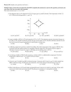


© Copyright 2026