
Jïrl'hz'lrEHamen'
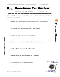
Oct 3, 1933.
'
l ,929,1 12
A. E. HANSEN
'
ELEvAToR FÓR TRUCKS
,Filed Nov. 24. 1931
-
3 sheè'ts-sneet
1 -`
Nm
w w»
\
nä
Il .
n
i
ä
.
n
n
.
à
'_
3mm i
ê‘ìw Jïrl‘hz'lrEHamen'
fA
¿M Ä.
_ oct. 3, 1933.
A. E. HANSEN
ELEVATOR FOR TRUCKS
Filed NOV. 24. 1931
5 7'
‘ 55'
lf2
3
90A
‘l
yL__90
ì
V’
'î
5
(22
Y
? I
n
n*
l*
22
\
l
âme/nto@
.Hr?hUrLHanœn
A
4
@wf/„Wal
y ~
1,929,112
Patented Oct. 3,- 1933'
Í UNITED lSTATES PATENT OFFICE
1,929,112
ELEVATOR FOR TRUCKS
Arthur E. Hansen, Seattle, Wash., ‘as'signor to
Young Iron'Works, Seattle, Wash., a corpora
tion of Washington
Application November 24, 1931 `
Serial No. 577,042
12 claims.
wi.' 214-17) '
My invention relates in general to trucks, and used for other purposes-_for instance, as a dumpA
more part‘cularly to a device for elevating heavy
truck.
-
It is a further object to provide an elevating
truck,---that is, the bottom of the truck body-to platform for use in such a connection, the eiïec
tive area of which may be increased at will.
5 that level.
packages from a level ~ below the bed of the
With present-day trucks, largely equipped with
_
The above stated objects are not exclusive of
pneumatic tires in order that they may travel at others, and such other objects may be ascertained
good speed, it becomes necessary to place the body as this specification progresses, and from a study
.
of the truck well above the ground. It is diffi of the drawings.
My invention comprises the novel parts and the 05
cult for workmen to raise heavy packages-for
instance, large barrels of ilour, bales of cotton, novel combination and arrangement thereof, as
or shipping cases-_upon such trucks, and consid shown in the accompanying drawings, described
erable time and effort is required in accomplish in the speciñcation, and as will be more particu
ing that end. Workmen object to using such larly pointed out by the claims which terminate
`
'
‘
70
15 trucks, with the result that other equipment is the same.
In the accompanying drawings I have Shown l
used if available, with consequent~ loss of eili
ciency, time, and investment.
-
my invention embodied in forms which are now -
It is an object of my invention to provide a preferred by me.
device, preferably built into the truck or sup
Figure 1 is a side elevation of the rear end
20 ported upon its chassis or beneath the body, by of a truck, illustrating my elevating device ass-o
75
means of which such loads may be lifted, pref ciated therewith.
Figure 2 is a rear view of the truck and elevat
erably by power means, from any lower level
for instance, the ground level-to a level' with the ing device, showing the elevator platform up
bottom of the truck body, so that the boxes need raised in the position of an end gate.
Figure 3 is a view similar .to Figure 2, showing 80
25 only be rolled or trucked upon the elevating plat- _
form, to be elevated in place upon the platform to the elevator platform in its lowered position.
Figure 4 is a- longitudinal vertical section
a level with the truck body, and then rolled or
hand- trucked into position on the truck body. through the elevator platform, shown with the
By 'such means a single workman may load a extension platform extended, the view being sub
30 large number of heavy packages in a short space stantially along the lineA 4-4-oi Figure 5, and 85
of time. As a result of a test, a single workman Figure 5 is a transverse vertical section substan
loaded sixteen barrels of oil, each weighing 675 tially on the line 5-5 of Figure 4.
Figure 6 is a side elevation of the control handle,
pounds, in twenty minutes,'a total considerably
and the indicating means associated therewith.
Figure '7 is a longitudinal vertical section
plish the result indicated by means of simple ap- I through the rear end of a truck, illustrating a
paratus, preferably one which is adapted to the slightly modified form of my invention, and Fig
employment of a hydraulic power or hoist unit, ure 8 is a rear end view of the same, correspond
whereby the same may be easily and suitably ing substantially to Figure 3.
40 controlled at all stages oi' the operation,- and may
The invention is capable of employment in 95
automatically be stopped at the two extreme po connection with various types of trucks, and I
sitions by means now commonly available.
have illustrated a conventional truck chassis 9
It is a further object so to design the elevating supported upon and driven by the rear wheels
mechanism that there will be no undue peak oi.' 90, and carrying a body 91 supported upon cross
10o
45 stress during the elevating operation, no passing
92. Such a body may have the sides 93,
through a dead center, and whereby there will holstersy
'be no tendency for parts to sag and to drop the the end being preferably left open.
in excess of five tons.
'
It is a further object of my invention to accom
load.
-
Supported beneath the body 9l-for instance,
It is a further object to devise an elevating upon brackets 20~bolted or riveted to the real'>
50 platform for use in such a connection which is end of the chassis 9-is a lifting arm or arms 2. 105
, so constructed and mounted that it may- also be
The number employed is largely immaterial,
employed as an end gate for the truck body; an though in order to balance the stresses it is pref
associated object is to devise mechanism capable erable that two be employed, one at each side.
-oi’ use as an elevator andas an end gate, with However, since the two sides are identical, a de
55 out detracting from the ability of the truck to be scription of one side alone will sumce.
Simi- lli)
2-.
Í
.
1,929,112
larly, each arm may be furcated, as illustrated, to lower it, or to hold it immovable in any given
to distribute the lifting stresses.
l
position. This control handle may be located in
>At its forward end this lifting arm is pivotally a convenient position .on the truck body, for
supported, being secured, for instance, upon thev instance, adjacent its rear end, where the oper
transverse shaft 21. The rear ends of these arms ator can watch the load as it is being elevated. 80
2 are pivotally connected, for example, through - In -order to avoid overtaxing the springs and
the medium of the transverse pin 22, to a plat to relieve any detrimental strain on the chassis
form member 1. I prefer, for reasons that will during the operation of the elevator, when heavy
appear hereafter, that the connection be not a loads are concentrated at its rear end, it may be
10 direct one, but rather that the platform 1 be desirable to employ a leg 7 which may be pivot
85
pivotally supported upon the cross rod 22, which
ally supported from the chassis to swing down
rod is supported by the swinging end of the into a position where it will nearly or quite con
‘
tact with the ground, thereby to support a por
Preferably there is also pivotally supported tion of the load, and which may be swung up
15 upon the cross rod 22 an upright bar 3. The plat ward and held, for instance, in clips '11, when the 90
form 1, distant from the pivot 22, may be braced truck is travelling.
and supported from the upper end of the up
It may be desirable to load large bulky packages
right bar 3 in any suitable manner, for instance, which require more area than is available in the
by the limit chain 31.
_
'
height of the average end gate, and the platform
In order to maintain this bar- 3 upright, and 1 therefore may have associated with it an ex
20
_to guide the bar 3 and the platform -1 for move tension platform 10, which is slidably mounted
ment through positions always parallel to any to be extended laterally. Downwardly turned
arm 2.
given initial position, I employ an arm 4 which flanges on the extension platform 10 may rest
is pivoted at 4l immediately above the shaft 21 upon ledges 12 at the sides of the elevating plat
and at 42 upon the bar 3. _ The spacing between
the axes at 21 and 41 is substantially the same
as the spacing between the axes 22 and 42,»where
by the arms 2 and 4 constitute in effect a pair
„ of parallel links. The pivot at 41 may be upon
so a transverse member 44 which is supported from
the chassis 9'.
The pivot 22 may occupy a position substan
tially at the end of the truck body, so that the
platform 1 may swing as an ordinary tail gate.
35 The chain 31 limits its downward swinging to a
form 1.
A stiifening member 13 forms an in
ward stop for the extension platform l0, and
brackets 14, engageable by a downwardly turned
100
flange l5 upon the extension platform serve as
outward limiting stops. The ribs 11, incidental
ly, serve to stiifen not only the extension platform 105
10 but the elevating platform 1. Either the ele
vating platform 1, if the extension platform is
not used, or the latter, may be provided with an
inclined apron 16 facilitating the wheeling of
hand trucks or dollies thereupon.
110
horizontal position, and permits it to'swing up
Figures 7 and 8'illustrate a modified form, one
ward into a substantially vertical position, where adapted for light work and for hand operation.
it will be suitably secured in a manner common The circular segmental member 5' herein takes
l - A in connection
with tail gates.
'
Provision may be
the form of a gear, and meshing therewith is a
40 made, if desired, for letting go the chain 31 gear pinion 51’ operable by a crank handle 53'. 115
altogether, so that the end gate may swing com
pletely down.
A dog 56’ engageable with a ratchet wheel 57’
serves to hold the elevating mechanism at any
The Ámanner of swinging the lifting arm 2 and desired point. Any suitable brake mechanism
its parallel link, thel arm 4, is largely immaterial. (not shown) may be used to retard downward
However, it makes for simplification to employ movement of the platform.
a circular segmental member 5 which may' be
In this form the circular segmental member 5'
made up of two plates spaced by suitable spread is- formed integral with the lifting arm 2', and
ers and bolts, illustrated at 50, whereby there is the construction is thereby simpliñed. The ex
formed a substantially circular segmental groove tension platform 10’ is rudimentary only, since it
50 to receive a ñexible member such as the chain will not ordinarily be desirable to carry large 125
or cable 51.
The member 5 is secured upon the
>shaft 21, and will be shaped to avoid contact with
parts of the chassis and like members. The
ist
cable 51 is connected to the piston rod 52'of
a hydraulic power unit, generallyindicated at
53.
This is mounted upon the chassis or be
neath the body, forV instance, by the pivotal
mounting at 54 (see Figure 1), and there is nor
mally incorporated in such a unit a pump 55
controlled by a valve 56. Suitable power means
75
and bulky loads on light equipment such as is
illustrated in connection with this form. '
'
It is believed that the operation of the device
is obvious. The platform l may be dropped to
any desired position, for instance, to the ground 13")
level, and while in this position may have placed
upon it the load which is to be elevated to the
truck body 91. Now the power mechanism is
brought into play, causing the lifting arm 2 to
rise, and it will be observed that it rises sub 135
stantially from a point where the rod 22 is 38°
below the shaft 21 to a point where it is 38° above
it. Such angles, it will be understood, are illus
trative only. .The parallel link 4 maintains the
bar 3 upright and the platform 1, braced there 140
to drive the pump 55', from the truck’s motor,
are indicated generally lat 57.
In order to control the position of the valve
56, and thereby thedirection of movement of
the piston rod 42, the valve lever 58 maybe con
nected to a suitable control lever 6 carried upon from, horizontal, and because the pivots of these
the shaft 60, upon which shaft is secured a lever parallel links are disposed one above the other,
61 connected by a link 62 to the valve lever 58. the four pivots never come into alignment, and
Movement of the control lever 6 over` a quadrant consequently there is no position where the load
63 (see Figure 6) gives corresponding movement passes dead center, nor increases considerably 14o
to the valve lever 58, and the quadrant may be with respect to other. positions. When the load
marked as is indicated at Figure 6 with suitable has reached the level of the truck body, the plat
indications to designate positions in which the form 1 abuts the rear end of the truck, and the
pump will cause movement of the power mecha load may be pushed, rolled, or wheeled off the
nism in a direction to elevate the platform 1, platform and onto the truck body.
150
3.
1,929,119
If at any time the operator desires to hold the
platform 1 at a position it has attained, whether
the lowered position, the upper position, or any
intermediate position, he may accomplish this by
suitably positioning the control handle 6, as has
been explained. By suitable arrangement of the
power hook-up and the automatic stop or by
pass usually incorporated in hoist pumps, the
platform will be made to stop automatically in
10 the two extreme positions.
When the load is finally in place, the plat
form 1 being in its upper position, may be moved
to its upraised position, where it stands verti
cally, and being secured in this position it acts
said links'and to raise the platform from a hori
zontal position, below the pivots beneath the
body, through parallel positions to an upper posi
tion above such pivots, and substantially level
15 as a tail gate to prevent loss of the load.
a point spaced above said shaft, and pìvotally
connected by its other end to said platform ata
point spaced above the pivot connection thereto
Inci
with the body.
Í
5. In combination with a truck body, an ele
vator platform, a lifting arm pivotally connected
by one ,end to said platform, a transverse rock
shaft to which the other end of said' arm is se
cured, a circular segmental member likewise
secured to said shaft, means to apply a force act
ing tangentially lto said segmental member to
rock said shaft, thereby to lift said platform, and
a second arm pìvotally supported by one end at
dentally, being thus upraised, there is no possi
bility of the extension platform 10 being ex
tended, and the apron 16, if provided .on the of the flrst arm a distance equal to the spacing of
extension platform, may be sufficiently with their opposite ends.
.
20 drawn that it will not be subject to damage.
6. In combination with a truck body- and wheels 95
If theuoperator wishes to drop the tailgate out supporting the same a given distance above the `
of the way he lets go the chains 31, and accom ground level, and overhanging the wheels, an ele
plishes his end without disturbing the power vator platform, two parallel links, each having.
onev end pìvotally mounted at points spaced one
What I claim as my invention is:
above the other, and beneath the body, the other
l. In combination with a truck body, an end of said parallel links being connected to the
mechanism.
25
elevator platform, an upright bar to the lower
end of which said platform is pìvotally connected,
and means extending between the bar and plat
30 form to limit the latter’s downward swing to sub
stantially a horizontal position, two parallel links
of equal length each having one end pìvotally
mounted at points beneath the' body, spaced one
above the other, the other end of said links be
35 ing pìvotally connected with the upright bar
at points spaced substantially the same as the
spacing of the first points, and likewise disposed
elevator platform at points likewise spaced one
above the other for movement of the platform,
said pivots being so located, with respect to the
ground level and body level, -that the platform
is guided for movement from a position at ground
105
level and outwardly of the body’s overhang, up-`
wardly through horizontal positions always `outward of the body’s overhang, to the body level, in
prolongation of the body.
_
110
7. In combination with a truck body and
wheels supporting the same a given distance
one above the other, and means to swing said above the ground level, and overhanging the
parallel links to raise the bar and platform, the wheels, an elevator platform, a lifting arm piv
40 latter through horizontal positions, from the
45
50
(30l
75
y
otally supported beneath the body and at a level 115
ground level to the level of and abutting the midway between ground level and the body level,
end of the body.
.
a parallel link pìvotally supported at a point
2. In combination with a truck body, an ele
vator platform, an upright bar to the lower end spaced above the pivot of thelifting arm, the
of which said platform is pìvotally connected, swinging ends of said arm and said link being piv
collapsible brace means connecting the upper end otally_ connected to the elevator platform at 120
of the bar and the platform outwardly of such points likewise spaced one above the> other, and
not lower than the plane of the platform itself,
pivot to limit the downward movement of the and
means to raise the platform through a path
platform, whereby the platform may swing rela
tive to the bar between horizontal and vertical prescribed by the lifting arm and link, from a
positions, two parallel links each pìvotally sup position at ground level and outside the overhang 125
ported at one end at points spaced beneath the of the body, through horizontal positions to .the
_
body, and each pìvotally connected at its other body level, in prolongation of the body.
8. In combination with a truck body, two equal
end to said bar at spaced points,l thereby to re
strain the bar for movement through positions parallel links pivoted each by one end therebe
always parallel to an initial position, and means neath at points spaced one above the other and 130
exte?dingrearwardly, one of said links having
to elevate said bar.
3. In combination with a truck body, an up~ an arm projectingforwardly of its pivot, an ele
right bar, parallel links pìvotally connected re vator platform, the rear ends of the parallel links
spectively to points spaced along said bar and to being pivoted to said platform at points spaced
similarly spaced points beneath the body, an one above another, the lower point being substan 135
elevator platform swingably supported from said tially in the plane of the platform, and means dis
bar along an axis coinciding with the connection posed beneath the truck body to apply a force to
thereto of one of said links, means extending the said forwardly projecting arm to swing Isaid
between the bar and platform to limit the latter’s links, thereby to- raise the platform from a hori
downward swing _to a substantially horizontal zontal position, substantially at ground level, 140
position, and means to raise said platform from a through parallel positions to an upper position,
substantially level with the body.
lowered position to the body level.
9. In combination with a truck body, two equal
4. In combination with a truck body, two equal
parallel links pivoted each by one end therebe parallel links pivoted each by one end therebe
neath at points spaced one above the other and neath at points spaced one above the other and 145
extending rearwardly, an elevator platform to extending rearwardly, an elevator platform,
which the rear ends of the parallel links are piv means extending wholly above the level of the
oted at spaced points one of which is disposed platform to support the same, the rear ends of
above the platform, and means to apply a force said parallel links being pivoted to the platform
to the forward end of a'link, thereby to swing supporting >means at points spaced one above 150
1,929,112
another, and means to swing said links, thereby to stantially midway between the ground level and
raise the platform from a horizontal position, the body level, and plvotally connected by its
substantially at ground level, through parallel other end- to the platform, means to swing said
positions to an upper position substantially level
with the body, the pivot points of the parallel
links beneath the body being so located, with re
spect to the ground and body levels, that in move
ment between such levels the forward edge of the
arm to raise the platform to an upraised position
at the body level, and a link pivoted above the
lifting arm at the platform, and likewise plvotally
supported above the first-mentioned pivot of the
lifting arm, to maintain the platform substan
platform is never forward of the rear end of the tially level throughout its raising.
10
body.
12. In combination with a truck body, an ele
10. In combination with a truck body and vator platform having associated with it a sup-v
85
wheels, two parallel links each having one end porting member extending upward at its forward
plvotally mounted at points beneath the body edge,> a lifting arm pivotally supported beneath
-spaced one above the other, and one having an the truck substantially midway between the level
15 arm extending forward of such pivot, an elevator of the body and the normal ground level, and 90
platform to which the >other ends of said parallel engaged with saidrplatforg/i, a link pivoted be
links are plvotally connected at points likewise
spaced one above the other, and neither of which
is lower than the general plane of the platform,
20 whereby the platform may rest upon the ground
at the normal level whereon the wheels rest, and
means disposedbeneath the truck body to apply a
force to said forwardly extending arm to raise
the platform through a path prescribed by said
25
neath the truck body and above the pivot of the
lifting arm, and extending parallel to the lifting
arm to engage said upwardly extending support
ing member, at a point which is above the point 95
of engagement of the lifting arm, and at nearly
the level of the pivot of the lifting arm when
the platform is lowered to normal ground'ïlevel,
and means to swing said lifting arm to move the
platform from a lowered position through hori 100
11. In combination with a truck body, an ele zontal positions to an upper position, at body level
vator platform, a lifting arm pivotally supported and in rearward prolongation thereof.
by one end at a point b‘eneath the body and sub
ARTHUR E. HANSEN.
parallel links.
'
.
105
35
il@
115
E20
50
l25
5.5
130
60
135
65
i140
70
145
75
150


© Copyright 2026