
UPS and Critical Power Solutions
CATALOGUE
UPS and Critical Power Solutions
2013
Choose the right solution
MODULYS Green Power
Green Power 2.0
Smart PowerPort
Energy Storage
Communication
and Connectivity
Commissioning, Inspection
and Maintenance
2
Catalogue 2013
Meeting critical application requirements
in industrial environments
DELPHYS MP elite
DELPHYS MX
MASTERYS IP+
CPSS Emergency
STATYS
IT SWITCH
Rectifiers
Static Transfer Systems
(STS)
Uninterruptible Power Supply
(UPS)
Guaranteeing the availability of applications, providing energy
cost-savings and reducing your carbon footprint
SHARYS IP
Flywheel
BHC Universal
BHC Interactive
BHC Universal
Contents
Socomec Group ..................................................................................................... p.4
Guaranteeing the power supply quality
to critical loads
MASTERYS BC
DELPHYS BC
Guaranteeing
the availability
of applications,
providing energy
cost-savings and
reducing your
carbon footprint
MODULYS Green Power .......................................... p.8
Green Power 2.0 10-120 .......................................... p.12
Green Power 2.0 160-500 ........................................ p.14
Smart PowerPort .................................................... p.16
STATYS ................................................................... p.18
IT SWITCH ............................................................. p.20
BHC Universal and BHC Interactive ....................... p.22
Flywheel ................................................................. p.24
7
Meeting critical
application
requirements
in industrial
environments
DELPHYS MP elite ................................................. p.28
DELPHYS MX ......................................................... p.30
MASTERYS IP+ ....................................................... p.32
SHARYS IP ............................................................. p.34
CPSS Emergency .................................................... p.38
27
Guaranteeing
the power supply
quality to critical
loads
MASTERYS BC ........................................................ p.42
DELPHYS BC .......................................................... p.42
39
Complementary
solutions
NET VISON
VIRTUAL JNC
REMOTE VIEW
MODBUS TCP
DRY CONTACT
SNMP/WEB
MASTERYS Battery Cabinets ................................. p.46
ATRYS .................................................................... p.48
Solutions in container or shelter ............................ p.50
43
Communication
and connectivity
Communication software ...................................... p.54
Communication interfaces ..................................... p.58
53
CIM maintenance contracts
24/7 real-time monitoring service
CIM Thermo
CIM Rent
Commissioning,
Inspection and
Maintenance
59
CIM maintenance contracts ................................... p.64
24/7 real-time monitoring service .......................... p.65
CIM Thermo ........................................................... p.66
CIM Rent ................................................................ p.68
Catalogue 2013
3
SOCOMEC: an independent manufacturer
the benefit of a specialist
CORPO 308 A
Founded in 1922, SOCOMEC
is an industrial group with
a workforce of 3200 people.
Our core business - the availability,
control and safety of low voltage
electrical networks with increased
focus on our customers’ power
performance.
The culture of independence
A flexible manufacturing structure
Responsible growth
The SOCOMEC Group’s independence
ensures control over its own decision-making,
respecting the values advocated by its
own family shareholders and shared by its
employees.
With around 30 subsidiaries located on all five
continents, SOCOMEC pursues international
development by targeting industrial and
service applications where the quality of its
expertise makes all the difference.
Backed by two European centres of
excellence (France and Italy), the Group also
benefits from competitive production sites
such as Tunisia and locations in the major
emerging markets (India and China).
These sites have all implemented a system
of continuous improvement based on Lean
Management principles, and are therefore in a
position to provide high levels of quality, and
meet the deadlines and cost requirements
expected by customers.
As a Group which is open to all cultures
and firmly committed to human values,
SOCOMEC promotes employee initiative
and commitment. Working relationships are
based on the idea of partnerships and respect
for shared ethics. Through the company’s
commitment to achieving harmonious, lasting
development, SOCOMEC fully embraces
its responsibilities not only towards its
shareholders, employees, customers and
partners, but also towards society as a whole
and its environment.
SOCOMEC has been a signatory to the
Global Compact since 2003.
The spirit of innovation
As undisputed specialists in UPS systems,
mains supply changeover, power conversion
and measurement, SOCOMEC dedicates
nearly 10% of its turnover to R&D. As a result
the Group can achieve its ambition of always
being one technological step ahead.
The vision of a specialist
As a manufacturer with complete control
over its technological processes, SOCOMEC
is quite unlike the more general providers.
The Group is constantly improving its fields
of expertise in order to offer its clients
increasingly customized, appropriate solutions.
4
Catalogue 2013
The focus on service
Our manufacturer’s expertise naturally
extends to a complete range of services
designed to facilitate the research,
implementation and operation of our
solutions. Our service teams have built their
reputation on reassuring guidance, flexible
skills and reactivity.
For a high quality power supply
innovative power solutions
A key requirement
High quality energy supply at any moment
is vital in many fields such as IT, industry
and infrastructure applications. It is even
mission-critical for many medical applications.
SOCOMEC UPS has over 40 years of
experience at your disposal.
Product solutions that meet
requirements
Underpinned by significant R&D resources,
our product offer continually evolves as a
consequence of our contact with customers.
To ensure the highest availability, we provide
the latest UPS technology combined either
with traditional batteries or with other
innovative energy storage systems.
Our solutions have the approval of some
of the most stringently demanding users:
Telecom companies worldwide, Ministries of
Defence, nuclear industry operators...
Recognised expertise
Prestigious accolades have been presented
in recognition of the company’s ability to
meet the needs and product demands of its
customers. Among others:
• customer Service Excellence (2004),
• product Innovation (2006),
• best Practice Award for “European Energy & Power Systems Product Line Strategy”
(2009),
• European UPS new product
innovation award (2011).
GAMME 008 W
The SOCOMEC UPS product
range covers all needs for a high
quality, faultless electrical power
supply.
Our UPS, as well as our secure
power supplies, static transfer
systems, harmonic equalizers,
rectifiers and DC/AC and AC/DC
converters, comprise the most
complete ranges in the world and
cover a very wide range of
applications for every sector
of the market.
Always focused on customer
needs
Our sales and after-sales network means
we are always there for you. Our partnercustomers recognise the quality of our
products, availability and flexibility in meeting
requirements and commitment.
SOCOMEC joined the United Nations
“Global Compact” in 2003 to tackle the social
and environmental challenge of globalization.
Continuing innovation
The facts speak for themselves:
• first French manufacturer to offer static
power supplies (1968),
• first UPS designed with PWM technology
(1980),
• first UPS range in the world using IGBT
technology (1990),
• first modular, scalable and redundant UPS
system (2000),
• first to integrate hybrid components (2001),
• first 200 kVA UPS with IGBT rectifier (2003),
• new battery charging design (2004),
• dynamic energy storage system (flywheel)
(2006),
• first UPS with 96% efficiency in true online
double conversion mode (2007),
• most compact STS 19” rack hot-swappable
(2009),
• most compact 900 kVA UPS (2010),
• first complete UPS range (10-2400 kVA)
with 3-level technology, 96% efficiency and
power factor 1 (2012).
ISO 14001 This international standard
recognizes SOCOMEC’s determination on
pursuing its commitment to preserve the
environment.
The Green GridTM is an organization committed
to improving the resource efficiency of data
centres and business computing ecosystems.
As Endorser on the European Code of
Conduct for Data Centres, SOCOMEC
UPS is committed to implementing energy
efficient solutions in new data centres whilst
respecting the life cycle, cost-effectiveness
and the performance availability of the system.
Catalogue 2013
5
Guaranteeing the availability of
applications, providing energy
cost-savings and reducing your
carbon footprint.
Optimized solutions for
virtualized data centers
MODULYS Green Power
Improved output of
critical applications
Green Power 2.0
Three-phase UPS
20 to 360 kVA
p.8
Three-phase UPS
10 to 120 kVA
p.12
160 to 500 kVA
p.14
Rapid implementation of
‘plug & play’ power supply
solution
Smart PowerPort
Rapid implementation of
‘high-availability’ architecture
STATYS
UPS power infrastructure in container
100 kW to 2.4 MW
p.16
Single and three-phase STS
32 to 4000 A
p.18
IT SWITCH
Single-phase electronic transfer systems
16 to 20 A
p.20
Longer battery service life
BHC Universal and BHC Interactive
Battery Health Check
p.22
Implementation of a dynamic
energy storage solution
Flywheel
Dynamic Energy Storage Systems
80 to 900 kVA
p.24
Catalogue 2013
7
MODULYS Green Power
Three-phase UPS
from 20 to 360 kVA
a modular, scalable UPS solution for the latest virtual data centres
The solution for
> Virtualised data centres
> IT Networks / Infrastructures
> Mission critical applications
Certifications
MODULYS Green Power efficiency
is verified by TÜV SÜD.
GREEN 039 A
MODULYS Green Power
is certified by NEMKO with
regard to product safety
(EN 62040-1).
Advantages
Designed for continual change
• Dynamic power infrastructure able to closely
align power capacity required by rapidly
growing ICT businesses.
• Fully modular architecture based on power
and battery modules.
• Less complexity for system deployment
with repeatable hot pluggable and hot swap
modules.
Change management without
affecting availability
• No risk of downtime to upgrade power
capacity or battery capacity.
• Superior availability during normal operation
and even under maintenance by using
redundant and independent components.
• Self-diagnosis both at module and system
levels, remote monitoring and alert capability
to manage operational parameters in
real time and decide when an upgrade is
necessary.
8
Catalogue 2013
Performance optimisation
while changing
• Power granularity to deploy the right number
of modules and get all the necessary power
protection at the right time.
• Extensive upgradability to maintain
maximum power quality and manage costs
simultaneously.
• Reduced complexity, enhanced
serviceability, and responsiveness in the
case of module failure for a very low MTTR
(Mean Time To Repair).
Energy savings and granularity
of investment
• Modularity and energy efficiency design
meet the new ROI (Return Of Investment)
metrics perfectly, based on TCO that
incorporates initial investment, full lifecycle
infrastructures and facility costs.
• Energy efficiency means reduced energy
losses, electricity operation costs, heat
dissipation, cooling resources required and
operational costs, resulting in significantly
lower energy bills.
• Modularity minimises capital and expenses:
no prior expenditure required for spare
capacity or additional installation costs for
future extensions.
MODULYS Green Power
from 20 to 360 kVA
Three-phase UPS
Configurations
Module installation
MODU
LYS
Green
Power
1
MODU
LYS
Green
Power
MODU
LYS
Green
GREEN 091 A
Power
MODULYS
Green Power
Modular
battery cabinet
MODULYS
Green Power
Coupling
cabinet
MODULYS
Green Power
Modular
battery cabinets
Modular
battery cabinet
2
Modular
battery cabinet
Technical data
3
MODULYS Green Power
4
5
6
7
8
9 10 11 12 13 14 15 16 17 18
80 100 120 140 160 180 200 220 240 260 280 300 320 340 360
72 90 108 126 144 162 180 198 216 234 252 270 288 306 324
3/3
N+x
Number of modules
1
2
3
Sn [kVA] - module
20 40 60
Pn [kW] - module(3)
18 36 54
Input/output
Redundant configuration
INPUT
400 V
Rated voltage
-25 % + 20 % (up to -50 % at 70 % Pn)
Voltage tolerance
50/60 Hz
Rated frequency
± 10%
Frequency tolerance
0.99 / < 3%
Power factor / THDI(1)
OUTPUT
Rated voltage
400 V (380/415 configurable)
Voltage tolerance
± 1%
Rated frequency
50/60 Hz (selectable)
Frequency tolerance
± 0.05% (on mains power failure)
Voltage distortion
< 1 %
125% for 10 minutes, 150% for 1 minute
Overload(2)
Crest factor
3:1
BYPASS
Rated voltage
400 V (380/415 configurable)
Voltage tolerance
± 15% (configurable from 8% to 15%)
Rated frequency
50/60 Hz (selectable)
Frequency tolerance
± 1 Hz (configurable from 0.5 to 5 Hz)
MODULE
Battery charging current
1.2 - 5 A
Efficiency - On-line mode
up to 96 %
Efficiency - Eco Mode
up to 98 %
Weight
30 kg
ENVIRONMENT
Operating ambient
from 0 °C up to +40 °C (from 15 °C to 25 °C for maximum battery life)
temperature
Relative humidity
0 % - 95 % without condensation
Maximum altitude
1000 m without derating (max. 3000 m)
Acoustic level at 1 m
60-66 dBA
(ISO 3746)
Required cooling capacity
440 ÷ 8960 m3/h
Dissipated power
1000 ÷ 18140 W
Dissipated power
3400 ÷ 61900 BTU/h
UPS CABINET
Dimensions W x D x H
520 x 975 x 1695 mm
520 x 975 x 1695 mm
520 x 975 x 1695 mm
Weight (empty cabinet)
200 kg
200 kg
200 kg
Degree of protection
IP20
Colours
cabinet: RAL 7012, front bottom base: RAL 7016
STANDARDS
Safety
EN 62040-1 (NEMKO certified), EN 60950-1
EMC
EN 62040-2
Performance
EN 62040-3 [VFI-SS-111]
Product declaration
CE
4
Standard electrical features
• Dual input mains.
• Internal maintanance bypass.
• Parallel kit.
• Battery charger.
• External modular battery cabinet.
• Long life batteries.
Electrical options
• External maintanance bypass up to
360 kVA.
• Relay card.
Standard communication
features
• Embedded LAN connection: professional
WEB/SNMP interface for UPS monitoring
and shutdown management of several
operating systems.
• Dry-contact interface.
Communication options
• MODBUS/JBUS RTU
Battery cabinets - Technical data
MODULAR BATTERY CABINET
DIMENSIONS AND WEIGHT
Dimensions W x D x H
600 x 900 x 1695 mm
Weight (empty cabinet)
161 kg
Weight (battery string)
121 kg
HIGH CAPACITY BATTERY CABINET
Dimensions W x D x H
600 x 900 x 1695 mm
Weight
599 kg
(1) For source THDV < 2 % and nominal load. - (2) From inverter. - (3) @ 25 °C.
Catalogue 2013
9
MODULYS Green Power
from 20 to 360 kVA
Three-phase UPS
Totally modular for the best modular UPS system
Power scalability up to 360 kVA
MODULYS GREEN POWER suits perfectly,
either with unscheduled site upgrades or
upgrading in successive steps, thanks to its
modularity.
1. Multilangua
Multilanguage LCD graphic
mimic pane
panel
1. Bays for pl
plug-in hot swap
1.
4.
5.
6.
7.
power mod
modules
LED showi
showing power
module sta
status
INPUT swit
switch
Manual BY
BY-PASS switch
AUX MAIN
MAINS switch
OUTPUT switch
s
MODU
LYS
Green
Power
VERTICAL
MODULARITY
System 1
from 20 to
VERTICAL
120 kVA
MODULARITY
System 2
from 140 to VERTICAL
MODULARITY
240 kVA
System 3
from 260 to
360 kVA
MODU
LYS
Green
Power
MODU
LYS
Green
Power
GREEN 035 A
HORIZONTAL
MODULARITY
System 1 + System 2
+ System 3
4
6
5
7
Availability
• Redundant N+1 architecture based on
parallelable plug-in power modules providing
full power supply to load even if a module fails.
• No single point of failure thanks to built-in
redundant system design: redundant power
supply, charger, etc.
• Reduced MTTR: power system remains
in online mode and a module can be easily
replaced or added in a few minutes without
compromising load protection.
• Self-configuration ensures agility while
changing, and maximum availability
during maintenance operations (load not
transferred to by-pass mode).
• Built-in fan speed control and individual fan
efficiency check.
• Dual input feed (Mains and Aux Mains)
guarantees maximum availability of
emergency bypass line.
10
Catalogue 2013
Flexibility
• MODULYS GREEN POWER vertical and
horizontal modularity easily and quickly
supports the wide range of evolving load
requirements.
• Repeatable and standardised scalable
architecture based on real hot pluggable
power modules.
• Vertical modularity for power scalability
up to 120 kVA by simply plugging a power
module into the system.
• Horizontal modularity for scalability up
to 360 kVA by coupling three modular
systems.
• Power granularity to meet detailed power
on demand for incremental steps of
20 kVA.
Total Cost of Ownership (TCO)
• Modularity and power granularity make it
possible to invest only for the functionality
required in the short-term, and to plug in
new capacity or functionality when the time
is right.
• Savings in operational costs and energy
bills by combining the maximum level of
protection (true online double conversion)
with verified 96 % efficiency.
• Vertical modularity maintains a small
footprint while system power capacity
increases.
• Fast deployment thanks to the vertical
modular architecture. Fast power increase
without any new electrical work.
• High efficiency minimises heating and
cooling requirements, reduces air
conditioning investments, and cuts related
energy bills.
GREEN 092 A GB
2
1
3
MODULYS Green Power
from 20 to 360 kVA
Three-phase UPS
Totally modular for the best modular battery solution
1
2
STANDARD
ST
TANDARD BA
BATTERIES
ATTERIE
TT
S
LONG
G
LIFE
Scalable battery solutions
• Vertical modularity
Maintains equivalent autonomy while power
increases with the modular battery cabinet.
Autonomy range: from 10 to 60 minutes.
MODU
MODU
LYS
LYS
Green
Power
Green
GREEN 093 A GB
Power
3 power
modules
5 power
modules
3 battery
modules
5 battery
modules
• Horizontal modularity
Provides very high and scalable autonomy
with the high capacity battery cabinet.
Autonomy range: up to 120 minutes.
MODU
LYS
Green
GREEN 054 A
Power
MODU
LYS
Green
Power
GREEN 094 A GB
3 power
modules
1 battery
cabinet
3
1. Six bays for battery hosting
2. Four hot swap battery packs for
5 power
modules
2 battery
cabinets
each string
3. Battery protection for each string
Availability
• Battery system based on independent
strings connected in parallel to maximise
system availability.
• Individual battery string protection for safe
running, installation and maintenance of the
battery system, and to ensure continuous
back-up protection.
• Long-life battery provided as standard, to
increase quality and reliability.
• On-going maintenance of each battery
string is performed from the front, with
MTTR reduction as result.
• Hot swap battery pack solution allows
back-up time increases according to power
requirements, without switching off the
battery cabinet.
Flexibility
• Scalable battery strings (up to 6) to
maintain equivalent autonomy while power
increases.
• Preset for on-site fast autonomy
extension without any electrical system
modification.
• Battery scalability based on unique battery
packs (up to 24).
• Powerful battery charger integrated
within each power module to enable long
autonomy (up to 120 minutes).
Total Cost of Ownership (TCO)
• Standard long-life battery technology
improves system reliability, maximises
return on investment and reduces
maintenance costs associated with
expected battery life.
• A standard temperature sensor optimises
the battery recharging parameters according
to environment temperature to extend
battery life and investment.
• Vertical modularity in a small footprint
battery cabinet allows an increase in
back-up without occupying further space
on the site.
• Shared battery bus architecture minimises
battery investment without compromising
availability.
Catalogue 2013
11
Green Power 2.0
Three-phase UPS
MASTERYS GP from 10 to 120 kVA/kW
ultra high energy efficiency and maximum power availability
The solution for
> Data centres
> Telecommunications
> Service sector
> IT-Networks / Infrastructures
Certifications
GAMME 125 B
GAMME 202 C
The Green Power 2.0 series
is certified by TÜV SÜD with
regard to product safety
(EN 62040-1).
Advantages
Energy saving + Full rated power = reduced TCO
Energy Saving: high efficiency
without compromise
• Offers the highest efficiency in the market
using VFI – Double Conversion Mode, the
only UPS working-mode that assures total
load protection against all mains quality
problems.
• Ultra high efficiency output independently
tested and verified by an international
certification organization in a wide range of
load and voltage operating conditions, to
have the value in the real site conditions.
• Ultra high efficiency in VFI mode is
provided by an innovative topology (3-Level
technology) that has been developed for all
the Green Power UPS ranges.
Full-rated power: kW=kVA
• No power downgrading when supplying the
latest generation of servers (leading or unity
power factor).
• Real full power, according to IEC 62040:
kW=kVA (unity power factor design) means
25% more active power available compared
to legacy UPS.
• Suitable also for leading power factor
loads down to 0.9 without apparent power
derating.
12
Catalogue 2013
Significant cost-saving (TCO)
• Maximum energy saving thanks to 96%
efficiency in true double conversion mode:
50% saving on energy losses compared
to legacy UPS gives significant savings in
energy bill.
• UPS “self-paying” with energy saving.
• Energy Saver mode for global efficiency
improvement on parallel systems.
• kW=kVA means maximum power available
with the same UPS rating: no overdesign
cost and therefore less €/kW.
• Upstream infrastructure cost optimization
(sources and distribution), thanks to high
performance IGBT rectifier.
• Battery configuration can be optimized,
thanks to a very wide DC range.
• Extended battery life and performance:
- long life battery,
- very wide input voltage and frequency
acceptance, without battery use.
• EBS (Expert Battery System) charging
management improves battery service life.
Better performance
than the EU Code of Conduct
on efficiency of AC UPS
Green Power 2.0
MASTERYS GP from 10 to 120 kVA/kW
Three-phase UPS
Standard electrical features
Electrical options
• Dual input mains.
• Internal maintanance bypass.
• Backfeed protection: detection circuit.
• EBS (Expert Battery System) for battery
management.
• Battery temperature sensor.
• External maintanance bypass.
• External battery cabinet.
• Additional battery chargers.
• Galvanic isolation transformer.
• Parallel kit.
• ACS synchronization system.
Standard communication
features
• User-friendly multilingual interface with color
graphic display.
• Commissioning wizard.
• 2 slots for communication options.
• MODBUS TCP.
• MODBUS/JBUS RTU.
• Embedded LAN interface (web pages,
email).
Technical data
Sn [kVA]
Pn [kW]
Input / output 3/1
Input / output 3/3
Parallel configuration
INPUT
Rated voltage
Voltage tolerance
Rated frequency
Power factor / THDI
OUTPUT
Rated voltage
10
10
•
•
15
15
•
•
20
20
•
•
30
30
•
MASTERYS GP
40
40
•
up to 6 units
60
60
•
80
80
•
100
100
•
120
120
•
400 V 3ph+N
240 V to 480 V(1)
50/60 Hz ± 10%
> 0.99 / < 2.5%
1ph + N: 230 V (can be configured 220/240 V)
3ph + N: 400 V (can be configured 380/415 V)
static load ±1 % dynamic load in accordance with VFI-SS-111
50/60 Hz
± 2% (configurable for GenSet compatibility)
Voltage tolerance
Rated frequency
Frequency tolerance
Total output voltage distortion < 1%
linear load
Total output voltage distortion < 3%
non-linear load
Overload
125% for 10 minutes, 150% for 1 minute (1)
Crest factor
3:1
BYPASS
Rated voltage
rated output voltage
Voltage tolerance
± 15% (configurable with from 10% to 20%)
Rated frequency
50/60 Hz
Frequency tolerance
± 2%
EFFICIENCY (TÜV SÜD verified)
Online mode @ 50 % of load
up to 96%
Online mode @ 75 % of load
up to 96%
Online mode @ 100 % of load
up to 96%
Eco Mode
up to 98%
ENVIRONMENT
Operating ambient temperature
from 0 °C up to +40(1) °C (from 15 °C to 25 °C for maximum battery life)
Relative humidity
0% - 95% without condensation
Maximum altitude
1000 m without derating (max. 3000 m)
Acoustic level at 1 m (ISO 3746)
< 52 dBA
< 55 dBA
< 60 dBA
< 65 dBA
UPS CABINET
W
444 mm
600 mm
700 mm
Dimensions
D
795 mm
800 mm
H
800 mm
1000 mm
1400 mm
1930 mm
Weight
190 kg
195 kg
315 kg 320 kg 180 kg 200 kg 380 kg 460 kg
Degree of protection
IP20
Colours
RAL 7012
STANDARDS
Safety
EN 62040-1 (TÜV SÜD certified), EN 60950-1
EMC
EN 62040-2
Performance
EN 62040-3 (VFI-SS-111)
Product declaration
CE
Communication options
• Remote mimic panel.
• Dry-contact interface.
• PROFIBUS.
• BACnet/IP interface.
• NET VISION: professional WEB/SNMP
interface for UPS monitoring and shutdown
management of several operating systems.
Remote monitoring service
• Remote mobile and web-based surveillance
service connected 24/7 to your local
Socomec Service Centre.
(1) Conditions apply.
Catalogue 2013
13
Green Power 2.0
Three-phase UPS
DELPHYS GP from 160 to 500 kVA/kW
ultra high energy efficiency and maximum power availability up to 4 MW
The solution for
> Data centres
> Telecommunications
> Service sector
> IT Networks / Infrastructures
Attestations
B U R E A U
VERITAS
Green Power 2.0 is attested
by Bureau Veritas
GAMME 305 A
Advantages
Energy saving + Full rated power = reduced TCO
Energy saving: high efficiency
without compromise
• Offers the highest efficiency in the market
using VFI – Double Conversion Mode, the
only UPS working-mode that assures total
load protection against all mains quality
problems.
• Ultra high efficiency output independently
tested and verified by an international
certification organization in a wide range of
load and voltage operating condition.
• Ultra high efficiency in VFI mode is
provided by an innovative topology (3-Level
technology) that has been developed for all
the Green Power UPS ranges.
Full rated power: kW=kVA
• No power downgrading when supplying the
latest generation of servers (leading or unity
power factor).
• Real full power, according to IEC 62040:
kW=kVA (unity power factor design) means
25% more active power available compared
to legacy UPS.
• Suitable also for leading power factor
loads down to 0.9 without apparent power
derating.
14
Catalogue 2013
Significant cost-saving (TCO)
• Maximum energy saving thanks to 96%
efficiency in true double conversion mode:
50% saving on energy losses compared
to legacy UPS gives significant savings in
energy bill.
• Up to 99% efficiency with FAST ECOMODE.
• UPS “self-paying” with energy saving.
• Energy Saver mode for global efficiency
improvement on parallel systems.
• kW=kVA means maximum power available
with the same UPS rating: no overdesign
cost and therefore less €/kW.
• Upstream infrastructure cost optimization
(sources and distribution), thanks to high
performance IGBT rectifier.
• Extended battery life and performance:
- long life battery,
- very wide input voltage and frequency
acceptance, without battery use.
• EBS (Expert Battery System) charging
management improves battery service life.
• BHC INTERACTIVE: Accurate battery
monitoring with UPS interactivity for even
more prolonged service life.
Flywheel
COMPATIBLE
Better performance
than the EU Code of Conduct
on efficiency of AC UPS
Green Power 2.0
DELPHYS GP from 160 to 500 kVA/kW
Three-phase UPS
Parallel systems
Standard electrical features
Electrical options
To fulfil the most demanding needs for power
supply availability, flexibility and the installation
to be upgraded.
• Modular parallel configurations up to 4 MW,
development without constraint.
• Distributed or centralized bypass flexibility
to ensure a perfect compatibility with the
electrical infrastructure.
• Twin channel architecture with Static
Transfer Systems.
• Distributed or shared battery for energy
storage optimization on parallel systems.
• Dual input mains.
• Integrated maintenance bypass.
• Backfeed protection: detection circuit.
• EBS (Expert Battery System) for battery
management.
• Redundant cooling.
• Battery temperature sensor.
• External maintenance bypass.
• Extended battery charger capability.
• Shared battery.
• Flywheel compatible.
• Galvanic isolation transformer.
• Backfeed isolation device.
• ACS synchronisation system.
• BHC INTERACTIVE.
• FAST ECOMODE.
Standard communication
features
Technical data
Sn [kVA]
Pn [kW]
Input / output
Parallel configuration
INPUT
Rated voltage
Voltage tolerance
Rated frequency
Frequency tolerance
Power factor / THDI
OUTPUT
Rated voltage
Voltage tolerance static load
Rated frequency
Frequency tolerance
Total output voltage distortion
linear load
Total output voltage distortion
non-linear load (lEC 62043-3)
Short-circuit current
Overload
Crest factor
BYPASS
Rated voltage
Voltage tolerance
Rated frequency
Frequency tolerance
EFFICIENCY
Online mode @ 40 % of load
Online mode @ 75 % of load
Online mode @ 100 % of load
Fast EcoMode
ENVIRONMENT
Operating ambient temperature
Relative humidity
Maximum altitude
Acoustic level at 1 m (ISO 3746)
UPS CABINET
W
Dimensions
D
H
Weight
Degree of protection
Colours
STANDARDS
Safety
EMC
Performance
Product declaration
160
160
DELPHYS GP
250
320
250
320
3/3
up to 4 MW
200
200
400
400
500
500
400 V 3ph
200 V to 480 V (1)
50/60 Hz
± 10 Hz
> 0.99 / < 2.5% (2)
• User-friendly multilingual interface with
graphic display.
• 2 slots for communication options.
• RS232 serial port for modem.
• Ethernet connection (WEB/SNMP/MODBUS
TCP/email).
• USB port for event log access.
Communication options
• Advanced server shutdown options for
stand-alone and virtual servers.
• 4 additional slots for communication options.
• ADC interface (configurable voltage-free
contacts).
• MODBUS/JBUS RTU.
• BACnet/IP interface.
• SMS alert.
3ph + N 400 V
±1 % dynamic load in accordance with VFI-SS-111
50/60 Hz
± 2% (configurable for GenSet compatibility)
ThdU < 1.5%
ThdU < 3%
Remote monitoring service
up to 3.4 x In
125% for 10 minutes, 150% for 1 minute (1)
3:1
• Remote mobile and web-based surveillance
service connected 24/7 to your local
Socomec Service Centre.
rated output voltage
± 15% (configurable with from 10% to 20%)
50/60 Hz
± 2% (configurable for GenSet compatibility)
up to 96%
up to 96%
up to 96%
up to 99%
from 10 °C up to +40 (1) °C (from 15 °C to 25 °C for maximum battery life)
0 % - 95 % without condensation
1000 m without derating (max. 3000 m)
< 65 dBA
< 67 dBA
< 70 dBA
< 68 dBA
< 70 dBA
< 72 dBA
700 mm
800 mm
470 kg
490 kg
1000 mm
1400 mm
950 mm
800 mm
1930 mm
850 kg
980 kg
1000 kg
IP20 (other IP as option)
cabinet: RAL 7012, door: silver grey
1600 mm
950 mm
1500 kg
EN 62040-1, EN 60950-1
EN 62040-2
EN 62040-3 (VFI-SS-111)
CE
(1) Conditions apply. (2) With input THDV < 1%.
Catalogue 2013
15
Smart PowerPort
from 100 kW to 2.4 MW
a fast deployable global solution
to power your mission critical applications
The solution for
UPS power
infrastructure
in container
> Data centres
> Telecommunications
> Pharmaceutical and
petrochemical plants
> Transportation
SMART 026 A
> Critical applications
Flexible high efficiency
solution designed for:
A comprehensive
infrastructure
• permanent applications, such as
site power extensions or relocations,
containerised data centres, building power
and industrial infrastructure,
• temporary use, such as disaster recovery
or site reconfiguration.
SMART POWERPORT is available in two
different power configurations:
• 20’ high cube container from 100 kW to
450 kW per unit,
• 40’ high cube container up to 1000 kW
per unit.
SMART POWERPORT is a complete
environment infrastructure incorporating:
• high efficiency ‘green power’ UPS system,
• storage (batteries and/or flywheel),
• input and output distribution panel,
• cooling system,
• fire protection,
• battery monitoring,
• access control.
Industrialized turnkey solution
• Pre-packaged comprehensive UPS power
infrastructure.
• Fully tested turnkey solution.
• Flexible design for step-by-step expansion.
• Highest protection grade at lowest industry
power consumption.
• Lower PuE(1) reducing carbon footprint
(power and cooling)
• Immediate upgrade and fast ROI due
to deployment 2 to 4 times faster than
traditional mortar solutions.
• Easy to relocate.
• No construction permit required.
• Property cost savings.
16
Catalogue 2013
(1) PuE (Power Usage Effectiveness) is a metric used to
determine the energy efficiency of a data centre by dividing the
amount of power entering a data centre by the power used to
run the computer infrastructure within it.
Smart PowerPort
from 100 kW to 2.4 MW
UPS power infrastructure in container
Enclosure technical specifications
SMART 016 A
40’ container - Example of internal arrangement
3
4
2
1
Fire protection
UPS
Batteries and/or Flywheel
Input/Output switchboard
Options
UPS model
1 UPS x 200 kVA
2 UPS x 200 kVA
1 UPS x 400 kVA
1 UPS x 300 kVA
1 UPS x 400 kVA
1 UPS x 500 kVA
3 UPS x 200 kVA
5 UPS x 200 kVA
4+1 UPS x 200 kVA
2 UPS x 500 kVA
2 x (2 UPS x 200 kVA)
2 x (1 UPS x 400 kVA)
200 kW / 200 kVA
400 kW / 400 kVA
400 kW / 400 kVA
270 kW / 300 kVA
360 kW / 400 kVA
450 kW / 500 kVA
600 kW / 600 kVA
1000 kW / 1000 kVA
800 kW / 800 kVA
900 kW / 1000 kVA
2 x (400 kW / 400 kVA)
2 x (400 kW / 400 kVA)
Smart PowerPort
Smart PowerPort
Configuration
20’ high cube
single room
single room
40’ high cube
Size and configurations
double room
ar
Max output power
Sm
Green Power 2.0
Green Power 2.0
Green Power 2.0
Delphys MX
Delphys MX
Delphys MX
Green Power 2.0
Green Power 2.0
Green Power 2.0
Delphys MX
Green Power 2.0
Green Power 2.0
UPS Power
t
r
Po
t
• Single supply
er
Examples of applications
40 ft high cube
single room
IT
Sm
t
co
ar
nt
ai
er
r
t
Sm
r
Po
ne
w
Po
ar
t
Sm
w
Po
SMART 023 A
20 ft high cube
single room
ar
er
t
ar
r
Po
Sm
Sm
t
t
w
Po
r
ar
ne
r
ai
ne
nt
ai
co
nt
w
Po
t
IT
co
r
Po
t
er
IT
er
w
Po
SMART 022 A
w
Po
S
Po mar
we t
rPo
rt
r
Po
er
t
r
Po
t
IT
co
nt
ai
ne
r
40 ft high cube
double rooms
• Dual supply
SMART 017 A - SMART 018 A
Range
• Row curtains.
• Fire detection and extinguishing system.
• Humidifier.
• Lighting (400 lux).
• Access control system.
• BHC UNIVERSAL and BHC INTERACTIVE
battery monitoring systems.
• PuE metering system.
• Sealed non-combustible cable glands.
• Special isolated double and single doors
(TÜV certified EN 1047).
SMART 019 B - SMART 020 A
1.
2.
3.
4.
• 20’ and 40’ high cube container for indoor
and outdoor applications.
• Industry standard cooling system.
• EN-1047 compliant (TÜV and SGS certified).
• Water and flood protection: IPx5.
• Thermal insulation: 0.42 W/m2 K.
• Fire protection: 120 minutes.
• Dust protection.
• Emergency Power Off (EPO).
• Vandalism and intrusion protection.
• Electromagnetic protection: 20 dBA.
• Acoustic insulation: 33 dBA.
Stacked
containers
• Building power infrastructure
Sm
ar
ar
r
Po
t
nt
ai
ne
r
Sm
ar
t
w
Po
er
r
Po
SMART 025 A
co
SMART 024 A
t
er
r
Po
w
Po
er
t
w
Po
rt
Po
er
w
Po
SMART 021 A
t
Sm
t
ar
Sm
IT
Side by side containers
t
Catalogue 2013
17
STATYS
Single-phase and
three-phase STS
from 32 to 4000 A
protection for your critical applications
The solution for
> Finance, banking and
GAMME 101 A
insurance
> Healthcare sector
> Telecom & Broadcasting
> Industry
> Power generation plants
> Transport
STATYS provides
Flexibility
• High reliability - internal redundant design.
Flexibility and adaptability to various types of
applications.
• Compact design: saves up to 40% of
valuable space.
• Operational security and ease of use
Remote data access in real time and from
any location.
• Full support and service.
STATYS offers a wide range of three-phase
systems that suits all types of applications and
power supply systems.
Dual or single cord servers, linear or non-linear
loads, IT or electromechanics are just some
of the load types that STATYS can supply.
Wherever a smart power source is needed,
whether for existing or new electrical plants,
STATYS can be easily installed and efficiently
supply the load.
It is available in:
• 3 wires arrangement without neutral,
- for reduced cable costs,
- for local zoning of the applications by using
insulating transformers,
• 4 wires three-phase arrangement with
neutral, with or without neutral pole
switching,
STATYS offers:
• flexible digital control capacity that can
adapt to any operational or electrical
environment conditions,
• Advanced Transformer Switching
Management (ATSM). If the upstream
network has no distributed neutral cable,
two upstream transformers or one
downstream transformer can be added
to create a neutral reference point at the
output. For the downstream solution,
STATYS, thanks to ATSM, correctly
manages the switching to limit inrush current
and avoid the risk of spurious breakers.
Static Transfer Switch: user
benefits
Supplied by two independent alternate
sources, STATYS:
• provides redundant power supply to mission
critical loads,
• increases the power supply availability by
choosing the best power supply quality
• prevents fault propagation,
• allows easy extension and easy
infrastructure design, ensuring high
availability of the power supply to critical
applications,
• facilitates installation and maintenance
procedures.
STATYS also provides protection against:
• main power source outage,
• failures in the upstream power distribution
system,
• failures caused by faulty equipment supplied
by the same source,
• operator errors.
18
Catalogue 2013
STATYS
from 32 to 4000 A
Single-phase and three-phase STS
High reliability - Internal
redundant design
STATYS increases the overall availability
of the system during abnormal events
and programmed maintenance. It allows
plant segmentation and intelligent fault
management, therefore increasing the global
uptime of the supplied system.
Other features include:
• redundant control system using double
microprocessor control boards,
• dual redundant power supplies for control
boards,
• individual control board with redundant
power supply for each SCR path,
• redundant cooling with fan failure
monitoring,
• real-time SCR fault sensing,
• separation of main functions to prevent
internal fault propagation,
• robust internal field communication bus,
• internal monitoring of sensors to ensure
maximum system reliability,
• 24/7/365 real-time remote monitoring.
Compact design
Standard features
STATYS has a very compact design reducing
significantly its operational footprint. It saves
highly valuable floor space and reduces space
requirement in the PDU.
STATYS has been designed to save space
and for easy maintenance:
• small footprint and compact units,
• adjacent or back to back mounting,
• front access for easy maintenance
procedures,
• compact Hot Swap 19” rack system
(the smallest on the market).
• Smart commutation system configurable
according to the load.
• Fuse-free or fuse-protected design.
• Output fault sensing.
• Internal CAN Bus.
• Double maintenance bypass.
• Neutral oversizing for non-linear loads
compatibility
Remote data access in real time
and from any location
Its advanced communication capabilities
make STATYS easily integrable in the existing
monitoring and control infrastructures.
STATYS fulfils LAN connectivity prerequisites
and plug and play modular communication
Com Slot for:
• remote connection for monitoring
• remote maintenance
• customer’s Building Management System
(BMS) integration
Standard communication
features
• Ethernet network connection.
• I/O dry contacts interfaces.
• Flexible Com Slots.
• LCD and Graphic Mimic Panel.
• Full digital configuration and setting.
Options
• Additional dry contacts interface board.
• RS232/485 serial port interface board.
• PROFIBUS interface.
• Devicenet interface.
• Automatic maintenance bypass interlock.
• Voltage adaptation.
Technical data
STATYS
19" rack - hot swap
Cabinet - integrable chassis (OEM)
Size [A]
32
63
63
100
200
300
400
600
from 800 to 4000
ELECTRICAL SPECIFICATIONS
Rated voltage
120-127 / 220-240 / 254 V
208-220 / 380-415 / 440 V
Voltage tolerance
± 10%
Number of phases
ph+N or ph-ph (+ PE)
3ph+N or 3ph (+ PE)
Rated frequency
50 Hz or 60 Hz
Frequency tolerance
± 5 Hz (configurable)
Number of poles switching
2-pole switching
3 or 4-pole switching
Neutral system
compatible with all earthing systems
Maintenance bypass
interlocked and secured
Overload
150 % for 2 minutes - 110 % for 60 minutes
Efficiency
99 %
Admissible power factor
no restrictions
ENVIRONMENT
Operating ambient temperature
0-40 °C
Relative humidity
95%
Maximum altitude
1000 m a.s.l. without derating
Cooling
forced ventilation
Acoustic level at 1 m (ISO 3746)
<45 dBA
≤ 60 dBA
contact us
MECHANICAL SPECIFICATIONS
19" rack - Dimensions W x D x H
483 x 747 x 89 mm
483 x 648 x 400 mm
19" rack - Weight
26 kg
58 kg
500 x 600 x 1930
900 x 600 x 1930
Cabinet - Dimensions W x D x H
700 x 600 x 1930 mm(2)
contact us
mm(2)
mm(2)
Cabinet - Weight
195 kg
270 kg
345 kg
contact us
Integrable chassis (OEM) - Dimensions
400 x 586 x 765
800 x 586 x 765
600 x 586 x 765 mm
contact us
WxDxH
mm
mm
Integrable chassis (OEM) - Weight
70 kg
105 kg
130 kg
contact us
Degree of protection
IP31
IP20
Colours
Grey semi gloss
STANDARDS
Performance and safety
IEC 62310, EN 50022, IEC 60364-4, IEC 60950, IEC 60529, IEC 60439-1
EMC
C2 category (IEC 62310-2)
Protection class
CB or PC class
(1) Depth does not include handles (+40 mm). Total height corresponds to 3U for fixed part and 6U for the Hot Swap module. - (2) Depth does not include handles (+40 mm).
Catalogue 2013
19
IT SWITCH
Electronic transfer
systems
from 16 to 20 A single-phase
a secure power supply close to your applications
The solution for
> Data centres
> Processes
> Telecommunications
IT 030 C
> Air traffic control
Continuity of service for
critical applications
• Located as close as possible to the
application, the IT SWITCH allows a highly
accessible architecture.
• It protects against:
- main power source outage,
- spurious tripping of upstream protection,
- the result of mutual interference caused by
faults in the applications (e.g.: short-circuit)
being supplied from the same source.
A secure power supply
adapted to your equipment
• IT SWITCH has been designed to be easily
installed near sensitive applications, to fit
into 19” racks.
• Different versions: fixed or swappable to
meet all your power availability requirements.
Easy site operation
• Easy changing of the preferred supply path
without modifying the cabling.
• Switching from one path to another,
carried out by the operator and secured
by the IT SWITCH automatic controls and
protections.
User-friendly operation
• IT SWITCH is fitted with a control panel
that is easy to operate and guarantees safe
operation.
• The communication software allows easy
operation of the different equipment on-site.
20
Catalogue 2013
Operating principle
IT SWITCH is an automatic transfer system
between two sources. It is digitally controlled
by microcontrollers to transfer the loads
instantly, without disruption and without
overlapping the sources.
Automatic transfer
The detection of a failure in the preferred
source triggers the automatic and
instantaneous transfer to the alternate source
without disturbing the supply to the load.
The “break before make” transfer is carried
out without overlapping in order to prevent
interference between the sources.
Manual control
The IT SWITCH manual control allows the
operator to transfer the loads securely to
one of the sources in order to carry out
maintenance operations.
Choosing the preferred source
The operator chooses a preferred source for
each IT SWITCH.
The parameters of each source and of the
supply to the loads are permanently monitored.
Separating loads
The system inhibits the transfer in the event of
a fault in the equipment supplied downstream.
This discrimination avoids the faulty current
being transferred onto the other source so as
not to disturb other users.
“Hot Swap” power units
The extractable version of the IT SWITCH HA
increases system availability. The hot
swappable plug-in unit means the control
and power unit can be taken out without
interrupting the supply to the applications.
The fixed chassis is equipped with a double
maintenance bypass, which guarantees simple
and totally secure operation.
IT SWITCH
from 16 to 20 A single-phase
Electronic transfer systems
Installation and operation
IT SWITCH HA (High Availability) is especially
suited to sensitive applications thanks to its
advanced transfer parameter controls: source
synchronisation, power quality adaptation,
operating modes and downstream fault
current.
Command and control mimic
panel
IT-SWITCH HA-E swappable version (High
Availability) offers an additional “hot swap”
function which enables users to perform
maintenance procedures without shutting
down the loads.
1
2
3
4
5
6
Distributed redundancy
IT 056 A
Mainframe
IT-SWITCH
Rack
Source 1
7
8
9
10
11
Server Rack
IT-SWITCH
Rack 19"
Source 2
IT 057 A GB
IT-SWITCH
Rack
Router
Technical data
Standard transfer features
IT SWITCH
Model
ELECTRICAL SPECIFICATIONS
Rated voltage
Input voltage tolerance
Rated frequency
Frequency tolerance
Rated current
Short-circuit current
Crest factor
MAINTENANCE BYPASS
Changeover switch
Transfer mode
CONNECTIONS
Input and output on terminal blocks
Input and output on IEC 16 A sockets
ENVIRONMENT
Operating ambient temperature
Cooling
MECHANICAL SPECIFICATIONS
Dimensions W x D x H
Weight
Degree of protection
STANDARDS
EMC
1) Depending on model. - (2) 484 mm with fixing squares
1. Preferred source (1 or 2)
2. Input voltage source 1 or 2 within tolerances
3. Load on source 1 or 2
4. Transfer not possible
5. Transfer blocked
6. Imminent stop
7. Maintenance bypass on (hot swap version)
8. Manual transfer to source 2
9. Alarm reset & preferred source selection
10. Manual transfer to source 1
11. General alarm
HA 19" rack
HA-E 19” extractable rack
single-phase 100 / 120 / 220 / 230 / 240 V
adjustable (factory setting ±15 %)
50 or 60 Hz
±10% adjustable
16 A
16 A - 20 A
20 / 15 In(1)
up to 4
bipolar (phase/neutral)
synchronous/asynchronous “break before make”
•
•
•
0 to 40 °C
Natural
446(2) x 310 x 131 mm
8.5 kg
449(2) x 400 x 133 mm
14 kg
IP21
EN 50022 class B/class A(1)
• Preferred source selection.
• Automatic transfer.
• Manual transfer.
• Changeover without source overlap.
• Synchronous and asynchronous
changeover (fully adaptable transfer modes).
• Transfer lock on downstream fault.
• Lock on repetitive transfers automatic restart
setting.
Standard mechanical features
• 19” rack.
Standard communication
features
• Command and control mimic panel.
• Dry contacts for information transfer.
• RS 485 JBUS serial port.
• Data log.
Maintenance
• “Hot swap” pull out module (model HA-E).
• Maintenance Bypass (model HA-E).
Catalogue 2013
21
BHC Universal and BHC Interactive
battery monitoring system for battery lifetime
availability and optimization
Battery health
check
The solution for
BHC 001 A
> Battery health check
22
Safeguarding the battery
A reliable battery system
The battery is a key element in UPS operation.
As the load is the most critical factor, battery
system availability and efficiency are essential
to avoid shutdown.
To meet both requirements fully, SOCOMEC
has developed BHC UNIVERSAL (Battery
Health Check), a stand-alone battery
monitoring system that provides permanent
monitoring of the battery system and
simplifies maintenance (either preventative or
curative).
When connected to a SOCOMEC UPS, it
becomes BHC INTERACTIVE and interacts
proactively with the battery charger, to
optimize battery lifetime and availability.
BHC UNIVERSAL continually provides
accurate diagnosis of the battery’s condition
and generates warning messages.
• Continual battery scanning and analysis:
one BHC UNIVERSAL box can monitor
up to 7 batteries of 6 strings. It scans the
current per string, block voltages and
ambient temperatures every 10 seconds,
collecting data continually and performing
accurate analysis for a complete diagnostic
forecast of batteries, battery strings and
battery blocks.
• Local data monitoring: thanks to the
graphic touch screen and general status
bar, BHC UNIVERSAL allows a clear and
ergonomic view of each battery diagnostic
(i.e. condition, discharge, measurements,
alerts, statistics, event log/data, battery
information). Information is displayed as
coloured tables and can be easily sorted to
display pertinent information.
Catalogue 2013
• Remote data monitoring: BHC UNIVERSAL
can be connected to a LAN network allowing
access to all functionalities and displaying
information from a remote workstation.
• Warning alerts: depending on the battery
condition analysis, BHC UNIVERSAL
automatically generates different alert
levels (i.e. block preventive alerts, battery
string preventive alerts, battery alerts, etc.).
Alerts are displayed on the touch screen
and sent to the user via notification and
programmable dry contacts, allowing the
scheduling of preventive maintenance to
optimize availability.
BHC Universal and BHC Interactive
Battery monitoring system for battery lifetime
availability and optimization
Battery health check
More efficient maintenance
currents and temperatures are continuously
logged in 10-minute steps, while battery and
block diagnostics, alerts, statistics, event
data and maintenance dates are stored every
10 seconds during discharge.
• Maintenance planning: BHC UNIVERSAL
provides full database access
(measurements, diagnostics, discharges,
event data, etc.) to plan maintenance
operations and to optimize battery
availability.
Database samples can be extracted and
managed on a spreadsheet to create graphs
or reports.
For example, battery conditions between two
dates can easily be compared, to prepare a
list of blocks that need to be replaced, or to
check string currents during discharge.
T°
UP
S
Pow
er
V
I
BHC Interactive, to optimize battery lifetime
Warning alerts
BHC 007 A
• Proactive measures: when a block starts to
weaken, BHC INTERACTIVE and the UPS
perform an automatic procedure to recover
the block before it is totally unusable, and to
enhance global battery capacity.
BHC
Interaction
BHC 006 A
Including all the features of BHC UNIVERSAL,
BHC INTERACTIVE operates directly with
the UPS battery recharging system (EBS).
It optimizes battery capacity and maximizes
battery life and return on investment.
• Increase charger precision: the UPS charger
is able to adapt the recharge parameters
according to all the information collected by
BHC INTERACTIVE. Such corrective actions
aim to standardise cell behaviour to improve
battery lifetime and availability.
• Automatic battery testing: when required,
BHC INTERACTIVE and the UPS
perform an automatic battery test. The
UPS calibrates slow, safe discharge while
BHC INTERACTIVE collects data and
analyses cell blocks.
DEL
PHY
S Gre
en
GREEN 098 A
BHC UNIVERSAL helps maintenance
engineers and technicians to plan and
prepare targeted preventative and curative
maintenance operations.
• Locate weak blocks: BHC UNIVERSAL
analyses the battery operating condition/
status of each battery block or cell and
highlights possible failures. Faulty blocks
are shown in orange or red depending
on criticality. Detection and location of
weak blocks allow efficient preventive
maintenance scheduling, reduces
maintenance costs and avoid operation
breakdown due to major internal battery
failure.
• Track battery life: BHC UNIVERSAL logs
data in an internal database that stores more
than 2 years of measurements. Voltages,
Continual battery scanning and
analysis
UPS COMPATIBILITY
Green Power 2.0 100-120
Green Power 2.0 160-400
Delphys MX 250-900
Other Socomec UPS
Non-Socomec UPS
MEASUREMENTS
Voltage per string
Current per string
Battery ambient temperature
BATTERY
Battery type
Number of batteries per BHC box
Number of strings per battery
Number of battery blocs per string
CORE CONTROLLER
Detection and localisation of failures
Interaction with the UPS
Connectivity
BHC BOX
Dimensions W x D x H
Weight
BHC Universal
BHC Interactive
yes
yes
yes
yes
yes
no
yes
yes
no
no
BHC 006 A
Technical data
per 12 V blocks
yes
1 per string of 8 battery blocks
VRLA
up to 8
up to 7
1 to 6
48 max.
per block (12 V)
no
connected to LAN
yes
connected to UPS and to LAN
400 x 250 x 600 mm
17 kg
Catalogue 2013
23
Flywheel
Dynamic energy
storage systems
from 80 to 900 kVA
Battery-free power supply for UPS systems
The solution for
> Data centres
> Service sectors
> Industry
> Telecommunications
> Medical applications
Complementary pages
> Green Power 2.0, page 14
> DELPHYS MP elite, page 28
VSS 018 A
> DELPHYS MX, page 30
Reliable power to keep critical
functions operational
• FLYWHEEL, a dynamic energy storage
solution removes restrictions linked to
traditional battery use.
• The FLYWHEEL system provides a high
level of availability for DELPHYS MP elite,
DELPHYS MX and GREEN POWER 2.0
160-500 kVA Uninterruptible Power Supply
units.
24
Catalogue 2013
The FLYWHEEL advantages
Dynamic energy storage technology with even
more technical advantages:
• outstanding reliability,
• reduced maintenance,
• simplified maintenance,
• long service life (> 20 years),
• max. power in min. volume,
• less floor space < 0.58 m2,
• high efficiency 99.4 %,
• May be used when battery use is impossible
because of critical operating conditions (i.e.
high ambient temperatures).
• self-diagnostics,
• rapid recharging (typically 12 minutes),
• adjustable voltage and current parameters,
• silent operation,
• simple operation,
• cabinet on castors for ease of installation,
• no load restrictions on ground,
• installation requiring no structural work,
• cable access via bottom section,
• simplified connections,
• units coupled in parallel to increase power
and back-up time,
• front access for maintenance,
• environmentally-friendly.
Flywheel
from 80 to 900 kVA
Dynamic energy storage systems
• Ideal solution for frequent short outages.
• Uses a very high-speed, rotating flywheel.
• Combined flywheel, shaft and generator.
• The rotating assembly is held up by
electromagnetic, with no contact with other
parts.
• Less maintenance: the internal system
vacuum eliminates friction.
• The flywheel-driven generator supplies
energy to the UPS during a power failure,
thus providing continuous power to the load.
• When mains power is restored, the flywheel
takes only 7 minutes (configurable) to return
to full speed.
VSS 015 B
Operating principle
VSS 012 B
Various configurations
• Load supplied until the GenSet starts.
• To increase battery life in the event of
frequent short outages.
Standard equipment
• Control panel with LCD display.
• Integrated MCCB protection.
GS
Additional equipment
VSS 013 B
VSS 014 B
• Air filter.
Communication options
• Remote management via Data Collection
Module (DCM).
• Dry contact interface.
FLYWHEEL: a battery-free solution
Flywheel
Operating costs
Energy consumption
Maintenance
Ventilation - Air conditioning
Service life
Back-up time availability
Reliability
Availability status
Life cycle (number of discharges)
Ambient temperature
Recharge time (BUT recovery)
few watts for minutes
reduced
not applicable
> 20 years
Battery
Autonomy versus UPS model
few watts for hours
high
maintaining ambient temperature increases
operating costs
periodical part replacements
high
continuous
no impact on service life
Run time (seconds)
UPS
very low (100 % in 12 minutes)
10
20
30
40
50
60
70
80
160
200
need for constant monitoring
actual back-up time difficult to ascertain
reduces service life
service life time is reduced when
temperature is > 20 °C
very high (80 % in 8 hours)
no impact up to 40 °C
kVA
Green Power 2.0
250
320
400
500
80
100
Delphys MP elite 120
Technical data
160
200
Flywheel
250
300
Delphys MX
400
500
800
900
VSS 017 A GB
ELECTRICAL SPECIFICATIONS
Rated unit power
up to: 300 kW
Rated input voltage
400 to 630 Vdc
Rated output voltage
400 to 600 Vdc (adjustable)
Output voltage control
± 1%
Ripple factor
< 2%
ENVIRONMENT
Operating ambient temperature
0 °C to + 40 °C
Cooling
Forced ventilation
Maximum altitude
up to 1500 m without derating
Acoustic level at 1 m (ISO 3746)
< 68 dBA
UPS CABINET
Dimensions W x D x H
762 x 762 x 1872 mm
Weight
826 kg
Degree of protection
IP20
Colours
RAL 7012
STANDARDS
CEE 2004/108 EMC directive, CEE 98/037 Machine directive, EN 61000-2-4 EMC emission,
Conformity
EN 61000-2-2 EMC immunity, EN 60204-1 Machine safety, EN/ISO 12100-1 basic terminology,
EN/ISO 12100-2 technical principles, OSHPD Seismic certified
1 Flywheel unit
2 Flywheel units
3 Flywheel units
4 Flywheel units
5 Flywheel units
Catalogue 2013
25
Meeting critical application
requirements in industrial
environments.
Fully secured power supply to
critical industrial applications
DELPHYS MP elite
Three-phase UPS
80 to 200 kVA
p.28
DELPHYS MX
Three-phase UPS
250 to 900 kVA
p.30
Reliable power supply in
harsh operating environments
MASTERYS IP+
Single and three-phase UPS
10 to 80 kVA
p.32
SHARYS IP
Industrial DC Power Station
15 to 200 A
p.34
Secure power supply to
emergency lighting and fire
systems
CPSS Emergency
Emergency power supplies
3 to 200 kVA
p.38
Catalogue 2013
27
DELPHYS MP elite
Three-phase UPS
from 80 to 200 kVA
your protection up to 1200 kVA
The solution for
> Industry
> Telecommunications
> Processes
Advantages
Flywheel
DEFYS 121 B 1 CAT
COMPATIBLE
High quality power supply
Battery availability at all times
• The SVM digital modulation (Space Vector
Modulation) fitted to the transformer integrated
downstream of the inverter allows supply to
your installations with:
- precise voltage even when the load between
phases is completely unbalanced,
- stable output voltage during significant and
quick variations in loads (± 2% in less than
5 ms).
• High output power quality to supply sensitive
loads.
• A very high short-circuit capacity which
facilitates the selection of protective devices for
selectivity in the downstream distribution.
• An isolation transformer is installed on the
inverter output to ensure complete galvanic
isolation between DC circuit and load output.
This insulation also provides a separation
between the two inputs when they are supplied
by different sources.
• An innovative load algorithm which adapts to
the environmental conditions and the condition
of the battery to increase its life.
• A highly-developed monitoring system, capable
of locating and correcting any problems
interacting with the charging device.
High availability
• A fault-tolerant architecture with redundancy of
basic functions, such as the ventilation system.
• A variety of architectures for parallel operations,
to deal with redundancy, management and
changes in power output.
• The ideal solution for grouping with generator
sets without using an excessively large
generator.
Cost-effective equipment
• A “clean” IGBT rectifier. The power factor and
THDI at the rectifier input are constant whatever
the battery charge status (continuous voltage
level) and the load rate of the UPS. It eliminates
any disturbance on the upstream network
(transformer, generator set and distribution).
• The cutting rectifier guarantees the supply
of current with an exceptionally low rate of
harmonic distortion.
• Reduced current consumption thanks to an
input power factor of 0.99 without derating, and
constant in every situation.
User-friendly operation
• A control panel with graphic display for more
ergonomic operation.
• An array of “com-slot” plug-in communication
interfaces, for upgrading your operating
requirements evolution.
Simplified maintenance
• An advanced diagnostic system.
• A remote access device connected to the
remote maintenance centre.
• Easy access to subassemblies and
components, facilitating tests and reducing
maintenance time (MTTR).
28
Catalogue 2013
DELPHYS MP elite
from 80 to 200 kVA
Three-phase UPS
Parallel systems
Electrical options
Communication options
• Modular parallel up to 6 units, development
without constraint.
• Distributed or centralized bypass,
progressive development.
• Twin-channel architecture with Static
Transfer Systems.
• BHC UNIVERSAL.
• EBS (Expert Battery System).
• FLYWHEEL compatible.
• ACS synchronisation system.
• Redundant electronic power supplies.
• GTS (Graphic Touch Screen).
• ADC interface (configurable voltage-free
contacts).
• RS232, RS422, RS485 serial port JBUS/
MODBUS or PROFIBUS.
• MODBUS TCP interface (JBUS/MODBUS
tunneling).
• BACnet/IP interface.
• NET VISION: professional WEB/SNMP
interface for UPS monitoring and shutdown
management of several operating systems.
Standard electrical features
• Slots for 7 communication cards.
• Backfeed protection: detection circuit.
• Standard interface:
- 3 inputs (emergency stop, generating set,
battery protection),
- 4 outputs (general alarm, back-up, bypass,
preventative maintenance needs).
• Parallel connection up to 6 units.
Mechanical options
• Reinforced IP protection degree.
• Ventilation filters.
• Redundant ventilation with failure detection.
• Top entry connection.
Remote monitoring service
• Remote mobile and web-based surveillance
service connected 24/7 to your local
Socomec Service Centre.
Technical data
Sn [kVA]
Pn [kW]
Input / output
Parallel configuration (distributed or centralised bypass)
INPUT
Rated voltage
Voltage tolerance
Rated frequency
Frequency tolerance
Power factor / THDI
OUTPUT
Rated voltage
Voltage tolerance
Rated frequency
Frequency tolerance
Total output voltage distortion - linear load
Total output voltage distortion - non-linear load
Short-circuit current
Overload
Crest factor
Power factor without derating
BYPASS
Rated voltage
Voltage tolerance
Rated frequency
Frequency tolerance
EFFICIENCY
Online mode
Eco Mode
ENVIRONMENT
Operating ambient temperature
Relative humidity
Maximum altitude
Acoustic level at 1 m (ISO 3746)
UPS CABINET
Dimensions W x D x H
Weight
Degree of protection
Colours
STANDARDS
Safety
EMC
Performance
Product declaration
80
64
100
80
DELPHYS MP elite
120
96
3/3
up to 6 units (distributed or centralised bypass)
160
128
200
160
380 V - 400 V - 415 V(1)
340 to 460 V
50/60 Hz
45 to 65 Hz
0.99 constant / 2.5 % without filter
380 V - 400 V - 415 V (configurable)(1)
< 1 % (static load), ± 2 % in 5 ms (dynamic load conditions from 0 to 100 %)
50/60 Hz
± 0.2%
< 2%
< 4%
Up to 3.5 In
150 % for 1 minute, 125 % for 10 minutes
3:1
0.9 lagging to 0.9 leading
380 V - 400 V - 415 V
± 10% (selectable)
50/60 Hz
± 2% (configurable for GenSet compatibility)
94%
98%
65 dBA
740 kg
from 0 °C up to +35 °C (from 15 °C to 25 °C for maximum battery life)
0 % - 95 % without condensation
1000 m without derating (max. 3000 m)
67 dBA
1000 x 800 x 1930 mm
860 kg
IP20 (other IP as option)
RAL 9006
1020 kg
IEC 62040-1-2, IEC 60950
IEC 62040-2
IEC 62040-3
CE
(1) Others on demand. - (2) As per power range.
Catalogue 2013
29
DELPHYS MX
Three-phase UPS
from 250 to 900 kVA
the Mega Power protection up to 5.4 MVA
The solution for
> Industry
> Telecommunications
> Processes
Attestations
DEFYS 176 A
B U R E A U
VERITAS
DELPHYS MX series is
attested by Bureau Veritas.
Advantages
Lower Total Cost of Ownership
Flexible architecture
• Minimized running costs, by:
- very high efficiency of up to 93.5%
(VFI mode, including the transformer),
- ‘Energy saver’ automatically adapts the
number of running units to the real load,
- free-cooling compatible.
• Reduced footprint.
• Exceptional high power density (the most
compact unit of its class): 500 kVA in less
1.6 meters (width) per unit including the
bypass.
• PFC “clean input” rectifier (without filters) with
a lasting high input power factor whatever the
operating conditions.
• Intelligent built-in battery monitoring system
interacts with “charging mode” to prolong
battery lifetime.
• Leading power factor load compatible
without derating.
• Parallel system with modular units.
• Powerful central bypass for power extension
or redundancy.
• Tier 3 and Tier 4 compatible.
• Designed for optimal use with STS in
downstream network.
High reliability and availability
• Internal fault-tolerant architecture with internal
redundancies and fan failure localisation.
• Intelligent embedded battery monitoring with
failed block localisation and preventative
remote alarm.
• Able to withstand an output short-circuit and
overload.
• Reliable and robust paralleling mode.
• Multisystem automatic cross
synchronisation (ACS) for an optimized use
with STS.
• Output isolation transformer to reduce the
influence of N-GND (Neutral Line-to-Ground)
voltage and load harmonic current on UPS
inverter.
30
Catalogue 2013
User-friendly operation
• A control panel with graphic display for more
ergonomic operation.
• An array of “com-slot” plug-in
communication interfaces, for upgrading
your operating requirements.
• Reduced MTTR thanks to extractible power
bridges or fans on “cassette”.
• Front accessibility for all components.
Simplified communication
• Easy remote monitoring via web browser or
via customer’s supervision systems (web,
intranet, extranet…).
• Very open connectivity (MODBUS/JBUS,
JBUS tunnelling, LAN).
Parallel systems
• To fulfil the most demanding needs for
power supply availability, flexibility and the
installation to be upgraded.
• Modular parallel up to 6 units, development
without constraint.
• Centralized bypass for progressive
development.
• Twin channel architecture with Static
Transfer Systems.
Flywheel
COMPATIBLE
DELPHYS MX
from 250 to 900 kVA
Three-phase UPS
Standard electrical features
Electrical options
Communication options
• Backfeed protection: detection circuit.
• Standard interface:
- 3 inputs (emergency stop, generating set,
battery protection),
- 4 outputs (general alarm, back-up, bypass,
preventative maintenance needs).
• EBS (Expert Battery System).
• BHC INTERACTIVE.
• EBS (Expert Battery System).
• FLYWHEEL compatible.
• ACS synchronisation system.
• Redundant electronic power supplies.
Standard communication
features
• Reinforced IP protection degree.
• Ventilation filters.
• Redundant ventilation with failure detection.
• Top entry connection.
• GTS (Graphic Touch Screen).
• ADC interface (configurable voltage-free
contacts).
• RS232, RS422, RS485 serial port
JBUS/MODBUS or PROFIBUS.
• MODBUS TCP interface (JBUS/MODBUS
tunneling).
• BACnet/IP interface.
• NET VISION: professional WEB/SNMP
interface for UPS monitoring and shutdown
management of several operating systems.
• Alarm notification via SMS.
• Multilanguage graphic display.
• Slots for 7 communication cards.
Mechanical options
Remote monitoring service
• Remote mobile and web-based surveillance
service connected 24/7 to your local
Socomec Service Centre.
Technical data
DELPHYS MX
Sn [kVA]
Pn [kW]
Input / output
Parallel configuration
INPUT
Rated voltage(1)
Voltage tolerance
Rated frequency
Frequency tolerance
Power factor / THDI
OUTPUT
Rated voltage
Voltage tolerance
Rated frequency
Frequency tolerance
Total output voltage distortion - linear load
Total output voltage distortion - non-linear load
(lEC 62043-3)
Short-circuit current
Overload
Crest factor
Power factor without derating
BYPASS
Rated voltage
Voltage tolerance
Rated frequency
Frequency tolerance
EFFICIENCY
Online mode
Eco Mode
ENVIRONMENT
Operating ambient temperature
Relative humidity
Maximum altitude
Acoustic level at 1 m (ISO 3746)(2)
UPS CABINET
Dimensions W x D x H
Weight
Degree of protection
Colours
STANDARDS
Safety
EMC
Performance
Product declaration
250
225
300
270
400
360
500
450
800
720
900
800
3/3
up to 6 units
380 V - 400 V - 415 V
340 to 460 V
360 to 460 V
50/60 Hz
± 5 Hz
0.93 / < 4.5%
0.94 / < 5%
380 V - 400 V - 415 V
< 1 % (static load), ± 2 % in 5 ms (dynamic load conditions from 0 to 100 %)
50/60 Hz
± 0.2%
< 2%
< 4%
< 3%
Up to 4,4 In
150% for 1 minute, 125% for 10 minutes
3:1
0.9 lagging to 0.9 leading
380 V - 400 V - 415 V
± 10%
50/60 Hz
± 2% (configurable for GenSet compatibility)
up to 93.5%
98%
from 0 °C up to +35 °C (from 15 °C to 25 °C for maximum battery life)
0 % - 95 % without condensation
1000 m without derating (max. 3000 m)
≤ 70 dBA
≤ 72 dBA
2500 kg
1600 x 995 x 1930 mm
2800 kg
3300 kg
≤ 75 dBA
3200 x 995 x 2210 mm
5900 kg
IP20
RAL 9006
IEC 62040-1; EN 62040-1; IEC 60950-1
IEC 62040-2; EN 62040-2
IEC 62040-3
CE
(1) DELPHYS MX 250-500: others on demand. - (2) As per power range.
Catalogue 2013
31
MASTERYS IP+
Single-phase and
three-phase UPS
from 10 to 80 kVA
high reliability in harsh industrial environments
The solution for
> Industrial processes
> Services
> Medical
GAMME 140 A
Certifications
The MASTERYS IP+ series is
certified by TÜV SÜD with
regard to product safety
(EN 62040-1).
Advantages
Available
IP52
models
Designed for the most
demanding applications
Easy integration into industrial
networks
• Designed to protect industrial processes.
• A compact solution with isolation
transformer and integrated batteries.
• Robust enclosure (2 mm thick heavy steel
structure).
• Floor anchoring (to prevent tilting).
• Standard IP31 protection degree.
• Dust and water splash resistant enclosure
(IP52) with easy replaceable dust filters
(option).
• Operation at temperature up to 50 °C.
• Wide input voltage tolerance from -40 % up
to +20 % of nominal voltage.
• Double EMC immunity compared to UPS
international standard IEC 62040-2.
• Double overvoltage protection.
• Input power factor > 0.99 and input current
harmonic distortion < 3% thanks to IGBT
rectifier.
• Compatible with Open Vented Lead Acid,
Valve Regulated Lead Acid (VRLA) and
Nickel Cadmium batteries.
• User-friendly multilingual interface with
graphic display.
• Flexible communication boards for every
industrial communication need: dry
contacts, MODBUS, PROFIBUS, etc.
• Fully compatible with generator sets.
• K-rated galvanic isolation transformer
embedded.
• Adaptation to typical industrial voltages
(input and output).
Process continuity
• Frontal access for input/output cabling,
spares replacement and preventative
maintenance.
• Scalable power and high availability (using
redundancy), with the facility to parallel up
to 6 units.
32
Catalogue 2013
MASTERYS IP+
from 10 to 80 kVA
Single-phase and three-phase UPS
For industrial loads
Standard electrical features
UPS and batteries
• 100 % non-linear loads.
• 100 % unbalanced loads.
• 100 % “6-pulse” loads (motor speed drivers,
welding equipment, power supplies…).
• Motors, lamps, capacitive loads.
• Dual input mains.
• Internal maintenance bypass.
• Backfeed protection: detection circuit.
• EBS (Expert Battery System) for battery
management.
Back-up time (minutes)(1)
UPS
Ultracapacitor could be a suitable battery
replacement in special situations where a long
back-up time is not required. This solution is
targeted specifically to ride-through frequent
voltage dips and short power outages, or
simply bridge the startup of a generator,
or where ambient temperatures could
compromise battery lifetime. This would result
in a highly reliable energy storage system that
would require no maintenance.
Advantages
• Extremely long lifetime: 15 years with virtually
unlimited cycling.
• High-reliability – No maintenance.
• Wide temperature range up to 45 °C.
• Ultra rapid charging.
• Battery-free, lead-free and environmentfriendly.
10
9
9
15
13.5
13.5
MASTERYS IP+ 10-80
20
30
40
18
27
32
18
27
36
up to 6 units
60
48
48
80
64
400 V
± 20%(2) (up to -40% @ 50% of rated power)
50/60 Hz
± 10%
0.99 / < 3%
1ph + N: 230 V (can be configured 220/240 V)
3ph + N: 400 V (380/415 V configurable)
± 1%
50/60 Hz
± 2% (configurable from 1% to 8% with generating set)
< 1%
< 5%
125% for 10 minutes, 150% for 1 minute(2)
3:1 (complying with IEC 62040-3)
Rated voltage
Voltage tolerance
Rated frequency
Frequency tolerance
Total output voltage distortion - linear load
Total output voltage distortion - non-linear load
Overload
Crest factor
BYPASS
Rated voltage
Voltage tolerance
Rated frequency
Frequency tolerance
ENVIRONMENT
Operating ambient temperature
Relative humidity
Maximum altitude
Acoustic level at 1 m (ISO 3746)
UPS CABINET
Dimensions (3/1) W x D x H
Dimensions (3/3) W x D x H
Weight (3/1)
Weight (3/3)
Degree of protection
Colours
STANDARDS
Safety
EMC
Performance
Product declaration
2.5
5
7.5 10 12.5 15 17.5 20 22.5
IP+ 110
3/1
10
IP+ 310
3/3
10
IP+ 115
3/1
15
IP+ 315
3/3
15
IP+ 120
3/1
20
IP+ 320
3/3
20
IP+ 130
3/1
30
IP+ 330
3/3
30
IP+ 140
3/1
40 External battery cabinet
IP+ 340
3/3
40 External battery cabinet
IP+ 160
3/1
60 External battery cabinet
IP+ 360
3/3
60 External battery cabinet
IP+ 380
3/3
80 External battery cabinet
(1) Max BUT @ 70% load
Electrical options
Technical data
Sn [kVA]
Pn [kW] - 3/1
Pn [kW] - 3/3
Parallel configuration(1)
INPUT
Rated voltage
Voltage tolerance
Rated frequency
Frequency tolerance
Power factor / THDI(3)
OUTPUT
MASTE 069 A GB
Energy storage option: ultracapacitor
IN/OUT kVA
1ph + N: 230 V, 3ph + N: 400 V
± 15% (configurable from 10% to 20% with generating set)
50/60 Hz
± 2% (configurable from 1% to 8% with generating set)
from 0 °C up to +50 °C(2) (from 15 °C to 25 °C for maximum battery life)
0% - 95% without condensation
1000 m without derating (max. 3000 m)
< 52 dBA
< 55 dBA
< 65 dBA
230 kg
230 kg
600 x 800 x 1400 mm
1000 x 835 x 1400 mm
600 x 800 x 1400 mm
1000 x 835 x 1400 mm
250 kg
270 kg
330 kg
490 kg
540 kg
250 kg
270 kg
320 kg
370 kg
500 kg
550 kg
IP31 and IP52 (according to IEC 60529)
RAL 7012
• Long-life batteries.
• External battery cabinet (degree of
protection up to IP32).
• External temperature sensor.
• Additional battery chargers.
• Additional transformer.
• Parallel kit.
• Cold start.
• ACS synchronization system.
• Neutral creation kit for mains without neutral.
• Tropicalization and anti-corrosion protection
for electrical boards.
Standard communication
features
• Multilanguage graphic display.
• Dry contact interface.
• MODBUS/JBUS RTU.
• Embedded LAN interface (web pages,
email).
• 2 slots for communication options.
Communication options
• Remote mimic panel.
• PROFIBUS.
• MODBUS TCP.
• NET VISION: professional WEB/SNMP
interface for UPS monitoring and shutdown
management of several operating systems.
Remote monitoring service
• Remote mobile and web-based surveillance
service connected 24/7 to your local
Socomec Service Centre.
EN 62040-1 (TÜV SÜD certified), EN 60950-1
EN 62040-2 (2nd Edition)
EN 62040-3 [VFI-SS-111]
CE
(1) With transformer on input/bypass side. - (2) Conditions apply.
(3) At source THDV < 2 % and nominal load.
Catalogue 2013
33
SHARYS IP
from 15 to 200 A
industrial, rugged modular DC power
The solution for
> Process industry
Rectifiers
> Switchgear tripping
> Signalling
> Alarms systems
> Automatisms (PLC, relays, etc)
Certifications
SHARYS_27_C
SHARYS_29_B
All SHARYS IP (SH-IP) series rectifiers are
certified by TÜV SÜD with regard to product
safety (EN 61204-7 and EN 60950-1).
SHARYS IP Enclosure
SHARYS IP System
The SHARYS IP series have been designed
with the objective of reliable DC supply.
Ideally suited for industrial applications,
SHARYS IP combines telecom features like
modularity, hot swap module replacements,
redundancy N+1 and scalability along with
a robustly designed frame creating an
innovative mix.
Flexible design and a wide range of
customization possibilities complete the
package and enable the use of SHARYS IP in
a wide range of situations.
Total Costs of Ownership (TCO)
Upgradeability
Easy, user-friendly operation
• Expandable according to future
requirements by adding additional rectifier
modules.
• Front mimic panel with clear working status
indication.
• Digital control and monitoring of the rectifier
modules.
• Adapted to be used with different types of
battery technologies.
• Wide choice of communication interfaces:
Dry contact, Serial interface with JBUS /
MODBUS protocol, SNMP, Internet (with
NET VISION option).
Reliability and robustness
• Robust steel frame.
• Degree of protection IP30(1).
• PCB tropicalisation as standard.
• Microprocessor control.
• Intelligent rectifier cooling.
• Battery safe thanks to the end of discharge
protection (option).
• Limited thermal stress and longer life of the
components.
34
Catalogue 2013
• High efficiency up to 93%: low energy
consumption, low heat dissipation.
• Sinusoidal current absorption with power
factor close to one: low conductor heat
dissipation and no plant oversize.
• Easy to install.
• Reduced maintenance costs.
• Process continuity with hot-swap
capabilities (replacement of modules without
any power interruption).
(1) Contact us for power extension or customization needs
SHARYS IP
from 15 to 200 A
Rectifiers
Technical data
Standard electrical features
Model
24 V 50 A
INPUT
Rated voltage
Voltage tolerance
Frequency
Power factor
≥ 0.99
Absorbed current
distortion
Inrush current on
insertion
OUTPUT
Rated voltage
24 V
21-29 V
Voltage regulation(1)
Static behaviour Vo
Rated current
50 A
Permanent current
overload with constant
power
Residual ripple
(with Io ≥ 10%)
Current imbalance in
parallel operation
Dynamic behaviour on
load variation
(Δ Io = 50% Io in the
range 10-100% Io)
EFFICIENCY
Typical
90%
ISOLATION
Input/output dielectric
rigidity
ENVIRONMENT
Operating ambient
temperature
Relative humidity
Cooling
CONNECTIONS
Connections
RECTIFIER ENCLOSURE
Degree of protection
Colours
STANDARDS
MTBF
Standards
EMC
Resistance to vibrations
Resistance to falls
Model
INPUT
Rated voltage
Voltage tolerance
Frequency
Input transformer
OUTPUT
Rated voltage (V)
24
Rated current (A)
100
Maximum power (kW)
2.4
Max number of rectifier
21-29
Voltage regulation(1) (V)
Voltage ripple
RECTIFIER CABINET
Dimensions W x D x H(2)
Weight(3)
Degree of protection
Colours
SHARYS IP - RECTIFIER MODULE
48 V 30 A
48 V 50 A
108 V 20 A
48 V 15 A
≥ 0.98
230 V 1ph + N
±20% @ 100% In up to -50% @ 40% In
47.5 ÷ 63 Hz
≥ 0.99
≥ 0.99
≥ 0.99
≥ 0.99
• Polarity insulated.
• Internal battery fuse protection.
• Fitting for output DC distribution.
• Battery temperature sensor.
• PCB tropicalization.
• IP30 steel cabinet.
• Pallet truck friendly base.
complies with standard EN 61000-3-2
Electrical options
limited by precharge circuit
48 V
42-58 V
108 V
95-131 V
120 V
105-145 V
20 A
20 A
≤ 1%
15 A
30 A
50 A
105% of rated currrent
AC < 50 mV, PP < 100 mV
≤ 0,05 Io
90%
91%
• BLVD battery low voltage disconnector.
• Output distribution.
• Double string battery protection.
• Emergency Power Off (EPO).
• Power Share.
• Coupling kit.
• Earth leakage control.
• Input surge suppressors.
• Battery cabinet.
• Enhanced protection degree.
Standard communication
features
Δ Vo ≤ 4%
92%
93%
93%
3 kV (50 Hz for 60 s)
-5÷45 °C without derating, up to 55 °C with power derating
• Dry contact interface.
• SHARYS PLUS, advanced digital controller(1).
• MODBUS/JBUS RTU(1).
• 2 slots for communication options(1).
Communication options
10% to 90%
Forced with intelligent fan speed control
• NET VISION for DC systems: professional
WEB/SNMP interface for DC system
monitoring and shutdown management of
several operating systems (1).
Plug in + locking screw
(1) System only
IP20
RAL 7012
≥ 35 years at 25 °C
73/23/CEE, 89/336/CEE, EN 61204, EN 61204/A1
EN 61204-3 EN 61000-6-4 EN 61000-6-2
ASTM D999
ASTM D5276
SHARYS IP
ENCLOSURE EX
ENCLOSURE ED
230 V 1ph + N
48
60
100
2.9
4.8
2 modules
42-58
SYSTEM IS
SYSTEM IX
400 V 2ph
230 V 1ph + N, 400 V 3ph + N
± 20% @ 100% Pn up to a -50% @ 40% Pn
from 47.5 to 63 Hz
included in standard
-
-
30
1.4
120 V 20 A
108
120
40
4.3
4.8
24
100
2.4
30
1.4
95-131 105-145 21-29
400 V 3ph
included in standard
48
108
120
24
48
108
120
24
48
108
120
60
100
40
200
200
80
80
150
150
60
60
2.9
4.8
4.3
4.8
4.8
9.6
8.6
9.6
3.6
7.2
6.5
14.4
2 modules
4 modules
3 modules
42-58
95-131 105-145 21-29 42-58 95-131 105-145 21-29 42-58 95-131 105-145
50mVrms 100mVpp
600 x 535 x (894 to 1254) mm
60 to 75 kg
600 x 535 x 1900 mm
245 kg
305 kg
IP30
RAL 7012
(1) Output voltage variation depends on the recharging voltage and on the end of the discharging voltage settings (typically 1.13 Vn with mains present and battery charged, 0.90 Vn when batteries
are completely discharged). - (2) Height depends on accessories and backup time. - (3) Without batteries.
Catalogue 2013
35
SHARYS IP
from 15 to 200 A
Rectifiers
SHARYS PLUS control module(1)
SHARYS RECTIFIER modules use double
conversion switching technology. The
combination of SMD technology, of digital
microprocessor control and of IGBT
components result in a highly reliable and
efficient rectifier.
• Plug-in “hot-swap”.
• Microprocessor control with CAN-BUS
protocol communication
• Parallel connection with active load sharing
and selective disconnection of a faulty
module.
• PCB conformal coating (tropicalization) as
standard.
The SHARYS PLUS advanced control and
monitoring module is included as standard
on all SHARYS IP SYSTEMS. A 32-digit LCD
display provides easy and fast access to all
information parameter settings.
• Microprocessor control with CAN-BUS
protocol communication and RS232/485
port for external communication.
• Additional easy frontal LEDs indications.
• Plug-in «hot swap» solution, easy to replace.
48 V DC
SH-IP-048015
SH-IP-048030
SH-IP-048050
108 V DC
SH-IP-108020
-
(1) System only.
120 V DC
SH-IP-120020
-
Enclosure
Single
Useful in all most common low-medium
power applications such as switchgear
tripping equipment.
ED - Max 2 rectifier modules, redundancy 1+1 or full power
24 V DC
ED024I100
48 V DC
ED048I030
ED048I060
ED048I100
108 V DC
ED108I040
-
120 V DC
ED120I040
-
Redundant N+1
SHARY 042 A
Flexible modular design DC power supply
system.
Can include 2 rectifier modules max, suitable
for full power application or redundant
solution.
30 A
40 A
60 A
100 A
Typical configurations
SHARY 041 A
24 V DC
SH-IP-024050
15 A
20 A
30 A
50 A
SHARYS 030 A
Rectifier module
Full redundant 1+1
30 A
40 A
60 A
100 A
24 V DC
EX024I100
48 V DC
EX048I030
EX048I060
EX048I100
108 V DC
EX108I040
-
120 V DC
EX120I040
-
SHARY 043 A
EX - Max 2 rectifier modules, redundancy 1+1 or full power, integrated input transformer
Extended full redundant
System
Thanks to the advanced controller
SHARYS PLUS, it is indicated when extended
communication possibilities and full setting
flexibility are required.
(1) Contact us for power extension or customization
IS - Max 4 rectifier modules, redundancy N+1
80 A
200 A
24 V DC
IS024I200
48 V DC
IS048I200
108 V DC
IS108I080
-
120 V DC
IS120I080
-
IX - Max 3 rectifier modules, redundancy N+1, integrated input transformer
60 A
150 A
36
24 V DC
IX024I150
Catalogue 2013
48 V DC
IX048I150
108 V DC
IX108I060
-
120 V DC
IX120I060
-
SHARY 044 A
Complete DC power supply system
This can include up to 4 rectifier modules(1) ,
suitable for N+1 redundant solution.
Useful in medium power applications such
as automatic control equipment (PLC, relays,
etc.) and process supply.
SHARYS IP
from 15 to 200 A
Rectifiers
Full battery compatibility
Mimic panel
SHARYS IP design is compatible with different
battery technologies(1) such as:
• Valve Regulated Lead Acid (VRLA),
• Open Vented Lead Acid,
• Nichel Cadmium.
1
2
4
(1) Please check the compatibility with load supply voltages.
V out (VDC)
I out (A)
V batt (VDC)
SHARY 045 A
V in (VAC)
APPLI 146 A
3
5
6
1.
2.
3.
4.
5.
6.
Fault alarm
Display
Status LED
Selection button
Battery discharge status
Power flow indication
Product highlights
I out
Double conversion
IGBT based topology
Constant output
power
88%
45 V
Unitary input power
factor (PF >0.99) and
low input THDI
Wide Input Voltage
and frequency range.
Protection against
permanent input
overvoltages (up to
+40%) and against
surges
V x I = cost.
105%
100%
53,3 V
60 V
V out
Can bus
communication
between modules
P max
100%
40%
Mains
-50% -20%
+20% +40%
230 V
(115 V)(184 V)
(276 V) (322 V)
Hot swappable
wireless modules
with selective
disconnection
Built-in input output
galvanic isolation
Active load sharing
among modules
Digital
microprocessor
control and regulation
SMD technology
Speed
Speed controlled
forced air cooling
(temperature-load)
Automatic self-test
fan failure detection
65%
T env. (°C)
-5 °C
100%
60%
Optimized efficiency
design point
T env. (°C)
-5 °C
45 °C 55 °C
93
P out
Wide temperature
and environment
range up to +55 °C
ambient temperature
@ without load
45%
45 °C 55 °C
(IðFLHQF\
APPLI 496 A
PCB tropicalization
@ full load
100%
92
91
90
89
88
87
86
85
0 10 20 30 40 50 60 70 80 90 100
3RZHUUDWH
Catalogue 2013
37
CPSS Emergency
from 3 to 200 kVA
a centralized power supply for your emergency systems
Central Power
Supply Systems
The solution for
> Airports
> Railways and bus stations
> Schools and universities
> Hospitals
> Shopping centers
> Cinemas and theatres
> Museums
EM 016 B 1 CAT
GREEN 024 A
GREEN 025 A
Compliance with standards
MODULYS
3-6 kVA
MASTERYS
10-80 kVA
DELPHYS
80-200 kVA
CPSS Emergency EM
from 3 to 200 kVA
CPSS Emergency EF
from 10 to 200 kVA
Ensure the power supply to emergency
lighting, safety signalling lighting and
anti-panic systems.
Designed and manufactured in compliance
with standard EN 50171:
• metal enclosure compliant with EN 60598-1,
• batteries with 10-year life expectancy,
• minimum backup time: 60 minutes at the end
of battery life,
• quick battery charging time: up to 80 %
capacity within 12 hours,
• protection against battery polarity inversion,
• deep discharge battery protection,
• specific remote contacts and notifications.
Supply of smoke control systems, emergency
detection and warning units, smoke extraction
equipments, carbon monoxide detection
system, automatic fire sprinkler systems and
fire safety systems.
Designed and manufactured in compliance
with standards EN 54-4 and NF S 61940:
• IP 30 metal enclosure compliant with
EN 60598-1,
• connection to downstream IT systems,
• galvanic isolation transformer,
• permanent isolation controller,
• batteries with 10-year life expectancy,
• minimum backup time: 90 minutes after the
commissioning, 60 minutes after 4 years,
• quick battery charging time: up to 80 %
capacity within 12 hours,
• protection against battery polarity inversion,
• deep discharge battery protection,
• specific remote contacts and notifications.
CPSS Emergency EL
from 3 to 200 kVA
Ensure the power supply to emergency
lighting, safety signalling lighting and
anti-panic systems.
Designed and manufactured in compliance
with standards EN 50171 (refer to
CPSS Emegency EM specifications) and
NF C 71815:
• connection to downstream IT systems,
• galvanic isolation transformer,
• permanent isolation controller.
38
Catalogue 2013
EM
EN 50171
EL
EN 50171
NF C 71815
EF
EN 54-4
NF S 61940
CPSS Emergency
from 3 to 200 kVA
Central Power Supply Systems
Technical data
Sn [kVA]
Pn [kW]
Pn according to EN 50171 [kW]
Input / output 1/1
Input / output 3/1
Input / output 3/3
INPUT
Rated voltage
Voltage tolerance
Rated frequency
Frequency tolerance
Power factor / THDI
OUTPUT
Rated voltage
Voltage tolerance
Rated frequency
Frequency tolerance
Overload
Crest factor
UPS CABINET
Dimensions W x D x H
Weight
Degree of protection (EM-EL models)
Degree of protection (EF models)
Acoustic level at 1 m (ISO 3746)
STANDARDS (EM-EL MODELS)
Central Power Supply System (EM-EL models)
Central Power Supply System (EF models)
Safety
EMC
Performance
Product declaration
3
2.1
1.8
•
-
MODULYS
4.5
3.2
2.6
•
-
6
4.2
3.5
•
-
10
9
7.5
•
•
15
13.5
11.3
•
•
MASTERYS
30
27
22.5
•
20
18
15
•
•
230 V (1ph + N)
40
36
30
•
60
48
40
•
80
64
53.5
•
200 kg
210 kg
400 V (3ph + N)
± 20%
50-60 Hz
± 10%
> 0.98 / < 5%
> 0.99 / < 6%
230 V (1ph + N)
± 3%
230 V (1ph + N) - 400 V (3ph + N)
± 1%
50-60 Hz
± 0.1%
125% for 10 minutes, 150% for 1 minute
3:1
110% for 5 minutes, 130% for 5 sec
240 kg
444 x 795 x 1000 mm
330 kg
340 kg
190 kg
195 kg
240 kg
444 x 795 x 1400 mm
315 kg
415 kg
IP20
< 52 dBA
IP30
< 62 dBA
EN 50171, NF C 71815
EN 54-4, NF S 61940
EN 62040-1, EN 60950-1
EN 62040-2
EN 62040-3 (VFI-SS-111)
CE
-
-
Technical data
Sn [kVA]
Pn [kW]
Pn according to EN 50171 [kW]
Input / output 3/3
INPUT
Rated voltage
Voltage tolerance
Rated frequency
Frequency tolerance
Power factor / THDI
OUTPUT
Rated voltage
Voltage tolerance
Rated frequency
Frequency tolerance
Overload
Crest factor
UPS CABINET
Dimensions W x D x H
Weight
Degree of protection
Acoustic level at 1 m (ISO 3746)
STANDARDS(2)
Central Power Supply System (EL models)
Central Power Supply System (EF models)
Safety
EMC
Performance
Product declaration
80
64
53.5
•
100
80
67
•
DELPHYS
120
96
80
•
160
128
107
•
200
160
134
•
> 200 kVA
380/400/415 V(1)
± 15%
50-60 Hz
± 5 Hz
0.99 / < 3% (EM), 0.77/ > 32% (EL/EF)
380/400/415 V(1)
± 1%
50-60 Hz
± 0.1%
125% for 10 minutes, 150% for 1 minute
3:1
690 kg (EL/EF)
Contact
us
1000 x 850 x 1930 mm (EM), 800 x 850 x 1930 mm (EL/EF)
860 kg
1020 kg (EM), 940 kg (EL/EF)
IP20 (EL/EM), IP30 (EF)
< 67 dBA
EN 50171, NF C 71815
EN 54-4, NF S 61940
EN 62040-1, EN 60950-1
EN 62040-2
EN 62040-3 (VFI-SS-111)
CE
(1) Others on demand. (2) Please check the product availability for your country.
Catalogue 2013
39
Guaranteeing the
power supply quality
to critical loads.
High quality power supply
for data servers
MASTERYS BC
High quality power supply
for data centers
DELPHYS BC
Three-phase UPS
60 to 120 kVA
p.42
Three-phase UPS
160 to 200 kVA
p.42
Catalogue 2013
41
Business Critical
Three-phase UPS
MASTERYS BC 60-120 kVA - DELPHYS BC 160-200 kVA
Provide quality power to data servers and data centres
The solution for
MASTERYS BC
> Data servers
DELPHYS BC
> Data centres
Certifications
MASTE 066 A
DEFYS 191 A
The MASTERYS BC series is
certified by TÜV SÜD with
regard to product safety
(EN 62040-1).
A complete, cost-effective
solution
• Online double conversion mode with an
output power factor of 0.9 providing 12%
more active power compare to UPS with a
power factor of 0.8.
• Dual input mains allows you to manage
independent power sources.
• Increased system availability placing two
UPS in parallel for 1+1 redundancy.
• Internal manual bypass for easy
maintenance without power interruption.
• Multilanguage display.
42
Catalogue 2013
Tailored to your environment
• Saves space with a reduced footprint and
optimized cabinet size.
• Low noise level.
• Flexible battery solutions
• Compact, lightweight and easy to install.
• Extended battery life and performance
with exclusive EBS battery charging
management for increased battery life.
Business Critical
MASTERYS BC 60-120 kVA - DELPHYS BC 160-200 kVA
Three-phase UPS
Standard electrical features
• Dual input mains
• Internal manual bypass.
• Backfeed protection: detection circuit.
• EBS (Expert Battery System) for battery
management.
Standard communication
features
Remote monitoring service
• Remote mobile and web-based surveillance
service connected 24/7 to your local
Socomec Service Centre.
• MODBUS/JBUS RTU (MASTERYS BC).
• 2 slots for communication options.
Communication options
• Dry-contact interface.
• Remote mimic panel (MASTERYS BC).
• MODBUS TCP.
• MODBUS/JBUS RTU (DELPHYS BC).
• PROFIBUS.
• NET VISION: professional WEB/SNMP
interface for UPS monitoring and shutdown
management of several operating systems.
Electrical options
• External battery cabinet.
• External temperature sensor.
• Additional battery chargers.
• Shared battery (DELPHYS BC)
• Galvanic isolation transformer.
• Parallel kit.
• ACS synchronization system.
Technical data
MASTERYS BC
Sn [kVA]
Pn [kW]
Parallel configuration
INPUT
Rated voltage
Voltage tolerance
Rated frequency
Power factor / THDI
OUTPUT
Rated voltage
Voltage tolerance
Rated frequency
Frequency tolerance
Overload
Crest factor
BYPASS
Rated voltage
Voltage tolerance
Rated frequency
Frequency tolerance
EFFICIENCY
Online mode @ 100 % of load
ENVIRONMENT
Operating ambient temperature
Relative humidity
Maximum altitude
Acoustic level at 1 m (ISO 3746)
UPS CABINET
Dimensions W x D x H
Weight
Degree of protection
Colours
STANDARDS
Safety
EMC
Performance
Product declaration
60
54
80
72
DELPHYS BC
100
90
120
108
160
144
200
180
1+1(1)
400 V 3ph + N
400 V 3ph
240 V to 480 V(2)
50/60 Hz ± 10%
0.99 / < 3%
400 V (can be configured 380/415 V)
static load ±1 % dynamic load in accordance with VFI-SS-111
50/60 Hz
± 2% (configurable from 1% to 8%)
125% for 10 minutes, 150% for 1 minute
3:1
rated output voltage
± 15% (configurable with from 10% to 20%)
50/60 Hz
± 2% (configurable for Genset compatibility)
up to 94%
from 0 °C up to +40(2) °C (from 15 °C to 25 °C for maximum battery life)
0% - 95% without condensation
1000 m without derating (max. 3000 m)
< 65 dBA
< 62 dBA
444 x 795 x 1400 mm
180 kg(3)
200 kg(3)
< 68 dBA
700 x 800 x 1930 mm
410 kg
430 kg
480 kg
500 kg
IP20
RAL 7012
RAL 7012, silver grey frontal door
EN 62040-1 (TÜV SÜD certified), EN 60950-1
EN 62040-2
EN 62040-3 (VFI-SS-111)
CE
EN 62040-1, EN 60950-1
(1) The standard model is prepared for a 1+1 redundant system. Upon request, it is possible to have connected up to 6 modules in a parallel system.
(2) Conditions apply. (3) Without batteries.
Catalogue 2013
43
Complementary
solutions
Battery cabinets
MASTERYS Battery Cabinets
Battery system
10 to 120 kVA
p.46
Eliminate harmonic current
in the distribution network
ATRYS
Site-specific solutions
Containerized solutions
Harmonic equilizers
15 to 240 A
p.48
Tailored infrastructure for critical applications
p.50
Catalogue 2013
45
MASTERYS Battery Cabinets
Battery cabinets
from 10 to 120 kVA
the value of your back-up time
Total protection during
downtime
Easy installation and
maintenance
• Designed to satisfy and respect safety
protection standards (EN 50272-2 and
EN 62040-1).
• The right size of protection device
tailored to your power rate.
• Robust cabinet also suitable for
industrial applications with the IP32
protection degree.
• EBS management.
• Normal and long-life batteries.
• Fitting with different battery brands.
• Battery Health Check monitoring.
• Transport and positioning with fork-lift.
• Frontal protection switch/breaker.
• Frontal input output connections (type A
cabinet).
• Easy battery replacement.
• Fitting for rigid cables and cable-glands.
• Suitable for tripping coil contact (type B
cabinet).
• Height aligned with UPS.
Complementary pages
> MASTERYS BC, page 42
> GREEN POWER 2.0
10-120 kVA, page 12
> MASTERYS IP+, page 32
> CPSS Emergency, page 38
> BHC Universal and
BHC Interactive, page 22
Coordination of protection for your safety
Different protection devices tailored to
your UPS range:
• Switch/Breaker with fuse (type A
cabinet)
• Magnetothermal MCCB (type B cabinet)
The size is calculated on the different
discharge currents ensuring the proper
tripping time.
Technical data
Cabinet
Dimensions W x D x H
Standard degree of protection
Optional degree of protection
Operating temperature
Ambient storage and transport temperature
Relative humidity (condensation-free)
Battery recharging
type A
type B
600 x 835 x 1400 mm
800 x 880 x 1930 mm
IP20 (according to IEC 60529)
IP32
0÷40 °C (15÷ +25 °C recommended for long battery life)
-5 °C ÷ +40 °C max (reccomended: 25 °C)
up to 95%
Tambient ≤ 25 °C: every 6 months
25 °C ≤ Tambient ≤ 30 °C: every 4 months
30 °C ≤ Tambient ≤ 35 °C: every 3 months
35 °C ≤ Tambient ≤ 40 °C: every 2 months
Tambient > 40 °C: not recommended
MASTE 058 A GB
H
P
Conforms to standards
Product certification
C
W
Safety
EN 50272-2, EN 62040-1
CE
D
Type A
C
MASTE 059 A GB
H
P
W
Type B
Key:
C: connections
P: protections
46
Catalogue 2013
D
Please contact SOCOMEC for specific battery brands and custom solutions.
MASTERYS Battery Cabinets
from 10 to 120 kVA
Battery cabinets
MASTERYS BC
BC 60
N° of cabinet
Cabinet type
Typical BUT (min)(1)
Weight (kg)
1
A
19
788
2
A/B
60/143
1690/3480
BC 80
1
A
12
788
BC 100
2
A
42
1690
1
BC 120
2
1
B
34
1792
2
B
88
3480
28
1792
66
3480
(1) Max BUT @ 70% of the load
Green Power 2.0
GP 10
N° of cabinet
Cabinet type
Typical BUT (min)(1)
Weight (kg)
GP 15
GP 20
GP 30
GP 40
GP 60
GP 80
GP 100
1
2
1
2
1
2
1
2
1
2
1
2
1
2
A
A/B
A
A/B
A
A/B
A
A/B
A
A/B
A
A/B
A
A/B
210 533/1123 125 361/770
96
262/516
55
160/340
37
113/251
21
71/152
13
46/109
788 1753/3480 788 1753/3480 788 1753/3480 788 1753/3480 788 1753/3480 847 1753/3480 847 1753/3480
1
GP 120
2
1
B
34
1792
2
B
88
3480
28
1792
66
3480
(1) Max BUT @ 70% of the load
MASTERYS IP+
IP+ 10
N° of cabinet
Cabinet type
Typical BUT (min)(1)
Weight (kg)
1
A
207
788
2
A/B
526/1115
1753/3480
IP+ 15
1
A
121
788
2
A/B
351/747
1753/3480
IP+ 20
1
A
94
788
2
A/B
257/502
1753/3480
IP+ 30
1
A
54
788
2
A/B
157/332
1753/3480
IP+ 40
1
A
36
788
2
A/B
112/246
1753/3480
IP+ 60
1
A
18
788
2
A/B
59/141
1690/3480
IP+ 80
1
A
12
788
2
A/B
42/104
1690/3480
(1) Max BUT @ 70% of the load
MASTERYS EM
EM 10
N° of cabinet
Cabinet type
Typical BUT (min)(1)
Weight (kg)
1
A
211
788
2
A/B
536/1127
1753/3480
EM 15
1
A
125
788
2
A/B
361/770
1753/3480
EM 20
1
A
96
788
2
A/B
262/516
1753/3480
EM 30
1
A
55
788
2
A/B
160/340
1753/3480
EM 40
1
A
36
788
2
A/B
112/246
1753/3480
EM 60
1
A
19
788
2
A/B
60/143
1690/3480
EM 80
1
A
12
788
2
A/B
42/105
1690/3600
(1) Max BUT @ 70% of the load
MASTERYS EL
EL 10
N° of cabinet
Cabinet type
Typical BUT (min)(1)
Weight (kg)
1
A
207
788
2
A/B
526/1115
1753/3480
EL 15
1
A
121
788
2
A/B
351/747
1753/3480
EL 20
1
A
94
788
2
A/B
258/505
1753/3480
EL30
1
A
54
788
2
A/B
157/332
1753/3480
EL 40
1
A
35
788
2
A/B
110/242
1753/3480
(1) Max BUT @ 70% of the load
Catalogue 2013
47
ATRYS
Harmonic equalizers
from 15 to 240 A
eliminating harmonic current in your distribution network
The solution for
> Service industries
> Telecommunications
ATRYS_012_C_1_CAT
> Businesses
Harmonics: an increasingly
widespread phenomenon
• In the field of service industries, electrical
pollution problems related to harmonics are
increasing significantly.
The problem is caused by equipment such
as: computers, printers, photocopiers,
electronic cash registers, fluorescent
lighting, discharge lamps, etc.
• These applications draw non sinusoidal
current.
• These harmonics, of which the most
significant is harmonic 3 (150 Hz for a
50 Hz network) are present in all the supply
networks right up to the mains source.
• These homopolar harmonics are added
on in the neutral conductor. Therefore it is
very common to find installations where the
current in the neutral feed is higher than the
phase current by 50 to 70%.
Eliminating malfunctions
• ATRYS improves the quality of the voltage
wave by reducing the rate of distortion. This
enables the equipment to operate in better
conditions and consequently increases its
life expectancy.
48
Catalogue 2013
A range of harmonic equalizers
• Eliminates the principal harmonics
generated by PCs, servers, printers and
discharge lamps, etc.
• Neutralises harmonics as close as possible
to the polluting equipment.
• Eliminates the problems associated with the
presence of harmonics in the neutral feed:
overload, premature ageing, derating of the
installations, spurious tripping of protection
devices.
• Increases the lifetime of installations.
• Improves the power factor of the installation.
• Reduces the current consumed.
• Reduces the electricity bill.
• Deals with the requirements of all types of
electrical network, including those supplied
by generating sets.
• Compatible with all neutral systems.
• Easy to install and operate.
ATRYS
from 15 to 240 A
Harmonic equalizers
Installation and operation
The addition of a SOCOMEC DIRIS
measuring device will provide information on:
• current and voltage harmonics,
• the rate of distortion,
• the current values (phase and neutral),
• the voltages,
• the frequency.
DIRIS 718 B
• The electrical connection (three-phase +
neutral) is achieved by a simple connection,
between the upstream line of the distribution
panel to be cleaned and the equalizer.
• ATRYS does not require calibration or
adjustment.
Combining with static transfer switch
Applications located downstream from Load
Transfer Modules often generate harmonic
distortion.
The integration of ATRYS equalizer
into the Load Transfer Modules allows
the uninterruptible power supply (supply
from two sources) and harmonic distortion
suppression functions to be combined.
Technical data
Rating
ELECTRICAL SPECIFICATIONS
Application power
Phase current
Maxi neutral current
Elimination of harmonics (phases H3, H9, H15)
Elimination of neutral harmonics
Rated voltage
Voltage tolerance
Rated frequency
Frequency tolerance
ENVIRONMENT
Operating ambient temperature
Relative humidity
ATRYS
Dimensions W x D x H
Weight
Degree of protection
STANDARDS
Conformity
15 A
27 A
15 kVA
23 A
45 A
30 kVA
45 A
81 A
ATRYS
54 A
60 kVA
87 A
162 A
82 A
180 A
240 A
90 kVA
130 A
245 A
200 kVA
300 A
540 A
280 kVA
400 A
720 A
up to 80%
up to 85%
400 V 3 ph+N
± 15%
50 Hz
± 6%
up to 40 °C
0-90% without condensation
100 kg
550 x 350 x 750 mm
110 kg
600 x 400 x 1400 mm
210 kg
320 kg
IP21 (IP32 optional)
800 x 600 x 1930 mm(1)
690 kg(1)
740 kg(1)
60439-1
(1) With CADRYS cabinet design 810 mm x 640 mm, 750 kg.
Catalogue 2013
49
Containerized solutions
tailored infrastructure for critical applications
Site-specific
solutions
The solution for
> Specific electrical constraints
> Harsh environments
> EMC constraints
CONT 003 A
> Restricted access areas
A fully tailored solution
The quality of the materials
The power solution in container is a complete
environment infrastructure installed between
the main substation and the plant to be
supplied.
It incorporates:
• UPS system,
• storage (batteries and/or flywheel),
• input and output distribution panel,
• cooling system,
• fire protection,
• battery monitoring,
• access control,
• other equipment according to customer’s
project,
• Configured according to the requirements of
national electricity grid.
SOCOMEC has selected partners providing
quality materials and manufacturing based
in Europe. The materials are designed to
withstand critical operating and environmental
conditions, and to ensure continuity of
operation during the installation’s service life.
The electrical sizing of components and
thermal adaptation to the premises allow
components to operate under favourable
conditions and prolonged service life.
Specialist support for your
projects
SOCOMEC pre-sales support team will
help you to define a solution tailored to the
installation site, optimising its efficiency, its
reliability and your return on investment.
Our engineering team will design, develop and
set up the project in collaboration with the
customer.
Our technical service will be present during
commissioning for a site audit, activation,
system configuration and customer training.
50
Catalogue 2013
Containerized solutions
tailored infrastructure for critical applications
Site-specific solutions
Example of application: shore-to-ship power
CONT 002 A
• Portable power system to provide electricity
to vessels, airplanes, etc. from the grid.
• Factory-assembled or on-site assembling.
• Rapid deployment.
• Fully tested turnkey solution.
• High-efficiency and highly resilient
architecture.
• Available in different sizes according to the
constraints of the project.
Example of container internal arrangement
Battery
Battery
UPS
UPS
UPS
UPS
Bypass
Battery
Battery
Air
conditioning
Air
conditioning
Air
conditioning
Low Voltage
Control Panel
CONT 004 A
CONT 001 A
Battery
protection
An environment-friendly solution
Being active in helping to preserve natural
resources, SOCOMEC is fully committed to
minimizing the impact on the environment.
By taking the place of the on-board auxiliary
engines (e.g. ships in the loading deck), the
shore-to-ship power solution in container
reduces the polluting emissions produced by
vessel diesel engines (CO2, NOX, SOX) and
meets EU directives related to the control of
emissions while the ships are docked.
Catalogue 2013
51
Communication
and connectivity
Communication Software
Management solutions
p.54
Communication Interfaces
Connectivity solutions
p.58
Catalogue 2013
53
Communication and connectivity
the ideal solution for integrated system management and
data integrity
Management
solutions
The solution for
> Data centre
> Emergency applications
> Offices
> Service industries
> Industry
> Telecommunications
SITE 486 A
> Medical
A complete range
of connectivity and
communication
Thanks to the UPS and STS systems, the
sensitive load is protected from electrical
problems caused by the insufficient reliability
of the mains power supply. However, this
essential protection often does not guarantee
the maximum availability of electrical energy
for the load.
SOCOMEC solutions for connectivity and
software for monitoring and managing power
supplies can inform the user immediately
about system status, and implement
automatic procedures to control the
electrical system and protect the IT load
data. The different solutions can be used for
an individual PC, servers, data centres, or
solutions with a field bus that are typical of
process systems.
54
Catalogue 2013
The communication capacity of UPS systems
is typically used to meet the following
requirements:
• clear, instant information: critical events for
the device and system are communicated
clearly and immediately by email (to the
user), pop-ups or traps (to the local user
and remote administrator).
• guaranteed data integrity: depending
on the event it is possible to configure
automatic user-defined actions (scripts), and
manage automatic and ordered shutdown
procedures, for computers, servers or
virtual/physical server infrastructure.
• installation monitoring: electrical
measurements and system or installation
events are logged continually and made
available for the user or SOCOMEC service
to analyse system/load status. As a result
it is possible to assess whether or not the
optimum architecture has been chosen, or
if intervention is required to increase system
reliability.
• device control: for some devices remote
control is possible, such as manual
management of output sockets or switching
of the UPS onto the mains, inverter or
stand-by.
Communication and connectivity
Software
Management solutions
Connection of SOCOMEC devices to the LAN
IP network solutions
If the UPS powers more than one computer it
is advisable for all of the computers to receive
alerts and, under critical conditions, for all
devices powered by the UPS to be switched
off in an orderly, controlled manner, to ensure
data integrity.
Remote shutdown is guaranteed by a
program known as the “shutdown agent”,
which should be installed on all computers
that require automatic shutdown. This solution
requires a computer network to transmit all
messages the UPS exchanges with remote
computers.
The UPS can be connected to the IP network
via a direct UPS connection to the IP network
(if equipped with an IP connection) or equipping
the UPS with a network board (if not equipped
with an IP connection).
Product
Embedded LAN
Modulys Green Power
Masterys BC
Delphys BC
Green Power 2.0 10-120
Masterys IP+
Masterys EMergency
Green Power 2.0 160-400
DELPHYS MP - Delphys MX
Statys
Sharys IP
(3)
yes
no
no
yes(1)(2)
yes(1)(2)
yes(1)(2)
yes(3)
no
yes(2)
no
Optional advanced LAN
embedded(3)
Net Vision(3)
Net Vision(3)
Net Vision(3)
Net Vision(3)
Net Vision(3)
embedded(3)
Net Vision(3)
embedded(2)
Net Vision(3)
(1) SNMP not supported - (2) Computer shutdown not supported - (3) JNC shutdown client supported via LAN
NET VISION is the most common LAN
interface for use with SOCOMEC products.
It is a communication and management
interface designed for business networks.
The UPS behaves exactly like a networked
peripheral, it can be managed remotely
and allows the shutdown of server-based
workstations.
NET VISION allows a direct interface
between the UPS and LAN network avoiding
dependence on the server. It is therefore
compatible with all networks and multi-OS
since it interacts via the Web browser.
LOGIC 017 B GB
Remote control
via SNMP
The main specifications and functions are as
follows:
- 10 / 100 Mb Ethernet connection (RJ 45),
- UPS monitoring screen via a Web browser,
- remote shutdown of workstations
(compatible with JNC Shutdown Client),
- notification of faults via email to up to 8
addresses,
- UPS management via SNMP protocol,
- monitoring of the operating environment
(optional EMD temperature and humidity
sensor). Configurable alarm trigger,
notification via email,
MOD 067 A
IP network solutions (direct UPS connection to the LAN)
IPv4 or IPv6
Ethernet
network
Remote shutdown
workstation/server
with JNC
Remote
monitoring with
Web browser
Mail server
Catalogue 2013
55
Communication and connectivity
Software
Management solutions
IP network solutions (shutdown via network)
Controlled network server shutdown is
managed by the “shutdown client” which,
installed on the remote server, enables its
shutdown. In addition to the native clients of
the NET VISION network adapter (which has
its own shutdown clients), it is also possible to
use the universal shutdown client JNC.
JNC (JAVA & .NET Shutdown client) is a
small software programme that is installed
in the remote computers. It shows data and
executes commands sent by some LAN
interfaces via the LAN. It has been developed
by SOCOMEC on a JRE and .NET platform.
Operating system
MicrosoftTM
IBM
SUN
HP
NOVELL
Linux
Apple
O.S. version
Windows® 2000 SP4 or later
Windows® Xp Sp2 or later
®
Windows 2003 / 2003 R2 Server (32 / 64 bit)
Windows® 2008 Server (32 / 64 bit)
Windows® 2012 Server
Windows® Vista (32 / 64 bit)
Windows® 7 (32 / 64 bit)
Windows® 8
AIX 4.3.3 or later (RS6000-PowerPC)
OS 400 V4R5 or later
SOLARIS 8 or later (SPARC / x86)
HP-UX 10.20 or later
NETWARE 5.x or later
All versions distributed (32 bit)
Mac OS X® 10.6 or later
The virtual system solutions
On VMware systems it is possible to manage
virtual machine shutdown order (defining
shutdown type, sequential or staggered)
and systems with more than one ESX host
(also in a cluster configuration), in a simple,
efficient manner. VIRTUAL JNC is compatible
with all SOCOMEC UPS systems that
support shutdown management via LAN.
VIRTUAL JNC is compatible with VMware
vCenterTM.
Operating system
VMware
MicrosoftTM
56
Catalogue 2013
O.S. version
ESXi 3.5 / ESXi (V-Sphere) 4/5
Virtual Server 2005 RL
VIRTUAL JNC
LOGIC 019 A
Server virtualisation, which makes it
possible to exploit the advantages of IT
infrastructure consolidation, is becoming
increasingly widespread. As a result, the
correct management of virtual machines in
the event of a fault with the electric power
supply system is an increasingly common
requirement. VIRTUAL JNC is the SOCOMEC
solution especially for virtual systems. It fully
supports virtual machine shutdown, by acting
on the physical server to correctly shutdown
all virtual machines running on that server.
Libraries required / Version
N/D
.NET Framework 2.0 or later
.NET J# Framework 2.0
Virtual JNC
•
•
•
Communication and connectivity
Software
Management solutions
Centralized monitoring solution
Central UPS supervision
On installations that use various UPS
systems, the network administrator (or system
administrator) can request a simultaneous
view of all UPS systems from a single console.
In general, devices are monitored with BMS
(Building Management Systems) programs
which use JBUS/MODBUS protocol to
communicate with devices to be monitored,
or with NMS (Network Management Systems)
programs, which use SNMP protocol for data
exchange with devices to be monitored.
MODULYS Green Power
MASTERYS
Green Power 2.0
DELPHYS
In the industrial environment it is also
common using the PROFIBUS protocol to
communicate with centralized control and
automation systems. These protocols are
supported by SOCOMEC products and
can therefore be interfaced with monitoring
programs.
JBUS or MODBUS protocol
Centralized Technical
Management
SNMP (1)
PROFIBUS DP (1)
MODBUS TCP (1)
•
•
•
•
•
•
•
•
•
•
•
•
•
•
(1) The protocols above can be either embedded in some UPS/PDU or optional. Contact SOCOMEC for further information.
REMOTE VIEW
In addition to the mentioned protocols,
another Socomec monitoring solution is
REMOTE VIEW, a central monitoring program
for UPS systems over an IP network, which is
simpler and less expensive than the complex
NMS platforms.
REMOTE VIEW is an application able to
monitor simultaneously up to 1024 devices
equipped with NET VISION card or box
through the LAN or the Internet. Users are
provided with tree-view (hierarchy structure
can have up to 8 levels) and list-view. When
an alarm is triggered in one or other monitored
UPS, (trap event), the icon that represents
the UPS will change colour according to the
severity level, sending an email to several
addressees which have been set in program
configuration dialogue window. If the program
is running in the background, a pop-up
message appears. Input and output voltages,
battery capacity and load percentage are
continuously monitored by REMOTE VIEW
program. Plant supervisors and technicians
can monitor all the UPS in the same program
window.
REMOTE VIEW runs on Windows®
2000/2003/2008 (R2)/XP/VISTA/7 with
administrator rights.
LAN
AP
RIL
MAY
JU
NE
Ne
tw
ork
2
WAN
LAN
AP
RIL
MAY
JU
NE
AP
tw
RIL
ork
MAY
JU
NE
1
REMOTE VIEW
SYDIV 013 A GB
Ne
Catalogue 2013
57
Communication interfaces
Software
Management solutions
LCD remote access panel
DIGYS 060 A
Remote access panel
This remote control with graphic display
allows the UPS to be controlled and the main
operational data to be displayed.
Communication with the user can take place
in various languages, including Russian and
Chinese.
It is possible to:
• display the system’s operating status,
• check the UPS status,
• view the data log.
Dry contact interface
• 4 change-over contact outputs:
- general alarm,
- backup operation,
- bypass operation,
- preventive maintenance request.
These are fully configurable. Depending on
the range, several ADC cards can be fitted to
the UPS.
MASTE 013 B
Total compatibility
The dry contact interface enables the control
of up to three digital inputs and four outputs
for information processing:
• 3 insulated inputs (external contacts):
- emergency stop devices (ESD),
- operation with generating set,
- battery protection status.
Communication via RS232, RS422, RS485
Several UPS have RS232 and/or RS485 with
JBUS/MODBUS protocol embedded.
Should the UPS need an isolated RS485 port,
an additional interface card can be used.
• The serial connection interface makes it
possible to communicate with BMS systems
(Building Management Systems) using
JBUS/MODBUS or PROFIBUS protocols
(on request).
• All UPS information can be remotely
accessed:
- status, measurements (V, A, kVA, t°…)
alarms, controls.
MODBUS TCP interface
MOD 067 A
Transferring the MODBUS-TCP protocol
The interface is directly connected on the
network via RJ45 connector (10 / 100Mb
Ethernet connection).
58
Catalogue 2013
LOGIC 022 A
Serial port interface
Communication interfaces
Software
Management solutions
SNMP/WEB interface
LOGIC 020 A
LOGIC 020 A
Communication via LAN
NET VISION RT VISON and some embedded
LAN connections support SNMP to be
monitored by remote NMS.
RT VISION
NET VISION
EMD device for NET VISION
EMD device for MODULYS Green Power
EMD
Environment Module Device
EMD is a device to be used in conjunction
with some LAN interfaces and provides the
following features:
- temperature and humidity
measurements + dry contact inputs,
- alarm thresholds configurable via Web
browser,
- notification of environmental alarm via email
and SNMP traps.
BACnet/IP interface
MOD 067 A
Building automation and control networks
The interface is directly connected on the
network via RJ45 connector (10 / 100Mb
Ethernet connection).
Catalogue 2013
59
Ensure commissioning,
inspection and maintenance
of the equipments
Maintenance
CIM maintenance contracts
p.62
24/7 monitoring
24/7 real-time monitoring service
p.63
Preventative diagnostic
CIM Thermo
p.64
UPS rental
CIM Rent
p.66
Catalogue 2013
61
CIM
Commissioning Inspection and Maintenance
The solution for
> Service industries
Services
> Industry
> Telecommunications
> Medical
APPLI 143 A
> Etc.
For the availability of your
energy needs
• Given the impact a continuous supply has
on the availability of your electrical power,
the quality of the service is just as important
as the quality of the product.
The expertise of a single
design, construction and
maintenance supplier
• Since 1968, SOCOMEC has been
developing products and services which are
geared towards the quality and continuity of
your high quality energy.
• Our teams provide you with not only an
understanding of your needs, but also
their expertise in the areas of electronic
components, DC circuits, operating logic
and industrial IT.
62
Catalogue 2013
Specialists at your service
• The CIM (Commissioning Inspection and
Maintenance) has a strategic presence
worldwide, with more than 250 SOCOMEC
UPS specialists, maintenance engineers and
technicians.
They are available to you for:
• preventive maintenance,
• remedial maintenance,
• 24 hour availability,
• consultancy, design and implementation of
installation modifications and updates.
CIM
Commissioning Inspection and Maintenance
The guarantee of the best service
Proximity
Understanding the need to maintain the
availability of high quality energy, we place all
the skills of our wide range of specialists at
your disposal. Your entire equipment base is
managed by the support service information
system dedicated to monitoring it.
Our European and worldwide presence
ensures that you will always have specialists
close to your site, for a fast and efficient
response.
CARTE 043 A
Availability of parts
The various original parts and components
that we stock guarantee that any faulty
equipment can be rapidly brought back online,
whilst maintaining its original performance and
reliability.
Respect for your environment
The support service available to you
(proximity, specialist personnel, stock of
spare parts) means that we can contractually
guarantee a response time, even 24-hour
availability, compatible with your operating
constraints.
As a manufacturer, we are committed to
protecting the environment and actively
participate in the development of legislation
and standards related to this issue.
This guarantees that we will always respond
to the demands of legislation concerning the
disposal of used components and respect
recycling procedures.
APPLI 112 B
Guaranteed response time
Catalogue 2013
63
CIM
Commissioning Inspection and Maintenance
CIM maintenance contracts(1)
Preventative maintenance
As with all equipment, the security appliances
which power your critical systems need to be
regularly maintained so that they can function
as efficiently as possible.
Preventative maintenance allows you to
prevent any malfunctions and extend your
equipment life. Consequently, you will also
see an improvement in the MTBF (mean time
between failures) of your installation.
Periodic visits
Depending on the contract chosen, you will
receive periodic visits for:
• mechanical inspection,
• electrical inspection,
• dust removal,
• battery inspection,
• software updating,
• electronics testing,
• environmental checks.
A report will be given to you after each repair.
Adapted solutions
We tailor our services around your operating
constraints. This means that for each of your
contracts, we provide you with adapted
solutions to match your expectations.
Corrective maintenance
As an installation gets older, it is more likely to
malfunction and require specialist repairs.
Your maintenance contract allows you to
benefit from:
• fast, priority repairs,
• a choice of response lead time according
to your operational needs: 6-hour or next
working day**,
• assistance 24 hours a day, 365 days a year
(depending on contract)**,
• guaranteed response times.
A PMV (Preventative Maintenance Visit) report
will be given to you after each repair.
Servicing on request
We offer you various services, in addition to
contractual benefits, to meet your developing
needs throughout the life-cycle of your
installations:
• replacement of consumable parts (battery,
fan, capacitor),
• moving your equipment,
• industrial emission control,
• UPS leasing,
CONTRACTS
Additional MPS
MPW - preventative maintenance within weekend working hours
MPN - preventative maintenance out of normal weekday working hours
Availability: Standard week / RTS: 6h
Availability: 24h/365d / RTS:12h
Availability: 24h/365d / RTS: 6h
T.SERVICE
(1) Please check the availability for your area.
64
Catalogue 2013
Managing your operating costs
Our different contract packages enable you to
pick and choose services to suit your needs
(parts, labour, response times), giving you
total control of your operating costs with no
surprises on your invoice.
Service Hot-line
The CIM hot-line offers priority access to
customers with a maintenance contract.
It provides technical support to protect your
high-quality power supply equipment.
A specialist team of electricians, electrical
engineers and IT engineers is on hand to
respond to all your operational queries.
Our Silver, Gold and Platinum solutions meet
your needs by protecting and securing the
electrical supply to your sensitive applications
(office, automation, servers, data-processing
centres, NICT, security…).
MPS - preventative maintenance visit (standard*)
Battery check
Hardware & Software update
Labour and mileage (corrective maintenance)
Spare Parts
Hot-line availability
RTS - Response time to site**
* during normal working hours.
** Please check service coverage for your country.
• implementing ready-to-run installations,
• expert advice and recommendations for
your high-quality installation,
• measurements and tests with or without
charging bench,
• thermographic inspection of your high
quality distribution system,
• harmonics audit,
• additional training sessions for installation
operators.
SILVER
GOLD
PLATINUM
PLATINUM PLUS
included
included
included
–
–
working hours
next working day
included
included
included
included
–
working hours
next working day
included
included
included
included
included
working hours 24h / 365d
next working day 6h**
included
included
included
included
included
optional
optional
optional
optional
optional
optional
optional
optional
optional
optional
optional
optional
optional
optional
optional
optional
optional
optional
optional
optional
optional
optional
optional
optional
–
–
included
optional
CIM
Commissioning Inspection and Maintenance
24/7 real-time monitoring service
The advantages.
• 24 / 7 / 365 monitoring.
• Prevention and early fault detection.
• Reduced human dependence with
consequent risk and cost reduction.
• Regular status reports.
• Automatic repairing service activation.
• Remote assistance of skilled technicians.
• In-depth knowledge of the plant.
Who needs it?
For Mission Critical applications that need
high availability solutions. Such aims
cannot be achieved only with good design
and product quality. A fast and reliable
maintenance service is the best solution for
maintaining high system availability for the
entire life cycle. The surveillance automation
ensures 24 / 7 / 365 continuous monitoring,
preventing human errors or omissions and
prevents faults from the outset of symptoms.
Customers with applications with lower
availability requirements also need remote
surveillance as the customer’s personnel
are not always on hand to react to operating
anomalies.
SOCOMEC 24/7 real-time monitoring service
can also monitor the energy supply to critical
electrical installations thanks to the reports
that are sent periodically and can therefore
update the installations event history for a
more detailed expert analysis at a later date.
Such reports help build a more informed
picture of energy usage that could be used
for future updates / designs or power quality
enhancement consultations.
It provides effective protection for your
installation and assures the continuing high
availability of the UPS, with a much-reduced
technical intervention time.
(1) Please check the availability for your area.
APPLI 568 A
What is 24/7 real-time monitoring service?
SOCOMEC 24/7 real-time monitoring
service(1) is a remote telephone or web-based
surveillance method that ensures a real time
diagnosis 24 / 7 / 365. The UPS automatically
sends regular reports against fault detection
to the Service Centre.
Depending on the monitored parameters the
notification can be due to:
• wrong usage – the customer is contacted
by a skilled technician and requested
to carry out simple actions to prevent
worsening,
• existing fault – the customer is informed
of the device’s state and technicians are
promptly sent to visit the site.
Catalogue 2013
65
CIM
Commissioning Inspection and Maintenance
CIM Thermo(1)
Thermal technology for precision
monitoring of your electrical installation
The CIM THERMO service involves checking
the components of your electrical installation
using special equipment (thermal imaging
cameras). In this way it is possible to perform
a preventive diagnosis of breakdown risks
by analysing the temperature (thermographic
control) of components including:
Transformer inspection
APPLI 195 A
DEFYS 114 A
APPLI 193 A
• clamps,
• protection devices, isolators, fuses, circuit
breakers,
• UPS and converters,
• batteries,
• loads (motors and actuators, lighting).
• transformers,
• electrical switchboards,
• power factor correction systems,
• distribution cables,
• joints,
• connections,
• terminals,
UPS inspection
A preventive diagnosis service from a
specialist manufacturer
A comprehensive thermographic diagnostic
service for uninterruptible power supply
systems (distribution and components)
Maximising the overall effectiveness of an
installation means above all optimising its
availability by increasing its reliability (MTBF,
mean time between failures) and reducing
repair times (MTTR, mean time to repair).
Using thermography it is possible to check
active installations and rapidly identify critical
situations affecting energy distribution and
electrical components (loose or corroded
connections, load imbalance, overloads,
presence of harmonic currents).
Switchboard inspection
Expert servicing by certified specialists
SOCOMEC technicians are specially trained
and certified, and operate in compliance with
standards and procedures established by
international authorities.
CIM 009 A
CIM 008 A
Infrared thermography
Thermography, also known as thermal
imaging, is a technique which involves the
detection of infrared radiation produced by
warm objects.
Infrared cameras are used to detect and
photograph this radiation, thus enabling an
object’s temperature to be analysed in a noninvasive way and with a high level of precision
(to 1 / 10th of a degree).
(1) Please check the availability for your area.
66
Catalogue 2013
CIM
Commissioning Inspection and Maintenance
CIM Thermo(1)
Infrared thermographic camera
The particular model of camera used by our
technicians to inspect components can store
images and sequences for comparison during
future checks.
The camera identifies critical components
that require immediate maintenance or simple
verification.
APPLI 197 A
Key benefits that make the difference
The CIM THERMO thermography service
offers
the following advantages:
• Prevention
- Prevention of breakdowns in the
uninterruptible power supply system.
- Highly effective diagnostics due to the
control of cable connections and clamps,
an operation which is impossible using
conventional visual checks.
- Maximum diagnostic reliability due to total
system control, from the master distribution
panel to the smallest functional details
- Improved safety of personnel, users and
customers
• Cost reduction
- Reduction of costs incurred due to
breakdowns and power loss, which are
prevented by ensuring the efficiency and
effectiveness of installations.
- Reduction of costs incurred due to
installation downtime.
• Uninterrupted power
- Conveniently scheduled stop times and
targeted maintenance interventions.
- Uninterrupted power with checks carried out
while the installation is in operation, without
cutting off power.
SOCOMEC proposes a comprehensive, endto-end diagnostic service:
• Audit: visual check of the environment,
(1) Please check the availability for your area.
Contract options
SOCOMEC proposes a variety of contract
plans to suit your needs:
• a general plan for the detection of faults and
critical points,
• a monitoring plan for checking the
effectiveness of maintenance interventions,
• periodic plans for the monitoring of critical
areas.
COUV 142 A
Application software for thermographic
analyser
Thermal images are displayed using
thermographic software.
By comparing the various images, customised
reports can be created for further analysis.
Temperature gradients, displayed in the form
of graphical images and tables, facilitate future
checks and the generation of reports
identifying each critical component.
installations and equipment.
• Fault finding: readings taken from the
equipment using thermographic cameras to
search for and quantify breakdowns.
• Solutions: identification of defective
components and improvement solutions.
• Repairs: implementation of proposed
solutions.
• Mesurement of results: effectiveness of
applied solutions checked by comparing
them with measurements taken before
maintenance using a software application.
• Report: definitive technical record displaying
the list of identified critical points, the state
of the installation and the recommended
monitoring frequency.
Catalogue 2013
67
CIM
Commissioning Inspection and Maintenance
UPS leasing, your high-quality temporary
power solution
When you require high-quality uninterrupted
electrical energy over a limited period (weeks
or months), leasing is the most economical
answer for your short-term needs.
Leasing enables you to draw on the global
expertise of SOCOMEC, which not only
assures the availability of the UPS system,
but also provides an all-in-one service to
guarantee you a clean and uninterrupted
energy supply.
The user chooses the required power rating
and back-up time, as well as the lease term,
which can be extended according to need.
No need to waste further time and resources
managing your UPS system, the CIM
(Consulting, Inspection and Maintenance)
service will take care of everything, from
operation and maintenance to removal at the
end of the contract.
Requirements specifications
To set up the lease, simply specify:
• the required power rating (several kVA to
several hundred kVA),
• the redundancy level (single / parallel),
• the required back-up time,
• the lease term,
• the site / address of the installation,
• any additional options,
• associated services.
Applications
• Computing.
• Event-based technical platforms.
• Sound and lighting consoles.
• Industrial processes.
Additional services
• On-site maintenance.
• Installation and cabling.
• Maintenance response within 6-hour or next
working day.
• 24-hour on-call maintenance.
• Training for operation personnel.
Events
• Temporary works phase.
• Unforeseen disaster.
• Displays and shows.
• When investment isn’t possible.
Standard services included in the lease
• Consulting on environmental aspects:
ventilation, positioning, electrical distribution
and protection ratings.
• Transport.
• Commissioning.
• Telephone hot-line (freephone).
• Next-day repair service.
• UPS decommissioning and removal.
APPLI_135_A
CIM Rent(1)
Benefits
• Reduced investment: solution supplied with
a reduced operating budget, without the
obligation to purchase.
• Quick: rapid delivery and commissioning.
• Simple: leasing, transport, commissioning
and return of hardware included.
• Responsive: priority response from the
SOCOMEC After-Sales Service in the event
of breakdowns.
• Compliance with standards: guaranteed by
SOCOMEC.
• Tax relief: rental fees can be posted in an
operating budget.
Our specific leasing packages
(1) Please check the availability for your area.
68
Catalogue 2013
Contract flexibility
The contract may be modified:
• there is no maximum rental period,
• the lease term can be increased while the
contract is ongoing.
APPLI_205_A
Long-term leasing
For lease periods of several weeks to several
months, hardware can be delivered readyto-run.
SOCOMEC is able to provide consulting
on environmental aspects (ventilation and
room layout, cable sizing and protective
devices, etc). SOCOMEC can install the UPS
in your dedicated equipment room prior to
commissioning it. This latter process, which
is performed in compliance with applicable
safety standards and regulations, ensures the
efficient operation of the system.
The installed system solution gives you the
opportunity of selecting the:
• power rating,
• back-up time,
• optional extras,
• associated services.
To help protect the environment,
this document has been printed on
PEFC paper (Programme for the
Endorsement of Forest Certification).
Production: SOCOMEC Communication Department
Graphics: SOCOMEC
Photography: Martin Bernhart and SOCOMEC
Printing: Imprimerie Central S.A.
15, rue de Commerce - L-1351 Luxembourg
Socomec worldwide
IN WESTERN EUROPE
IN EASTERN EUROPE,
MIDDLE EAST, AFRICA
IN ASIA PACIFIC
IN AMERICA
BELGIUM
UNITED ARAB EMIRATES
AUSTRALIA
LATIN AMERICAN COUNTRIES
B - 1070 Bruxelles
Tel. +32 2 340 02 30
[email protected]
371355 Dubai airport free zone
Dubai (United Arab Emirates)
Tel. +971 4 29 98 441
[email protected]
Macquarie Park NSW 2113
Tel. +61 2 9325 3900
[email protected]
Tel. +34 935 407 575
[email protected]
POLAND
P.R.C 200052 Shanghai - China
Tel. +86 21 5298 9555
[email protected]
01-625 Warszawa
Tel. +48 22 825 73 60
[email protected]
GERMANY
ROMANIA
D - 68309 Mannheim
Tel. +49 621 71 68 40
[email protected]
023383 Bucharest
Tel. +40 21 319 36 88
[email protected]
ITALY
RUSSIA
20098 San Giuliano Milanese (MI)
Tel. +39 02 98 242 942
[email protected]
125167 - Moscow
Tel. +7 495 775 19 85
[email protected]
NETHERLANDS
SLOVENIA
NL - 3991 CD Houten
Tel. +31 30 760 0900
[email protected]
SI - 1000 Ljubljana
Tel. +386 1 5807 860
[email protected]
PORTUGAL
TURKEY
2640-486 Mafra
Tel. +351 261 812 599
[email protected]
34357 Istanbul
Tel. +90 216 540 71 20-21-22
[email protected]
SPAIN
OTHER COUNTRIES
E - 08329 Teià (Barcelona)
Tel. +34 935 407 575
[email protected]
Tel. +39 0444 598 611
[email protected]
CHINA
INDIA
Guindy, Chennai – 600 032
Tel. +91 44 3921 5400
[email protected]
SINGAPORE
Singapore 408723
Tel. +65 6506 7600
[email protected]
THAILAND
Chatujak Bangkok 10900
Tel. +66 2 941-1644-7
[email protected]
VIETNAM
Ho Chi Minh City
Tel. +84 8 3559 1220
[email protected]
ASIA PACIFIC HEAD OFFICE
Tel. +65 6506 7600
[email protected]
UNITED KINGDOM
Cirencester - GL7 5XL
Tel. +44 1285 863 300
[email protected]
OTHER COUNTRIES
Tel. +34 935 407 575
[email protected]
HEAD OFFICE
SALES, MARKETING AND
SERVICE MANAGEMENT
SOCOMEC GROUP
SOCOMEC Paris
S.A. SOCOMEC capital 10 951 300 €
R.C.S. Strasbourg B 548 500 149
B.P. 60010 - 1, rue de Westhouse
F-67235 Benfeld Cedex - FRANCE
95, rue Pierre Grange
F-94132 Fontenay-sous-Bois Cedex
FRANCE
Tel. +33 1 45 14 63 90
Fax +33 (0)1 48 77 31 12
[email protected]
VALID FOR FRANCE
VALID FOR ITALY
ISO 9001
FM 28237
www.socomec.com
ISO14001
EMS 553476
YOUR DISTRIBUTOR
Ref. DCG 129013 - 04 / 13
F - 94132 Fontenay-sous-Bois Cedex
Tel. +33 1 45 14 63 90
[email protected]
Non contractual document. © 2013, Socomec SA. All rights reserved. - To help protect the environment, this document has been printed on PEFC paper (Programme for the Endorsement of Forest Certification)
FRANCE


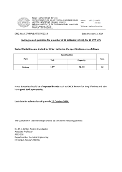


© Copyright 2026