
Ultra-high Q even eigenmode resonance in terahertz metamaterials
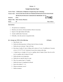
Ultra-high Q even eigenmode resonance in terahertz metamaterials
Ibraheem Al-Naib, Yuping Yang, Marc M. Dignam, Weili Zhang, and Ranjan Singh
Citation: Applied Physics Letters 106, 011102 (2015); doi: 10.1063/1.4905478
View online: http://dx.doi.org/10.1063/1.4905478
View Table of Contents: http://scitation.aip.org/content/aip/journal/apl/106/1?ver=pdfcov
Published by the AIP Publishing
Articles you may be interested in
Ultrabroadband reflective polarization convertor for terahertz waves
Appl. Phys. Lett. 105, 181111 (2014); 10.1063/1.4901272
Polarization-sensitive microelectromechanical systems based tunable terahertz metamaterials using three
dimensional electric split-ring resonator arrays
Appl. Phys. Lett. 102, 161912 (2013); 10.1063/1.4803048
Ultrastrong light-matter coupling at terahertz frequencies with split ring resonators and inter-Landau level
transitions
J. Appl. Phys. 113, 136510 (2013); 10.1063/1.4795543
Leaky and bound modes in terahertz metasurfaces made of transmission-line metamaterials
J. Appl. Phys. 113, 033105 (2013); 10.1063/1.4776761
Dual-band terahertz metamaterials based on nested split ring resonators
Appl. Phys. Lett. 101, 091103 (2012); 10.1063/1.4748163
This article is copyrighted as indicated in the article. Reuse of AIP content is subject to the terms at: http://scitation.aip.org/termsconditions. Downloaded to IP: 72.53.67.34
On: Tue, 06 Jan 2015 16:54:02
APPLIED PHYSICS LETTERS 106, 011102 (2015)
Ultra-high Q even eigenmode resonance in terahertz metamaterials
Ibraheem Al-Naib,1,a) Yuping Yang,2 Marc M. Dignam,1 Weili Zhang,2 and Ranjan Singh3,b)
1
Department of Physics, Engineering Physics and Astronomy, Queen’s University, Kingston,
Ontario K7L 3N6, Canada
2
School of Electrical and Computer Engineering, Oklahoma State University, Stillwater, Oklahoma 74078,
USA
3
Centre for Disruptive Photonic Technologies, Division of Physics and Applied Physics, School of Physical
and Mathematical Sciences, Nanyang Technological University, Singapore, Singapore 637371
(Received 22 October 2014; accepted 22 December 2014; published online 6 January 2015)
We report the simultaneous excitation of the odd and the even eigenmode resonances in a periodic
array of square split-ring resonators, with four resonators per unit cell. When the electric field is
parallel to their gaps, only the two well-studied odd eigenmodes are excited. As the resonators are
rotated relative to one another, we observe the emergence and excitation of an extremely sharp
even eigenmode. In uncoupled split-ring resonators, this even eigenmode is typically radiative in
nature with a broad resonance linewidth and low Q-factor. However, in our coupled system, for
specific range of rotation angles, our simulations revealed a remarkably high quality factor
(Q 100) for this eigenmode, which has sub-radiant characteristics. This type of quad-supercell
metamaterial offers the advantage of enabling access to all the three distinct resonance features of
the split-ring resonator, which consists of two odd eigenmodes in addition to the high-Q even
eigenmode, which could be exploited for high performance multiband filters and absorbers. The
high Q even eigenmode could find applications in designing label free bio-sensors and for studying
C 2015 AIP Publishing LLC.
the enhanced light matter interaction effects. V
[http://dx.doi.org/10.1063/1.4905478]
The terahertz (THz) gap in the electromagnetic spectrum
has been an intense area of research over the last decade. Due
to the shortage of efficient sources and detectors, the THz regime has been a relatively underexplored region of the electromagnetic spectrum in comparison to the microwave and
the optical bands. Hence, there has been a sustained effort to
develop basic system components to manipulate the THz radiation such as filters, modulators, sensors, waveguides, and
imaging devices.1–3 Metamaterials (MTMs) represent a revolutionary technology for the development of THz components
with simple designs by employing planar structures due to
their reconfigurable properties and ease of fabrication. As a
result, these materials have been widely utilized at THz frequencies for the development of novel devices.4–6 They are
mainly designed as a planar array of subwavelength metallic
resonators, namely, the split-ring resonators (SRRs).
The concept of MTMs relies heavily on the resonance
properties of the SRRs. Various MTM configurations have
been proposed to manipulate the fundamental and higher
order resonances in SRRs.7,8 Moreover, the influence of near
and far field electromagnetic field coupling between SRRs
with different orientations has been investigated by several
groups.9–21 Sharp, high quality factor (Q-factor) resonances
are of particular importance, as they can be utilized to realize
narrow-band filters,22–24 slow light devices, and ultrasensitive thin-film sensors.24–29 It has been observed that conventional planar MTMs have quite low quality factors due to the
high radiation and Joule losses. At THz frequencies, the resonance linewidths in MTMs are limited by radiation losses
a)
Electronic mail: [email protected]
b)
Electronic mail: [email protected]
0003-6951/2015/106(1)/011102/5/$30.00
as the ohmic losses are quite low in most plasmonic metals
in this frequency regime.30,31 One of the most common strategies to control radiation losses in MTMs is to break the
symmetry of double split resonators; these are typically
known as asymmetric split-ring resonators (ASRs).32–34 In
ASRs, a Fano-like asymmetric lineshape resonance32,35 with
a high Q is excited. Various designs of ASRs have been proposed for filtering,24 slow-light devices,35 sensing,36,37 and
lasing spasers.38 In addition to the ASRs, high Q resonances
can also be excited in MTMs through different coupling
schemes among the meta-molecules, by forming a supercell
that consists of a group of closely spaced SRRs.
Individual SRRs, such as those shown in Fig. 1, typically support odd or even eigenmodes. However, the simultaneous excitation of both even and odd eigenmodes is
forbidden due to the symmetry constraints of the structure
with respect to the incident electric field. At normal incidence, when the electric field is parallel to the gap of the
SRRs, odd resonances are excited. The lower frequency odd
FIG. 1. Microscopic image of the three sample arrays; the SRRs are rotated
around their centers as indicated by the arrows with an angle h: (a) 0 , (b)
45 , and (c) 75 .
106, 011102-1
C 2015 AIP Publishing LLC
V
This article is copyrighted as indicated in the article. Reuse of AIP content is subject to the terms at: http://scitation.aip.org/termsconditions. Downloaded to IP: 72.53.67.34
On: Tue, 06 Jan 2015 16:54:02
011102-2
Al-Naib et al.
mode is called as the fundamental inductive–capacitive (LC)
resonance (n ¼ 1), and the higher order mode (n ¼ 3) is quadrupolar in nature.8 When the incident electric field is perpendicular to the gap bearing arms of the SRR, only the even
eigenmode (n ¼ 2) with dipolar characteristic is excited. The
dipolar (n ¼ 2) resonance mode is highly radiative in nature
due to parallel oscillating currents and have low Q factors.14
In this work, we report two distinct findings (a) the simultaneous excitation of the odd and the even eigenmodes
and (b) ultra-high Q 100 subradiant dipolar resonance excitation (n ¼ 2). We achieve the simultaneous excitation of
odd and even eigenmodes by choosing a quad SRR design
that forms a supercell. When the four SRRs are gradually
rotated around their respective centers (as indicated in Fig.
1), we observe the emergence of an ultra-sharp even eigenmode that appears between the already-excited odd eigenmodes in the transmitted spectrum. We also perform a
systematic study to understand the effects of mutual interaction among the quad SRRs by sweeping the rotation angle.
We find from our simulations that an ultrahigh Q-factor of
98 can be achieved for very small angle of 2 under the horizontal polarization, and vice-versa at 88 under the vertical
polarization.
Three different MTM arrays with different mutual rotation angles were considered: 0 , 45 , and 75 as shown in
Figs. 1(a)–1(c), respectively. Each SRR has a side length of
l ¼ 36 lm, a width of w ¼ 6 lm, a gap of g ¼ 3 lm, and periodicity of the supercell of p ¼ 120 lm. They are patterned as a
200 nm gold layer on top of a 640 lm thick silicon wafer
(refractive index of 3.42) using conventional photolithography. The transmission through the MTM samples was determined using a typical terahertz time-domain spectroscopy
(THz-TDS) system.39 A reference scan was taken using a
bare silicon wafer and was followed by a measurement of
the fabricated MTM samples. All the measurements were
performed at a normal incidence such that the electric (E)
and magnetic (H) fields of the incident radiation were in the
MTM plane. Two orthogonal polarizations of electric field
excitation were considered, first horizontal with the electric
field along the x-axis and then vertical with electric field
along the y-axis.
The measured transmission spectra for horizontal and
vertical polarizations for the three samples are shown in
Figs. 2(a) and 2(c), respectively; while the corresponding numerical simulations are shown in Figs. 2(b) and 2(d). The
simulations have been performed using the commercial software Microwave Studio CST. Its frequency domain solver,
which is based on finite element method to solve the
Maxwell equations, has been employed to calculate the
transmission amplitude. Moreover, unit cell boundary conditions along with Floquet ports have been employed.
Reasonable agreement has been obtained between the simulations and the measurements. The simulations reproduce the
main features of the measurements such as the excitation of
all resonances and their resonance frequencies. We attribute
the discrepancy in the sharpness of the resonances between
the theory and the experiments to the limited resolution of
the measurements which were performed with a 17 ps time
scan. We are limited to a 17 ps scan due to the Fabry-Perot
reflections arising from the rear surface of the substrate.
Appl. Phys. Lett. 106, 011102 (2015)
FIG. 2. Measured ((a) and (c)) and simulated ((b) and (d)) amplitude transmission spectra for the three samples with different rotation angles for horizontal ((a) and (b)) and vertical ((c) and (d)) polarizations. The shaded blue,
yellow, and green areas are a guide to the approximate frequency ranges of
the resonances of n ¼ 1, 2, and 3 eigenmodes, respectively.
When the exciting electric field is horizontally polarized
(see Figs. 2(a) and 2(b)) and the rotation angle is 0 , the odd
eigenmodes of the quad SRRs resonate, namely, the LC
mode (n ¼ 1) at about 0.5 THz and the quadrupole (n ¼ 3)
eigenmode at about 1.5 THz. From simulations, we find that
rotating the quad SRRs by an angle as small as 1 around
their centers (not shown) allow the excitation of the even
eigenmode (n ¼ 2) between the aforementioned odd eigenmodes at about 1 THz. This is due to the additional asymmetry
of the rotated quad SRRs with respect to the excitation field.
When the rotation angle is increased to 45 , the even eigenmode is enhanced and well defined. As the rotation angle is
further increased to 75 , the even eigenmode and the quadrupole mode (n ¼ 3) merge and give rise to the conventional
dipolar even eigenmode, and more interestingly the LC,
n ¼ 1 resonance dip becomes much narrower and shallower.
The Q-factor of the LC mode, defined as Q ¼ fr/Df, where fr
is the resonance frequency and Df is the full width at half
maximum (FWHM), is enhanced by a factor of four at the
75 rotation angle to a final value of Q ¼ 24.3, compared to a
value of Q ¼ 6.2 when the SRRs are not mutually rotated.
In the case of vertical polarization, where the exciting
electric field is aligned with the y-axis (see Figs. 2(c) and
2(d)), when the rotation angle is 0 , only the even, n ¼ 2
eigenmode, which is clearly a dipole resonance, appears in
the spectral response of the SRR supercell array. Rotating
the quad SRRs allows the odd eigenmodes to be excited
This article is copyrighted as indicated in the article. Reuse of AIP content is subject to the terms at: http://scitation.aip.org/termsconditions. Downloaded to IP: 72.53.67.34
On: Tue, 06 Jan 2015 16:54:02
011102-3
Al-Naib et al.
simultaneously, i.e., both the LC resonance at the lower frequency of 0.5 THz and the n ¼ 3 eigenmode at the higher frequency of 1.5 THz are excited. The dipolar even eigenmode
undergoes a tremendous line narrowing of its resonance,
which is a transition from a highly radiating dipole mode to
a subradiant dipole resonance mode. This is mainly caused
by the coherent near field interaction between the quad SRRs
of the supercell. The response of the 45 rotated quad SRRs
is identical to the other polarization which is not surprising.
However, at 75 rotation angle the behavior is very interesting as one can see that all three resonances are clearly
excited and the even eigenmode has a very high Q-factor of
45 in the simulation. Conversely, the measured Q is only 21
due to the limited time scan. This behavior can exactly be
seen at a rotation angle of 15 under the horizontal polarization. The other two odd eigenmodes revealed Q-factors of
5.8 and 4.6 for the LC and quadrupole modes, respectively.
The discrepancy in the experimental and simulated Q-factor
for these two modes is less than 8%.
We now examine the critical angles at which the different resonances appear and disappear. To accomplish this, we
simulated the quad SRRs in steps of angular rotation of 2 at
each polarization. The results are shown in Figs. 3(a) and
3(b), where the electric field is horizontal and vertical,
respectively. In the case of a horizontal electric field, only
the two odd eigenmodes are excited at an angle of 0 as mentioned earlier. Interestingly, the LC eigenmode exhibits quite
large narrowing until it nearly disappears at an angle of 80 .
FIG. 3. Simulated transmission amplitude as a function of the rotation angle
(h) for the horizontal (a) and vertical (b) polarization.
Appl. Phys. Lett. 106, 011102 (2015)
The quadrupole mode red-shifts, broadens, and almost
merges with the even eigenmode beyond an angle of 60 .
The most fascinating event is the immediate appearance of
the previously forbidden even eigenmode at about 1 THz
with 2 of angular rotation and its extremely sharp nature
(Q ¼ 98). However, the resonance modulation depth [1 –
(the transmission depth at resonance)] is quite low (2.4%)
for small rotation angles and only increases gradually. We
would like to stress here that the even eigenmode is the dark
eigenmode that is forbidden at a rotation angle of 0 and it is
only when the symmetry is broken by introducing a small
angular rotation that we observe the appearance of the sharp
dark eigenmode as it is very weakly coupled to the free
space. As the degree of asymmetry is enhanced by increasing
the angular rotation, this dark even eigenmode broadens with
an enhancement in the amplitude depth. We will return to a
discussion of the trade-off between the Q-factor and the amplitude modulation towards the end of the paper. The range
of the rotation angles at which all the odd and even modes
remain excited falls between 1 and 55 .
For the vertical electric field case in Fig. 3(b), only the
dipole mode is excited at the 0 angle of rotation, since in this
case, the odd modes (n ¼ 1,3) remain dark and unexcited. The
LC eigenmode appears at the rotation angle of about 10 beyond
which its resonance linewidth broadens. The even dipole mode
(n ¼ 2) transitions from a radiative low Q resonance to a subradiant high Q dipole resonance as the quad SRRs are rotated
gradually. The high Q characteristic of this even eigenmode
exists between angles of 56 and 88 (25.5 < Q < 98). As aforementioned, the measured Q-factor at a rotation angle of 75 is
21 only, while the simulated one is 45. In order to achieve a
higher spectral resolution and measure such a high Q-factor resonance, a longer time scan is required and hence either freestanding sample40 or a thicker substrate on the order of few
millimeters should be employed. Instead, continuous-wave THz
spectrometers can be utilized for the measurements as they can
offer a resolution of less than 1 GHz.41
In order to understand the physical mechanism behind
the sharpness of the even eigenmode of the quad SRRs, we
investigate the simulated surface current and electric field
distributions for the vertical polarization with a 75 rotation
angle as shown in Fig. 4 at the respective resonance frequencies, fn. The distributions clearly show the characteristic
behavior of the n ¼ 1, n ¼ 2, and n ¼ 3 modes, where “n”
denotes the eigenmode of the SRR. As can be seen in Figs.
4(a) and 4(d), respectively, the current is large at the first resonance (f1 ¼ 0.5 THz) and the electric field is mainly confined in the gap of the SRRs. Most notably, the current
distribution in each horizontally neighboring SRRs is out-ofphase. This explains the narrow linewidths, especially at
small rotation angle where there is a quite large cancellation
of the dipole moment. More interestingly, at the even eigenmode resonance (f2 ¼ 0.993 THz), we observe parallel surface currents along the side arms of the SRR (n ¼ 2) as
shown in Fig. 4(b) and is also evident in the field distribution
in Fig. 4(e). It is important to emphasize that the surface current is out-of-phase in the neighboring SRRs in both the horizontal and vertical directions. Therefore, the cancellation of
the dipole moment is maximum in this case, which explains
the subradiant nature of this particular eigenmode. At the
This article is copyrighted as indicated in the article. Reuse of AIP content is subject to the terms at: http://scitation.aip.org/termsconditions. Downloaded to IP: 72.53.67.34
On: Tue, 06 Jan 2015 16:54:02
011102-4
Al-Naib et al.
Appl. Phys. Lett. 106, 011102 (2015)
FIG. 4. Simulated surface current and
electric field distribution at angle
h ¼ 75 of (a) and (d) LC resonance,
(b) and (e) even eigenmode resonance,
and (c) and (f) quadrupole mode for
the vertical polarization.
third resonance f3 ¼ 1.462 THz, the conventional quadrupole
resonance is observed. The surface current as well as the
field confinement shown in Figs. 4(c) and 4(f) are quite weak
in agreement with the simulated and experimental results
shown in Figs. 2(c) and 2(d), respectively.
After analyzing the transmission response and the current distributions for the two polarizations, we performed a
parametric study of the effect of the rotation angle (h) on the
behavior of the particularly interesting even eigenmode
(n ¼ 2). Fig. 5 shows the modulation depth (left scale) and
the Q factor (right scale) versus the rotation angle when the
electric field is vertically polarized. The Q-factor increases
dramatically as the rotation angle changes from 60 to 90 ,
while the modulation depth decreases rapidly, going to zero
for an angle of 90 . There is an obvious desire to maximize
the Q factor and the modulation depth of the resonances, but
our results shows that there is a trade-off between these two
quantities. For example, we find from our simulations that a
Q-factor of 100 is achievable, but only with a modulation
depth of 2.4%.
To conclude, we have demonstrated a supercell for a
MTM structure where even and odd eigenmodes are excited
simultaneously. This design can also support extremely
sharp high Q even eigenmode that was previously known to
be highly radiative and low Q in nature. The supercell consists of four interacting SRRs that are mutually rotated. The
specific even eigenmode that allows the observation of such
sharp resonances has been explored in detail. We also demonstrate that we could engineer the Q factor and the amplitude depth of each resonance of the SRR by controlling the
mutual rotation angle of the SRRs. The MTMs that we have
designed can be used for various applications, e.g., for the
realization of ultrasensitive sensors and narrowband filters.
The design principles we have introduced could be applied
to other geometries of MTMs across large parts of the electromagnetic spectrum.
We thank NTU startup Grant No. M4081282 and MoE
Tier 1 Grant No. M4011362 for funding of this research.
This work was partially supported by the U.S. National
Science Foundation (Grant No. ECCS-1232081).
1
M. Tonouchi, Nat. Photonics 1, 97–105 (2007).
P. U. Jepsen, D. G. Cooke, and M. Koch, Laser Photonics Rev. 5, 124–166
(2011).
3
A. Tuniz, K. J. Kaltenecker, B. M. Fischer, M. Walther, S. C. Fleming, A.
Argyros, and B. T. Kuhlmey, Nat. Commun. 4, 2706 (2013).
4
T. J. Yen, W. J. Padilla, N. Fang, D. C. Vier, D. R. Smith, J. B. Pendry, D.
N. Basov, and X. Zhang, Science 303, 1494–1496 (2004).
5
H.-T. Chen, J. F. O’Hara, A. K. Azad, and A. J. Taylor, Laser Photonics
Rev. 5, 513–533 (2011).
6
I. Al-Naib, C. Jansen, R. Singh, M. Walther, and M. Koch, IEEE Trans.
Terahertz Sci. Technol. 3, 772–782 (2013).
7
R. Singh, C. Rockstuhl, F. Lederer, and W. Zhang, Appl. Phys. Lett. 94,
021116 (2009).
8
J. Wallauer, A. Bitzer, S. Waselikowski, and M. Walther, Opt. Express 19,
17283–17292 (2011).
9
N. Liu, S. Kaiser, and H. Giessen, Adv. Mater. 20, 4521–4525 (2008).
2
FIG. 5. Modulation depth (left scale) and Q-factor (right scale) achieved
when sweeping the angle (h) for the vertical polarization. The lines are
meant as guides for the eye. The circles and stars show the modulation depth
and the Q-factor, respectively.
This article is copyrighted as indicated in the article. Reuse of AIP content is subject to the terms at: http://scitation.aip.org/termsconditions. Downloaded to IP: 72.53.67.34
On: Tue, 06 Jan 2015 16:54:02
011102-5
10
Al-Naib et al.
R. S. Penciu, K. Aydin, M. Kafesaki, T. Koschny, E. Ozbay, E. N.
Economou, and C. M. Soukoulis, Opt. Express 16, 18131–18144 (2008).
11
N. Feth, M. K€onig, M. Husnik, K. Stannigel, J. Niegemann, K. Busch, M.
Wegener, and S. Linden, Opt. Express 18, 6545–6554 (2010).
12
D. R. Chowdhury, R. Singh, M. Reiten, J. Zhou, A. J. Taylor, and J. F.
O’Hara, Opt. Express 19, 10679–10685 (2011).
13
I. Al-Naib, R. Singh, C. Rockstuhl, F. Lederer, S. Delprat, D. Rocheleau, M.
Chaker, T. Ozaki, and R. Morandotti, Appl. Phys. Lett. 101, 071108 (2012).
14
I. Sersic, M. Frimmer, E. Verhagen, and A. F. Koenderink, Phys. Rev.
Lett. 103, 213902 (2009).
15
F. Hesmer, E. Tatartschuk, O. Zhuromskyy, A. A. Radkovskaya, M.
Shamonin, T. Hao, C. J. Stevens, G. Faulkner, D. J. Edwards, and E.
Shamonina, Phys. Status Solidi 244, 1170–1175 (2007).
16
N. Born, I. Al-Naib, C. Jansen, T. Ozaki, R. Morandotti, and M. Koch,
Appl. Phys. Lett. 104, 101107 (2014).
17
G. Kumar, A. Cui, S. Pandey, and A. Nahata, Opt. Express 19, 1072–1080
(2011).
18
I. Al-Naib, E. Hebestreit, C. Rockstuhl, F. Lederer, D. Christodoulides, T.
Ozaki, and R. Morandotti, Phys. Rev. Lett. 112, 183903 (2014).
19
R. Singh, I. Al-Naib, D. R. Chowdhury, L. Cong, C. Rockstuhl, and W.
Zhang, Appl. Phys. Lett. 105, 081108 (2014).
20
H. Liu, Y. M. Liu, T. Li, S. M. Wang, S. N. Zhu, and X. Zhang, Phys.
Status Solidi 246, 1397–1406 (2009).
21
W.-C. Chen, J. J. Mock, D. R. Smith, T. Akalin, and W. J. Padilla, Phys.
Rev. X 1, 021016 (2011).
22
H. Tao, A. C. Strikwerda, K. Fan, W. J. Padilla, X. Zhang, and R. D.
Averitt, Phys. Rev. Lett. 103, 147401 (2009).
23
O. Paul, R. Beigang, and M. Rahm, Opt. Express 17, 18590–18595
(2009).
24
C. Jansen, I. A. I. Al-Naib, N. Born, and M. Koch, Appl. Phys. Lett. 98,
051109 (2011).
25
I. A. I. Al-Naib, C. Jansen, and M. Koch, Appl. Phys. Lett. 93, 083507 (2008).
Appl. Phys. Lett. 106, 011102 (2015)
26
J. F. O’Hara, R. Singh, I. Brener, E. Smirnova, J. Han, A. J. Taylor, and
W. Zhang, Opt. Express 16, 1786–1795 (2008).
J. F. O’Hara, W. Withayachumnankul, and I. Al-Naib, J. Infrared
Millimeter Terahertz Waves 33, 245–291 (2012).
28
W. Withayachumnankul, H. Lin, K. Serita, C. M. Shah, S. Sriram, M.
Bhaskaran, M. Tonouchi, C. Fumeaux, and D. Abbott, Opt. Express 20,
3345–3352 (2012).
29
B. Reinhard, K. M. Schmitt, V. Wollrab, J. Neu, R. Beigang, and M.
Rahm, Appl. Phys. Lett. 100, 221101 (2012).
30
K. L. Tsakmakidis, M. S. Wartak, J. J. H. Cook, J. M. Hamm, and O.
Hess, Phys. Rev. B 81, 195128 (2010).
31
R. Singh, Z. Tian, J. Han, C. Rockstuhl, J. Gu, and W. Zhang, Appl. Phys.
Lett. 96, 071114 (2010).
32
V. A. Fedotov, M. Rose, S. L. Prosvirnin, N. Papasimakis, and N. I.
Zheludev, Phys. Rev. Lett. 99, 147401 (2007).
33
I. A. I. Al-Naib, C. Jansen, and M. Koch, Electron. Lett. 44, 1228–1229
(2008).
34
R. Singh, I. A. I. Al-Naib, M. Koch, and W. Zhang, Opt. Express 19,
6312–6319 (2011).
35
B. Luk’yanchuk, N. I. Zheludev, S. A. Maier, N. J. Halas, P. Nordlander,
H. Giessen, and C. T. Chong, Nat. Mater. 9, 707–715 (2010).
36
C. Debus and P. H. Bolivar, Appl. Phys. Lett. 91, 184102 (2007).
37
Y. Chen, I. A. I. Al-Naib, J. Gu, M. Wang, T. Ozaki, R. Morandotti, and
W. Zhang, AIP Adv. 2, 022109 (2012).
38
N. I. Zheludev, S. L. Prosvirnin, N. Papasimakis, and V. A. Fedotov, Nat.
Photonics 2, 351–354 (2008).
39
D. Grischkowsky, S. Keiding, M. van Exter, and C. Fattinger, J. Opt. Soc.
Am. B 7, 2006–2015 (1990).
40
H. Tao, A. C. Strikwerda, K. Fan, C. M. Bingham, W. J. Padilla, X.
Zhang, and R. D. Averitt, J. Phys. D: Appl. Phys. 41, 232004 (2008).
41
A. Roggenbuck, H. Schmitz, A. Deninger, I. C. Mayorga, J. Hemberger,
R. G€
usten, and M. Gr€
uninger, New J. Phys. 12, 043017 (2010).
27
This article is copyrighted as indicated in the article. Reuse of AIP content is subject to the terms at: http://scitation.aip.org/termsconditions. Downloaded to IP: 72.53.67.34
On: Tue, 06 Jan 2015 16:54:02


© Copyright 2026