
E025 - Atos
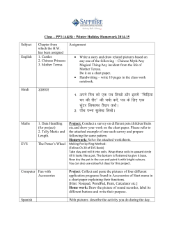
www.atos.com Table E025-8/E Solenoid directional valves type DKE direct operated, ISO 4401 size 10 Spool type, two or three position direct operated valves with threaded solenoids certified according the North American standard cURus. Solenoids are made by: • wet type screwed tube, different for AC and DC power supply, with integrated manual override pin • interchangeable coils, specific for AC or DC power supply, easily replaceable without tools - see section 쪫 for available voltages Standard coils protection IP65, optional coils with IP67 AMP Junior Timer or lead wire connections. The valve body is 5 chamber type for all DC versions and for AC safety version /FI and FV Standard AC version uses 3 chamber type body Wide range of interchangeable spools , see section 쪨. The body is made by shell-moulding casting with wide internal passages ensuring low pressure drops Mounting surface: ISO 4401 size 10 Max flow: 150 l/min Max pressure: 350 bar BLEED SCREW DKE-161*/WP-AC (3 CHAMBERS BODY) BLEED SCREW DKE-17*-DC (5 CHAMBERS BODY) 1 MODEL CODE DKE - 1 61 1 /A - X 24 DC ** /* Series number Seals material, see section 쪪: = NBR PE = FKM BT = HNBR Directional control valves size 10 Valve configuration, see section 쪨 61 = single solenoid, center plus external position, spring centered 63 = single solenoid, 2 external positions, spring offset 67 = single solenoid, center plus external position, spring offset 70 = double solenoid, 2 external positions, without springs 71 = double solenoid, 3 positions, spring centered 75 = double solenoid, 2 external positions, with detent Voltage code, see section 쪫 00-AC = AC solenoids without coils 00-DC = DC solenoids without coils X = without connector See section 14 for available connectors, to be ordered separately Coils with special connectors, see section 11 XJ = AMP Junior Timer connector XK = Deutsch connector XS = Lead Wire connection Spool type, see section 쪨. Options, see note 1 at section 쪪. 2 CONFIGURATIONS and SPOOLS (representation according to ISO 1219-1) Configurations 61 1 Configurations Spools 1 0 0 1 0 2 1 0 2 2 1 0 2 63 Spools 1 0 1 2 2 61/A 67 1 0 2 0 0 2 5 1 3 4 63/A 1 2 6 7 8 70 1 2 0/2 1/2 67/A 0 91 19 93 39 75 2/2 1 2 71 1 0 2 58 1/9 Note: see also section 쪪 note 3 for special shaped spools E025 3 SEALS AND HYDRAULIC FLUIDS - for other fluids not included in below table, consult our technical office Assembly position / location Any position for all valves except for type - 170* (without springs) that must be installed with horizontal axis if operated by impulses Subplate surface finishing MTTFd values according to EN ISO 13849 Roughness index Ra 0,4 - flatness ratio 0,01/100 (ISO 1101) 150 years, for further details see technical table P007 Standard execution = -30°C ÷ +70°C /PE option = -20°C ÷ +70°C /BT option = -40°C ÷ +70°C NBR seals (standard) = -20°C ÷ +60°C, with HFC hydraulic fluids = -20°C ÷ +50°C FKM seals (/PE option)= -20°C ÷ +80°C HNBR seals (/BT option)= -40°C ÷ +60°C, with HFC hydraulic fluids = -40°C ÷ +50°C Ambient temperature Seals, recommended fluid temperature Recommended viscosity 15÷100 mm2/s - max allowed range 2.8 ÷ 500 mm2/s Fluid contamination class Hydraulic fluid ISO 4406 class 21/19/16 NAS 1638 class 10, in line filters of 25 μm (β10 > _ 75 recommended) Classification Ref. Standard Suitable seals type DIN 51524 NBR, FKM, HNBR HL, HLP, HLPD, HVLP, HVLPD Mineral oils FKM HFDU, HFDR NBR, HNBR HFC Flame resistant without water Flame resistant with water ISO 12922 Rated flow As shown in the symbols of table 쪨 Ports P,A,B: 350 bar; Port T 210 bar for DC version (250 bar with option /Y); 160 bar for AC version See diagrams Q/Δp at section 쪬 Maximum flow 150 l/min, see operating limits at section 쪭 Flow direction Operating pressure 3.1 Coils characteristics Insulation class H (180°C) for DC coils F (155°C) for AC coils Due to the occuring surface temperatures of the solenoid coils, the European standards EN ISO 13732-1 and EN ISO 4413 must be taken into account IP 65 (with connectors 666, 667, 669 correctly assembled) 100% See electric feature 쪫 ± 10% CURUS North American Standard Protection degree to DIN EN 60529 Relative duty factor Supply voltage and frequency Supply voltage tolerance Certification 4 NOTES 1 Options A = Solenoid mounted at side of port B (only for single solenoid valves). In standard versions, solenoid is mounted at side of port A. WP = prolonged manual override protected by rubber cap - see section 12 . WPD/KE-DC = (only for DC supply) manual override with detent, to be ordered separately, see tab. K150 L, L1, L2, L3, LR, L7, L8 see section 10 = device for switching time control (only for DC solenoids). L7 and L8 are available only for spool type 0/1, 1/1, 3/1, 4 and 5. FI, FV = 5 chambers body for DC and AC versions with proximity switch for spool position monitoring: see tab. E110. Y = external drain, only for DC version, to be selected if the pressure at T port is higher than the max allowed limits. 2 Type of electric connectors DIN 43650, to be ordered separately - see section 13 . 666 = standard connector IP-65 for direct connection to electric supply source. 667 = as 666, but with built-in signal led. 669 = with built-in rectifier bridge for supplying DC coils by alternate current (AC 110V and 230V - Imax 1A). 3 Spools - spools type 0 and 3 are also available as 0/1 and 3/1 with restricted oil passages in central position, from user ports to tank. - spool type 1 is also available as 1/1, properly shaped to reduce the water-hammer shocks during the switching. - spool type 1/9 has closed center in rest position but it avoids the pressurization of A and B ports due to the internal leakages. 5 ELECTRIC FEATURES External supply nominal voltage ± 10% Voltage code 12 DC 12 DC CAE-12DC 14 DC 14 DC CAE-14DC 24 DC 24 DC CAE-24DC 28 DC 28 DC 110 DC 110 DC 220 DC 220 DC 110/50/60 AC 110/50/60 AC 230/50/60 AC 230/50/60 AC 115/60 AC 115/60 AC 230/60 AC 230/60 AC 110/50/60 AC 110 DC 230/50/60 AC 220 DC Type of connector Power consumption (2) 36 W 666 CAE-28DC CAE-110DC or CAE-220DC 667 669 Code of spare coil 100 VA (3) CAE-110/50/60AC (1) 130 VA (3) CAE-115/60AC 36 W CAE-230/50/60AC (1) CAE-230/60AC CAE-110DC CAE-220DC (1) In case of 60 Hz voltage frequency the performances are reduced by 10÷15% and the power consumption is 90 VA (2) Average values based on tests performed at nominal hydraulic condition and ambient/coil temperature of 20°C. (3) When solenoid is energized, the inrush current is approx 3 times the holding current. 6 Q/ΔP DIAGRAMS based on mineral oil ISO VG 46 at 50°C DKE Flow direction Spool type 0, 0/1, 0/2, 2/2 A A B B 1, 1/1, 1/9, 6, 8 A A D C 3, 3/1, 7 A A C D 4 B B B B F G 5, 58 A B C C 1/2 B C C B 19, 91 F F G G H 39, 93 F F G G H Valve pressure drop Δp [bar] P씮A P씮B A씮T B씮T P씮T B씮A H 18 G 15 F E 12 D C 9 B A 6 3 0 25 50 75 100 125 150 Flow rate [l/min] 7 OPERATING LIMITS based on mineral oil ISO VG 46 at 50°C The diagrams have been obtained with warm solenoids and power supply at lowest value (Vnom - 10%). The curves refer to application with symmetrical flow through the valve (i.e. P씮A and B씮T). In case of asymmetric flow and if the valves have the devices for controlling the switching times the operating limits must be reduced. DKE - AC 360 240 B C D 180 120 25 50 75 Curve AC A 0/1 180 120 0 100 125 150 300 Spool type U Z 240 180 120 60 25 50 75 0 100 125 150 25 50 75 100 125 150 Flow rate [l/min] Flow rate [l/min] DC 0, 0/1, 1, 1/1, 3, 3/1, 1/2, 0/2, 8 B 4, 5, 19, 91 6, 7 C 0, 1/1, 3, 3/1 19, 91 D 1, 1/2, 0/2 4, 5 E 6, 7, 8, 2/2 2/2 U Z - 4, 5 0/1, 1/1, 3/1 SWITCHING TIMES (average values in msec) Switch-on AC Switch-on DC Switch-off AC Switch-off DC DKE + 666 / 667 40 60 25 35 DKE + 669 60 –– 90 –– DKE-*/L* –– 75÷150 –– 45÷150 DKE-*/L7 - DKE-*/L8 –– 100÷150 –– 100÷150 Valve Test conditions: - 50 l/min; 150 bar - nominal supply voltage - 2 bar of back pressure on port T - mineral oil ISO VG 46 at 50°C The elasticity of the hydraulic circuit and the variations of the hydraulic characteristics and temperature affect the response time. SWITCHING FREQUENCY Valve DKE + 666 / 667 AC (cycles/h) DC (cycles/h) 7200 15000 L L1, L2, L3 LR DEVICES FOR SWITCHING TIME CONTROL These devices are only available for DC valve version (5 chambers body) and can control the switching time and therefore reduce the coil hammering in the hydraulic circuit. The different types are available shown in the figure. - L: controls and regulates the switching time in both moving directions of the spool: regulation is carried out by screwing/unscrewing the element itself (regulating choke); - L1/L2/L3: controls the switching time in both moving directions of the spool by means of fixed calibrated restrictor (gauged flow). The restrictor is positioned in the valve’s body ØL1 = 1,25 mm; ØL2 = 1 mm; ØL3 = 0,75 mm; - LR: controls and regulates the switching time in the B씮A direction of the spool movement. The device does not control the switching time (standard time) in the opposite direction A씮B of the spool movement. - L7/L8: controls the switching time in both moving directions of the spool by means of fixed calibrated restrictor (gauged flow). The restrictor is installed in the solenoid’s anchor. For a correct operation of the switching time control, the passage in which the control device is installed must be completely filled with oil. ØL1=1,25 mm; ØL2=1 mm; ØL3=0,75 mm; Ø 10 A 240 Flow rate [l/min] 9 B 60 60 8 C 300 Inlet pressure [bar] E Inlet pressure [bar] Inlet pressure [bar] E D A 300 0 DKE - DC / options L7, L8 DKE - DC 360 360 L7 = Ø1,2 mm L8 = Ø1,0 mm E025 11 COILS TYPE CAE WITH SPECIAL CONNECTORS (only for 12DC, 14DC, 24DC and 28DC) ø64.6 12 ø64.6 74.5 Options -XS Coil type CAES Lead Wire connection Cable lenght = 180 mm 70.5 91 70.5 83.5 70.5 Options -XK Coil type CAEK Deutsch connector, DT-04-2P male Protection degree IP67 81 Options -XJ Coil type CAEJ AMP Junior Timer connector Protection degree IP67 74.5 ø64.6 74.5 INSTALLATION DIMENSIONS [mm] ISO 4401: 2005 Mounting surface according to 4401-05-05-0-05 (without X port, Y port optional) Fastening bolts: 4 socket head screws M6x40 class 12.9 Tightening torque = 15 Nm Seals: 5 OR 2050 and 1 OR 108 Ports P,A,B,T: Ø = 11.5 mm (max) Ports Y: Ø = 5 mm valve surface P = PRESSURE PORT A, B= USE PORT T = TANK PORT Y = DRAIN PORT (only for option /Y) For the max pressures on ports, see section 쪩 DKE-17*-AC DKE-16*-AC 30 73 112.5 10 26.5 48.5 27 = = 92.2 = = Option /WP 26.5 26.5 92.2 73 73 70 73 Mass: 3,9 kg Mass: 4,7 kg DKE-17*-DC DKE-16*-DC 30 73 106.5 10 49 27 = = 92.2 25.5 25.5 = = Option /WP 25.5 92.2 100 100 70 100 Mass: 4,5 kg Mass: 6,1 kg Standard manual override PIN. The manual override operation can be possible only if the pressure at T ports is lower than 50 bar Bleed screw 13 ELECTRIC CONNECTORS ACCORDING TO DIN 43650 The connectors must be ordered separately CONNECTOR WIRING 666, 667 (for AC or DC supply) 666, 667 27 14 1 = Positive 2 = Negative = Coil ground 27 42 30 28.5 SUPPLY VOLTAGES 667 666 24 AC or DC All 110 AC or DC voltages 220 AC or DC MOUNTING SUBPLATES Ports location Model Ø Counterbore GAS Ports [mm] A-B-P-T (X-Y) A-B-P-T (X-Y) 1/2" (1/4") 30 (21,5) Mass [kg] BA-308 (/Y) Ports A, B, P, T (X, Y) underneath BA-428 (/Y) Ports A, B, P, T (X, Y) underneath 3/4" (1/4") 36,5 (21,5) 5,5 BA-434 (/Y) Ports P, T, (X, Y) underneath; ports A, B on lateral side 3/4" (1/4") 36,5 (21,5) 8,5 The subplates are supplied with 4 fastening bolts M6x40. Also available are multi-station subplates and modular subplates. For further details see table K280. 12/14 2,5


© Copyright 2026