
Bristan_OvalRange_Installation
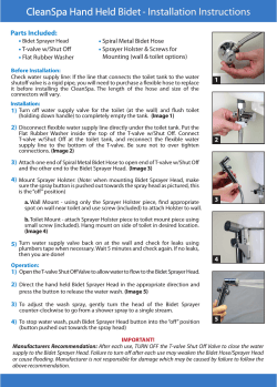
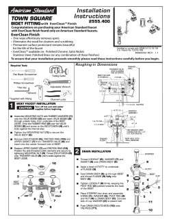
Oval Range
Fitting Instructions & Contents List
P l e a s e k e e p t h e s e i n s tr u ct i o n s f o r f u tu r e r e f e r e n c e a n d r e qu e s t o f r e p l a c e me n t p a r ts
1. Introduction
Thank you for choosing Bristan, the UK’s leading taps and showers expert. We have designed this product with
your enjoyment in mind. To ensure that it works to its full potential, it needs to be fitted correctly. These fitting
instructions have been created to give you all of the information you need and, if you need any further help, please
do not hesitate to give us a call on 0844 701 6273.
2. Safety Note
Please read these instruction thoroughly and retain for future use.
All product manufactured and supplied by Bristan are safe provided they are installed correctly, used correctly and
receive regular maintenance in accordance with these instructions.
These fittings need to be installed in accordance with and meet the requirements of the Water Supply (Water
Fittings) Regulations 1999 and Scottish Byelaws 2004.
Before starting any installation please consider the following:
Prior to drilling into walls, check that there are no hidden electrical
wires, cables or water supply pipes. This can be checked with the aid of
SAFETY
NOTE
an electronic detector.
If power tools are used do not forget to:
- Wear eye protection
- Unplug equipment after use
3. Specification
Operating pressure range (bar)
Min.
Max.
0.2
10.0
Maximum static pressure – 10.0 bar
NOTE:- Nominally equal (balanced) inlet supply pressures are recommended for optimum performance.
Designed to comply with BS EN 200 for single taps/ combination taps and BS EN 817 for single lever taps, for water
systems of type 1 and 2 general technical specifications and to be used within systems designed to BS 6700. BS
6700 recommends the temperature of stored water should never exceed 65°C. A stored water temperature of 60°C
is considered sufficient to meet all nominal requirements and will minimise the build up of lime scale in hard water
areas.
Installation – Basin / Bath taps
1. Identify all components and check for completeness, particularly before commencing installation.
2.
Install the taps to the basin/bath. The backnut (9) and washer (10) are used to secure the taps to the surface
of
the basin/bath with the washers (7) above.
3. Connect the hot and cold water supplies.
4.
Turn on the water supplies. Open both taps, letting the water
flow for a few minutes to check all joints and connections for leaks.
Contents
1. Cap
2. Grub Screw
3. Head
4. Valve
5. Body
6. Flow Straightener
7. Rubber Washer
8. Inlet Tail
9. Backnut
10.Washer
11.Washer
x2
x2
x2
x2
x2
x2
x2
x2
x2
x2
x2
Basin (no waste) Bidet Mixer
1. Identify all components and check for completeness, particularly before commencing installation.
2. Install mixer to the basin/bidet. Secure the mixer to the surface of the basin/bidet, using the fixing kit, with the
washer (8) above basin.
3. Screw in connecting flexi tail pipes by hand ONLY (DO NOT OVERTIGHTEN) and then connect the hot and cold
supplies.
4. Fit the pop-up waste, (if applicable) with the flat washer below and the shaped washer above the basin/bidet. It is
advised that a silicon sealant be applied to both sealing faces of the washers. The plug height can be set by
adjusting the waste rod, operating rod, rod connector and then screw in the base of the plug.
Friction for the waste mechanism can be adjusted using the waste cap. (DO NOT OVERTIGHTEN).
PLEASE NOTE: (Bidet Mixer Only)
The operating rod needs to be fed through from the underside of the mixer before fitting to bidet and then screw on
operating rod knob. Please make sure waste operating rod fits through the hole in the bidet to connect pop-up
waste before final fixing.
Bidet Mixer
Contents
1.
2.
3.
4.
5.
6.
7.
8.
9.
10.
11.
12.
13.
14.
15.
16.
17.
18.
19.
20.
21.
22.
23.
10
8
Cap
Grub Screw
Head
Shroud
Locking nut
Cartridge
x1
Body
Washer
Flow Straightener
Nozzle Assembly
Rubber ‘C’ Washer
Metal ‘C’ Washer
Fixing Nuts
Fixing Studs
Flexi Tails
x2
Operating Rod
Pop up link
Waste Plug
Waste Flange
Waste Washers
Waste Body
Friction Adjustment Screwx1
Horizontal Screw
x1
x1
x1
x1
x1
x1
x1
x1
x1
x1
x1
x2
x2
x1
x1
x1
x1
x2
x1
x1
Basin Mixer (no waste)
CONTENTS
1. Cap
2. Grub Screw
3. Head
4. Shroud
5. Locking Nut
6. Cartridge
7. Body
8. Washer
9. Flow Straightener
10.Flexi Tails
11.Rubber ‘C’ Washer
12.Metal ‘C’ Washer
13.Fixing Nuts
14.Fixing Studs
15.Washer
x1
x1
x1
x1
x1
x1
x1
x1
x1
x2
x1
x1
x2
x1
x1
(See ADDITIONAL
SAFETY FEATURE)
9
8
ECO CLICK
An innovative water saving feature that offers a subtle resistance
as it reaches, approximately half of its full flow capability. For
increased flow this feature can be overridden. At full flow the
click cartridge uses 32% less water than a standard cartridge
and when in eco click mode the reduction increases to 72%.
ADDITIONAL SAFETY FEATURE
This mixer tap incorporates a facility to limit/reduce the maximum hot water from the tap. Remove the handle by
pulling the cap (1) out of the handle at the back and undo the grub screw (2) then pull off handle. A small plastic
collar (temperature limiting ring) can be seen between the cartridge retaining nut (5) and the control shaft. Carefully
prise the plastic collar upwards using a small screwdriver or similar tool. By replacing in a slightly different position
by either rotating either to the left or the right, this can limit the lever movement (when moved towards the hot or
the cold side), thus allowing the maximum hot temperature to be altered as required.
Bath shower mixer / Bath filler
1. Identify all components and check for completeness, particularly before commencing installation.
2. Install the mixer body to the bath using the backnuts (8) and washers (6) provided under the bath.
3. FOR THE BATH SHOWER MIXER ONLY: Fit the hose to the mixer, underneath the spout to diverter (11 & 13).
4. Fix the wall bracket to the wall ensuring that the handset and hose will reach it.
5. Connect the hot and cold water supplies and turn water supplies on.
6. Fully open the valves (4) by turning handles (3), letting it run for a few minutes to check for leaks.
7. Operate the mixer in both bath and shower mode. To switch from bath to shower mode, pull the diverter knob (9)
up. After use, the mixer automatically reverts to the bath filling mode.
CONTENTS
1. Cap
2. Grub Screw
3. Head
4. Valve
5. Body
6. Washer
7. Inlet Tails
8. Backnut
9. Diverter Knob
10. Flow Straightener Assembly
11. Diverter Valve
12. O-Ring
13. Hose Outlet
14. Washer
CONTENTS
1. Cap
2. Grub Screw
3. Head
4. Valve
5. Body
6. Washer
7. Inlet Tails
8. Backnut
9. Flow Straightener Assembly
10.Washer
x2
x2
x2
x2
x1
x2
x2
x2
x1
x2
x2
x2
x2
x2
x1
x2
x2
x2
x1
x1
x1
x1
x1
x2
IMPORTANT - PLEASE READ
These fitting needs to be installed in accordance with the following
following Installation Requirements and Notes
(IRN) to ensure they meet the requirements of the Water Supply (Water
(Water Fittings) Regulations 1999 and the
Scottish Byelaws 2004.
IRN R001 (OL ½ C, OL ¾ C, OL BID C, OL EBASNW C, OL BF C, OL BSM C)
See text of entry for Installation Requirements or Notes.
IRN R006 (OL ½ C, OL ¾ C, OL BID C, OL EBASNW C, OL BF C)
This tap or combination tap assembly has a Type AUK3 air gap and is therefore for installation in any premises to
protect against a backflow risk up to a Fluid Category 5.
IRN R010 (OL BID C, OL EBASNW C, OL BF C)
Schedule 22- 15 (1)
Water supplies shall be a reasonably balanced pressures from a common source (e.g. hot and cold supplies both
from the same storage or both from a supply pipe). Where the fitting is supplied from unbalanced supplies (e.g. hot
and cold supplies from separate sources) a Listed’ single check valve or some other no less effective backflow
prevention device shall be fitted immediately upstream of both hot and cold water inlets.
IRN R040 (OL BSM C)
Schedule 22- 15 (1)
The fitting shall be installed so that its outlet discharges above the spill-over level of any fixed appliance as indicated
below:For backflow protection in domestic or installations up to, and including, Fluid Category 3.
1.
Size of tap or combination fitting.
2.
Vertical distance of outlet above spill-over level.
1. Not exceeding 1/2 in
20mm
2. Exceeding 1/2 in but not exceeding 3/4 in
25mm
3. Exceeding 3/4 in
70mm
If the fitting cannot be installed as indicated in the table it shall be installed:
a) with an approved double check valve assembly or some other no less effective backflow
prevention device immediately upstream of the inlet; or
b) so that it draws water by gravity only from a cistern, or cylinder having a permanently
open vent pipe, and the distributing pipe supplies no other fitting (other than draining tap) at a
lower level.
For backflow protection in premises or installations up to, and including Fluid Category 5.
The vertical distance of the outlet above the spill-over level shall be not less than 20mm or twice the diameter of the
inlet pipe to the fitting, which ever is the greater.
If the fitting cannot be installed as indicated it shall be installed with a backflow prevention arrangement suitable for
the Fluid Category.
IRN R070 (OL BID C)
The water supply (Water Fittings) Regulations 1999 and the Water Bylaws 2000, Scotland preclude the
connection of rim feed ascending spray type bidets with hand – held spray attachments directly to any
supply pipe.
BIDETS WITH OVEROVER - RIM SUPPLY ARRANGEMENTS
(a)
Bidets installed in domestic locations of the over – rim type, that have no ascending spray and/or flexible
hose may be supplied with cold and hot water through single or combination tap assemblies from either
a supply pipe or distributing pipe providing that a Type AUK2 air gap is provided between the outlet of the
water fitting and the spillover level of the bidet and shall also comply with (c) below.
(b)
Bidets installed in premises other than domestic locations of the over – rim type, that have no ascending
spray and / or flexible hose where a higher fluid category of risk may be present, may be supplied with
cold and hot water through single or combination tap assemblies from either a supply pipe or a
distributing pipe providing that a Type AUK3 air gap is provided between the outlet of the water fitting and
the spillover level of the bidet as (a) above and shall also comply with (c) below.
(c)
In case of a bidet equipped with a single outlet (single flow) mixing tap, shall also be installed in
accordance with IRN R010. See Diagram 1 below
Diagram 1
BIDETS (INCLUDING WCS ADAPTED AS BIDETS) WITH SUBMERGED WATER INLETS
IN LETS AND / OR
FLEXIBLE HOSE WITH SPRAY OR JET HANDSET FITTINGS
Bidets, including WCs adapted as bidets, incorporating and ascending spray inlet or utilising a flexible hose or an
arrangement with a spray or jet, are a fluid category 5 risk in that the ascending spray inlet could be
contaminated with urine or other matter and the spray or jet handset could be deposited in the bidet or WC.
Bidets of this type must not be supplied with water from a cold or hot water supply pipe or a common distributing
pipe. The zone of backflow risk is shown and the highest part of this zone must be not less that 15mm below any
cistern serving the bidet. See Diagram 2 below.
Diagram 2
Bidets of this type may:
a.
Be supplied with cold and / or hot water through type AA, AB, AD or AUK1 backflow prevention
arrangement or type DC device serving the bidet only. See Diagram 3: or
Diagram 3
Type AA, AB, AD or AUK1 air gap with or without blended water cistern
cistern or type DC backflow Prevention
device.
b.
Be supplied with cold water from an independent distributing pipe serving the bidet only, or a common
distributing pipe serving the bidet and which may also serve a WC or urinal flushing cistern at a lower
level. See Diagram 4; or
c.
Be supplied with hot water from a water heater, which is supplied from an independent distributing
pipe, that serves the bidet only. See Diagram 4: or
Diagram 4
d.
Where the bidet is at a lower elevation than any other outlets or appliances, be supplied with water from a
common cold and / or hot water vented distribution pipe providing that;
(i)
(ii)
the elevation of the spillover level of the bidet, if there is no flexible hose; or
the elevation of the spray outlet, with the hose extended vertically above the spillover
level of the bidet
Whichever is the highest, is not less than 300mm below the point of connection with the distributing
pipe which serves over appliances or outlets. See Diagram 5.
Diagram 5
The method of supplying water to an ascending spray and / or hose and spray bidet is illustrated in Diagram 3
and which is described in the formal guidance, is difficult to achieve in practice. The air gap should be located
above the fully extended hose and spray, or zone of backflow risk, and this height may need to be increased to
provide sufficient water pressure, to overcome friction loss in the pipes and fittings, in order to operate the
ascending spray and hose spray effectively. This method of supplying blended water to a bidet involves
complicated control methods as the control of water to the bidet itself has to be linked with the control of water
flow, and temperature, upstream of the air gap, blended water cistern or DC device.
5. Cleaning & Maintenance
Your fitting has a high quality finish and should be treated with care to preserve the visible surfaces.
All finishes will wear if not cleaned correctly. The only safe way to clean your product is to wipe with a soft damp
cloth. Stains can be removed using washing up liquid. All bathroom cleaning product (powders and liquids) will
damage the surface of your fitting, even the non-scratch cleaners.
NOTE:- Never use abrasive detergents or disinfectants or those containing alcohol, hydrochloric or phosphoric
acid.
We advise that your fitting is regularly serviced, particularly in hard water areas.
Bristan recommend E-Cloth for cleaning all of our bathroom & kitchen products.
Using just water, E-cloth gives a smear free, deep clean by breaking up and
holding dirt, which normal cloths leave behind. Order through your Bristan
stockist.
(ORDER CODE: ECLOTH)
10
Bristan Guarantee
2 year -
Pumps, Power Showers
2 year parts. 1 year labour (subject to registration).
Electric Showers/Instantaneous Water Heaters
2 year parts. 1 year labour (subject to registration).
5 year -
Taps and Mixers
5 year parts and 1 year labour (subject to proof of purchase).
Shower Valves
5 year parts. 5 year labour (subject to registration), else 1 year with proof of purchase.
Accessories
5 year parts only. Includes bathrooms accessories, shower accessories (e.g. hoses, handsets and
poles), wastes, WC levers and light pulls.
10 year -
Shower enclosures, Shower Trays, Sanitary Ware & Furniture
10 year parts (subject to registration), else 2 years with proof of purchase. 1 year labour (subject
to registration), else 1 year with proof of purchase.
This guarantee applies to products purchased within the United Kingdom or Republic of Ireland, but does not apply
to products used commercially.
The guarantee is only available to original purchasers who have proof of purchase.
The installation must allow ready access to all products for the purpose of inspection, maintenance or
replacement.
Any part found to be defective during the above guarantee period will be replaced without charge, providing that the
product has been installed in accordance with the instructions, used as intended, and regularly serviced.
Servicing should be carried out at regular intervals of no more than 12 months and more frequently in hard water
areas (heavy lime scale) areas.
In the unlikely event that any problems are encountered with the product’s performance on installation, you must
obtain guidance/authorisation from our Customer Service Department, and be able to supply proof and date of
purchase, before any remedial action is taken.
The guarantee excludes general wear and tear and damage caused by accident, misuse or neglect, and does not
cover the following:
Components that are subject to general wear and tear such as filters, seals, ‘O’ rings and washers etc.
· Damage caused by faulty installation
· Damage caused by lime scale or any waterborne debris
· Damage caused by inappropriate cleaning products (see user instructions)
· Damage caused by the use of non-Bristan parts
· The product being used for a purpose other than intended by the manufacturer.
In the interests of continuous product improvement Bristan reserves the right to alter specification as necessary.
11
This booklet covers all product codes
OL ½ C / OL ¾ C / OL BID C / OL EBASNW C / OL BF C / OL BSM C
Helpline
0844 701 6273
Bristan Group Limited
Birch Coppice Business Park, Dordon, Tamworth, Staffordshire B78 1SG
A Masco Company
Website: www.bristan.com
Telephone: 0844 7016 274
Facsimile: 0844 701 6275
Email: [email protected]
FI (OVAL RANGE) – REV. D3


© Copyright 2026