
Cooler Bulkhead Instructions
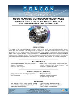
FERMENTER’S FAVORITESTM
EXTERIOR WALL
WELDLESS
COOLER BULKHEAD
INSIDE
LOCKNUT
SMALL
O - RING
INTERIOR WALL
OUTSIDE
WASHER 2
( FOR 3⁄ 8” THICK
WALL OR LESS )
LARGE
O - RING
WASHER
1
NIPPLE
COUPLER
INSTALLING THE COOLER BULKHEAD
1. Remove the factory-installed spigot on the cooler.
Remove the locknut, both silicone o-rings and both
steel washers from the threaded nipple on the bulkhead.
2. If the wall of your cooler is less than 3/8” thick, put both
washers on the threaded nipple; otherwise only put
one washer on the threaded nipple.
4. Place the bulkhead assembly inside the cooler and
push the threaded nipple through the spigot hole. The
large o-ring should be resting against the inside wall
of the cooler.
5. On the outside of the cooler, place the small o-ring
on the nipple and push it against the outside
wall of the cooler.
6. Thread the locknut onto the nipple and tighten it until
it just touches the large o-ring.
7. Hand-tighten from the inside only — do not use pliers.
Over-tightening of the locknut can damage the o-ring.
8. Once snug, the locknut can be tightened the rest of the
way from the outside.
3. Put the large silicone o-ring on the nipple and push the
o-ring and the washer(s) all the way back.
FERMENTER’S FAVORITESTM
EXTERIOR WALL
WELDLESS
KETTLE BULKHEAD
INSIDE
LOCKNUT
O - RING
INTERIOR WALL
OUTSIDE
O - RING
WASHER
NIPPLE
COUPLER
INSTALLING THE KETTLE BULKHEAD
1. Drill a 7/8” hole in your kettle. Remove the locknut,
both silicone o-rings and the washer from the
threaded nipple on the bulkhead.
3. Place the bulkhead assembly inside the kettle and push
the threaded nipple through the hole. The o-ring
should be resting against the inside wall of the kettle.
2. Put the steel washer on the threaded nipple, then put
one silicone o-ring on the nipple and push the o-ring
and the washer all the way back.
4. On the outside of the kettle, place the second o-ring
on the nipple and push it against the outside
wall of the kettle.
5. Thread the locknut onto the nipple and tighten it until
it just touches the large o-ring.
6. Hand-tighten from the inside only — do not use pliers.
Over-tightening of the locknut can damage the o-ring.
7. Once snug, the locknut can be tightened the rest of the
way from the outside.
FERMENTER’S FAVORITE
EXTERIOR WALL
VALVE & BULKHEAD
ASSEMBLY FOR
COOLERS
INSIDE
1
⁄ 2” BARB
VALVE
LOCKNUT
INTERIOR WALL
OUTSIDE
LARGE
O - RING
( INCLUDED
WITH
SOME MODELS )
SMALL WASHER 2 WASHER
O - RING ( FOR 3⁄ 8” THICK
WALL OR LESS )
NIPPLE
COUPLER
INSTALLING THE VALVE & BULKHEAD ASSEMBLY FOR COOLERS
1. Remove the factory-installed spigot on the
cooler, and unscrew the ball valve from the
bulkhead assembly. Remove the locknut, both
silicone o-rings and both steel washers from the
threaded nipple on the bulkhead.
2. If the wall of your cooler is less than 3/8”
thick, put both steel washers on the threaded
nipple; otherwise only put one washer on the
threaded nipple.
and push the o-ring and the washer(s)
all the way back.
6. Thread the locknut onto the nipple and tighten it
until it just touches the large o-ring.
4. Place the bulkhead assembly inside the cooler
and push the threaded nipple through the spigot
hole. The small o-ring should be resting against
the inside wall of the cooler.
5. On the outside of the cooler, place the large
o-ring on the nipple and push it against the
outside wall of the cooler.
3. Put the small silicone o-ring on the nipple
EXTERIOR WALL
FERMENTER’S FAVORITE
VALVE & BULKHEAD
ASSEMBLY FOR
KETTLES
INSIDE
1
⁄ 2” BARB
VALVE
( INCLUDED
WITH
SOME MODELS )
LOCKNUT
LARGE
O - RING
INTERIOR WALL
OUTSIDE
SMALL WASHER 2 WASHER
O - RING ( FOR 3⁄ 8” THICK
WALL OR LESS )
NIPPLE
COUPLER
INSTALLING THE KETTLE VALVE ASSEMBLY
1. Drill a 7/8” hole in your kettle. Unscrew the ball
valve frovm the bulkhead assembly. Remove
the locknut, both silicone o-rings and the steel
washer from the threaded nipple on the bulkhead.
2. Put the steel washer on the threaded nipple, then
put one silicone o-ring on the nipple and push
the o-ring and the washer all the way back.
3. Place the bulkhead assembly inside the kettle and
push the threaded nipple through the hole. The
o-ring should be resting against the inside wall
of the kettle.
4. On the outside of the kettle, place the second
o-ring on the nipple and push it against the
outside wall of the kettle.
5. Thread the locknut onto the nipple and tighten it
until it just touches the large o-ring.
7. Once snug, the locknut can be tightened the rest
of the way from the outside.
8. Put teflon tape on the threaded nipple and attach
the ball valve.
9. Fill the kettle with water to leak-test the valve.
6. Tighten from the inside only — hand-tighten,
then use pliers. Initial tightening of the locknut
from the outside can damage the o-ring.
FERMENTER’S FAVORITE
EXTERIOR WALL
VALVE & BULKHEAD
ASSEMBLY FOR
COOLERS
INSIDE
1
⁄ 2” BARB
VALVE
LOCKNUT
( INCLUDED
WITH
SOME MODELS )
INTERIOR WALL
OUTSIDE
LARGE
O - RING
SMALL WASHER 2 WASHER
O - RING ( FOR 3⁄ 8” THICK
WALL OR LESS )
NIPPLE
COUPLER
INSTALLING THE VALVE & BULKHEAD ASSEMBLY FOR COOLERS
1.Turn locknut onto nipple until snug.
Make sure o-ring groove faces cooler.
2.Slide o-ring onto nipple and
seat in groove.
4.On the inside of the cooler, slide the
o-ring over threaded nipple and push
against wall of cooler.
5.Slide washer against o-ring.
6.Thread coupler on loosely
9.Snug up assembly by hand, tightening
coupler from inside.
10.Fill the cooler with water to leaktest the valve.
7.Apply thread tape or sealant to
valve end of nipple.
FERMENTER’S FAVORITE
EXTERIOR COOLER WALL
3.From the outside push the nipple
through cooler hole.
8.Thread valve onto nipple, tighten
against locknut.
VALVE & BULKHEAD
ASSEMBLY FOR
KETTLES
INSIDE
1
⁄ 2” BARB
( INCLUDED WITH
SOME MODELS )
VALVE
LOCKNUT
O - RING
INTERIOR COOLER WALL
OUTSIDE
O - RING
WASHER
NIPPLE
COUPLER
INSTALLING THE KETTLE VALVE ASSEMBLY
1.Turn locknut onto nipple until snug.
Make sure o-ring groove faces kettle.
2.Slide o-ring onto nipple and
seat in groove.
3.From the outside push the nipple
through cooler hole.
4.On the inside of the kettle, slide the
o-ring over threaded nipple and push
against wall of kettle.
5.Slide washer against o-ring.
6.Thread coupler on loosely
7.Apply thread tape or sealant to
valve end of nipple.
8.Thread valve onto nipple, tighten
against locknut.
9.Snug up assembly by hand, tightening
coupler from inside.
10.Fill the kettle with water to leaktest the valve.
1.
FERMENTER’S FAVORITE
VALVE & BULKHEAD
ASSEMBLY FOR
KETTLES
VALVE
LOCKNUT
NIPPLE
O-RINGS
WASHER
COUPLER
3a.
2a.
2b.
3b.
4a.
4b.
5a.
5b.
INSTALLING THE KETTLE VALVE ASSEMBLY
1.Begin by disassembling the valve and
bulkhead assembly. Remove the valve,
coupler, steel washer, and both silicone
O-rings. This will leave you with only
the nipple and locknut.
3.Place one O-ring on the nipple and
push it all the way to the locknut, then
insert the assembly through the hole
in the kettle. The O-ring should be
resting on the outside of the kettle.
5.Slide the Washer onto the nipple, then
thread on the coupler. Hand tighten
the coupler until snug, then tighten
further by holding the coupler in place
and rotating the valve until hand tight.
2.Ensure the locknut is threaded on to
the nipple as far as it will go. Apply
3 wraps of thread tape to the nipple
(on the side where fewer threads
are showing), and then thread into
the ball valve.
4.On the inside of the kettle, place the
other O-ring on the nipple and push it
against the inside wall of the kettle.
6.Fill with water to leak test. If leaking
from the O-rings next to the kettle
wall, ensure that the O-rings are properly seated and try slightly tightening the locknut. If leaking from
the ball valve, remove and apply
more thread tape.
FERMENTER’S FAVORITE
VALVE & BULKHEAD ASSEMBLY FOR KETTLES
1.
1. Begin by disassembling the valve and
bulkhead assembly. Seperate the coupler,
steel washer, and both silicone O-rings.
This will leave you with only the nipple
and locknut to remove from the valve.
LOCKNUT
VALVE
O-RINGS
NIPPLE
2a.
2b.
3a.
3b.
4a.
4b.
5a.
5b.
COUPLER
WASHER
2. Ensure the locknut is threaded on to the
nipple as far as it will go. Apply 3 wraps
of thread tape to the nipple (on the side
where fewer threads are showing), and
then thread into the ball valve.
3. Place one O-ring on the nipple and push
it all the way into the groove of the
locknut, then insert the assembly through
the hole in the kettle. The O-ring should
be resting on the outside of the kettle.
4. On the inside of the kettle, place the
other O-ring on the nipple and push it
against the inside wall of the kettle.
5. Slide the Washer onto the nipple, then
thread on the coupler. Hand tighten the
coupler until snug, then tighten further
by holding the coupler in place and rotating the valve until hand tight.
Fill with water to leak test. If leaking from the O-rings next to the kettle wall, ensure that the O-rings are properly
PRO TIP seated and try slightly tightening the locknut. If leaking from the ball valve, remove and apply more thread tape.
FERMENTER’S FAVORITE
VALVE & BULKHEAD ASSEMBLY FOR COOLERS
1.
1. Begin by disassembling the valve and
bulkhead assembly. Seperate the coupler,
steel washer, and both silicone O-rings.
This will leave you with only the nipple
and locknut to remove from the valve.
3
LOCKNUT
VALVE
O-RINGS
NIPPLE
2a.
2b.
3a.
3b.
4a.
4b.
5a.
5b.
WASHER
WASHER
(For 3⁄8” thick
wall or less)
COUPLER
2. Ensure the locknut is threaded on to the
nipple as far as it will go. Apply 3 wraps
of thread tape to the nipple (on the side
where fewer threads are showing), and
then thread into the ball valve.
3. Place the small O-ring on the nipple and
push it all the way into the groove of the
locknut, then insert the assembly through
the hole in the cooler. The O-ring should
be resting on the outside of the cooler.
4. On the inside of the cooler, place the
large O-ring on the nipple and push it
against the inside wall of the cooler.
5. Slide the Washer(s) onto the nipple, then
thread on the coupler. Hand tighten the
coupler until snug, then tighten further
by holding the coupler in place and rotating the valve until hand tight.
Fill with water to leak test. If leaking from the O-rings next to the cooler wall, ensure that the O-rings are properly
PRO TIP seated and try slightly tightening the locknut. If leaking from the ball valve, remove and apply more thread tape.
SIGHT GLASS AND THERMOMETER FITTING FOR COOLERS
sight glass
compression
fitting
flat steel o-ring
2x rubber o-ring
flat steel o-ring
housing
o-ring
o-ring
outside
inside
compression
fitting for
thermometer
housing
t-joint
washer
nipple
washer
coupler
optional plug
for use without
thermometer
1. 1. DRILL A 3/8” HOLE THROUGH THE COOLER WALL.
2. 2. PUT ONE WASHER AND ONE O-RING ON THE COUPLER
NIPPLE; holding the coupler inside the cooler, put the nipple through the hole.
The o-ring should be against the cooler wall.
3. 3. PUT THE OTHER O-RING ON THE NIPPLE ON THE OUTSIDE
OF THE COOLER; push it against the cooler wall, and then put the other
washer on the nipple.
4. 4. THREAD THE T-JOINT ONTO THE NIPPLE ON THE OUTSIDE
OF THE COOLER. Hold the coupler stationary inside the cooler with pliers
and tighten the t-joint from the outside until snug. Align the t-joint so that the
brass compression fitting is pointing up.
5. 5. PLACE THE SIGHT GLASS INTO THE COMPRESSION FITTING
AT THE TOP OF THE T-JOINT AND MARK DESIRED HEIGHT.
While the sight glass is in place, mark the cooler for placement of the eyebolt.
6. 6. REMOVE THE SIGHT TUBING AND CUT TO DESIRED
LENGTH.
7. 7. INSTALL THE EYEBOLT BY SCREWING INTO EXTERIOR
COOLER WALL.
8. 8. SLIDE THE SIGHT GLASS THROUGH THE EYEBOLT AND
THEN INTO THE TOP COMPRESSION FITTING AND TIGHTEN.
9. 9. IF THE FITTING WILL BE USED FOR A SIGHT GLASS ONLY,
REMOVE THE SECOND COMPRESSION FITTING AND INSTALL
THE PLUG.
10. 10. IF THE FITTING WILL BE USED FOR A THERMOMETER AS
WELL, SLIP THE THERMOMETER STEM THROUGH THE BRASS
SIGHT GLASS AND THERMOMETER FITTING FOR KETTLES
sight glass
compression
fitting
flat steel o-ring
2x rubber o-ring
flat steel o-ring
housing
o-ring
o-ring
outside
inside
compression
fitting for
thermometer
housing
t-joint
washer
washer
nipple
coupler
optional plug
for use without
thermometer
1. 1. DRILL A 3/8” HOLE THROUGH THE KETTLE WALL.
2. 2. PUT ONE WASHER AND ONE O-RING ON THE COUPLER
NIPPLE; holding the coupler inside the kettle, put the nipple through the hole.
The o-ring should be against the kettle wall.
3. 3. PUT THE OTHER O-RING ON THE NIPPLE ON THE OUTSIDE
OF THE KETTLE; PUSH IT AGAINST THE KETTLE WALL, AND
THEN PUT THE OTHER WASHER ON THE NIPPLE.
4. 4. THREAD THE T-JOINT ONTO THE NIPPLE ON THE OUTSIDE
OF THE KETTLE. Hold the coupler stationary inside the kettle with pliers and
tighten the t-joint from the outside until snug. Align the t-joint so that the brass
compression fitting is pointing up.
5. 5. PLACE THE SIGHT GLASS INTO THE COMPRESSION FITTING
AT THE TOP OF THE T-JOINT AND MARK DESIRED HEIGHT.
While the sight glass is in place, mark the kettle for placement of the eyebolt.
6. 6. REMOVE THE SIGHT TUBING AND CUT TO DESIRED
LENGTH.
7. 7. DRILL A 1/4” HOLE IN THE KETTLE AT THE EYEBOLT MARK,
AND INSTALL THE EYEBOLT.
8. 8. SLIDE THE SIGHT GLASS THROUGH THE EYEBOLT AND
THEN INTO THE TOP COMPRESSION FITTING AND TIGHTEN.
9. 9. IF THE FITTING WILL BE USED FOR A SIGHT GLASS ONLY,
REMOVE THE SECOND COMPRESSION FITTING AND INSTALL
THE PLUG.
10. 10. IF THE FITTING WILL BE USED FOR A THERMOMETER AS
WELL, SLIP THE THERMOMETER STEM THROUGH THE BRASS
COMPRESSION NUT AND THE SMALL WASHER AND O-RINGS.
flat steel o-ring
2x rubber o-ring
flat steel o-ring
THERMOMETER BULKHEAD FOR KETTLES
o-ring
o-ring
outside
inside
compression
fitting for
thermometer
housing
1. 1. DRILL A 3/8” HOLE THROUGH THE KETTLE
WALL.
2. 2. PUT ONE WASHER AND ONE O-RING ON THE
COUPLER NIPPLE; HOLDING THE COUPLER
INSIDE THE KETTLE, PUT THE NIPPLE THROUGH
THE HOLE. THE O-RING SHOULD BE AGAINST THE
KETTLE WALL.
3. 3. PUT THE OTHER O-RING ON THE NIPPLE ON
THE OUTSIDE OF THE KETTLE; PUSH IT AGAINST
THE KETTLE WALL, AND THEN PUT THE OTHER
WASHER ON THE NIPPLE.
4. 4. THREAD THE COMPRESSION FITTING ONTO
THE NIPPLE ON THE OUTSIDE OF THE KETTLE.
Hold the coupler stationary inside the kettle with pliers and tighten
the compression fitting from the outside until snug.
5. 5. SLIP THE THERMOMETER STEM THROUGH THE
COMPRESSION NUT AND THE SMALL WASHER
washer
washer
nipple
coupler
flat steel o-ring
2x rubber o-ring
flat steel o-ring
THERMOMETER BULKHEAD FOR COOLERS
o-ring
o-ring
outside
inside
compression
fitting for
thermometer
housing
washer
1. 1. DRILL A 3/8” HOLE THROUGH THE COOLER WALL.
2. 2. PUT ONE WASHER AND ONE O-RING ON THE COUPLER NIPPLE;
HOLDING THE COUPLER INSIDE THE COOLER, PUT THE NIPPLE
THROUGH THE HOLE. The o-ring should be against the cooler wall.
3. 3. PUT THE OTHER O-RING ON THE NIPPLE ON THE OUTSIDE OF THE
COOLER; PUSH IT AGAINST THE COOLER WALL, AND THEN PUT THE
OTHER WASHER ON THE NIPPLE.
4. 4. THREAD THE COMPRESSION FITTING ONTO THE NIPPLE ON THE
OUTSIDE OF THE COOLER. Hold the coupler stationary inside the cooler with pliers
and tighten the compression fitting from the outside until snug.
5. 5. SLIP THE THERMOMETER STEM THROUGH THE COMPRESSION NUT
AND THE SMALL WASHER AND O-RINGS. Omit the washer if the stem is larger
than 3/16”.
nipple
washer
coupler
WELDLESS ADAPTER FOR 1/2” MPT THERMOMETERS
1/2” mpt
thermometer
(not included)
outside
inside
washer
1. 1. CHOOSE THE LOCATION OF THE THERMOMETER ON THE KETTLE.
2. 2. DRILL A 7/8” HOLE IN THE SPOT YOU WISH TO LOCATE THE THERMOMETER.
3. 3. PLACE THE STAINLESS WASHER AND ONE O-RING OVER THE MPT
THREADS OF THE THERMOMETER AND INSERT THE THERMOMETER
INTO THE HOLE; the o-ring should be against the kettle wall.
4. 4. PLACE THE SECOND O-RING OVER THE THERMOMETER STEM AND
THREADS ON THE INSIDE OF THE KETTLE.
5. 5. THREAD THE LOCKNUT ONTO THE THREADS.
6. 6. HOLDING THE THERMOMETER IN PLACE, TIGHTEN THE LOCKNUT
o-ring
o-ring
locknut


© Copyright 2026