
Method and apparatus for measuring
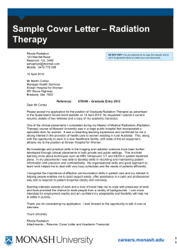
Aug. 22, 1944.
Re. 22,531
D. G. c. HARE
METHOD AND APPARATUS FOR MEASURING THICKNESS
Original Filed June 26. 1940
4 Sheets-Sheet l
l2
FIG. 2
36
DONALD G.C.HARE
‘
BY A
HIS
XNV‘NTOR
-
ATTGRNEIYS
Aug. 22, 1944.
Re. 22,531
D. G. c. HARE
METHOD AND APPARATUS FOR MEASURING THICKNESS
Original Filed June 26. 1940
4 Sheets-Sheet 2
FIG. 4
H6. 3
26
2a
\
59%,
E139
24
FIG. 8
FIG.9
DONALD G.C.HARE
INVENTOR
BY
H l5
ATTORNEYS
Aug. 22, 1944.
D. G. c. HARE
Re. 22,531
METHOD AND APPARATUS FOR MEASURING THICKNESS
Original Filed June 26. 1940
4 Sheets-Sheet 5
800-‘
100-
\—“T
I
(n
SCATTERED
INTENSITY
g
600- z
(ARBUNITS)
6 it
I”
I ‘n
q
‘q
I- o
500- j
o‘
g
o-
—
N
x
<
N
g
400
O
2
o‘
I
I
5
I
l0
I
I5
l
20
I
25_
3O
I
35
DISTANCE lN CM.
FIG. 7
CALIBRATION CURVE
WALL THICKNESS VSI R.
: AV. INTENSITY AT THICKNESS t.
0.6-1
WHERE R
AV. INTENSITY FOR tI= 0.574
0.5
0.4
wAI_I_
THICKNESS 0.3-
I.
t (INCHES)
0.2
m -
\
‘I
\
0.0
0.5
.
I
05
0.7
R.
I
I
I
0.8
0.9
L0
/
,
DONALD G.C. HARE
INVENTOR
MI,
STAN DARD
ATTORN EY
Aug. 22, 1944.
D. G. c. HARE
Re- 22531
METHOD AND APPARATUS FOR MEASURING THICKNESS
Original Filed June 26. 1940
4 Sheets-Sheet 4
FIG. 11
60A
' '
""IIIIIII
DQNALD G.C. HARE
III
INVENTOR
%
‘ MU"
mz/kww
60B
HIS
ATTOR EYS
'
Re. 22,531
Reiaued Aug. 22, 1944
UNITED STATES PATENT OFFICE
22,531
' METHOD AND
APPARATUS FOR MEASURING
THICKNESS
,
Donald G. C. Hare, Roslyn, N. Y., asslgnor, by
mesne assignments, to The Texas Company,
- New York, N. Y., a corporation of Delaware
Original No. 2,277,756, dated March 31, 1942, Se
rial No. 342,422, June 26, 1940. Application for
reissue April 22, 1944, Serial No. 532,318
10 Claims. (Cl. 250—83.6)
layers of the material. However, the most serious
This invention relates to the measurement of
di?iculty with both electric and magnetic methods
thickness and particularly to a method and an
is that both depend to a large extent on the con
apparatus for measuring the thickness of the
dition of strain and temperature of the material,
walls of receptacles or pipes adapted to contain
and, particularly for the magnetic case, upon the
or conduct liquids, such, for instance, as the
physical history of the specimen. The e?ects
shells of oil stills or the walls of tubes adapted
due to these factors are not, as a rule, regular,
and in fact may be abrupt and very large.
If the interior of the tubing is accessible, one
vide a device which can be used for accurately
determining the thickness of a wall from one 10 may determine the average wall thickness, as
well as the presence of pitting, by suitable inside
side only without any necessity for obtaining
to carry hydrocarbon oil through a heater.
The primary object of the invention is to pro
access to the other side of the wall, and with
which measurements can be made at a greater
calipers, on the assumption that the condition
of the inaccessible wall is known. However, no
inside caliper measurement can detect a non
speed than has formerly been possible.
The methods of measuring the thickness of 15 concentric bore, 1. e., one in which the inner and
outer wall surfaces, though circular, are not
such materials as boiler or tubing walls may be
concentric, thus making one part of the wall thin
arbitrarily separated into two groups; those which
compared to the average wall thickness. This
require access to both sides of the wall to be
average thickness will be the thickness deter
measured, and those requiring access to only one
side. Into the former group fall such methods 20 mined by caliper measurements, and may be such
that the wall thickness is apparently well within
as one type of calipering, examination by means
the safety limits, when in fact one portion of the
of X-rays or gamma rays transmitted by the ma
wall may be dangerously thin. Such cases are
terial, and certain types of magnetic and elec
not rare, and in more than one instance the re
trical methods.
sult has been that tubing which when calipered
The second group includes magnetic and elec
trical methods and those methods based upon
the assumption that the condition of the surface
of the wall not accessible, is known. In this
latter sub-group are included the calipering of
the inside or outside of pipes or tubing, and the 80
appeared safe and was noted as such, has later
visual examination of the inside of tubing by
means of special optical instruments. Also to be
included is the aural method, whereby the thick
ideally disposed tubing, and will yield little or
no information regarding the uniform thinning
ness is determined by the characteristic sound or
tone created by a tapping on the material with a
suitable hammer. Since in most cases of primary
ruptured, with resulting disastrous ?res.
The optical examination of tubing interiors has
considerable value in detecting severe pitting due
to corrosion or abrasion. The apparatus is. how
ever, not convenient to use in any but the most
of the walls.
-
The aural method, when used by a well trained
expert, seems to be capable of a good degree of
accuracy, particularly for such materials as boiler
interest it is not economically feasible to have
or tank shells. However, the relative number of
access to both sides of the material to be
cases to which this method may be applied is not
measured, the ?rst group of methods will not be
large, and there is a most natural indisposition
discussed.
to the trusting of the welfare of workers as well
Certain inherent weaknesses in the methods of
as of the investment in a method so patently
the prior art may be pointed out. The electrical
dependent upon a highly conditioned human
methods are primarily those which measure the
reaction.
resistance oi a portion of the wall under test.
This invention comprises a new method and an
Since most materials to be measured are metallic 45 apparatus capable of measuring to a very high
conductors-they possess a relatively high con
degree of precision the thickness of tubing or
ductivity or low resistance. Thus, if a precise
boiler walls, or other similar shells. The measure
measurement is desired, it is necessary to measure
ment requires access to only one side of the wall,
a small difference in a very low resistance, a pro
and yields information regarding the condition
50
cedure di?icult to do even in a laboratory. In
of both sides. It may be used either inside or
the magnetic method, use is made of either the
outside the tubing or other equipment or ?xture, .
permeability of the specimen, or of eddy currents
and will work on non-metals as well as on metals.
generated in the specimen. These methods yield
Its operation can be made reasonably rapid
precise results only for very thin specimens, be
certainly as fast as the present calipering meth
cause of the very great effect or the "surface” 55
2
32,861
ods--and is quite ‘independent of ‘the physical
history of the material, as well as of its present
state of stress and strain. It can also be adapted
for use on elbows and bends of tubing.
In accordance with the invention, a device is
provided having a casing which is adapted to be
placed in contact with the surface of the plate
or tube wall to be measured.
A source or sources
in this case, with the thickness of the metal sheet.
The following discussion, based upon elementary
classical theory, will demonstrate this principle.
Referring to Figure 1, l0 represents a source of
penetrating rays, such as those gamma rays which
are emitted by the elements of the radium, actin
ium or thorium series. This source is placed in
a block I: of material such as lead, which will
of penetrating radiation is housed within the
strongly absorb the emitted rays, so that practi
casing in such a manner that the radiation will 10 cally the only radiation from l0 which appears
be preferably confined so as to be directed angu
outside the block is the narrow pencil of parallel
larly toward the surface of the wall. A device
rays which pass through the hole ll shown in
adapted to detect radiation which has been scat
block I I. This collimated beam impinges on and
tered and diffusely re?ected within and by the
material of the wall is associated with the casing 15 penetrates a block ll, which may be of any mate
rial. It is well known to those versed in the art
and so positioned that it will intercept some of
that when any electromagnetic radiation trav
the radiation so scattered and returned out
erses matter, it will, on the classical theory, set
wardly of the wall. The detecting device‘is pref
into forced vibration the electrons of the matter
erably connected to a suitable instrument which
can if desired be calibrated to read directly the 20 traversed,‘ and that these electrons, being subject
to periodic accelerations, will themselves radiate
thickness of the wall being measured.
energy. A good treatment of this subject based
For a better understanding of the invention,
upon classical consideration, is given by J. J.
reference may be had to the accompanying draw
‘Thompson, who shows that if the intensity of the
ings in which—
incident beam is Io, the intensity, Ie, scattered by
Figure 1 is a diagrammatic illustration of the
a. single electron is given by
principles embodied in the invention;
Figure 2 is a perspective view of the device as
positioned in contact with the outside of a tube
wall for measuring the thickness thereof;
where
Figure 3 is a bottomperspective view of the 30
e=charge of electron
device;
r=distance from scattering electron to point of
Figure 4 is a sectional elevation through the
device;
,
observation
.
m=mass of electron
Figure 5 is a diagrammatic illustration of the
device as used with a standard for calibration 35 c=velocity of light
purposes;
=angle between incident and scattered ray
Figure 6 is a curve developed for calibrating
If we have a small volume of scatterer con
the device with a standard pipe;
taining a number of electrons dn, then, assuming
Figure '7 is a curve obtained by comparing in
that the electrons scatter independently, ‘the’
tensities due to various thicknesses with the in 40 scattered intensity dis is
tensity from some arbitrary thickness chosen as
e4
a standard;
111.: [027040 — cosz 0)dn
(2)
Figure 8 is a sectional elevation through a
tube, the thickness of which is to be measured
In any uniform material the electron density,
and showing a modi?ed form of the invention; 45 1. e., the number of electrons per unit volume is
Figure 9 is a side sectional elevation taken on
a constant ; hence, from (2) we see that the scat
the line 9-9 of Figure 8.
tered intensity is proportional to the amount of
Figure 10 is an elevation through a section of
scatterer irradiated by the primary or incident
pipe showing another modi?cation of the device;
Figure 11 is a side sectional elevation taken on
the line |l—-H of Figure 10;
Figure 12 is an elevation through a section of
pipe showing still another modi?cation of the
invention;
Figure 13 is a side sectional elevation taken on
the line l3-—I3 of Figure 12, and
Figure 14 is a sectional plan view taken on the
broken linen-l4 of Figure 12.
Brie?y, this invention is based upon the well
known physical principle that any radiation hav
ing the properties of an electromagnetic wave
such as visible light, X-rays, gamma rays, and
the like passing through matter will be scattered
(a process similar to diffuse re?ection, such as
the di?usion of light in a fog), and the amount
of radiation scattered will increase with the
amount of matter traversed. Thus, for example,
if one directs a beam of penetrating radiation
such as gamma rays upon a sheet of metal, a
certain intensity will be scattered .in all direc
to
beam. This assumes that-neither the incident
nor the scattered beam is absorbed in the scat
tering material-which is, of course, not true.
However, we can, for the purpose of exposition
of the method, neglect this factor, as it can be
shown, by a treatment beyond the scope of this
disclosure, that, for reasonable thickness of seat
terers, the effect of absorption may be made of
minor importance by suitable geometrical con
sideratlon.
Referring again to Figure 1, we have here
shown a primary ray or quantum l6, incident on
a volume of scatterer whose cross section is that
of the collimated beam and whose length is dw.
A scattered quantum I8 is shown incident on the
detector 20-, which is some device su'ch as a.
Geiger-Muller tube, ionization chamber, or pho
tosensitive plate, which will detect the presence I
of radiation of the nature of that emitted by
source In and scattered in block l4. Such de
vices are, when coupled with the proper associ
70 ated apparatus, commonly capable of determin
ing the number of quanta incident per unit time,
tered back toward the source of the incident
i. e., the intensity of the radiation incident upon
beam. Further, it will be shown- that this scat
them.
tered intensity will increase with the amount
Ii‘ we assume that the element of volume whose
of material traversed by the incident radiation;
length is da: contains a number of electrons dn,
tions, and one may even detect intensity scat
'
8 8,581
the total scattered from this volume will be given
by (2). Further. if :I: is reasonably small com
pared to the length or detector 20, the intensity '
received by I. will be, to a very good approxima
tion. independent of the a position of dz. Now
the volume of the scattering element of volume
is late, where k is the cross-section of the in
,
3
by proper choice of slot and position of detector.
The detector 28 is connected electrically by a
cable so of any convenient length to a direct cur
rent ampli?er II. The power for this ampli?er
as well as the voltage for, the ionization chamber
or detector 28 is obtained from a suitable bat
tery lil which may be housed within the casing
containing the ampli?er ll. The current out
put of the detector which, as has been described,
is .a function of the thickness of the wall under
examination is amplified and the output of the
ampli?er 38 is indicated by the reading of the
where
voltmeter I! shown as connected to the ampli?er.
In=intensity incident on detector II
Since the indication of this voltmeter then varies
k'=a constant dependent on the electron density
as the thickness of the wall being measured, a
15
oi’ block it and on the geometric relation
system is provided which directly indicates the
of the block and the detector ll
thickness of the specimen under examination.
Integrating (3) over a: from :o=0 to z=n
In Figures 8 through 13 are shown three forms
oi’ the device arranged to make measurements
cident beam. Then we may write irom (2)
azp-g-rf'twu-me and:
(a)
(1 —— cosI 0):“
We thus see that, with certain elementary as
sumptions, the intensity of scattered radiation \as
detected by a detector in is proportional to the
20 of tube wall thickness when access can be had
only to the interior of the tube.
In Figures 8 and 9, a. tube 50 is shown, the
wall thickness of which it is desired to measure.
A lead block or shield member 52 is provided with
a slot 54 corresponding to the slot 24 of Figure 2
thickness of the scattering material. It is ob
vious that the detector need not be at 90° to the 25 and at one end of this slot is disposed a source
direction of the incident radiation. ‘It is also
of radiation 56 corresponding to the source 22
obvious that the device need not be arranged
of Figure 2. Mounted in the lower portion of
so as to give a linear increase in scattered in
the block 52 is a detector 58 of scattered radia
tensity with thickness of scatterer, as long as
tion, The device may be placed within and
30
the actual relationship is known.
vmoved through the tube Bil by any suitable
It should be emphasized that the elementary
means. As shown, the block 52 is attached to the
classical Equation 1 for scattering does not at
end of a rod or pipe Bil long enough so that the
all accurately describe the scattering of hard
block and its associated elements can be manipu
radiation such as gamma rays in so far as in
lated within the tube. The electrical connections,
tensity ‘and angular distribution is concerned. 35 not shown, from the detector 58 may pass out
However. even on the quantum-mechanical basis,
wardly of the tube through the pipe Gil.
the total scattered intensity increases with the
The operation of this form of the device is
amount of scattering material traversed, and the
substantially the same as that described with
exposition above set forth is qualitatively valid 40 respect to the form shown in Figures 2 through
under quantum-mechanical consideration.
4. The rays from the source lit are collimated
The deviceof Figures 2, 3 and 4 is one oi‘ many
possible arrangements with which to utilize the
above principle for making measurements of
by means of the slot 54 and enter the wall of the
tube 50. Some of the rays scattered in the tube
wall then pass to the detector 58 and the re
sponse of this detector may be indicated by
tubing wall thickness when one has access only
to the exterior of the tubing. The source 22 may 45 means of a suitable instrument such as is shown
be, for this arrangement, any suitable radio
at It in Figure 2.
In Figures 10 and 11 is shown another form
active material, such as the elements of the
radium, actinium or thorium series, which may
of the device for use within a tube 50a. This
emit penetrating gamma rays. Use can also be
device is similar in general to that shown in Fig
made of any of the substances normally non 50 ures 8 and 9 and comprises a lead block or shield
radioactive but which become more or less tem
member 52a provided with a slot 54a. A source
porarily radioactive after suitable treatment,
of radiation 56a. is mounted within the block at
one end of the slot. A pair'of detectors "a are
such as sodium which has been bombarded by
mounted at opposite sides of the open end of
neutrons oi’ suitable energy. The primary or in
55
the slot 54a and the device is provided with a rod
cident radiation is collimated by the slot 24 in
or pipe Gila by means of which it may be moved
the lead block 2', which con?nes the beam to
desired limits. This lead shielding also protects
the operator from the harmful e?ects of radia
within a tube the walls of which are to be meas
ured. The operation is substantially the same
as that described with respect to Figures 8 and 9.
tion of the source. The detector II of the scat
60
the radiation from the source 56a entering and
tered radiation may be a Geiger-Muller tube,
being scattered within the wall of the tube 50a
ionization chamber, or other device suitable for
and some of the scattered radiation being picked
detecting the type of radiation utilized.
up by the detectors 5811 which are preferably
The bearings 30 shown are steel balls set in
strips of brass or aluminum, which is fastened to 65 connected electrically with an instrument such
as that disclosed at 38 in Figure 2.
the lead block. By using four properly disposed
Still another form of the device for use within
balls the block may be made accurately self
a tube or pipe 50b is shown in Figures 12, 13 and
aligning on a pipe, and yet oifer small resistance
14. A lead block or shield member 52b is at
to translatory motion.
Figure 2 shows the block in position on a por 70 tached at one end of a suitable rod or pipe "b
so that it can be moved within the tube 50b in
tion of tubing under examination. In the cut
contact with the inner surface of the wall there
away section of the wall is depicted an incident
of. The block 52b is provided with a slot 54b
quantum 32 and a scattered quantum 34. This
and at the inner end of the slot is mounted a
?gure will make clear that nearly any desired
geometrical arrangement can be easily obtained 75 source of radiation 56b similar ‘to the source 22
4
.
22,531 '
shown in Figures 2 and 3. The detector lllb
is disposed in the block 52b adjacent the open
end of the slot lilb and receives radiation from
by this method. This upper limit is‘ almost ‘on
tirely determined by the penetrating powers or
the source ltb which radiation has been scat
tered within the wall of the tube 50b. As is the‘
case with the forms shown in Figures 8 through
source.
11, the detector 66b is preferably connected electrically by wires, not shown, with an indicating
or recording instrument such as is shown at II
in Figure 2.
'
While it is possible to calculate the amount
of scattering which would be detected from a
given wall thickness, this is far from practical
"hardness" ' oi’: the radiation emitted by the
Using the gamma rays from radium B
and radium C in ‘equilibrium with radium, this
limit appears to be from three-quarters to one
inch of iron, or somewhat more in lighter mate
rials. However, it is emphasized that this meth
od does not limit itself to the use of gamma rays,
but may make use of any radiation or penetrat
ing particles such as X-rays, visible light, alpha
and beta particles, neutrons, and the like. In
fact, it appears that with the proper use of fast
and slow neutrons, the limit of thickness may
in most cases. A more economical procedure is
to calibrate the instrument in terms of known 15 be increased to as much as three or more inches
tubing thicknesses. This may be done as shown
in Figure 5 by placing the device on different
of iron, thus making possible the measurement
tubing thicknesses and plotting‘ the obtained
While the invention has been described with
of walls of considerable thickness.
7
readings as a function of wall thickness. We
reference to measuring the thickness of the walls
may thus obtain a curve similar to Figure 6 20v of vessels, tubes or pipes in plants such as oil
showing the wall thickness at different distances
refineries and the like, it is to be understood that
from the end of the pipe or tube. However, such
the principles are also applicable to the measur
a'graph is a function of both the intensity of the
ing of the wall thickness of vessels and pipes,
source and the sensitivity of the recording sys
such as for instance drill pipe and other tubing
tem, and a better calibration curve is one of the 25 to be used in well production.
type of Figure 7, which is a curve obtained by
Obviously, many other modifications and varia
comparing the intensities due to various thick~
tions of the invention-as hereinbefore set forth
nesses to the ~ intensity from some arbitrary~
may 'be .made without'departing from-the spirit
thickness chosen as a standard. Such a curve
and scopev thereof, and therefore only such
is obviously. for a given instrument, independent 30 limitations should be imposed as are indicated
of the source intensity and recorder sensitivity
by the appended claims.
at least as long as these factors do not vary dur
ing a series of measurements. Having obtained
I claim:
1. The method of measuring the thickness of
such a calibration curve over the desired range of
a wall from one side thereof which comprises
thicknesses, the intensities recorded on measur 35 directing a beam of penetrative radiation into
ing any pipe or tubing will immediately yield the
said wall from one side thereof, and determining
thickness of the wall in terms' of the standard
from the same side of said wall‘ the amount of
thickness. It is in fact easily feasible to calibrate
radiation scattered in the material of the wall
the recorder to give readings directly in terms
and returned outwardly of said side. .
of thicknesses. One may, of course, use a record? 40
2. The method of measuring the thickness of a
ing meter which will make a permanent record
plate or of the wall of a tube or the like which
on, say, a paper strip and this strip may be me
comprises passing a beam .of penetrative radia
chanically coupled to the measuring device so
tion into said wall from one side thereof, and de
that the motion of the paper corresponds to the
motion of the device on the pipe being meas 45 termining the. amount of radiation scattered in
the material of the wall and returned to a de
ured; and the recorded meter deflection on the
tector on the same side of said wall as the source
paper will form a permanent record of the wall
of radiation, the amount of said returned radia
, thickness at the time of measurement. If it is
tion being proportional-to the thickness of said
desired to determine whether the tubing wall
wall.
~
may be pitted or otherwise locally thinned, it 50.
3.
The
method
of
measuring
the thickness of a
may be necessary to make measurements at var
wall from one side thereof which comprises plac
ious positions on the circumference, or the de
ing a source of penetrative radiation near the
vice may be made semi-circular or even circular,
surface of said wall so that said radiation enters
so as to examine a larger portion of the circum~
ference at one time. It must be pointed out, 65. said wall wherein it is scattered and some of
the .radiation returned outwardly of said wall,
however, that if the device radiates the entire or
and detecting the amount of said returned radia
major part of the circumference, the possibility
of detecting non-concentric bores is reduced.
It is obvious that the method can be made to
tion by means of a detector placed near said
source and at the same side of said wall as said
source.
-
work'equally well inside the tubing, as well as on 30V
4. The method of measuring the thickness of
?at plates or boiler shells. In the case of very
a wall from one side thereof which comprises
small tubes close together, or other cases where
directing a beam of penetrative radiation into
the space on either side of the wall is very lim
said wall from one side thereof, intercepting a
ited, the source and detector may be separated
and used in adjacent tubes, thus determining
the sum of the thicknesses of the two tubes. By
portion of the radiation scattered in the wall
and returned outwardly of said side, directing a
similar beam of radiation into another wall of
suitable procedure, the thickness of individual
the same material as said ?rst wall and of known
tubes can obviously be calculated.
thickness, intercepting a portion of the radia
The incident beam is weakened in traversing
the material by the amount that is scattered in 70 tion scattered within said last mentioned wall
and returned‘ outwardly thereof. and comparing
all directions, and by the amount absorbed in the
the amounts of radiation intercepted from the
material. The scattered intensity is also weak
ened by absorption as well as by rescattering.
5. A device for determining ‘the thickness of a
These factors set an upper limit on the thickness
wall from one side thereof, comprising a casing
of any wall which may be accurately determined
adapted to be'piaced in contact with said side of
two walls.
.
_
I
v
22,581
said member, said member being provided with a.
said wall, a source of penetrative radiation dis—
posed within said casing, means for directing a
beam of said radiation from said source to said
wall, a detector associated with said casing for
intercepting some of said radiation scattered
within the material of said wall, a radiation
shield member between said source and said de
tector, and means connected to said detector
for indicating the amount of scattered radiation
detected.
5
slot for directing a beam of said radiation out
through said member and into said wall, and
means disposed adjacent said member for de
tecting radiation scattered within said wall and
returned through the inner surface thereof.
9. A device for determining the thickness of
the wall of a tube from the inside thereof, com
prising a lead shield member having a portion
10 conforming to the curvature of the inner surface
of said tube and adapted to be placed against
said surface, said portion being provided with an
opening adapted to be adjacent said inner sur
member adapted to be placed against one side
face when the device is in operating position, a
of said wall, a source of penetrative radiation
disposed within said member, said member being 15 source of penetrative radiation mounted within
said member, said member being provided with a
provided with a collimating slot for directing a
6. A device for determining the thickness of a
wall from one side thereof, comprising a shield
collimating slot for directing a beam of radia
beam of said radiation from said source into said
tion from said source to said opening and into
wall, means associated with said shield member
said wall, and a detector disposed near said mem_—
for intercepting a portion of the radiation scat
tered in said wall and means connected with said 20 her for intercepting radiation scattered in said
wall and returned to the detector through said
?rst means for indicating the amount oi scat
inner surface.
tered radiation intercepted.
10. A device for determining the thickness of
7. A device for determining the thickness of a
the wall of a tube from the inside thereof, com
wall from one side thereof, comprising a lead
block adapted to be placed against said side of 25 prising a lead shield member adapted to be placed
said wail, said block being provided with an‘
opening in the side adjacent the wall, a source
of penetrative radiation disposed in said block,
within and against the inner surface of said
tube, a source of penetrative radiation disposed
within said member, said member being provided
with a. slot for directing a beam of said radia
said block also being provided with a slot con
necting said source with said opening, and a de 30 tion out through said member and into said wall,
and means disposed adjacent said member for
vice associated with said block for detecting
detecting radiation scattered within said with and
radiation scattered within said wall near said
returned through the inner surface thereof,
opening and returned outwardly of said well at
means attached to said shield member whereby
the side where the block is located.
,
it can be moved through said tube and an instru
35
8. A device for determining the thickness of
the wall of a tube from the inside thereof, com
prising a lead shield member adapted to be placed
within and against the inner surface of said tube,
a source of penetrative radiation disposed within
ment connected to said detecting means for in
dicating the amount of radiation detected.
DONALD G. C. HARE.


© Copyright 2026