
FR-A8NP INSTRUCTION MANUAL
INVERTER INVERTER INVERTER FR-A8NP IB(NA)-0600528ENG-A(1402)MEE Printed in Japan Specifications subject to change without notice. INSTRUCTION MANUAL HEAD OFFICE: TOKYO BUILDING 2-7-3, MARUNOUCHI, CHIYODA-KU, TOKYO 100-8310, JAPAN A Plug-in option FR-A8NP INSTRUCTION MANUAL PROFIBUS-DP communication function PRE-OPERATION INSTRUCTIONS 1 INSTALLATION 2 WIRING 3 INVERTER SETTING 4 FUNCTIONS 5 PROFIBUS DEVICE DATA 6 PPO TYPE SUPPORT SPECIFICATION 7 PPO TYPE NON-SUPPORT SPECIFICATION 8 TROUBLESHOOTING 9 Thank you for choosing this Mitsubishi inverter plug-in option. This Instruction Manual provides handling information and precautions for use of the equipment. Incorrect handling might cause an unexpected fault. Before using this inverter, always read this Instruction Manual carefully to use the equipment to its optimum performance. Please forward this Instruction Manual to the end user. Safety instructions Do not attempt to install, operate, maintain or inspect the product until you have read through this Instruction Manual and appended documents carefully and can use the equipment correctly. Do not use this product until you have a full knowledge of the equipment, safety information and instructions. In this Instruction Manual, the safety instruction levels are classified into "WARNING" and "CAUTION". Incorrect handling may cause hazardous conditions, resulting in death or severe injury. Warning Caution The Caution Incorrect handling may cause hazardous conditions, resulting in medium or slight injury, or may cause only material damage. level may even lead to a serious consequence according to conditions. Both instruction levels must be followed because these are important to personal safety. Electric Shock Prevention Warning While the inverter power is ON, do not open the front cover or the wiring cover. Do not run the inverter with the front cover or the wiring cover removed. Otherwise you may access the exposed high voltage terminals or the charging part of the circuitry and get an electric shock. Do not remove the inverter front cover even if the power supply is disconnected. The only exception for this would be when performing wiring and periodic inspection. You may accidentally touch the charged inverter circuits and get an electric shock. Before wiring or inspection, LED indication of the inverter unit operation panel must be switched OFF. Any person who is involved in wiring or inspection shall wait for at least 10 minutes after the power supply has been switched OFF and check that there is no residual voltage using a tester or the like. For a short time after the power-OFF, a high voltage remains in the smoothing capacitor, and it is dangerous. Any person who is involved in wiring or inspection of this equipment shall be fully competent to do the work. The plug-in option must be installed before wiring. Otherwise you may get an electric shock or be injured. Do not touch the plug-in option or handle the cables with wet hands. Otherwise you may get an electric shock. Do not subject the cables to scratches, excessive stress, heavy loads or pinching. Otherwise you may get an electric shock. Injury Prevention Caution The voltage applied to each terminal must be the ones specified in the Instruction Manual. Otherwise a burst, damage, etc. may occur. The cables must be connected to the correct terminals. Otherwise a burst, damage, etc. may occur. The polarity (+ and -) must be correct. Otherwise a burst or damage may occur. While power is ON or for some time after power OFF, do not touch the inverter as it will be extremely hot. Touching these devices may cause a burn. 1 Additional Instructions The following instructions must be also followed. If the product is handled incorrectly, it may cause unexpected fault, an injury, or an electric shock. Caution Transportation and mounting Do not install or operate the plug-in option if it is damaged or has parts missing. Do not stand or rest heavy objects on the product. The mounting orientation must be correct. Foreign conductive objects must be prevented from entering the inverter. That includes screws and metal fragments or other flammable substance such as oil. If halogen-based materials (fluorine, chlorine, bromine, iodine, etc.) infiltrate into a Mitsubishi product, the product will be damaged. Halogen-based materials are often included in fumigant, which is used to sterilize or disinfest wooden packages. When packaging, prevent residual fumigant components from being infiltrated into Mitsubishi products, or use an alternative sterilization or disinfection method (heat disinfection, etc.) for packaging. Sterilization of disinfection of wooden package should also be performed before packaging the product. Trial run Before starting operation, each parameter must be confirmed and adjusted. A failure to do so may cause some machines to make unexpected motions. Warning Usage Do not modify the equipment. Do not perform parts removal which is not instructed in this manual. Doing so may lead to fault or damage of the product. Caution Usage When parameter clear or all parameter clear is performed, the required parameters must be set again before starting operations. Because all parameters return to their initial values. Static electricity in your body must be discharged before you touch the product. Maintenance, inspection and parts replacement Do not carry out a megger (insulation resistance) test. Disposal The inverter must be treated as industrial waste. General instruction Many of the diagrams and drawings in this Instruction Manual show the inverter without a cover or partially open for explanation. Never operate the inverter in this manner. The cover must be reinstalled and the instructions in the Instruction Manual must be followed when operating the inverter. 2 ─ CONTENTS ─ 1 PRE-OPERATION INSTRUCTIONS 1.1 1.2 1.3 Unpacking and product confirmation............................................................................................................................7 Component names ..........................................................................................................................................................8 Specifications ..................................................................................................................................................................9 1.3.1 1.3.2 Inverter option specifications ................................................................................................................................................ 9 Communication specifications .............................................................................................................................................. 9 2 INSTALLATION 2.1 2.2 2.3 Operation mode switching and communication startup mode (Pr.79, Pr.340).................................................................... 22 Operation at communication error occurrence ..........................................................................................................25 4.3.1 4.3.2 4.4 Operation selection at communication error occurrence (Pr.500 to Pr.502, Pr.779) .......................................................... 25 Fault and measures ............................................................................................................................................................ 29 Inverter reset ..................................................................................................................................................................30 5 FUNCTIONS 5.1 20 Parameter list .................................................................................................................................................................20 Operation mode setting ................................................................................................................................................22 4.2.1 4.3 16 Terminals........................................................................................................................................................................16 Wiring..............................................................................................................................................................................17 4 INVERTER SETTING 4.1 4.2 10 Pre-installation instructions .........................................................................................................................................10 Installation procedure ...................................................................................................................................................11 Node address switch setting ........................................................................................................................................15 3 WIRING 3.1 3.2 7 32 Output from the inverter to the network......................................................................................................................32 3 5.2 Input to the inverter from the network.........................................................................................................................33 6 PROFIBUS DEVICE DATA 6.1 6.2 Device data (GSD file) ...................................................................................................................................................34 Slave user parameter ....................................................................................................................................................39 7 PPO TYPE SUPPORT SPECIFICATION 7.1 Real-time monitor................................................................................................................................................................ 55 Parameter clear .................................................................................................................................................................. 56 Operation mode read/write ................................................................................................................................................. 56 Set frequency read.............................................................................................................................................................. 56 Terminal input read ............................................................................................................................................................. 57 Inverter reset ....................................................................................................................................................................... 57 REF command assignment (available only when the extended format is selected) ........................................................... 57 STS monitor function (available only when the extended format is selected)..................................................................... 59 Node address read ............................................................................................................................................................. 59 Faults history read .............................................................................................................................................................. 60 PNU list read ....................................................................................................................................................................... 64 Standard parameters.....................................................................................................................................................65 PROFIBUS-DP communication function setting ........................................................................................................68 7.8.1 7.8.2 7.8.3 7.8.4 4 Setting the PROFIBUS format (Pr.1110) ............................................................................................................................ 40 ID definitions ..................................................................................................................................................................42 Buffer memory configuration .......................................................................................................................................43 Buffer memory details...................................................................................................................................................45 Outline of PNU ...............................................................................................................................................................54 PROFIBUS PNU..............................................................................................................................................................55 7.6.1 7.6.2 7.6.3 7.6.4 7.6.5 7.6.6 7.6.7 7.6.8 7.6.9 7.6.10 7.6.11 7.7 7.8 40 PROFIBUS profiles ........................................................................................................................................................40 7.1.1 7.2 7.3 7.4 7.5 7.6 34 PROFIBUS communication command source setting (Pr.1109) ........................................................................................ 68 Torque command / torque limit via PROFIBUS communication (Pr.804) ........................................................................... 69 Torque bias selection (Pr.840) ............................................................................................................................................ 70 Frequency command with sign (Pr.541) ............................................................................................................................. 71 8 PPO TYPE NON-SUPPORT SPECIFICATION 8.1 8.2 8.3 8.4 8.5 8.6 PROFIBUS profiles ........................................................................................................................................................72 ID definitions ..................................................................................................................................................................73 Buffer memory configuration .......................................................................................................................................74 Buffer memory details...................................................................................................................................................75 Outline of PNU ...............................................................................................................................................................79 PROFIBUS PNU (module type A5NP) ..........................................................................................................................80 8.6.1 8.6.2 8.7 72 Real-time monitor area (IND=H0000 (IND=H00, PP=H00)) ............................................................................................... 80 System environment variable (sev) area (IND = H01PP (IND = H01, PP = H00, H01)) ..................................................... 81 Standard parameters.....................................................................................................................................................85 8.7.1 8.7.2 8.7.3 Normal parameter area (IND = H0200 (IND = H02, PP = H00)) ......................................................................................... 85 Pr.900 to calibration parameter (frequency) area (IND=H0300 (IND=H03, PP=H00)) ....................................................... 86 Pr.900 to calibration parameter (%) area (IND=H0400 (IND=H04, PP=H00)).................................................................... 87 9 TROUBLESHOOTING 88 5 MEMO 6 1 1.1 PRE-OPERATION INSTRUCTIONS Unpacking and product confirmation Take the plug-in option out of the package, check the product name, and confirm that the product is as you ordered and intact. This product is a plug-in option for the FR-A800 series inverter. Product confirmation 1 Check the enclosed items. Plug-in option ..............................................1 Mounting screw (M3 8 mm) ..................3 (Refer to page 12.) Spacer ..................2 (Refer to page 12.) Communication option LED display cover ..................1 (Refer to page 11.) X1 45 23 6 CD AB E 789 F01 X16 45 23 6 789 F01 1 2 CD AB E ON Earth plate ..................1 (Refer to page 12.) NOTE • PROFIBUS is a registered trademark of PROFIBUS User Organization. PRE-OPERATION INSTRUCTIONS 7 1.2 Component names Front view Pin assignment (b) Rear view (e) (f) (a) (a) (a) V+ D+ DD+ VFG (c) X1 45 23 6 CD AB E 789 F01 (d) X16 Mounting hole b Terminal block 45 23 6 D+ DVDCNTR FG (a) Name a F01 Symbol 1 2 789 CD AB E ON (a) Description (a) Refer to page Fixes the option to the inverter with screws, or installs spacers. 12 Connect the communication cable. 16 ON/OFF indicator of the LED indicates inverter operation status. LED status c Operation status (LED) Description OFF Inverter power OFF Red (ON) A communication error with the master occurred Green (ON) During communication with the master — d Node address switch Set the inverter address within the range of H00 to H7D. 15 e Switch for manufacturer setting Do not change from initially-set status. (The switches 1 and 2 are both OFF.) — f Connector Connect to the inverter option connector. 12 8 PRE-OPERATION INSTRUCTIONS 1.3 1.3.1 Specifications Inverter option specifications Type Number of nodes occupied Connection cable 1.3.2 Inverter plug-in option type One inverter occupies one node. Cable which supports 12.0 Mbps communication (EIA-485(RS-485) standard) 1 Communication specifications Wiring length 1200 m or less Communication speed 9600 bps, 19.2 Kbps, 93.75 Kbps Wiring length 600 m or less 187.5 Kbps Wiring length 200 m or less 500 Kbps, 1.5 Mbps Wiring length 100 m or less 3.0 Mbps, 6.0 Mbps, 12.0 Mbps PRE-OPERATION INSTRUCTIONS 9 2 2.1 INSTALLATION Pre-installation instructions Check that the inverter's input power and the control circuit power are both OFF. Caution 10 With input power ON, do not install or remove the plug-in option. Otherwise, the inverter and plug-in option may be damaged. To avoid damage due to static electricity, static electricity in your body must be discharged before you touch the product. INSTALLATION 2.2 Installation procedure Installing the communication option LED display cover (1) Remove the inverter front cover. (Refer to Chapter 2 of the Instruction Manual (Detailed) of the inverter for details on how to remove the front cover.) Mount the cover for displaying the operation status indication LED for the communication option on the inverter front cover. (2) Cut off hooks on the rear of the inverter front cover with nipper, etc. and Cut off with a nipper, etc. open the window for fitting the LED display cover. 2 Cut off with a nipper, etc. (3) Fit the communication option LED display cover to the front of the inverter front cover and push it into until fixed with hooks. ∗ ∗ Fit it so that the position of lenses is in the upper-right of the LED display cover. Caution Take care not to hurt your hand and such with portions left by cutting hooks of the rear of the front cover. INSTALLATION 11 Installing the option (1) For the two mounting holes (as shown in the next page) that will not be tightened with mounting screws, insert spacers. (2) Fit the connector of the plug-in option to the guide of the connector on the inverter unit side, and insert the plug-in option as far as it goes. (Insert it to the inverter option connector 1.) (3) Fit the one location on the left of the earth plate (as shown in the next page) securely to the inverter unit by screwing in the supplied mounting screw. (tightening torque 0.33 N·m to 0.40 N·m) (4) Fit the one location on the left of the plug-in option securely to the inverter unit and the right of the plug-in option to the inverter unit together with the earth plate by screwing in the supplied mounting screws. (tightening torque 0.33 N·m to 0.40 N·m) If the screw holes do not line up, the connector may not be inserted deep enough. Check the connector. 12 INSTALLATION Inverter side option connector Spacer Spacer Earth plate 2 Connector 3 Do not insert the plug-in option to the connector 2 or 3. Mounting screw Spacer Connector 2 Connector 1 Spacer Mounting screw Mounting screw Earth plate Insertion positions for screws and spacers INSTALLATION 13 NOTE • When mounting/removing the plug-in option, hold the sides of the option. Do not press on the parts on the circuit board. Stress applied to the parts by pressing, etc. may cause a failure. • Caution must be applied to mounting screws falling off when removing and mounting the plug-in option. • When using this plug-in option, insert it to the inverter option connector 1. If it is inserted to the option connector 2 or 3, the protective function (E.2 or E.3) is activated and the inverter will not operate. Even if the option is inserted to the option connector 1, when the inverter cannot recognize that the option is mounted due to improper installation, etc., the protective function (E.1) is activated. Mounted position Fault indication Option connector 1 Option connector 2 Option connector 3 • When removing the plug-in option, remove the two screws on the left and right, then pull it straight out. Pressure applied to the connector and to the option board may break the option. • Always attach the earth plate because a malfunction due to noises may occur without it. 14 INSTALLATION 2.3 Node address switch setting Set the node address between "H00" and "H7D" using the node address switches on the FR-A8NP board. (Refer to page 8.) The setting is applied at the next power-ON. Set the arrow () of the corresponding switches to a number or an alphabet to set a desired address. • Setting example X1 F01 CD AB E CD AB E Node address 38 (H26): Set the " " of X16 to "2" and the " " of X1 to "6". 45 23 6 F01 789 X1 45 23 6 Node address 1: Set the " " of X16 to "0" and the " " of X1 to "1". 789 X16 X16 CD AB E 45 23 6 45 23 6 CD AB E 2 F01 F01 789 789 NOTE • Set the inverter node address before switching ON the inverter and do not change the setting while power is ON. Otherwise you may get an electric shock. • Set the node address switch to the switch number (alphabet) position correctly. If the switch is set between numbers, normal data communication cannot be established. CD AB E F01 789 CD AB E F01 45 23 6 Bad example 45 23 6 Good example 789 • When the node address switches are set to any of H7E to HFF, the node address is recognized as H7D. • The node addresses, H00, H01, H02, H7C, and H7D, may not be available for some master modules. • You cannot set the same node address to other devices on the network. (Doing so disables proper communication.) INSTALLATION 15 3 3.1 WIRING Terminals Terminal no. A 1 2 3 4 5 6 V+ D+ D- D+ V- FG B D+ D- V- D- CNTR FG 1 2 3 4 5 6 16 Terminal name Definition 1-A V+ (VP) 1-B D+ (RXD/TXD-P) Voltage output (approx. 5 V to V-) Sends and receives PROFIBUS signal+ (B-line) 2-A D+ (RXD/TXD-P) Sends and receives PROFIBUS signal+ (B-line) 2-B D+ (RXD/TXD-N) Sends and receives PROFIBUS signal- (A-line) 3-A D+ (RXD/TXD-N) Sends and receives PROFIBUS signal- (A-line) 3-B V- (DGND) GND of D+/D- 4-A D+ (RXD/TXD-P) (To connect a terminating resistor) 4-B D+ (RXD/TXD-N) (To connect a terminating resistor) 5-A V- (DGND) GND of D+/D- 5-B CNTR Control signal (sending request from the inverter) 6-A FG (Connected to the earth of the inverter unit) 6-B FG (Connected to the earth of the inverter unit) When connecting a terminating resistor, connect the terminating resistor to these terminals. (Refer to page 19) It may not be necessary depending on the master used. WIRING 3.2 Wiring Use the network connection cable which supports 12.0 Mbps communication. (1) Strip off the sheath of the PROFIBUS communication dedicated cable and wind wires and shield cables to use. Strip off the sheath for the below length. If the length of the sheath peeled is too long, a short circuit may occur with neighboring wires. If the length is too short, wires might come off. Wire the stripped cable after twisting it to prevent it from becoming loose. In addition, do not solder it. Cable stripping length 3 5 mm Use a blade terminal as necessary. When using the blade terminal, use care so that the twisted wires do not come Unstranded wires ire ve ee Sl W m .5m o0 0t Damaged Crumpled tip Wires are not inserted into the sleeve NOTE • Blade terminal commercially available (as of February 2012. The product may be changed without notice.) Terminal screw size M2 Wire size (mm2) 0.3 to 0.5 Blade terminal model with insulation sleeve Al 0,5-6WH without insulation sleeve A 0,5-6 Manufacturer Phoenix Contact Co.,Ltd. Blade terminal crimping tool CRIMPFOX 6 WIRING 17 (2) Loosen the terminal screw and insert the cable into the terminal. Tighten each cable with fixing screws to the recommended tightening torque. <Cable connection example> <Connection example of multiple inverters> To next inverter D+ DV- D+ D- D+ DV- V- To master Screw size M2 Tightening torque 0.22 N•m to 0.25 N•m Cable size 0.3 mm2 to 0.75 mm2 Screwdriver Small flat-blade screwdriver (Tip thickness: 0.4 mm /tip width: 2.5 mm) NOTE • Undertightening can cause cable disconnection or malfunction. Overtightening can cause a short circuit or malfunction due to damage to the screw or unit. 18 WIRING (3) Terminating resistor Connect terminating resistors to the both ends of a network if the both ends are FR-A8NP-mounted inverters. Connection example Master station Inverter Inverter PLC etc. Terminating resistor Terminating resistor Power supply Motor Power supply Motor 3 PROFIBUS communication cable R1=390Ω R2=220Ω R3=390Ω 2% 1/4W 2% 1/4W 2% 1/4W To other inverter (node) R1 V+ D+ R2 D- D+ VDR3 Caution After wiring, wire offcuts must not be left in the inverter. They may cause an error, failure or malfunction. WIRING 19 4 4.1 INVERTER SETTING Parameter list The following parameters are used for the communication option (FR-A8NP). Set the values according to need. Pr. Pr. group Name Setting range Minimum setting increments Initial value Refer to page 79 D000 Operation mode selection 0 to 4, 6, 7 1 0 22 338 D010 Communication operation command source 0, 1 1 0 339 D011 Communication speed command source 0, 1, 2 1 0 340 D001 Communication startup mode selection 0, 1, 2, 10, 12 1 0 22 342 N001 Communication EEPROM write selection 0, 1 1 0 349 N010 Communication reset selection 0, 1 1 0 31 500 N011 Communication error execution waiting time 0 to 999.8 s 0.1 s 0s 25 501 N012 Communication error occurrence count display 0 1 0 26 502 N013 Stop mode selection at communication error 0 to 3 1 0 26 541 N100 Frequency command sign selection 0, 1 1 0 71 550 D012 NET mode operation command source selection 0, 1, 9999 1 9999 779 N014 Operation frequency during communication error 0 to 590 Hz, 9999 0.01 Hz 9999 26 804 D400 Torque command source selection 0, 1, 3 to 6 1 0 69 Torque bias selection 0 to 3, 24, 25, 9999 1 9999 70 840 20 G230 INVERTER SETTING Pr. group Pr. 1109 1110 Name Setting range G320 PROFIBUS communication command source selection 0, 1, 10, 11, 20, 21, 100, 101, 110, 111, 120, 121, 1000, 1001, 1010, 1011, 1020, 1021, 1100, 1101, 1110, 1111, 1120, 1121 N190 PROFIBUS format selection 0, 1 Minimum setting increments Initial value Refer to page 1 0 68 1 0 40 Parameters which can be displayed when the plug-in option (FR-A8NP) is mounted. Parameters which can be displayed when the plug-in option (FR-A8AP) is mounted. The setting is applied after an inverter reset or power-ON. For the parameter details, refer to the Instruction Manual (Detailed) of the inverter. 4 INVERTER SETTING 21 4.2 4.2.1 Operation mode setting Operation mode switching and communication startup mode (Pr.79, Pr.340) Operation mode switching conditions Operation mode switching conditions • The inverter is at a stop; • Both the STF and STR signals are off; and • The Pr.79 Operation mode selection setting is correct. (Set with the operation panel of the inverter.) Operation mode selection at power ON and at restoration from instantaneous power failure The operation mode at power ON and at restoration from instantaneous power failure can be selected. Set a value other than "0" in Pr.340 Communication startup mode selection to select the network operation mode. After started in network operation mode, parameter write from the network is enabled. NOTE • • • • 22 Change of the Pr.340 setting is valid when powering on or resetting the inverter. Pr.340 can be changed with the operation panel independently of the operation mode. When setting a value other than 0 in Pr.340, make sure that the initial settings of the inverter are correct. Refer to the Instruction Manual (Detailed) of the inverter for details of Pr.79, Pr.340. INVERTER SETTING Pr.340 setting 0 (initial value) Pr.79 setting Operation mode at power ON or power restoration 0 (initial value) External operation mode Switching among the External, PU, and NET operation mode is enabled , 1 PU operation mode PU operation mode fixed 2 External operation mode Switching between the External and Net operation mode is enabled Switching to the PU operation mode is disallowed 3, 4 External/PU combined operation mode Operation mode switching is disallowed External operation mode Switching among the External, PU, and NET operation mode is enabled while running. X12 (MRS) signal ON: external operation mode Switching among the External, PU, and NET operation mode is enabled , X12 (MRS) signal OFF: external operation mode External operation mode fixed (Forcibly switched to External operation mode.) 6 7 1, 2 Operation mode switchover 0 NET operation mode 1 PU operation mode 2 NET operation mode 3, 4 External/PU combined operation mode 6 NET operation mode 7 4 Same as when Pr.340 = "0" X12 (MRS) signal ON........ NET operation mode X12 (MRS) signal OFF........external operation mode INVERTER SETTING 23 Pr.340 setting 10, 12 Pr.79 setting Operation mode switchover Switching between the PU and NET operation mode is enabled , 0 NET operation mode 1 PU operation mode Same as when Pr.340 = "0" 2 NET operation mode NET operation mode fixed 3, 4 External/PU combined operation mode Same as when Pr.340 = "0" 6 NET operation mode Switching between the PU and NET operation mode is enabled while running , External operation mode Same as when Pr.340 = "0" 7 Operation mode can not be directly changed between the PU operation mode and Network operation mode. The Pr.340 settings "2, 12" are mainly used for communication operation using the inverter RS-485 terminal. When a value other than "9999" (selection of automatic restart after instantaneous power failure) is set in Pr.57 Restart coasting time, the inverter will resume the same operation state which was in before after power has been restored from an instantaneous power failure. When Pr.340 = "1, 10", a start command turns off if power failure has occurred and then restored during a start command is on. Switching between the PU and NET operation modes is available with the 24 Operation mode at power ON or power restoration ( for FR-DU08-01) key on the operation panel (FR-DU08) and the X65 signal. Pr.79 = "6" and Pr.128 to Pr.134 (PID control) are not activated simultaneously. The switchover mode and the PID control are disabled, and the inverter performs the same operation as when "0" is set in Pr.79. Refer to page 56, 83 for a switching method from the network. INVERTER SETTING 4.3 4.3.1 Operation at communication error occurrence Operation selection at communication error occurrence (Pr.500 to Pr.502, Pr.779) You can select operations at communication error occurrences by setting Pr.500 to Pr.502, Pr.779 under network operation. Waiting time for the communication line error output after a communication error Waiting time for the communication error output after a communication line error occurrence can be set. Pr. 500 Name Setting range Communication error execution waiting time Communication line status Normal 0 to 999.8 s Error Minimum setting increments 0.1 s Normal 0s Error Recognition Communication error (E.OP1) Pr.500 setting time Alarm signal(LF) (Pr.502 = 3) Initial value 4 Pr.500 setting time ON When a communication line error occurs and lasts longer than the time set in Pr.500, it is recognized as a communication error. If the communication returns to normal within the time, it is not recognized as a communication error, and the operation continues. INVERTER SETTING 25 Displaying and clearing the communication error count The cumulative count of communication error occurrences can be displayed. Write "0" to clear this cumulative count. Pr. 501 Name Communication error occurrence count display Count timing depending on communication line status Minimum setting increments Setting range Normal 0 1 Error Normal Incremented by 1 Initial value 0 Error Incremented by 1 At the point of communication line error occurrence, Pr.501 Communication error occurrence count display is incremented by 1. NOTE • Communication error count is temporarily stored in the RAM memory. The error count is stored in EEPROM only once per hour. If power reset or converter reset is performed, Pr.501 setting will be the one that is last stored to EEPROM depending on the reset timing. Inverter operation at a communication error occurrence How the inverter operates at a communication line error or an option unit fault can be set. Pr. Name 502 Stop mode selection at communication error 779 Operation frequency during communication error 26 Valid when Pr.502 = "3". INVERTER SETTING Setting range Description 0 (Initial Value), 1, 2, 3 Refer to page 27 0 to 590 Hz When a communication error occurs, the inverter operates at the set frequency. 9999 (Initial Value) The inverter operates at the frequency set before the communication error occurs. About setting • Operation at an error occurrence Error definition Pr.502 setting Operation Indication Fault output 0 Communication line 1 2 Continued Normal indication Not provided 3 Communication option itself 0, 3 Coast to stop E. 1 lit Provided 1, 2 Decelerated to stop E. 1 lit after stop Provided after stop When the communication returns to normal within the time period set in Pr.500, the communication option error (E.OP1) does not occur. • Operation after the time in Pr.500 elapses after an error occurrence Error definition Pr.502 setting 0 1 Communication line 2 3 Communication option itself 0, 3 1, 2 Operation Indication Coast to stop E.OP1 lit Decelerated to stop E.OP1 lit after stop Continues operation with the Pr.779 setting. Normal indication Kept stopped E.OP1 kept lit Fault output 4 Provided Provided after stop Not provided Kept provided When an error occurs, the motor is decelerated or coasts to stop, and outputs the fault, independently of the Pr.500 setting. INVERTER SETTING 27 • Operation at error removal Error definition Pr.502 setting 0 Communication line Communication option itself 1 Operation Kept stopped 2 Restart 3 Normal operation 0, 3 1, 2 Kept stopped Indication Fault output E.OP1 kept lit Kept provided Normal indication Not provided E. 1 kept lit Kept provided NOTE • The protective function [E.OP1 (fault data: HA1)] is activated at error occurrences on the communication line. The protective function [E.1 (fault data: HF1)] is activated at error occurrences in the communication circuit inside the option. • Fault output indicates the fault (ALM) signal and fault bit output. • When the fault output setting is active, fault records are stored in the faults history. (A fault record is written to the faults history at a fault output.) When the fault output setting is not active, fault record is overwritten to the faults history temporarily but not stored. After the error is removed, the fault indication is reset, changing the display back to normal, and the last fault is displayed in the faults history. • When the Pr.502 setting is "1" or "2", the deceleration time is the ordinary deceleration time setting (e.g. Pr.8, Pr.44, Pr.45). • The acceleration time at a restart is the ordinary acceleration time setting (e.g. Pr.7, Pr.44). • When the Pr.502 setting is "2", the operation/speed command at a restart is the one given before the error occurrence. • When a communication line error occurs at the Pr.502 setting of "2", removing the error during deceleration causes acceleration to restart at that point. (Acceleration is not restarted if the error is that of the option unit itself.) • When Pr.502 = "3", in order to continue the operation in the case of a communication line error, provide a safety stop countermeasure other than via communication. One counter measure is to input a signal to the terminal RES. 28 INVERTER SETTING 4.3.2 Fault and measures Inverter operation in each operation mode at error occurrences Location Operation mode Status Network operation Inverter operation Inverter Communication line PU operation Inverter trip Inverter trip Data communication Continued Continued Continued Inverter operation Inverter trip Continued Continued Data communication Stop Stop Stop Inverter operation Inverter trip Inverter trip Inverter trip Data communication Continued Continued Continued Inverter operation Inverter trip Continued Continued Data communication Stop Stop Stop Communication option connection error Communication option External operation Inverter trip Error of communication option itself 4 Depends on the Pr.502 setting. Measures at error occurrences Fault indication Error definition Measures E.OP1 Communication line error Check the LED status of the option unit and remove the cause of the alarm. (Refer to page 8 for LED indication status) • Check the other nodes on the network. • Inspect the master. E.1, E.2, E.3 Option fault • Insert the communication option to the inverter option connector 1. • Check the connection between the inverter and option unit for poor contact, etc. and remove the cause of the error. When faults other than the above are displayed, refer to the Instruction Manual (Detailed) of the inverter and remove the cause of the error. INVERTER SETTING 29 4.4 Inverter reset Operation conditions of inverter reset Which resetting method is allowed or not allowed in each operation mode is described below. Operation mode Resetting method Network operation Allowed Inverter reset (Refer to page 57) Reset from the network Error reset (STW (bit 7)) at inverter fault (Refer to page 47) Pr.349 = 0 Pr.349 = 1 Allowed External operation PU operation Disallowed Disallowed Allowed Allowed Disallowed Disallowed Turn on the inverter RES signal (terminal RES) Allowed Allowed Allowed Switch off inverter power Allowed Reset from the PU/ DU Allowed Allowed Inverter reset Allowed Allowed Allowed Reset at inverter fault Allowed Allowed Allowed Inverter reset can be made any time. Reset can be made only when the protective function of the inverter is activated. (Available with PPO type 1 to 5 only) NOTE • When a communication line error has occurred, reset cannot be made from the network. • The inverter is set to the External operation mode if it has been reset in Network operation mode in the initial status. To resume the network operation, the inverter must be switched to the Network operation mode again. Set a value other than "0" in Pr.340 to start in the Network operation mode. (Refer to page 22.) • The inverter can not be controlled for about 1 s after release of a reset command. 30 INVERTER SETTING Error reset operation selection at inverter fault An error reset command from communication option can be invalid in the External operation mode or PU operation mode. An error reset command from the network is requested by STW (bit 7) (PPO type 1 to 5). (Refer to page 47) Pr. 349 Initial value Name Communication reset selection 0 Setting range Function 0 Error reset is enabled independently of operation mode 1 Error reset is enabled only in the network operation mode 4 INVERTER SETTING 31 5 5.1 FUNCTIONS Output from the inverter to the network Main items to be output from the inverter (FR-A8NP) to the network and their descriptions are explained below. Refer to page Item Description PPO type support specification PPO type non-support specification Inverter monitor Monitor various items such as inverter output frequency and output current. 48, 55 80 Parameter read Read parameter settings of the inverter. 45, 65 75, 85 Inverter status Monitor output signal of the inverter. 48 77 Operation mode read Read the operation mode of the inverter. 48, 56 — Set frequency read Read the frequency set in the inverter. 56 83 Terminal input read Read the analog value of terminal 2, 4, 1. 57 83 Node address read Read node address of the inverter. 59 — Alarm definition read Monitor alarm history occurred in the inverter and energization time, output frequency, output current and output voltage at alarm occurrence are monitored. 60 84 PNU list read Read the available PNU number. 64 — NOTE • Refer to the Instruction Manual (Detailed) of the inverter for functions controllable from the network in each operation mode. 32 FUNCTIONS 5.2 Input to the inverter from the network Main items which can be commanded from the network to the inverter and their descriptions are explained below. Refer to page Item Description PPO type support specifications PPO type non-support specifications Frequency setting Set the running frequency of the inverter. 48 83 Operation mode write Set the operation mode of the inverter. 56 83 Run command Set the control input command such as forward operation signal (STF) and reverse rotation signal (STR). 47 82 Inverter reset Reset the inverter. 57 81 Parameter write Set parameters of the inverter. 45, 65 75, 85 Parameter clear Return parameters to the initial values. 56 81 Input terminal function Use the function of the inverter input terminal. 49 82 NOTE • Refer to the Instruction Manual (Detailed) of the inverter for functions controllable from the network in each operation mode. FUNCTIONS 33 5 6 6.1 PROFIBUS DEVICE DATA Device data (GSD file) A GSD file is required to connect the inverter (FR-A8NP) to the Profibus network and use Profibus configuration software. The GSD file contains information on the communication setting of the inverter (FR-A8NP). GSD file can be downloaded from the web site. Mitsubishi Electric FA Site http://www.MitsubishiElectric.co.jp/fa/ The download is free. Contact your sales representative for details. When editing this file, use a text editor. For installation instructions, refer to the instruction manual of the PROFIBUS-DP Configuration Software. Although this product complies with PPO type specification, it includes specifications which do not support PPO type specification (FR-A5NP intercompatibility protocol). This manual states the section supporting PPO type specification as PPO type support specification and the section not supporting PPO type as PPO type non-support specification. NOTE • You cannot use the device data which does not include PPO supporting specification (data for the FR-A5NP). 34 PROFIBUS DEVICE DATA • Details of the GSD file Parameter Value #Profibus_DP GSD_Revision Description File header 1 ID version of GSD file Vendor_Name "Mitsubishi Electric" Manufacturer name Model_Name "FR-A8NP" Product name Revision — Product version Ident_Number H0EA8 Device number obtained from Profibus Nutzer Organization Protocol_Ident 0 PROFIBUS-DP is 0 fixed. Station_Type 0 DP slave is 0 fixed. FMS_Supp 0 FMS (Field-Bus Message Specifications) not supported. Hardware_Release — Hardware version Software_Release — Software version 9.6_supp 1 Communication speed 9600 bps support 19.2_supp 1 Communication speed 19.2 Kbps support 93.75_supp 1 Communication speed 93.75 Kbps support 187.5_supp 1 Communication speed 187.5 Kbps support 500_supp 1 Communication speed 500 Kbps support 1.5M_supp 1 Communication speed 1.5 Mbps support 3M_supp 1 Communication speed 3.0 Mbps support 6M_supp 1 Communication speed 6.0 Mbps support 12M_supp 1 Communication speed 12.0 Mbps support PROFIBUS DEVICE DATA 6 35 Parameter Value Description MaxTsdr_9.6 15 Longest time 15 bit times at communication speed 9600 bps MaxTsdr_19.2 15 Longest time 15 bit times at communication speed 19.2 Kbps MaxTsdr_93.75 15 Longest time 15 bit times at communication speed 93.75 Kbps MaxTsdr_187.5 15 Longest time 15 bit times at communication speed 187.5 Kbps MaxTsdr_500 15 Longest time 15 bit times at communication speed 500 Kbps MaxTsdr_1.5M 25 Longest time 25 bit times at communication speed 1.5 MKbps MaxTsdr_3M 50 Longest time 50 bit times at communication speed 3.0 Mbps MaxTsdr_6M 100 Longest time 100 bit times at communication speed 6.0 Mbps MaxTsdr_12M 200 Longest time 200 bit times at communication speed 12.0 Mbps Redundancy 0 Redundancy not supported. Repeater_Ctrl_Sig 2 Installed as TTL level via RTS signal from module. 24V_Pins 0 24 V power supply for maintenance device connection is not used. Freeze_Mode_supp 1 Freeze mode supported. Sync_Mode_supp 1 Synchronous mode supported. Auto_Baud_supp 1 Automatic baud rate detection support Set_Slave_Add_supp 0 Slave address is not set. Min_Slave_Intervall 1 100 s interval between 2 polling cycles Modular_Station 1 Modular device specified. Max_Module 1 Maximum number of modules:1 Max_Input_Len 28 Input data: Maximum 28 bytes Max_output_Len 28 Output data: Maximum 28 bytes 36 PROFIBUS DEVICE DATA Parameter Value Description Max_Data_Len 56 Input and output data: Maximum 28 + 28 = 56 bytes Fail_Safe 0 Failsafe not supported Max_Diag_Data_Len 6 Diagnostic data of 6 bytes secured (no external diagnosis) Slave_Family 1 Drives defined as function class (Main Family) PrmText 1 Text selection 1 registration Text(0) "No byte swapping" If Bit 0 = 0, "No byte swapping" Text(1) "Byte swapping" If Bit 0 = 1, "Byte swapping" 1 "Byte swapping" Byte swapping selection 1 registration on text base EndPrmText ExtUserPrmData Bit(0) 0 0-1 Prm_Text_Ref Bit 0 = default 0, range 0 to 1 1 Text selection 1 is used. Max_User_Prm_Data_Len 2 User parameter of 2 bytes secured Ext_User_Prm_Data_Const(0) H01 Initial value of user parameter's 1 byte Ext_User_Prm_Data_Const(1) H00 Initial value of user parameter's 2 byte Ext_User_Prm_Data_Ref(1) 1 Byte swapping selection 1 is used on text base in user parameter's 2 byte. Module "PPO type 1" HF3, HF1 PPO type 1 selection "PPO type 2" HF3, HF5 PPO type 2 selection "PPO type 3" HF1 PPO type 3 selection EndExtUserPrmData 6 EndModule Module EndModule Module PROFIBUS DEVICE DATA 37 Parameter Value Description EndModule Module "PPO type 4" HF5 PPO type 4 selection "PPO type 5" HF3, HF9 PPO type 5 selection "500 series" H75 FR-A5NP intercompatibility protocol selection EndModule Module EndModule Module EndModule 38 Description is not included in the ASCII file itself. Use "Mitsubishi" if the maximum number of characters of the Vendor-Name of the master used is 10. PROFIBUS DEVICE DATA 6.2 Slave user parameter By changing the slave user parameter value, you can use the byte swapping function (byte inversion function). Setting "1" at Address H1 (Bit 0) enable the byte swapping function. Since "—" is an unused bit, set "0". Address H0 Functions For manufacturer setting (Always set "1".) Bit 7 H1 — Bit 6 — Bit 5 — Bit 4 — Bit 3 — Bit 2 — Bit 1 — Bit 0 0:Byte swapping function disabled 1:Byte swapping function enabled • Example of when the byte swapping function is disabled (address H1 (Bit 0) = "0") Command request Master WORD H01 H02 WORD H03 H04 Command response slave Master WORD H05 H06 WORD H07 H08 slave • Example of when the byte swapping function is enabled (address H1 (Bit 0) = "1") Command request Master WORD H02 H01 WORD H04 H03 Command response WORD H06 H05 slave Master WORD H08 H07 6 slave The data is byte swapped in the slave to be a receiving/sending data. PROFIBUS DEVICE DATA 39 7 7.1 PPO TYPE SUPPORT SPECIFICATION PROFIBUS profiles The option unit operates as a "slave of the PROFIBUS DP master" or a "controller equivalent to PROFIBUS DP master class 1 on an RS-485 network". The PROFIBUS profile (data buffer) can be selected from among six different types, "PPO type1" to "PPO type5", and "A5NP". (For the module type "A5NP" profile, refer to Chapter 8.) Module type is changed with the slave module setting. For details, refer to the instruction manual of the Network Master Configuration Software. The configuration of PPO type is as follows. 7.1.1 Setting the PROFIBUS format (Pr.1110) Set the Profibus format in the Pr.1110 PROFIBUS format selection. Set Pr.1110 = "1" to extend the PPO type 2 and PPO type 5 PROFIBUS profile formats. Then, commands and monitor items can be assigned to Word 8 to Word 10 in PPO type 2, and Word 8 to Word 14 in PPO type 5. (The format is not extended for PPO type 1, PPO type 3, and PPO type 4.) Pr. Name Initial value 1110 PROFIBUS format selection 0 40 PPO TYPE SUPPORT SPECIFICATION Setting range Function 0 Standard format 1 Extended format Standard format (Pr.1110 = "0" (initial value)) The following shows the configuration of the PPO type in the standard format. Module type PPO type1 PKE IND PWE Input Data : 6 Words STW/ HSW/ Output Data : 6 Words ZSW HIW PPO type2 (Standard format) PKE IND PWE Input Data : 10 Words STW/ HSW/ ECW/ Reserved Reserved Reserved Output Data : 10 Words ∗1 ∗1 ∗1 ZSW HIW ESW Input Data : 2 Words Output Data : 2 Words PPO type3 STW/ HSW/ ZSW HIW PPO type4 STW/ HSW/ ECW/ Reserved Reserved Reserved Input Data : 6 Words Output Data : 6 Words ZSW HIW ESW ∗1 ∗1 ∗1 PPO type5 (Standard format) PKE IND PWE STW/ HSW/ ECW/ Reserved Reserved Reserved Reserved Reserved Reserved Reserved ∗1 ∗1 ∗1 ∗1 ∗1 ∗1 ∗1 ZSW HIW ESW Input Data : 14 Words Output Data : 14 Words PKW ∗1 0 fixed : 1 Word PZD Extended format (Pr.1110 = "1") Set Pr.1110 PROFIBUS format selection = "1" (extended format) to extend the format of PPO type 2 and PPO type 5. Then, REF1/STS1 to REF7/STS7 are available. The format for PPO type 1, PPO type 3, and PPO type 4 remains the standard format. Module type PPO type2 (Extended format) PKE IND PWE Input Data : 10 Words STW/ HSW/ ECW/ REF1/ REF2/ REF3/ ZSW HIW ESW STS1 STS2 STS3 Output Data : 10 Words PPO type5 (Extended format) PKE IND PWE STW/ HSW/ ECW/ REF1/ REF2/ REF3/ REF4/ REF5/ REF6/ REF7/ ZSW HIW ESW STS1 STS2 STS3 STS4 STS5 STS6 STS7 Input Data : 14 Words Output Data : 14 Words PKW 7 : 1 Word PZD PPO TYPE SUPPORT SPECIFICATION 41 7.2 ID definitions ID PKW (Refer to page 45) Definition PKE PNU number (PNU) and task or response Id (AK) IND Sub-Index number and Ext-Index number PWE Set 0 since high bits (Bits 16 to 31) are not used. Low bits (Bits 0 to 15): Parameter value STW/ZSW HSW/HIW PZD (Refer to page 47) 42 ECW/ESW STW: Control Word (command request) ZSW: Status Word (command response) HSW: Set frequency (command request) HIW: Output frequency (command response) ECW: Extended Control Word (command request) ESW: Extended Status Word (command response) REF1 to REF7/ STS1 to STS7 REF1 to REF7: Command setting (Command request in the extended format) Reserved Reserved area for extension STS1 to STS7: Arbitrarily set monitor item (Command response in the extended format) Command request: Message from the master to the slave Command response: Message from the slave to the master PPO TYPE SUPPORT SPECIFICATION 7.3 Buffer memory configuration The buffer memory configuration is shown below. Master PKE AK bit SPM Not supported 15 14 13 12 11 10 9 8 7 6 5 4 3 2 1 0 Sub-Index 15 14 13 12 11 10 9 8 7 6 5 4 3 2 1 0 PKE PNU(parameter number) Task IND Slave Master (command response) Slave (command request) 15 14 13 12 11 10 9 8 7 6 5 4 3 2 1 0 AK Response bit SPM Not supported 15 14 13 12 11 10 9 8 7 6 5 4 3 2 1 0 IND Ext-Index Sub-Index 0 0 0 0 0 0 0 0 0 0 0 0 0 0 0 0 0 0 0 0 0 0 0 0 0 0 0 0 0 0 0 0 PWE 15 14 13 12 11 10 9 8 7 6 5 4 3 2 1 0 bit PWE 15 14 13 12 11 10 9 8 7 6 5 4 3 2 1 0 bit PWE (read value) PWE (setting) 15 14 13 12 11 10 9 8 7 6 5 4 3 2 1 0 0 1 1 1 RAM/EEPROM MRS RT STR STF PZD enable bit 1 1 1 Not supported Control enable Not supported Fault reset Not supported Not supported (Standard format) REF1 enable (Extended format) 15 14 13 12 11 10 9 8 7 6 5 4 3 2 1 0 bit HSW HSW(set frequency) bit Ext-Index 31 30 29 28 27 26 25 24 23 22 21 20 19 18 17 16 bit 31 30 29 28 27 26 25 24 23 22 21 20 19 18 17 16 bit STW bit PNU(parameter number) 15 14 13 12 11 10 9 8 7 6 5 4 3 2 1 0 ZSW 1 0 0 1 1 bit 1 1 1 Busy NET mode REW FWD RUN FU Not supported Fault Not supported Power-on inhibit Alarm Not supported Control request 15 14 13 12 11 10 9 8 7 6 5 4 3 2 1 0 bit HIW HIW(output frequency) 7 PPO TYPE SUPPORT SPECIFICATION 43 15 14 13 12 11 10 9 8 7 6 5 4 3 2 1 0 bit ECW (Standard format) Command count 15 14 13 12 11 10 9 8 7 6 5 4 3 2 1 0 bit ESW (Standard format) 0 0 CS AU JOG REF7 enable REF6 enable REF5 enable REF4 enable REF3 enable RH RM RL JOG AU CS REF2 enable Alarm 7 Alarm 6 Alarm 5 Alarm 4 Alarm 3 44 PPO TYPE SUPPORT SPECIFICATION SU OL IPF RUN Alarm 1 Alarm 2 15 14 13 12 11 10 9 8 7 6 5 4 3 2 1 0 bit STS1 to STS7 Echo back value of REF1 to 7 Echo back value of REF1 to 7 (AK=15) 15 14 13 12 11 10 9 8 7 6 5 4 3 2 1 0 bit Command value 0 Command count 15 14 13 12 11 10 9 8 7 6 5 4 3 2 1 0 bit Command assignment Monitor item assignment SU OL 15 14 13 12 11 10 9 8 7 6 5 4 3 2 1 0 bit ESW (Extended format) Command count REF1 to REF7 (AK 15) 0 0 0 0 RUN IPF 15 14 13 12 11 10 9 8 7 6 5 4 3 2 1 0 bit ECW (Extended format) REF1 to REF7 (AK=15) Command count RH RM RL 15 14 13 12 11 10 9 8 7 6 5 4 3 2 1 0 bit STS1 to STS7 (AK 15) Monitor value 7.4 Buffer memory details The following indicates the buffer memory details of the Profibus profiles. PKW Name Bit Definition PNU 0 to 10 PNU number SPM 11 Not used (0 is set) [Command request] Value PKE AK 12 to 15 Operation 0 No task 1 Parameter value is requested (read request) 2 Parameter value (word) is changed (write request) 6 Parameter value (array) is requested (read request) 7 Parameter value (array word) is changed (write request) 15 Batch setting of commands and monitor items (write request) Other than the above Not supported [Command response] Value 0 Operation No response (Busy status) 1 Parameter value (word) is transferred. 4 Parameter value (array word) is transferred. 7 Command execution error (error number is stored into PWE) 15 Batch setting of commands and monitor items is completed. Other than the above Not supported PPO TYPE SUPPORT SPECIFICATION 7 45 Name Bit Definition 0 to 7 Ext-Index number When Bit 0 (extended parameter access) = "1" and AK = "1 or 2", the PNU value (parameter number) plus 1000 can be read or written. 8 to 15 Sub-Index number At command request, set this number when AK ="6, 7". IND PNU read value/write value When command response AK ="7" (command execution error), PWE definition is as follows. Value 0 to 15 PWE 16 to 31 46 Error definition 0 Invalid PNU 1 Parameter value unchangeable (This error also occurs when Pr.77="1") 2 Outside setting range 3 Invalid Sub-Index number 4 Without array 11 No parameter change right 18 Other error Not used (0 is set) Valid only when Pr.1110 PROFIBUS format selection = "1" (extended format). (Refer to page 40) Indicates outside AK number range, write data error, external operation error, without option error, instruction code error, with STF/STR error, with operation mode specification error, parameter calibration error (Pr.900 or later), reset disabled error (with reset input specification of Pr.75), etc. PPO TYPE SUPPORT SPECIFICATION PZD Name STW Bit Definition — 0 to 2 Control enable 3 Not used (1 is set) 0: Inverter output shutoff is cancelled, 1: Inverter output shutoff — 4 to 6 Not used (1 is set) Fault reset (Reset) 7 [At inverter error] 0: No action 1: Fault reset (Reset). The operation depends on the Pr.349 setting. (Refer to page 31) [When inverter is normal] No action — 8 Not used (0 is set) — (Standard format) 9 Not used (0 is set) REF1 enable (Extended format) 9 0: REF1 disabled, 1: REF1 enabled (The REF1 setting is applied to the inverter.) PZD enable 10 0: Command request of PZD is not processed. 1: Command request of PZD is processed. At power-on or inverter reset, set 1 once. STF signal 11 0: OFF, 1: ON (forward rotation command) STR signal 12 0: OFF, 1: ON (reverse rotation command) Terminal RT function 13 Second function selection MRS signal 14 0: OFF, 1: ON (output is shut off) RAM/EEPROM 15 0: Set frequency (HSW) is written to RAM (Power-on reset returns the changed set frequency to the setting before it was written to RAM.). 1: Set frequency (HSW) is written to EEPROM. The function assigned to the terminal RT is activated. PPO TYPE SUPPORT SPECIFICATION 47 7 Name Bit Definition — 0 to 2 Not used (1 is returned) Fault 3 0: Inverter normal 1: Inverter alarm occurrence — 4, 5 Not used (1 is returned) Power-on inhibit 6 0 is returned Alarm 7 Command execution normal Command execution error — 8 Not used (0 is returned) Control request 9 1 is returned FU signal 10 0: OFF 1: ON (output frequency being detected) (Refer to Pr.42 and Pr.43 in the Instruction Manual (Detailed) of the inverter.) RUN signal 11 0: OFF 1: ON (inverter running) FWD 12 0: Other than forward running (during stop, reverse running) 1: Forward running REW 13 0: Other than reverse running (during stop, forward running) 1: Reverse running NET mode 14 0: Other than network operation mode 1: Network operation mode BUSY 15 0: Ready status 1: Busy status HSW 0 to 15 Set frequency (0.01 Hz increments) HIW 0 to 15 Output frequency (0.01 Hz increments) ZSW 48 PPO TYPE SUPPORT SPECIFICATION Name ECW (Standard format) Bit Definition Terminal RH function 0 High speed operation command Terminal RM function 1 Middle-speed operation command Terminal RL function 2 Low-speed operation command Terminal JOG function 3 Jog operation command Terminal AU function 4 Current input selection Terminal CS function 5 Selection of automatic restart after instantaneous power failure — 6, 7 Not used (0 is set) Command count 8 to 15 Used by the master to recognize the command response. Functions assigned to terminal RH, RM, RL, JOG, AU and CS are activated. 7 PPO TYPE SUPPORT SPECIFICATION 49 Name ECW (Extended format) ESW (Standard format) 50 Bit Definition Terminal RH function 0 High speed operation command Terminal RM function 1 Middle-speed operation command Terminal RL function 2 Low-speed operation command Terminal JOG function 3 Jog operation command Terminal AU function 4 Current input selection Terminal CS function 5 Selection of automatic restart after instantaneous power failure REF2 enable 6 0: REF2 disabled, 1: REF2 enabled (The REF2 setting is applied to the inverter.) REF3 enable 7 0: REF3 disabled, 1: REF3 enabled (The REF3 setting is applied to the inverter.) REF4 enable 8 0: REF4 disabled, 1: REF4 enabled (The REF4 setting is applied to the inverter.) REF5 enable 9 0: REF5 disabled, 1: REF5 enabled (The REF5 setting is applied to the inverter.) REF6 enable 10 0: REF6 disabled, 1: REF6 enabled (The REF6 setting is applied to the inverter.) REF7 enable 11 0: REF7 disabled, 1: REF7 enabled (The REF7 setting is applied to the inverter.) Command count 12 to 15 Used by the master to recognize the command response. SU signal 0 0: OFF, 1: ON (up to frequency) OL signal 1 0: OFF, 1: ON (overload alarm) IPF signal 2 0: OFF, 1: ON (an instantaneous power failure or undervoltage occurs) Terminal RUN function 3 Inverter running — 4 to 7 Not used (0 is set) Command count 8 to 15 Echo back of the command request. PPO TYPE SUPPORT SPECIFICATION Functions assigned to terminal RH, RM, RL, JOG, AU and CS are activated. The function assigned to the terminal RUN is activated. Name ESW (Extended format) Bit Definition SU signal 0 0: OFF, 1: ON (up to frequency) OL signal 1 0: OFF, 1: ON (overload alarm) IPF signal 2 0: OFF, 1: ON (an instantaneous power failure or undervoltage occurs) Terminal RUN function 3 Inverter running — 4 Not used (0 is set) Alarm 1 5 0: REF1 command execution normal, 1: REF1 command execution error (outside setting range) Alarm 2 6 0: REF2 command execution normal, 1: REF2 command execution error (outside setting range) Alarm 3 7 0: REF3 command execution normal, 1: REF3 command execution error (outside setting range) Alarm 4 8 0: REF4 command execution normal, 1: REF4 command execution error (outside setting range) Alarm 5 9 0: REF5 command execution normal, 1: REF5 command execution error (outside setting range) Alarm 6 10 0: REF6 command execution normal, 1: REF6 command execution error (outside setting range) Alarm 7 11 0: REF7 command execution normal, 1: REF7 command execution error (outside setting range) Command count 12 to 15 Echo back of the command request. The function assigned to the terminal RUN is activated. PPO TYPE SUPPORT SPECIFICATION 7 51 Name Bit Definition Monitor item assignment to STS1 to STS7 0 to 7 Function number of the monitor item assigned to STS1 to STS7 (Refer to page 59) Command assignment to REF1 to REF7 8 to 15 Function number of the command assigned to REF1 to REF7 (Refer to page 57) Monitor item assignment to STS1 to STS7 0 to 7 Echo back value of Bits 0 to 7 (STS monitor item assignment) of REF1 to REF7 Command assignment to REF1 to REF7 8 to 15 Echo back value of Bits 8 to 15 (REF command assignment) of REF1 to REF7 REF1 to REF7 (when AK "15") Command value of REF1 to REF7 0 to 15 Command value of the function assigned to Bits 8 to 15 (REF command assignment) of REF1 to REF7 when AK = '"15" STS1 to STS7 (when AK "15") Monitor value of STS1 to STS7 0 to 15 Monitor value of the item assigned to Bits 0 to 7 (STS monitor item assignment) of REF1 to REF7 when AK = "15" REF1 to REF7 (when AK = "15") STS1 to STS7 (when AK = "15") 52 PPO TYPE SUPPORT SPECIFICATION Enabled only when Pr.1110 PROFIBUS format selection = "1" (extended format). (Refer to page 40) PZD enable and command count request can be executed. If it takes time to perform slave side processing, slave side busy status is announced since reply to the master will be delayed. During busy status, other response data are unfixed values. When the slave side is busy, request from the master is invalid. Therefore, the same request must be sent again. The response data of the FR-A8NP during Busy status is as follows. During busy status and inverter reset ID During busy status and other than inverter rest PKW 0 All 0 when AK="0" Reply data when AB"0" PZD ZSW Bit 15 (BUSY) ="1" Other error Bit="0" ZSW Bit 15 (BUSY) ="1" Other error Bit=inverter status data When a value other than 9999 is set in Pr.430 Pulse monitor selection under position control (Pr.800="3, 4"), pulse monitor is selected. (Refer to the Instruction Manual (Detailed) of the inverter for pulse monitor.) Signal names are initial values. Using Pr.180 to Pr.186, you can change output signal functions. Refer to the Instruction Manual (Detailed) of the inverter for details of Pr.180 to Pr.186. These signals are set in the initial setting. Using Pr.190, output signal assigned to the device number can be changed. For the details of Pr.190, refer to the Instruction Manual (Detailed) of the inverter. NOTE • Only when the contents of the command request (request for changing the inverter setting: PKW, HSW, STW/ECW) from the master changed, the inverter processes the request. If the contents of the command request are identical with those of the last request, the inverter does not process the request. (The received request is cleared.) For instance, while the master keeps sending the "network operation mode enable" command, changing the mode to the PU operation mode with switchover function does not allow the "network operation mode enable" command to be executed due to the same contents as that sent last time. Therefore, the operation mode remains the PU operation mode without changing to the Network operation mode. In this case, send another command as "PU operation mode enable" from the master once, then send the "network operation mode enable" command again. PPO TYPE SUPPORT SPECIFICATION 53 7 7.5 Outline of PNU You can use the PNU to make inverter settings from the network. The data used with the network is denoted PNU (P) to differentiate it from the parameter (Pr.) of the inverter. This chapter explains the module type "PPO type 1" to "PPO type 5". NOTE • Parameter definitions differ according to the module type selected. When using "A5NP", refer to page 79. PNU data definition P1902.1 Sub-Index Number PNU Number When the data type is "with array", the sub-index number is included in the PNU. PNU data type The PNU has the data types of "Array Unsigned 16"and "Unsigned 16". Data type Array Unsigned 16 (AUs16) Array With Example P1902.1 Sub-Index Number Unsigned 16 (Us16) Without P1240 NOTE • When the data type is "with array", include the sub-index number in the PNU. 54 PPO TYPE SUPPORT SPECIFICATION 7.6 PROFIBUS PNU 7.6.1 Real-time monitor Different inverter data can be monitored using the master. The data type for each monitor item is AUs16. The PNU number for the real-time monitor is 1. The monitored item and the sub-index number are the same as those of the RS-485 communication dedicated monitor of the inverter. For the details of the monitor items, refer to the monitor display section in the Instruction Manual (Detailed) of the inverter. PNU Item Increments P1.1 Output frequency 0.01 Hz P1.2 Output current 0.01 A/0.1 A P1.3 Output voltage 0.1 V . . . . . . . . . 7 PPO TYPE SUPPORT SPECIFICATION 55 7.6.2 Parameter clear Parameter clear can be performed from the master. PNU Item Data definition Data type P2.2 Parameter clear H965A AUs16 P2.3 All parameter clear H99AA AUs16 AUs16 P2.5 Parameter clear H5A96 P2.6 All parameter clear HAA99 AUs16 P2.8 Faults history clear H0000 AUs16 7.6.3 The communication parameters are not cleared. For details of the communication parameters, refer to the Instruction Manual (Detailed) of the inverter. Operation mode read/write Read/write of the operation mode can be performed from the master. PNU P3 Item Operation mode read/write 7.6.4 Data definition External operation mode: H10 PU operation mode: H11 (For writing, when "6" is set in Pr.79) Network operation mode: H14 Data type Us16 Set frequency read The frequency set to the inverter can be read from the master. PNU Item Data definition Data type P4.1 Set frequency (RAM) read Set frequency (RAM) is read. AUs16 P4.2 Set frequency (EEPROM) read Set frequency (EEPROM) is read. AUs16 56 PPO TYPE SUPPORT SPECIFICATION 7.6.5 Terminal input read Analog input values of terminals 2, 4, and 1 can be read. PNU Item Data definition Data type P5.1 Terminal 2 input value read Terminal 2 input value (%) is read. AUs16 P5.2 Terminal 4 input value read Terminal 4 input value (%) is read. AUs16 P5.3 Terminal 1 input value read Terminal 1 input value (%) is read. AUs16 7.6.6 Inverter reset The inverter can be reset from the master. PNU P6 Item Inverter reset Data definition The inverter is reset after the data was written from the master. Data type Us16 • The inverter maintains the resetting status while reset is requested. • When Pr.75 Reset selection/disconnected PU detection/PU stop selection "1, 3, 15, 17, 101, 103, 115, 117", reset is enabled only during an inverter error. 7.6.7 REF command assignment (available only when the extended format is selected) When AK = "15", commands can be assigned to Bits 8 to 15 of REF1 to REF7. Command value for the assigned command can be given in REF1 to REF7 when AK "15". PNU Item Data type P10.1 REF1 command assignment Aus16 P10.2 REF2 command assignment Aus16 P10.3 REF3 command assignment Aus16 P10.4 REF4 command assignment Aus16 P10.5 REF5 command assignment Aus16 P10.6 REF6 command assignment Aus16 P10.7 REF7 command assignment Aus16 7 PPO TYPE SUPPORT SPECIFICATION 57 • For details of the commands (settings) which can be assigned to REF1 to REF7, refer to the following table. Setting value 0 Description No function Resolution of the setting Unit — — 1/0.01 % Torque limit (under speed control) Refer to page — — When Pr.804 Torque command source selection = "3 or 5" 69 When a command (setting value) is assigned to REF1 to REF7 under speed control, and a write command of the setting value is received — % When Pr.1109 PROFIBUS communication command source selection = "[][][]1" (This setting is valid under vector control only.) 68 Torque command (under torque control) 1 Condition to enable a command given by the master via the Profibus communication 2 Magnetic flux command (0 to 200%) 3 Torque bias 0.01 % When Pr.840 Torque bias selection = "24 or 25" 70 Speed control P gain (%) 1 % When Pr.1109 = "[][]1[]" 68 Speed control P gain (per-unit system) 0.01 % When Pr.1109 = "[][]2[]" (The per-unit system is applied regardless of the settings in Pr.1117 Speed control P gain 1 (per-unit system) and Pr.1118 Speed control P gain 2 (per-unit system).) 68 5 Speed control integral time 0.001 s When Pr.1109 = "[]1[][]" 68 6 Droop gain 0.1 % When Pr.1109 = "1[][][]" 68 4 1 • Writing of a setting value is performed while the write command is ON. • When the setting via the Profibus communication is enabled, the values set via communication are valid even when disconnection occurs or "0" is set as a command (setting value) in REF1 to REF7. (However, when the Pr.805 Torque command value (RAM) setting is changed, the torque command value (torque limit value) will be changed accordingly.) 58 PPO TYPE SUPPORT SPECIFICATION 7.6.8 STS monitor function (available only when the extended format is selected) When AK = "15", monitor numbers can be assigned to Bits 0 to 7 of REF1 to REF7. Assigned items can be monitored in STS1 to STS7 when AK "15". The monitored item and the monitor number are the same as those of the RS-485 communication dedicated monitor of the inverter. (Refer to the Instruction Manual (Detailed) of the inverter.) PNU Item Data type P11.1 STS1 monitor value Aus16 P11.2 STS2 monitor value Aus16 P11.3 STS3 monitor value Aus16 P11.4 STS4 monitor value Aus16 P11.5 STS5 monitor value Aus16 P11.6 STS6 monitor value Aus16 P11.7 STS7 monitor value Aus16 7.6.9 Node address read The node address of the inverter can be read. PNU P918 Item Node address read Data definition The node address settings of the inverter are read. Data type Us16 7 PPO TYPE SUPPORT SPECIFICATION 59 7.6.10 Faults history read • Fault records of past eight faults occurred in the inverter can be read. (For the data codes or details of fault records, refer to the Instruction Manual (Detailed) of the inverter.) PNU Item P947.1 to P947.8 Latest fault is read P947.9 to P947.16 Second fault in past is read P947.17 to P947.24 Third fault in past is read P947.25 to P947.32 Forth fault in past is read P947.33 to P947.40 Fifth fault in past is read P947.41 to P947.48 Sixth fault in past is read P947.49 to P947.56 Seventh fault in past is read P947.57 to P947.64 Eighth fault in past is read 60 Data definition P947.1 Data code of the fault record P947.2 to P947.8 All 0 P947.9 Data code of the fault record P947.10 to P947.16 All 0 P947.17 Data code of the fault record P947.18 to P947.24 All 0 P947.25 Data code of the fault record P947.26 to P947.32 All 0 P947.33 Data code of the fault record P947.34 to P947.40 All 0 P947.41 Data code of the fault record P947.42 to P947.48 All 0 P947.49 Data code of the fault record P947.50 to P947.56 All 0 P947.57 Data code of the fault record P947.58 to P947.64 All 0 PPO TYPE SUPPORT SPECIFICATION Data type AUs16 AUs16 AUs16 AUs16 AUs16 AUs16 AUs16 AUs16 • Energization time (fault monitor) for past eight alarms at the inverter alarm occurrence can be read. PNU Item Data definition P948.1 to P948.8 Latest fault monitor energization time read P948.1 Energization time P948.2 to P948.8 All 0 P948.9 to P948.16 Energization time of second fault monitor in past read P948.9 Energization time P948.10 to P948.16 All 0 P948.17 to P948.24 Energization time of third fault monitor in past read P948.17 Energization time P948.18 to P948.24 All 0 P948.25 to P948.32 Energization time of forth fault monitor in past read P948.25 Energization time P948.26 to P948.32 All 0 P948.33 to P948.40 Energization time of fifth fault monitor in past read P948.33 Energization time P948.34 to P948.40 All 0 P948.41 to P948.48 Energization time of sixth fault monitor in past read P948.41 Energization time P948.42 to P948.48 All 0 P948.49 to P948.56 Energization time of seventh fault monitor in past read P948.49 Energization time P948.50 to P948.56 All 0 P948.57 to P948.64 Energization time of eighth fault monitor in past read P948.57 Energization time P948.58 to P948.64 All 0 Data type AUs16 AUs16 AUs16 AUs16 AUs16 AUs16 AUs16 AUs16 7 PPO TYPE SUPPORT SPECIFICATION 61 • Output frequency, output current and output voltage for past eight alarms at the inverter alarm occurrence can be read. PNU P949.1 to P949.8 P949.9 to P949.16 P949.17 to P949.24 P949.25 to P949.32 P949.33 to P949.40 62 Item Latest fault monitor frequency, current and voltage read Second fault monitor frequency, current and voltage in past read Third fault monitor frequency, current and voltage in past read Forth fault monitor frequency, current and voltage in past read Fifth fault monitor frequency, current and voltage in past read Data definition P949.1 Output frequency P949.2 Output current P949.3 Output voltage P949.4 to P949.8 All 0 P949.9 Output frequency P949.10 Output current P949.11 Output voltage P949.12 to P949.16 All 0 P949.17 Output frequency P949.18 Output current P949.19 Output voltage P949.20 to P949.24 All 0 P949.25 Output frequency P949.26 Output current P949.27 Output voltage P949.28 to P949.32 All 0 P949.33 Output frequency P949.34 Output current P949.35 Output voltage P949.36 to P949.40 All 0 PPO TYPE SUPPORT SPECIFICATION Data type AUs16 AUs16 AUs16 AUs16 AUs16 PNU P949.41 to P949.48 P949.49 to P949.56 P949.57 to P949.64 Item Sixth fault monitor frequency, current and voltage in past read Seventh fault monitor frequency, current and voltage in past read Eighth fault monitor frequency, current and voltage in past read Data definition P949.41 Output frequency P949.42 Output current P949.43 Output voltage P949.44 to P949.48 All 0 P949.49 Output frequency P949.50 Output current P949.51 Output voltage P949.52 to P949.56 All 0 P949.57 Output frequency P949.58 Output current P949.59 Output voltage P949.60 to P949.64 All 0 Data type AUs16 AUs16 AUs16 7 PPO TYPE SUPPORT SPECIFICATION 63 7.6.11 PNU list read The usable PNU numbers can be read. PNU Item P980.1 to 116 P981.1 to 116 P982.1 to 116 P983.1 to 116 P984.1 to 116 P985.1 to 116 P986.1 to 116 P987.1 to 116 P988.1 to 116 P989.1 to 116 PNU list read Data definition Usable PNU numbers are read in sorted status. • PNU list read example PNU Usable PNU number 2 P980.3 3 P980.21 1001 P980.22 1002 ··· 64 Inverter standard parameter ··· 1000 ··· P980.20 Inverter command parameter ··· 1 P980.2 ··· P980.1 Remarks 0 When 0 is stored, read is terminated. PPO TYPE SUPPORT SPECIFICATION Data type AUs16 7.7 Standard parameters You can use the PNU to make parameter settings from the network. The table below lists PNU numbers corresponding to parameter numbers. Standard parameter examples are introduced below. Refer to the examples and make parameter settings. Refer to the Instruction Manual (Detailed) of the inverter for details of the parameters. Representation of the PNU for standard parameters (Example: Pr.902) P1902.1 Sub-Index Number 1000+Parameter Number • Example of parameter list PNU Name Bit 0 of the ext-index number = "0" Bit 0 of the ext-index number = "1" Data type Us16 Us16 P1002 Pr.2 Minimum frequency Pr.1002 Lq tuning target current adjustment coefficient Us16 P1003 Pr.3 Base frequency Pr.1003 Notch filter frequency Us16 P1004 Pr.4 Multi-speed setting (high speed) Pr.1004 Notch filter depth Us16 P1005 Pr.5 Multi-speed setting (middle speed) Pr.1005 Notch filter width Us16 P1006 Pr.6 Multi-speed setting (low speed) Pr.1006 Clock (year) Us16 ··· — ··· — Pr.1 Maximum frequency ··· Pr.0 Torque boost P1001 ··· P1000 7 NOTE • Write to Pr.77 and Pr.79 is not allowed from the network with FR-A8NP. (Read is allowed.) • To read or write parameter of Pr.1000 or later, set Bit 0 of the ext-index number (extended parameter access) = "1". (Refer to page 46) PPO TYPE SUPPORT SPECIFICATION 65 The following parameters require the sub-index number for the PNU. Pr. PNU C0 (900) P1900.1 C1 (901) C2 (902) C3 (902) Name Data Type FM/CA terminal calibration AUs16 P1901.1 AM terminal calibration AUs16 P1902.1 Terminal 2 frequency setting bias frequency AUs16 P1902.2 Terminal 2 frequency setting bias AUs16 125 (903) P1903.1 Terminal 2 frequency setting gain frequency AUs16 C4 (903) P1903.2 Terminal 2 frequency setting gain AUs16 C5 (904) P1904.1 Terminal 4 frequency setting bias frequency AUs16 C6 (904) P1904.2 Terminal 4 frequency setting bias AUs16 126 (905) P1905.1 Terminal 4 frequency setting gain frequency AUs16 C7 (905) P1905.2 Terminal 4 frequency setting gain AUs16 C12 (917) P1917.1 Terminal 1 bias frequency (speed) AUs16 C13 (917) P1917.2 Terminal 1 bias (speed) AUs16 C14 (918) P1918.1 Terminal 1 gain frequency (speed) AUs16 C15 (918) P1918.2 Terminal 1 gain (speed) AUs16 C16 (919) P1919.1 Terminal 1 bias command (torque/magnetic flux) AUs16 C17 (919) P1919.2 Terminal 1 bias (torque/magnetic flux) AUs16 C18 (920) P1920.1 Terminal 1 gain command (torque/magnetic flux) AUs16 C19 (920) P1920.2 Terminal 1 gain (torque/magnetic flux) AUs16 C8 (930) P1930.1 Current output bias signal AUs16 66 PPO TYPE SUPPORT SPECIFICATION Pr. PNU Name Data Type C9 (930) P1930.2 Current output bias current AUs16 C10 (931) P1931.1 Current output gain signal AUs16 C11 (931) P1931.2 Current output gain current AUs16 C38 (932) P1932.1 Terminal 4 bias command (torque/magnetic flux) AUs16 C39 (932) P1932.2 Terminal 4 bias (torque/magnetic flux) AUs16 C40 (933) P1933.1 Terminal 4 gain command (torque/magnetic flux) AUs16 C41 (933) P1933.2 Terminal 4 gain (torque/magnetic flux) AUs16 C42 (934) P1934.1 PID display bias coefficient AUs16 C43 (934) P1934.2 PID display bias analog value AUs16 C44 (935) P1935.1 PID display gain coefficient AUs16 C45 (935) P1935.2 PID display gain analog value AUs16 7 PPO TYPE SUPPORT SPECIFICATION 67 7.8 7.8.1 PROFIBUS-DP communication function setting PROFIBUS communication command source setting (Pr.1109) Use Pr.1109 PROFIBUS communication command source selection to set the input source for the magnetic flux command, speed control P gain, speed control integral time, and droop gain in the buffer memory REF1 to REF7 in the extended format of the PROFIBUS profiles, PPO type 2 and PPO type 5. For the details of the setting of Pr.1109, refer to the following table. Selectable function Magnetic flux command input source selection Speed control P gain input source selection Speed control integral time input source selection Droop gain input source selection 68 Pr.1109 setting [][][]0 (initial value) Description Input the magnetic flux command from external analog terminals (terminals 1 and 4). [][][]1 Set the magnetic flux command in REF1 to REF7. [][]0[] (initial value) Settings in Pr.820 Speed control P gain 1 and Pr.830 Speed control P gain 2 are valid. [][]1[] Set the speed control P gain in REF1 to REF7. [][]2[] Set the speed control P gain in REF1 to REF7 (per-unit system) []0[][] (initial value) Settings in Pr.821 Speed control integral time 1 and Pr.831 Speed control integral time 2 are valid. []1[][] Set the speed control integral time in REF1 to REF7. 0[][][] (initial value) Setting in Pr.286 Droop gain is valid. 1[][][] Set the droop gain in REF1 to REF7. PPO TYPE SUPPORT SPECIFICATION 7.8.2 Torque command / torque limit via PROFIBUS communication (Pr.804) Setting Pr.804 Torque command source selection = "3 or 5" enables torque command / torque limit via PROFIBUS communication under Real sensorless vector control, torque control under vector control, and speed control. (When Pr.804 "3 or 5", writing a torque command/limit value via PROFIBUS communication causes turning ON of Alarm 1 to Alarm 7 corresponding to REF1 to REF7, resulting in generation of a command execution error.) Pr. Name Initial Setting value Range 0 1 3 804 Torque command source selection 0 4 5 6 Torque command (used under torque control) Torque command by terminal 1 analog input Torque command by the parameter setting (Pr.805 or Pr.806) (-400% to 400%) Torque limit (used under speed control) Input via PROFIBUS communication is not available. Input via PROFIBUS communication is available. (Regardless of the priority of the torque limit value input) Input via PROFIBUS 16-bit digital input (FR-A8AX) communication is not available. Input via PROFIBUS Torque command via PROFIBUS communication (FR-A8NP) communication is • Torque command by the parameter setting (Pr.805 or Pr.806) available. (-327.68% to 327.67%) (Regardless of the priority • Setting is available in the buffer memory REF1 to REF7 of the torque limit value (-327.68% to 327.67%) input) Input via PROFIBUS Torque command by the parameter setting (Pr.805 or Pr.806) communication is not (-327.68% to 327.67%) available. Torque command via PROFIBUS communication (FR-A8NP) • Torque command by the parameter setting (Pr.805 or Pr.806) (-400% to 400%) • Setting is available in the buffer memory REF1 to REF7 (-400% to 400%) Parameter for speed limit Pr.807 Pr.808, Pr.809 Pr.807 Pr.808, Pr.809 7 Pr.807 Can also be set from operation panel or parameter unit. When used as a torque limit value, the value is an absolute value. The priority of the torque limit value is as follows: TL signal > PROFIBUS communication > Pr.810. PPO TYPE SUPPORT SPECIFICATION 69 7.8.3 Torque bias selection (Pr.840) Under speed control under vector control, setting Pr.840 Torque bias selection = "24 or 25" enables torque bias setting via PROFIBUS communication. Pr. 840 70 Name Torque bias selection Initial value 9999 Setting range Description 0 Set the torque bias amount using contact signals (X42, X43) in Pr.841 to Pr.843. 1 Set the torque bias amount using terminal 1 in any of C16 to C19. (When the squirrel cage rises during forward motor rotation.) 2 Set the torque bias amount using terminal 1 in any of C16 to C19. (When the squirrel cage rises during reverse motor rotation.) 3 The torque bias amount using terminal 1 can be set automatically in C16 to C19 and Pr.846 according to the load. 24 Torque bias command in the PROFIBUS buffer memory REF1 to REF7 Setting range: 600 to 1400 (-400% to 400%) 25 Torque bias command in the PROFIBUS buffer memory REF1 to REF7 Setting range: -32768 to 32767 (-327.68% to 327.67%) 9999 No torque bias, rated torque 100% PPO TYPE SUPPORT SPECIFICATION 7.8.4 Frequency command with sign (Pr.541) By adding a sign to the frequency command value or the speed limit value, the start command (forward/reverse rotation) can be inverted to start operation. Select whether or not to use a sign for the frequency command value / speed limit value. Pr. Name 541 Initial value Frequency command sign selection Rotations per minute (mechanical speed) setting using Pr.37 and Pr.144 Not used Used Pr.541 setting value 0 Sign Setting range 0, 1 Setting range Actual frequency command 0 Not used 0 to 59000 0 to 590.00 Hz 1 Used -32768 to 32767 (complement of 2) -327.68 to 327.67 Hz 0 Not used 0 to 65535 1 Used -32768 to 32767 (complement of 2) Differs according to the Pr.37, Pr.144 and Pr.811 settings. (in 1 or 0.1 increments) • Relationship between the start command and sign (Pr.541 = "1") Start command Forward rotation Reverse rotation Sign of the frequency command Actual operation command + Forward rotation - Reverse rotation + Reverse rotation - Forward rotation NOTE • When Pr.541 = "1" (with sign) - The set frequency cannot be written in EEPROM. - When power is turned ON (inverter reset), the initial setting status of the sign bit is "positive" and the set frequency is "0 Hz". (The motor does not operate at the frequency set before turning OFF the power (inverter reset).) • Setting Pr.811 Set resolution switchover = "1 or 11" changes the unit from 1 r/min to 0.1 r/min. PPO TYPE SUPPORT SPECIFICATION 71 7 8 8.1 PPO TYPE NON-SUPPORT SPECIFICATION PROFIBUS profiles The option unit operates as a "slave of the PROFIBUS DP master" or a "controller equivalent to PROFIBUS DP master class 1 on an RS-485 network". The PROFIBUS profile (data buffer) can be selected from among six different types, "PPO type 1" to "PPO type 5", and "A5NP". (For the module type "PPO type 1" to "PPO type 5" profiles, refer to Chapter 7.) Module type is changed with the slave module setting. For details, refer to the instruction manual of the Network Master Configuration Software. NOTE • The "A5NP" profile is compatible with the FR-A5NP profile. Use "A5NP" profile when replacing the FR-A5NP with FR-A8NP, etc. The configuration of the "A5NP" is as follows. Module type A5NP PKE IND PWE PKW HIW ZSW PZD 1 Word 72 PPO TYPE NON-SUPPORT SPECIFICATION Input Data : 6 Words Output Data : 6 Words 8.2 ID definitions ID PKW (Refer to page 75) Definition PKE PNU number (PNU) and task or response Id (AK) IND Index number PWE PZD (Refer to page 77) Set 0 since high bits (Bits 16 to 31) are not used. Lower (Bits 0 to 15): Parameter value ZSW Bits 0 to 7: Inverter status (Command response) Bits 8 to 14: Command count (command request/response) HIW Reserved area for extension Command request: Message from the master to the slave Command response: Message from the slave to the master 8 PPO TYPE NON-SUPPORT SPECIFICATION 73 8.3 Buffer memory configuration Master PKE AK bit 15 14 13 12 11 10 9 8 7 6 5 4 3 2 1 0 PNU (parameter number) PKE SPM Not supported Response Task 15 14 13 12 11 10 9 8 7 6 5 4 3 2 1 0 IND Slave Master (command response) Slave (command request) 15 14 13 12 11 10 9 8 7 6 5 4 3 2 1 0 IND PP Parameter index Page index IND IND PP Parameter index Page index 0 0 0 0 0 0 0 0 0 0 0 0 0 0 0 0 0 0 0 0 0 0 0 0 0 0 0 0 0 0 0 0 PWE 15 14 13 12 11 10 9 8 7 6 5 4 3 2 1 0 bit PWE 15 14 13 12 11 10 9 8 7 6 5 4 3 2 1 0 bit PWE (read value) PWE (setting) 15 14 13 12 11 10 9 8 7 6 5 4 3 2 1 0 bit ZSW 0 0 0 0 0 0 0 0 0 0 0 0 0 0 0 0 ABC FU IPF bit HIW 0 0 0 0 0 0 0 0 0 0 0 0 0 0 0 0 74 bit ZSW 0 Command count Not supported 15 14 13 12 11 10 9 8 7 6 5 4 3 2 1 0 bit 31 30 29 28 27 26 25 24 23 22 21 20 19 18 17 16 bit 31 30 29 28 27 26 25 24 23 22 21 20 19 18 17 16 bit 15 14 13 12 11 10 9 8 7 6 5 4 3 2 1 0 SPM Not supported 15 14 13 12 11 10 9 8 7 6 5 4 3 2 1 0 bit bit PNU (parameter number) AK PPO TYPE NON-SUPPORT SPECIFICATION RUN FWD REV SU OL 15 14 13 12 11 10 9 8 7 6 5 4 3 2 1 0 HIW 0 0 0 0 0 0 0 0 0 0 0 0 0 0 0 0 bit 8.4 Buffer memory details The following indicates the buffer memory details of the PROFIBUS profiles. PKW Name Bit PNU 0 to 10 PNU number (Together, the PNU and the IND define which data word is being accessed.) Definition SPM 11 Not used (0 is set) [Command request] Value PKE AK 12 to 15 Operation 0 No task 1 Parameter value is requested (read request) 2 Parameter value (word) is changed (write request) Others Not supported [Command response] Value Operation 0 No response (Busy status) 1 Inverter can accept data (Ready status) 7 Command execution error (error number is stored into PWE) (Refer to page 76) 8 No operation change rights Others Not used 8 PPO TYPE NON-SUPPORT SPECIFICATION 75 Name PP Bit 0 to 7 8 to 15 Parameter Index : Specifies the area from which Parameter Number (PNU) is being accessed. (For details, refer to page 80.) IND = 0: real-time monitor area IND = 1: system environment variable(sev) area (3 blocks) IND = 2: normal parameter area IND = 3: Pr.900 to calibration parameter (frequency) area IND = 4: Pr.900 to calibration parameter (%) area IND IND Definition Page Index : • If IND = 1 (system environment variables (sev) area), the PP values specify different blocks of sev's: PP = 0 : sev_I, block I PP = 1 : sev_II, block II (alarm history) PP = 2 : sev_III, block III (For details, refer to page 81.) • If IND is other than 01, set PP to 0. PNU read value/write value When command response AK = "7" (command execution error), PWE definition is as follows. PNU H0 PWE 0 to 15 16 to 31 76 Error definition Without error H1 Unsupported task (includs writing) H2 Invalid parameter index (IND) H3 Invalid PNU H6 Invalid page index (PP) H41 Mode error H42 Instruction code error H43 Data setting range error Not used (0 is set) PPO TYPE NON-SUPPORT SPECIFICATION PZD Name Bit RUN signal 0 0 : OFF 1 : ON (inverter running) FWD signal 1 0 : OFF 1 : ON (forward rotation operation being performed) REV signal 2 0 : OFF 1 : ON (reverse rotation operation being performed) • For master-to-slave messages (command request), bits 0 to 7 are not used and must be set to 0. The bit-wise data here do not reflect Pr.190 to Pr. 196 (output terminal function selection). • At command response, signals are the same. Signals are not affected by settings of Pr.190 to Pr.196 (output terminal function selection). SU signal 3 0 : OFF 1 : ON (up to frequency) OL signal 4 0 : OFF 1 : ON (overload alarm) IPF signal 5 0 : OFF 1 : ON (an instantaneous power failure or undervoltage occurs) FU signal 6 0 : OFF 1 : ON (output frequency being detected) ALM signal 7 0 : Inverter normal 1 : Inverter alarm occurrence 8 to 14 Command count The command count is an optional feature maintained by the PROFIBUS master and can range from H00 to H7F. The option unit copies the command count from the command it receives to the same byte offset in the response it sends. The master may use this to synchronize commands and responses. ZSW Command count HIW Definition 15 Not used (0 is returned) 0 to 15 Not used (0 is set) 8 PPO TYPE NON-SUPPORT SPECIFICATION 77 NOTE • Only when the contents of the command request (request for changing the inverter setting: PKW) from the master changed, the inverter processes the request. If the contents of the command request are identical with those of the last request, the inverter does not process the request. (The received request is cleared.) For instance, while the master keeps sending the "network operation mode enable" command, changing the mode to the PU operation mode with switchover function does not allow the "network operation mode enable" command to be executed due to the same contents as that sent last time. Therefore, the operation mode remains the PU operation mode without changing to the Network operation mode. In this case, send another command as "PU operation mode enable" from the master once, then send the "network operation mode enable" command again. 78 PPO TYPE NON-SUPPORT SPECIFICATION 8.5 Outline of PNU You can use the PNU to make inverter settings from the network. The data used with the network is denoted PNU (P) to differentiate it from the parameter (Pr.) of the inverter. This chapter explains the module type "A5NP". NOTE • Parameter definitions differ according to the module type selected. When using "PPO type 1" to "PPO type 5", refer to page 54. 8 PPO TYPE NON-SUPPORT SPECIFICATION 79 8.6 PROFIBUS PNU (module type A5NP) 8.6.1 Real-time monitor area (IND=H0000 (IND=H00, PP=H00)) Different inverter data can be monitored using the master. IND PNU Item Increments H0000 H0 Output frequency 0.01 Hz H0000 H1 Output current 0.01 A/0.1 A H0000 H2 Output voltage 0.1 V . . . . . . . . . . . . NOTE • The PNU number of each monitor item corresponds to the number of the inverter's RS-485 communication dedicated monitor that is one less than the PNU number in hexadecimal. For the details of the monitor items, refer to the monitor display section in the Instruction Manual (Detailed) of the inverter. 80 PPO TYPE NON-SUPPORT SPECIFICATION 8.6.2 System environment variable (sev) area (IND = H01PP (IND = H01, PP = H00, H01)) SEV Interface (IND = H01, PP = H00, SEV_I, Block I) Parameter clear Inverter reset and parameter clear can be performed from the master. IND H0100 PNU H1 Item Inverter reset Data definition H0000 H0100 H2 Parameter clear H965A H0100 H3 All parameter clear H99AA H0100 H5 Parameter clear H5A96 H0100 H6 All parameter clear HAA99 The communication parameters are not cleared. For details of the communication parameters, refer to the Instruction Manual (Detailed) of the inverter. 8 PPO TYPE NON-SUPPORT SPECIFICATION 81 Inverter status/operation command The inverter status can be monitored and operation command can be given from the master. IND PNU Item Inverter status For details, refer to ZSW on page 77. Run command Bit H0100 HA 82 Name Definition 0 — Not used (0 is set) 1 Terminal STF Forward rotation command 2 Terminal STR Reverse rotation command 3 Terminal RH High-speed operation command 4 Terminal RM Middle-speed operation command 5 Terminal RL Low-speed operation command 6 Terminal JOG JOG operation selection 7 Terminal RT Second function selection 8 Terminal AU Terminal 4 input selection 9 Terminal CS Restart after instantaneopus power failure selection 10 Terminal MRS Inverter output shut off 11 to 15 — Not used (0 is set) Functions assigned to the terminals RH, RM, RL, JOG, RT, AU, CS and MRS are activated. Signal names are initial values. Using Pr.180 to Pr.187, you can change output signal functions. Refer to the Instruction Manual (Detailed) of the inverter for details of Pr.180 to Pr.187. PPO TYPE NON-SUPPORT SPECIFICATION Operation mode read/write Read/write of the operation mode can be performed from the master. IND H0100 PNU HB Item Data definition External operation mode : H10 PU operation mode : H11 (When Pr.79 = "6") Network operation mode : H14 Operation mode Set frequency read/write The frequency set to the inverter can be read/written from the master. IND PNU Item Data definition H0100 HD Set frequency (RAM) Set frequency (RAM) is read or written. H0100 HE Set frequency (EEPROM) , Write set frequency to EEPROM. Writing to PNU = HD or PNU = HE can be read out from PNU = HD. To change the running frequency consecutively, always write data to the inverter RAM. Terminal input read The analog input values of terminals 2, 4, and 1 can be read. IND PNU Item Minimum setting increments H0100 HF Terminal 2 input value read 0.1% H0100 H10 Terminal 4 input value read 0.1% H0100 H11 Terminal 1 input value read 0.1% 8 PPO TYPE NON-SUPPORT SPECIFICATION 83 Faults History (IND = H01, PP = H01, SEV_II, Block II) The past eight inverter fault records can be read. (For the data codes or details of fault records, refer to the Instruction Manual (Detailed) of the inverter.) IND PNU Item H0101 H0 Latest fault/Batch clearing of fault records H0101 H1 Second fault in past is read H0101 H2 Third fault in past is read H0101 H3 Forth fault in past is read H0101 H4 Fifth fault in past is read H0101 H5 Sixth fault in past is read H0101 H6 Seventh fault in past is read H0101 H7 Eighth fault in past is read 84 Writing a value of H0000 to this parameter clear all fault history. All other parameters at this index are read only. PPO TYPE NON-SUPPORT SPECIFICATION 8.7 8.7.1 Standard parameters Normal parameter area (IND = H0200 (IND = H02, PP = H00)) You can use the PNU to make parameter settings from the network. The table below lists PNU numbers corresponding to parameter numbers. Standard parameter examples are introduced below. Refer to the examples and make parameter settings. Refer to the Instruction Manual (Detailed) of the inverter for details of the parameters. • Example of parameter list Pr. Name 0 Torque boost H1 1 Maximum frequency H2 2 Minimum frequency H3 3 Base frequency H4 4 Multi-speed setting (high speed) H5 5 Multi-speed setting (middle speed) H6 6 Multi-speed setting (low speed) ··· H0 ··· H0200 PNU ··· IND NOTE • Write to Pr.77 and Pr.79 is not allowed from the network with FR-A8NP. (Read is allowed.) 8 PPO TYPE NON-SUPPORT SPECIFICATION 85 8.7.2 Pr.900 to calibration parameter (frequency) area (IND=H0300 (IND=H03, PP=H00)) The following parameters can be set with IND=H0300. Refer to the Instruction Manual (Detailed) of the inverter for details of the parameters. IND PNU Pr. Name H0300 H0 C0(900) FM/CA terminal calibration H0300 H1 C1(901) AM terminal calibration H0300 H2 C2(902) Terminal 2 frequency setting bias frequency H0300 H3 125(903) Terminal 2 frequency setting gain frequency H0300 H4 C5(904) Terminal 4 frequency setting bias frequency H0300 H5 126(905) Terminal 4 frequency setting gain frequency H0300 H11 C12(917) Terminal 1 bias frequency (speed) H0300 H12 C14(918) Terminal 1 gain frequency (speed) H0300 H13 C16(919) Terminal 1 bias command (torque/magnetic flux) H0300 H14 C18(920) Terminal 1 gain command (torque/magnetic flux) H0300 H1E C8(930) Current output bias signal H0300 H1F C10(931) Current output gain signal H0300 H20 C38(932) Terminal 4 bias command (torque/magnetic flux) H0300 H21 C40(933) Terminal 4 gain command (torque/magnetic flux) H0300 H22 C42(934) PID display bias coefficient H0300 H23 C44(935) PID display gain coefficient 86 PPO TYPE NON-SUPPORT SPECIFICATION 8.7.3 Pr.900 to calibration parameter (%) area (IND=H0400 (IND=H04, PP=H00)) The following parameters can be set with IND=H0400. Refer to the Instruction Manual (Detailed) of the inverter for details of the parameters. IND PNU Pr. Name H0400 H2 C3(902) Terminal 2 frequency setting bias H0400 H3 C4(903) Terminal 2 frequency setting gain H0400 H4 C6(904) Terminal 4 frequency setting bias H0400 H5 C7(905) Terminal 4 frequency setting gain H0400 H11 C13(917) Terminal 1 bias (speed) H0400 H12 C15(918) Terminal 1 gain (speed) H0400 H13 C16(919) Terminal 1 bias (torque/magnetic flux) H0400 H14 C19(920) Terminal 1 gain (torque/magnetic flux) H0400 H1E C9(930) Current output bias current H0400 H1F C11(931) Current output gain current H0400 H20 C39(932) Terminal 4 bias (torque/magnetic flux) H0400 H21 C41(933) Terminal 4 gain (torque/magnetic flux) H0400 H22 C43(934) PID display bias analog value H0400 H23 C45(935) PID display gain analog value 8 PPO TYPE NON-SUPPORT SPECIFICATION 87 9 TROUBLESHOOTING When a fault occurs where the inverter trips itself and the option unit, check the inverter's operation panel, the LED on the option unit, and the following checkpoints to identify the cause, then take appropriate countermeasures. If the fault does not correspond to any of the following faults or if you have any other problem, please contact your sales representative. Operation panel display on the inverter LED on FR-A8NP Possible cause The option unit is not operating. 0.00 OFF The network is unstable. 88 TROUBLESHOOTING Checkpoint / troubleshooting The option unit is not mounted properly. Check if the option unit is mounted properly. PROFIBUS communication is not established with the master. (Incorrect node address setting) Set the same node address with the master on the inverter (FR-A8NP) using the node address switches. (Turn OFF, then ON the power supply after changing the node address setting on the inverter (FR-A8NP).) PROFIBUS communication is not established with the master. (Incorrect GSD file has been registered.) Register the correct GSD file with a configuration software, and set the network configuration to the master. PROFIBUS communication is not established with the master. (Incorrect wiring) Check the wiring of the option unit. D+ PROFIBUS transmitting/receiving data+ (B line) D- PROFIBUS transmitting/receiving data- (A line) — Reset the inverter. Perform all parameter clear to initialize all parameter settings, then turn ON the inverter power again. The network cables are not connected correctly. Check if the network cables are connected properly between the nodes. The PROFIBUS communication is not established with the master. (Unstable bus line) Connect a terminating resistor. If a terminating resistor has been already connected, check if it is connected properly. Operation panel display on the inverter LED on FR-A8NP OFF 0.00 Red (ON) E.OP1 Red (ON) Possible cause The network is unstable. Checkpoint / troubleshooting The network setting is incorrect. Check the network setting with the PROFIBUS-DP network configuration software. The inverter is affected by the other nodes. Check if any network error has occurred in the other nodes. No master is present in the network, or the master is not properly operating. Check the connection and the operation of the PROFIBUS-DP master. The PROFIBUS communication had been established (the green LED had been ON), but the master stopped transmitting data to the option unit during an inverter stop. Check the master ladder, etc., and remove the causes that disconnect the data transmission between the master and the option unit. A communication cable break occurred after the PROFIBUS communication had been established (green LED had been ON). Check the connection and the wiring of the communication cable. Communication errors occurred consecutively after the PROFIBUS communication had been established (green LED had been ON). Connect a terminating resistor. If a terminating resistor has been already connected, check if it is connected properly. The PROFIBUS communication had been established (the green LED had been ON), but the master stopped transmitting data to the option unit during an inverter operation. Check the master ladder, etc., and remove the causes that disconnect the data transmission between the master and the option unit. TROUBLESHOOTING 89 9 REVISIONS *The manual number is given on the bottom left of the back cover. Print Date Feb. 2014 90 *Manual Number IB(NA)-0600528ENG-A IB(NA)-0600528ENG-A Revision First edition INVERTER INVERTER INVERTER FR-A8NP IB(NA)-0600528ENG-A(1402)MEE Printed in Japan Specifications subject to change without notice. INSTRUCTION MANUAL HEAD OFFICE: TOKYO BUILDING 2-7-3, MARUNOUCHI, CHIYODA-KU, TOKYO 100-8310, JAPAN A Plug-in option FR-A8NP INSTRUCTION MANUAL PROFIBUS-DP communication function PRE-OPERATION INSTRUCTIONS 1 INSTALLATION 2 WIRING 3 INVERTER SETTING 4 FUNCTIONS 5 PROFIBUS DEVICE DATA 6 PPO TYPE SUPPORT SPECIFICATION 7 PPO TYPE NON-SUPPORT SPECIFICATION 8 TROUBLESHOOTING 9


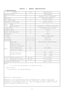


© Copyright 2026