
Best available cop
Oct. 11,1927.
E`.`\c. sci-«INKE
1,644,897
CALCULATING MACHINE
Filed March 31. 1923
6 Sheets-Sheet l
Oct’ u’ 1927’
E. c. scHlNKE
1,644,897
CALCULATING MACHINE
Filed March 31. 1923
6 Sheets-Sheet 2
A Trop/15V;
Oct. 11, 1927.
l,
E. C. SCHINKE
,897
cALcULn-ING MAGHINE
Filed March 31- 1923
6 Sheets-Sheet 3
myn/T01?
E. 6. 50m/rf .
¿Y @mw/mm;
A fr0/Mfrs _
Oct. 11, 1927.
'
E. c. scHlNKE
1,644,897
CALCULÁTING MACHINE
Filed March 31- 1923
6 Sheets-Sheet 4
H6. 1X
zov
3
_
W92
M
>
I
EY MW?
Arrow/5v5
Oct. l1, 1927.
E C SCHINKE
1,644 ’ 897
CALCULATI NG MACHI NE
Filed March 151. 1923
6 Sheets-Sheet 5
_B www@
A rra/m5 Y:
Oct. 11, 1927.
E. C. SCHINKE
CALCULATING MACHINE
Flled March 3l
1923
6 Sheets-Sheet
6
/nvE/vro@
£6.5cH//1KE
BY
Maw/É ¿M67
ArïafP/YEYS
1,644,897
Patented Oct. 1l, i927.
UNITED STATES PATENT OFFICE.
EDV/'ARD C. SCHINKE, OF ‘WEBSTER GROVE-S. MISSOURI. ASSIGNOR TO THE ACCOUNTO
GRAPH COMPANY, 0F ST. LOUÍS. IVIISSOURI. A CORPORATION OF MISSOURI.
CALCULATING IMAOHINE.
Application filed March 31, 13:23.
This invention relates to improvements in . Briefly stated. the preferred form of the
calculating;r machines, and to illustrate cer
tain features of the invention l have shown
5
invention comprises a plurality of accumu
la tors each provided with an‘ actuator in the
form of a .master Wheel, and a denomina
calculatingi mechanism adapted to he actu
ated by the numeral keys and platen car tional carriage movable step by step to si'
riage of an ordinary typewriter. One ot the n'iiiltancoiisly change the denominational re'
objects of the invention is to provide an im
latioii ot' the master wheels to the respective
proved means for actuating and controlling,r accumulators. lVhen all of the accumula
a plurality of accumulators, or totalizers. toisare to be actuated, the denominational
60
The machine herein shown and described carriage locates the master Wheels in their
is provided with a plurality of- accumulators operative positions relative to the‘acc'umu
and each accumulator can be ~selected and lators1 and when only one accumulatoris to
.operated by itself, or two or more accumu» be actuated, the denominational 'carriage-is
lators can be selected and operated at the shifted to locate one of the master Wheels in
15
same time. The selection vof the accumula
tors is preferably under the control of in
65
successive operative positions‘relative' to its
accumulator, While the other master `Wheels
dividual selectors that'can be readily posi are located in successive‘idle positions rela
tioned for the most desirable Aselection of the tive to their accumulators.4 In eitherïf'case
70
accumulators, and the selection will depend the denominational carriage »simultaneoiisly
upon the particular kind of Work to be per
formed by the machine. After being- prop
locates all of the master-'wheels indifferent
positions relative to the accumulators,- so' it
erly'positioned, the selectors automatically is not necessary to. employ morethan'Íone
select the accumulators at the times they are denominational carriage and it .is not neces
75
to be operated, and the> machine preferably sary to provide mechanismfor causing‘onc
includes1 manually operated keys whereby denominational carriage to travel independ
any one or all of the selectors may be ren
dered ineffective.
'
’
=
f
ently
Thisofmaybe
another.
accomplishedby
'
'
.~ ` causing-one
"
The machine about to bevdescribed also
o'f the master wheels to'soccupy- idlepo'si
includes- key-controlledl devices,A :through tions between vdenominational Wheelsgof its
which motion is transmitted foriaddition
accumulator, while I' 'another 'master ~- wheel
and subtraction, and automatic means deter
occupies active positions in meshv with» the
Wheels of its accumulator. By means-‘ofen
mining' whether the operation -is to be addi
tion oi“ subtraction. This automatic means extremely simple selecting device, all of the
is preferably associated with' the selectors master wheels can bei located-in their _opera
80
85
for the accumulators, soI as to predetermine tive positions to simultaneouslyfactuate-the
whether addition or subtraction is. to be per
accumulators. As »an'î illustration of this
formed in the selected- accumulator.
feature of the invention,"I have shown thiny
Each accumulator isîprovided-»with an master wheels adaptedfto idlyßrotate Ibe
90
actuator and a traveling denominational car
tween adjacent denominational wheels of the
riage, movable step by step to change the accumulators, and also adaptedto mesh with
denominational relation of the actuator to the denominational Wheels of~ the accumu
the accumulator, thereby providing for the lators. The means for actuating thetravel
transmission of movement to a series of total ing denominational carriage is .provided
wheels of different orders. The actuator with travelingr selectors wherebyeach accu
95
just referred to ma)v be a. rotary master mulator can be selected and shifted from
Wheel, and it may be carried by thc denomi« an idle position to an active position where
national carriage so :is to advance one step in its denominational vWheels are adapted
in response to cach operation of the- numeral to mesh with one of the mastei' wheels.
licys. In the structure I have shown, the
l/Vith the foregoing and other objects in
denominational carriage is driven by the view, the invention comprises the novel con
travcliï’ig,r platen carriage of an ordinary struction, combination and arrangement of
typewriter.
parts hereinafter morel apeiiih‘cally de~
100
2
1,644,897
scribed and illustrated in the accompanyimY dicated by an accumulator. or l§.=‘\~ a pluralit‘.'
drawings wherein is shown the preferred of accumulatore. Each of the :i:î;'.::a|.iî;rt«=rf;
embodiment ot thep invention. ,Hpwe‘îen _it herein shown comprises a series of «leselam
is to be understood that the‘inyention com riational wheels. or total wheels of (lf-.tl .if
y.
prehends changes, variations and modifica order, and motion is transmitted from :=
tions` which `come within the scope of the master wheel to the total wheels. Eitlv-r
Claire? bereue@ appended.
'
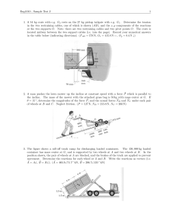
Figl‘f Vis* a side elevation, partly in sec
tion, showing a typewriting machine pro
vided with calculating. mechanism embody
the. master wheel or the accumulator nur:
travel step bj“ step in response to the los);
operations, so as to change the denomina»
tional relation of the master wheel to thc
ingì the features of
accumulator.. r[he master wheel is therefore.
invention,
ig. II is a detail view of parts of~ the splined to a rotary shaft and carried b_v a
means .íerzrshiftìne a. rerersin geen. ‘5;
.master wheel carriage, or denominational
carriage, adapted to travel in unison with
:the platen carriage of ~tl„1e.t_\jpe-writer. The
S0
master wheel is rotated through the. medium
of- the numeral keys' of the typewriter.
"24)
I do not; deem it neceœary to point. out.
all-oft the details of .construetion -of an ac
-'cuiì1ula_tor,-suc_«h devicesbeing- old and well
fknov'îmfin the art,«and no_jclaim ¿is herein
-rmadeffor ari-accumulator per se. To illus
- ;tioefahewiwt»thetelementsf at .thefltear „of «trate-certain features of the invention, I
“have shown in a more. or _less conventional
~manner three accumulators designated A. l’.
and >C wherein items are added and suh
„tions
"1»
tractedl As will be hereinafter described.
l*these accumulators may be actuated simnl~
'
Eig.
@bottom Yìewïqf parts iatîhe Ítaneously, and they may be actuated inde
trQn'tì‘of the maëhìne, shoivingwseme ef» the pendently ofeach ‘other for either addition
elements. ofthe. .accumulator Selectingfmeans -or subtraction.’
'
Fig. X-is an enlarged side elevation, part
-.Each accumulator herein shown comprises
-a housingl slidably mounted on horizontal '
motion is transmitte faomnumexza ,keys to ‘rods '2 at the -front of the machine. Each
the'm‘aster-gwheel shaft.'
f
=`~
t'
housing is provided with total indicatingr
Fig. XI is a perspectivevieiv shoîwing'g,r the wheels 3, (Figs. I, IV and X) which may`
housine‘of one' of the accumulators and‘the be viewed through a sight openingr in the
shifter- for moving the accumulator from an "top of the housing, and transmission wheels;
idle position 'to; an active position. `
`
‘ 4 meshing with the tota! wheels 3 and adapt -
` Fig. XII is a'detail view of the shifter editó be. driven by _a master wheel. 'l`lu
for the reversing gear on thcfmastcr wheel wheels 4 may be terniezl denuniinaiiunui
wheels for they actual-e the total wheels I’.
shaft.
_
i
`
n
'
_' Fig. K_IHis a transveisejsection looking of different denominations. .=\' designati-.a
toward the f‘ront. of ltheinachi'nel andv show the master wheel associated with tln- arru
ing the master wheel 'carriage whereby the mlllator A, and B' designates the master
wheel for >accumulator lì. C’ is the mash-r
master wheels are‘shifted on their shaft..
Fig. XIV is a diagrammatical _view of the wheel of accumulator C. ."tll of the master
tripahle devices whereby the platen carriage wheel:= are splined to a rotary shaft. í». and
is connected to t-he 'means for drix-'ingg- the when in service they travel step hv sich.
master wheel carriage.
'
'
longitudinally of the -.shaft
so af; :u suma-:<
>"Fig, 1_\_V is a fragmentary view of a part sively mesh with the denominational n'herls
o_f'tlie means for disconnecting the calcu 4 in the. accumula-tors. rThe master wheel
latin'g- mechanism from the typewriter keys.
' Y ifrfXVI'i‘s' a diagrannnatical view of the
traveîirig' selectors and tlie‘shifters- actuated
Shaft- 5 is rotated through the medium et'
the numeral keys. as will he luweina'ïter «lz»
Ascribed.
~
The master wheel carriage. or rlenfnnlna
uBwrîietly stated. the machine about to he tional carriage. comprises a traine (ì pro
thereby."
‘
'
A*
'
described isv a- calculating attachment. for vided with fingers 7. eacl‘. of said tinffers~
typewriters. and is'ada'p'ted 4for use with extending into’an annular _groove in the huh
65
ordinary typewriting machines now on the of a master wheel. The traine (5 is provided
marketf The numbers to be added are writ with rollers 8 engaging stationary horizontal
tien by the typewriter and the total is in tracks 9 parallel -with the master wheel shaft
1,644,897
5.
8
It is to be uuderstomll that the master sidered :s one of the. numeral key levers
wheel carriage including fname 6 and fingers with which t-ypewriting machines are ordi
T can he shifted along the' stationary tracks narily equipped, it 'being unnecessary to
change the keyboard of the typewriting mn
chiue used with the calculating attachment. 7o
1ìldrsignatc~z a. lacy lever extension :fl"ig. l)
t) tn locate the master wheels` in different.
positions relative to their aceumulators.
Fue/fing .'Ím 11m-Ste7- 'wheels'.
'l‘ir change the flcuzmzinaîinnal relation of
il'
secured to the numeral key lever 42 and pro
vided with a pin 44 through which motion
the master wlu‘cls to the :i
:nulziîms each is transmitted to the calculating machine.
nl' the master wheels is movable step h_v step -l'laeh numeral key lever is provided with an ‘7'6
extension «13. Vertically guided slide bars
along the master wheel Shaft 5‘ and these
movi-:ments are obtained h_v transmitting ~l5 (Figs- l and lV) are connected by means
power from the platea carriage of the type of levers 46 to the key extensions 43, each
writer tr» tlu: i12-lister vrhL‘el i311’ .. ‘. 'l‘iìc
the upper
levi-1S
end 46of (Fig.
one of
l) the
being
vert-ical
pivoted
slide
to 80
:lzaìstf‘i' WlEL'â‘l lîur‘l‘izagc iS |)1'i='-.'illi'-’l :il tiri ol'Asaid
lnwi‘ì' ezljge willi :i toothed rzl-¿h lll (läge. l hars 4?; and provided at its upperend with
and .-\ll_ii)-u|esl1iug with :t .sector il Iixed to
:i long oscillatornv’slxz:fl. ‘lit which exten-'ls
a{iprmrinmlrli' from the fronti. te: tiut z‘r-:xi‘
«'»tÁ tlu: machine. .-\ sector 2l (l‘ïf's. i and
a hook adapted to receive the piu 44 on one
feeding lever :22, sai-l lever heilig dctacha'oiy
gaged with
of the key extensions 43. These connectinè;levers «t6 are used to transmit power from
vthe numeral keys to the slidehars 45, and 85
Vil) is rigidly secured to the rear end ot' each of said _levers 46 can occupy the opera
the long shaft '20, and :hirz sector ‘il meshes tive position shown by Fim-{,„wherein the
wit-li teeth at the lower edge oi" the loner hook -at the upper end fof 'the lexîeriis en
'
_ levers 4_6pin
canjeton
beshiftedtolìdlel
a. key extension;
positions
or 90
secured to»- the typewriter by means of a said
pivot screw
:wherein _their
`diséiigal?gi'cd from
E designates the platen carriage of the pins «L-ê, so. as _toallow Ythe'~i1uine`ral._keysl-_tîo
Vtypewriter (Fig. I), said carriage being _be operated without
adapted Ito travel back and forth in a to the-„calculating
straight horizontal line, and it_n1_ay._be actu for shiftingfthe leverst‘lç
_x?ov'è'uiein't
v-
i
i
95
fated linresponse to the key operations,-is
_well lundelswod» in this art, 4the carriage
n Ui
moving »one Steppin .response _to _e__'acl'1-A key
operation.,-,:'l`he rene portion of „the platen
Acarriage -is provided .with a. lonn- toothed
horizontal bar ‘24 (Figst- I, V- and
a ber
of this- kindjbein'g present intheczxrriagesof
»severalfweilf known typewriters ¿nowj on the :47': desi «mates
I and
market~._ 1.1i-, KÍ- and di? designate. pinfcarry
ing --clips stmddling'the toothed barV 24 and
adj usta'nly- mounted thereon.. `- Each` of these
-clips. is- provided with-.sr power- transmission
pin-‘25 adapte‘d- to cooperate with Vcertain ele~
ments atgth’e upper end‘of the'long lever 22,
.
i
,
for the purpose 0f îransmittincr movement digit 2 being adapted toïlrixie'saidshaftffl'î 110
from the platen carriage _t.o_ sai( longlever n. distance of two stepsàètegitlie'?l‘këy' being
2? The. fingersat the. uppeirflend o_f__--th_c adapted to drivesáid'shzift nine steps, all
'lever 22 cooperate in a peculiar manner with of which isfwelt understood »in this 'ai-t.l ¿ f _
the pins ‘25 as will he hereinafter described,
To accomplish this, each 'oft-he slide bars
hul. itshouid now be understood that, the 45 representing the digits-_1_tofßhjnclusive, "5
long lever
oscillates ‘in response to move- may be provided with@ predeterminedphurn
ment-s of the platen> carriage, and that. mo her of rack teeth 45f adapted to mesh _with
tion is thus transmitted -from thelong lever a toothed digit. wheel-4S. (Figs._ I, IY and
X), the digitA wheels beingrigidlysecured.
chine, and thesate through the long driving to the digit-wheel shaftî~4î and the racks ’2°
shaft ‘20 (Figs, l and V) to tlielscctor 1l heing- formed on1 the respective slide hars.
"_I‘Z'to the sector '21 at the. rear of the ma
which meshes with-the rack l() on the master 'It will now be understood that thejniuneral
wheel carriage. Motion is thus transmitted keys representing digits'l to 9_, inclusive. are
from the trai-elim?)r platen ~carriage-to the used to actuate slide-*bars 45 whereby/.the
master wheel carriage.
digit wheel shaft 47 ishactuated, and ;the ’25
fimbriae-'fling -:.-1/,=1:cn.ren¿ fro-ni key! levers t0 degree of movementixnparted to -the digit
wheel shaft will depend upon -the value- of
ff'ir, rai/wy master 'ts/zaal shaft.
'l'he key îevez‘ «l2
the key from which motion‘is transmitted.
i) forms part of In Fig. I a screw 27 is located beneath a
thc typen-nung machine, and may be con
slide bar `l5 to limit its downward motion, no
1,644,897
and each slide bar may be provided with
an adjustable stop of this kind.
'l` he means for transmitting movement
from the digit- wheel shaft 47 to the master
wheel shaft 5 is shown most clearly in Figs.
l. IV and X. The digit wheel shaft 47 os
rillates in response to the movements of the
vertical slide bars 45, but the master wheel
shaft 5 is driven continually in only one
10
16
58 pivotally supported at 59 and extendin0r
into an annular groove in the hub of sai
wheel 55.
By operating the lever 58, the
gear 55 can be placed in mesh with -either
the gear wheel 52 for addition or the revers
ing pinion 53 for subtraction. This lever
can be manually operated, and it is operated
automatically as will be hereafter described.
the 'numeral keys from. ¿he
direction during the adding operations. 49 lìisco'n-nece‘i-lig
calculating mechanism..
designates a ratchet wheel fixed to the digit
I have previously referred to connecting
wheel shaft 47, and 50 designates a gear
wheel looselyI mounted on said shaft. A levers 46 (Fig. I) having hooks whereby the
pawl 5l, (Fig. X) engaging the ratchet numeral keys are detachably connected to
wheel 49, is pivotally secured to the gear the calculating mechanism. Each lever 46
wheel 50. The train of gearing through has a depending leg 46’ which extends be
which motion is transmitted comprises a tween a pair of long horizontal rods 64
large gear 52 (Figs. I, IV and X) meshing (Figs. I and IV) secured to oscillatory arms
with the gear wheel 50, a pinion 53 meshing 65. These arms 65 are actuated to move the
zo with the large gear 52` and a shiftable gear levers 46 to connect the calculating mecha
55 adapted to mesh with the pinion 53. for nism to the typewriter, and also to discon
85
subtraction, and also adapted tomesh with nect the calcu ating mechanism when the nu
the gear 52 for addition.'A This -s_hiftable
gear 55 is splined ’_to the master'wheel shaft
5. A pawl 56 (Fig. X) cooperates with the
large gear 52 to prevent :retrograde move
meral keys are to be operated independently
of the calculating mechanism. The arms 65
are fixed to an oscillatory shaft 66 (Figs. I
and XV) provided withan operating arm
90
ment of the train of gearing. This train of G7. A spring 68 (Fig. I) tends to move the
gearing, including the ratchet and pawl 49,
arms 65 toward the front of the machine,
51, transmits rotary movement to the master thereby tending to connect the upper ends
wheel s_haft 5 in response to the oscillatory of levers 46 to the numeral key levers. Note
movements of the digit wheel shaft 47, and that a' roll on the operating arm 67 (Figs.
when the machine is in service, the master I and XV) is adapted to be engaged by the
wheels travel along the shaft 5, ‘advancing top‘face of an arm~69 on the long shaft 20.
step by step from .one accumulator wheel to If the shaft 2O is turned in vone direction, the
as another, so as to successively actuate'the dif
ferent total wheels. For example, to intro
40
arm >69 will move upwardly to impart a
forward movement to the-lower end of arm
duce the numeral 29 into an accumulator, 67, thereby actuating the arms 65 and rods
the 2-key is depressed while the master wheel 64 to disconnect the calculating mechanism
registers with an accumulator wheel 4 in from the numeral keys. If the shaft 2() is
the tens order. The total -wheel in the tens then turned in the opposite direction, it will
order is thus turned 2 steps, and the master lower the arm 69, and thereby permit the
wheel is then driven by the platen carriage spring 68 (Fig. I) to connect the calculat
.so as to pass to the units order. Thereupon` ing mechanism to the key levers as shown in
45
the 9-key is depressed, with the result of
actuating the total wheel in the units order,
driving it nine steps.
Sub traction.
In subtracting one number from another,
the drawings. It will therefore be under
stood that the oscillatory shaft 20, which
transmits movement from the platen car
riage to the master wheel carriage, also
serves as means for connecting and discon
necting the key levers. )Vhcn the platen
carriage of the typewriter reaches a prede
versely to the direction ~in which it is driven termined field, it begins to transmit move
for addition. The relatively wide or thick ment to the long shaft 20 so as to actuatc
reversing pinion 53 (Figs. IV and X) is the. master wheel carriage. and when thf`
there fore permanently in mesh with the gear platen carriage passes from said field it rc
wheel 52 through which motion is transmit leases the shaft 20 and permits thc. latter
tml from the digit wheel shaft to the. mas to he restored by a spring 70 (Figs. lV and
ter wheel shaft, and the shiftable gear wheel XIII) at the master wheel carriage thereby
the master wheel shaft must be rotated re
5:'. ou the master wheel shaft can mesh di
C()
causing the arm 69 to engage and actuate the
rectly with the pinion 53 to subtract nu operating arm 67 so as to disconnect the cal
merals from the accumulator, and said gear culating mechanism from the key levers.
wheel 55 can be located in the position shown The restoring spring 70 is connected to the
master wheel carriage, and said carriage is
in Fig. IV so as to mesh with the wheel 52.
The means for shifting the gear wheel 55 provided with a rack bar l0 meshing with
(rigs. X, XH and Xm’) comprises .e level`
sector ll on the shaft 20.
05
1,644,897
Connecting the platen carriage to the means
for feeding the master wheel carriage.
When the platen- carriage of the type
'.5
XIV and .by dotted lines at the left side of
Fig. XIV. A traveling pin 25 can then pass
the finger 84’ and engage the finger 84 to
transmit motion to the lever 22. At the be
65
writer reaches a predetermined position,> it ginning of this motion, the finger 84’ passes
begins to transmit movement to the means from cam 87’ and its spring 86' then shifts
for feeding the master wheel carriage, and the finger 84’ to a position in alinement with
after the master Wheels pass entirely across the finger 84. The pin 25 then lies between
their accumulators, the feeding means is dis the fingers 84 and 84’ and movement can be
engaged from the ‘platen carriage, permit- transmitted
in either direction from. the
tingr the latter to continue in motion With platen> carriage
the long lever 22 whereby
out advancin thel master Wheel.- I have the master wheelto carriage
is operated.
A'
already brie y described theÍ means for
lVhen
the
master
wheels
travelentirely
transmitting movement from the traveling across their accumulators, the finger 84 is
platen carriage to the traveling master wheel
by the cam 87, as shown by dotted
carriage, and Vattention is -now directed to tripped
line's'at the left side of Fig. XIV,'thereby
the means whereby the platen carriage is permitting thespring 83 to quickly restore
connected to and disconnected from-the long the
lever 22. The pin 25 can then continue
feedinglever 22 at the'rear of the type in motion
with the platen- carriage,-Without
20
writing‘machine.
A
'vf
»
»
-This feeding lever (Figs. I-and V') is in driving the lever 22. 'Thereafteig the other
the form of a. sector meshin With~ the sector traveling pins _25 will cooperate vvith'A the
85
21 at the rear of‘the long s aft 2O through fingers 84 and 84’ in the same mannerltoïac-v
and then release _the long lever 22 'and
which movement is transmit-ted to the mas tnate
the mastenivheel carriage driven j~the'reb .
25
ter wheel carriage'atïthe front 'of -the ma
chine. _The‘ power‘transmission pins 25 se
cu red to the adjustable clips at 'therearvpor
' lVhen t-he platen carriage is eventual y
restored, -the- spring pressed
84'='an'd
84’
will
occupy
the
positions
shown
byl
t-ion'oftheplaten carriage', form parts ofthe lines at the lright side of Fig. XIV,'and full
the
means for connecting said platen carriage traveling pins 2_5 will' engage theinclined
lto the feeding-lever 22j` 83 designates a face ‘of finger'84, so as to shift said finger
restoring spring tendingcto retain the _lever out of the path of the pins.
' " ~
22 in the position shownzby Fig, VI, where
t@ 51
it fengages’fa' -,.stationary `s't'opf-.pin 832:- An
elongated‘tripable abutment finer 84.is piv
otally 'mounted ona. in 85;( igs. Y, VI.
VII and XIV)- carrie by the long lever;22`
the axis- of 'the pivot fbeingiapproximatelv
parallel with the horizontal path .of the
90
95
' .A'utof/mztz'cally.I> .selectingA the'
lVhen'one of the traveling‘pins 25> trans
mits' motion from the platen 'carriageíto the
long'lcver 22, -the master wheel‘carr'ia e is
actuated to simultaneously shift‘allfo -the
master wheels A', B’ and, C’_ along the- ro
platen carriage. - This t'ripable finger 84ex~ tary
shaft 5 to which said wheels are s lined.
100
tends'into the »path'of the :pins 25, so -as to lOiie master Wheel cannot be sliifte ‘inde
transmit movement from said ins Ato the pendently of the'others, and all of the 'mas-
lever 22. As shown- most clearly` in Figs.
\' and-VI` 86 'desifrnates'a spring'tending
to retain the finger 84 in the path of the
traveling pins 25.` 84’ designates a retain
ter wheels are rotated at the same ztime
through the medium of shaft _5 `which is
driven by the numeral keys. However, any
of the arcumulators can be actuated in
ing finger parallel with the fìnger'84 and one
dependently of the others, and any two or
movable into the path of the traveling pins all
three of the accumulators can be actu
25 so as to cooperate with the finger 84 in
at the same time.
"
r‘minet-ting the platen carriage to the long ated
ÍAlthough the three master wheels A’.'_ B’
:10
lever 2L'. 'l‘he linger 84' is supported on the
and C’ travel step b): step at the Same time
pivot 85, and :i spring 86’ (Fig. VI) tends to
mesh with their successive denominational
to retain the upper end of this finger 84’ in
the path of the traveling pins~25. The wheels 4, it will be observed that the space
lingers 84 and 84’ move with' the long lever between any two adjacent wheels 4 (Fig. IV)
22 and they lie between stationary cams 8T is greater than the thickness of a master
and ST’. (Figs. VI and XIV) each finger wheel, and it is possible for a master wheel
having :in inclined edge adapted to engage. to idly rotate in the successive. spaces be
:i correspondingly inclined face on one of tween its denominational wheels 4. ' There
60
the cams. Through the-medium of these fore, the accumnlators are slidably mount
cams. the pivoted fingers 84 and 84’ are ed on horizontal rods 2 parallel with the
shifted laterally to positions beyond the master wheel shaft 5, and each accumulator
path of the pins 25.
_
’
can be shifted a slight distance to the left for
the purpose ot' locating its denominational
ingr position. the fingers 84 and 84’ lie in the wheels 4 in active positions where they will
{.mjsìrinns shown by full lines in Figs. VI and be actuated by their master wheel. If an ac
“'hen the long lever 22 orcupies its start
llU
6
1,644,897
cumulator is permitted to remain in its idle pin 1.03 and provided with operating exten
position, shown Fig. IV, its master wheel sions a, b and c which lic in different planes
will travel step by step. with the other master below the toothed bar 24 on the travelirg
wheels, but-.the master wheel aesociated‘with platen carriage.
Each of the adjustable clips K, K' and
the idle accumulator will rotate idly in the
spaces between vits denominational wheels 4. K2, traveling with the bar 24, is provided
The means for selecting the accumulators with one or more dependingr selectors desig
comprises automatic devices whereby the ac nated by A2, B2 and C2, and shown most
cumulators to be operated are shifte l to the clearly in Fig. XVI. Each of these travel
lett from the positiplls Shown in’Fig. V, and ing selectors is pivoted to one of the clips
the selected accumulators are- thus positioned (Fig. VI) and provided with an upward
'
extension 104 adapted to engage the ~clip to
o,n_ one of _the rods 2 an it is held there b
means ot a @storing spring'Sl (Figs ’IlA I .
and XI) . .Each accumulator is also provided
with .a .Shifter compri-.sing a 1ever92rîv0ted
at 93 and adapted to enga e .an 'abutment
gage and actuate the operating extension _a
of the -bell crank lever 102 associated with ac
for actuation hy their master wheels. '
When an accumulator occupies its idle po` limit the pivotal motion in 'one direction.
Sitten, its housing enseres@ Stop-0611er 90 The travelingr selector Az is adapted to en
I-Sl C
uw ai. (Figs. l, 1V and. fui patted fo‘ ‘one
sie Qta@ ammalata housing. when the
abutment lever.- . 9.2i fil-‘euries the' posit-ion
Sheva in Figs I. and Xl, it iS held in eingege--
cumulator A, so as to shift said accumulator
from its'idle position to its active position.
The selector B2 is adapted to likewise engage
and ac'tuate the operatin extension b as_so
ciated with' ~accumulator , and the selector
C2 is adapted to engage and actuate the ex
tension 'c to 'shift the accumulator C. This
ment :with .a Sten . pin $5 by means' Qf a is suggested by Fig. XVI, wherein the trav
spring 96, and if the shiftingl lever 92 is then cling' selectors moving to the left are ar
Operated. .it will engage the _abutment lever ranged to first select the accumulator A
94. to .shift the açcvmvlater- Herr-ver, each which is operated inde )endently of the other
abutment lever has an extended handle'whieh accumulators,4 this selection being accom
may-.be tdepressed by the operator to locate plished through the medium of selector A2
' said lever below the path of .the -upper end engaging operating extension a to transmit
of ‘the adjacent _shifting lever 92. and in the shifting motion to accumulator A which
this event'thè shifting lever cannot displace lies avt-the tleft, side of the machine. There
the accumulator .from its idle position. Con after, the selectors B2 and C2 carried by clip
sequently, eté-h abutment lever .94 Serves 11S K', engage and actuate the operating exten
' a manually :operable key adapted to prevent sion b ‘and c to shift the middle accumulator
B and the right hand accumulator ‘C2 both
the selection of its accumulator.
‘After an abutment lever 94 has been de of which are then o 'erated independently of
pressed, it is held by _the operator until the accumulator A; an after the opera-tions -in
adjacent shifting lever 92 has been moved these two 'accumulators have been completed,
toward »the RCCumulator, and it can _then be the selector Cz engages operating extension
released and permitted to engage the lower c to provide for independent operation of
edge of the extended upper end of shifting accumulator C. 'It will be apparent that the
lever 92. IVhen the shifting lever is c_ven
selectors can be readily rearranged or modi
abutment lever 94, and the latter will be re
stored by its spring 96.
the accumulators.
tually restored, it will release the depressed fied to provide for any desired selection of
The automatic means for shifting the
levers 92 _to select the accumnlators com
In moving to the lett (Figs. VIL Vlll
and XVI) the selectors actnate the operat
ing extensions while the members 104 are en
prises arms 97 pivoted at 9S and adapted to gaged with the traveling clip? tir. limit the
engage rolls on the lower ends of the respec pivotal motion of the selectors, but. when the
tive shifting levels 92. The means for actu traveling platen carriage is restored by a
ating these arms 97 is shown most clearly by movement in_thc opposite direction, the se
Fig. XVI. Bell crank levers 99, at thc rear lectors idly ride over the operating exten
lower poi-_tion of the machine, _are connected sions a, b and c,- while the extensions 104
bv means of rods 100 to the respective arms move away from the clips.
After an accumulator has heen selected
9i', and to cach bell crank 99 is _connected a
rod 101 extending upwardly therefrom and and shifted. it is loi-lied in its operative posi
having its upper end connected to a bell tion through the medium of a latch member
crank lever 10’2. There arc three of the 105 (Figs. VIII and XVI) . There are three
levers 102, one for cach accumulator, and lat-rh members §05. one for cach accumu
each of these levers 102 can be operated to lator` and cach latch member is pivotcd to
transmit the shiftingT movement whereby its one of the bell crank levers 102 and provided
accumulator is shifted and thus selected for with a shoulder 106 adapted to engage a sta
operation by its master wheel. The three tionary bar 107 to retain the selected accumu
levers 102 are all pivotally supported on a lator in its` operative position. After the
tu)
‘
ltlfi
1,644,897
operation in the selected accumulator has and XU) having t-c-:n notches :zdapäetl to re
been completed, the latch member is released, ceive the lorrc cud ol Said ici-cr.
as will be present.y described, and the ac
¿ cumulator is then shifted to its idle position
.ic :ranas for shii'tin g
_
2_
c
ni: lever
,
ve r
l5 (jig o.
1X :1nd XVI) :_lotted 1.o recois-e the lower
by means of its restoring spring 91.
The means for unlocking the latch bars end of lever 58 and connected h_v neans of
105 (Figs. VI, VII and VIH)- --comprises a.
'
pin 108 carried by _the large oscillatory lever
`
"
~ t. .,.g
:at
70
the
es :z rod
22 through which motion is transmitted from
g
l( lercr 11T to an
the platen carriage to' the master Wheel car arm 119, the latter being pivotcd at. l2() and
75
riage .Upon the completion of a calculating provided at its free end with a roll lili adapt
operation, the pin _108_.engages a cam face ed to be engaged by pins i‘Z-_l and 123 ea'
109 on the bottom o_f the selected latch mem tending rearwz-.rdlr from the iravelin'r clips
ber 105, 'so'.asito lift' said latch member- and
releaïe. its shoulder 10G _from the stationary
ba'rj10fí, ,therebyzrele'çising the selected ac
it, it' und Ka
`
°
rJ'Che traveling pins 122 are positioned to so
ride over the roll 19.1 so as io depress the
cumulator and permitting it to return to its arm 119 (Fig. II) and the pins 123 are posi
idle position- Immediately thereafter, the
85
92 to provide for addition, and when ¿aid
_.:Undensomevgconditions -the pin 108 may arin119 is depressed it moves the shifter
,iailto release the latch member, or members lever to the subtract-ing position. Each oí
_105. ,1For example, thev calculating operation the traveling clips K, K' vand li: carries one
may
completed: and the .operatori may re of the pins 122 or 123, and each of these pins
90
tion _shown
en
tioned to travel under and thereby elevate
largelever 2Q is released from its traveling the arm 119 (Fig. Ill). ~`diiien said arm is
o erating `pin,25 .and-restored to the posi moved upwardly, it actuales the shifter lever
Figs'. VI and VII.
s
store the .platen carriage beforev the _pin 108 may be termed “a selector-’fior the reason
strikes the cam faces VAon the latch member. that it automatically selects either addition
30
Or, .if the .carriage operation is very rapid, or subtraction. This selection is made at
the latchmember may fallback to its locking about the time the master wheel carriage be
position‘after being releasedv by the )in 108. gins its step bjr step motion, and at this time as
Therefore, the unlocking means for t e latch the accun'iulator, or accumulators, are also
members ,preferably includes`> an -addi tional selected.
35
unlocking device whichïbecomes effective
It will be understood that the automat-ic
when the long lever 9.2 is're'stored to the posi selection of the accninulatois, as well :is the _
,tion shown by Figs. VI and VII. Thi-‘s ad automatic selection for addition and sub foo
ditional device is an arm 110 pivoted at 111 traction can be lnodilied it; obtain the :no_t
and having an extension 112 at its free end deìirable results for dií’ferent kinds of worn,
arranged to lie under the endsof the latch
members 105 when the latter occupy their
locking positions. This arm 110 is provided
with an operating linger 113 adapted to be
engaged by pin 10S when long lever 9.2 oc
cupies the starting position shown by Figs.
the traveling clips being adjustable and re
movable, so that they can he readily removed
and rearranged or replaced by clips having
105
the desired selectors thereon. .-\n,\‘ desired
number ot accnmulalors n
he. usen', and
any of the acculntzizzîors het
i .shown can he
Vl and VII. Consequently, when lever
eliminated from the calculating operations
is restored, the pin 108 engages finger 113 by removingr the clip with thc .selector for
to elevate the free end of any latch inein
ber 105 that occupies its locking position.
The latch members can thus be released from
the stationary bar 10i'.
Aulo-matic conf-rol of addílìou and snol/'ao
lion.
that accumulator.
l claim;
l. In a calculating- machine, a plurality of
_accumulators cach provided with a series ol'
toothed denominational wheeis and a tooth
ed rotar_\_- actuator adapted to mesh with
said wheels and also adapted to occupy idle.
l have previously referred lo the gear :35 positions bchveen adjacent denominational
splined to the reversible master wheel shaft wheels.l cach _of the. rotar_v actuators being
and adapted to mesh with gear wheel 52 for movable step by step to mesh with its ditl'cr
60
addition. or reversing pinion 53 for subtrac
tion. The shiftable gear 55 is shifted b_v
mean.: of lever 5S having a pin 58' e.\'tendin«r
into an annular groove in the hub of said
gear. This lever 58 can be operated h_v
12u
cnt denominational wheels and also from «uw
of .said idle positions to another, certain oi
the teeth of said actuators passing through
the Spaces between teeth of said denomina
tional wheels when said actuators pass from 125
hand. and it is also operated automaticallv one idle position to another, and selectors
to provide for the selection of either addi adapted t0 establish an operative relation
tion or subtraction. After being shifted.~ the ship between said actuators and thcirdeaomì
lever 58 is _vieldingly held b_v means of a national wheels. each of said selectors being,
spring actuated detent arm 114 (Figs. 1X associated with one of said accumulators to
1,654,897.
8
control the transmission of movement
thereto.
In a calculating machine, a plurality of
arcumulators each provided with a series
moved from one idle position to another,
key-controlled means whereby said actuator
wheels. cach of the rotary actuators being
is rotated to drive the accumulator while in
mesh with said wheels and -to rotate- inde
pendently' of the accumulator while in said
idle positions, and means whereby said accu»
mulator' is shifted l'rom an active position
wherein said actuator meshes with -the dc
nominational wheels to an idle position’ per
movable step by step to mesh with its difier
mitting independent operation of lthe actua
of toothed denominational wheels and a
toothed rotary actuator adapted to mesh with
said wheels and also adapted to occupy-idle
positions between adjacent denominational
70
ent denominational wheels and also from one tor between said wheels, the last mentioned
of said idle positions to another, certain of means includingr a traveling selector and a
the teeth of said actuators passino' through shifter actuated thereby to shift the accumu
the spaces between teeth of said enomina lator from one of said positions to another.
5. In a calculating machine, a plurality
tional wheels when said actuators pass from
one idle position'to another, a traveling de of accumulatorseach 'having wheels and pro
nominational carriage whereby the step by
Su
vided with an actuator, a traveling denomi
step movement is simultaneously imparted _to national carriage movable 'step by step to
all of said actuators, key-controlled means simultaneously change the denominational
whereby all of said actuators are simultane relation of the actuators to their respective
ou'sly rotated to actuate the' denominational accumulators, each of :said accumulator-s be
wheels in- mesh with an actuator' >while the ing shiftable‘in a straight line from an idle
actuator between adjacent denominational position where all of "its wheels are offset
wheels is idly rotated, and selectors ladapted fro'm its actuator to an active'pòs'itioii where
to establish an operative relationship' be
in one of its wheels _is'in alinement with said
im
tween- said actuators and their denoinination actuator and may be driven thereby, and
al wheels, each of said selectors bein'g asso traveling selectors whereby ~said .accumula
ciated with one of said accumulator-s to pro
vide for independent operation of the se
tors are shifted, each of said selectors be
ing associated with one of said accumulators
:3.9 lected accumulator while the actuator of the to provide for the shifting and'indepen‘dent
other accumulator is idly rotated between operation of the Selected accumulator.
denominational wheels. '
.I
i'
3. In a calculating machine, an accumula
tor provided'with a series of 'toothed denomi
_
_(3. In a calculating machine, a plurality of
aceumulators each provided 'with' a- series
of denominational wheels and a rotary actu
ator 4adapted vto mesh' with ‘said wheels, a
national’wheels arid a toothed rotary actua
tor movable step'by step to mesh with the traveling denominational "carriage movablel
successive denominational wheels, said ac
step by step~ tolsirnultaneously change the
tuator being also: adapted to occup'ylsuc denominational relation- of the actuators to
cess'ive idle' positions between land not in their res ective accumulatols, key-controlled
40
mesh with adjacent denominational wheels, means w iereby said actuators are rotated at
certain of the teeth of said actuator passing the same time to simultaneously actuate the
105
through the spaces between teeth of `said accumulator-s, each of said accuniulators be
denominational wheels when Vsaid actuator ing shiftable in a straight line from an ac
passes from one idle position to another, key tive position wherein one of its denomina
controlled means wherebyfsaid actuator is tional wheels is in alinement with its actua
rotated to drive the accumulator while in tor and may be driven thereby to- an idle
mesh with said wheels and to rotate inde position wherein said actuator is offset- from
pendently of the accumulator while in said said denominational wheels thus permitting
idle positions, and means whereby said Aaccu independent operation of the actuator, and
mulator is shifted from an active position travelingr selectors whereby each accumula
wherein said actuator' meshes with the de tor is selected and shifted from one ut" said
nominational wheels to an idle position per positions to the other.
mitting independent operation of the actua
tor between said wheels.
55
`
4. In a calculatingr machine, an accumula
tor provided with a series of toothed dc
nominational wheels and a toothed rotary ac l
7. In a calculating uuu-hine. a plurality of
:wcnunilators eael'i {_wovìded with a series of
t'lcnominational wheels and a rotary actuator
adapted to mesh with said wheels. a travel
ing denominationz-d carriage movable step by
tuator movable step by step to mesh with step to sin'mltaneously change the denomina
the successive denominational wheels. said tional relation of the actuators to their rc
actuator being also adapted to occupy suc spcctivc accumulator-s. l<e_\_'-c(mtrolled means
65
cessive idle positions between and not in
mesh with adjacent dcnomimltional wheels.
certain of the teeth of said actuator passingr
through the spaces between teeth of said de
nominational wheels when said actuator is
whereby .said actuators arc rotated at the
same time tn simultaneously actuate the ac
cinnulators. cach of said accumulators beingr
shiftablc in a straight line from an active
position wherein one of its denominational
110
1,644,897
9
wheels is in alinement with its actuator and nism comprising two accumulators each
may be driven thereby to an idle position provided with an actuator, a traveling de
wherein said actuator is offset from said de nominational carriage movable ste by step
10
nominational wheels thus permitting inde to simultaneously change the enomina
pendent operation of the actuator, and trar tional relation of both actuators to their ac
eling selectors whereby each accumulator is cumulators, operating means whereby the
selected and shifted from one of said posi step by step motion is transmitted from said
tions to the. other, each of said traveling se platen carriage to said denominational car
lectors being associated with one of said ac riage, one of said accumulators being shift
cumulators to provide for independent op able in a straight line from an active posi
eration of the selected accumulator while all tion wherein one of its denominational
70
wheels is in alinement with its actuator to
an idle position wherein all of its wheels are
8. In a calculating machine a plurality of offset from its actuator and may not be
of‘said actuators are rotated by said key con
trolled means.
20
accumulators each provided with a series of
denominational wheels, a rotary actuator
adapted to mesh with said denominational
wheels and also adapted to rotate between
driven thereby, and a traveling selector
whereby the last mentioned accumulator is
step to simultaneously change the denomina
comprising two accumulators each-provided
tional relation of the actuators to their re
with an actuator, a traveling denominational
shifted from one of said positions to the
other.
1l. The combination of a typewriter having
adjacent denominational wheels, a traveling
denominational carriage movable step by a platen carriage, and calculating mechanism \
spective accumulators, key-controlled means carriage movable step by step to simultane
whereby said actuators are rotated at the ously change the denominational relation of
same time to~simultaneously actuate the ac
both actuators to their accumulators, operat
cumulators, each of said accumulators being ing means whereby the step by step motion is A
30
35
40
45
shiftable in a straight line from an active
position wherein one of its denominational
wheels is in'alinement with its actuator and
may be driven thereby to an idle position
wherein the actuator is voffset from all of
transmitted from said platencarriage to said
denominational carriage, one of said accu
mulators being shiftable in a straight line
from an active position- wherein one of its
denominational wheels‘is in alinement with
said denominational-'wheels whereby Asaid its actuator to an idle `position wherein all
actuator may be idly rotated »between its of its wheels are oil'set from said actuator
denominational wheels, andselectors where and may not be driven thereby,A and a travel
by each accumulator is selected and shifted -ing selector whereby the last mentioned 'ac«
cumulator is shifted'from one of said posi
from one of said posit-ions to the other.
9. In a calculating machine ayplurality of tions to the other, said ï traveling selector
accumulators each provided with a series of being carried by said platen'carriage and
denominational wheels, -a rotary actuator provided with a shift-er through which mo
adapted to mesh with said denominational tion is transmitted from the platen carriage
_
wheels and also adapted to rotate between to the selected accumulator.
12. The combination of a typewriter having
adjacent denominational wheels, a traveling
denominational carriage movable step by a platen carriage and calculating mechanism
105
step to simultaneously change the denomi
comprising two accumulators each provided
national relation of the. actuators to their re
with an actuator, a traveling denominational '
spective accumulators, key-controlled means carriage driven by said platen carriage and
whereby said actuators are rotated at the movable step by' step to simultaneously
same time to simultaneously actuate the ac change tllc denominational relation of both
cumulators, each of said accumulators being actuators to their accumulators. each of said
50
shiftable in a `Ètraig'ht line from an active accumulators being shiftable in a straight
position wherein one of its denominational line from an active position Where-in one of
wheels is in alinement with its actuator and its denominational wheels is in alinement
may be driven thereby to an idle position with its actuator to an idle position wherein
wherein the actuator is offset from all of all of its denominational wheels are offset
55
said denominational wheels and may thus
be idly rotated between said denominational
wheels, and selectors whereby each accumu
lator is selected and shifted from one of said
positions to the other, each of said selectors
from said actuator and may not be'operated
thereby, selectors carried by said platen car
riage` independently movable Shifters adapt
ed to shift the respective accumulators from
one of said positions to the other, and means
being movable step by step in synchronism whereby motion is transmitted from said
with said denominational carriage and pro
vided with a shifter whereby motion is trans
selectors to said shifters` each of said selec
tors being associated with one of the Shifters
to provide for automatic selection of the
mitted _to the selected accumulator.
10. The combination of a typewriter hav» äec'umulatois to be operated.
ing a platen carriage, and calculating mecha-'
13; In a calculating machine; äñ ätctiîrlu»v
1,644,897
lator provided with a. rotary actuator and a from said idle position lo an active position
denominational carriage movable step by wherein one of its wheels is in :iiincincnl
step to change the denominational relation with its actuator axid may be driven in rc
of the actuator to the accumulator, key-con sponse to the movement-s of said actuator
trolled means whereby said actuator is ro and carriage, a traveling selector “hei-cbj.'
tated to actuate the accumulator, said accu said accumulator is automatically shifted
-miilator being adapted to occupy an idle from one of said positions to the other, :i
position wherein its wheels are all offset spring tending to retain said accumulator in
from its actuator thus permitting operation its idle position, a retainingr member cooper
of said actuator and denominational car
ating with said selector to retain the ac«
riage independently of the accumulator, and cumulator in its active position. and auto
said accumulator being shiftable in a straight matic means for releasing said retaining
line laterallytof the machine from said idle member upon the completion of a calculat
position to an active position wherein-one ing operation, said automatic means includ
of its accumulator wheels is in alinement ing a_relea„sing member movable in synchro
with said'actuator and may be driven in nism with said selector and adapted to en
response'to the movements of said actuator gage said retaining member.
16. In a calculating machine, a plurality1
and carriage, a traveling selector whereby
said accumulator is automatically shifted of accumulators each having accumulator
-from one of said positions to the other, and 'Wheels and provided with an actuator,- a
retaining means cooperating with said selec« traveling denominational carriage movable
torto retain the >accumulator in lts active
position.
r
-
'
-
^
14. In a» calculating machine, an accumu
-lator having accumulator wheels and pro
80
85
step by step. to simultaneouslyî change the
denominational relation of the actuators to
their respective accumulators, each of said
accumulators'beingshiftablein a straight line
90
vided with a rotary actuator and a denomi from an idle position wherein its wheels are
national carriage movable step by step to olïset from its actuator to an active position
change the denominational relation of the wherein one of its wheels is in aliiiement
30
40
actuator to the accumulator, key-controlled with its ~actuator and may be driven by said
means' whereby said actuator is 'rotated to actuator, traveling selectors whereby said ac
act-nate the accumulator, said accumulator cumulators are shifted, each of said selectors
beingadapted to occupy an idle‘position being associated `with'one of ~said accumu
wherein its wheels are otfset‘jrom its'actua- Y lators to V-provide 'for the shifting and inde
-tor tlius permitting operation of said actu -pendent operation of'the Selected accumu
ator and denominational carriage independ lator, and latches cooperating `with 'said se»
ently lof .the accumulator, and said accu lectors to retain the selected accumulator in
mulator being -shi?table' in a straight line its active position.
from said idle position to an active position - 17. In aîcalculating machine, a plurality
wherein ‘one of its wheels is in alinement of 'accumulators ~eacli having accumulator
100
with its actuator and may be driven in re wheels and provided iviëh an actuator, a
sponse to the movements of said actuator traveling denominational carriage movable
and carriage, a traveling selector whereby Step by Step to simultaneoueljt1 change the
said accumulator is automatically shifted denominational relation of the actuators to
from one of said positions to the other, a 'their respective accumulatois, each of said
spring tending to retain said accumulator accumulators being shiftable in a straight line
50
in its idle position. a retaining member co
from an idle position wherein all of its
operatingv with said selector to retain the
accumulator in its active position. and auto
matic means for releasing said retaining
member upon the completion of a calculating
wheels are otïset from its actuator to an
operation.
15. In a calculating machine, an accumu
lator having accumulator Wheels and p_ro
vided with a rotary actuator and a denomi
55
active position wherein one of its wheels is
in alinement with its actuator and may be
driven by said actuator, traveling selectors
whereby said accumulators are shifted, each
of said selectors being associated with one of
said accumulators to provide for‘the shift
ing and independent operation of the se
national' carriage movable step by step to lected accumulator, latches cooperating with
change the denominational relation of the said selectors to retain the selected accumu
actuator to the accumulator, key-controlled lators in their active positions, automatic
60
means whereby said actuator is rotated to means for releasing said latches upon the
Actuate the accumulator, said accumulator completion of each calculating operation,
being ada ted to occupy an idle position and springs tending to retain the accumu
wherein alli of its Wheels are offset from its lators in their idle positions.
In testimony that I claim the foregoing I
actuator thus permitting operation of said
hereunto
atliit my signature.
actuator _and denominational carriage inde
pendently of the accumulator, and said ae
EDWARD C. SCHINKE.
cumulator being shi?table in a straight line
125


© Copyright 2026