
User’s Guide Dell™ Cost Effective RAID Controller Model CERC SATA1.5/6ch
Dell™ Cost Effective RAID Controller
User’s Guide
Model CERC SATA1.5/6ch
w w w. d e l l . c o m | s u p p o r t . d e l l . c o m
Notes, Notices, and Cautions
NOTE: A NOTE indicates important information that helps you make better use of your computer.
NOTICE: A NOTICE indicates either potential damage to hardware or loss of data and tells you
how to avoid the problem.
CAUTION: A CAUTION indicates a potential for property damage, personal injury,
or death.
____________________
Information in this document is subject to change without notice.
© 2004 Dell Inc. All rights reserved.
Reproduction in any manner whatsoever without the written permission of Dell Inc. is strictly forbidden.
Trademarks used in this text: Dell, the DELL logo, PowerEdge, and Dell OpenManage are trademarks of Dell Inc. Microsoft,
Windows, Windows NT, and MS-DOS are registered trademarks of Microsoft Corporation. Intel is a registered trademark
of Intel Corporation. Novell and NetWare are registered trademarks of Novell, Inc. Red Hat is a registered trademark of
Red Hat, Inc. SATASelect is a registered trademark of Adaptec, Inc.
Other trademarks and trade names may be used in this document to refer to either the entities claiming the marks and
names or their products. Dell Inc. disclaims any proprietary interest in trademarks and trade names other than its own.
January 2004 P/N P2447
Rev. A00
Contents
1 Introduction
Installation Overview
. . . . . . . . . . . . . . . . . . . . . . .
. . . . . . . . . . . . . . . . .
1-2
. . . . . . . . . . . . . . . . . . . . . .
1-3
Controller Management Utilities
System Requirements .
RAID Controller Features .
. . . . . . . . . . . . . . . . . . . .
1-4
. . . . . . . . . . . . . .
1-4
. . . . . . . . . . . . . . . . . . . . . . . . .
1-5
. . . . . . . . . . . . . . . . . . . . . . . . . . . .
1-5
Advanced RAID Technology Features .
Array Migration .
Hot Spares
1-2
Dedicated Hot Spares
. . . . . . . . . . . . . . . . . . . . .
1-5
. . . . . . . . . . . . . . . . . . . . . .
1-6
. . . . . . . . . . . . . . . . . . . . . . . .
1-6
Global Hot Spares .
Automatic Failover
Audible Alarm Operation
. . . . . . . . . . . . . . . . . . . . .
1-6
Sounding the Alarm
. . . . . . . . . . . . . . . . . . . . . .
1-6
Silencing the Alarm
. . . . . . . . . . . . . . . . . . . . . .
1-7
2 Installing the Controller
Component Layout
. . . . . . . . . . . . . . . . . . . . . . . .
Installation Procedure
. . . . . . . . . . . . . . . . . . . . . .
2-3
. . . . . . . . . . . . . .
2-4
. . . . . . . . . . . . . . . . .
2-4
Checking Your Controller and Devices
Determining the Boot Controller
2-2
Contents
1
3 Installing the Driver
Creating a Driver Diskette .
. . . . . . . . . . . . . . . . . . . .
Installing the Windows Driver .
. . . . . . . . . . . . . . . . . .
3-2
3-2
Installing a Windows Driver During Operating System Installation 3-2
Installing a Windows Driver for a New RAID Controller .
. . . .
3-3
. . . . . . . . . . . . .
3-4
Installing the Red Hat Linux Driver
. . . . . . . . . . . . . . . .
3-4
Creating a Linux Driver Diskette
. . . . . . . . . . . . . . . .
3-5
. . . . . . . . . . . . . . . . . . .
3-5
Updating an Existing Windows Driver
Installing the Linux Driver
Installing The Linux Event Logging Utility
Installing the Novell NetWare Driver
. . . . . . . . . . . .
3-5
. . . . . . . . . . . . . . .
3-6
Installing a Driver for a New Controller .
. . . . . . . . . . . .
Performing a Standard Mode Installation of NetWare 5.1SBE
Updating an Existing Driver
3-7
.
3-7
. . . . . . . . . . . . . . . . . .
3-8
4 BIOS RAID Configuration Utility
Using the Array Configuration Utility .
Creating Arrays
. . . . . . . . . . . . . .
4-3
. . . . . . . . . . . . . . . . . . . . . . . .
4-3
Managing Arrays .
. . . . . . . . . . . . . . . . . . . . . . .
Initializing Disk Drives
. . . . . . . . . . . . . . . . . . . . .
Rescanning Disk Drives .
Using SATASelect
4-8
. . . . . . . . . . . . . . . . . . . .
4-9
. . . . . . . . . . . . . . . . . . . . . . . . .
4-9
SATA Configuration Options
. . . . . . . . . . . . . . . . .
Controller Configuration Options
2
4-5
4-10
. . . . . . . . . . . . . . .
4-10
Using the Disk Utilities
. . . . . . . . . . . . . . . . . . . . .
4-11
Viewing the Event Log .
. . . . . . . . . . . . . . . . . . . . .
4-12
Contents
5 DOS Utilities
Using the DOS Flash Utility .
Overview
. . . . . . . . . . . . . . . . . . .
5-2
. . . . . . . . . . . . . . . . . . . . . . . . . . .
5-2
System Requirements
. . . . . . . . . . . . . . . . . . . . .
Firmware Diskette Kit .
Running the Utility.
. . . . . . . . . . . . . . . . . . . .
5-3
. . . . . . . . . . . . . . . . . . . . . .
5-3
Flashing the Firmware .
Commands.
. . . . . . . . . . . . . . . . . . . .
. . . . . . . . . . . . . . . . . . . . . . . . . .
Error Handling
5-3
. . . . . . . . . . . . . . . . . . . . . . .
Using the CERC Container Configuration Utility
5-5
5-6
5-10
. . . . . . .
5-11
. . . . . . . . . . . . . . .
5-11
Running the CERCCCU
. . . . . . . . . . . . . . . . . . .
5-11
Using Interactive Mode
. . . . . . . . . . . . . . . . . . .
5-12
Interactive Versus Script Mode
Creating an Array with CERCCCU .
Managing Arrays
. . . . . . . . . . . . .
5-12
. . . . . . . . . . . . . . . . . . . . . .
5-14
Using the Scripting Features .
Script File Syntax
. . . . . . . . . . . . . . . .
5-17
. . . . . . . . . . . . . . . . . . . . . .
5-23
Array Definition Block Keywords .
Error Handling
. . . . . . . . . . . . . .
5-24
. . . . . . . . . . . . . . . . . . . . . . .
5-30
Invoking the CERCCCU and Using a Script
. . . . . . . . .
5-32
6 Command Line Interface (CLI)
Terminology
. . . . . . . . . . . . . . . . . . . . . . . . . . . .
Installing the CLI
. . . . . . . . . . . . . . . . . . . . . . . . .
Installing the CLI in Linux .
Accessing the CLI .
6-3
. . . . . . . . . . . . . . . . . .
6-3
. . . . . . . . . . . . . . . . . . . . . . . .
6-4
Accessing the CLI in Linux.
Using the CLI
6-2
. . . . . . . . . . . . . . . . . .
6-4
. . . . . . . . . . . . . . . . . . . . . . . . . . .
6-4
Opening and Closing a Controller.
. . . . . . . . . . . . . . .
6-4
Displaying Information about Your Array
. . . . . . . . . . .
6-5
Managing Failover Options and Hotspares
. . . . . . . . . . .
6-7
. . . . . . . . . . . . . . .
6-8
Displaying Controller Information
Contents
3
Displaying Disk Information
. . . . . . . . . . . . . . . . .
Displaying Array Information .
CLI Command Dictionary
6-12
. . . . . . . . . . . . . . . . . . . .
6-14
General Control Commands .
. . . . . . . . . . . . . . . . .
Container (Array) Commands .
. . . . . . . . . . . . . . . .
6-16
6-27
. . . . . . . . . . . . . . . . . . . . . . .
6-31
Logfile Commands
Task Commands
6-14
. . . . . . . . . . . . . . . . . . . .
Controller Commands .
Disk Commands
6-11
. . . . . . . . . . . . . . . .
. . . . . . . . . . . . . . . . . . . . . .
6-36
. . . . . . . . . . . . . . . . . . . . . . .
6-36
Using Automated Command Scripts .
. . . . . . . . . . . . . .
6-38
A Specifications
B Troubleshooting
Hard Drive In RAID Group Is Missing
Hard Drive Is Off-Line
. . . . . . . . . . . . . . .
B-2
. . . . . . . . . . . . . . . . . . . . . . .
B-3
Controller Not Detected
. . . . . . . . . . . . . . . . . . . . . .
Controller Error Reported
. . . . . . . . . . . . . . . . . . . . .
Controller Rebuild Or Scrub Fails
B-5
. . . . . . . . . . . . . . . . .
B-5
Controller Is Beeping
. . . . . . . . . . . . . . . . . . . . . . .
B-7
No OS Found On Boot
. . . . . . . . . . . . . . . . . . . . . . .
B-7
System Hangs During Controller POST
. . . . . . . . . . . . . .
Unable To Flash The Controller Firmware
. . . . . . . . . . . . .
SATA RAID Disk Set Down Or Array Down Error Reported .
Consistency Check Failed
B-9
B-10
. . . . . . . . . . . . . . . . . . . .
B-11
. . . . . . . . . . . . . . . . . . .
Virtual Disk Format Failed (More Than One Drive?) .
Contents
B-8
. .
Physical Disk Format Failed
4
B-4
. . . . . .
B-12
B-13
Virtual Disk Rebuild Failed
Virtual Disk Failed.
. . . . . . . . . . . . . . . . . . .
B-14
. . . . . . . . . . . . . . . . . . . . . . .
B-15
. . . . . . . . . . . .
B-17
. . . . . . . . . . . . . .
B-18
. . . . . . . . . . . . . . . . . .
B-18
Physical Hard Drive Initialization Failed
Virtual Disk Reconfiguration Failed.
Replacing A Bad Controller .
C Regulatory Notices
FCC Notices (U.S. Only)
. . . . . . . . . . . . . . . . . . . . .
A Notice About Shielded Cables
Class B
. . . . . . . . . . . . . . . .
C-2
. . . . . . . . . . . . . . . . . . . . . . . . . . . .
C-2
IC Notice (Canada Only)
. . . . . . . . . . . . . . . . . . . . .
C-3
. . . . . . . . . .
C-4
. . . . . . . . . . . . . . . . . . . . . . . . . . . . .
C-4
EN 55022 Compliance (Czech Republic Only)
CE Notice
C-2
VCCI Notice (Japan Only).
Class B ITE
. . . . . . . . . . . . . . . . . . . .
C-5
. . . . . . . . . . . . . . . . . . . . . . . . . . . .
C-5
MIC Notice (Republic of Korea Only) .
. . . . . . . . . . . . . .
C-5
Glossary
Index
Figures
Figure 2-1.
Controller Component Layout .
. . . . . . . . .
2-2
Figure 2-2.
Removing the Slot Cover
. . . . . . . . . . . .
2-3
Contents
5
Tables
6
Table 1-1.
Array Migration Possibilities
Table 4-1.
Number of Drives Supported by RAID Level
. .
4-4
Table 5-1.
Number of Drives Supported by RAID Level
. .
5-13
Table 5-2.
CERCCCU Command-Line Switches .
. . . . .
5-18
Table 5-3.
Array Properties
. . . . . . . . . . . . . . .
5-19
Table 5-4.
Array Definition Block Keyword Summary .
Table 5-5.
CERCCCU Error Codes
Table A-1.
Controller Specifications
Contents
. . . . . . . . .
1-5
. .
5-24
. . . . . . . . . . . .
5-30
. . . . . . . . . . .
A-2
1
SECTION 1
Introduction
w w w. d e l l . c o m | s u p p o r t . d e l l . c o m
This document explains how to install your Dell RAID controller, device driver, and
controller management software, which enables you to manage the controller and its
attached storage devices.
Installation Overview
The following steps provide an overview of the process of installing, setting-up, and
configuring the controller:
1
Read and understand this entire section.
2
Install and configure the controller and hard drives according to the instructions in
"Installing the Controller."
3
Install the driver using the generic driver installation guide at support.dell.com. You
will find updated drivers at the same location.
Controller Management Utilities
Your RAID controller includes the following software tools to manage your storage
subsystem:
•
1-2
BIOS RAID Configuration Utility—Part of the controller’s built-in BIOS code. You
start the BIOS RAID Configuration utility by pressing <Ctrl><A> during BIOS
startup. For details, see "BIOS RAID Configuration Utility." The BIOS RAID
Configuration utility contains:
•
Array Configuration Utility—Used to create, configure, and manage arrays. Also
available as a DOS-based executable (CERC Container Configuration Utility).
For details, see "BIOS RAID Configuration Utility."
•
SATASelect®—Used to to verify the hardware configuration of the controller and
the drives.
•
Disk Utilities—Used to format and verify drives.
•
DOS Utilities—Contained on the Dell OpenManage Server Assistant CD.
•
Command Line Interface (CLI)—Enables Linux users to automate array creation or
testing in a production environment using scripts.
•
Storage Management Software Application—If your controller was shipped with a
storage management application, refer to the documentation provided with the
application. The storage management application provides you with an easy-to-use
graphical interface to manage your storage subsystem.
Introduction
System Requirements
•
Dell (or other Intel® based) server or workstation with at least one available universal
PCI slot and a motherboard and BIOS that complies with the PCI Local Bus
Specification, Revision 2.2 and provides large memory-mapped address ranges. Refer
to www.dell.com for computer and RAID controller compatibility information.
•
One of the following:
–
Microsoft® Windows® 2000 Server, Advanced Server and Small Business Server,
Service Pack 3, 4
–
Windows Server 2003, Standard Edition, Enterprise Edition, Small Business
Server and Web Edition
–
Red Hat® Linux Professional, versions 9.0
–
Red Hat Linux Advanced Server, version 2.1, 3.0 32-bit
–
Novell® NetWare®, versions 5.1 and 6.5
–
Novell NetWare Small Business Suite
•
Minimum of 20 MB of disk space for device drivers and storage management software
•
Up to six hard drives (SATA only) and six SATA cables.
•
3.5-inch, 1.44-MB diskette drive
•
CD-ROM drive
Introduction
1-3
w w w. d e l l . c o m | s u p p o r t . d e l l . c o m
RAID Controller Features
The goal of RAID is to provide better performance and reliability from combinations of disk
drives than possible with the same total storage space without RAID.
Your controller supports six SATA drives. The controller offers the features and performance
ideal for high-end workstations and entry-level servers.
•
Conforms with PCI Local Bus Specification, Revision 2.2
•
64-bit, 66-MHz PCI interface compatible with 32-bit/33-MHz PCI slots
•
64 MB of on-board RAM
•
Low-profile, MD2 form factor ideal for 1U/2U servers
•
Supports the SATA Specification, version 1.0
•
RAID levels 0, 1, 5, 10 and simple volume (JBOD)
•
Operating system-independent configuration and RAID creation using the BIOS
RAID Configuration utility
•
Flash ROM for easy upgrades of the controller BIOS and the BIOS RAID
Configuration utility
•
Event logging and broadcasting, including messaging for alphanumeric pagers
•
Audible alarm for data safety. See "Audible Alarm Operation" for details.
Advanced RAID Technology Features
The controller’s RAID features are described below:
1-4
•
Optimized Disk Utilization—Enables you to use the full capacity of all your drives,
even if drive sizes vary.
•
Online Capacity/Volume Expansion—Allows you to expand the capacity of your
RAID during system operation.
•
Online RAID Level Migration—Lets you change RAID levels without rebuilding your
array from scratch.
•
Multiple Arrays—Create multiple arrays from a single set of drives.
•
SATA Disk Hot Plug—If your server supports hot plug, you can add and remove disks
without shutting down your system.
Introduction
Array Migration
The controller supports modifying existing arrays by expansion, migration from one array
type to another, and changing the stripe size, as described by the table below.
Ta b l e 1 - 1 .
Array Migration Possibilities
Current Array Type
New Array Type
RAID 0
RAID 5 or 10
RAID 1
RAID 0 or 5 or 10
RAID 5
RAID 0 or 10
RAID 10
RAID 0 or 5
Windows supports Online Capacity Expansion (OCE). That is, on completion of an array
expansion, the additional capacity can be used without restarting the system. Refer to your
operating system documentation for instructions on using the additional capacity.
Hot Spares
A hot spare is a drive that is reserved to replace a failed drive in a redundant array. In the
event of drive failure, the hot spare replaces the failed drive and the array is rebuilt
automatically. Prior to becoming an array member as a result of a failure, a hot spare can be
unassigned using a management utility.
NOTE: A spare can only be used by the system to rebuild an array if it is the same size
as, or larger than, the failed drive.
The controller supports two types of hot spares:
•
Global—Protects every array that the spare drive has sufficient available capacity to
protect.
•
Dedicated—Protects only the array to which it has been assigned.
Dedicated Hot Spares
When an array member (a drive) containing the dedicated hot spare fails, the spare is
automatically used to store the data contained on the failed drive if the spare has sufficient
capacity. The spare becomes a member of the array with the failed drive and ceases to be
marked as a hot spare. If the spare is much larger that the drive it is replacing, the extra
space is unused.
Introduction
1-5
w w w. d e l l . c o m | s u p p o r t . d e l l . c o m
Global Hot Spares
When an array member (a drive) fails, a global hot spare of sufficient capacity is
automatically used to store the data contained on the failed drive. The behavior of the
system after a failure depends on the size of the spare relative to the drive it is replacing:
•
If the global hot spare is the same size, or less than 100 MB larger than the drive it is
replacing, it becomes a member of the array with the failed drive and ceases to be
marked as a global hot spare.
•
If the global hot spare is larger than the drive it is replacing by 100 MB or more, the
spare replaces the failed drive, yet remains a global hot spare. The unused portion of
the global hot spare is available for use in the event of future failure.
NOTE: In the case of a RAID 10 array, the system can use the same global hot spare
to replace two failed drives in the same array if the global hot spare is at least twice
the size of the failed drives in the array. This is not recommended because redundancy
is compromised. Therefore, when assigning a global hotspare in a system that contains
a RAID 10 array, it is recommended the spare be the same size as the members of the
RAID 10 array.
Automatic Failover
This feature allows the controller to automatically rebuild an array when a failed drive is
replaced with a new drive. This feature applies only to fault tolerant arrays. See "Controller
Configuration Options" for details.
Audible Alarm Operation
The controller is equipped with an audible alarm that can alert you to situations that affect
data safety. You can silence the alarm.
Sounding the Alarm
The alarm sounds under the following circumstances:
1-6
•
When the controller is running, the alarm sounds when any drive fails. For example, if
a drive becomes unplugged, the alarm sounds.
•
When restarting the system, the alarm sounds if an array is degraded. For example, if
a drive is missing from a three-drive RAID 5, the alarms sounds.
Introduction
The alarm sounds if an array can’t be configured. For example, if a drive is missing from a
RAID 0, the alarm does sound. If two drives are missing from a RAID-5, the alarm does
sound.
Silencing the Alarm
Once the alarm is sounding, it continues to sound until one of the following actions is
taken:
•
The array with the failed member is deleted.
•
Redundant array only—A rebuild begins.
•
The alarm is silenced or disabled using one of the following utilities:
–
SATASelect—See the Alarm Control option in "BIOS RAID Configuration
Utility."
–
Array Configuration Utility—See the ALARM= option in of "DOS Utilities."
Introduction
1-7
1-8
Introduction
w w w. d e l l . c o m | s u p p o r t . d e l l . c o m
2
SECTION 2
Installing the
Controller
w w w. d e l l . c o m | s u p p o r t . d e l l . c o m
To install the controller and drives, you need up to six SATA hard disk drives and SATA
cables (supplied in this kit).
Configuration of SATA devices is easy for the following reasons:
•
There are no jumpers or switches to set on the controller or hard drives.
•
The interface cable ends are identical.
•
All interface connectors are keyed so that you can insert them in only one direction.
Component Layout
The RAID controller is shown below. Note the position of the SATA interface connectors
necessary for attaching the SATA hard drives.
ctors
SATA Conne
Port 0
Figure 2-1.
2-2
Port 1
Port 2
Port 3
Port 4
Controller Component Layout
I n s t a l l i n g t h e C o n tr ol l e r
Port 5
Installation Procedure
To install the controller in the system:
1
Shut down your system, disconnect the power cable, and open the system.
2
Identify an unused PCI slot and remove the slot cover, as illustrated below.
Figure 2-2.
Removing the Slot Cover
3
If your system accepts low-profile brackets only, install the low-profile bracket supplied
with your kit in place of the standard full-height bracket.
4
Install the controller in the PCI expansion slot and secure the controller bracket to the
host system.
NOTE: Verify that the card is installed in a PCI expansion slot and that the card is firmly
seated in the expansion-slot connector.
5
If you have not already installed your SATA hard drives, do so now.
6
Use the cables supplied with your kit to connect your controller to the SATA hard
drives.
The cable connectors are all identical, so it does not matter which end you connect to
your controller or hard drive. Also, the connectors are keyed to fit the connector in only
one direction. Do not try to force a cable connector onto the controller or a drive. If
the connector does not slide on easily, try reversing it.
7
Close the system and reattach the power cable.
I ns t a l l i n g t h e C o n t r o l l e r
2-3
w w w. d e l l . c o m | s u p p o r t . d e l l . c o m
Checking Your Controller and Devices
After installing the controller and connecting it to the SATA hard drives, you are ready to
use the BIOS RAID Configuration utility to check your controller and devices, as described
below:
1
Turn on your system.
2
When prompted, start the BIOS RAID Configuration utility by pressing
<Ctrl><A>.
3
If your drives have already been used in another system (even if not part of an array),
select Array Configuration Utility and initialize the drives. If you are not sure if the
drives have been used, we recommend that you still initialize the drives. Otherwise,
skip to the step 4.
NOTE: If a drive appears to be missing, power down the system and check the connections.
4
Select SATASelect® to verify the hardware configuration of the controller and the
drives.
Verify that all drives and controllers are shown. If anything appears to be missing,
power down the system and check the connections.
Determining the Boot Controller
Your controller is bootable. If your system already contains a bootable hard drive with an
installed operating system, you can set up your system to boot a second operating system
from the new controller.
To add a second bootable controller, you may need to use System Setup to change the hard
disk boot sequence so that the Dell CERC SATA1.5/6ch controller is at the top of the list.
If System Setup does not allow this change, your system BIOS may not be configurable to
allow the controller to act as a second boot device.
Refer to your system's "User's Guide" for information about System Setup.
2-4
I n s t a l l i n g t h e C o n tr ol l e r
3
SECTION 3
Installing the Driver
w w w. d e l l . c o m | s u p p o r t . d e l l . c o m
Creating a Driver Diskette
When you install a driver in a new system or update a driver in an existing system, you need
a driver diskette.
You can use the following methods to obtain drivers:
•
Visit the Dell Support website at support.dell.com and download the latest drivers
for your controller. Follow the instructions provided with the download.
•
Use the drivers from the Dell OpenManage Server Assistant CD or other support CD
provided with your server. Refer to Dell OpenManage Server Assistant CD user
documentation for details.
Installing the Windows Driver
This section contains the following procedures for installing the drivers for the Microsoft®
Windows® 2000 Server and Windows Server 2003 operating systems:
•
Installing a Windows Driver During Operating System Installation: Use this method if
you are performing a new installation of the operating system and want to include the
drivers.
•
Installing a Windows Driver for a New RAID Controller: Use this method if the
operating system is already installed, you have installed a RAID controller, and you
want to add the device drivers.
•
Updating an Existing Windows Driver: Use this method if the operating system and
RAID controller are already installed, and you want to update to the latest drivers.
The Windows driver file is available on the Dell OpenManage Server Assistant CD.
Installing a Windows Driver During Operating System Installation
Perform the following steps to install the driver while you are installing the operating
system.
1
Power down the system.
2
Boot the server.
3
During bootup, the BIOS banner should display.
4
Configure the logical drive. See "Using the CERC Container Configuration Utility."
NOTE: If this controller is not your primary controller, you can skip to Step 5 and
configure the logical drives using Dell OpenManage Array Manager (if provided).
3-2
Installing the Driver
5
Insert the Dell OpenManage Server Assistant CD in the CD drive and restart the
server.
6
Select the language that you want to use.
7
Read and accept the software license agreement to continue.
8
Select Click here for Server Setup on the Server Assistant main page.
9
Follow the instructions on the screen to complete setting up the operating system.
Server Assistant detects the devices on your system and then automatically installs
drivers for all of those devices, including your RAID controller.
10
When prompted, insert the operating system CD and follow the instructions on the
screen to complete the installation. Refer to the operating system documentation for
more information.
Installing a Windows Driver for a New RAID Controller
Perform the following steps to configure the driver when you add the RAID controller to a
system that already has Windows installed.
1
Create a driver diskette. See "Creating a Driver Diskette" for details.
2
When the controller is added to a server and the operating system detects the
controller, click Cancel on All Detected Devices and reboot.
3
Install the drivers for the new hardware.
4
The Found New Hardware Wizard screen displays the detected hardware device.
5
Click Next.
6
The screen used to locate the device driver for the hardware device is displayed.
7
Select Search for a suitable driver for my device and click Next.
8
The Locate Driver Files screen is displayed.
9
Insert the driver diskette you created in step 1.
10
Select Floppy disk drives and click Next.
11
The Wizard detects the device driver on the diskette, and the Completing the
upgrade device driver wizard displays the name of the controller.
12
Click Finish to complete the installation.
I n s t a l l i n g t he D r i v e r
3-3
w w w. d e l l . c o m | s u p p o r t . d e l l . c o m
Updating an Existing Windows Driver
To update the existing driver, perform the following operations:
1
Create a driver diskette. See "Creating a Driver Diskette" for details.
2
Insert the driver diskette you created in step 1.
3
Press Start > Settings > Control Panel > System.
The System Properties screen is displayed.
4
Click the Hardware tab.
5
Click the Device Manager.
The Device Manager screen is displayed.
6
Click SCSI and RAID Controllers.
7
Double-click the RAID controller for which you want to update the driver.
8
Click the Driver tab and click Update Driver.
The screen for the Upgrade Device Driver Wizard is displayed. The Wizard helps you
update the driver for the hardware device.
9
Follow the steps in the Wizard to search the diskette for the driver.
10
Select the INF file from the diskette.
11
Click Next and continue the installation steps in the Wizard.
Installing the Red Hat Linux Driver
Use the procedures in this section to install the Red Hat® Linux driver. The driver is
updated frequently. To ensure you have the current version of the driver, download the
updated Red Hat Linux driver from Dell Support at support.dell.com.
If you are installing a more recent driver than the one on the Red Hat CD, you must
download the driver before you begin operating system installation and create a driver
diskette. You will use the driver diskette when you are installing the operating system.
For more detailed installation instructions for Red Hat Linux 8.0 or later, see the operating
system installation guide on the Dell Support site at support.dell.com.
3-4
Installing the Driver
Creating a Linux Driver Diskette
Before beginning the installation, download the driver appropriate for your version of Red
Hat Linux from support.dell.com to your temporary directory. To create a driver diskette:
1
Move the device driver package to your local temporary directory (/tmp) and extract
it as follows:
cd /tmp/
tar -xvzf downloaded-file.tar.gz
2
Insert a DOS- or EXT2-formatted diskette into your floppy drive and extract the driver
file to it as follows:
mount /mnt/floppy
cd /mnt/floppy
tar -xvzf /tmp/driver-disk-file.tar.gz
cd umount /mnt/floppy
NOTE: You can also create a driver diskette using the Dell OpenManage Server
Assistant CD. See "Creating a Driver Diskette" for details.
Installing the Linux Driver
Perform the steps below to install Red Hat Linux 8.0 or later and the appropriate RAID
drivers.
1
Create a driver diskette. See "Creating a Linux Driver Diskette" for details.
2
Boot normally from the Red Hat Linux installation CD.
3
At the command prompt, type linux dd.
4
When the install prompts for a driver diskette, insert the diskette you created in step 1
and press <Enter>.
5
Complete the installation as directed by the installation program.
Installing The Linux Event Logging Utility
If your controller did not come with a storage management software application, you may
want to install the Linux Event Logging utility to log event messages in your Linux
environment.
I n s t a l l i n g t he D r i v e r
3-5
w w w. d e l l . c o m | s u p p o r t . d e l l . c o m
To Install The Utility
Install (as root user):
rpm --install aeventd-*.i386.rpm
Make sure that the previous package is uninstalled. Currently -force may be used either
to get around a previously installed package, or any errant package dependency issues (the
forced package will endeavor to self-compile from the embedded sources to get around
package dependency problems).
To Uninstall The Utility
Uninstall (as root user):
rpm -e aventd
The package posts events to the syslogd daemon as kernel.info, kernel.medium,
kernel.high, daemon.default to syslogd, depending on the priority of the message.
These messages, in a typically configured system (see syslogd and syslog.conf
documentation for the specific machine) will land in /var/log/messages. The
language selected for the printout comes from the system environment (RC_LANG or
LANG).
Installing the Novell NetWare Driver
This section contains the following procedures for installing the drivers for the Novell®
NetWare® operating systems:
•
During Operating System Installation—Use this method if you are performing a new
installation of Novell NetWare using Dell Server Assistant and want to include the
drivers. See "Installing a Windows Driver During Operating System Installation" in
"Installing the Windows Driver" for more information. (Operating system and driver
installation workflow on Server Assistant is the same for all operating systems.)
NOTE: For information about installing drivers if you use the NetWare CD to install your
operating system, see your Novell documentation.
3-6
•
Installing a Driver for a New Controller—Use this method if Novell NetWare is
already installed and you want to add the device drivers after installing the RAID
controller.
•
Performing a Standard Mode Installation of NetWare 5.1SBE—With standard mode
installation, you accept the defaults for the components to be installed.
Installing the Driver
•
Updating an Existing Driver—Use this method if Novell NetWare and the RAID
controller are already installed, and you want to update to the latest drivers for the
controller.
Installing a Driver for a New Controller
Perform the following steps to add a NetWare 5.1 or later driver to an existing installation.
1
Create a driver diskette. See "Creating a Driver Diskette" for details.
2
At the root prompt, type nwconfig and press <Enter>.
The Installation Options screen is displayed.
3
Select Configure Disk and Storage Device Options, then press <Enter>.
4
Select Discover and load an additional driver.
The system detects the extra unit.
5
At the prompt to select a driver from the list, press <Insert> to insert the driver.
Your installation is complete. Proceed to step 6 only if you want to select an additional
driver.
6
Select Select an additional driver.
The Select a Driver screen is displayed.
7
Press <Insert> and read the instructions that are displayed.
8
Insert the driver diskette you created in step 1 and press <Enter>.
The system detects a driver and installs it.
Performing a Standard Mode Installation of NetWare 5.1SBE
Standard mode means that you accept the defaults for the components to be installed.
Perform the following steps for a standard mode installation on NetWare 5.1SBE.
1
Create a driver diskette. See "Creating a Driver Diskette" for details.
1
Select Standard Installation.
2
Type the NDS information, then click Next.
3
Select the correct time zone, then click Next.
I n s t a l l i n g t he D r i v e r
3-7
w w w. d e l l . c o m | s u p p o r t . d e l l . c o m
4
When prompted for a license diskette, insert the License Diskette and press
<Enter>.
The installation screen appears. It displays a list of devices, including Storage Devices.
5
Press <Esc> to display another list of devices, including Storage Adapters.
6
Select Modify.
7
Scroll down to Storage Adapters and press <Enter>.
8
Insert the driver diskette you created in step 1.
9
Press <Insert> to add a driver.
10
Press <Insert> again to make an addition to the driver list.
11
Once driver installation is complete, press <Esc> to return to the main menu.
12
Select Continue and press <Enter> to continue system installation.
Updating an Existing Driver
Perform the following steps to update an existing driver for NetWare:
1
Create a driver diskette. See "Creating a Driver Diskette" for details.
2
Type nwconfig at the system prompt.
3
Press <Enter> to access the NetWare Configuration Utility.
4
On the Configuration Options screen, select Driver Options and press <Enter>.
5
In the Driver Options menu, select Configure Disk and Storage Options, then press
<Enter>.
6
Under the Additional Driver Actions menu, press the down arrow key to select the
Additional Driver option, then press <Enter>.
7
Press <Insert> to install an unlisted driver.
8
Press <F3> to specify a different path.
9
Insert the driver diskette you created in step 1 and press <Enter>.
The file CERCSR6.HAM is displayed under the option Select a Driver to Install.
3-8
10
Highlight CERCSR6.HAM and press <Enter>.
11
Select Yes to copy CERCSR6.HAM files to C:\NWSERVER.
12
Select No to save the existing file messages to C:\NWSERVER.
Installing the Driver
13
Under CERCSR6 Parameters, perform the following steps to provide the slot number.
14
Press <Alt><Esc> to access the System Console.
15
On the System Console, type load CERCSR6, then press <Enter>.
Supported slot options are displayed, for example:
–
No Selection
–
PCI Slot_2.1 (HIN 203)
16
Write down the number after "HIN"; in the example in step 15, the value is 203.
17
Under Choice, type 0 for the option No Selection.
18
Press <Alt><Esc> until you exit the System Console and return to the CERCSR6
Parameters screen.
19
Under Slot Number, enter the slot number you obtained from System Console and
press <Enter>.
20
Press <F10> to save the CERCSR6 parameters.
21
Under Driver CERCSR6 Parameters Actions, select Save Parameters and Load
Driver and press <Enter>.
22
Select No when asked to load additional drivers.
23
The Selected Disk Driver screen lists CERCSR6.
24
Exit the NetWare Installation Utility.
25
Power down and reboot your server.
I n s t a l l i n g t he D r i v e r
3-9
3-10
Installing the Driver
w w w. d e l l . c o m | s u p p o r t . d e l l . c o m
4
SECTION 4
BIOS RAID
Configuration Utility
w w w. d e l l . c o m | s u p p o r t . d e l l . c o m
The BIOS RAID Configuration utility is an embedded BIOS utility that includes:
•
Array Configuration Utility—Used to create, configure, and manage arrays. Also used
to initialize and rescan drives. (Also available as a stand-alone DOS utility as described
in "Using the CERC Container Configuration Utility.")
•
SATASelect®—Used to change device and controller settings.
•
Disk Utilities—Used to format or verify media.
To run the utility, press <Ctrl><A> when prompted by the following message during
system startup:
Press <Ctrl><A> for BIOS RAID Configuration Utility
The BIOS RAID Configuration menu appears, presenting the following options:
•
Array Configuration Utility
•
SATASelect Utility
•
Disk Utilities
To select an option from this menu, or from any of the menus within the utility, browse
with the arrow keys, then press <Enter>. In some cases, selecting an option displays
another menu. To return to the previous menu at any time, press <Esc>.
The following sections discuss each of these menu options.
4-2
BIOS RAID Configuration Utility
Using the Array Configuration Utility
The Array Configuration Utility enables you to manage, create, and delete arrays from the
controller’s BIOS. You can also initialize and rescan drives.
You can use the Array Configuration Utility to create a bootable array for the system. We
recommend that you configure the system to boot from an array instead of a single disk to
take advantage of the redundancy and performance features of arrays. For details, see
"Making an Array Bootable."
Creating Arrays
Before creating arrays, make sure the disks for the array are connected and installed in your
system. For information on how to initialize a disk drive, see "Initializing Disk Drives."
NOTE: Any disks with MS-DOS ® partitions, disks with no usable space, or disks that
are uninitialized appear dimmed and cannot be used for creating a new array.
To create an array:
1
Shut down and restart the system.
2
At the BIOS prompt, press <Ctrl><A>.
3
From the BIOS RAID Configuration utility menu, select Array Configuration
Utility.
4
From the Array Configuration Utility menu, select Create Array.
5
Select the disks for the new array, then press Insert.
The Array Configuration Utility displays the largest usable space available for each
disk. You can use available space from multiple disks for the new array.
To deselect any disk, highlight the disk, then press Delete.
6
Press <Enter> when all disks for the new array are selected.
The Array Properties menu is displayed.
After you install a controller in a system and start it for the first time, the BIOS announces
the configuration it has detected. This configuration may not match your system’s
configuration.
NOTICE: If you do not take any action within 30 seconds, the system automatically accepts the
configuration. If the configuration does not match your system, reject it or start the BIOS
RAID Configuration utility. Otherwise, the array configuration may be erased.
BIOS RAID Conf iguration Utility
4-3
w w w. d e l l . c o m | s u p p o r t . d e l l . c o m
If necessary, start the BIOS RAID Configuration utility. Upon starting the BIOS RAID
Configuration utility, accept the configuration that the utility reports, then modify the
configuration to suit your needs.
Assigning Array Properties
You can use the Array Configuration Utility to assign array properties only prior to array
creation. To assign properties to the new array:
1
From the Array Properties menu, select an array type, then press <Enter>.
The display shows only the array types available for the number of drives selected. The
maximum number of drives allowed and minimum number of drives required depends
on the RAID level, as described in the table below.
Ta b l e 4 - 1 .
Number of Drives Supported by RAID Level
Number of Drives
Maximum
Supported
Minimum
Required
Simple Volume (JBOD)
6
1
RAID 0
6
1
RAID 1
2
2
RAID 5
6
3
RAID 10
6
4
Array Type
2
Type in an optional label for the array, then press <Enter>.
3
Type the desired array size.
The maximum array size available based on the segments you selected is displayed
automatically. If you want to designate a different array size, type the desired array size
and select MB (megabytes), GB (gigabytes), or TB (terabytes) from the drop-down
list. If the available space from the selected segments is greater than the size you
specify, the remaining space is available for use in other arrays.
4-4
4
Select the desired stripe size. The allowable stripe sizes are 16, 32, and 64 KB (the
default). The default stripe size provides the best overall performance in most network
environments.
5
Specify whether you want to enable read and write caching for the array. When
Enabled (the default), caching is enabled, providing maximum performance. When
Disabled, caching is disabled.
BIOS RAID Configuration Utility
NOTICE: When caching is Enabled, there is a potential for data loss or corruption during a
power failure.
Caching should usually be enabled to optimize performance, unless your data is highly
sensitive, or unless your application performs completely random reads, which is
unlikely.
6
From Create array via, select Build/Verify, Clear, or Quick Init (for RAID 1, 5, and
10).
7
For RAID 1, 5 and 10, specify the rebuild rate, one of the following:
8
–
High—Task is high priority, 0 ms delay
–
Medium—Task is medium priority, 50 ms delay
–
Low—Task is low priority, 100 ms delay.
Specify whether you want to enable write caching for the array. When you are finished,
select Done.
Managing Arrays
Use the Manage Arrays option to view array properties and members, make an array the
boot array, manage failover assignments, and delete arrays. The following sections describe
these operations in greater detail.
Viewing Array Properties
To view the properties of an existing array:
1
From the Array Configuration Utility menu, select Manage Arrays.
2
From the List of Arrays dialog box, select the array about which you want more
information, then press <Enter>.
–
Single Level Arrays Only—For RAID levels 0, 1, and 5, the Array Properties dialog
box shows detailed information on the array physical disks.
–
Dual-Level Arrays—For RAID 10s, to view detailed information on the array
physical disks, highlight the displayed member, then press <Enter> to display the
second level. Press <Enter> again to display the physical disks associated with the
array.
NOTE: A failed drive is displayed in a different text color.
3
Press Esc to return to the previous menu.
BIOS RAID Conf iguration Utility
4-5
w w w. d e l l . c o m | s u p p o r t . d e l l . c o m
Making an Array Bootable
You can make an array bootable so that the system boots from the array instead of from a
stand-alone (single) disk. To make an array bootable:
1
From the Array Configuration Utility menu, select Manage Arrays.
2
Select the array you want to make bootable, then press <Ctrl><B>. This changes
the selected array’s number to 00, making it the controller’s boot array.
3
Restart the system.
Whenever making an array bootable, consider the following guidelines:
4-6
•
If the controller is not a boot device, you can disable its runtime BIOS, see "Controller
Configuration Options." When the BIOS is disabled, it does not occupy any of the
expansion ROM region of the system’s memory map. In a system with several
expansion ROMs, disabling the BIOS may be helpful.
•
You cannot make a non-00 array bootable while the array is in a build/verify or
reconfiguration process.
•
The controller always uses the lowest numbered array as its bootable array. If you
delete Array 00 for any reason, the next lowest numbered array becomes the bootable
array. Use the <Ctrl><B> option to mark the correct array as the bootable array (by
making it Array 00).
•
If you want to boot from a stand-alone (single) disk drive, first create a volume on that
disk.
•
The system BIOS provides additional tools to modify the boot order. For more
information, refer to your system documentation.
BIOS RAID Configuration Utility
Deleting Arrays
NOTICE: Back up the data on an array before you delete it. When you delete the array, you
loose all data on the array. You cannot restore deleted arrays.
To delete an existing array:
1
From the Array Configuration Utility menu, select Manage Arrays.
2
Select the array you wish to delete, then press Delete.
3
From the Array Properties dialog box, press Delete again, then press <Enter>.
A warning message is displayed regarding data loss.
4
Select Yes to delete the array, or No to return to the previous menu.
5
At the Array Properties dialog box, select Delete again, then press <Enter>.
6
Press Esc to return to the previous menu.
Managing Failover Drive Assignments
To assign a global or dedicated hot spare drive to an array:
1
From the Array Configuration Utility menu, select Manage Arrays.
2
From the List of Arrays dialog box, select the array to which you want to assign a hot
spare, then press <Ctrl><S> for dedicated hot spare or <Ctrl><G> for global hot
spare.
The Hotspare Management for Array dialog box is displayed, which shows the drives
that can be assigned as hot spare drives.
3
Select a drive, then press Insert to assign the drive as a hot spare.
The specified drive is displayed in the Assigned Hotspare Drives list.
4
Press <Enter> to save the hot spare drive assignment.
A message is displayed asking you whether you have finished managing hot spare
drives.
5
Press Y (for yes) to return to the Array Configuration Utility menu.
BIOS RAID Conf iguration Utility
4-7
w w w. d e l l . c o m | s u p p o r t . d e l l . c o m
To remove an assigned global or dedicated hot spare drive from an array:
1
From the Array Configuration Utility menu, select Manage Arrays.
2
From the List of Arrays dialog box, select the array from which you want to remove the
assigned hot spare drive, then press <Ctrl><S> or <Ctrl><G>.
The Hotspare Management for Array dialog box is displayed, which shows a list of
drives that can be assigned as hot spares and a list of drives that are assigned as hot
spares.
3
From the Assigned Hotspare Drives list, select the drive to be removed, then press
Delete.
The specified drive is displayed in the Select Hotspare Drives list.
4
Press <Enter> to save the removed hot spare drive assignment.
A message is displayed asking you whether you have finished managing hot spare
drives.
5
Press Y (for yes) to return to the Array Configuration Utility menu.
Initializing Disk Drives
If an installed disk does not appear in the disk selection list for creating a new array or if it
appears grayed out, you need to initialize it before you can use it as part of an array.
NOTICE: Initializing a disk overwrites the partition table on the disk and makes any data on
the disk inaccessible. If the drive is used in an array, you may not be able to use the array again.
Do not initialize a disk that is part of a boot array. The boot array is the lowest numbered array
(normally 00) in the List of Arrays dialog box. (See "Viewing Array Properties" for information
on determining which disks are associated with a particular array.)
To initialize drives:
4-8
1
At the BIOS prompt, press <Ctrl><A>.
2
From the BIOS RAID Configuration utility menu, select Array Configuration
Utility.
3
Select Initialize Drives.
4
Browse with the arrow keys to highlight the disk you wish to initialize, then press
Insert.
5
Repeat step 5 until all the drives to be initialized are selected.
6
Press <Enter>.
BIOS RAID Configuration Utility
7
Read the warning message, ensure that you have selected the correct disk drives to
initialize, then press Y to continue.
Rescanning Disk Drives
To rescan the drives connected to the controller:
1
At the BIOS prompt, press <Ctrl><A>.
2
From the BIOS RAID Configuration utility menu, select Array Configuration
Utility.
3
Select Rescan Drives.
Using SATASelect
SATASelect enables you to change device and controller settings without opening the
system or handling the card. With this utility, you can modify the Channel Interface
Definitions and Device Configuration Options.
To access SATASelect:
1
When you turn on or restart your system, press <Ctrl><A> to access the BIOS
RAID Configuration utility when you see the following message:
Press <Ctrl><A> for BIOS RAID Configuration Utility
2
If multiple controllers are installed, select the controller you want to configure, then
press <Enter>.
3
From the BIOS RAID Configuration utility menu, select SATASelect Utility.
The SATA Configuration and Controller Configuration menu options are displayed.
See "SATA Configuration Options" and "Controller Configuration Options" for
details.
To select a SATASelect menu option, browse with the arrow keys to the option, then
press <Enter>. In some cases, selecting an option displays another menu. You can
return to the previous menu at any time by pressing Esc.
BIOS RAID Conf iguration Utility
4-9
w w w. d e l l . c o m | s u p p o r t . d e l l . c o m
To restore the original SATASelect default values, press F6 from the Configure/View
Host Adapter Settings screen.
4
To exit SATASelect, press Esc until a message prompts you to exit. (If you changed any
host adapter settings, you are prompted to save the changes before you exit.) Select
Yes to exit and restart the system. Any changes you made take effect after the system
boots.
SATA Configuration Options
The SATA configuration options are described below:
•
Write Cache (Default: Enabled)—When Write Cache is Enabled, performance is
maximized.
NOTICE: When Write Cache is Enabled, there is a potential for data loss or corruption during
a power failure.
•
DMA (Default: Enabled)—When Enabled, Direct Memory Access (DMA) mode is
used for the drive, providing maximum performance.
•
SMART (Default: Enabled)—Controls the predictive failure feature of the disk drive.
When Enabled and the drive supports Self-Monitoring, Analysis and Reporting
Technology (SMART) configuration, the SMART status of the drive (Healthy or
Failed) is displayed along with the physical drive display during POST. Messages are
logged to the storage management software log file when they occur. When Event
Broadcasting is installed on your operating system, SMART events are also sent to
destinations according to your system’s particular configuration (for example, system
log file, Event Viewer, pop ups, email, etc.) When Disabled, or when the drive does not
support SMART, the SMART status is not displayed.
•
Allow Read Ahead (Default: Enabled)—When Enabled, the drive’s read ahead cache
algorithm is use, providing maximum performance under most circumstances.
Controller Configuration Options
The controller configuration options are described below:
4-10
•
Runtime BIOS (Default: Enabled)—When Enabled, the controller BIOS allows the
controller to act as a bootable device. Disabling the BIOS allows another suitable
controller to act as the boot device.
•
Automatic Failover (Default: Enabled)—When Enabled, the controller automatically
rebuilds an array when the failed drive is replaced. When disabled, the array must be
rebuilt manually.
BIOS RAID Configuration Utility
•
Array Background Consistency Check (Default: Disabled)—When Enabled, the
controller continuously performs a verification on a redundant array to data integrity.
In the case of RAID 1 or 10, consistency checks assure that the data between like
blocks match. In the case of a RAID 5, consistency checks assure that data in the stripe
and the calculated parity for the stripe match. Consistency checking processes reduce
performance. For a RAID 5, the performance reduction is significant.
•
Array-based BBS Support (Default: Disabled)—When Enabled in systems that
support BBS, the controller presents attached bootable devices up to the host system's
BIOS for boot device selection. This is relevant for logical arrays.
•
Physical Drives Display during POST (Default: Enabled)—When Enabled, attached
physical devices are displayed during system POST. Displaying the devices adds a few
seconds to the overall POST time.
•
30-Second Configuration Change Timeout (Default: Disabled)—When Enabled, and
a configuration change has been detected, a message is displayed when the system is
restarted (after controller POST). When you see this message, you can either press
<Enter> to proceed with the restart, press <Ctrl><A> to enter the BIOS utility, or
allow the system to proceed with the restart after a 30-second delay. When Disabled,
you must either press <Enter> to proceed with the restart or <Ctrl><A> to enter
the BIOS utility; otherwise, the system waits indefinitely.
•
Alarm Control (Default: Enabled)—When Enabled, the alarm sounds when a drive
fails or the state of an array changes. (See "Audible Alarm Operation" for details).
Choose Silence to silence the alarm for the current event (if any)without preventing
the alarm from sounding during a future event. Choose Disabled to silence the alarm
for the current event (if any)and prevent the alarm from sounding during a future
event.
Using the Disk Utilities
The disk utilities enable you to low-level format or verify the media of your SATA hard
disks. To access the disk utilities:
1
Turn on your system, then press <Ctrl><A> when prompted to access the BIOS
RAID Configuration utility.
2
If multiple controllers are installed, select the controller you want to configure, then
press <Enter>.
3
From the BIOS RAID Configuration utility menu, select Disk Utilities.
BIOS RAID Conf iguration Utility
4-11
w w w. d e l l . c o m | s u p p o r t . d e l l . c o m
4
Select the desired disk, then press <Enter>.
You are offered the following options:
•
Format Disk—Simulates a format of the hard drive by removing the file system
and writing zeros to the entire disk. SATA drives are formatted at the factory and
do not need to be formatted again.
NOTICE: Formatting destroys all data on the drive. Be sure to back up your data before
performing this operation.
•
Verify Disk Media—Scans the media of a disk drive for defects. Any errors found
are corrected.
Viewing the Event Log
The BIOS-based event log stores all firmware events (configuration changes, array creation,
boot activity, and so on).
The event log has a fixed size. Once full, old events are flushed as new events are stored.
Also, the log is volatile; therefore, it is cleared after each system restart.
To access the event log:
1
When you turn on or restart your system, press <Ctrl><A> to access the BIOS
RAID Configuration utility when prompted by the following message:
Press <Ctrl><A> for BIOS RAID Configuration Utility
2
If multiple controllers are installed, select the controller you want to configure, then
press <Enter>.
3
From the BIOS RAID Configuration utility menu, press <Ctrl><P>.
The Controller Service menu appears.
4
Select Controller Log Information, then press <Enter>.
The current log is displayed.
4-12
BIOS RAID Configuration Utility
5
SECTION 5
DOS Utilities
w w w. d e l l . c o m | s u p p o r t . d e l l . c o m
Using the DOS Flash Utility
The DOS Flash Utility is used to update the flash EEPROM components on one or more
RAID controllers. The utility can also be used to verify a controller’s current flash contents
against the flash images in a specified file or to save a controller’s current flash contents to a
file.
Your RAID controller uses nonvolatile flash to store on-board software, such as BIOS,
microprocessor kernel, and monitor. Whenever it becomes necessary to update any of those
components you can update your controller’s flash components using the utility.
The utility updates the controller’s flash by reading flash image data from a supplied User
Flash Image (UFI) file and writing it to the controller’s flash components. A UFI file
contains all of a controller’s flash images, as well as information about each image. It also
includes general controller information, such as controller type, to ensure that utility uses
the correct UFI file when updating the controller’s flash.
Overview
The utility performs the following primary functions:
•
Update—Updates all the flash components on a controller with the flash image data
from a UFI file.
•
Save—Reads the contents of a controller’s flash components and saves the data to a
UFI file. This enables you to later restore a controller’s flash to its previous contents
should the need arise.
•
Verify—Reads the contents of a controller’s flash components and compares it to the
contents of the specified flash image file.
•
Version—Displays version information about a controller’s flash components.
•
List—Lists all the supported controllers detected in your system.
See "Running the Utility" for command details.
5-2
D OS U t i l it i es
System Requirements
The requirements for the utility are as follows:
•
Runs in MS–DOS, Version 5.0 or later. (You must shut down your operating system and
reboot to DOS. To start MS–DOS, boot from a bootable MS-DOS diskette or from a
DOS partition on a bootable drive. You cannot use a DOS command prompt window
in Windows. )
•
At least 8 MB of extended memory.
•
DOS extenders, such as EMM386.SYS and DOS4GW, are not supported.
The utility supports HIMEM.SYS and is compatible with other DOS drivers running
under HIMEM.SYS (for example, SMARTDRV.SYS and SETVER.SYS).
•
Run from a partition on a drive or array attached to the controller you are updating.
Once the flash update begins, no I/O is possible to any array attached to that controller
until the flash operation is completed and the system is restarted.
•
To update multiple controllers in the same system, first update the boot controller’s
flash, then restart the system, and finally update the flash for any remaining
controllers.
Firmware Diskette Kit
The Dell OpenManage Server Assistant CD includes the executable afu.exe, the
corresponding documentation, and a separate flash image. The flash image may be
comprised of multiple UFI files.
To create a controller firmware kit on diskettes:
1
Locate the firmware package on the Dell OpenManage Server Assistant CD.
2
Execute the exe file and follow instructions to create a bootable MS-DOS® diskette
and the firmware image diskette.
Running the Utility
You can run the utility from its graphical user interface (GUI) or from the command line.
Accessing the Utility from the GUI
To access the utility:
1
At the DOS command prompt (typically A:\>), type afu with no arguments.
The main menu to the utility is displayed.
D O S U t il i t ie s
5-3
w w w. d e l l . c o m | s u p p o r t . d e l l . c o m
2
Select Select Controllers and select the controllers to be flashed.
3
Select Select an Operation.
4
Select any available function and follow the on-screen instructions.
Accessing the Utility from the Command Line
At the DOS command prompt (typically A:\>), type afu followed by a command and any
optional switches. The utility processes the command, prompts you to insert additional
diskettes as needed, exits, and reports success or an error message code.
The syntax of the command line is as follows:
afu <Command> [/C<Controller ID>] [/D <UFI File Path>] [/?]
where <Command> is one of the following commands:
•
help—Displays help text.
•
list—Lists the supported controllers installed on this system.
•
save—Saves the contents of a controller’s flash to the specified UFI file.
•
update—Updates a controller’s flash from the data in the specified UFI file.
•
verify—Compare the controller’s current flash to the specified UFI file.
•
version—Displays the controller’s current flash version information.
The switches are as follows:
•
/C <Controller ID> is one or more controller IDs representing the set of controllers
on which to perform the specified command. You can specify a single controller ID, for
example:
/C 0
multiple IDs separated by commas, for example:
/C 0,2
or all to indicate all controllers.
This switch is required. If no /C switch is specified, the system returns a fatal error
message. See each individual command for the default switch values.
5-4
D OS U t i l it i es
•
/D <UFI File Path> specifies the path (drive and directory) where the UFI files are
located. If you do not specify the /D switch, the utility looks for, or creates, its UFI
files in the default location.
NOTE: You cannot specify the name of a UFI file, only its path. UFI filenames are
predefined, based on the controller type.
Flashing the Firmware
The easy way to flash the controller is to use the utility GUI. Follow the instructions in
"Accessing the Utility from the GUI" to start utility with the GUI.
To flash the firmware using the utility from the command line:
1
Shut down your system.
2
Insert the bootable diskette that contains the utility. See "Firmware Diskette Kit" for
information on creating the bootable diskette.
3
Turn on the system.
4
Start System Setup and verify that your system is set up to boot from the bootable
diskette.
5
At the DOS prompt, type afu list and press <Enter>.
This command displays a list of the controllers in your system. Note the controller
number of the controller you wish to update. Verify that the controller you wish to
update is identified.
6
You can perform this step using any of the following alternatives:
a
To flash the firmware on a single controller, type:
afu update /C <controller_number>
Where <controller_number> is the number of the controller whose
firmware you are updating.
For example, to upgrade controller 0, you would type:
afu update /C 0
b
To flash the firmware on multiple controllers, type:
afu update /C <controller_number_a>,<controller_number_b>
Where <controller_number_a> and <controller_number_b> is the number
of one of the controllers whose firmware you are updating.
D O S U t il i t ie s
5-5
w w w. d e l l . c o m | s u p p o r t . d e l l . c o m
To upgrade controllers 0, 2, and 3 for example, you would type:
afu update /C 0, 2, 3
c
To flash the firmware on all controllers, type:
afu update /C all
The firmware image may be contained on multiple disks.
The utility prompts you to insert the first firmware diskette. When it detects that the
diskette is in the drive, the utility reads the part of the firmware image contained on
the first diskette.
The utility then tells you to remove the first firmware diskette and insert the second
firmware diskette.
If there are additional UFI files, this process is repeated until the complete image has
been read and the controller flash is updated with the new image.
Commands
The following pages describe each of the commands in detail. For ease of use, the
commands are presented in alphabetical order.
Help
The help command displays a summary of utility functions and command switches.
To display the help text for the utility, you can also type afu /?
Options
None
Default Switch Values
None
Examples
A:\> afu help
A:\> afu /?
5-6
D OS U t i l it i es
List
The list command displays the supported controllers installed on your system. Use this
command to see which controllers are installed on this system, or to identify the ID
numbers assigned to each physical controller.
You do not have to restart the system upon completion of this command.
Options
None
Default Switch Values
None
Example
A:\> afu list
Adaptec Flash Utility V4.0-0 B5749
(c)Adaptec Inc. 1999–2002. All Rights Reserved.
Controllers Detected and Recognized:
Controller #0 (03:05:00) Adaptec 2610SA
Save
The save command saves the contents of a controller’s flash in a UFI file. The name of the
UFI file is based on the controller type and cannot be changed. Use the /D switch to specify
the drive and directory where you want the utility to create the UFI file.
NOTE: You can specify only one controller ID. If you include the /C switch and
specify more than one controller, the utility displays an error message and exits.
You must restart the system following a SAVE command.
Default Switch Values
If you do not include the /C switch, the utility returns a fatal error message.
If you do not include the /D switch, the utility creates the UFI file in the current default
drive and directory.
D O S U t il i t ie s
5-7
w w w. d e l l . c o m | s u p p o r t . d e l l . c o m
Examples
In the following example, the utility saves flash contents from controller 0 to a UFI file in
the current default drive and directory:
A:\> afu save /c 0
In the following example, the utility saves flash contents from Controller 1 to a UFI file in
c:\ufi_files:
A:\> afu save /c 1 /d c:\ufi_files
Update
The update command updates a controller’s flash components from the flash image data
in a UFI file. You can use the UPDATE command to update a single controller’s flash
components or to update multiple controllers on your system.
You must restart the system following an UPDATE command.
Default Switch Values
If you do not include the /C switch, the utility returns a fatal error message.
If you do not include the /D switch, the utility looks for its UFI files in the current default
drive and directory.
Example
A:\> afu update /C 0
Adaptec Flash Utility V4.0-0 B5749
(c)Adaptec Inc. 1999–2002. All Rights Reserved.
Updating Controller 0 (Adaptec 2610SA)
Reading flash image file (Build 5749)
AFU is about to update firmware on controllers Adaptec 2610SA
***PLEASE DO NOT REBOOT THE SYSTEM DURING THE UPDATE***
This might take a few minutes.
Writing Adaptec 2610SA (4MB) Flash Image to controller 0...OK.
Verifying...OK
Please restart the computer to allow firmware changes to take
effect.
5-8
D OS U t i l it i es
Verify
The verify command compares the contents of each of the flash components on a
controller to the corresponding image in a UFI file and indicates whether they match. Use
this command to determine whether a controller’s flash components are up-to-date when
compared to a specific UFI file.
After using the verify command, you must restart the system upon completion of this
command.
Default Switch Values
If you do not include the /C switch, the utility returns a fatal error message.
If you do not include the /D switch, the utility verifies against UFI files in the current
default drive and directory.
Example
A:\> afu verify /c 0
Adaptec Flash Utility V4.0-0 B5749
(c)Adaptec Inc. 1999–2002. All Rights Reserved.
Reading flash image file (Build 5748)
Controller #0: Adaptec 2610SA
ROM: Checksum: 797B [VALID] (Build 5748)
File: Checksum: 797B [VALID] (Build 5748)
Image Compares Correctly
Version
The version command displays version information about the flash components on a
controller.
Use the /C switch to get version information about a specific controller or multiple
controllers.
NOTE: If your system contains multiple controllers, you must include the /C switch;
otherwise, the command fails and reports an error message.
After using the version command, you must restart the system upon completion of this
command.
D O S U t il i t ie s
5-9
w w w. d e l l . c o m | s u p p o r t . d e l l . c o m
Examples
The following example displays version information about all supported controllers.
A:\> afu version /c 0
Adaptec Flash Utility V4.0-0 B5749
(c)Adaptec Inc. 1999–2002. All Rights Reserved.
Version Information for Controller #0 (Adaptec 2610SA)
ROM: Build 5748 [VALID] Fri Sep 27 13:28:40 EDT 2002
Error Handling
Because the utility can run without user intervention, it exits immediately whenever an
error is detected. For example, if the utility is unable to locate UFI files, it displays an error
message and exits. On exit, the utility returns its exit status—zero for success or nonzero for
an error—in the DOS environment variable ERRORLEVEL. If you run the utility from within
a DOS batch file, the batch file can examine the utility’s exit status using the DOS
command IF ERRORLEVEL 1 to take action if the utility exited with an error.
5-10
D OS U t i l it i es
Using the CERC Container Configuration
Utility
This section describes the CERC Container Configuration Utility (CERCCCU) for DOS
only.
For information about running the CERCCCU in the BIOS RAID Configuration Utility,
see "BIOS RAID Configuration Utility."
Interactive Versus Script Mode
When used in MS-DOS mode (also known as interactive mode), the CERCCCU offers the
same interface and features as the BIOS-based version (array creation, display, and deletion,
as well as device initialization). See "Using Interactive Mode" for details.
In addition, the CERCCCU for MS-DOS offers a special command-line interface that
enables you to create arrays based on parameters specified in a plain-text script file. It also
enables you to configure certain controller channel properties. You can record a controller’s
current array and channel configuration in a plain-text script file, allowing you to easily
restore your configuration or create a configuration based on a script template. See "Using
the Scripting Features" for details.
Running the CERCCCU
To run the CERCCCU for MS-DOS:
1
Locate the CERCCCU utility package on the Dell OpenManage Server Assistant CD,
then extract the files to your harddrive
2
Copy CERCCCU.exe onto a bootable MS-DOS diskette and insert this diskette into
the drive of the system that contains the RAID controller.
3
Restart your system.
If you issue the command CERCCCU without any command-line switches, the CERCCCU
main menu is displayed (interactive mode). If you include any command-line switches with
the CERCCCU command, CERCCCU processes your command with no further interaction
(command-line or script mode).
The remainder of this section explains in detail how to use the CERCCCU in both
interactive and script modes.
D O S U t il i t ie s
5-11
w w w. d e l l . c o m | s u p p o r t . d e l l . c o m
Using Interactive Mode
When you issue the CERCCCU command at the MS-DOS prompt without any commandline switches, the CERCCCU main menu is displayed. To select a CERCCCU menu
option, use the ↑ and ↓ keys, and press <Enter>. In some cases, selecting an option
displays another menu. Press Tab to navigate between the fields within a dialog box. You
can return to the previous menu at any time by pressing Esc.
Creating an Array with CERCCCU
Before creating arrays, make sure the disks to be used as members of the array are connected
and installed, and use the following guidelines:
•
Disks with MS-DOS partitions, disks with no usable space, or disks that are
uninitialized appear dimmed and cannot be used for creating a new array.
•
If necessary, restart your system to ensure that it detects all connected drives.
•
If you need to initialize a device, see "Initializing a Hard Drive."
To create an array, select the drive or drives to be used in the array, then assign the desired
properties to the array.
Selecting Segments for New Arrays
To select one or more segments to assign as members of the new array:
1
Use the arrow keys to select the drives to assign to the new array and press Insert.
The CERCCCU displays the largest usable space available for each drive. You can use
some or all of the available space from multiple drives to create the new array.
To deselect a drive, highlight the drive and press Delete.
NOTE: Drives containing MS-DOS partitions, drives with no available space, or
uninitialized drives appear dimmed and cannot be selected when creating a new array.
2
5-12
Press <Enter> when you have selected all segments for the new array. The
CERCCCU displays the Array Properties menu.
D OS U t i l it i es
Assigning Array Properties
1
From the Array Properties menu, select an array type and press <Enter>. The display
shows only the array types available for the number of drives selected.
The controller supports six drives. The maximum number of drives allowed and
minimum number of drives required depends on the RAID level, as described in the
table below.
Ta b l e 5 - 1 .
Number of Drives Supported by RAID Level
Number of Drives
Maximum
Supported
Minimum
Required
Simple Volume (JBOD)
6
1
RAID 0
6
1
RAID 1
2
2
RAID 5
6
3
RAID 10
6
4
Array Type
2
Type in an optional label for the array and press <Enter>.
3
Type the desired array size.
The maximum array size available based on the segments you selected is displayed
automatically. If you want to designate a different array size, type the desired array size
and select MB (megabytes), GB (gigabytes), or TB (terabytes) from the drop-down
list. If the available space from the selected segments is greater than the size specified,
the remaining space is available for use in other arrays.
4
5
Select the desired stripe size. The allowable stripe sizes are:
•
For RAID 0, and 5 only—16, 32, and 64 MB (the default).
•
For RAID 10 only—16, 32 and 64 MB (the default).
The default stripe size gives the best overall performance in most network
environments.
D O S U t il i t ie s
5-13
w w w. d e l l . c o m | s u p p o r t . d e l l . c o m
6
Specify whether you want to enable read and write caching for the array. When
Enabled (the default), caching is enabled, providing maximum performance. When
Disabled, caching is disabled.
NOTICE: When caching is Enabled, there is a potential for data loss or corruption during a
power failure.
Caching should usually be enabled to optimize performance, unless your data is highly
sensitive, or unless your application performs completely random reads, which is
unlikely.
7
When you are finished, press Done.
Managing Arrays
The Manage Arrays option enables you to perform the following functions:
•
"Viewing Array Properties"
•
"Assigning Hot Spares"
•
"Removing Hot Spare Drives"
•
"Initializing a Hard Drive"
•
"Making an Array Bootable"
•
"Deleting Arrays"
These operations are described in greater detail in the sections that follow.
Viewing Array Properties
1
From the main menu, select Manage Arrays.
2
From the List of Arrays dialog box, select the array you want to view information on
and press <Enter>.
The Array Properties dialog box is displayed. View the information as follows:
•
RAID 0, 1, 5—The physical disks associated with the array are displayed here,
except in the case of a RAID 10 array.
•
RAID 10 only—Highlight the displayed member and press <Enter> to display
the second level. Press <Enter> again to display the physical disks associated with
the array.
NOTE: The label of a failed drive is displayed in a different color.
3
5-14
Press Esc to return to the previous menu.
D OS U t i l it i es
Assigning Hot Spares
To assign a global or dedicated hot spare:
1
From the main menu, select, Manage Arrays.
2
From the List of Arrays dialog box, select the array you to which you want to assign a
spare drive, then press <Ctrl><S>.
The Hotspare Management for Array dialog box is displayed; it shows which drives
can be assigned as spare drives.
3
Select a drive and press the Insert key to assign the drive as a spare.
The specified drive is displayed in the Assigned Hotspare Drives list.
4
Press <Enter> to save the spare drive assignment.
The following prompt is displayed:
Have you finished managing Hotspare drives?
5
Press Y (for yes) to return to the main menu.
Removing Hot Spare Drives
To remove a global or dedicated hot spare:
1
From the main menu, select Manage Arrays.
2
From the List of Arrays dialog box, select the array you want to remove the assigned
spare drive from and type <Ctrl><S>.
The Hotspare Management for Array dialog box is displayed; it shows which drives
can be assigned as spare drives and a list of drives that are already assigned as spare
drives.
3
From the Assigned Hotspare Drives list, select the drive to be removed, then press
Delete to remove the drive as a spare.
The specified drive is displayed in the Select Hotspare Drives list.
4
Press <Enter> to save the removed spare drive assignment.
The following prompt is displayed:
Have you finished managing Hotspare drives?
5
Press Y (for yes) to return to the main menu.
D O S U t il i t ie s
5-15
w w w. d e l l . c o m | s u p p o r t . d e l l . c o m
Initializing a Hard Drive
You must initialize a drive before you can use it as part of an array. You can tell a drive is not
available (and must be initialized) if it is not listed in the disk selection list or if it is listed
but grayed out.
NOTICE: Initializing a disk deletes all data on the disk. (Actually, it overwrites the partition
table on the disk and makes all the previous data on the disk inaccessible.) If the drive is a member
of an existing array, you might not be able to use that array again. Do not initialize a disk that is
part of a boot array (numbered 00 in the List of Arrays dialog box). See "Viewing Array
Properties" for information on determining which disks are associated with a particular array.
1
From the main menu, select Initialize Drives.
2
Select the disks you want to initialize and press Insert.
3
Press <Enter>.
4
Read the warning message and ensure that you have selected the correct devices to
initialize. Press Y to continue.
Making an Array Bootable
You can make an array bootable so the system boots from the array instead of from a standalone (single) device.
When making an array bootable, note the following:
•
You cannot make a non-00 array bootable if the array is in a build/verify or
reconfiguration process.
•
The controller always uses the lowest numbered array as its bootable array. If you
delete Array 00 for any reason, the next higher numbered array becomes the boot array.
Mark the correct array as the bootable array by making it Array 00.
•
If the controller is not a boot device, you can disable its runtime BIOS to conserve
ROM.
To make an array bootable:
5-16
1
From the main menu, select Manage Arrays.
2
Select the array you want to make bootable and press <Ctrl><B>. This changes the
selected array’s number to 00, making it the controller’s boot array.
3
Restart the system.
D OS U t i l it i es
Deleting Arrays
NOTICE: Back up the data on an array before you delete it. All data on the array is lost when
you delete the array, and you cannot restore a deleted array.
1
From the main menu, select Manage Arrays.
2
Select the array you want to delete and press Delete.
3
From the Array Properties dialog box, press Delete again, then press <Enter>.
A warning message is displayed regarding data loss.
4
Press Yes to delete the array, or No to return to the previous menu.
5
Press Esc to return to the previous menu.
Using the Scripting Features
To use the CERCCCU scripting features, issue the command CERCCCU with one of the
following required switches:
•
/P—Playback mode. This mode configures arrays and channel settings from a
specified script file.
•
/s—Silent mode. This mode causes the utility to run without reporting results.
•
/P<file>—Indicates playback mode.In this mode ACU reads the specified script
file and creates Arrays based on the script.
•
/R<file>—Record mode. In this mode, the ACU scans the controller's
configuration and creates the script file based on the configuration.
•
/L<file>—Optional log file name. If specified, ACU creates a log of its activity, and
any errors it encounters.
•
/C<number>—Optional controller number.In systems with more than one controller,
specifies the controller on which to operate.
•
/DC<Array number>—Delete the given array number.
•
/DL—Delete all legacy arrays.
•
/I—Do not wait for Build/Clear to complete while in playback mode.
•
/ALL—Run across all the controllers.
•
SHUT—Shutdown the controller's kernel.
•
BUILDALL—Start Build/Verify for all Quick Init Mode Arrays.
•
LIST—Display all the controllers.
D O S U t il i t ie s
5-17
w w w. d e l l . c o m | s u p p o r t . d e l l . c o m
•
ALARM=<option>—Alarm control, where option is one of the following:
–
Enable—Enables alarm control.
–
Silence—Silences the alarm for a current event, if any. Does not prevent the
alarm from sounding if a new event occurs.
–
Disable—Silences alarm for a current event, if any. Prevents the alarm from
sounding if a new event occurs.
–
Test—Turn ON the alarm for 2 seconds.
•
BIOS=<Enable/Disable>—Enable or disable INT13 flag.
•
DRIVE_DISPLAY=<Enable/Disable>—Enable/disable physical drive display
during POST.
On the CERCCCU command line, you can also specify the name of a log file to record the
status of the playback or record operation. The CERCCCU records in the log any errors or
warnings encountered.
When running in playback or record mode, CERCCCU stores the status of the playback or
record operation in the MS-DOS variable ERRORLEVEL on exit, allowing it to be used within
an MS-DOS batch file. See "Error Handling" for more information on error handling.
The table below lists the required and optional CERCCCU command-line switches.
Ta b l e 5 - 2 .
CERCCCU Command-Line Switches
Switch
Description
/P <file>
Playback Mode Switch—In this mode, the CERCCCU reads the contents of
the specified script file and creates arrays and configures channel settings based
on the properties defined in the script.
<file> is the name of the script file. It can include a drive, directory, and
filename and extension, but only the filename is required. If no drive or
directory is specified, defaults are used. The file extension is optional.
NOTE: If you do not include either the /P or the /R switch (but not both), the
CERCCCU exits with an error.
/R <file>
Record Mode Switch—In this mode, the CERCCCU scans the controller’s
current array and channel configuration and creates the specified script file
based on the configuration.
<file> is the name of the script file. It can include a drive, directory, and
filename and extension, but only the filename and extension (.MLC) are
required. If no drive or directory is specified, defaults are used.
NOTE: The CERCCCU exits with an error if you do not include either the /P or
the /R switch (but not both).
5-18
D OS U t i l it i es
Ta b l e 5 - 2 .
CERCCCU Command-Line Switches
Switch
Description
/L <file>
Optional Log Filename Switch—If you include this switch, the CERCCCU
records its activity and any errors it encounters in the log file. If you do not
include this switch, the CERCCCU displays any status and errors on the screen.
<file> is a standard MS-DOS file, which can include a drive, directory,
filename and extension. Only the filename and extension (.LOG) are required. If
no drive or directory is specified, defaults are used.
Optional Controller Number Switch—In systems with more than one
controller, this switch specifies which controller to change.
/C <number>
<number> is a controller number. Controller numbers start with zero. The
default is controller 0.
NOTE: The number assigned to a particular controller depends on the
controller’s physical PCI slot and the order in which your system scans its PCI
slots.
Playback Mode
Playback mode enables you to create one or more arrays based on the properties defined in a
script file. It also enables you to configure certain properties for each controller channel.
When you create an array, you can specify any of the array properties listed in the table
below.
Ta b l e 5 - 3 .
Array Properties
Property
Description
Type
Supported array types are:
• Volume
• RAID 0
• RAID 1
• RAID 5
• RAID 10
Size
Size of the array to be created. Size can be specified in megabyte (MB), gigabyte
(GB), or terabyte (TB) units, or Maximum to specify the maximum size based
on the given type and disks.
Label
Alphanumeric string uniquely identifying the array.
StripeSize
Size (in MB) of contiguous data distributed across a striped array (RAID 0,
RAID 5, or RAID 10)
D O S U t il i t ie s
5-19
w w w. d e l l . c o m | s u p p o r t . d e l l . c o m
Ta b l e 5 - 3 .
Array Properties
Property
Description
Cache settings
You can specify the following cache values:
• ReadCache—Yes (enable), or No (disable)
• WriteCache—Yes (enable), or No (disable)
Drives
Disk drives to use in creating the array. Drives are identified by their channel
number, ID number, and LUN.
HotspareDrives
Disk drives to assign as spare drives for this array. Drives are identified by their
channel number, ID number, and LUN.
In addition, other array properties enable you to control the various array settings during
array creation. See "Array Definition Block Keywords" for the complete list of array
properties.
Initializing Drives
By default, when you use playback mode to create arrays, the CERCCCU initializes only
those drives specified by the Drives property keyword in the script file. It performs this
initialization step before creating any new arrays. For example, consider a script file that
defines the following new arrays:
•
RAID 1 with drives=0:0:0, 0:1:0
•
RAID 5 with drives=0:1:0, 0:2:0, 0:3:0
As a result of executing this script file, the CERCCCU initializes all drives comprising the
two arrays before creating any arrays. Any other drives connected to the controller are not
affected.
Initializing a drive automatically deletes any existing arrays with that drive as their member.
For example, if you specify drive 0:0:0 in an array’s Drives property and that drive happens
to be part of a RAID 0 (stripe) array, the CERCCCU deletes the stripe array when it
initializes the drive.
NOTE: The existing arrays with drive members that are not specified in any Drives
property within the script are not affected.
In some cases, you might want the CERCCCU to delete any existing arrays and initialize all
drives connected to the controller, even those that are not specified in a script’s Drives
property. To achieve this, specify InitializeAll=Yes within any array definition to
instruct the CERCCCU to perform this task. Unlike most array properties, the
InitializeAll=Yes property is a global CERCCCU setting and applies to all arrays.
Thus, you need only specify InitializeAll=Yes once within any array definition.
5-20
D OS U t i l it i es
NOTICE: Back up the data on an array before you initialize it. When you initialize the array,
you loose all data on the array. The data cannot be restored.
Because the CERCCCU reads the entire script file before creating any arrays, the
InitializeAll=Yes property can be used anywhere in the script. Continuing from the
previous example, if InitializeAll=Yes is specified in the second RAID 5’s definition,
the CERCCCU initializes all drives before creating the first RAID 0.
If InitializeAll=No is specified, the CERCCCU initializes only uninitialized drives
that are specified by the Drives property.
NOTE: When an array is deleted during a build/verify process, the build/verify process
is terminated in progress.
See "InitializeAll Keyword" for details on the syntax of the InitializeAll property.
Record Mode
Record mode writes an existing controller’s array configuration to a specified script file,
enabling you to create the same configuration by running the CERCCCU in playback mode
with the resulting script. In addition, record mode lists certain controller properties that can
be set in playback mode.
Because the CERCCCU supports only a subset of array types available through the CLI and
the GUI, it cannot record all the possible array configurations. If the CERCCCU
encounters an array that it cannot create it displays a warning (and records the warning in
its log file, if that switch is used) and does not record any properties for that array in its
script file.
Determining Build/Verify/Clear Status
When using playback mode to create an array, you can specify whether to wait for an array’s
initial build/verify or clear to complete or to continue while the build/verify or clear
proceeds in the background. If you instruct the CERCCCU to continue (Wait=No), you
need to be able to check the status of a background build/verify or clear task and determine
when it is complete.
The CERCCCU provides a way to do this. When you use record mode to record a
controller’s configuration and you specify a log file (/L switch), the CERCCCU writes
build/verify and clear status information about each array in the configuration to the log
file. An application or batch file can then parse the resulting log file to determine whether
an array’s build/verify or clear is complete, in progress (a percentage of the task completed),
or failed.
D O S U t il i t ie s
5-21
w w w. d e l l . c o m | s u p p o r t . d e l l . c o m
The following example shows a log file of a recorded configuration consisting of three
arrays:
Reading array information...Passed
Scanning for Drives...Passed
Reading cache values...Passed
Array #0 Status : OK
Array #1 Status : BUILD/VERIFY 30%
Array #2 Status : BUILD/VERIFY/CLEAR FAILED
Each status line consists of the prefix:
Array#<n> Status :
where <n> is the array ID, followed by the status. The possible status values are as follows:
•
OK
Indicates a nonredundant array (no build required) or a redundant array whose build
task completed successfully.
•
BUILD/VERIFY <n>%
CLEAR <n>%
Indicates a build/verify (or clear) is currently in progress, where <n> is the percentage
of the operation that is complete. The percentage is an integer between 0 and 99,
inclusive.
•
BUILD/VERIFY/CLEAR FAILED
Indicates a build/verify or clear that did not complete due to a data error or other
unexpected problem.
When a build/verify task runs on a multilevel array, the build/verify occurs on the child
arrays and not on the parent array. Consequently, the parent task always indicates 0 percent
and the child task indicates 0 to 100 percent. When a clear task runs on a multilevel array,
the clearing occurs on the parent array and not on the child arrays. Consequently, the parent
task indicates 0 to 100 percent and the child tasks always indicates 0 percent.
Build/Verify Operations on RAID 10 Arrays
For a RAID 10 array, the status message indicates the percent of the build/verify completed
for the parent and child tasks. The status updates to OK when the tasks are complete. A
sample RAID 10 build status is as follows:
Array #1 Status : BUILD/VERIFY = 30%
5-22
D OS U t i l it i es
Script File Syntax
A CERCCCU script file consists of one of the following:
•
Array definition block—Specifies the properties of an array, such as type, size, and
cache settings. The block begins with the keyword Array and ends with the keyword
End.
•
Channel definition block—Specifies the properties of a controller channel, such as
ControllerID. The block begins with the keyword Channel and ends with the
keyword End.
Each array or channel property consists of a property keyword and assigned value, separated
by an equal sign (=). Each property must be on its own line in the script. The order of
properties within a block (other than the starting Array or Channel keyword, and the
ending End keyword) is not significant.
Some array properties, such as Type, are required; others are optional. The table below lists
and describes array definition block properties, indicates which properties are optional, and
provides the default value used when that property is not specified.
All keywords can be written in any combination of upper- or lowercase characters. Script
lines can include any number of spaces and tabs both within keywords, or when separating
keywords and their values. Blank lines are ignored.
The pound character (#) indicates the start of a comment. The CERCCCU ignores all
characters on a line that begins with a pound sign. You can begin a comment following array
property assignments or start a new line. See "Invoking the CERCCCU and Using a Script"
for a sample script that includes comments.
D O S U t il i t ie s
5-23
w w w. d e l l . c o m | s u p p o r t . d e l l . c o m
Array Definition Block Keywords
The table below lists the keywords that can be specified within an array definition block.
The table lists each property’s keyword, whether it is required, and its default value (if any).
Note that the keywords are arranged so the required keywords are listed first.
Ta b l e 5 - 4 .
Keyword
Array Definition Block Keyword Summar y
Required?
Default
Value
Description
Array
Yes
None
Indicates the start of an array definition block.
Drives
Yes
None
Specifies the devices used in creating the array.
Type
Yes
None
Indicates the type of array to create.
End
Yes
None
Indicates the end of an array definition block.
HotspareDrives No
None
Specifies the hot spare drives to assign to the array.
InitializeAll
No
No
Indicates whether to initialize all the drives connected
to the controller.
Method
No
Build/Verify
Indicates which method (build/verify, clear, or quick
init) to use when creating a RAID 1, 5, or 10 array.
ReadCache
No
Yes
Indicates whether read caching is enabled for this
array.
Size
No
Maximum
Specifies the size of the array.
StripeSize
No
64
Specifies the size of contiguous I/O, in bytes.
Wait
No
Yes
Indicates whether the CERCCCU should wait for the
new array’s build/verify or clear to complete before
continuing.
WaitForBuild
No
Yes
Provided for backward compatibility only.
WriteCache
No
Yes
Indicates whether write caching is enabled for this
array.
The following sections describe each of these keywords in detail.
5-24
D OS U t i l it i es
Array Keyword
Array is a required keyword, indicating the start of an array definition block. It accepts an
optional array label value.
Examples
Array
Array=MyData
Drives Keyword
Drives is a required keyword, specifying the devices to use in creating the array. There is no
default value.
A drive is identified by its channel number, ID (target), and LUN, separated by colons. For
example, 0:0:0 or 0:1:0. Separate multiple drive identifiers with commas.
NOTICE: Any drive specified within the script file is initialized, which destroys any data on that
drive. If a drive is specified in more than one array definition block in a script, it is initialized
only once.
Examples
Drives=0:0:0
Drives=0:0:0,0:1:0,0:2:0
Type Keyword
Type is a required keyword, indicating the array type. There is no default value.
NOTE: For information about the maximum number of drives supported and minimum
number of drives required, see Table 5-1.
The Type keyword values are:
•
Volume
•
RAID0
•
RAID1
•
RAID5
•
RAID10
D O S U t il i t ie s
5-25
w w w. d e l l . c o m | s u p p o r t . d e l l . c o m
Examples
Type=Volume
Type=RAID1
End Keyword
End is a required keyword, indicating the end of an array definition block.
Example
End
Globalsparedrives Keyword
GlobalSpareDrives is an optional keyword specifying the global hot spare drives to assign
to the array. The syntax for this command is the same as for the Drives keyword. See
"Drives Keyword" for details.
Example
GlobalSpareDrives=0:0:0,0:1:0
HotspareDrives Keyword
HotspareDrives is an optional keyword specifying the dedicated hot spare drives to assign
to the array. The syntax for this command is the same as for the Drives keyword. See
"Drives Keyword" for details.
Notes
•
When assigning spare drives to a RAID 10 array, the CERCCCU assigns all the drives
in the list to all the arrays within the multilevel array.
•
The CERCCCU makes no checks to ensure that the amount of available space on the
specified spare drives is sufficient to serve as failover for the given array.
Example
HotspareDrives=0:0:0,0:1:0
5-26
D OS U t i l it i es
InitializeAll Keyword
InitializeAll is an optional keyword indicating that all the drives connected to the
controller should be initialized and any existing arrays deleted before creating a new array.
This property applies to all drives on all channels.
Possible values are:
•
Yes (the default)—Initialize all drives.
•
No—Do not initialize any drives unless they are unitialized and specified with the
Drives property keyword.
The InitializeAll keyword is both global and position-independent within a script file.
If InitializeAll=Yes appears in any array definition block within the file, all drives
connected to the controller are initialized and any existing arrays are deleted before any new
arrays are created.
If there is no InitializeAll=Yes property specified anywhere in the script, the
CERCCCU initializes only those drives specified with the Drives property keyword. See
"Initializing a Hard Drive" for more details.
NOTE: You do not need to specify InitializeAll=Yes in more than one array
definition block. If both InitializeAll=Yes and InitializeAll=No are specified
within a script file, regardless of their position within the file, InitializeAll=Yes
is the overriding value.
Examples
InitializeAll=Yes
InitializeAll=No
Method Keyword
Method is an optional keyword, indicating which method to use when creating a RAID 5
array. Possible values are:
•
Build (the default)—Build/verify the array.
•
Clear—Clear the array.
•
Quick Init - Make the array available immediately.
D O S U t il i t ie s
5-27
w w w. d e l l . c o m | s u p p o r t . d e l l . c o m
Overall, the Build method takes longer than Clear, but it enables you to begin using the
array immediately. Although faster, Clear must complete before you can begin using the
array. Quick Init makes the array available immediately, but for RAID 5 write
performance is impacted until a Verify with Fix is run on the array.
NOTE: The Method property applies only to redundant arrays (RAID 1, 5, and 10).
Examples
Method=Build
WaitForClear=No
ReadCache Keyword
The ReadCache keyword indicates whether the array uses read caching.
Possible values are:
•
Yes (the default)—Enable read caching.
•
No—Disable read caching.
The default is Yes.
Example
ReadCache=Yes
Size Keyword
The Size keyword specifies the size of the array. Specify the size as an integer or a decimal
number, followed by the unit keyword MB (megabytes), GB (gigabytes), or TB (terabytes).
A unit keyword is required with a numeric size value. If no unit keyword is specified, the
CERCCCU exits with an error.
Specify Maximum (the default) to create an array using the maximum available space, based
on the array type and drives selected.
Examples
Size=2.5GB
Size=300MB
Size=Maximum
5-28
D OS U t i l it i es
StripeSize Keyword
NOTE: This keyword supports only RAID 0, RAID 5, and RAID 10 arrays.
The StripeSize keyword specifies the size of contiguous I/O (in MB) written to each
member of a striped array before switching to the next member.
The possible values for StripeSize are 16, 32, and 64 (KB). The default is 64.
Example
StripeSize=64
Wait Keyword
The Wait keyword indicates whether the CERCCCU should wait for the new array’s
build/verify or clear to complete before continuing.
The Wait property is optional; if not specified, the CERCCCU waits for the array’s
build/verify or clear to complete before continuing. Specify Wait=No to allow the
CERCCCU to continue while the build/verify or clear completes in the background.
Array build/verify clears any tasks executed entirely on the controller and does not depend
on the CERCCCU or any other host application to complete. If the controller is powered
off before the build/verify or clear completes and is then restarted, the build/verify or clear
task resumes without any user intervention.
Example
Wait=Yes
Wait=No
WaitForBuild Keyword
The WaitForBuild keyword is provided for backward compatibility only. Use the Wait
keyword instead. The WaitForBuild keyword is still recognized and can be used
interchangeably with the Wait keyword.
D O S U t il i t ie s
5-29
w w w. d e l l . c o m | s u p p o r t . d e l l . c o m
WriteCache Keyword
The WriteCache keyword indicates whether write caching is used for this array (if write
caching is supported for the system). Possible values are as follows:
•
Yes (the default)—Enable the write cache.
•
No—Disable the write cache.
NOTICE: Setting an array’s WriteCache property to Yes might result in data loss or
corruption during a power failure.
Examples
WriteCache=Yes
WriteCache=Always
Error Handling
Because the CERCCCU scripting feature is designed to run without user intervention, the
CERCCCU handles errors during record and playback by exiting immediately whenever an
error is detected.
Whenever the CERCCCU encounters an error during record or playback—for example, an
unrecognized keyword in a script file—it reports the error and exits. If a log file is opened,
the CERCCCU writes the error message to the log file. Otherwise, it displays the message
on the screen.
Upon exit, the CERCCCU returns its exit status in the DOS environment variable
ERRORLEVEL. When the CERCCCU is run within a DOS batch file, that batch file can
examine the CERCCCU’s exit status using the DOS command IF ERRORLEVEL n. The
batch file can use this command to test the CERCCCU success or failure status. The batch
file can test for a specific error using a series of If ERRORLEVEL n commands.
The table below describes the possible error codes returned by the CERCCCU.
Ta b l e 5 - 5 .
Code
CERCCCU Error Codes
Description
0
CERCCCU ran without changes—The CERCCCU exited with no errors (success) and no
report is required.
1
No controller found—The CERCCCU did not detect any controllers in the system.
2
Syntax or logical error in the script file—The CERCCCU encountered an invalid
command or keyword in the specified script file.
5-30
D OS U t i l it i es
Ta b l e 5 - 5 .
Code
CERCCCU Error Codes
Description
3
Unable to open file—The CERCCCU was unable to open the specified script or log file.
4
Error in the command line parameters—You passed an invalid command-line switch to
the CERCCCU. (See "Using the Scripting Features" for the list of valid command
switches.)
5
Unable to read system configuration—The CERCCCU was unable to get the configuration
information from the specified controller.
6
No drives detected—The CERCCCU did not detect any devices attached to the selected
controller.
7
Specified drive not found in system—The device you specified does not exist on the
selected controller.
8
Specified array size too small—You specified an array size that is smaller than the minimum
size allowed for this array.
9
Specified array size too big—You specified an array size that is larger than the maximum
size allowed for this array.
10
Number of drives do not match the array type—The number of drives you selected is
invalid for the type of array specified.
11
Unable to initialize drive—The CERCCCU was unable to initialize one or more devices.
12
Error occurred while creating array—The CERCCCU encountered an error creating an
array.
13
Too many spare drives assigned—You attempted to assign more than the maximum number
of spare drives allowed for the specified array.
14
Insufficient memory to run the application—There is not enough memory to run the
CERCCCU.
15
Incorrect controller number—The controller number you specified is invalid or out-ofrange.
16
Controller not responding—The controller has stopped responding to the CERCCCU.
17
Build/Verify/Clear failed—The build/verify or clear running on one or more arrays has
failed.
100
You ran CERCCCU and made changes—The CERCCCU exited with no errors (success)
and you must restart the system.
D O S U t il i t ie s
5-31
w w w. d e l l . c o m | s u p p o r t . d e l l . c o m
Playback and Record Notes
When using CERCCCU in playback or record mode, note the following:
•
When recording an array, the CERCCCU does not create a Wait keyword within an
array’s definition block in a script file.
When playing back any script file generated from the CERCCCU record option, the
CERCCCU uses the default setting Wait=Yes when creating an array unless you first
edit the script file and include a Wait=No line in the array’s definition block.
•
When recording a RAID 10, the CERCCCU cannot map spare drives assigned to the
individual mirror sets to the HotspareDrives list in the resultant script file. The script
file syntax allows only a single list of spare drives to be assigned to any given array.
In this case, the CERCCCU creates the HotspareDrives list using all the drives
assigned to the lower-level mirror set arrays within the RAID 10. When playing back
this script, the CERCCCU assigns all the drives in the HotspareDrives list to all the
mirror set arrays making up the RAID 10. However, this might not exactly match the
original spare drive assignments to the mirror set arrays.
•
When recording an array, the CERCCCU creates a separate channel definition block
for each controller channel. Each block includes all the property keywords and values
reflecting the channel’s current settings. Edit the script file as necessary to change any
of the channel’s settings or delete keywords to ensure the controller’s corresponding
channel setting is not changed.
Invoking the CERCCCU and Using a Script
The following MS-DOS command invokes the CERCCCU and creates arrays on controller
1 based on the array keywords defined in the script file A:\RAID.CERCCCU. It also
configures Channel 0 and saves a log of the operation in the log file C:\RAID.LOG.
A:\> CERCCCU /P A:\RAID.CERCCCU /L C:\RAID.LOG /C1
The following sample script file is a sample RAID.CERCCCU script as referred to in the
previous CERCCCU command. This script creates the following arrays—a 500 MB, singledisk volume and a 2-GB, two-drive RAID 1 with a hot spare.
# Script to create volume, mirror, and RAID 5 arrays
# Create a 500MB volume labeled ‘MySystem’
Array=MySystem
Type=Volume
Size=500MB
Drives=0:0:0
5-32
D OS U t i l it i es
End
# Create a 2GB mirror labeled ‘MyMirror’
Array=MyMirror
Type=RAID1
Size=2GB
# Use drives 1 and 2
Drives=0:1:0,0:2:0
# Disable write cache
WriteCache=No
# Assign 1 spare drive
HotspareDrives=0:3:0
End
The following sample script file creates a maximum-size three-drive RAID 5.
# Create a maximum size RAID 5 labeled ‘MyData’
Array=MyData
Type=RAID5
Size=Maximum
# Use the maximum stripe size
StripeSize=64
# Clear the array (don’t build/verify it)
Method=Clear
# Don’t wait for clear to complete
Wait=No
# Use drives 0, 1, 2
Drives=0:0:0, 0:1:0, 0:2:0
End
D O S U t il i t ie s
5-33
5-34
D OS U t i l it i es
w w w. d e l l . c o m | s u p p o r t . d e l l . c o m
6
SECTION 6
Command Line
Interface (CLI)
w w w. d e l l . c o m | s u p p o r t . d e l l . c o m
This Command Line Interface (CLI) enables you to configure and manage controller
components.
CLI commands enable you to automate testing or array creation in a production
environment using Linux shell scripts.
This appendix describes briefly some of the commands available in the CLI.
Terminology
Your SATA controller has the following restrictions with regard to CLI terminology and
nomenclature:
•
Channel/LUN—Channel always equals 0; LUN always equals 0.
•
ID—“ID” always means “port.”
In other words, in the device ID format C:PT:L, where C represents Channel, PT represents
Port, and L represents LUN, only the value for Port is used.
The following terms are used in discussing the CLI:
•
Array, container—A logical disk created from available space and made up of one or
more segments on one or more physical disks.
•
Stripe, chunk—Contiguous set of data distributed across all the disks in an array. A
striped array distributes data evenly across all members in equal-sized sections called
stripes.
•
Free or available space—Space on an initialized disk that is not in use.
•
Segment, partition—Contiguous area of a physical drive that makes up some or all of
an array.
•
Hot spare, failover disk—A hard drive. An array member that is not used in day-to-day
data storage but is reserved, instead, for use as a replacement for one of the other
drives in the array in the event of a failure.
Additional RAID terms are defined in the Glossary.
6-2
Command Line Inter f ace (CLI)
Installing the CLI
The method you use to access the CLI depends on the operating system, as described
below.
Installing the CLI in Linux
To install the CLI in Linux:
1
Log on as root or become superuser.
2
If you are upgrading from an earlier version, check to see if an afaapps kit already
exists on your system, and if it does, remove it.
a
To determine if the afaapps kit is installed on your system, enter the following
command:
rpm -q afaapps
If the application software exists on your system, the rpm command returns the
following message, where VERSION_NUMBER is the actual version of the
application software:
afaapps-VERSION_NUMBER
b
If the application software already exists on your system, remove it by entering the
following command, replacing VERSION_NUMBER with the version number
returned by the rpm -q command:
rpm -e afaapps-VERSION_NUMBER
3
Insert the Dell OpenManage Server Assistant CD.
4
Mount the CD drive.
5
Change directory using the following command:
cd /mnt/...
6
Copy the afaapps.TAR file to /tmp by entering the following command:
cp afaapps.TAR /tmp
7
Change your working directory by entering the following command:
cd /tmp
8
Untar the initial archive by entering the following command:
tar -xvf afaapps.TAR
Command Line Inte r f ac e (CLI)
6-3
w w w. d e l l . c o m | s u p p o r t . d e l l . c o m
9
Uncompress and untar the remaining archive by entering the following command:
zcat afaapps.tar.Z | tar -xvf The tar command reports that it found a file in the format
afaapps-VERSION_NUMBER.rpm. You need to use this filename as an argument
in the next step.
10
Entering the following command, replacing VERSION_NUMBER with the actual
version of the software:
rpm -i afaapps-VERSION_NUMBER.rpm
11
Unmount the CD drive.
12
Remove the Dell OpenManage Server Assistant CD.
Accessing the CLI
The method you use to access the CLI depends on the operating system, as described
below.
Accessing the CLI in Linux
In the directory where CLI is installed, type afacli from the Linux prompt. The system
displays the CLI> prompt, which indicates you can now use CLI commands.
NOTE: You can type afacli from any directory if you set the path in the .login or
.cshrc startup file to the directory where CLI is installed. See your operating
system documentation for details.
Using the CLI
This section contains some examples of using CLI commands to perform common tasks.
The commands are the same regardless of your operating system.
Opening and Closing a Controller
To prepare a controller to receive a CLI command, you first need to open the controller. You
may open only one controller at any time.
To open controller AFA0 and prepare it to receive more CLI commands, type:
CLI> open AFA0
6-4
Command Line Inter f ace (CLI)
The prompt changes to reflect the open controller, as shown in the next example. When
you have finished with the controller, close it by typing:
AFA0> close
Displaying Information about Your Disks
Before creating any array, use the disk show space command to display information
about your disks.
NOTE: Before you can create arrays, you need to initialize the member drives.
In the following example, the Usage column indicates Free for each disk, which means that
the space on each disk consists of available space.
AFA0> disk show space
Executing: disk show space
Scsi C:ID:L Usage
Size
----------- ---------- ------------0:00:0 Free
64.0KB:57.1GB
0:01:0 Free
64.0KB:57.1GB
Displaying Information about Your Array
After creating an array, use the container list command to display information about
the array. In the following example, the Num Label column indicates the array ID 0 and the
array label Venus. The Type column indicates a volume set. The Total Size column indicates
that the array is 100 MB.
AFA0> container list
Executing: container list
Num
Total Oth Stripe
Scsi
Partition
DrLabel Type
Size
Ctr Size
Usage
C:ID:L Offset:Size
-- ----- ------ ------ --- ------ ------- ------ ----------0
Volume 100MB
None 0:01:0 64.0KB: 100MB
Venus
Creating a Volume Set
To create a volume set, use the container create volume command. In the following
example, Volume 0 is created on device 0:01:0 from 100 MB of available space. The array’s
cache is enabled, and the label is Venus.
Command Line Inte r f ac e (CLI)
6-5
w w w. d e l l . c o m | s u p p o r t . d e l l . c o m
AFA0> container create volume /cache=TRUE /label=
Venus ((0,01,0), 100M)
Executing: container create volume /cache=TRUE /label=
Venus ((CHANNEL=0,ID=1,LUN=0),104,857,600)
container 0 created
Creating a RAID 0
When creating a RAID 0, you need to determine the stripe size that is most suitable for
your environment. The stripe size attribute indicates the number of bytes in a stripe,
the amount of data written to a segment before the I/O data stream switches to the next
segment in the array. The stripe size can be 16, 32, or 64 (KB). The default is 64.
NOTE: Later, you can use the container reconfigure command to change the
stripe size.
To create a RAID 0, use the container create stripe command. In the following
example, Array 0 is created on device 0:01:0 from 100 MB of available space. The array’s
cache is enabled, and the label is Mars.
AFA0> container create stripe /cache=TRUE /label=Mars ((0,01,0), 100M)
Executing: container create stripe /cache=TRUE
/label="Mars" ((CHANNEL=0,ID=1,LUN=0),104,857,600 )
container 0 created
Creating a RAID 1
To create a RAID 1, use the container create new_mirror command. In the
following example, a RAID 1 is created on devices 0:02:0 and 0:03:0 using 100 MB of
available space from each device.
AFA0> container create new_mirror ((BUS=0,ID=0,LUN=0),104,857,600) (BUS=0,ID=1,LUN=0)
Executing: container create new_mirror ((BUS=0,ID=0,LUN=0),104,857,600) (BUS=0,ID=1,LUN=0)
Container 0 created
Creating a RAID 5
When you create a RAID 5, you use a form of redundancy called parity. When you set up
parity, the parity stripes are initialized, by default, using a scrub switch (/scrub=TRUE).
Parity is set up in the background, and the disks are available immediately.
NOTE: The /scrub switch is not available in Linux. For Linux, the RAID 5 is always
created by building.
The stripe size can be 16, 32, or 64 (KB). The default is 64.
6-6
Command Line Inter f ace (CLI)
NOTE: You can use the container reconfigure command at a later time to change
the stripe size.
To create a RAID 5, use the container create raid5 command. In the following
example, a RAID 5 is created on devices 0:01:0, 0:02:0, and 0:03:0 using 100 MB of available
space from each device. The /stripe_size switch specifies that each stripe contains
64 KB, which is the default if you specify do not specify /stripe_size at all.
AFA0> container create raid5 /stripe_size=64K ((0,1,0), 100M) (0,2,0) (0,3,0)
Executing: container create raid5 /stripe_size=65,536
((CHANNEL=0,ID=1,LUN=0),104,857,600) (CHANNEL=0,ID=2,LUN=0)
(CHANNEL=0,ID=3,LUN=0)
Deleting an Array
To delete an array, use the container delete command. In the following example,
Array 0 is deleted.
AFA0> container delete 0
Executing: container delete 0
After running the container delete command, use the container list command to
verify that the array was deleted. In the following example, no arrays are found on the
controller.
AFA0> container list
Executing: container list
No containers found.
Managing Failover Options and Hotspares
To assign one or more hotspares to a single array, use the container set failover
command. To assign one or more spare disks for all arrays, use the container set
global_failover command. These commands enable you to add hotspares to an array
prior to a drive failure so that the array contains the resources it needs to survive a failure.
Alternatively, you can use the automatic failover commands that enable you to remove a
failed drive and add a hot spare in its place. The controller automatically assigns the new
hot spare to replace the failed drive without your having to first assign it using the
container set failover or container set global_failover commands.
NOTE: Automatic failover applies only with disks in redundant arrays.
NOTICE: During hot spare assignment, all data is deleted from the hot spare.
Command Line Inte r f ac e (CLI)
6-7
w w w. d e l l . c o m | s u p p o r t . d e l l . c o m
Through the CLI, you can:
•
Display a controller’s automatic failover status.
•
Enable automatic failover.
Displaying the Controller’s Automatic Failover Status
To display a controller’s automatic failover status, use the controller show
automatic_failover command. In the following example, automatic failover is
DISABLED.
AFA0> controller show automatic_failover
Executing: controller show automatic_failover
Automatic failover DISABLED
Enabling Automatic Failover
To enable automatic failover, use the controller set automatic_failover
command with the /failover switch, as in the following example:
A3AC0> controller set automatic_failover
/failover_enabled=TRUE
Executing: controller set automatic_failover
/failover_enabled=TRUE
After running the controller set automatic_failover command, use the
controller show automatic_failover command to verify that automatic failover
has been enabled. If necessary, you can now replace a failed disk with a replacement disk.
Displaying Controller Information
Controllers exhibit a number of attributes that you can display or manage using the
following CLI commands:
Controller List
This command allows you to see the following information types:
6-8
•
Adapter Name—Name
•
Adapter Type—Product name
•
Availability—Access mode
Command Line Inter f ace (CLI)
Example
CLI> controller list
Executing: controller list
Adapter Name
Adapter Type
----------------------\\.\AFA0
CERC SATA1.5/
Availability
-----------read/write
Clustering
---------No
Controller Details
This command allows you to see the following information types:
•
Remote Computer—Name of remote system on which an open controller resides
•
Device Name—Controller name
•
Controller Type—Controller model number
•
Access Mode—Specifies read-only, read/write, or none
•
Controller Serial Number—Last six hexadecimal characters of serial number
•
Number of Buses—Number of channels or ports
•
Devices per Bus—Maximum number of devices per channel or port, not including the
controller
•
Controller CPU—Name of the CPU
•
Controller CPU Speed—Clock speed, in MHz
•
Controller Memory—Total available memory
•
Battery State—Not present
•
CLI—Latest build performed on the controller that impacts the controller CLI.
•
API—Latest build performed on the controller that impacts the controller API.
•
Miniport Driver—Latest build performed on the controller that impacts the
controller miniport driver.
•
Controller Software—Latest build performed on the controller that impacts the
controller software.
•
Controller BIOS—Latest build performed on the controller that impacts controller
BIOS.
Command Line Inte r f ac e (CLI)
6-9
w w w. d e l l . c o m | s u p p o r t . d e l l . c o m
•
Controller Firmware—Latest build performed on the controller that impacts the
controller firmware.
•
Controller Hardware—Hardware revision.
Example
AFA0> controller details
Executing: controller details
Controller Information
---------------------Remote Computer: .
Device Name: AFA0
Controller Type: CERC SATA1.5/6ch
Access Mode: READ-WRITE
Controller Serial Number: Last Six Digits = 8A277A
Number of Buses: 1
Devices per Bus: 15
Controller CPU: i960 series
Controller CPU Speed: 100 Mhz
Controller Memory: 64 Mbytes
Battery State: Not Present
Adapter Alarm State: Event Alarm Disabled
Component Revisions
---------------------CLI: 4.1-0 (Build #6123)
API: 4.1-0 (Build #6123)
Miniport Driver: 4.1-0 (Build #6123)
Controller Software: 4.1-0 (Build #7005)
Controller BIOS: 4.1-0 (Build #7005)
Controller Firmware: (Build #7005)
6-10
Command Line Inter f ace (CLI)
Before opening a controller, you may want to use the controller list command to
display a list of controllers. In the following example, the Adapter Name column indicates
that AFA0 is the name of the controller installed on the system. The controller’s path is
\\.\.
CLI> controller list
Executing: controller list
Adapter Name
Adapter Type
----------------------\\.\AFA0
CERC SATA1.5/6ch
Availability
-----------read/write
Displaying Disk Information
The CLI enables you to monitor or manage disk attributes, prepare a disk for use by a
controller, and detect defects using the following CLI commands:
Disk List
This command allows you to see the following information types:
•
C—Channel
•
ID—Device ID assigned to each device attached to a channel
•
L—Reserved
•
Device Type—Always disk.
•
Blocks—Total number of blocks available on a device
•
Bytes per Block—Number of bytes for each block
•
Usage—Either MS-DOS®, Initialized, Not Initialized, Offline, or Unknown
•
Shared—Reserved
Example
AFA0> disk list
Executing: disk list
C:ID:L Device Type Blocks
------ ----------- -------0:00:0 Disk
120103200
0:01:0 Disk
120103200
Bytes/Block Usage
Shared Rate
----------- ---------- ------ ----512
Initialized NO
132
512
Initialized NO
132
Command Line Inte r f ac e (CLI)
6-11
w w w. d e l l . c o m | s u p p o r t . d e l l . c o m
Disk Show Defects
This command allows you to see the following information types:
•
Total number and location of primary defects (defects that originate during
manufacturing)
•
Total number and location of grown defects (defects that originate after
manufacturing)
Example
AFA0> disk show defects /full=true (0,1,0)
Executing: disk show defects /full=TRUE (CHANNEL=0,ID=1,LUN=0)
Number of PRIMARY defects on drive: 5
Defect 1 at cylinder 229, head 7, sector 203
Defect 2 at cylinder 575, head 0, sector 219
Defect 3 at cylinder 576, head 0, sector 55
Defect 4 at cylinder 578, head 0, sector 238
Defect 5 at cylinder 579, head 0, sector 74
Number of GROWN defects on drive: 0
Disk Verify
This command allows you to see the following information types:
•
Total number and location of primary defects (defects that originate during
manufacturing)
•
Total number and location of grown defects (defects that originate after
manufacturing)
Example
AFA0> disk verify (BUS=0,ID=0,LUN=0)
Executing: disk verify (BUS=0,ID=0,LUN=0)
Displaying Array Information
The CLI enables you to display and manage array attributes using the following commands:
Container List
6-12
•
Label—Name assigned to an array. Not automatically assigned.
•
Type—Specifies volume, RAID 0, RAID 1, RAID 5, RAID 10, or reconfigured array.
Command Line Inter f ace (CLI)
•
Total Size—Number of bytes of available space when the array was created,
reconfigured, or extended.
•
Stripe Size—Number of bytes in a stripe. Amount of data written to a segment before
the I/O data stream switches to the next segment/array.
•
Usage—Specifies read-write, read-only, or none. An array can be set to read-only if not
used by an application.
•
C—Channel
•
ID—Device ID assigned to each device attached to a channel
•
L—Reserved
•
Partition Offset—Offset of the partition, in KB
•
Partition Size—Size of the partition, in MB
Example
AFA0> container list
Executing: container list
Num
Dr Label Type
-- ----- -----0
Volume
Venus
Total Oth Chunk
Size
Ctr Size Usage
------ --- ----- ------30.0MB
None
Scsi
B:ID:L
-----0:00:0
0:01:0
Partition
Offset:Size
------------64.0KB:15.0MB
64.0KB:15.0MB
Container Show Cache
•
Global container Read Cache Size—Number of blocks dedicated to the read cache.
•
Global container Write Cache Size—Number of blocks dedicated to the write cache.
•
Read Cache Setting—Specifies whether the read cache is enabled.
•
Write Cache Setting—Specifies whether the write cache is enabled.
•
Write Cache Status—Specifies whether the write cache is enabled.
Command Line Inte r f ac e (CLI)
6-13
w w w. d e l l . c o m | s u p p o r t . d e l l . c o m
Example
AFA0> container show cache 0
Executing: container show cache 0
Global container Read Cache Size : 5345280
Global container Write Cache Size : 63332352
Read Cache Setting
: ENABLE
Write Cache Setting
: ENABLE
Write Cache Status
: Active, cache enabled
CLI Command Dictionary
This section contains a command reference.
General Control Commands
Close
Closes the currently opened controller.
Syntax
close
Exit
Closes the opened controller and exits the CLI.
Syntax
exit
Help
Invokes general or topical help.
Syntax
help [/full] [{command}]
6-14
Command Line Inter f ace (CLI)
Parameters
{command}—If a command has more subcommands, Help lists the subcommands and
their functions. If a complete command is used, such as container list, Help displays
all possible switches.
Switches
/full—Displays all relevant commands along with the command format and all command
switches.
History_Size
Sets the size of the history buffer.
Syntax
history_size {buffer_size}
Parameters
{buffer_size}—Size of the command history buffer. The default is 200.
Open
Opens a controller for access by the CLI. The controller must be open before any command
can be targeted at that controller.
Syntax
open [/readonly={boolean}] [/domain={string}] {string}
Parameters
{string}—System name and the controller to open.
Switches
/readonly—If TRUE, the controller is opened for read-only access. (The default is
FALSE.) If you open a controller with read-only access, you can use only the commands that
do not change the controller configuration.
Reset_Window
Resets the window.
Command Line Inte r f ac e (CLI)
6-15
w w w. d e l l . c o m | s u p p o r t . d e l l . c o m
Syntax
reset_window
Container (Array) Commands
Before working with arrays, you must have previously opened the controller. In addition, you
must have initialized your disks to prepare for array operations.
The Container commands are used to display, create, and manage arrays.
Container Add_Level
Creates a multilevel volume array which contains the array as its only element.
Syntax
container add_level {container}
Parameters
{container}—ID of the array to convert to a multilevel volume.
Container Clear
Clears the array.
Syntax
container clear [/always={boolean}] [/wait
boolean}] {container}
Parameters
{container}—ID of the array to clear.
Switches
/always—Specifies whether to clear the array even if it has data on it. The default is
FALSE, meaning that the command clears the array only if it has no data on it. All user files
must be closed; the /always switch cannot override this restriction.
/wait— If FALSE (the default), the operation is performed in the background and the
command prompt is returned immediately. If TRUE, the operation is performed
immediately and the command prompt is returned only when done.
6-16
Command Line Inter f ace (CLI)
Container Create Mirror
Creates a RAID 1 from a single entry volume.
Syntax
container create mirror [/wait={boolean}] [/io_delay={integer}]
{container} {device_ID}
Parameters
{container}—ID of the array on which to create a RAID 1 (mirror).
{device_ID}—ID for the device whose available space to use for mirroring the volume
specified in the {container} parameter.
Switches
/wait— If FALSE (the default), the operation is performed in the background and the
command prompt is returned immediately. If TRUE, the operation is performed
immediately and the command prompt is returned only when done.
/io_delay—Number of milliseconds between each I/O used for the RAID 1 creation.
Container Create Mmirror
Creates a multilevel array of RAID 1 arrays from a multilevel array of single entry volumes.
Syntax
container create mmirror [/io_delay={integer}] [/wait={boolean}]
{container} {device_ID} [{device_ID}...]
Parameters
{container}—ID of the array whose underlying volumes the command converts to
RAID 1 arrays.
{device_ID}—ID for the device whose available space to use to create the multilevel
array of RAID 1 arrays.
Command Line Inte r f ac e (CLI)
6-17
w w w. d e l l . c o m | s u p p o r t . d e l l . c o m
Switches
/io_delay—Number of milliseconds between each I/O used for the RAID 1 create.
/wait— If FALSE (the default), the operation is performed in the background and the
command prompt is returned immediately. If TRUE, the operation is performed
immediately and the command prompt is returned only when done.
Container Create Mstripe
Creates a multilevel RAID 0 (stripe).
Syntax
container create mstripe [/stripe_size={integer}] [/label=
{string}] {container} [{container}...]
Parameters
{container}—ID of the array from which to create the multilevel RAID 0.
Switches
/stripe_size—Stripe size for the RAID 0.
/label—Label for the RAID 0.
Container Create Mvolume
Creates a multilevel volume.
Syntax
container create mvolume {container} [{container}...]
Parameters
{container}—ID of the array from which to create the multilevel volume.
C ontainer Create New Mirror
Creates a RAID 1 (mirror) from two available spaces.
NOTE: For the rest of the details, see container create raid5 below.
6-18
Command Line Inter f ace (CLI)
Syntax
container create new_mirror [/cache={boolean}]
[/clear={boolean}] [/label={string}] [</quick_init={boolean}>]
[/scrub={boolean}] [/wait={boolean}] {free_space}
[{device_ID}...]
Container Create RAID5
Creates a RAID 5.
Syntax
container create raid5 [/cache={boolean}]
[/stripe_size={integer}] [/clear={boolean}] [/label={string}]
[</quick_init={boolean}>] [/scrub={boolean}] [/wait={boolean}]
{free_space} [{device_ID}...]
Parameters
{free_space}—Device and its associated available space used to create the array.
{device_ID}—One or more devices whose available space to use to create the array.
Switches
/cache—Specifies whether to enable the array’s cache.
/stripe_size—Stripe size for the array (only applies to RAID 5).
/clear—Specifies whether to clear the entire array during initialization.
/label—Label to assign to the newly created array.
/quick_init—Specifies to use the Quick Init process, making the array available
immediately.
/scrub—Specifies whether to set up the parity by building.
/wait— If FALSE (the default), the operation is performed in the background and the
command prompt is returned immediately. If TRUE, the operation is performed
immediately and the command prompt is returned only when done.
Container Create Stripe
Creates a RAID 0.
Command Line Inte r f ac e (CLI)
6-19
w w w. d e l l . c o m | s u p p o r t . d e l l . c o m
Syntax
container create stripe [/cache={boolean}]
[/stripe_size={integer}] [/label={string}] {free_space}
[{device_ID}...]
Parameters
{free_space}—Device and its associated available space to use to create the RAID 0.
{device_ID}—One or more devices.
Switches
/cache—Specifies whether to enable caching on the array.
/stripe_size—Stripe size, in KB, for the RAID 0. The default is 64.
/label—Label to assign to the new RAID 0.
Container Create Volume
Creates a volume.
Syntax
container create volume [/cache={boolean}] [/label={string}]
{device_ID}, {free_space}, {device_ID}, [{free_space}...]
Parameters
{device_ID}—Device and its associated available space to use to create the volume.
{free_space}—Available space to use to create the volume.
{device_ID}, {free_space}—Additional devices and associated available spaces.
Switches
/cache—Specifies whether to enable caching on the array.
/label—Label to assign to the new volume.
Container Delete
Deletes the array.
6-20
Command Line Inter f ace (CLI)
Syntax
container delete [/always={boolean}] [/unconditional={boolean}]
{container}
Parameters
{container}—ID of the array to delete.
Switches
/always—Specifies to delete the array even if it has data <a file system>. (Cannot
override open files.)
/unconditional—Specifies that the array be deleted even if it has a file system.
(Overrides open files.)
Container List
Lists information about the arrays on the controller.
Syntax
container list [/all={boolean}] [/full={boolean}] [{container}]
Parameters
{container}—ID of the array containing information to display.
Switches
/all—Specifies whether to list all containers on the system.
/full—Specifies whether to display detailed information.
Container Move
Moves the first array number specified to the second array number specified; in effect, to
renumber an array.
Syntax
container move {container1} {container2}
Command Line Inte r f ac e (CLI)
6-21
w w w. d e l l . c o m | s u p p o r t . d e l l . c o m
Parameters
{container1}—ID of the array to renumber.
{container2}—ID number to assign to the array specified in container1.
Container Promote
Creates a multilevel volume from a RAID 0 or a single entry volume.
Syntax
container promote {container}
Parameters
{container}—ID of the array to promote to a multilevel array.
Container Readonly
Sets the protection on the array to read-only access.
Syntax
container readonly {container}
Parameters
{container}—ID of the array to set to read-only access.
Container Readwrite
Sets the protection on an array to read-write access.
Syntax
container readwrite {container}
Parameters
{container}—ID of the array to set to read-write access.
Container Reconfigure
Changes the configuration of an array.
6-22
Command Line Inter f ace (CLI)
Syntax
container reconfigure [/stripe_size={integer}]
[/mirror={boolean}] [/partition_move={boolean}]
[/partition_size={integer}] [/raid5={boolean}]
[/raid10={boolean}] [/restart={boolean}] [/stripe={boolean}]
[/volume={boolean}] [/wait={boolean}] {container}
[{device_ID}...]
Parameters
{container}—ID number of the array to reconfigure.
{device_ID}—One or more devices.
Switches
/stripe_size—Stripe size of the array.
/mirror—Reconfigure the array as a RAID 1.
/partition_move—Specifies that the array will move partitions instead of add extra
space.
/partition_size—Size of a partition.
/raid5—Reconfigure the array as a RAID 5.
/raid10—Reconfigure the array as a RAID 10 (stripe of mirrors).
/restart—Restart reconfiguring the array.
/stripe—Reconfigure the array as a RAID 0.
/volume—Reconfigure the array as a volume.
/wait— If FALSE (the default), the operation is performed in the background and the
command prompt is returned immediately. If TRUE, the operation is performed
immediately and the command prompt is returned only when done.
Container Remove Failover
Removes one or more failover disks.
Syntax
container remove failover {container} {device_ID}
[{device_ID}...]
Command Line Inte r f ac e (CLI)
6-23
w w w. d e l l . c o m | s u p p o r t . d e l l . c o m
Parameters
{container}—ID of the array whose assigned failover disk is to be removed.
{device_ID}—ID for the device to remove as a failover disks.
Container Remove Global_Failover
Removes a global failover assignment.
Syntax
container remove global_failover {device_ID} [{device_ID}...]
Parameters
{device_ID}—ID for the device to remove as a failover disk.
Container Restore RAID5
Tries to restore a RAID 5 that has a number of dead segments as members.
Syntax
container restore RAID5 {container}
Parameters
{container}—ID of the RAID 5 to restore.
Container Scrub
Checks and repairs the consistency of a redundant array.
Syntax
container scrub [/io_delay={integer}] [/no_repair={boolean}]
[/wait={boolean}] {container}
Parameters
{container}—ID of the redundant array to build.
6-24
Command Line Inter f ace (CLI)
Switches
/io_delay—Number of milliseconds the controller waits between I/Os when building
the array.
/no_repair—Specifies whether the build operation be performed without repairing the
error.
/wait— If FALSE (the default), the operation is performed in the background and the
command prompt is returned immediately. If TRUE, the operation is performed
immediately and the command prompt is returned only when done.
Container Set Cache
Sets cache parameters for a specific array.
Syntax
container set cache [/read_cache_enable={boolean}]
[/unprotected={boolean}] [/write_cache_enable={boolean}]
{container}
Parameters
{container}—Specifies the ID of the array on which to set cache parameters.
Switches
/read_cache_enable—Specifies whether to enable the read-ahead cache.
/unprotected—Specifies whether to set the container's NVRAM write-back cache to disable,
enable when protected, or enable always. Use this switch in conjunction with the
/write_cache_enable switch.
/write_cache_enable—Specifies whether to set the container's NVRAM write-back
cache to disable, enable when protected, or enable always. Use this switch
in conjunction with the /unprotected switch.
Container Set Failover
Assigns an automatic failover disk for a single array.
Syntax
container set failover {container} {device_ID} [{device_ID}...]
Command Line Inte r f ac e (CLI)
6-25
w w w. d e l l . c o m | s u p p o r t . d e l l . c o m
Parameters
{container}—ID of the array on which to assign an automatic failover disks.
{device_ID}—ID for the device to assign as a failover disk.
Container Set Global_Failover
Assigns an automatic failover disk for all arrays.
Syntax
container set global_failover {device_ID} [{device_ID}...]
Parameters
{device_ID}—ID for the device to assign as a failover disk.
Container Set IO_Delay
Sets the I/O delay (in milliseconds).
Syntax
container set io_delay {container} {integer}
Parameters
{container}—ID of the array on which to set the I/O delay.
{integer}—Number of milliseconds the controller waits between I/O operations.
Container Set Label
Assigns a new label to the array.
Syntax
container set label {container} {string}
Parameters
{container}—ID of the array to which to assign a label.
{string}—Specifies the label to assign.
6-26
Command Line Inter f ace (CLI)
Container Show Cache
Displays caching parameters for an array.
Syntax
container show cache {container}
Parameters
{container}—ID of the array whose associated cache parameters to display.
Container Show Failover
Displays an array’s assigned failover disks.
Syntax
container show failover [{container}]
Parameters
{container}—ID of the array whose assigned failover disks to display.
Container Unmirror
Changes the RAID 1 (mirror) to a volume and frees the redundant space.
Syntax
container unmirror {container}
Parameters
{container}—ID of the RAID 1 to unmirror.
Controller Commands
The following commands are used to display the status of a variety of controller attributes
and to perform such tasks as pausing or resuming I/O, and enabling or disabling automatic
failover.
Controller Details
Shows details about the open controller and software.
Command Line Inte r f ac e (CLI)
6-27
w w w. d e l l . c o m | s u p p o r t . d e l l . c o m
Syntax
controller details
Controller Firmware Compare
Compares the contents of each of the flash components on a controller to the
corresponding image in User Flash Image (UFI) files and indicates whether they match.
Syntax
controller firmware compare [/C{controller}] [{controller}...]
[/D{UFI_file_path}]
Switches
/C{controller}—ID representing the set of controllers on which to perform the
firmware comparison.
/D{UFI_file_path}—Location of the UFI files.
Controller Firmware Save
Saves the contents of a controller’s flash in User Flash Image (UFI) files.
Syntax
controller firmware save [/C{controller}] [{controller}...]
[/D{UFI_file_path}]
Switches
/C{controller}—ID representing the set of controllers on which to perform the
firmware comparison.
/D{UFI_file_path}—Location of the UFI files.
Controller Firmware Update
Updates a controller’s flash components from the flash image data in a pair of User Flash
Image (UFI) files.
Syntax
controller firmware update [/C{controller}] [{controller}...]
[/D{UFI_file_path}]
6-28
Command Line Inter f ace (CLI)
Switches
/C{controller}—ID representing the set of controllers on which to perform the
firmware comparison.
/D{UFI_file_path}—Path where the pair of UFI files are located.
Controller List
Lists all controllers or displays information about the currently opened controller.
Syntax
controller list [/domain={string}] [{string}]
Parameters
{string}—System name from which to display a list of controllers or specific information
about the open controller.
Controller Rescan
Rescans the channels and updates all underlying structures.
Syntax
controller rescan
Controller Reset_Channel
Resets a specific channel on the open controller.
Syntax
controller reset_channel {integer}
Parameters
{integer}—Channel on which to reset this channel.
Controller Resume_IO
Performs rescan operation, then resumes I/O after pause_io.
Syntax
controller resume_io
Command Line Inte r f ac e (CLI)
6-29
w w w. d e l l . c o m | s u p p o r t . d e l l . c o m
Controller Set Automatic_Failover
Turns automatic failover on or off for the controller.
Syntax
controller set automatic_failover [/failover_enabled={boolean}]
Switches
/failover_enabled—Specifies whether to enable automatic failover on the controller.
Specify 1 to enable, 0 to disable. The default is 0.
Controller Set Container_Verify
Turns the container verify task on or off.
Syntax
controller set container_verify [/verify_enabled={boolean}]
Switches
/verify_enabled—Specifies whether to enable the container verify feature. The
command default is TRUE, which means the command enables the container verify
feature.
Controller Show Automatic_Failover
Displays the automatic failover status (enabled or disabled) for the controller.
Syntax
controller show automatic_failover
Controller Show Channels
Displays all of the channels on the controller with the characteristics of each channel.
Syntax
controller show channels
Controller Show Container_Verify
Displays the status of the container verify status.
6-30
Command Line Inter f ace (CLI)
Syntax
controller show container_verify
Disk Commands
Use the disk commands to manage disks connected to a RAID controller. The CLI enables
you to monitor disk characteristics and parameters, prepare a disk for use, and detect
defects.
Disk Blink
Causes the disk access light to blink.
Syntax
disk blink {device_ID} {integer}
Parameters
{device_ID}—ID of the device to blink.
{integer}—Number of seconds for the disk to blink. A value of zero stops the blinking.
Disk Initialize
Initializes a disk on the currently opened controller.
Syntax
disk initialize [/always={boolean}] [/unconditional={boolean}]
{device_ID}
Parameters
{device_ID}—ID of the device to initialize,
Switches
/always—Specifies whether to initialize the disk even if the disk has existing data.
(Cannot override open files.) Default is FALSE.
/unconditional—Specifies whether to initialize the disk even if arrays on the disk have
open files. The default is FALSE.
Command Line Inte r f ac e (CLI)
6-31
w w w. d e l l . c o m | s u p p o r t . d e l l . c o m
Disk List
Lists the disks available on the controller.
Syntax
disk list [/all={boolean}] [/full={boolean}] [{device_ID}]
Parameters
{device_ID}—Specifies the ID of the device to display information.
Switches
/all—Lists all devices on the controller.
/full—Detailed information for devices. The default is FALSE.
Disk Remove Dead Partitions
Removes all failed segments from a disk.
Syntax
disk remove dead_partitions {device_ID}
Parameters
{device_ID}—ID of the device from which to remove failed segments.
Disk Set Default
Sets the default ID for use in CLI commands.
Syntax
disk set default {device_ID}
Parameters
{device_ID}—ID of the device.
Disk Set Smart
Changes a disk’s Self-Monitoring, Analysis and Reporting Technology (SMART)
configuration.
6-32
Command Line Inter f ace (CLI)
Syntax
disk set smart [/all={boolean}] [/clear={boolean}]
[/enable_exceptions={boolean}][/logerr={boolean}]
[/perf={boolean}] [/report_count={boolean}] [{device_ID}]
Parameters
{device_ID}—ID of the device on which to change SMART configurations.
Switches
/all—Specifies whether to enable SMART configurations for all disks.
/clear—Clears the SMART error counts for the disk.
/enable_exceptions—Specifies whether to enable SMART exception reporting.
/logerr—If FALSE (the default), logging of SMART exception reports is disabled. If
TRUE, logging of SMART exception reports is enabled.
/perf—If FALSE (the default), reporting of exceptions according to the MRIE mode is
disabled. If TRUE, reporting of exceptions according to the MRIE mode is enabled.
/report_count—Number of times an exception can be reported. A value of zero
indicates no limit.
Disk Show Default
Displays the current default for the device ID.
Syntax
disk show default
Disk Show Defects
Shows the number of defects and the defect list for a specific disk drive.
Syntax
disk show defects [/full={boolean}] {device_ID}
Parameters
{device_ID}—ID of the device.
Command Line Inte r f ac e (CLI)
6-33
w w w. d e l l . c o m | s u p p o r t . d e l l . c o m
Switches
/full—Specifies whether to display the defect count and the list of defects.
Disk Show Partition
Displays a list of partitions on the disks attached to the currently opened controller.
Syntax
disk show partition
Disk Show Smart
Displays drive Self-Monitoring, Analysis and Reporting Technology (SMART) configuration
information for one or all disks.
Syntax
disk show smart [/all={boolean}] [/full={boolean}]
[/view_changeable={boolean}] {device_ID}
Parameters
{device_ID}—ID of the device for which to display SMART information.
Switches
/all—Specifies whether to display SMART configurations for all disks.
/full—Specifies whether to display detailed SMART configuration information for one
or all disks.
/view_changeable—Specifies whether to display the configuration information that
can be set on a SMART disk.
Disk Show Space
Displays space usage information.
Syntax
disk show space [/all={boolean}] [{device_ID}]
Parameters
{device_ID}—ID of the device for which to display space usage information.
6-34
Command Line Inter f ace (CLI)
Switches
/all—Specifies whether to display all space usage.
Disk Verify
Verifies all blocks on a device and, optionally, repairs any bad blocks.
Syntax
disk verify [/repair={boolean}] [/wait={boolean}] {device_ID}
Parameters
{device_ID}—Specifies the ID of the device to verify.
Switches
/repair—If FALSE (the default), the command only reports failures. If TRUE, bad
blocks are automatically repaired, if possible.
/wait— If FALSE (the default), the operation is performed in the background and the
command prompt is returned immediately. If TRUE, the operation is performed
immediately and the command prompt is returned only when done.
Disk Zero
Clears an entire disk (by writing zeros). All data is erased and cannot be recovered.
Syntax
disk zero [/repair={boolean}] [/wait={boolean}] {device_ID}
Parameters
{device_ID}—ID of the device to clear.
Switches
/repair—If FALSE (the default), the command only reports failures. If TRUE, bad
blocks are automatically repaired, if possible.
/wait— If FALSE (the default), the operation is performed in the background and the
command prompt is returned immediately. If TRUE, the operation is performed
immediately and the command prompt is returned only when done.
Command Line Inte r f ac e (CLI)
6-35
w w w. d e l l . c o m | s u p p o r t . d e l l . c o m
Logfile Commands
Logfile End
Ends the logging of all output and closes the log file.
Syntax
logfile end
Logfile Start
Begins the logging of all CLI command line activity to a file.
Syntax
logfile start [/append={boolean}] {file}
Parameters
{file}—Name of log file.
Switches
/append—Specifies whether to append all CLI command line activity to an existing
output file if one exists.
Task Commands
Use the task commands to display and manage tasks. A task is an operation that occurs only
on the controller, asynchronous to all other operations. Examples of tasks are clearing a disk
and creating a RAID 1. Once a task is running on the controller, the CLI enables you to
display, stop, suspend, and resume the task.
Task List
Lists the tasks running on the controller.
Syntax
task list [/all={boolean}] [{integer}]
Parameters
{integer}—Task ID.
6-36
Command Line Inter f ace (CLI)
Switches
/all—Specifies whether to list all currently running tasks.
Task Resume
Resumes a task that was suspended or all of the tasks that were suspended.
Syntax
task resume [/all={boolean}] {integer}
Parameters
{integer}—Task ID for the task to resume.
Switches
/all—Specifies whether to resume all suspended tasks.
Task Stop
Stops one or all tasks on the controller.
Syntax
task stop [/all={boolean}] [{integer}]
Parameters
{integer}—Task ID for the task to stop.
Switches
/all—Specifies whether to stop all suspended tasks.
Task Suspend
Suspends one or all tasks running on the controller.
Syntax
task suspend [/all={boolean}] [{integer}]
Parameters
{integer}—Task ID for the task to suspend.
Command Line Inte r f ac e (CLI)
6-37
w w w. d e l l . c o m | s u p p o r t . d e l l . c o m
Switches
/all—Specifies whether to suspend all running tasks.
Using Automated Command Scripts
To execute a CLI command script, type the at sign (@) followed by the filename that
contains the CLI commands, for example:
AFA0>@commandscript.txt
A CLI command script is a text file that contains valid CLI commands. Each line ends with
a line feed inserted by pressing <Enter>. The following CLI command script:
open AFA0
controller details
close AFA0
exit
6-38
1
Opens controller AFA0 by invoking the CLI command open.
2
Invokes controller details.
3
Closes controller AFA0 by invoking the CLI command close.
4
Exits the example CLI command script.
Command Line Inter f ace (CLI)
A
APPENDIX A
Specifications
w w w. d e l l . c o m | s u p p o r t . d e l l . c o m
NOTE: These specifications are provided by the manufacturer for information
purposes only and do not constitute an extension of Dell's warranty to you. Dell's
warranty is contained in the documentation for your system.
Ta b l e A - 1 .
Controller Specifications
Component
Description
Computer bus
32- or 64-bit PCI local bus
On-board processors
• Intel® 80302 Intelligent I/O Processor
• Three Silicon Image SI3512 dual SATA 1.0 controllers with
command queuing
Cache memory
64 MB, fixed ECC SDRAM
Data safety
Audible alarm
Device protocol
SATA 1.0 and SATA II
RAID levels
RAID 0, RAID 1, RAID 10, RAID 5, and Simple volume
Container (array) support
Up to 64 containers per controller; 64 partitions maximum per
container
PCI bus
64-bit, 66 MHz (32-bit, 33 MHz-compatible)
SATA channels
6 internal channels
Device support
• Up to 6 SATA devices per controller (1 per channel)
• Supports a RAID container as a boot device
Recommended Minimum System Requirements
Server or workstation with one universal PCI slot and a motherboard and BIOS that complies with
the PCI Local Bus Specification, Revision 2.2 and provides large memory-mapped address ranges.
Physical and Environmental
A-2
Dimensions
Half-sized PCI card:
• Overall width including bracket = 6.65 in or 16.9 cm
• Card height excluding bracket = 2.52 in. or 6.4 cm
Operating temperature
0 °C to 50 °C
Storage temperature
–40 °C to 64 °C
Operating humidity
10% to 90%, noncondensing
Power requirements
5 V ± 10%
Voltage ripple and noise
50 mV peak-to-peak maximum
Spe ci f ic atio ns
B
APPENDIX B
Tr o u b l e s h o o t i n g
w w w. d e l l . c o m | s u p p o r t . d e l l . c o m
The following is a list of troubleshooting tips for your RAID controller. For more
troubleshooting information, visit the Dell Support website at support.dell.com.
Hard Drive In RAID Group Is Missing
Determine Which Drive in RAID Is Missing
1
Power-off system.
2
Disconnect/reconnect SATA drive power/data cables.
3
Check cable ends for bent pins/problems.
4
Boot system.
Hard Drive in RAID Group is Still Missing
1
Power-off system.
2
Replace SATA drive power/data cables.
3
Boot system.
Hard Drive in RAID Group is Still Missing
If enclosure used, change slot.
If Hard drive in RAID group is still missing
1
Verify power is sufficient for enclosure.
2
Replace enclosure.
Hard Drive in RAID Group is Still Missing
Replace SATA hard drive.
Hard Drive in RAID Group Still Fails
Replace PCI SATA RAID controller.
B-2
Tro u b l e s h o o t i ng
Hard Drive Is Off-Line
Determine Which Drive is Off-Line
1
Power-off system.
2
Disconnect/reconnect SATA drive power/data cables.
3
Check cable ends for bent pins/problems.
4
Boot system.
Hard Drive is Still Off-Line
1
Power-off system.
2
Replace SATA drive power/data cables.
3
Boot system.
Hard Drive is Still Off-Line
1
Reboot system.
2
At the CERC SATA BIOSscreen, press the <Ctrl><A> when prompted to enter the
ACU utility.
3
Enter PCI SATA RAID Controller BIOSSelect.
4
Enter Disk Utilities.
5
Run Format option.
If Format fails
Replace SATA drive.
Hard Drive is Still Off-Line
Replace SATA drive.
Hard Drive is Still Off-Line
Replace PCI SATA RAID controller.
Troubleshooting
B-3
w w w. d e l l . c o m | s u p p o r t . d e l l . c o m
Controller Not Detected
Determine Which Controller Is Not Detected
1
Power-off system.
2
Remove all cables from undetected PCI SATA RAID controller.
3
Boot system.
Controller Still Not Detected
1
Power-off system.
2
Reseat controller.
3
Boot system.
Controller Still Not Detected
1
Power-off system.
2
Move controller to different slot.
3
Boot system.
Controller Still Not Detected
1
Power-off system.
2
Remove all PCI SATA RAID controllers except undetected board.
3
Boot system.
Controller Detected
1
Add cards controllers back one-by-one.
2
Add drives/cables back one-by-one.
3
Replace faulty component.
Controller Still Not Detected
Replace PCI SATA RAID Controller.
B-4
Tro u b l e s h o o t i ng
Controller Error Reported
Determine Which Controller Reported the Error
1
Power-off system.
2
Remove all cables from controller
3
Boot system.
Controller Error Still Reported
1
Power-off system.
2
Reseat controller card in the same slot.
3
Boot system.
Controller Error Still Reported
1
Power-off system.
2
Move controller to different slot.
3
Boot system.
Controller Error Still Reported
1
Power-off system.
2
Flash controller.
3
Boot system.
Controller Error Still Reported
Replace PCI SATA RAID Controller.
Controller Rebuild Or Scrub Fails
Determine Which Controller/Drive Set Failed Rebuild or Scrub
1
Power-off system.
2
Remove and reattach all power and cables to the card and drives.
3
Boot system.
Troubleshooting
B-5
w w w. d e l l . c o m | s u p p o r t . d e l l . c o m
Controller Rebuild or Scrub Still Fails
1
Power-off system.
2
Reseat controller card in the same slot.
3
Boot system.
Controller Rebuild or Scrub Still Fails
1
Power-off system.
2
Replace drive power/data cables.
3
Boot system.
Controller Rebuild or Scrub Still Fails
1
Use drive manufacturers disk tools or BIOS utility to determine faulty disk(s). Bad
block on one drive could cause rebuild to fail.
2
Verify the disk(s) using BIOS utility and initialize the faulty disk and try rebuild.
Controller Rebuild or Scrub Still Fails
1
Power-off system.
2
Replace SATA drive set.
3
Boot system.
Controller rebuild or scrub succeeds
Add one drive back into drive set to determine failing drive.
Controller Rebuild or Scrub Still Fails
Replace PCI SATA RAID Controller.
B-6
Tro u b l e s h o o t i ng
Controller Is Beeping
Determine Which Controller is Beeping
At POST, if a configuration has changed to cause the controller’s buzzer to sound, a
Configuration Has Changed message will be presented under that controller. At
the CERC SATA BIOSscreen, press <Ctrl><A> to enter SATASelect and silence the
alarm.
If the controller is simply beeping and does not display itself at POST, it is a hardware error.
You will be able to determine which controller is in error based upon what POSTs and what
does not.
No OS Found On Boot
Determine Which Controller Should Boot
Make sure Adaptec SATA BIOS displays.
BIOS Doesn’t Display
1
Power-off system.
2
Remove all cables from undetected PCI SATA RAID controller.
3
Boot system.
BIOS Display
1
Power-off system.
2
Check drive power/data cables.
3
Reseat controller.
4
Boot system.
OS Still Not Found
1
At the CERC SATA BIOSscreen, press the <Ctrl><A> when prompted to enter the
ACU utility.
2
Enter PCI SATA RAID Controller BIOSSelect.
3
Check BIOS ENABLED in Controller Menu.
Troubleshooting
B-7
w w w. d e l l . c o m | s u p p o r t . d e l l . c o m
4
Disk or Array should be recongnized using BIOS bus scan.
OS Still Not Found
1
Power-off system.
2
Replace hard drive with known bootable drive.
3
Boot system.
OS Still Not Found
1
Power-off system.
2
Reinstall operating system.
3
Boot system.
OS Still Not Found
Replace PCI SATA RAID Controller.
System Hangs During Controller POST
Determine Which SATA PCI RAID Controller is Hanging.
1
Power-off system.
2
Remove any recently installed new hardware.
3
Boot system.
System Still Hangs
1
Power-off system.
2
Disconnect all drives/cables from PCI SATA RAID controller.
3
Boot system.
System Still Hangs
B-8
1
Power-off system.
2
Move controller to a different slot.
3
Boot system.
Tro u b l e s h o o t i ng
System Doesn’t Hangs
1
Reconnect a single/cable(s) drive.
2
If system doesn’t hang, add drives one by one and identify which drive or cable causes
the problem.
System Still Hangs
1
Power-off system.
2
Try flashing the firmware.
3
Boot system.
System Still Hangs
Replace PCI SATA RAID Controller.
Unable To Flash The Controller Firmware
Determine Which SATA PCI RAID Controller Cannot Be Flashed
1
Power-off system.
2
Make sure firmware image is correct version.
3
Make sure controller is detected by AFU program.
4
Boot system.
AFU Doesn’t Detect Controller
1
Ensure AFU and FW Versions match.
2
Consult for latest firmware version.
Troubleshooting
B-9
w w w. d e l l . c o m | s u p p o r t . d e l l . c o m
Still Cannot Flash Controller Firmware
1
Power-off system.
2
Disconnect all drives/cables from PCI SATA RAID controller.
3
Boot system.
Still Cannot Flash Controller Firmware
1
Power-off system.
2
Move controller to a different slot.
3
Boot system.
Still Cannot Flash Controller Firmware
Try "AFU Update/Skip" from DOS command prompt.
Still Cannot Flash Controller Firmware
1
Disconnect all drives from PCI SATA RAID controller.
2
Try flash process again.
Still Cannot Flash Controller Firmware
1
Add Mode 0 flash jumper to PCI SATA RAID controller (if supported).
2
Try flash process again.
Still Cannot Flash Controller Firmware
Replace PCI SATA RAID Controller.
SATA RAID Disk Set Down Or Array Down Error
Reported
Determine Which SATA Disk Set Or Array Failed
B-10
1
Power-off system.
2
Reseat power/data cables.
3
Check cable ends for bent pins/problems.
4
Boot system.
Tro u b l e s h o o t i ng
SATA RAID Disk Set Or Array Error Still Reported
1
Power-off system.
2
Replace powercables.
3
Boot system.
SATA RAID Disk Set Or Array Error Still Reported
1
If disk enclosure used, reseat SATA disk drives.
2
Boot system.
SATA RAID Disk Set Or Array Error Still Reported
1
Power-off system.
2
Replace drive set.
SATA RAID Disk Set Or Array Error Still Reported
1
Power-off system.
2
Replace drive enclosure
SATA RAID Disk Set Or Array Error Still Reported
Replace PCI SATA RAID controller.
Consistency Check Failed
Determine Which SATA Drive Failed the Consistency Check
1
Power-off system.
2
Reseat power/data cables.
3
Check cable ends for bent pins/problems.
4
Boot system
Consistency Check Still Fails
1
Power-off system.
2
Enter PCI SATA RAID Controller BIOSSelect.
3
Enter Disk Utilities.
4
Run Verify option.
Troubleshooting
B-11
w w w. d e l l . c o m | s u p p o r t . d e l l . c o m
Verify Fails
Run Format option.
Format Fails
Replace SATA drive.
Format Succeeds
Run Verify option.
Verify still fails
Replace hard drive.
Verify Succeeds
1
Power-on system.
2
Run Consistency Check.
Consistency Check Still Fails
1
Check device driver for latest update.
2
Replace hard drive.
Consistency Check Still Fails
Replace PCI SATA RAID Controller.
Physical Disk Format Failed
Determine Which SATA Drive Fails the Physical Format
B-12
1
Power-off system.
2
Replace power/data cables.
3
Check cable ends for bent pins/problems.
4
Boot system.
Tro u b l e s h o o t i ng
Physical Disk Format Still Fails
1
Reboot system.
2
Enter PCI SATA RAID Controller BIOSSelect.
3
Enter Adapter Configuration utility.
4
Run VERIFY option.
Verify Fails
Replace hard drive.
Verify Succeeds
Run Format option.
Physical Disk Format Still Fails
Replace hard drive.
Physical Disk Format Still Fails
Replace PCI SATA RAID Controller.
Virtual Disk Format Failed (More Than One
Drive?)
Determine Which SATA Drive Fails The Virtual Format
1
Power-off system.
2
Reseat power/data cables.
3
Boot system.
Virtual Disk Format Still Fails
1
Power-off system.
2
Replace power/data cables.
3
Boot system.
Troubleshooting
B-13
w w w. d e l l . c o m | s u p p o r t . d e l l . c o m
Virtual Disk Format Still Fails
1
Reboot system.
2
Enter PCI SATA RAID Controller BIOSSelect.
3
Enter Adapter Configuration utility.
4
Run Verify option.
Verify Fails
Replace hard drive.
Verify Succeeds
Run Format option.
Physical disk format still fails
Replace hard drive
Virtual Disk Format Still Fails
Replace PCI SATA RAID Controller.
Virtual Disk Rebuild Failed
Determine Which Virtual Disk Failed Rebuild
1
Start SMBE program.
2
Check drives in RAID group which comprise virtual disk.
One or more drives are off-line, or missing or report error
B-14
1
Power-off system.
2
Reseat power/data cables.
3
Check cable ends for bent pins/problems.
4
If enclosure used, make sure sufficient power is supplied.
5
Boot system.
Tro u b l e s h o o t i ng
Virtual Disk Rebuild Still Failed
1
Power-off system.
2
Enter BIOSSelect utility.
3
Enter SATA drive utility.
4
All devices should display.
One or more drives do not display
1
Replace SATA hard drive.
2
Reboot system.
Virtual Disk Rebuild Still Failed
1
Check for latest device-driver.
2
Delete array, rebuild array
Virtual Disk Rebuild Still Failed
Replace SATA drive set which comprises virtual disk.
Virtual Disk Rebuild Still Failed
Replace PCI SATA RAID controller.
Virtual Disk Failed
Determine Which Virtual Disk Failed
1
Start SMBE program.
2
Check drives in RAID group which comprise virtual disk.
Troubleshooting
B-15
w w w. d e l l . c o m | s u p p o r t . d e l l . c o m
One or more drives are off-line, or missing or report error
1
Power-off system.
2
Reseat power/data cables.
3
Check cable ends for bent pins/problems.
4
If enclosure used, make sure sufficient power is supplied.
5
Boot system.
Virtual Disk Still Failed
1
Power-off system.
2
Enter BIOSSelect utility.
3
Enter SATA drive utility.
4
All devices should display.
One or more drives do not display
1
Replace SATA hard drive.
2
Reboot system.
Virtual Disk Still Failed
1
Check for latest device-driver.
2
Delete array, rebuild array
Virtual Disk Still Failed
Replace SATA drive set which comprises virtual disk.
Virtual Disk Still Failed
Replace PCI SATA RAID controller.
B-16
Tro u b l e s h o o t i ng
Physical Hard Drive Initialization Failed
Determine Which SATA Drive Failed Initialization.
1
Power-off system.
2
Reseat power/data cables.
3
Check cable ends for bent pins/problems.
4
Boot system.
Physical Drive Initialization Still Fails
1
Reboot system.
2
Enter PCI SATA RAID Controller BIOSSelect.
3
Enter Adapter Configuration utility.
4
Run Format option.
Format Fails
1
Replace power/data cables
2
Run Format
Format fails
Replace SATA hard drive.
Format Succeeds
1
Reboot system.
2
Enter PCI SATA RAID Controller BIOSSelect.
3
Enter Adapter Configuration utility.
4
Run Initialization
Physical Drive Initialization Still Fails
Replace PCI SATA RAID controller.
Troubleshooting
B-17
w w w. d e l l . c o m | s u p p o r t . d e l l . c o m
Virtual Disk Reconfiguration Failed
Determine which drive failed reconfiguration
1
Power-off system.
2
Reseat power/data cables.
3
Check cable ends for bent pins/problems.
4
Boot system.
Drive still fails to reconfigure
1
Reboot system.
2
Enter PCI SATA RAID Controller BIOSSelect.
3
Enter Adapter Configuration utility.
4
Run Format option.
Format fails
Replace SATA hard drive.
Replacing A Bad Controller
B-18
1
Power-off system.
2
Detach SATA cables from existing (failed) card.
3
Remove card from system.
4
Insert new card into system.
5
Reconnect SATA cables.
6
Power-on system.
7
When prompted with a Configuration Has Changed message, select Yes to
accept the change.
Tro u b l e s h o o t i ng
C
APPENDIX C
Regulator y Notices
w w w. d e l l . c o m | s u p p o r t . d e l l . c o m
FCC Notices (U.S. Only)
Most Dell computer systems are classified by the Federal Communications Commission
(FCC) as Class B digital devices. However, the inclusion of certain options can change the
rating of some configurations to Class A. To determine which classification applies to your
computer system, examine all FCC registration labels located on the bottom or back panel
of your computer, on card-mounting brackets, and on the cards themselves. If any one of
the labels carries a Class A rating, your entire system is considered to be a Class A digital
device. If all labels carry either the Class B rating distinguished by either an FCC ID
number or the FCC logo, ( ), your system is considered to be a Class B digital device.
Once you have determined your system’s FCC classification, read the appropriate FCC
notice. Note that FCC regulations provide that changes or modifications not expressly
approved by Dell Inc. could void your authority to operate this equipment.
A Notice About Shielded Cables
Use only shielded cables for connecting peripherals to any Dell device to reduce the
possibility of interference with radio and television reception. using shielded cables ensures
that you maintain the appropriate FCC certification of this product. For parallel printers, a
cable is available from Dell Inc.
Class B
This equipment has been tested and found to comply with the limits for a Class B digital
device pursuant to Part 15 of the FCC Rules. These limits are designed to provide
reasonable protection against harmful interference in a residential installation. This
equipment generates, uses, and can radiate radio frequency energy and, if not installed and
used in accordance with the manufacturer’s instruction manual, may cause interference
with radio communications.
However, there is no guarantee that interference will not occur in a particular installation. If
this equipment does cause harmful interference to radio or television reception, which can
be determined by turning the equipment off and on, you are encouraged to try to correct
the interference by one or more of the following measures:
C-2
•
Reorient the receiving antenna.
•
Relocate the computer with respect to the receiver.
•
Increase the separation between the equipment and the receiver.
•
Plug the computer into a different outlet so that the computer and the receiver are on
different branch circuits.
Re gulator y Notices
If necessary, consult a representative of Dell Inc. or an experienced radio/television
technician for additional suggestions. You may find the following booklet helpful: FCC
Interference Handbook, 1998, available from the U.S. Government Printing Office,
Washington, DC 20402, Stock No. 054-000-00450-7. This device complies with Part 15 of
the FCC Rules. Operation is subject to the following two conditions:
•
This device may not cause harmful interference.
•
This device must accept any interference received, including interference that may
cause undersired operation.
The following information is provided on the device or devices covered in this document in
compliance with FCC regulations:
•
Product name: Dell PowerEdge Expandable RAID Controller 2/Single Channel Card
•
Model number: S466
•
Company name: Dell Inc.
Regulatory Department
One Dell Way
Round Rock, Texas 78682 USA
512-338-4400
IC Notice (Canada Only)
Most Dell computer systems (and other Dell digital apparatus) are classified by the
Industry Canada (IC) Interference-Causing Equipment Standard #3 (ICES-003) as Class
B digital devices. To determine which classification (Class A or B) applies to your computer
system (or other Dell digital apparatus), examine all registration labels located on the
bottom or the back panel of your computer (or other digital apparatus). A statement in the
form of “IC Class A ICES-3” or “IC Class B ICES-3” will be located on one of these labels.
Note that Industry Canada regulations provide that changes or modifications not expressly
approved by Dell Inc. could void your authority to operate this equipment.
This Class B digital apparatus meets the requirements of the Canadian InterferenceCausing Equipment Regulations.
Cet appareil numérique de la Classe B respecte toutes les exigences du Reglement sur le
Materiel Brouilleur du Canada.
Reg u l a t or y N o t i c e s
C-3
w w w. d e l l . c o m | s u p p o r t . d e l l . c o m
EN 55022 Compliance (Czech Republic Only)
This device belongs to Class B devices as described in EN 55022, unless it is specifically stated that it is a Class A
device on the specification label. The following applies to devices in Class A of EN 55022 (radius of protection up
to 30 meters). The user of the device is obliged to take all steps necessary to remove sources of interference to
telecommunication or other devices.
CE Notice
Marking by the symbol
indicates compliance of this Dell system to the EMC
(Electromagnetic Compatibility) directive of the European Community. Such marking is
indicative that this Dell system meets or exceeds the following technical standards:
•
EN 55022— “Limits and Methods of Measurement of Radio Interference
Characteristics of Information Technology Equipment.”
•
EN 50082-1— “Electromagnetic compatibility—Generic immunity standard Part 1:
Residential, commercial, and light industry.”
•
IEC 801-2— “Electromagnetic compatibility for industrial-process measurement and
control equipment Part 2: Electrostatic discharge requirements.” Severity level 3.
•
IEC 801-3— “Electromagnetic compatibility for industrial-process measurement and
control equipment Part 3: Radiated electromagnetic field requirements.” Severity
level 2.
•
IEC 801-4—“Electromagnetic compatibility for industrial-process measurement and
control equipment Part 4: Electrical fast transient/burst requirements.” Severity
level 2.
•
EN 60950: 1992— Amd. 1:1993 + Amd. 2.1993: “Safety of Information Technology
Equipment including Electrical Business Equipment.”
A “Declaration of Conformity” in accordance with the preceding standards has been made
and is on file at Dell Products Europe BV, Limerick, Ireland.
C-4
Re gulator y Notices
VCCI Notice (Japan Only)
Most Dell computer systems are classified by the Voluntary Control Council for
Interference (VCCI) as Class B information technology equipment (ITE). However, the
inclusion of certain options can change the rating of some configurations to Class A.
To determine which classification applies to your computer system, examine the FCC
classification on the registration labels located on the back panel of your computer, on cardmounting brackets, and on the cards themselves. If any one of the labels carries an FCC
Class A designation, your entire system is considered to be VCCI Class A ITE. If all labels
carry either an FCC Class B identification number or the FCC logo (FCC), your system is
considered to be VCCI Class B ITE.
Class B ITE
This is a Class B product based on the standard of the Voluntary Control Council for
Interference (VCCI) for information technology equipment. If this equipment is used near
a radio or television receiver in a domestic environment, it may cause radio interference.
Install and use the equipment according to the instruction manual.
MIC Notice (Republic of Korea Only)
Reg u l a t or y N o t i c e s
C-5
C-6
Re gulator y Notices
w w w. d e l l . c o m | s u p p o r t . d e l l . c o m
Glossary
A
B
activity
background consistency check
See task.
Consistency check performed as a background
process. See also consistency check command.
array
A logical disk created from available space and made
up of one or more segments on one or more physical
disks. Arrays are typically used to provide data
redundancy or enhanced I/O performance. See also
container, segment, volume, spanned volume,
RAID 0, RAID 1, RAID 5, and RAID 10.
bad segment
Also known as a container.
build
Segment that is in an unknown state.
bootable array
Array configured as the boot device.
An application used to create, configure, and manage
arrays from the controller’s BIOS.
Background initialization of a redundant array. The
array is accessible throughout. RAID 1 copies the
contents of the primary drive to a secondary drive.
See also clear.
array initialization
bus
See initialize.
See channel.
Array Configuration Utility
ATA
AT Bus Attachment. Standard parallel interface to
IDE hard disks typically used in desktop computers
and some entry-level servers. SATA (Serial ATA), is
a successor to parallel ATA, which is sometimes
referred to as PATA.
available space/segment
Unused space on an initialized disk from which
logical devices (arrays) are created. When an array is
deleted, the space that it used is returned to the
available space pool.
C
cache
Fast-access memory on the controller that serves as
intermediate storage for data that is read from, or
written to, drives.
capacity
Total usable space available in megabytes or
gigabytes.
Glossar y
1
w w w. d e l l . c o m | s u p p o r t . d e l l . c o m
CERCCCU
degraded
CERC Container Configuration Utility. An
application used to create, configure, and manage
arrays from the controller’s MS-DOS.
A redundant (for example, a RAID 1) array in which
one or more members have failed. The data is intact
but redundancy has been compromised. Any further
failure would cause the array to fail and result in data
loss.
channel
Any path, or bus, used for the transfer of data and the
control of information between storage devices and a
RAID controller. For SATA channels, each channel
has a single drive capacity.
chunk
dirty data
Data that has been written to a cache but which has
not been “flushed” out to its final destination.
disk drive
See stripe.
Device for storing nonremovable, rewritable media.
See also hard disk, hard drive.
clear
Foreground initialization of a fault-tolerant array. A
clear operation zeros all blocks of the array. The array
is not accessible until the clear task is complete.
concatenation
Joining of physical or logical drives in sequential
order.
consistency check command
The controller continuously performs a verification
on a redundant array to data integrity. In the case of
RAID 1 or 10, consistency checks assure that the data
between like blocks match. In the case of a RAID 5,
consistency checks assure that data in the stripe and
the calculated parity for the stripe match.
disk ID
Unique disk identifier that consists of the channel
number, ID, and LUN (channel:ID:LUN), for
example, 1:04:0. See also channel.
drive LED
Disk indicator LED that illuminates during read or
write operations.
E
event
Notification or alert from the system, indicating that
a change has occurred.
container
See array.
event log
D
File used to maintain information about prior
controller activities or errors.
dead partition
event notification
See failed.
Process for transmitting events.
2
Glossar y
F
failed
State of a nonredundant array that has suffered a
single drive failure, or a redundant array that has
suffered multiple drive failures. A failed array is
inaccessible and data is lost.
hot swap
To remove a component from a system and install a
new component while the power is on and the system
is running.
I
failed segment
impacted
A segment that is no longer usable by an array because
it is either logically bad and therefore no longer
needed, or physically damaged.
See hot spare.
An impacted array is one which has been created but
for some reason the initial build operation did not
complete. All member drives are present and
operational, and all data written to the array is
protected. To optimize the array, run a Verify with
Fix Task.
fault-tolerant array
initialize
Refers to an array that can continue to function after
a disk drive failure without loss of data. See also
redundant.
Process of preparing a disk for use by the controller.
When a disk is initialized, the controller records the
RAID signature on the disk.
foreign disk
initialized array
Disk that has previously been initialized on another
type of RAID controller. The RAID signature on the
disk allows the RAID controller to identify whether
or not the disk was initialized on the controller it is
currently connected to.
An array that is ready for data reads and writes. Arrays
can be initialized by build or clear.
failover drive
L
free space/segment
See available space/segment.
H
hard disk, hard drive
Basic unit of nonvolatile, nonremovable, magnetic
storage media. See also disk drive.
hot spare
A hard drive, an array member, that is not used in dayto-day data storage but, instead, is reserved for use as
a replacement for one of the other drives in the array
in the event of a failure.
legacy disk
Disk that contained a valid partition table when
connected to the controller. The controller manages
the disk as a legacy disk array where there is a one-toone logical-to-physical mapping of array to disk.
logical device
Volume comprised of space from one or more
physical drives and presented to the operating system
as if it were a single storage unit.
low-level format
Process performed by the drive firmware that
completely removes the file system from the disk.
Glossar y
3
w w w. d e l l . c o m | s u p p o r t . d e l l . c o m
M
Q
migration
quick init
See reconfiguration.
An array initialized using the Quick Init option is
available immediately, with no on-going background
controller activity. All data written to an array that
has been quick initialized is protected.
mirrored array/mirroring
See RAID 1.
monitoring
Process of receiving, displaying, and logging system
events.
R
RAID
multipartition array
Array with multiple operating systems or MS-DOS®
partitions
Redundant Array of Independent Disks (alternative
definition Redundant Array of Inexpensive Disks).
RAID 0
O
Array that can no longer be accessed.
A single-level array consisting of two or more equalsized segments residing on different disks. RAID 0
distributes data evenly across its respective drives in
equal-sized sections called stripes. RAID 0 arrays are
not redundant.
optimal
RAID 1
The state of an array when it is fully operational. For
redundant arrays, the entire array is protected.
Single-level array consisting of two equal segments
residing on two different drives. Provides redundancy
by storing identical copies on two drives.
P
See also mirrored array/mirroring.
offline array
RAID 5
partition
See segment.
phantom object
Object that represents a component that cannot be
configured by the controller management software;
for example, a missing drive.
4
Glossar y
Single-level array consisting of at least three drives.
Like RAID 0, data is striped across the drives.
However, in RAID 5, parity is stored separately from
data, and occupies the equivalent of one drive. The
controller generates parity every time data is written
to the array, and it is distributed in stripes across all
the drives.
RAID 10
SATA (Serial ATA)
Dual-level RAID type created by using two or more
equal-sized RAID 1 arrays to create a RAID 0. Both
read and write performance are improved due to array
striping. However, the performance improvement
costs additional storage space due to the mirroring of
the arrays.
A successor to ATA that uses a serial, instead of
parallel, interface.
RAID signature
The area on each disk reserved for use by the RAID
controller.
RAID volume
Concatenates two or more arrays of the same type.
simple volume
A volume made up of disk space from a single disk. It
can consist of a single region on a disk or
concatenated, multiple regions of the same disk.
single-level array
Array created from one or more segments. See also
volume, spanned volume, RAID 0, RAID 1.
spanned volume
rebuild
A simple volume that spans two or more drives.
Background regeneration of redundant data on a
RAID 1.
spare
See hot spare.
reconfiguration
Process of expanding an array or migrating an array
from one RAID type to another; changing the stripe
size of a RAID 0, or moving a logical device’s
segments to other disks.
redundant
The ability of an array to maintain operability when
one or more hardware failures occur. RAID 1 is
redundant. In the event of a drive failure, redundant
arrays can be restored to normal operation by
replacing the failed drive and rebuilding the array.
stripe
Contiguous set of data distributed across all the disks
in an array. A striped array distributes data evenly
across all members in equal-sized sections called
stripes.
stripe size
The amount of data in each section of a striped array.
striped array
See RAID 0 and RAID 5.
rescan
Process of updating the current screen to show all
currently available resources.
S
segment
Contiguous area of a physical drive that makes up
some or all of an array. When the software creates an
array, it automatically converts space into segments.
T
task
An operation that occurs only on the RAID controller,
asynchronous to all other operations; for example,
initializing a disk or verifying an array. Some tasks can
take an extended period of time, particularly if the
RAID controller is also performing intensive data I/O
while the task is running.
Glossar y
5
w w w. d e l l . c o m | s u p p o r t . d e l l . c o m
V
verify
See consistency check command.
volume
See simple volume, spanned volume.
6
Glossar y
Index
Numerics
1U/2U servers, 1-4
30-Second Configuration
Change Timeout, 4-11
A
AFU
controller ID switch, 5-4
file path switch, 5-5
switches, 5-4
system requirements, 5-3
AFU command
help, 5-6
list, 5-7
save, 5-7
verify, 5-9
version, 5-9
alarm
see audible alarm, 4-11
array
bootable, 4-6
creating, 5-12
making bootable, 5-16
migration, 1-5
multilevel, and a build/verify
task, 5-22
properties, 5-13
properties, drives, 5-20
properties, hotspare
drives, 5-20
properties, label, 5-19
properties, ReadCache, 5-20
properties, Size, 5-19
properties, StripeSize, 5-19
properties, Type, 5-19
properties, WriteCache, 5-20
size, 4-4, 5-13
stripe size, 4-4, 5-13
viewing properties, 5-14
Array Configuration
Utility, 1-2, 2-4
using to manage an array, 4-3
array definition block, 5-23
Drives keyword, 5-25
End keyword, 5-26
GlobalSpareDrives
keyword, 5-26
HotspareDrives keyword, 5-26
InitializeAll keyword, 5-27
keywords summary, 5-24
Method keyword, 5-27
ReadCache keyword, 5-28
Size keyword, 5-28
Type keyword, 5-25
Wait keyword, 5-29
WaitForBuild keyword, 5-29
WriteCache keyword, 5-30
Array Properties dialog
box, 5-13, 5-14
deleting an array, 4-7, 5-17
Assigned Hotspare Drives
list, 4-7, 5-15
removing drives, 5-15
Assigned Hotspares Drives list
removing a hotspare, 4-8
audible alarm, 1-4, 4-11, 5-18,
A-2
automatic failover, 1-6, 4-10,
6-7, 6-25, 6-30
B
BIOS RAID Configuration
utility, 1-2, 2-4
BIOS RAID Configuration
utility, upgrading, 1-4
bootable array, 4-6, 5-16
creating, 5-16
support, A-2
build/verify task
determining status, 5-21
on a multilevel array, 5-22
C
cache
read, 4-4, 5-14
write, 4-5
Index
1
2
Index
CERC Container
Configuration Utility, see
CERCCCU
CERCCCU
/C switch, 5-19
/L switch, 5-19
/P switch, 5-18
/R switch, 5-18
creating an array in interactive
mode, 5-12
interactive mode, 5-11
playback mode, 5-19
playback mode, initializing
drives, 5-20
record mode switch, 5-18
script mode, 5-11, 5-17, 5-19
channel definition block, 5-23
channels, A-2
clear status, 5-21
CLI command
close, 6-14
container add_level, 6-16
container clear, 6-16
container create mmirror, 6-17
container create mstripe, 6-18
container create
mvolume, 6-18
container create
new_mirror, 6-18
container create stripe, 6-19
container create volume, 6-20
container delete, 6-20
container list, 6-21
container move, 6-21
container promote, 6-22
container readonly, 6-22
container readwrite, 6-22
2
Index
container reconfigure, 6-22
container remove
failover, 6-23
container remove
global_failover, 6-24
container restore RAID5, 6-24
container scrub, 6-24
container set cache, 6-25
container set failover, 6-25
container set
global_failover, 6-26
container set io_delay, 6-26
container set label, 6-26
container show cache, 6-27
container show failover, 6-27
container unmirror, 6-27
controller details, 6-27
controller firmware
compare, 6-28
controller firmware save, 6-28
controller firmware
update, 6-28
controller list, 6-29
controller resume_io, 6-29
controller set
automatic_failover, 6-30
controller set
container_verify, 6-30
controller show
automatic_failover, 6-30
controller show channels, 6-30
controller show
container_verify, 6-30
disk blink, 6-31
disk initialize, 6-31
disk list, 6-32
disk remove
dead_partitions, 6-32
disk set default, 6-32
disk set smart, 6-32
disk show deafult, 6-33
disk show defects, 6-33
disk show partition, 6-34
disk show smart, 6-34
disk show space, 6-34
disk verify, 6-35
disk zero, 6-35
exit, 6-14
history_size, 6-15
logfile end, 6-36
logfile start, 6-36
open, 6-15
reset_window, 6-15
task list, 6-36
task resume, 6-37
task stop, 6-37
task suspend, 6-37
Configuration Change
Timeout, 4-11
container
creating with CCU, 4-3
deleting, 4-7
support, A-2
controller
ID, 5-4
number, 5-19
Controller Service
Menu, 4-12
D
dedicated hot spare, 1-5, 5-26
dimensions, A-2
disk
initializing, 4-8
utilities, 1-2, 4-2
DOS
extenders, 5-3
supported version, 5-3
utilities, 1-2
DOS4GW, 5-3
extenders, 5-3
humidity, operating, A-2
F
I
failover drive
assignments, 4-7
Initialize Drives option, 5-16
drives
deselecting, 5-12
initialize using interactive
mode, 5-16
initializing using script
mode, 5-20
file path switch, 5-5
Drives property
array definition block, 5-25
initializing drives, 5-20
overview, 5-20
format disk, 4-12
InitializeAll property
array definition block, 5-27
firmware kit, 5-3
flash
controller feature, 1-4
updating, 5-2
description, 5-20
initializing disk drives, 5-16
Intel 80302 Intelligent I/O
Processor, A-2
interactive mode
using the CERCCCU, 5-11
G
global hot spare, 1-5, 5-26
E
GlobalSpareDrives keyword
array definition block, 5-26
ECC SDRAM, A-2
J
JBOD, 1-4
EEPROM components, 5-2
EMM386.SYS, 5-3
H
End keyword
array definition block, 5-26
HIMEM.SYS, 5-3
environmental
specifications, A-2
hotspare
assigning to an array, 4-7
defined, 1-5
removing, 5-15
removing from an array, 4-8
error handling
list of codes, 5-30
script mode, 5-30
ERRORLEVEL variable, 5-30
event logging,
broadcasting, 1-4
example of invoking the
CERCCCU and creating
an array, 5-32
hot plug capability, 1-4
Hotspare Management for
Array dialog box, 4-7, 4-8,
5-15
HotspareDrives keyword
array definition block, 5-26
HotspareDrives property, 5-20
L
Label property, 5-19
Linux
support, 1-3
Linux Event Logging utility
installing, 3-6
uninstalling, 3-6
List of Arrays dialog box, 5-14
assigning a hotspare, 4-7, 5-15
removing a hotspare, 4-8, 5-15
log files
switch, 5-19
Index
3
4
Index
M
Manage Arrays
removing a hotspare, 5-15
Manage Arrays dialog box
assigning a hot spare, 4-7,
5-15
Manage Arrays option, 4-5,
5-14
deleting an array, 5-17
making an array
bootable, 5-16
MD2 form factor, 1-4
Method property, array
definition block, 5-27
N
playback mode, 5-17
build/verify status, 5-21
clear status, 5-21
switch, 5-18
SATA configuration
options, 4-10
power requirements, A-2
SATA II, A-2
processor specifications, A-2
properties
Drives, 5-20
HotspareDrives, 5-20
InitializeAll, 5-20
Label, 5-19
ReadCache, 5-20
Size, 5-19
StripeSize, 5-19
Type, 5-19
viewing array, 5-14
WriteCache, 5-20
R
RAID levels, A-2
support, 1-4
O
read cache, 4-4, 5-14
online capacity
expansion, 1-4, 1-5
online RAID level
migration, 1-4
optimized disk
utilization, 1-4
P
ReadCache property
array definition block, 5-28
description, 5-20
record mode
script file syntax, 5-23
4
Index
script files
syntax, 5-23
script mode, 5-11, 5-17
error handling, 5-30
Select Hotspare Drives
list, 4-8, 5-15
Self-Monitoring, Analysis and
Reporting Technology.
See SMART
configurations
Silicon Image SI3512 dual
SATA 1.0 controller, A-2
Size property
array definition block, 5-28
description, 5-19
SMART, 6-32, 6-34
description, 4-10
SMARTDRV.SYS, 5-3
Red Hat support, 1-3
specifications
physical, A-2
regulatory notices, C-2
Storage temperature, A-2
Runtime BIOS, 4-10
stripe size, 4-4, 5-13
S
StripeSize
keyword, 5-29
property, 5-19
SATA
switches, 5-4
pager, event broadcasting, 1-4
PCI
compatibility, 1-4
Local Bus Specification, 1-4
SATASelect, 1-2, 4-2
SETVER.SYS, 5-3
NetWare support, 1-3, 3-6
noise, voltage, A-2
device configuration, 2-2
SATA 1.0, A-2
syntax of script files, 5-23
description, 5-20
system requirements, 5-3, A-2
T
temperature
operating, A-2
storage, A-2
troubleshooting, B-2
Type property
array definition block, 5-25
description, 5-19
U
UFI files
definition, 5-2
path, 5-5
V
Verify disk media, 4-12
voltage ripple and noise, A-2
W
Wait property, array
definition block, 5-29
WaitForBuild property, array
definition block, 5-29
Windows support, 1-3
write cache, 4-5
WriteCache property
array definition block, 5-30
Index
5
6
Index
6
Index
Printed in the U.S.A.
0P2447A00- 00
www.dell.com | support.dell.com
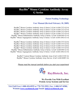
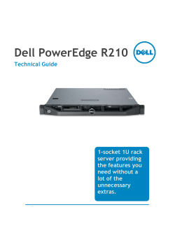
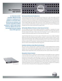

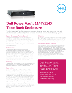
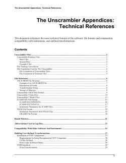
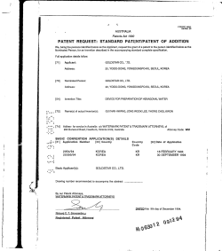
© Copyright 2026