
Installation Operation Maintenance
Installation
Operation
Maintenance
RTHD
Water-cooled
Helical-rotary chillers
500 - 1500 kW
RLC-SVX05E-E4
© Trane 2012
RLC-SVX05E-E4
Contents
General Information
Installation - Mechanical
Installation - Electrical
Operating Principles Mechanical
Unit Start-up
Periodic Maintenance
Maintenance Procedures
RLC-SVX05E-E4
4
11
34
43
51
56
59
3
General information
Foreword
Reception
These instructions are given as a guide
to good practice in the installation,
start-up, operation, and maintenance
by the user, of Trane RTHD chillers.
They do not contain full service
procedures necessary for the
continued successful operation of this
equipment. The services of a qualified
technician should be employed
through the medium of a maintenance
contract with a reputable service
company. Read this manual
thoroughly before unit start-up.
On arrival, inspect the unit before
signing the delivery note.
Units are assembled, pressure tested,
dehydrated, charged and run tested
before shipment.
Warnings and cautions
Warnings and Cautions appear at
appropriate sections throughout this
manual. Your personal safety and the
proper operation of this machine
require that you follow them carefully.
The constructor assumes no liability for
installations or servicing performed by
unqualified personnel.
WARNING: Indicates a potentially
hazardous situation which, if not
avoided, could result in death or
serious injury.
CAUTION: Indicates a potentially
hazardous situation which, if not
avoided, may result in minor or
moderate injury. It may also be used
to alert against unsafe practices or
for equipment or property-damageonly accidents.
Safety recommendations
To avoid death, injury, equipment
or property damage, the following
recommendations should be observed
during maintenance and service visits:
1. The maximum allowable pressures
for system leak testing on low and
high pressure side are given in the
chapter "Installation". Always
provide a pressure regulator.
2. Disconnect the main power supply
before any servicing on the unit.
Reception in France only:
In case of visible damage:
The consignee (or the site
representative) must specify any
damage on the delivery note,
legibly sign and date the delivery
note, and the truck driver must
countersign it. The consignee (or the
site representative) must notify
Trane Epinal Operations - Claims
team and send a copy of the delivery
note. The customer (or the site
representative) should send
a registered letter to the last
carrier within 3 days of delivery.
Note: For deliveries in France, even
concealed damage must be looked
for at delivery and immediately
treated as visible damage.
Reception in all countries except
France:
In case of concealed damage:
The consignee (or the site
representative) must send
a registered letter to the last carrier
within 7 days of delivery, claiming
for the described damage. A copy of
this letter must be sent to Trane
Epinal Operations - Claims team.
Warranty
Warranty is based on the general
terms and conditions of the
manufacturer. The warranty is void
if the equipment is repaired or
modified without the written
approval of the manufacturer, if the
operating limits are exceeded or if the
control system or the electrical wiring
is modified. Damage due to misuse,
lack of maintenance or failure to
comply with the manufacturer's
instructions or recommendations
is not covered by the warranty
obligation. If the user does not
conform to the rules of this manual,
it may entail cancellation of warranty
and liabilities by the manufacturer.
3. Service work on the refrigeration
system and the electrical system
should be carried out only by
qualified and experienced personnel.
4
RLC-SVX05E-E4
General information
Refrigerant
Maintenance contract
Loose Parts Inventory
The refrigerant provided by the
manufacturer meets all the
requirements of our units. When using
recycled or reprocessed refrigerant, it
is advisable to ensure its quality is
equivalent to that of a new refrigerant.
For this, it is necessary to have a
precise analysis made by a specialized
laboratory. If this condition is not
respected, the manufacturer warranty
could be cancelled.
It is strongly recommended that you
sign a maintenance contract with your
local Service Agency. This contract
provides regular maintenance of your
installation by a specialist in our
equipment. Regular maintenance
ensures that any malfunction is
detected and corrected in good time
and minimizes the possibility that
serious damage will occur. Finally,
regular maintenance ensures the
maximum operating life of your
equipment. We would remind you that
failure to respect these installation and
maintenance instructions may result in
immediate cancellation of the
warranty.
Check all items against the shipping
list. Water flow switch (optional),
water vessel drain plugs, isolation
pads, rigging and electrical
diagrams, and service literature are
shipped in the starter control panel.
Environmental Protection /
Compliance with F-Gas
regulation
This equipment contains a fluorinated
gas covered by the Kyoto Protocol
[or an ozone depleting substance
covered by Montreal Protocol].
The type and quantity of refrigerant
per circuit is indicated on the product
nameplate. The Global Warming
Potential of the refrigerant
implemented in Trane Air Conditioning
and Refrigeration Equipment is
presented in the table by type of
refrigerant.
Refrigerant type
GWP (1) value
R134a
1300
The operator (contractor or end user)
must check local environmental
regulations impacting installation,
operation and disposal of the
equipment; in particular need to
recover environmentally harmful
substances (refrigerant, oil, antifreeze
agents, etc.) Do not vent into the
atmosphere any refrigerant. The
handling of refrigerant shall be fulfilled
by a qualified service engineer.
(1) GWP = global warming potential
(2) Covered by Montreal Protocol
With regards to the refrigerant charge
contained in this chiller, the F-gas
regulation requires 2 inspections,
including leak detection, per year
in the EU. Contact your local Trane
Service team.
RLC-SVX05E-E4
Training
To assist you in obtaining the best use
of it and maintaining it in perfect
operating condition over a long period
of time, the manufacturer has at your
disposal a refrigeration and air
conditioning service school. The
principal aim of this is to give operators
and technicians a better knowledge of
the equipment they are using, or that is
under their charge. Emphasis is
particularly given to the importance of
periodic checks on the unit operating
parameters as well as on preventive
maintenance, which reduces the cost
of owning the unit by avoiding serious
and costly breakdown.
Unit Description
The RTHD units are single compressor,
helical-rotary type, water-cooled liquid
chillers designed for installation
indoors. Each unit is a completely
assembled, hermetic package that is
factory-piped, wired, leak-tested,
dehydrated, charged (refrigerant R134a
or nitrogen), and tested for proper
control operation before shipment.
Figure 1 and Figure 2 show a typical
RTHD unit and its components. Water
inlet and outlet openings are covered
before shipment. The oil tank is factory
charged with the proper amount of
refrigeration oil if the unit is factory
charged with refrigerant R134a.
Unit Inspection
When the unit is delivered, verify
that it is the correct unit and that it is
properly equipped.
This chiller was performance tested
before shipment. The water boxes
drain plugs were withdrawn to avoid
stagnation of the water and possible
freeze-up inside the tube bundle. Rustcoloured stains may be present and
are completely normal, but they must
be wiped off at the time of reception.
5
General Information
Figure 1 - Component Location for Typical RTHD Unit
1 = Starter/control panel
2 = Power cable gland plate for
customer wiring
3 = DynaView interface
4 = Suction line
5 = Oil separator
6 = Oil sump
7 = HP relief valve (with refrigerant
isolation valve option only)
6
8 = Condenser water outlet
9 = Condenser water inlet
10 = Evaporator water outlet
11 = Evaporator water inlet
12 = External control wiring cable
gland plate for customer wiring
13 = Gas pump
14 = Liquid level sensor
15 = Evaporator
RLC-SVX05E-E4
General Information
Figure 2 - Component Location for Typical RTHD Unit (Back View)
17 = Compressor
18 = Discharge line
19 = Unit nameplate (on side of
starter/control panel)
20 = EXV
21 = Oil sump (the oil distribution
system is located between the
condenser and the evaporator
22 = Service valves (with refrigerant
isolation valve option only)
23 = Condenser
24 = Pressure gauges
25 = Hot oil filter
26 = 2-stage high pressure cutout
switch
27 = Cold oil filter
RLC-SVX05E-E4
7
General Information
Installation Overview
Table 1 summarizes responsibilities
that are typically associated with the
RTHD chiller installation process.
• Locate and maintain the loose
parts. Loose parts are located in
the control panel.
in the water piping, adjacent to the
inlet and outlet connections of both
the evaporator and the condenser.
• Supply and install drain valves on
each water box.
• Supply and install vent cocks on
each water box.
• Install the unit on a foundation with
flat support surfaces, level within
6 mm and of sufficient strength to
support concentrated loading. Place
the manufacturer-supplied isolation
pad assemblies under the unit.
• Where specified, supply and install
strainers ahead of all pumps and
automatic modulating valves.
• Install the unit per the instructions
outlined in the "Mechanical
Installation" section.
• Start the unit under supervision of
a qualified service technician.
• Complete all water piping and
electrical connections.
Note: Field piping must be arranged
and supported to avoid stress on the
equipment. It is strongly
recommended that the piping
contractor provide at least 1m of
clearance between the preinstallation piping and the planned
location of the unit. This will allow
for proper fit-up upon arrival of the
unit at the installation site. All
necessary piping adjustments can be
made at that time
• Supply and install refrigerant
pressure relief piping from the
pressure relief to the atmosphere.
• Where specified, supply and
insulate the evaporator and any
other portion of the unit, as
required, to prevent sweating under
normal operating conditions.
• For unit-mounted starters, cutouts
are provided at the top of the panel
for line-side wiring.
• Supply and install the wire terminal
lugs to the starter.
• Supply and install field wiring to
the line-side lugs of the starter.
• Where specified, supply and install
valves in the water piping upstream
and downstream of the evaporator
and condenser water boxes, to
isolate the shells for maintenance
and to balance/trim the system.
• Supply and install flow switches or
equivalent devices in both the
chilled water and condenser water
piping. Interlock each switch with
the proper pump starter and
CH.530, to ensure that the unit can
only operate when water flow is
established.
• Supply and install taps for
thermometers and pressure gauges
8
RLC-SVX05E-E4
General Information
Table 1 - Installation Responsibility
Requirement
Trane supplied
Trane installed
Trane supplied
Field installed
Rigging
- Safety chains
- Lifting beam
Isolation
Electrical
Field supplied
Field installed
- Isolation pads
- Circuit breakers
Water piping
- Flow switches(may
be field supplied)
- Circuit breakers or fusible
disconnect
- Customer's starter panel
- BAS wiring
- Control voltage wiring
- Water pump contactor
- Flow switches(may
be field supplied)
-Thermometers
- Water flow pressure gauges
- Isolation and balancing
valves water piping
- Vents and drain valves
- Pressures relief valves for
water side
Pressure relief
- Relief valves
- Vent line
Insulation
- Insulation(optional)
- Insulation
RLC-SVX05E-E4
9
General Information
General Data
Compressor
Evaporator
Condenser
Evaporator water volume total (l)
Condenser water volume total (l)
Oil volume total (1)
(l)
Refrigerant charge R134a
(kg)
Sound power level (5)
(dB(A))
Dimensions (2)
Height
(mm)
Length
(mm)
Width
(mm)
Shipping weight (3)
(kg)
Operating weight (3) (4)
(kg)
B1
B1
B1
168
106
17
182
98
B1
C1
D1
225
125
17
217
98
B2
B1
B1
168
106
17
182
98
1850
3170
1600
3920
4190
1850 1850
3640 3170
1600 1600
4230 3920
4560 4190
B2
C1
D1
225
125
17
217
98
C1 C1 C1 C2 C2 C2
D6 D5 D3 D6 D5 E1
E5 E4 E3 E5 E4 F1
193 220 281 193 220 300
132 148 181 132 148 235
23 23 23 23 23 38
217 217 217 217 217 233
98 98 98 98 98 98
1850 1940
3640 3290
1600 1600
4230 5340
4560 5650
D1
D4
E4
220
148
23
211
97
D1
D3
E3
281
181
23
211
97
1940 1940 1940 1940 1940 1940 1940
3290 3290 3290 3290 3670 3290 3290
1600 1600 1600 1600 1600 1600 1600
5430 5650 5340 5430 6040 5720 5900
5790 6100 5650 5790 6550 6080 6340
D1
G1
G1
563
321
42
311
97
D2
D1
E1
248
167
23
211
97
D2
F1
F2
394
224
38
278
97
2035 1940 1940
3850 3290 3690
1800 1600 1600
7750 5860 6660
8600 6260 7260
D2
G2
G1
597
321
42
311
97
D3
D1
E1
248
167
23
211
97
D3
F1
F2
394
224
38
278
97
2040 1940 1940
3850 3290 3690
1800 1600 1600
7960 5890 6990
8830 6260 7280
D3
G2
G2
597
370
42
311
97
E3
D2
E2
265
178
23
211
101
E3
F2
F3
417
240
38
278
101
E3
G3
G3
656
400
42
319
101
2040 1940 1940
3850 3290 3690
1800 1600 1600
8090 5990 6820
9020 6380 7450
2040
3850
1800
8340
9360
(1) If oil cooler is installed, add 1 liter to the oil charge value given for B family units; add 4 liters for all other units.
(2) Overall dimensions are based on 3-pass evap/2 pass cond and LH/RH water connections, except for DGG/EGG: 4 passes evap /
2 passes cond. Refer to submittals for exact job configurations
(3) All weights ±3%, include standard 10 bar water boxes.
(4) Operating weights include refrigerant, oil, and water charges
(5) At full load and in accordance with ISO 9614
10
RLC-SVX05E-E4
Installation - Mechanical
Storage
Vibration Eliminators
If the chiller is to be stored more
than one month prior to installation,
observe the following precautions:
• Provide rubber boot type isolators
for all water piping at the unit.
• Do not remove the protective
coverings from the electrical panel.
• Store the chiller in a dry, vibrationfree, secure area.
• At least every three months, attach
a gauge and manually check the
pressure in the refrigerant circuit. If
the refrigerant pressure is below 5
bar at 21°C (3 bar at 10 °C), call a
qualified service organization and
the appropriate Trane sales office.
NOTE: Pressure will be
approximately 1.0 bar if shipped with
the optional nitrogen charge.
Noise Considerations
• Refer to Engineering Bulletin for
sound consideration applications.
• Locate the unit away from soundsensitive areas.
• Install the isolation pads under the
unit. Refer to "Unit Isolation."
• Install rubber vibration isolators in
all water piping.
• Use flexible electrical conduit for
final connection to the CH.530.
• Seal all wall penetrations.
NOTE: Consult an acoustical
engineer for critical applications.
Foundation
Provide rigid, non-warping mounting
pads or a concrete foundation of
sufficient strength and mass to
support the chiller operating weight
(including completed piping and full
operating charges of refrigerant, oil
and water).
• Provide flexible conduit for
electrical connections to the unit.
• Isolate all pipe hangers and be sure
they are not supported by main
structure beams that could
introduce vibration into occupied
spaces.
• Make sure that the piping does not
put additional stress on the unit.
NOTE: Do not use metal braided type
eliminators on the water piping.
Metal braided eliminators are not
effective at the frequencies at which
the unit will operate.
Clearances
Provide enough space around the
unit to allow the installation and
maintenance personnel unrestricted
access to all service points. A
minimum of 1 m is recommended
for compressor service and to
provide sufficient clearance for the
opening of control panel doors.
Refer to Figure 3 for minimum
clearances required for condenser or
evaporator tube service. In all cases,
local codes will take precedence over
these recommendations. If the room
configuration requires a variance to
the clearance dimensions, contact
your sales representative.
NOTE: Required vertical clearance
above the unit is 1 m. There should
be no piping or conduit located over
the compressor motor.
NOTE: Maximum clearances are
given. Depending on the unit
configuration, some units may
require less clearance than others in
the same category.
Refer to Table 8 for unit operating
weights.
Once in place, level the chiller within
6 mm over its length and width.
The manufacturer is not responsible
for equipment problems resulting
from an improperly designed or
constructed foundation.
RLC-SVX05E-E4
11
Installation - Mechanical
Figure 3 - Recommended clearances
1 = Service clearance
2 = Tube removal clearance
Ventilation
Access Restrictions
The unit produces heat even though
the compressor is cooled by the
refrigerant. Make provisions to
remove heat generated by unit
operation from the equipment room.
Ventilation must be adequate to
maintain an ambient temperature
lower than 40°C. Vent the pressure
relief valves in accordance with all
local and national codes. Refer to
"Pressure Relief Valves". Make
provisions in the equipment room to
keep the chiller from being exposed
to ambient temperatures below 10°C.
Door clearances for the RTHD units
are given on pages 18-23. Refer to
the unit submittals for specific
dimensional information.
Water Drainage
Locate the unit near a large capacity
drain for water vessel drain-down
during shutdown or repair.
Condensers and evaporators are
provided with drain connections.
Refer to "Water Piping." All local and
national codes apply.
12
Lifting Procedure
WARNING
Heavy Equipment!
Always use lifting equipment with
a capacity exceeding unit lifting
weight by an adequate safety factor
(+10%). Follow the procedures and
diagrams in this manual and in the
submittal. Failure to do so can result
in death personal injury.
CAUTION
Equipment Damage!
Never use a forklift to move the unit.
The skid is not designed to support
the unit at any one point and using a
forklift to move the equipment may
cause unit damage. Always position
the lifting beam so that cables do
not contact the unit. Failure to do so
may result in unit damage.
RLC-SVX05E-E4
Installation - Mechanical
NOTE: If absolutely necessary, the
chiller can be pushed or pulled
across a smooth surface if it is bolted
to wood shipping mounts.
WARNING:
Shipping Mounts!
Do not use the threaded holes in the
compressor to lift or assist in lifting
the unit. They are not intended for
that purpose. Do not remove the
wood mounts (option) until the unit
is in its final location. Removal of
wood shipping mounts prior to unit
final locating could result in death or
serious injury or equipment damage.
1. When the unit is at its final
location, remove the shipping
bolts that secure the unit to the
wood base mounts (option).
2. Rig the unit properly and lift from
above or jack the unit (alternate
moving method). Use the points
shown on the rigging diagram that
ships with the unit as shown in
Figure 4. Remove the base
mounts.
3. Install clevis connectors in lifting
holes provided on the unit. Attach
lifting chains or cables to clevis
connectors as shown in Figure 4.
Each cable alone must be strong
enough to lift the chiller.
panel enclosure.
5. Connect an anti-rotation strap or
cable loosely between the lifting
beam and the threaded coupling
or eyelet provided at the top of the
compressor. Use an eyebolt or
clevis to secure the strap at the
coupling or eyelet.
NOTE: The anti-rotation strap is not a
lifting chain, but a safety device to
ensure that the unit cannot tilt during
lifting.
Alternate Moving Method
If it is not possible to rig from above
as shown in the figures, the unit may
also be moved by jacking each end
high enough to move an equipment
dolly under each tube sheet support.
Once securely mounted on the
dollies, the unit may be rolled into
position.
WARNING: Connect an anti-rotation
strap between the lifting beam and
compressor before lifting unit.
Failure to do so may result in death
or serious injury should a lifting
cable fail.
4. Attach cables to lifting beam. Total
lifting weight, lifting weight
distribution and required lifting
beam dimensions are shown in
the rigging diagram shipped with
each unit and in Figure 4. The
lifting beam crossbar must be
positioned so the lifting cables do
not contact unit piping or electrical
RLC-SVX05E-E4
13
Installation - Mechanical
Figure 4
1 = Anti-rotation cable
2 = ø 55 mm lifting holes
3 = Unit model number location
4 = M16 internal thread
Table 2 - Weights and Rigging
Unit
Configuration*
B1 B1 B1
Lifting Weight
(kg)
3920
Dimension
(mm)
CENTER OF GRAVITY
(mm)
A
B
C
(D)
E(2x)
F(2x)
X
Y
Z
2100
103
1153
600
1900
1650
581
1476
902
B1 C1 D1
4225
2100
99
925
600
1950
1700
568
1480
853
B2 B1 B1
3920
2100
103
1153
600
1900
1650
581
1476
902
B2 C1 D1
4225
2100
99
925
600
1950
1700
568
1480
853
C1 D6 E5
5340
2100
226
1198
600
1900
1650
662
1521
1022
C1 D5 E4
5430
2100
226
1198
600
1900
1650
662
1521
1022
C1 D3 E3
5650
2100
226
1198
600
1900
1650
662
1521
1022
C2 D6 E5
5340
2100
226
1198
600
1900
1650
662
1521
1022
C2 D5 E4
5430
2100
226
1198
600
1900
1650
662
1521
1022
C2 E1 F1
6040
3500
136
1760
600
1950
1750
670
1612
1040
D1 D4 E4
5720
2100
226
1198
600
1900
1650
662
1521
1022
D1 D3 E3
5895
2100
226
1198
600
1900
1650
662
1521
1022
D2 D1 E1
5855
2100
226
1198
600
1900
1650
662
1521
1022
D3 D1 E1
5885
2100
226
1198
600
1900
1650
662
1521
1022
D2 F1 F2
6655
3500
49
1760
600
1950
1750
703
1611
970
D3 F1 F2
6685
3500
49
1760
600
1950
1750
703
1611
970
D1 G1 G1
7750
3500
38
1760
600
1950
1650
783
1615
954
D2 G2 G1
7955
3500
38
1760
600
1950
1650
783
1615
954
D3 G2 G2
8085
3500
38
1760
600
1950
1650
783
1615
954
E3 D2 E2
5985
2100
226
1198
600
1900
1650
662
1521
1022
E3 F2 F3
6820
3500
49
1760
600
1950
1750
703
1611
970
E3 G3 G3
8340
3500
38
1760
600
1950
1650
783
1615
954
*Designator corresponds to digits 6, 7, 14, 15, 21, 22 of model number
14
RLC-SVX05E-E4
Installation - Mechanical
Isolation Pads
The elastomeric pads shipped (as
standard) are adequate for most
installations. For additional details
on isolation practices, consult an
acoustical engineer for sensitive
installations.
8. The unit is shipped with 5 spacers
(only 3 on B family) on the
compressor mount that protect the
compressor isolation pads during
shipping and in handling. Remove
these spacers (Figure 6, 7) before
the unit is operated.
7. During final positioning of the
unit, place the isolation pads
under the evaporator and
condenser tube sheet supports as
shown in Figure 5. Level the unit.
9. Remove the shipping brackets
from the bottom sides of the oil
separator(s) (Figure 7).
Figure 5
8mm
NOTE: Once shipping bracket(s) is
removed, the oil separator is only
supported by the discharge line.
RLC-SVX05E-E4
Figure 6
Figure 7
1= Spacer to be removed
1 = Shipping bracket to be removed
15
Installation - Mechanical
Unit Leveling
NOTE: The electrical panel side of
the unit is designated as the "front"
of the unit.
1. Check unit level end-to-end by
placing a level on the top surface
of the evaporator shell.
2. If there is insufficient surface
available on the top of the
evaporator shell, attach a
magnetic level to the bottom of
the shell to level the unit. The unit
should be level to within 6 mm
over its length.
3. Place the level on the evaporator
shell tube sheet support to check
side-to-side (front-to-back) level.
Adjust to within 6 mm of level
front-to-back. NOTE: The
evaporator MUST be level for
optimum heat transfer and unit
performance.
4. Use full-length shims to level the
unit.
16
RLC-SVX05E-E4
Installation - Mechanical
Water Piping
Piping Connections
To prevent equipment damage,
bypass the unit if using an acidic
flushing agent.
Make water piping connections to
the evaporator and condenser.
Isolate and support piping to prevent
stress on the unit. Construct piping
according to local and national
codes. Insulate and flush piping
before connecting to unit.
Use grooved pipe connectors for all
water piping connections (refer to
Figure 8). Evaporator and condenser
water inlet and outlet sizes and
locations are shown by the unit
submittals . The designation in the
tables corresponds to the
compressor frame code followed by
the evaporator shell code followed
by the condenser shell code.
Reversing Water Boxes
All water boxes may be reversed
end-for-end. Do not rotate water
boxes. Remove the sensors from the
wells before removing the water
box. Complete the water box switch
procedure and replace the sensors. If
the water boxes are reversed, be
sure to properly rewire the sensors
to the CH.530 bus.
Note: Be certain to replace water
boxes right-side-up to maintain
proper baffle orientation. Use new orings
Figure 8 - Dimension of tube stub for grooved connection
ØD
6" (168.3)
8" (219.1)
RLC-SVX05E-E4
A ± 0.8
15.87
19.05
B± 0.8
9.52
11.11
C + 0 -0.7
164
214.4
E MINI
5.56
6.04
F
2.15
2.34
17
Installation - Mechanical
RTHD B1 B1 B1 / B2 B1 B1
Note: Connection configuration is available left or right hand.
1 = Evaporator
2 = Condenser
Left hand
Right hand
Evaporator 2 passes (option)
Right hand
Evaporator 3 passes (standard)
Right hand
Evaporator 4 passes (option)
Right hand
Condenser 2 passes (standard)
Right hand
18
WATER BOX TYPE
A
B
C
D
E
F
G
H
J
K
10 bar
168
213
726
352
163
123
203
203
334
588
21 bar
183
418
711
367
183
148
283
358
348
575
RLC-SVX05E-E4
Installation - Mechanical
RTHD B1 C1 D1 / B2 C1 D1
Note: Connection configuration is available left or right hand.
1 = Evaporator
2 = Condenser
Left hand
Right hand
Evaporator 2 passes (option)
Right hand
Evaporator 3 passes (standard)
Right hand
Evaporator 4 passes (option)
Right hand
Condenser 2 passes (sandard)
Right hand
RLC-SVX05E-E4
WATER BOX TYPE
A
B
C
D
E
F
G
H
J
K
10 bar
168
213
726
352
163
123
203
203
334
588
21 bar
183
418
711
367
183
148
283
358
348
575
19
Installation - Mechanical
RTHD
C1 D6 E5 / C1 D5 E4
C1 D3 E3 / C2 D6 E5
C2 D5 E4 / D1 D4 E4
D1 D3 E3 / D2 D1 E1
D3 D1 E1 / E3 D2 E2
Note: Connection configuration is available left or right hand.
1 = Evaporator
2 = Condenser
Right hand
Left hand
Evaporator 2 passes (option)
Right hand
Evaporator 4 passes (option)
Right hand
Evaporator 3 passes (standard)
Right hand
Condenser 2 passes (standard)
Right hand
A
B
C
D
E
F
G
H
J
K
10 bar
173
201
230
766
378
173
181
150
199
199
359
657
21 bar
183
418
750
395
183
178
323
398
373
643
WATER BOX TYPE
20
RLC-SVX05E-E4
Installation - Mechanical
RTHD C2 E1 F1
Note: Connection configuration is available left or right hand.
1 = Evaporator
2 = Condenser
Right hand
Left hand
Evaporator 2 passes (option)
Right hand
Evaporator 4 passes (option)
Right hand
Evaporator 3 passes (standard)
Right hand
Condenser 2 passes (standard)
Right hand
A
B
C
D
E
F
G
H
J
K
10 bar
173
201
230
766
378
173
181
150
199
199
359
657
21 bar
183
418
750
395
183
178
323
398
373
643
WATER BOX TYPE
RLC-SVX05E-E4
21
Installation - Mechanical
RTHD
D2 F1 F2
D3 F1 F2
E3 F2 F3
Note: Connection configuration is available left or right hand.
1 = Evaporator
2 = Condenser
Right hand
Left hand
Evaporator 3 passes (standard)
Right hand
Evaporator 2 passes (option)
Right hand
Evaporator 4 passes (option)
Right hand
Condenser 2 passes (standard)
Right hand
A
B
C
D
E
F
G
H
J
K
10 bar
173
218
230
238
766
720
378
288
173
189
150
199
199
359
657
21 bar
183
228
418
458
750
708
395
299
183
228
178
323
398
373
643
WATER BOX TYPE
22
RLC-SVX05E-E4
Installation - Mechanical
RTHD
D1 G1 G1 / D2 G2 G1
D3 G2 G2 / E3 G3 G3
Note: Connection configuration is available left or right hand.
1 = Evaporator
2 = Condenser
Right hand
Left hand
Evaporator 4 passes (standard)
Right hand
Evaporator 3 passes (option)
Right hand
Evaporator 6 passes (option)
Right hand
Condenser 2 passes (standard)
Right hand
A
B
C
D
E
F
G
H
J
K
10 bar
173
238
230
276
766
860
378
289
173
235
150
184
199
232
199
378
359
734
657
21 bar
183
248
418
458
750
854
395
295
183
248
178
188
323
398
375
373
736
643
WATER BOX TYPE
RLC-SVX05E-E4
23
24
B1
C1
D1
B2
B1
B1
B2
C1
D1
C1
D6
E5
C1
D5
E4
C1
D3
E3
C2
D6
E5
C2
D5
E4
C2
E1
F1
D1
D4
E4
D1
D3
E3
D1
G1
G1
D2
D1
E1
D2
F1
F2
D2
G2
G1
D3
D1
E1
D3
F1
F2
D3
G2
G2
E3
D2
E2
E3
F2
F3
E3
G3
G3
584
584
584
673
673
673
673
673
673
673
673
851
673
737
851
673
737
851
673
737
851
200
150
100
/
200
150
100
/
200
150
100
/
200
200
150
/
200
200
150
/
200
200
150
/
200
200
150
/
200
200
150
/
200
200
150
/
200
200
150
/
200
200
150
/
/
250
200
150
200
200
150
/
250
200
150
/
/
250
200
150
200
200
150
/
250
200
150
/
/
250
200
150
200
200
150
/
250
200
150
/
/
250
200
150
476
476
476
558
558
558
558
558
558
558
558
654
558
558
654
558
558
654
558
558
654
150
150
150
200
200
200
200
200
200
200
200
200
200
200
200
200
200
200
200
200
200
Installation - Mechanical
Table 3 - Evaporator and Condenser Data
Compressor
B1
Evaporator
B1
Condenser
B1
Evaporator
Shell diameter
(mm)
584
Nominal Conn. Size
2 passes
(mm)
200
3 passes
(mm)
150
4 passes
(mm)
100
6 passes
(mm)
/
Condenser
Shell diameter
(mm)
476
Nominal Conn. Size
2 passes
(mm)
150
RLC-SVX05E-E4
RLC-SVX05E-E4
Table 4 - Evaporator water pressure drop (kPa)
Water flow rates (l/s) for water only
15
15
37
20
8
26
62
28
20
48
25
22
18
21
15
36
21
15
36
12
28
20
48
24
25 30 35 40
13 18 23 30
39 55 72 91
92 129
9 13 18 23
30 41 55 69
71 99 131 168
12 15
16 23 31 39
38 53 70 89
10 13
14 20 26 34
33 46 61 78
10
12 17 22 29
28 39 51 65
10 13 17
23 32 42 53
55 76 101 129
10 13 17
23 32 42 54
55 77 102 130
10 13 18 23
30 42 55 70
72 100 133 170
10 13
16 22 29 37
36 50 66 84
25
28
15
35
65 70 75
71
80 85
28 34 40 47
86 104 123
54 62 70
78 88
19
48
111
16
42
96
13
36
81
21
66
161
21
66
161
28
87
23
58
134
20
51
117
16
43
98
25
80
32
81
28
71
164
22
60
136
35
112
16
46
104
10
20 26 32
46 59 73
52
42
23 29
56 71 89
31
43
19
60
30
60
62
23 28 34
41 53 65
14 18
25 33 41
79 101 125
15
22 28 35
69 88 109
22
37
45 50 55
37 44 53
113
27
69
160
24
60
139
19
51
116
30
95
90 95 100
105 110 115 120 125 130 135 140 145 150 155 160
37 42 48 54 60
94 108 122
67 74 81
89 97
33 38 43 48 54
82 94 106 119
60 66 72
79 87
94 102
26 30 34 38 42 47 52 57
69 79 89 100 112
158
41 47 53 60 66 74 81
62 68
73 79 85
58 64 71
77 84
91 99
30 34 37 41 45
90 101 112 123136
49 54
58 63 67
72
78
83
88
94 100
27
90
186
51
115
30 33 37 40
100 110 121132
44 48
144
52 56 60
65
69
74
79
84 89 95
57 63 70 76
128 142 156171
83 91
187
98 106 114 123 131 140
26 30 35 41 47 53
80 95 112
60 67
34 40
105
47
55 62 71
80
20
56
126
13
39
89
11
41
79
22
49
151
19
43
132
15
35
107
28
77
175
18
54
123
16
55
110
30
68
210
26
60
183
21
48
149
32 37 42 47 53
89 102 115 130
24
66
149
15
46
105
13
48
94
26
58
179
23
51
156
18
41
127
21
62
143
18
63
127
35
79
243
31
69
212
25
56
172
24
71
163
21
72
146
40
90
278
35
79
242
28
64
197
27
80
185
24
81
166
46
102
40
89
275
32
73
223
92
74 82
45 50 55 61 67
100 112 124 136150
73 79 86 93 100 107 115 122 130 139
163 178
36 41 45 50 54
82 91 101 111122
251 280
59 65 70 76 81 87
133 145 157 170 183
93 100 106 113 120 127
Installation - Mechanical
Evap Passes Min Max 10
B1
2
19
69
B1
3
13
46
B1
4
10
34 17
C1
2
25
88
C1
3
17
59
C1
4
13
44
D1
2
32 114
D1
3
21
76
D1
4
16
57
D2
2
35 124
D2
3
23
83
D2
4
18
62
D3
2
37 134
D3
3
25
89
D3
4
19
67
D4
2
27
97
D4
3
18
64
D4
4
14
48
D5
2
27
97
D5
3
18
64
D5
4
14
48
D6
2
23
81
D6
3
15
54
D6
4
12
40
E1
2
35 124
E1
3
23
83
E1
4
18
62
F1
2
43 156
F1
3
29 104
F1
4
22
78
F2
2
46 168
F2
3
31 112
F2
4
23
84
G1
3
39 140
G1
4
29 105
G1
6
20
70
G2
3
42 152
G2
4
32 114
G2
6
21
76
G3
3
47 172
G3
4
36 129
G3
6
24
86
25
26
Water flow rates (l/s) for water only
Cond Passes Min Max 10
B1
2
15
53
D1
2
15
53
E1
2
22
80
E2
2
24
87
E3
2
25
89
E4
2
19
67
E5
2
16
57
F1
2
29 104
F2
2
27
97
F3
2
30 106
G1
2
34 123
G2
2
41 148
G3
2
45 163
15
10
11
20
16
19
11
15
25
24
28
12
10
10
17
22
30
34
39
17
15
13
23
31
12
14
12
35
44
52
22
19
18
31
40
16
18
16
13
40
56
66
28
24
22
39
51
20
23
20
17
45
70
81
34
30
28
48
63
25
29
25
21
16
13
50
85
98
41
36
33
58
77
30
35
31
25
19
16
55
60
65 70 75
80 85
49
43
40
69
91
36
41
36
30
22
19
57
50
46
81
66 76 86
58 66 75
53 61 69
94
97
84 94
78 87
42
48
42
35
26
23
49
56
49
40
30
26
70
81
71
58
44
38
55
64
56
46
34
30
63
72
63
52
39
34
90 95 100
105 110 115 120 125 130 135 140 145 150 155 160
79 87 96 106
90 100 111
79 88 97 106
65 72 79 87
49 54 59 65
42 47 51 56
116
95 103 112 121
71 77 84 90 97 105 112 120 128
62 67 73 78 85 91 97 104 111 118 125 133
Installation - Mechanical
Table 5 - Condenser water pressure drop (kPa)
RLC-SVX05E-E4
Installation - Mechanical
Vents and Drains
Install pipe plugs in evaporator and
condenser water box drain and vent
connections before filling the water
systems. To drain water, remove
vent and drain plugs, install a NPT
connector in the drain connection
and connect a hose to it.
Evaporator Piping
Components
Note: Make sure all piping
components are between the shutoff
valves, so that isolation can be
accomplished on both the condenser
and the evaporator. "Piping
components" include all devices and
controls used to provide proper
water system operation and unit
operating safety. These components
and their general locations are given
below.
To prevent tube damage, install a
strainer in the evaporator water inlet
piping.
Condenser Piping
Components
"Piping components" include all
devices and controls used to provide
proper water system operation and
unit operating safety. These
components and their general
locations are given below.
Entering Condenser Water Piping
• Air vents (to bleed air from system)
• Water pressure gauges with shutoff
valves
• Pipe unions
• Vibration eliminators (rubber boots)
• Shutoff (isolation) valves
• One per each pass
• Thermometers
Entering Chilled Water Piping
• Air vents (to bleed air from system)
• Water pressure gauges with shutoff
valves
• Pipe unions
• Vibration eliminators (rubber boots)
• Shutoff (isolation) valves
• Thermometers
• Clean out tees
• Pipe strainer
Leaving Chilled Water Piping
• Air vents (to bleed air from system)
• Pipe strainer
• Flow switch
Leaving Condenser Water Piping
• Air vents (to bleed air from system)
• Water pressure gauges with shutoff
valves
• Pipe unions
• Vibration eliminators (rubber boots)
• Shutoff (isolation) valve
• One per each pass
• Thermometers
• Water pressure gauges with shutoff
valves
• Clean out tees
• Pipe unions
• Pressure relief valve
• Vibration eliminators (rubber boots)
To prevent condenser damage, do
not exceed 10 bar water pressure for
standard water boxes.
Maximum pressure for high pressure
water boxes is 21 bar. Refer to the
order write-up.
To prevent tube damage, install
a strainer in condenser water inlet
piping.
• Shutoff (isolation) valves
• Thermometers
• Clean out tees
• Balancing valve
• Pressure relief valve
To prevent evaporator damage, do
not exceed 10 bar evaporator water
pressure for standard water boxes.
Maximum pressure for high pressure
water boxes is 21 bar. Refer to order
write-up.
RLC-SVX05E-E4
• Clean out tees
• Balancing valve
27
Installation - Mechanical
Condenser Water
Temperatures
With the model RTHD chiller, a
condenser water control method is
necessary only if the unit starts with
entering water temperatures below
13°C, or between 7°C and 13°C,
when a temperature increase of
0.6°C per minute to 13°C is not
possible.
When the application requires
startup temperatures below the
prescribed minimums, a variety of
options are available. To control a 2way or 3-way valve, Trane offers a
Condenser Regulating Valve Control
option for the CH530 controls.
Condenser leaving water
temperature must be 9°C higher that
evaporator leaving water
temperature within 2 minutes after
start-up. A minimum of 14°C
differential must be maintained
afterwards.
Trane Series R chillers start and
operate successfully and reliably
over a range of load conditions with
controlled entering condenser water
temperature. Reducing the
condenser water temperature is an
effective method of lowering chiller
power input required, but the ideal
temperature for optimizing total
system power consumption will
depend on the overall system
dynamics. From a system
perspective, some improvements in
chiller efficiency may be offset by the
increased cooling device fan and
pumping costs required to achieve
the lower cooling device
temperatures.
28
Contact your local Trane systems
solution provider for more
information on optimizing system
performance.
The minimum acceptable refrigerant
pressure differential between
condenser and evaporator is 1.7 Bar.
The chiller control system will
attempt to obtain and maintain this
differential at startup, but for
continuous operation a design
should maintain a 14°C differential
from evaporator leaving water
temperature to condenser leaving
water temperature.
CAUTION! In case of low evaporator
leaving water temperature
applications, the non use of glycol
on the condenser side may result in
condenser tube freeze-up.
Condenser Water
Regulation
The Condenser Head Pressure
Control Option provides for a 010VDC (maximum range -a smaller
range is adjustable) output interface
to the customer's condenser water
flow device. This option enables the
CH530 controls to send a signal for
opening and closing a 2-way or 3way valve as necessary to maintain
chiller differential pressure.
Methods other than those shown can
be employed to achieve the same
results. Contact your local Trane
office for details.
Contact the manufacturer of the
cooling device for compatibilty with
variable water flow.
Throttling valve (Figure 9)
This method maintains condensing
pressure and temperature by
throttling water flow leaving the
condenser in response to condenser
pressure or system differential
pressures.
Advantages:
• Good control with proper valve
sizing at relatively low cost.
• Pumping cost can be reduced.
Disadvantages:
• Increased rate of fouling due to
lower condenser water velocity.
• Requires pumps that can
accommodate variable flow.
RLC-SVX05E-E4
Installation - Mechanical
Condenser water pump with
variable frequency drive (Figure 11)
Advantages:
Figure 9
• Pumping cost can be reduced.
Good cooling device temperature
control.
3
1
4
2B
• Relatively low first cost.
Disadvantage:
CDS
7
4
5A
• Increased rate of fouling due to
lower water velocity in the
condenser.
Figure 11
6
EVP
Cooling device bypass (Figure 10)
Cooling device bypass is also a valid
control method if the chiller
temperature requirements can be
maintained.
CDS
7
5B
4
8
Advantage:
• Excellent control by maintaining
constant water flow through the
condenser.
EVP
Disadvantage:
• Higher cost because of the
dedicated pump required for each
chiller if condenser pressure is the
control signal.
Figure 10
3
1
4
2A
1 = Electric valve actuator
2A = 3-way valve or 2 butterfly
valves
2B = 2 butterfly valves
3 = RTHD controller
4 = Refrigerant pressure line
5A = Condenser water pump
5B = Condenser water pump with
VFD
6 = To/from cooling load
7 = To/from cooling device
8 = Electric controller
CDS
7
4
5A
6
RLC-SVX05E-E4
EVP
29
Installation - Mechanical
Condenser Water
Regulating Valve
Adjustment
A separate TechView Settings Menu
tab entitled "Condenser Head
Pressure Control -Setup" that is only
visible if the configuration is
selected, contain the following
settings and manual overrides for
user adjustments and
commissioning all under one tab:
• "Off State" Output Command
(0-10 Vdc, 0.1 volt increments,
Default 2.0 Vdc)
• Output Voltage @Desired Minimum
Flow (Adj:0 to 10.0 in 0.1 volt
increments, Default 2.0 Vdc)
• Desired Minimum Flow (Adj:0-100%
of full flow in 1%intervals, Default
20%)
• Output Voltage @Desired
Maximum Flow (Adj:0 to 10.0 in 0.1
volt increments (or finer),Default 10
Vdc)
• Actuator Stroke Time (Min to Max
Range Time)(Adj:1 to 1000 seconds,
in 1 second increments, Default
30s)
• Damping Coefficient (adj:0.1 to 1.8,
in 0.1 increments, Default .5)
• Head Pressure Control Override
(enumeration of: disabled
(auto),"off" state, minimum,
maximum (100%),) default :
disabled (auto). When this setting is
in "disabled (auto)"
• Condenser Water Pump Prerun
Time
WARNING: In low temperature
chilled water applications, in the
case of a power loss, there is a risk
of a condenser freeze-up. For low
temperature chilled water
applications, it is recommended to
take freeze protection measures.
The following disclamatory label is
provided on each RTHD unit:
The use of improperly treated or
untreated water in this equipment
may result in scaling, erosion,
corrosion, algae or slime. The
services of a qualified water
treatment specialist should be
engaged to determine what
treatment, if any, is advisable.
The warranty specifically excludes
liability for corrosion, erosion or
deterioration of the manufacturer's
equipment. The manufacturer
assumes no responsibilities for the
results of the use of untreated or
improperly treated water, or saline
or brackish water.
Water Pressure Gauges and
Thermometers
Install field-supplied thermometers
and pressure gauges (with
manifolds, whenever practical) as
shown in Figure 12. Locate pressure
gauges or taps in a straight run of
pipe; avoid placement near elbows,
etc. Be sure to install the gauges at
the same elevation on each shell if
the shells have opposite-end water
connections. To read manifolded
water pressure gauges, open one
valve and close the other (depending
upon the reading desired). This
eliminates errors resulting from
differently calibrated gauges
installed at unmatched elevations.
Refer to Trane Engineering Bulletin Series R. Chiller Sound Ratings and
Installation Guide for soundsensitive applications.
Water Treatment
WARNING: Do not use untreated or
improperly treated water. Use of
untreated or improperly treated
water may result in equipment
damage.
30
RLC-SVX05E-E4
Installation - Mechanical
Figure 12
1 = Evaporator water flow
2 = Isolation valves
3 = Shut off valves
4 = Manifold
5 = Flow switch
6 = Condenser water flow
7 = Pressure differential gauge
8 = Thermometers
9 = Relief valve
RLC-SVX05E-E4
31
Installation - Mechanical
Water Pressure Relief
Valves
Install a pressure relief valve in both
evaporator and condenser water
systems. Failure to do so could
result in shell damage.
Install a water pressure relief valve in
one of the condenser and one of the
evaporator water box drain
connections or on the shell side of
any shutoff valve. Water vessels with
close-coupled shutoff valves have a
high potential for hydrostatic
pressure buildup on a water
temperature increase. Refer to
applicable regulation for relief valve
installation guidelines.
Flow Sensing Devices
Use field-provided flow switches or
differential pressure switches with
pump interlocks to sense system
water flow. Flow switch locations are
schematically shown in Figure 12.
To provide chiller protection, install
and wire flow switches in series with
the water pump interlocks, for both
chilled water and condenser water
circuits (refer to the "Installation
Electrical" section). Specific
connections and schematic wiring
diagrams are shipped with the unit.
Flow switches must stop or prevent
compressor operation if either
system water flow drops off
drastically. Follow the
manufacturer's recommendations
for selection and installation
procedures. General guidelines for
flow switch installation are outlined
below.
Note: The CH.530 provides a 6second time delay on the flow switch
input before shutting down the unit
on a loss-of-flow diagnostic. Contact
a qualified service organization if
nuisance machine shutdowns
persist. Adjust the switch to open
when water flow falls below
nominal. Refer to the General Data
table for minimum flow
recommendations for specific water
pass arrangements. Flow switch
contacts are closed on proof of water
flow.
Refrigerant Pressure Relief
Valve Venting
To prevent injury due to inhalation
of R134 gas, do not discharge
refrigerant anywhere. If multiple
chillers are installed, each unit must
have separate venting for its relief
valves. Consult local regulations for
any special relief line requirements.
All relief valve venting is the
responsibility of the installing
contractor. All RTHD units use
condenser pressure relief valves that
must be vented to the outside of the
building. Relief valve connection
sizes and locations are shown in the
unit submittals. Refer to national
regulations for relief valve vent line
sizing information.
• Mount the switch upright, with a
minimum of 5 pipe diameters of
straight, horizontal run on each
side.
• Do not install close to elbows,
orifices or valves.
Note: The arrow on the switch must
point in the direction of the water
flow. To prevent switch fluttering,
remove all air from the water
system.
32
RLC-SVX05E-E4
Installation - Mechanical
Do not exceed vent piping code
specifications. Failure to heed
specifications could result in
capacity reduction, unit damage
and/or relief valve damage.
Note: Once opened, relief valves
tend to leak.
Thermal Insulation
All RTHD units are available with
optional factory-installed thermal
insulation. If the unit is not factoryinsulated, install insulation over the
areas designated in Figure 13.
Note: Filter, refrigerant charging
valves, water temperature sensors,
drain and vent connections when
insulated must remain accessible for
service. Use only water-base latex
paint on factory-applied insulation.
Failure to do so may result in
insulation shrinkage.
Note: Units in environments with
higher humidity or very low leaving
water temperature may require
thicker insulation.
Figure 13
Location
Evaporator
Compressor
All components and piping
on low side of system
(gas pump, return oil line,
filter from pump)
RLC-SVX05E-E4
Type
19 mm
19 mm
Square meters
10
8
19 mm
4
33
Installation - Electrical
General Recommendations
For proper electrical component
operation, do not locate the unit in
areas exposed to dust, dirt, corrosive
fumes, or excessive humidity. If any
of these conditions exist, corrective
action must be taken.
Disconnect all electrical power,
including remote disconnects before
servicing. Failure to disconnect
power before servicing can cause
severe personal injury or death.
All wiring must comply with national
electric regulations. Minimum circuit
ampacities and other unit electrical
data is on the unit nameplate. See
the unit order specifications for
actual electrical data. Specific
electrical schematics and connection
diagrams are shipped with the unit.
Use copper conductors only! Unit
terminals are not designed to accept
other types of conductors. Failure to
do so may cause damage to the
equipment.
Do not allow conduit to interfere
with other components, structural
members or equipment. All conduit
must be long enough to allow
compressor and starter removal.
Note: To prevent control
malfunctions, do not run low voltage
wiring (<30V) in conduit with
conductors carrying more than
30 volts.
Power Supply Wiring
Model RTHD chillers are designed
according to European standard EN
60204; therefore, all power supply
wiring must be sized and selected
accordingly by the project engineer.
Water Pump Power Supply
Provide power supply wiring with
fused disconnect for both the chilled
water and condenser water pumps.
34
Electrical Panel Power Supply
Power supply wiring instructions for
the starter/control panel are:
Run the line voltage wiring in
conduit to the access opening(s) on
the starter/control panel. See the
product catalog for wire sizing and
selection information and refer to
Table 6 and Figure 14 that show
typical electrical connection sizes
and locations. Always refer to
submittal information for your actual
unit specifications.
Note: Asterisked connections require
the user to provide an external
source of power. The 115V control
power transformer is not sized for
additional load.
Compressor Motor Phase
Sequencing
Always verify that proper rotation of
the RTHD compressor is established
before the machine is started. Proper
motor rotation requires confirmation
of the electrical phase sequence of
the power supply. The motor is
internally connected for clockwise
rotation with the incoming power
supply phased A, B, C (L1, L2, L3).
To confirm the correct phase
sequence (ABC), use a phase meter.
Basically, voltages generated in each
phase of a polyphase alternator or
circuit are called phase voltages. In a
3-phase circuit, 3 sine wave voltages
are generated, differing in phase by
120 electrical degrees. The order in
which the 3 voltages of a 3-phase
system succeed one another is called
phase sequence or phase rotation.
This is determined by the direction
of rotation of the alternator. When
rotation is clockwise, phase
sequence is usually called "ABC."
This direction may be reversed
outside the alternator by
interchanging any two of the line
wires. It is this possible interchange
of wiring that makes a phase
sequence indicator necessary if the
operator is to quickly determine the
phase rotation of the motor.
RLC-SVX05E-E4
Installation - Electrical
Table 6 - Compressor Motor Electrical Data - 50 Hz -
Compressor
Code
B1 - B2
C1 - C2
D1 - D2 - D3
E3
Nominal Voltage
Voltage
Utilization
Range
Max motor (kW)
Max. RLA (A)
Inrush current in star connection (A)
Power factor
Max motor (kW)
Max. RLA (A)
Inrush current in star connection (A)
Power factor
Max motor (kW)
Max. RLA (A)
Inrush current in star connection (A)
Power factor
Max motor (kW)
Max. RLA (A)
Inrush current in star connection (A)
Power factor
380
361-399
400
380-420
415
394-436
139
233
391
0.910
201
349
456
0.875
271
455
711
0.905
288
488
711
0.900
145
233
412
0.900
209
349
480
0.865
280
455
748
0.890
301
488
748
0.890
148
233
428
0.880
213
349
498
0.850
284
455
776
0.870
306
488
776
0.870
Table 7 - Electrical Connections
Compressor Code
Option non-fused disconnect switch
Disconnect switch size
Disconnect switch minimum cable cross section
Disconnect switch maximum cable cross section
Option fused disconnect switch
Disconnect switch size
Fuse size
Disconnect switch/fuses minimum
cable cross section
Disconnect switch/fuses maximum
cable cross section
Option Circuit breaker
Circuit breaker size
Circuit breaker minimum cable cross section
Circuit breaker maximum cable cross section
Option Terminal block
Terminal block maximum cable cross section
B1 - B2
C1 - C2
D1 - D2 - D3 - E3
(A)
(mm²)
(mm²)
315
150
240
400
185
240
630
2x150
2x300
(A)
(A)
315
250 T2
500
400 T2
630
500 T3
(mm²)
150
240
2x150
(mm²)
240
240
2x300
(A)
(mm²)
(mm²)
400
2x70
2x240
630
2x70
2x240
630
2x70
2x240
(mm²)
2x300
2x300
2x300
Note: Minimum cable cross section is an electrical component supplier data. It’s up to the electrical contractor to correctly size the
power cable according to the maximum current value.
RLC-SVX05E-E4
35
Installation - Electrical
Module and Control Panel
Connectors
All connectors can be unplugged or
the wires can be removed. If an
entire plug is removed, make sure
the plug and the associated jack are
marked for proper location
identification during reinstallation.
Figure 14 - Electrical panel layout
* OPTION
ELECTRICAL PATH
ELECTRICAL
POWER
ENTRY
36
RLC-SVX05E-E4
Installation - Electrical
Interconnecting Wiring
(Field Wiring Required)
Important: Do not turn chiller on or
off using the chilled water pump
interlocks.
When making field connections,
refer to the appropriate field layout,
wiring, schematics and controls
diagrams that ship with the unit.
Whenever a contact closure (binary
output) is referenced, the electrical
rating is:
At 120 VAC
At 240 VAC
7.2 amp resistive
2.88 amp pilot duty
250 W, 7.2 FLA,
43.2 LRA
5.0 amp resistive
2.0 amp pilot duty
250 W, 3.6 FLA,
21.3 LRA
Whenever a dry contact input (binary
input) is referenced, the electrical
rating is 24VDC, 12 mA.
Whenever a control voltage contact
input (binary input) is referenced, the
electrical rating is 120 VAC, 5mA.
Note: Asterisked connections require
the user to provide an external
source of power. The 115V control
power transformer is not sized for
additional load.
Chilled Water Pump Control
CH.530 has a evaporator water pump
output relay that closes when the
chiller is given a signal to go into the
Auto mode of operation from any
source. The contact is opened to turn
off the pump in the event of most
machine level diagnostics to prevent
the build up of pump heat. To protect
against the build-up of pump heat
for those diagnostics that do not
stop and/or start the pump and to
protect against the condition of a
bad flow switch, the pump shall
always be stopped when refrigerant
pressure is seen to be close to heat
exchanger design pressure.
RLC-SVX05E-E4
Chilled Water Flow Interlock
CH.530 has an input that will accept
a contact closure from a proof-offlow device such as a flow witch. The
flow switch is to be wired in series
with the chilled water pump starter's
auxiliary contacts. When this input
does not prove flow within 20
minutes relative to transition from
Stop to Auto modes of the chiller, or
if the flow is lost while the chiller is
in the Auto mode of operation, the
chiller will be inhibited from running
by a non-latching diagnostic. The
flow switch input shall be filtered to
allow for momentary openings and
closings of the switch due to
turbulent water flow. This is
accomplished with a 6 seconds
filtering time. The sensing voltage
for the condenser water flow switch
is 115/240 VAC
IMPORTANT! DO NOT cycle the
chiller through starting and stopping
the chilled water pump. This could
cause the compressor to shut down
fully loaded. Use the external
stop/start input to cycle the chiller.
37
Installation - Electrical
Condenser Water Pump Control
CH.530 provides a contact closure
output to start and stop the
condenser water pump. If condenser
pumps are arranged in a bank with a
common header, the output can be
used to control an isolation valve
and/or signal another device that an
additional pump is required.
Condenser Water Pump Prestart time
has been added to help with cold
condenser water problems. In very
cold outdoor ambient, the cooling
device’s sump would reach the
chiller some time after the low
system differential pressure
protection had run through its ignore
time, and result in an immediate
shutdown and latching diagnostic.
By simply starting the pump earlier,
and allowing mixing of the warmer
indoor loop with the cooling device’s
sump, this problem can be avoided.
Condenser Water Flow Interlock
The CH.530 shall accept an isolated
contact closure input from a
customer installed proof-of-flow
device such as a flow switch and
customer provided pump starter
auxiliary contact for interlocking with
condenser water flow.
The input shall be filtered to allow
momentary openings and closings of
the switch due to turbulent water
flow, etc. This shall be accomplished
with a 6 seconds filtering time. The
sensing voltage for the condenser
water flow switch is 115/240 VAC.
On a call for cooling after the restart
inhibit timer has timed out, the
CH.530 shall energize the condenser
water pump relay and then check the
condenser water flow switch and
pump starter interlock input for flow
confirmation.
38
Startup of the compressor will not be
allowed until flow has proven. If flow
is not initially established within
1200 seconds (20 minutes) of the
condenser pump relay energizing, an
automatically resetting diagnostic
"Condenser Water Flow Overdue"
shall be generated which terminates
the prestart mode and denergizes
the condenser water pump relay.
This diagnostic is automatically reset
if flow is established at any later
time.
Note: This diagnostic would never
automatically reset if CH.530 was in
control of the condenser pump
through its condenser pump relay
since it is commanded off at the time
of the diagnostic. It could however
reset and allow normal chiller
operation if the pump was controlled
from some external source.
Programmable Relays (Alarm and
Status)-Optional
CH.530 provides a flexible alarm or
chiller status indication to a remote
location through a hard wired
interface to a dry contact closure. 4
relays are available for this function,
and they are provided (generally
with a Quad Relay Output LLID) as
part of the Alarm Relay Output
Option. The events/states that can be
assigned to the programmable
relays are listed in the following
table.
RLC-SVX05E-E4
Installation - Electrical
Table 8 - Chiller events/status descriptions
Event/State
Description
Alarm - Latching
This output is true whenever there is any active diagnostic that requires a
manual reset to clear, that effects the Chiller, the Circuit, or any of the
Compressors on a circuit. This classification does not include informational
diagnostics.
Alarm - Auto Reset
This output is true whenever there is any active diagnostic that could
automatically clear, that effects the Chiller, the Circuit, or any of the
Compressors on a circuit. This classification does not include informational
diagnostics. If all of the auto resetting diagnostics were to clear, this output
would return to a false condition.
Alarm
This output is true whenever there is any diagnostic effecting any component,
whether latching or automatically clearing. This classification does not include
informational diagnostics.
Warning
This output is true whenever there is any informational diagnostic effecting
any component, whether latching or automatically clearing.
Chiller Limit Mode
This output is true whenever the chiller has been running in one of the
Unloading types of limit modes (Condenser, Evaporator, Current Limit or
Phase Imbalance Limit) continuously for the last 20 minutes. A given limit or
overlapping of different limits must be in effect continuously for 20 minutes
prior to the output becoming true. It will become false, if no Unload limits are
present for 1 minute. The filter prevents short duration or transient repetitive
limits from indicating. The chiller is considered to be in a limit mode for the
purposes of front panel display and annunciation, only if it is fully inhibiting
loading by virtue of being in either the "hold" or "forced unload" regions of the
limit control, excluding the"limited loading region". (In previous designs, the
"limit load" region of the limit control was included in the criteria for the limit
mode call out on the front panel and annunciation outputs)
Compressor Running
The output is true whenever any compressors are started or running on the
chiller and false when no compressors are either starting or running on the
chiller. This status may or may not reflect the true status of the compressor in
Service Pumpdown if such a mode exists for a particular chiller.
Chiller Head Pressure Relief
Request Relay
This relay output is energized anytime the chiller is running in one of the
following modes; Ice Making Mode or Condenser Pressure Limit Control Mode
continuously for the duration specified by the Chiller Head Relief Relay Filter
Time. The Chiller Head Relief Relay Filter Time is a service setpoint. The relay
output is de-energized anytime the chiller exits all above modes continuously
for the duration specified by the same Chiller Head Relief Relay Filter Time.
RLC-SVX05E-E4
39
Installation - Electrical
The CH.530 Service Tool (TechView)
is used to install and assign any of
the above listed events or status to
each of the 4 relays provided with
this option. The default assignments
for the 4 available relays are listed
below.
LLID Name
Operating Status
Programmable Relays
LLID Software
Relay Designation
Relay 0
Output Name
Status Relay 4, J2-1,2,3
Default
Head Pressure Relief Request
Relay 1
Relay 2
Status Relay 3, J2-4,5,6
Status Relay 2, J2-7,8,9
Relay 3
Status Relay 1, J2-10,11,12
Chiller Limit Mode Relay
Chiller Alarm Relay
(latching or non-latching)
Compressor Running Relay
Emergency Stop
The CH.530 provides auxiliary
control for a customer
specified/installed latching trip out.
When this customer-furnished
remote contact is provided, the
chiller will run normally when the
contact is closed. When the contact
opens, the unit will trip off on a
manually resettable diagnostic. This
condition requires manual reset at
the chiller switch on the front of the
control panel.
External Auto/Stop
If the unit requires the external
Auto/Stop function, the installer
must provide leads from the remote
contacts to the proper terminals of
the LLID on the control panel. The
chiller will run normally when the
contacts are closed. When the
contact opens, the compressor(s), if
operating, will go to the RUN :
UNLOAD operating mode and cycle
off. Unit operation will be inhibited.
Re-closure of the contacts will permit
the unit to automatically return to
normal operation.
NOTE: A "panic " stop (similar to
"emergency " stop) can be manually
commanded by pressing the STOP
button twice in a row, the chiller will
immediately shut down, but without
creating a latching diagnostic.
40
Soft Loading
Soft loading will prevent the chiller
from going to full capacity during the
pull-down period. The CH.530
control system has two soft loading
algorithms running all of the time.
They are capacity control soft
loading and current limit soft
loading. These algorithms introduce
the use of a Filtered Chilled Water
Setpoint and a Filtered Current Limit
Setpoint. After the compressor has
been started, the starting point of the
filtered chilled water setpoint is
initialized to the value of the Evap
Leaving Water Temperature. The
filtered current limit setpoint is
initialized to the value of the Current
Limit Softload Starting Percent.
These filtered setpoints allow for a
stable pull-down that is user
adjustable in duration. They also
eliminate sudden transients due to
setpoint changes during normal
chiller operation.
3 settings are used to describe the
behavior of soft loading. The setup
for soft loading can be done using
TechView.
• Capacity Control Softload Time:
This setting controls the time
constant of the Filtered Chilled
Water Setpoint. It is settable
between 0 and 120 min.
RLC-SVX05E-E4
Installation - Electrical
• Current Limit Control Softload
Time: This Setting controls the time
constant of the Filtered Current
Limit Setpoint. It is settable
between 0 and 120 minutes.
• Tracer Base Loading Control
Setpoint
• Current Limit Softload Starting %:
This setting controls the starting
point of the Filtered Current Limit
Setpoint. It is adjustable from 20
(40 for RTHD) to 100% RLA.
• External Base Loading Setpoint
External Base Loading - Optional
Primarily for process control
requirements, base loading provides
for immediate start and loading of a
chiller up to an externally or
remotely adjustable current limit
setpoint without regard to
differential to start or stop, or to
leaving water temperature control.
This allows the flexibility to prestart
or preload a chiller in anticipation of
a large load application. It also
allows you to keep a chiller on line
between processes when leaving
water temperature control would
normally cycle the unit.
When the base loading option is
installed through TechView it will be
controllable through DynaView/
TechView, External Hardware
Interface or Tracer (if Tracer is
installed).Order for precedence for
all setpoints, DynaView/TechView
then External then Tracer from
lowest to highest priority. If one of
the higher priority setpoints drops
out due to a bad sensor or
communication loss then base
loading shall go to the next lowest
priority of command and setpoint.
The command settings and control
setpoints associated with base
loading are explained below.
Base Loading Control setpoint
This setpoint has three possible
sources, an External Analog Input,
DynaView/TechView or Tracer.
• DynaView/TechView Base Loading
Control Setpoint
The range is 40 -100 % Compressor
Load (Max %RLA).The default is
50%.
RLC-SVX05E-E4
The range is 40 -100 %Compressor
Load (Max %RLA).The default is
50%.
This is an Analog Input that sets the
base loading setpoint. This signal
can be controlled by either a 2-10Vdc
or 4-20ma Signal based on
configuration information. The
equations show the relationship
between input and percent
compressor load:
If the input is configured as a
4 -20 mA: %Load =3.75 *(mA
Input)+25
If the input is configured as a
2 -10 Vdc: %Load =7.5 *(Vdc
Input)+25
Summit Interface - Optional
CH.530 provides an optional
interface between the chiller and a
Trane Summit BAS.A
Communications interface LLID shall
be used to provide "gateway"
functionality between the chiller and
Summit.
LonTalk Communication Interface Optional
CH.530 provides an optional LonTalk
Communication Interface (LCI-C)
between the chiller and a BAS. An
LCI-C LLID shall be used to provide
"gateway" functionality between the
LonTalk protocol and the chiller.
Ice Making Contact - Optional
CH.530 accepts a contact closure
input to initiate Ice Building. When in
the ice building mode, the
compressor will be fully loaded (not
given a low setpoint) and will
continue to operate until the ice
contacts open or the return water
temperature reaches the Ice
Termination Setpoint. If terminated
on return setpoint, CH.530 will not
allow the chiller to restart until the
ice making contact is opened.
41
Installation - Electrical
Ice Machine Control - Optional
CH.530 provides an output contact
closure that can be used as a signal
to the system that ice building is in
operation. This relay will be closed
when ice building is in progress and
open when ice building has been
terminated by either CH.530 or the
remote interlock. It is used to signal
the system changes required to
convert to and from ice making.
External Chilled Water Setpoint Optional
CH.530 will accept either a 2-10 VDC
or a 4-20 mA input signal, to adjust
the chilled water setpoint from a
remote location.
External Current Limit Setpoint Optional
CH.530 will accept either a 2-10VDC
or a 4-20mA input signal to adjust
the current limit setpoint from a
remote location.
Percent Condenser Pressure Output
-Optional
CH.530 provides a 2-10 VDC analog
output to indicate percent High
Pressure Cutout (HPC) condenser
pressure.
Percent HPC =(Condenser
Pressure/High Pressure Cutout
Setpoint)*100
Compressor Percent RLA Output Optional
CH.530 provides a 0-10 Vdc analog
output to indicate %RLA of
compressor starter average phase
current. 2 to 10 Vdc corresponds to 0
to 120% RLA.
42
RLC-SVX05E-E4
Operating Principles Mechanical
This section contains an overview of
the operation and maintenance of
RTHD chillers equipped with
microcomputer-based control
systems. It describes the overall
operating principles of the RTHD
design. Following the section is
information regarding specific
operating instructions, detailed
descriptions of the unit controls and
options and maintenance procedures
that must be performed regularly to
keep the unit in top condition.
Diagnostic information is provided to
allow the operator to identify system
malfunctions.
Note: To ensure proper diagnosis
and repair, contact a qualified service
organization if a problem should
occur.
General
The Model RTHD units are singlecompressor, helical-rotary type
water-cooled liquid chillers. These
units are equipped with unitmounted starter/control panels. The
basic components of an RTHD unit
are:
• Unit-mounted panel containing
starter and Tracer CH.530 controller
and Input/output LLIDS
• Helical-rotary compressor
• Evaporator
• Electronic expansion valve
• Water-cooled condenser with
integral subcooler
• Oil supply system
• Oil cooler (application dependent)
• Related interconnecting piping
RLC-SVX05E-E4
Refrigeration (Cooling)
Cycle
The refrigeration cycle of the RTHD
chiller is conceptually similar to that
of other Trane chiller products. It
makes use of a shell-and-tube
evaporator design with refrigerant
evaporating on the shell side and
water flowing inside tubes having
enhanced surfaces.
The compressor is a twin-rotor
helical-rotary type. It uses a suction
gas-cooled motor that operates at
lower motor temperatures under
continuous full- and part-load
operating conditions. An oil
management system provides oilfree refrigerant to the shells to
maximize heat transfer performance,
while providing lubrication and rotor
sealing to the compressor. The
lubrication system ensures long
compressor life and contributes to
quiet operation.
Condensing is accomplished in a
shell-and-tube heat exchanger where
refrigerant is condensed on the shell
side and water flows internally in the
tubes.
Refrigerant is metered through the
flow system using an electronic
expansion valve that maximizes
chiller efficiency at part load.
A unit-mounted starter and control
panel is provided on every chiller.
Microprocessor-based unit control
modules (Tracer CH.530) provide for
accurate chilled water control as well
as monitoring, protection and
adaptive limit functions. The
"adaptive" nature of the controls
intelligently prevents the chiller from
operating outside of its limits, or
compensates for unusual operating
conditions, while keeping the chiller
running rather than simply tripping
due to a safety concern. When
problems do occur, diagnostic
messages assist the operator in
troubleshooting.
43
Operating Principles Mechanical
Cycle Description
The refrigeration cycle for the RTHD
chiller can be described using the
pressure-enthalpy diagram shown in
Figure 15. Key State Points are
indicated on the figure and are
referenced in the discussion
following. A schematic of the system
showing the refrigerant flow loop as
well as the lubricant flow loop is
shown in Figure 16.
Evaporation of refrigerant occurs in
the evaporator that maximizes the
heat transfer performance of the
heat exchanger while minimizing the
amount of refrigerant charge
required. A metered amount of
refrigerant liquid enters a
distribution system in the evaporator
shell and is then distributed to the
tubes in the evaporator tube bundle.
The refrigerant vaporizes as it cools
the water flowing through the
evaporator tubes. Refrigerant vapor
leaves the evaporator as saturated
vapor (State Point 1).
The refrigerant vapor generated in
the evaporator flows to the suction
end of the compressor where it
enters the motor compartment of the
suction-gas-cooled motor. The
refrigerant flows across the motor,
providing the necessary cooling,
then enters the compression
chamber. Refrigerant is compressed
in the compressor to discharge
pressure conditions. Simultaneously,
lubricant is injected into the
compressor for two purposes: (1) to
lubricate the rolling element
bearings, and (2) to seal the very
small clearances between the
compressor's twin rotors.
Immediately following the
compression process the lubricant
and refrigerant are effectively
divided using an oil separator. The
oil-free refrigerant vapor enters the
condenser at State Point 2. The
lubrication and oil management
issues are discussed in more detail
in the compressor description and oil
management sections that follow.
44
Baffles within the condenser shell
distribute the compressed refrigerant
vapor evenly across the condenser
tube bundle. Cooling device water,
circulating through the condenser
tubes, absorbs heat from this
refrigerant and condenses it.
As the refrigerant leaves the bottom
of the condenser (State Point 3), it
enters an integral subcooler where it
is subcooled before traveling to the
electronic expansion valve (State
Point 4). The pressure drop created
by the expansion process vaporizes
a portion of the liquid refrigerant.
The resulting mixture of liquid and
gaseous refrigerant then enters the
Evaporator Distribution system
(State Point 5). The flash gas from
the expansion process is internally
routed to the compressor suction,
and while the liquid refrigerant is
distributed over the tube bundle in
the evaporator.
The RTHD chiller maximizes the
evaporator heat transfer
performance while minimizing
refrigerant charge requirements.
This is accomplished by metering
the liquid refrigerant flow to the
evaporator's distribution system
using the electronic expansion valve.
A relatively low liquid level is
maintained in the evaporator shell,
which contains a bit of surplus
refrigerant liquid and accumulated
lubricant. A liquid level
measurement device monitors this
level and provides feedback
information to the
CH.530 unit controller, which
commands the electronic expansion
valve to reposition when necessary.
If the level rises, the expansion valve
is closed slightly, and if the level is
dropping, the valve is opened
slightly such that a steady level is
maintained.
RLC-SVX05E-E4
Operating Principles Mechanical
Figure 15 - Pressure /Enthalpy Curve
Pressure
Liquid
Gas
Figure 16 - Refrigerant Flow Diagram
1 = Evaporator
2 = Condenser
3 = Gas pump
4 = Compressor
5 = EXV
6 = Separator
7 = Dual discharge lines only on C, D,
and E frame compressors
RLC-SVX05E-E4
45
Operating Principles Mechanical
Figure 17 - Compressor Description
Male Rotor
Female Rotor
Bearings
Unload
Solenoid
Load
Solenoid
Motor
Housing
Rotor
Housing
Piston
Housing
Bearing
Housing
Discharge
Check Valve
Motor Stator
Slide Valve
Unloader
Piston
Oil Reclaim
Port
Bearing
Lubricant
Port
46
Discharge
Plenum
Rotor
Injection
Port
Primary
Mounting
Holes
Discharge
Check Valve
RLC-SVX05E-E4
Operating Principles Mechanical
The compressor (Figure 17) used by
the RTHD chiller consists of 3 distinct
sections: the motor, the rotors and
the bearing housing.
Compressor Motor
A two-pole, hermetic, squirrel-cage
induction motor directly drives the
compressor rotors. The motor is
cooled by suction vapor drawn from
the evaporator and entering the end
of the motor housing.
Compressor Rotors
Each Series R chiller uses a semihermetic, direct-drive Helical-Rotary
type compressor. Excluding the
bearings, each compressor has only
3 moving parts: 2 rotors - "male" and
"female" - provide compression, and
a slide valve that controls capacity.
The male rotor is attached to, and
driven by, the motor, and the female
rotor is, in turn, driven by the male
rotor. Separately housed bearing
sets are provided at each end of both
rotors. The slide valve is located
below (and moves along) the rotors.
The helical-rotary compressor is a
positive displacement device.
Refrigerant from the evaporator is
drawn into the suction opening at
the end of the motor section. The
gas is drawn across the motor,
cooling it, and then into the rotor
section. It is then compressed and
discharged directly into the
discharge plenum.
There is no physical contact between
the rotors and compressor housing.
Oil is injected into the bottom of the
compressor rotor section, coating
both rotors and the compressor
housing interior. Although this oil
does provide rotor lubrication, its
primary purpose is to seal the
clearance spaces between the rotors
and compressor housing. A positive
seal between these internal parts
enhances compressor efficiency by
limiting leakage between the high
pressure and low pressure cavities.
Capacity control is accomplished by
means of a slide valve assembly
located in the rotor/bearing housing
sections of the compressor.
Positioned along the bottom of the
rotors, the slide valve is driven by a
piston/cylinder along an axis that
RLC-SVX05E-E4
parallels those of the rotors.
Compressor load condition is
dictated by the coverage of the
rotors by the slide valve. When the
slide valve fully covers the rotors,
the compressor is fully loaded.
Unloading occurs as the slide valve
moves away from the suction end of
the rotors. Slide valve unloading
lowers refrigeration capacity by
reducing the compression surface of
the rotors.
Slide Valve Movement
Movement of the slide valve piston
determines slide valve position
which, in turn, regulates compressor
capacity. Compressed vapor flowing
into and out of the cylinder governs
piston movement, and is controlled
by the load and unload solenoid
valves. The solenoid valves (both
normally closed) receive "load" and
"unload" signals from the CH.530,
based on system cooling
requirements. To load the
compressor, the CH.530 opens the
load solenoid valve. The pressurized
vapor flow then enters the cylinder
and, with the help of the lower
suction pressure acting on the face
of the unloader valve, moves the
piston toward the rotors. The
compressor is unloaded when the
unload solenoid valve is open. Vapor
"trapped" within the cylinder is
drawn out into the lower-pressure
suction area of the compressor. As
the pressurized vapor leaves the
cylinder, the slide valve slowly
moves away from the rotors. When
both solenoid valves are closed, the
present level of compressor loading
is maintained. On compressor
shutdown, the unload solenoid valve
is energized. Springs assist in
moving the slide valve to the fullyunloaded position, so the unit
always starts fully unloaded.
47
Operating Principles Mechanical
Oil Management System
Oil Separator
The oil separator consists of a
vertical cylinder surrounding an exit
passageway. Once oil is injected into
the compressor rotors, it mixes with
compressed refrigerant vapor and is
discharged directly into the oil
separator. As the refrigerant-and-oil
mixture is discharged into the oil
separator, the oil is forced outward
by centrifugal force, collects on the
walls of the cylinder and drains to
the bottom of the oil separator
cylinder. The accumulated oil then
drains out of the cylinder and
collects in the oil sump located near
the top and in-between the
evaporator and condenser shells.
Oil that collects in the oil tank sump
is at condensing pressure during
compressor operation; therefore, oil
is constantly moving to lower
pressure areas.
Figure 18 - Oil Flow Diagram
Primary oil system
refrigerant and oil
Oil pressure
transducer
Discharge line
Oil
separators
Oil line
Compressor
System other
Discharge line
Vent. line
Pressure line
Condenser
pressure
transducer
To rotors
To bearing
Restrictor
Mixture oil recovery
Condenser
Liquid line
Compressor
Discharge
Temperature
Sensor
Oil
separators
Evaporator
pressure
transducer
Suction. line
Liquid/vapor refrigerant mixture
Vent. line
Master
oil line
soleniod
Oil sump
Evaporator
Manual
service
valve
Optical oil detector
Oil return
filter
Oil filter
Fill
solenoid
valve
Oil heaters
Manual
service
valve
48
EXV
Optional oil cooler
Oil Return
gas Pump
Oil/refrigerant mixture oil recovery
Drain
solenoid
valve
RLC-SVX05E-E4
Operating Principles Mechanical
Oil Flow Protection
Oil flowing through the lubrication
circuit flows from the oil sump to the
compressor (Figure 18). As the oil
leaves the sump, it passes through a
service valve, an oil cooler (if used),
oil filter, master solenoid valve, and
another service valve. Oil flow then
splits into two distinct paths, each
performing a separate function:
(1)bearing lubrication and cooling,
and (2)compressor oil injection. Oil
flow and quality is proven through a
combination of a number of sensors,
most notably a pressure transducer
and the optical oil level sensor.
If for any reason oil flow is
obstructed because of a plugged oil
filter, closed service valve, faulty
master solenoid, or other source, the
oil pressure transducer will read an
excessively high pressure drop in the
oil system (relative to the total
system pressure) and shut down the
chiller.
Likewise, the optical oil level sensor
can detect the lack of oil in the
primary oil system (which could
result from improper oil charging
after servicing, or oil logging in other
parts of the system). The sensor will
prevent the compressor from
starting or running unless an
adequate volume of oil is present.
The combination of these two
devices, as well as diagnostics
associated with extended low
system differential pressure and low
superheat conditions, can protect the
compressor from damage due to
severe conditions, component
failures, or improper operation.
If the compressor stops for any
reason, the master solenoid valve
closes; this isolates the oil charge in
the sump during "off" periods. With
the oil efficiently contained in the
sump, oil is immediately available to
the compressor at start-up. Such
flows would otherwise purge oil
from the lines and the oil sump,
which is an undesirable effect.
To ensure the required system
RLC-SVX05E-E4
differential pressure is adequate to
move oil to the compressor, the
CH.530 attempts to both control a
minimum system differential
pressure as well as monitor it. Based
on readings from pressure
transducers in both the evaporator
and condenser, the EXV is
modulated to maintain evaporator
pressure at a minimum of 1.7 bar
below the condenser pressure. Once
the minimum is met, the EXV will
return to normal liquid level control
(see the paragraph on "Cycle
Description"). If the differential is
significantly lower than required, the
unit will trip and initiate appropriate
diagnostics and would enforce a
compressor "cool down" period. To
ensure proper lubrication and
minimize refrigerant condensation in
the oil sump, heaters are mounted
on the bottom of the oil sump. An
auxiliary contact of the compressor
starter, energizes these heaters
during the compressor off cycle to
maintain a proper elevation of the oil
temperature. The heater element is
continuously energized while the
compressor is off and does not cycle
on temperature.
Oil Filter
All Series R chillers are equipped
with replaceable-element oil filters.
Each removes any impurities that
could foul the compressor internal
oil supply galleries. This also
prevents excessive wear of
compressor rotor and bearing
surfaces and promotes long bearing
life. Refer to maintenance section for
recommended filter element
replacement intervals.
Compressor Bearing Oil Supply
Oil is injected into the rotor housing
where it is routed to the bearing
groups located in the motor and
bearing housing sections. Each
bearing housing is vented to
compressor suction so oil leaving
the bearings returns through the
compressor rotors to the oil
separator.
49
Operating Principles Mechanical
Compressor Rotor Oil Supply
Oil flowing through this circuit enters
the bottom of the compressor rotor
housing. From there it is injected
along the rotors to seal clearance
spaces around the rotors and
lubricate the contact line between
the male and female rotors.
Figure 19 - Gas Pump
The oil then combines with oil
injected into the compressor and
returns to the oil sump via the oil
separators.
Oil Cooler
The oil cooler is a brazed plate heat
exchanger located near the oil filter.
It is designed to transfer
approximately 3.5 kW of heat from
the oil to the suction side of the
system. Subcooled liquid is the
cooling source. The oil cooler is
required on units running at high
condensing or low suction
temperatures. The high discharge
temperatures in these applications
increase oil temperatures above the
recommended limits for adequate
lubrication and reduce the viscosity
of the oil.
Lubricant Recovery
Despite the high efficiency of the oil
separators, a small percentage of oil
will get past them, move through the
condenser, and eventually end up in
the evaporator. This oil must be
recovered and returned to the oil
sump. The function of active oil
return is accomplished by a
pressure-actuated pump referred to
as the "gas pump." The gas pump,
mounted just beneath the
evaporator, is a cylinder with 4 ports
controlled by 2 solenoids. The pump
serves to return accumulating oil in
the evaporator to the compressor at
regular time intervals. As the
refrigerant-oil mixture enters the gas
pump from the bottom of the
evaporator, a fill solenoid opens to
allow refrigerant vapor to be vented
into the top of the evaporator, and is
then closed. A second solenoid then
opens to allow refrigerant at
condenser pressure to enter the gas
pump. Simultaneously, a check valve
prevents reverse flow back into the
evaporator. A liquid refrigerant and
oil mixture is displaced from the gas
pump cylinder and is directed
through a filter to the compressor.
50
RLC-SVX05E-E4
Unit Start-up
Power Up
Figure 20 shows the screens during a
power up of the main processor. This
process takes 30-50 seconds
depending on the number of
installed options. On all power ups,
the software model will always
transition through the 'Stopped'
Software state independent of the
last mode. If the last mode before
power down was 'Auto', the
transition from 'Stopped' to
'Starting' occurs, but it is not
apparent to the user.
Figure 20 - RTHD sequence of operation: Power-up
Main
APP Present. Running Selftest
A Valid Configuration is Present
Application Time Stamp: FDGE
Tracer CH. 530
Boot Software Part #:
LS Flash --> 6200-0318-07
MS Flash --> 6200-0318-07
Apply
Control
Power
RLC-SVX05E-E4
Chiller Operating Mode
StopEvap Ent/vg Water Temp
Cond Ent/vg Water Temp
Active Chilled Water Setpoint
Active Current Limit Setpoint
Active Base Loading Setpoint
Auto
Completing Self Test
(12 Seconds)
Self Test
Reports
Settings
Local
54/54 F
85/95 F
45 F
100%
100%
Stop
Starting Application
(10 - 20 Seconds)
Starting Application
Last Mode
i.e. Auto or
Stopped as
Shown
51
Unit Start-up
4. Adjustable Stop to Start Timer
set to 5 seconds
Power Up to Starting
Figure 21 shows the timing from a
power up event to energizing the
compressor. The shortest allowable
time, 95 seconds, would be under
the following conditions:
5. Need to cool
1. No motor restart inhibit
2. Evaporator and Condenser Water
flowing
3. Power up Start Delay setpoint set
to 0 minutes
Figure 21 - Power Up to Starting
Last mode
was Auto
Power
up
Calling for
cooling
Waiting to
Start
Auto
Waiting to
Start
Waiting to
Start
Waiting to
Start
Waiting to
Start
Starting
compressor
Power
Applied
CH. 530 Boot
time(22-32 sec)
Confirm evaporator
water flow
(6 sec. filter)
Enforce restart
Inhibit timer
Enforce Power up
Start Delay timer
(0-30 min.)
Enforce “Cond
Pmp Strt Delay”
(0-300 sec.)
Energize evaporator
water pump relay
Confirm condenser
water flow within
20 mins (6 sec. filter)
Confirm condenser Condenser water
pump pre-run
water flow
(6 sec. filter)
(0-30 min.)
Energize Condenser
water pump relay
Confirm condenser
water flow within
20 mins (6 sec. filter)
Enforce “Cpsr
strt Delay”
(0-300 sec.)
Confirm presence
of oil with
optical oil sensor
(0-2 min.)
Energize unload
solenoïd
Pre-position EXV
Oil heater is always
energized when
compressor is
de-energized
Overdrive EXV
open
52
RLC-SVX05E-E4
Unit Start-up
Stopped to Starting
The stopped to starting diagram
shows the timing from a stopped
mode to energizing the compressor.
The shortest allowable time, 60
seconds, would be under the
following conditions:
3. Power up Start Delay Timer has
expired
4. Adjustable Stop to Start Timer
has expired
5. Need to cool
1. No motor restart inhibit
2. Evaporator and Condenser Water
flowing
Figure 22 - Stopped to Starting
Chiller mode
set to AUTO
Calling for
cooling
Waiting to
Start
Auto
Stopped
or
Run inhibit
Confirm evaporator
water flow
(6 sec. filter)
Enforce restart
Inhibit timer
Waiting to
Start
Confirm condenser
water flow
(6 sec. filter)
Waiting to
Start
Condenser water
pump pre-run
Waiting to
Start
Enforce “Cpsr
strt Delay”
(0-300 sec.)
Waiting to
Start
Starting
compressor
Confirm presence
of oil with
optical oil sensor
(0-2 min.)
Enforce “Cond
Pmp Strt Delay”
(0-300 sec.)
Energize evaporator
water pump relay
Confirm condenser
water flow within
20 mins (6 sec. filter)
Energize Condenser
water pump relay
Confirm condenser
water flow within
20 mins (6 sec. filter)
Energize unload
solenoïd
Pre-position EXV
Oil heater is always
energized when
compressor is
de-energized
RLC-SVX05E-E4
53
Unit Start-up
Limit Conditions
CH.530 will automatically limit
certain operating parameters during
startup and run modes to maintain
optimum chiller performance and
prevent nuisance diagnostic trips.
These limit conditions are noted in
Table 9.
Table 9 - Limit Conditions
Running - Limited
Capacity Limited
by High Cond Press
Capacity Limited by
Low Evap Rfgt Temp
Capacity Limited by
Low Liquid Level
Capacity Limited
by High Current
Capacity Limited by
Phase Unbalance
The chiller, circuit, and compressor are currently running, but the operation of the
chiller/compressor is being actively limited by the controls. Further information is
provided by the sub-mode.
The circuit is experiencing condenser pressures at or near the condenser
limit setting. The compressor will be unloaded to prevent exceeding the limits.
The circuit is experiencing saturated evaporator temperatures at or near
the Low Refrigerant Temperature Cutout setting. The compressors will be unloaded
to prevent tripping.
The circuit is experiencing low refrigerant liquid levels and the EXV
is at or near full open. The compressor will be unloaded to prevent tripping.
The compressor is running and its capacity is being limited by high currents.
The current limit setting is 120% RLA (to avoid overcurrent trips).
The compressor is running and its capacity is being limited by excessive
phase current unbalance.
Note: RTHC are not built to operate continuously unloaded due to motor cooling concerns. Doing so could lead to latching trips on
motor and compressor protection devices and could not be claimed to TRANE.
Seasonal Unit Start-Up
Procedure
1. Close all valves and re-install the
drain plugs in the evaporator and
condenser heads.
2. Service the auxiliary equipment
according to the startup/maintenance instructions
provided by the respective
equipment manufacturers.
3. Vent and fill the cooling device, if
used, as well as the condenser and
piping. At this point, all air must
be removed from the system
(including each pass). Close the
vents in the evaporator chilled
water circuits.
4. Open all the valves in the
evaporator chilled water circuits.
54
5. If the evaporator was previously
drained, vent and fill the
evaporator and chilled water
circuit. When all air is removed
from the system (including each
pass), install the vent plugs in the
evaporator water boxes.
CAUTION: Equipment Damage!
Ensure that the oil sump heaters
have been operating for a minimum
of 24 hours before starting. Failure
to do so may result in equipment
damage.
6. Check the adjustment and
operation of each safety and
operating control.
7. Close all disconnect switches.
8. Refer to the sequence for daily
unit startup for the remainder of
the seasonal startup.
RLC-SVX05E-E4
Unit Start-up
Normal Shutdown to Stopped
The Normal Shutdown diagram
shows the Transition from Running
through a Normal (friendly)
Shutdown. The Dashed lines (------)
on the top attempt to show the final
mode if you enter the stop via
various inputs.
Figure 23 - Normal Shutdown
EXV closed and evap
pump off delay complete
Local stop
Normal latching Diagnostics
Normal Non-Latching Diagnostics
Tracer Stop
Stopped
Run inhibit
External Auto-Stop
Preparing to shutdown
Shutting down
Shutting down
Running
Energize unload solenoïd
(40 sec.)
Energize unload
solenoïd
Open EXV
(0-20 sec.)
Stopped or
run inhibit
Open EXV
(20 sec.)
De-energize
compressor
Close EXV
Open EXV
De-energize
condenser water
pump relay
De-energize
master oil line
solenoïd valve
Energize unload
solenoïd for 60 min.
Energize oil heater
Evaporator pump off delay time
Seasonal Unit Shutdown
1. Perform the normal stop sequence
using the <Stop> key.
NOTE: Do not open the starter
disconnect switch. This must remain
closed to provide control power from
the control power transformer to the
oil sump heater.
RLC-SVX05E-E4
De-energize evaporator
water pump relay
2. Verify that the chilled water and
condenser water pumps are cycled
off. If desired, open the disconnect
switches to the pumps.
4. If the drain solution is used,
remove the drain and vent plugs
from the condenser headers to
drain the condenser.
3. Drain the condenser piping and
cooling device, if desired to
protect again freezing. It is
recommended to use antifreeze
solution (i.e. glycol) to protect
against freezing.
5. Verify that the crank case heater
is working.
6. Once the unit is secured,
perform the maintenance
identified in the following
sections.
55
Periodic Maintenance
Overview
This section describes preventative
maintenance procedures and
intervals for the Series R unit. Use a
periodic maintenance program to
ensure optimal performance and
efficiency of the units. An important
aspect of the chiller maintenance
program is the regular completion of
the "Operating Log ". When filled out
properly the completed logs can be
reviewed to identify any developing
trends in the chiller's operating
conditions.
Weekly Maintenance and
Checks
After the unit has operated for
approximately 30 minutes and the
system has stabilized, check the
operating conditions and complete
the procedures below:
• Log the chiller.
• Check evaporator and condenser
pressures with gauges and
compare to the reading on the
Clear Language Display. Pressure
readings should fall within the
following ranges specified in the
Operating Conditions.
NOTE: Optimum condenser pressure
is dependent on condenser water
temperature, and should equal the
saturation pressure of the refrigerant
at a temperature 1 to 3°C above that
of leaving condenser water at full
load.
Monthly Maintenance and
Checks
• Review operating log.
• Clean all water strainers in both the
chilled and condensing water
piping systems.
• Measure the oil filter pressure drop.
Replace oil filter if required. Refer
to "Service Procedures ".
• Measure and log the subcooling
and superheat.
• If operating conditions indicate a
refrigerant shortage, leak check the
unit using soap bubbles.
• Repair all leaks.
• Trim refrigerant charge until the
unit operates in the conditions
listed in the note below.
Note: condenser water: 30/35°C and
evaporator water: 12/7°C.
Table 10 - Operating Conditions at Full Load
Description
Evaporator pressure
Condensing pressure
Discharge superheat
Subcooling
EXV percent open
Condition
1.8 - 2.7 bar
8 - 8.5 bar
10°C
3 - 5°C
40 - 50% open in
Auto mode
All conditions stated above are
based on the unit running fully
loaded, running at conditions
indicated above. If full load
conditions can not be met, refer to
note below to trim the refrigerant
charge
Note: entering condenser water:
30°C and entering evaporator water:
12°C.
56
RLC-SVX05E-E4
Periodic Maintenance
Table 11 - Operating Conditions at Minimum Load
Description
Evaporator approach
Condensing approach
Subcooling
EXV percent open
* 0.5°C for new unit.
Annual Maintenance
WARNING: Hazardous Voltage!
Disconnect all electric power,
including remote disconnects before
servicing. Follow proper lockout /
tagout procedures to ensure the
power can not be inadvertently
energized. Failure to disconnect
power before servicing could result
in death or serious injury.
• Shut down the chiller once each
year to check the following:
Condition
*< 4°C (non-glycol applications)
*< 4°C
1-2°C
10-20% open
• Clean and repaint any areas that
show signs of corrosion.
• Test vent piping of all relief valves
for presence of refrigerant to detect
improperly sealed relief valves.
Replace any leaking relief valve.
• Inspect the condenser tubes for
fouling; clean if necessary. Refer to
"Maintenance Procedures ".
• Check to make sure that the crank
case heater is working.
• Perform all weekly and monthly
maintenance procedures.
Scheduling Other
Maintenance
• Check the refrigerant charge and oil
level. Refer to "Maintenance
Procedures ". Routine oil changing
is not necessary on a hermetic
system.
• Use a nondestructive tube test to
inspect the condenser and
evaporator tubes at 3-year
intervals.
• Have a qualified laboratory perform
an oil analysis to determine system
moisture content and acid level.
IMPORTANT NOTE: Due to the
hygroscopic properties of the POE
oil, all oil must be stored in metal
containers. The oil will absorb water
if stored in a plastic container.
• Check the pressure drop across the
oil filter. Refer to "Maintenance
Procedures ".
• Contact a qualified service
organization to leak check the
chiller, to inspect safety controls,
and inspect electrical components
for deficiencies.
NOTE: It may be desirable to
perform tube tests on these
components at more frequent
intervals, depending upon chiller
application. This is especially true of
critical process equipment.
• Depending on chiller duty, contact a
qualified service organization to
determine when to conduct a
complete examination of the unit to
determine the condition of the
compressor and internal
components.
• Follow national regulation when
special prescriptions.
• Inspect all piping components for
leakage and/or damage. Clean out
any inline strainers.
RLC-SVX05E-E4
57
Periodic Maintenance
Contractor Confirmation
Check Sheet
This check sheet must be completed
by the installing contractor and
submitted prior to requesting Trane
Service start-up support. The check
sheet identifies a list of items that
need to be completed prior to actual
machine start-up.
Contractor Confirmation Check Sheet
Addressed to the Trane Service office of:
Job Name:
Model No.:
Unit
❏ Unit installed
❏ Isolator pads in place
Chilled Water
❏ Connected to the unit
❏ Connected to the air handling units
❏ Connected to the pumps
❏ System flushed and then filled
❏ Pumps run and air bled
❏ Strainers cleaned
❏
❏
❏
❏
Flow switch installed and checked/set
Throttling cock installed in leaving water
Thermometers installed in leaving/entering water
Gauges installed in leaving/entering water
Job location:
Sales order No.:
Cooling water
❏
Connected to the unit
❏
Connected to the cooling device
❏
Connected to the pumps
❏
System flushed and then filled
❏
Pumps run and air bled
❏
Strainers cleaned
❏
Flow switch installed and checked/set
❏
Throttling cock installed in leaving water
❏
Thermometers installed in leaving/entering
water
❏
Gauges installed in leaving/entering water
❏
Cooling water control operational
❏
Water treatment equipment
Wiring
❏
Power supply connected and available
❏
External interlock connected
Load
❏
System can be operated under load condition
We will therefore require your service technician on job by*_____________________.
Checklist completed by____________________________________________________.
Date____________________________________________________________________.
* Return this completed checklist to your Trane Service office as soon as possible to enable the start-up visit to be
scheduled. Be aware that advance notification is required to allow scheduling of the start-up as close to the requested
date as possible. Additional time required to complete the start-up and adjustment due to incompleteness of the
installation will be invoiced at prevailing rates.
58
RLC-SVX05E-E4
Maintenance Procedures
Cleaning the Condenser
CAUTION: Proper Water Treatment!
The use of untreated or improperly
treated water in a RTHD may result
in scaling, erosion, corrosion, algae
or slime. It is recommended that the
services of a qualified water
treatment specialist be engaged to
determine what water treatment, if
any, is required. The manufacturer
assumes no responsibility for
equipment failures which result from
untreated or improperly treated
water, saline or brackish water.
Condenser tube fouling is suspect
when the "approach" temperature
(i.e., the difference between the
refrigerant condensing temperature
and the leaving condenser water
temperature) is higher than
predicted. Standard water
applications will operate with less
than a 5°C approach. If the approach
exceeds 5°C and there is nocondensable in the system cleaning
the condenser tubes is
recommended.
NOTE: Glycol in the water system
typically doubles the standard
approach.
If the annual condenser tube
inspection indicates that the tubes
are fouled, 2 cleaning methods can
be used to rid the tubes of
contaminants. The methods are:
Mechanical Cleaning Procedure
Mechanical tube cleaning this
method is used to remove sludge
and loose material from smoothbore condenser tubes.
1. Remove the retaining bolts from
the water boxes at each end of the
condenser. Use a hoist to lift the
water boxes.
2. Work a round nylon or brass
bristled brush (attached to a rod)
in and out of each of the
condenser water tubes to loosen
the sludge.
3. Thoroughly flush the condenser
water tubes with clean water. (To
clean internally enhanced tubes,
use a bi-directional brush or consult
a qualified service organization for
recommendations.)
RLC-SVX05E-E4
Chemical Cleaning Procedure
Scale deposits are best removed by
chemical means. Consult a qualified
water treatment specialist (i.e., one
that knows the local water supply
chemical/mineral content) for a
recommended cleaning solution
suitable for the job. (A standard
condenser water circuit is composed
solely of copper, cast iron and steel.)
Improper chemical cleaning can
damage tube walls.
All of the materials used in the
external circulation system, the
quantity of the solution, the duration
of the cleaning period, and any
required safety precautions should
be approved by the company
furnishing the materials or
performing the cleaning.
NOTE: Chemical tube cleaning
should always be followed by
mechanical tube cleaning.
Cleaning the Evaporator
Since the evaporator is typically part
of a closed circuit, it does not
accumulate appreciable amounts of
scale or sludge. However, if cleaning
is deemed necessary, use the same
cleaning methods described for the
condenser tubes.
Compressor Oil
CAUTION: Equipment Damage!
To prevent oil sump heater burnout,
open the unit main power
disconnect switch before removing
oil from the compressor.
Trane Polyolester Oil is the approved
oil for the RTHD units. Polyolester oil
is extremely hygroscopic meaning it
readily attracts moisture. The oil can
not be stored in plastic containers
due to the hygroscopic properties.
As with mineral oil, if water is in the
system it will react with the oil to
form acids. Use Table 12 to
determine the acceptability of the oil.
Trane approved oils: OIL 048E and
OIL 023E. The proper charge
amounts are given on page 10.
Note: Use an oil transfer pump to
change the oil regardless of chiller
pressure.
59
Maintenance Procedures
Table 12 - POE Oil Properties
Description
Moisture content
Acid Level
(mg KOH/g)
Acceptable Levels
less than 300 ppm
less than 0.5 TAN
Mineral oil used in the RTHA and RTHB units had different acceptable levels
(<50 ppm of moisture and < 0.05 mg KOH/g)
Oil Sump Level Check
2. Cycle the compressor off line.
The oil level in the oil sump can be
measured to give an indication of the
system oil charge. Follow the
procedures below to measure the
level.
CAUTION: Oil Loss!
Never operate the compressor with
the sight glass service valves
opened. Severe oil loss will occur.
Close the valves after checking the
oil level. The sump is above the
condenser and it is possible to drain
the oil.
1. Run the unit fully loaded for
approximately 20 minutes.
Note: Operating the unit at minimum
load tends to lower oil sump levels
to as low as 50mm , well below the
normal 120mm-150mm levels. This
is because the evaporator tends to
hold more oil at minimum load
conditions. Before adding any oil,
obtain an oil level reading near a full
load operating condition.
Figure 24 - Determining Oil Level in Sump
60
RLC-SVX05E-E4
Maintenance Procedures
3. Attach a 3/8 " or 1//2 " hose with a
sightglass (1) in the middle to the
oil sump drain valve and the 1/4 "
schraeder valve on the top of the
discharge line. Using high
pressure rated clear hose with
appropriate fittings can help speed
up the process.
4. After the unit is off line for
10 minutes, move the sightglass
(1) along the side of the oil sump.
8. Connect a line to the oil sump
drain valve.
9. Open the valve and allow the
desired amount of oil to flow into
the container and close the
charging valve.
10. Measure the exact amount of oil
removed from the unit.
5. The level should be between
50 mm and 125 mm from the
bottom of the oil sump. If the level
appears to be above 200 mm, the
oil sump is completely full. Most
likely more oil resides in the rest
of the system and some oil needs
to be removed until the level falls
between 50 mm and 125 mm in
the oil sump.
Oil Charging Procedure
6. If the level is below 50 mm, there
is not enough oil in the sump. This
can occur from not enough oil in
the system or more likely, oil
migration to the evaporator. Oil
migration can occur from a low
refrigerant charge, gas pump
malfunction, etc.
1. Locate the 1/4 " schrader valve
between the ball valve and oil
filter (or the ball valve and oil
cooler, if so equipped).
NOTE: If the oil is logged in the
evaporator confirm the operation of
the gas pump. If the gas pump is not
functioning properly all oil will be
logged in the evaporator.
7. After the level is determined, close
the service valves and remove the
hose/sight glass assembly.
Removing Compressor Oil
The oil in the compressor oil sump is
under a constant positive pressure at
ambient temperature. To remove oil,
open the service valve located on the
bottom of the oil sump and drain the
oil into a suitable container using the
procedure outlined below:
CAUTION: POE Oil!
Due to the hygroscopic properties of
the POE oil, all oil must be stored in
metal containers. The oil will absorb
water if stored in a plastic container.
RLC-SVX05E-E4
Oil should not be removed until the
refrigerant is isolated or removed.
It is critical to fill the oil lines feeding
the compressor when charging a
system with oil. The diagnostic "Loss
of oil at the compressor stopped "
will be generated if the oil lines are
not full on start-up.
To properly charge the system with
oil, follow the steps below:
2. Loosely connect oil pump to
schrader valve called out in step 1.
3. Operate oil charging pump until
oil appears at the charging valve
connection; then tighten the
connection.
Note: To keep air from entering the
oil, the charging valve connection
must be air-tight.
4. Close the ball valve just upstream
of the schrader valve connected to
the oil pump. This will allow the
oil to travel through the oil lines to
the compressor first rather than
directly to the oil sump.
5. Energize the master oil solenoid.
6. This will allow the oil to travel
from the schrader to the
compressor. It takes
approximately 7.5 l of oil to fill the
lines.
7. After charging the first 7.5 l, deenergize the master solenoid.
8. Open the ball valve just upstream
of the schrader connected to the
oil pump. This will allow the
remainder of the charge to flow to
the oil sump.
61
Maintenance Procedures
9. Monitor the "Oil Loss Level Sensor
Status in TechView under the
Status view. This display shows
whether the optical sensor is
seeing oil (wet) or if it is not (dry).
NOTE: The remainder of the oil
charge can be charged into the 1/4 "
service valve located at the bottom
of the sump if a larger connection is
preferred.
Replacing the Main Oil
Filter (Hot Filter)
The filter element should be changed
if the oil flow is sufficiently
obstructed. Two things can happen:
first, the chiller may shut down on a
"Low Oil Flow " diagnostic, or
secondly, the compressor may shut
down on a "Loss of Oil at
Compressor (Running) diagnostic. If
either of these diagnostics occurs, it
is possible the oil filter needs
replacement. The oil filter is not
usually the cause of a Loss of oil at
Compressor diagnostic.
Specifically, the filter must be
changed if the pressure drop
between the 2 service valves in the
lubrication circuit exceeds the
maximum level as given in Figure
25. This chart shows the relationship
between the pressure drop
measured in the lubrication circuit as
compared with operating pressure
differential of the chiller (as
measured by pressures in the
condenser and evaporator).
Normal pressure drops between the
service valves of the lubrication
circuit are shown by the lower curve.
The upper curve represents the
maximum allowable pressure drop
and indicates when the oil filter must
be changed. Pressure drops that lie
between the lower and upper curves
are considered acceptable.
For a chiller equipped with an oil
cooler, add 35 kPa to the values
shown in Figure 25. For example, if
the system pressure differential was
550 kPa, then the clean filter
pressure drop would be
approximately 100 kPa (up from 70
kPa For a chiller with an oil cooler
and operating with a dirty oil filter,
the maximum allowable pressure
62
drop would be 190 kPa (up from 160
kPa).
Under normal operating conditions
the element should be replaced after
the first year of operation and then
as needed thereafter.
Refer to Table 2 and unit nameplate
for oil charge information.
1. Isolate the oil filter by closing the 2
ball valves located before and
after the filter.
2. Relieve the pressure from the
hydraulic line through the 1/4"
schrader valve located between
the ball valve and the oil filter (or
the ball valve and oil cooler, if so
equipped).
3. Use a strap wrench to break loose
the nut that secures the oil filter
element to the filter manifold.
4. Turn the nut clockwise until the
filter element detaches from the
manifold.
5. Remove the filter element and
measure the exact amount of oil
contained in the filter bowl and
element.
6. Place the cartridge in the nut after
filling the bowl with the proper
amount of refrigerant oil
(see Step 5).Turn the new nut
assembly counterclockwise and
tighten securely.
7. Connect manifold gauge set at oil
charging valve and evacuate the
filter to 500 microns.
8. Charge the oil line back with the
amount of oil removed. Open the
isolation valves to the oil supply
system.
RLC-SVX05E-E4
Maintenance Procedures
Pressure drop across the
filter (kPa)
Figure 25 - Oil Filter Replacement Chart
HP/BP differential (kPa)
A = Maximum pressure drop
B = B compressors
C = C compressors
D/E = D and E compressors
RLC-SVX05E-E4
63
Maintenance Procedures
Replacing the Gas Pump
Oil Filter
The filter element in the gas pump
circuit may need to be changed if the
gas pump is unable to return the oil
to the compressor.
An evaporator logged with oil will
have a high liquid level when
referring to the liquid level sensor,
low suction pressures, and higher
than normal approach on the
evaporator.
Once the oil is logged in the
evaporator, it may be necessary to
manually move the oil from the
evaporator to the oil sump to avoid
losses in the main oil lines.
Refrigerant Charge
If a low refrigerant charge is
suspected, first determine the cause
of lost refrigerant. Once the problem
is repaired follow the procedures
below for evacuating and charging
the unit.
Refrigerant recovery
1. Insure that the water flow is
maintained on condenser and
evaporator during all the recovery
operation.
2.Connections on evaporator and
condenser are available to remove
the refrigerant. Weigh the
refrigerant removed.
CAUTION !
Never recover refrigerant without
maintaining nominal water flow on
heat exchangers during all the
recovery operation. Evaporator or
condenser could freeze and bringing
severe damages to the unit.
Evacuation and Dehydration
1. Disconnect ALL power
before/during evacuation.
2. Connect the vacuum pump to the
5/8 " flare connection on the
bottom of the evaporator and/or
condenser.
3. To remove all of the moisture from
the system and to insure a leak
free unit, pull the system down
below 500 microns.
4. After the unit is evacuated,
perform a standing rise test for at
least an hour. The pressure should
not rise more than 150 microns. If
the pressures rises more than 150
microns, either a leak is present or
moisture still in the system.
NOTE: If oil is in the system, this test
is more difficult. The oil is aromatic
and will give off vapors that will
raise the pressure of the system.
Refrigerant Charging
Once the system is deemed leak and
moisture free, use the 5/8 "flare
connections at the bottom of the
evaporator and condenser to add
refrigerant charge. Refer to Table 2
and unit nameplate for refrigerant
charge information.
Freeze Protection
For unit operation in a low
temperature environment, adequate
protection measures must be taken
against freezing. Adjusted settings
and recommended ethylene glycol
solution strengths are contained in
Table 13.
3. Use a "refrigerant transfer
machine" and adequate service
cylinders to stock the recovered
refrigerant.
4. According to its quality, use
recovered refrigerant to charge
the unit or give it to refrigerant
producer for recycling or
elimination.
64
RLC-SVX05E-E4
Maintenance Procedures
Table 13 - Low Refrigerant Temperature, Ethylene Glycol, and Freeze Protection Settings
BBB, CDE, DDE, EDE*
Chilled
Water
Setpt
(°C)
4.4
3.9
3.3
2.8
2.2
1.7
1.1
0.6
0.0
-0.6
-1.1
-1.7
-2.2
-2.8
-3.3
-3.9
-4.4
-5.0
-5.6
-6.1
-6.7
-7.2
-7.8
-8.3
-8.9
-9.4
-10.0
-10.6
-11.1
-11.7
-12.2
Leaving
Wtr
Temp
Cutout
(°C)
1.1
0.6
0.0
-0.6
-1.1
-1.7
-2.2
-2.8
-3.3
-3.9
-4.4
-5.0
-5.6
-6.1
-6.7
-7.2
-7.8
-8.3
-8.9
-9.4
-10.0
-10.6
-11.1
-11.7
-12.2
-12.8
-13.3
-13.9
-14.4
-15.0
-15.6
Low
Rfgt
Temp
(°C)
-1.9
-2.7
-3.5
-4.3
-5.2
-6.1
-6.6
-7.1
-7.7
-8.3
-8.9
-9.6
-10.2
-10.9
-11.6
-12.3
-13.0
-13.7
-14.5
-15.3
-16.1
-16.9
-17.7
-18.6
-19.4
-20.3
N/A
N/A
N/A
N/A
N/A
Rec %
Solution
Ethylene Freeze
Glycol
Point
(°C)
0
0.0
2
-0.8
4
-1.6
6
-2.4
8
-3.3
11
-4.2
12
-4.7
13
-5.2
15
-5.8
16
-6.4
17
-7.1
18
-7.7
20
-8.3
21
-9.0
22
-9.7
23
-10.4
24
-11.1
25
-11.8
26
-12.6
27
-13.4
28
-14.2
30
-15.0
31
-15.8
32
-16.7
33
-17.5
33
-18.4
34
-19.3
35
-20.2
36
-21.2
37
-22.1
38
-23.1
BCD, CEF, DFF, EFF*
Low
Rfgt
Temp
Cutout
(°C)
-1.9
-2.4
-3.1
-3.7
-4.3
-5.0
-5.5
-6.1
-6.6
-7.3
-8.0
-8.6
-9.2
-9.8
-10.4
-11.1
-11.7
-12.4
-13.1
-13.8
-14.6
-15.3
-16.1
-16.9
-17.7
-18.5
-19.3
-20.2
N/A
N/A
N/A
Rec %
Solution
Ethylene Freeze
Glycol
Point
(°C)
0
0.0
1
-0.4
3
-1.1
5
-1.7
6
-2.4
8
-3.1
10
-3.6
11
-4.2
12
-4.7
14
-5.4
15
-6.1
16
-6.7
17
-7.3
18
-7.9
20
-8.5
21
-9.2
22
-9.8
23
-10.5
24
-11.2
25
-11.9
26
-12.7
27
-13.4
29
-14.2
30
-15.0
31
-15.8
32
-16.6
33
-17.4
34
-18.3
34
-19.2
35
-20.1
36
-20.9
DGG, EGG*
Low
Rfgt
Temp
(°C)
-1.9
-2.3
-2.7
-3.1
-3.5
-3.9
-4.4
-5.0
-5.6
-6.3
-7.1
-7.6
-8.1
-8.7
-9.2
-9.8
-10.4
-11.1
-11.7
-12.4
-13.1
-13.7
-14.4
-15.2
-15.9
-16.7
-17.4
-18.2
-19.1
-19.9
-20.7
Rec %
Solution
Ethylene Freeze
Glycol
Point
(°C)
0
0.0
0
0.0
2
-0.5
3
-1.0
4
-1.5
6
-2.1
7
-2.6
8
-3.1
10
-3.7
12
-4.4
13
-5.2
14
-5.7
15
-6.2
16
-6.8
17
-7.3
19
-7.9
20
-8.6
21
-9.2
22
-9.8
23
-10.5
24
-11.2
25
-11.8
26
-12.6
28
-13.3
29
-14.1
30
-14.8
31
-15.6
32
-16.3
33
-17.2
34
-18.0
34
-18.8
* Refer to unit Model No. digits 6, 14, 21
N/A = chiller is not to be applied at leaving evaporator water temperatures, which result in the LRTC setting below those
shown in the table.
RLC-SVX05E-E4
65
Notes
Table 14 - Low Refrigerant Temperature, Propylene Glycol, and Freeze Protection Settings
BBB, CDE, DDE, EDE*
Chilled
Water
Setpt
(°C)
4.4
3.9
3.3
2.8
2.2
1.7
1.1
0.6
0
-0.6
-1.1
-1.7
-2.2
-2.8
-3.3
-3.9
-4.4
-5
-5.6
-6.1
-6.7
-7.2
-7.8
-8.3
-8.9
-9.4
-10
-10.6
-11.1
-11.7
-12.2
Leaving
Wtr
Temp
Cutout
(°C)
1.1
0.6
0
-0.6
-1.1
-1.7
-2.2
-2.8
-3.3
-3.9
-4.4
-5
-5.6
-6.1
-6.7
-7.2
-7.8
-8.3
-8.9
-9.4
-10
-10.6
-11.1
-11.7
-12.2
-12.8
-13.3
-13.9
-14.4
-15
-15.6
Low
Rfgt
Temp
(°C)
-1.9
-2.7
-3.7
-4.7
-6
-7.2
-7.7
-8.1
-8.8
-9.4
-10.3
-10.9
-11.5
-12.4
-13.2
-14.1
-14.9
-15.8
-16.8
-17.9
-18.9
-19.9
N/A
N/A
N/A
N/A
N/A
N/A
N/A
N/A
N/A
Rec %
Solution
Propylene Freeze
Glycol
Point
(°C)
0
0
3
-0.8
6
-1.8
9
-2.8
12
-4.1
15
-5.3
17
-5.8
18
-6.2
20
-6.9
21
-7.5
23
-8.4
24
-9
25
-9.6
27
-10.5
28
-11.3
30
-12.2
31
-13
32
-13.9
33
-14.9
34
-16
36
-17
37
-18
38
-19.1
40
-20.3
41
-21.4
42
-22.6
43
-23.9
44
-25.1
46
-26.6
47
-27.8
48
-29.2
BCD, CEF, DFF, EFF*
Low
Rfgt
Temp
Cutout
(°C)
-1.9
-2.3
-3.1
-3.7
-4.6
-5.4
-5.9
-6.5
-7
-7.8
-8.7
-9.3
-9.9
-10.6
-11.2
-12.1
-12.7
-13.6
-14.4
-15.3
-16.3
-17.1
-18.2
-19.2
-20.3
N/A
N/A
N/A
N/A
N/A
N/A
Rec % Solution
Propylene Freeze
Glycol
Point
(°C)
0
0
2
-0.4
4
-1.2
6
-1.8
9
-2.7
10
-3.5
12
-4
14
-4.6
16
-5.1
17
-5.9
19
-6.8
21
-7.4
22
-8
23
-8.7
25
-9.3
26
-10.2
27
-10.8
29
-11.7
30
-12.5
31
-13.4
32
-14.4
34
-15.2
35
-16.3
36
-17.3
38
-18.4
39
-19.4
40
-20.5
41
-21.7
43
-23
44
-24.2
45
-25.2
DGG, EGG*
Low
Rfgt
Temp
(°C)
-1.9
-1.9
-2.4
-2.8
-3.3
-3.9
-4.4
-4.8
-5.5
-6.3
-7.4
-7.8
-8.2
-8.9
-9.3
-10
-10.8
-11.5
-12.1
-13
-13.8
-14.4
-15.5
-16.3
-17.4
-18.2
-19.3
-20.1
-21.4
N/A
N/A
Rec %
Solution
Propylene Freeze
Glycol
Point
(°C)
0
0
0
0
2
-0.5
3
-0.9
5
-1.4
7
-2
8
-2.5
10
-2.9
11
-3.6
13
-4.4
16
-5.5
17
-5.9
19
-6.3
20
-7
21
-7.4
22
-8.1
24
-8.9
25
-9.6
26
-10.2
28
-11.1
29
-11.9
30
-12.5
32
-13.6
33
-14.4
34
-15.5
35
-16.3
36
-17.4
37
-18.2
39
-19.5
40
-20.5
41
-21.5
* Refer to unit Model No. digits 6, 14, 21
N/A = chiller is not to be applied at leaving evaporator water temperatures, which result in the LRTC setting below those
shown in the table.
Note 1:these values are given for reference only and will vary with the unit configuration and with the operating
conditions.
Note 2: When setting up an ice-making system, the ice termination set point is the entering water. Subtract 3.4°C from
the setpoint to use the above table : Chilled Water Setpoint (ice-making only) = Ice Termination setpoint - 3.4°C.
66
RLC-SVX05E-E4
Notes
RLC-SVX05E-E4
67
Trane optimizes the performance of homes and buildings around the world. A business of Ingersoll Rand, the leader in
creating and sustaining safe, comfortable and energy efficient environments, Trane offers a broad portfolio of advanced
controls and HVAC systems, comprehensive building services, and parts.
For more information, visit www.Trane.com.
Trane has a policy of continuous product and product data improvement and reserves the right to change design and specifications without notice.
© 2012 Trane All rights reserved
RLC-SVX05E-E4_1112 Supersedes RLC-SVX05D-E4_0412
We are committed to using environmentally
conscious print practices that reduce waste.


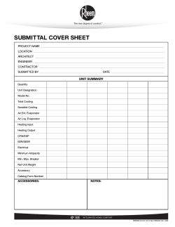


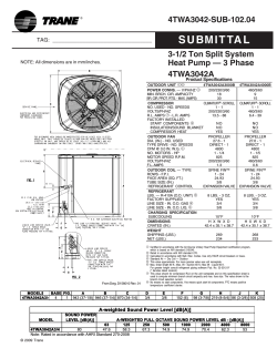

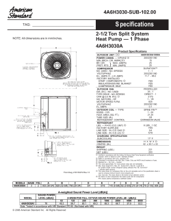

© Copyright 2026