
- OTC Asia
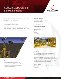
Thank you Greg….
1
• The topics I will briefly cover, are;
• Stack Configurations
• Wellhead Connector Considerations
• Control Systems
• Tensioning Systems will be discussed by Mr. Muhammad Sadiq, however in short, I would like to discuss a few points that should be considered in the design of the system. All connecting points must be symmetrically positioned, providing equal distribution of the load. The tensioning ring may also be incorporated into the telescopic joint. In the case of DP operations, the tensioning arrangement must also allow for heading changes. In addition, top tensioning may be applied to the BOP stack frame. In this case the load is not transmitted directly through the BOP. The BOP frame is designed, in such a way, to withstand the tensioning load as the BOP rests on the frame assembly.
• Many older generation drilling units may not be capable of providing the minimum required tension. In order to satisfy the requirement, there are a few alternatives available:
1 Upgrade existing tensioning system
2 Use a purpose‐built buoyed riser in conjunction with the (casing) riser system
3 Combination of upgraded tensioning system and purpose‐built buoyed riser
4 Deploy an air can buoy in the riser string
2
Each of these alternatives have their advantages and disadvantages.
• And lastly, time permitting would like to touch on air gap considerations
2
• Whilst both 13‐5/8” and 18‐3/4” and 10,000psi and 15,000psi BOP’s can be and have been successfully used for surface stack operations from floating rigs, however, the smallest size BOP is preferable due to its lower weight and ease of handling. Although, in saying that, the use of the existing subsea BOP may be utilized as a surface type BOP. The size of the rig’s moon pool, vessel motion and tensioning capacity are considerations in the selection of the BOP.
3
• The Seabed Isolation Device serves as the second barrier, providing the capability to shut‐in the well in the event of an emergency such as a catastrophic failure of the riser. This device is operated via an acoustic control system and/or via ROV intervention.
4
• A conventional style wellhead connector (Vetco H4/Cameron Collet or similar) installed below the surface BOP to connect to the riser through the upper riser mandrel/wellhead, with an upper riser mandrel/wellhead flanged to the top of the upper stress joint is the preferred method of connection.
• This use of a hydraulic connector provides a more efficient means to nipple‐up the BOP. • The benefits of the upper riser mandrel/wellhead are; 1. Provides an efficient means to nipple‐up the BOP being capable of accepting the hydraulic connector.
2. Serves as the connection between the surface BOP and the riser. It has a profile to accept the connector in use below the BOP. If the drilling program requires surface casing tiebacks, then the mandrel/wellhead will be capable of accommodating conventional casing hangers and seal assemblies. 3. Allows for landing a test plug to facilitate testing the BOP while connected to the riser.
• Seabed Isolation Device Connectors – The Seabed Isolation Device can be fitted with an Upper and Lower Hydraulic style such as Vetco H4/Cameron Collet.
The upper connector is mounted to the Seabed Isolation Device in the inverted position to serve as the connection between the Seabed Isolation Device and the riser to allow for re‐entry into the well or changing to a higher pressure rated riser.
5
• The rig’s existing control system can be utilized
• The control pod can be mounted on the stack or a suitable termination point on the BOP frame. Jumper hoses are used to connect from this termination to a POD receptacle mounted on the deck.
• Functions can be operated the same as when in conventional subsea mode.
• The primary means of control for the Seabed Isolation Device as previously
mentioned, is the acoustic control system, with the ROV serving as the back up control system.
• All functions on the Seabed Isolation Device can be operated by the ROV through use of the ROV intervention panel. In addition, the ROV must be capable of recharging the Seabed Isolation Device’s accumulator bottles as well as deploying and recovering the acoustic control transducers.
6
• The air gap considerations we refer to, is the height between the top of the BOP stack assembly and the bottom of the Diverter Ball/Flex Joint. This gap, is accommodated by means of a telescopic joint.
• The design of the telescopic joint must allow for sufficient stroke to withstand the maximum vessel excursion in the event of one mooring line failure in addition to accommodating maximum vessel heave and tidal changes.
• When selecting the style of connections for the telescopic joint we should consider the rig’s existing equipment. • The top connection needs to adapt to the existing diverter ball/flex joint connection. • The bottom connection can be an API flange connection, to interface directly with the top of the annular preventer. Alternatively, a mandrel can be flanged to the top of the annular preventer to facilitate the use of a standard marine riser coupling that can be assembled much quicker than an API flange.
7
Does anyone have any questions on what we have just covered?
8


© Copyright 2026