
USERS MANUAL FOR TEN TEC OMNI VII RADIO PAN ADAPTER
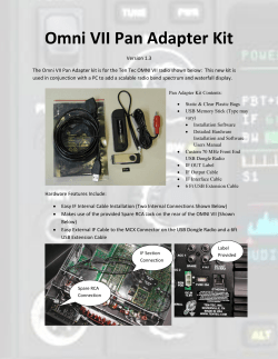
USERS MANUAL FOR TEN TEC OMNI VII RADIO PAN
ADAPTER USING HDSDR 2.70 SOFTWARE
(By AA3YW)
Version 1.3d
5/2/2015
Table of Contents
1.
2.
Hardware Installation ............................................................................................................................ 4
1.1.
Step 1 Top Cover Removal ........................................................................................................... 4
1.2.
Step 2 Cable F Installation ............................................................................................................ 5
1.3.
Step 3 IF Output Connector .......................................................................................................... 7
1.4.
Step 4 Dongle Radio Connection .................................................................................................. 8
Software Installation ............................................................................................................................. 8
2.1.
Step 5 OmniVII_Pan1R3d Software Installation .......................................................................... 8
2.2.
Step 6 Zadig Software Installation ................................................................................................ 9
2.3.
Step 7 CAT to Radio (Omni-Rig) Setup ..................................................................................... 10
2.4.
Step 8 Optional CAT to Radio (Ham Radio Deluxe) Setup ....................................................... 11
2.5.
Step 8 HDSDR Calibration & Settings Verification ................................................................... 12
2.6.
HDSDR Software Calibration Tasks .......................................................................................... 13
2.7.
Operating HDSDR ...................................................................................................................... 16
2.7.1.
Adjusting Display Area Size ............................................................................................... 16
2.7.2.
Adjusting Computer's Audio Bandwidth ............................................................................ 17
2.8.
Alignment of the radio Frequency to the Spectrum Display ....................................................... 17
2.9.
Soundcard Selection.................................................................................................................... 18
2.10.
Input Selection ........................................................................................................................ 19
2.11.
Input Channel Mode Selection................................................................................................ 20
2.12.
CAT To Radio Control .............................................................................................................. 22
List of Figures
Figure 1 Pan Adapter Kit Contents ................................................................................................................ 4
Figure 2 RCA Spare Connector Interface TMP Connection ........................................................................... 5
Figure 3 Insulated Pass-Through ................................................................................................................... 5
Figure 4 IF Section TMP Connection Point .................................................................................................... 6
Figure 5 Plugged In IF TMP Connector .......................................................................................................... 6
Figure 6 Completed Cable F Connection....................................................................................................... 7
Figure 7 IF OUT Label Placement .................................................................................................................. 7
Figure 8 IF OUT Cable Connected ................................................................................................................. 8
Figure 9: Eleventh Installation Dialog Box .................................................................................................... 9
Figure 10B: Bulk-IN, Interface (Interface 0) Selection .................................................................................. 9
Figure 11: HDSDR Main Screen ................................................................................................................... 10
Page 2 of 28
Figure 12: Omni-Rig Setup .......................................................................................................................... 10
Figure 13: Omni-Rig Setting Dialog Box ...................................................................................................... 11
Figure 14: Optional Ham Radio Deluxe Setup............................................................................................. 11
Figure 15: HDR Transmit Setup ................................................................................................................... 12
Figure 16: Sampling Bandwidth Dialog Box ................................................................................................ 13
Figure 17: ExtIO Activation ......................................................................................................................... 13
Figure 18: ExtIO Dialog Box ......................................................................................................................... 14
Figure 19: Options Dialog Box ..................................................................................................................... 14
Figure 20: Input Channel Calibration .......................................................................................................... 15
Figure 21: RF Front-End Calibration ............................................................................................................ 15
Figure 22: Windows Devices and Printer Installed Drivers ......................................................................... 16
Figure 23: Adjusting Frequency and Signal Gain......................................................................................... 17
Figure 24: Spectrum Offset Adjustment ..................................................................................................... 18
Figure 25: Sound Card Dialog Box ............................................................................................................... 18
Figure 26: Select Input Options................................................................................................................... 19
Figure 27: Visualization Settings ................................................................................................................. 19
Figure 28: FFT Selection .............................................................................................................................. 19
Figure 29: FFT Display Type......................................................................................................................... 19
Figure 30: Timestamp Selection.................................................................................................................. 19
Figure 31: Input I/Q Selection ..................................................................................................................... 20
Figure 32: AF Channel Selection ................................................................................................................. 20
Figure 33: Input Channel Calibration .......................................................................................................... 20
Figure 34: Misc Option Selection ................................................................................................................ 20
Figure 35: First Installation Dialog Box ....................................................................................................... 24
Figure 36: Second Installation Dialog Box ................................................................................................... 25
Figure 37: Third Installation Dialog Box ...................................................................................................... 25
Figure 38: Fourth Installation Dialog Box.................................................................................................... 26
Figure 39: Fifth Installation Dialog Box ....................................................................................................... 26
Figure 40: Sixth Installation Dialog Box....................................................................................................... 27
Figure 41: Seventh Installation Dialog Box ................................................................................................. 27
Figure 42: Eight Installation Dialog Box ...................................................................................................... 28
Figure 43: Ninth Installation Dialog Box ..................................................................................................... 28
Page 3 of 28
1. Hardware Installation
Kit Contents:
The Omni VII Pan Adapter kit shown in Figure 1 is used to extract the radio's 70 MHz IF signal
from the IF section and route it out to the spare RCA connectors in the rear of the radio. The
other connection to Omni VII is the serial output used to sync and control the radio's frequency,
volume and many other controls discussed later in this manual.
Pan Adapter Kit Contents:
F
E
G
C
A. Static & Clear Plastic
Bags
B. USB Memory Stick (Type
may vary)
C. USB Dongle Radio
D. IF OUT Label
E. IF Output Cable
F. IF Interface Cable
G. 6 Ft USB Extension Cable
B
A
D
Figure 1 Pan Adapter Kit Contents
1.1. Step 1 Top Cover Removal
Remove the radio's top cover by removing the side large screws and the screws on the
back edge of the cover. Remove the top cover, be careful of the speaker cable that
plugs into the interface board in the rear of the radio. The speaker can be damaged very
easily, so remove the connector and fish the connector and wires through the insulated
holes to remove the cover completely. The speaker connector is shown in Figure 2 and
Figure 3.
Page 4 of 28
Rear RCA connector TMP
Female Connection for the center
bottom row RCA connector
Speaker
Connector
Cable F Male TMP IF connection
Plugged into the Rear Female
TMP connector
Figure 2 RCA Spare Connector Interface TMP Connection
Insulated Passthrough
Figure 3 Insulated Pass-Through
1.2. Step 2 Cable F Installation
Insert one end of cable F's Male TMP connectors into the Female TMP connector on
the rear interface board as shown in Figure 2. Fish the other end of cable F with the
other Male TMP through the insulated hole pass-through shown in Figure 3 into the IF
section of the radio. Plug this end into the IF section Female TMP connector as shown
in Figure 4 and Figure 5. Figure 6 shows the completed internal wiring of cable F.
Page 5 of 28
Figure 4 IF Section TMP Connection Point
Plugged-In IF
TMP Connector
Figure 5 Plugged In IF TMP Connector
Page 6 of 28
Cable F
Completed
Figure 6 Completed Cable F Connection
1.3. Step 3 IF Output Connector
Remove the backing on the IF OUT label and place the adhesive label over top of the
lower bottom middle SPARE text as shown in Figure 7. Plug the RCA connector end
of the IF output cable E into the new IF OUT connector. Plug the speaker connector
back into it's connection point as shown in Figure 2 and replace the cover and all the
screws. This complete the internal work in the Omni VII.
Figure 7 IF OUT Label Placement
Page 7 of 28
1.4. Step 4 Dongle Radio Connection
Plug the IF Out cable that's connected to the radio's IF output to the dongle radio's
MCX connector as shown in Figure 8. Plug the dongle radio's USB connector into the
extended cable and into your computer's USB connector or plug the dongle radio
directly into the computer. Next connect the Omni VII's serial port to your computer
directly or through a USB adapter to control the Omni VII DB9 serial port connector.
This Completes the hardware setup.
Dongle radio's MCX
connection
USB to PC Computer and
Item G extension cable
Figure 8 IF OUT Cable Connected
2. Software Installation
Note! Please make sure your PC is not downloading or installing
updates when installing the OmniVII_Pan1R3d software. Also please
plug-in the USB Dongle Radio before starting the software installation!
2.1. Step 5 OmniVII_Pan1R3d Software Installation
Please read this manual before installing the OmniVII_Pan1R3d software. When finished
reading the manual insert the USB Dongle radio as well as the USB memory stick provided.
Double Click on the setup program OmniVII_Pan_1R3d.exe in the root of the provided USB
memory stick and install the SDR software and components. This will install the WinUSB
drivers and all other necessary files. The installer will preinstall all the initial settings except
your RIG under the HDSDR - Options - CAT to Radio (Omni-Rig) or Optional Ham Radio
Deluxe detailed below on page 10. Also there will be several message boxes that will pop up
during installation click OK and or accept each message. Should it become necessary to
reinstall the HDSDR program only instructions are on pages 24-28.
Page 8 of 28
List All Devices
Down Arrow
Replace Driver
Figure 9: Eleventh Installation Dialog Box
2.2. Step 6 Zadig Software Installation
This is the most critical step in the installation process. The Zadig dialog box will start
automatically during the installation (shown in Figure 9) and the correct USB driver must be
installed. Click the Options and enable "List All Devices", then click on the down arrow
YOU MUST choose either the Bulk-In, Interface (Interface 0) first if this first and press
"Install Driver" when it appears. If the first selection does not work then select Bulk-In,
Interface (Interface 1) press "Install Driver" again. If reinstallation is needed select
RTL2832U-device if listed and reinstall it.
Figure 10B: Bulk-IN, Interface (Interface 0) Selection
If either of these driver selections are not listed, please press the X in the upper
right hand corner of this dialog box. This will cancel the driver installation.
Do not choose any other selections! Do not select replace driver and again
cancel the driver installation.
Contact Three Rivers Embedded Systems, Inc. Phone: 724-353-1127 and we'll help you
through the driver installation.
When complete remove the USB Memory stick when the pop-up message box indicates to
reboot your computer. If a blank USB memory stick is in the computer, the PC may think it
is a boot drive and you'll get an error message saying that there is no operating system
installed. Don't panic remove the USB memory and reboot the computer.
Page 9 of 28
Start the HDSDR software by double clicking the HDSDR icon on the desktop or in the
windows menu.
Figure 11: HDSDR Main Screen
2.3. Step 7 CAT to Radio (Omni-Rig) Setup
Next the Rig interface needs to be selected to control the Omni VII's frequency. Click on
CAT to Radio (Omni-Rig) then Omni-Rig Setup as shown in Figure 12 and select the Omni
VII as the radio as shown in Figure 13. The port setting will depend on your computer's
COM port availability. The Omni VII has serial COM port output and if your computer has
only USB ports then a USB converter will be needed, which is common with most Laptop
PCs today. MS Windows Notebooks can also be used if they have a USB port. Verify that
the sync to Rig 1 set to the Omni VII, select sync to and from Omni-Rig and sync
Modulation are checked.
Select Setup
Figure 12: Omni-Rig Setup
Page 10 of 28
Check in the Windows Devices and Printers under the start
button for the correct COM port number for either the
USB to RS232 converter or the RS232 Serial Port COM
number. You can also check in the device manager under
COM Ports for the correct COM port. Figure 12 shows the
correct Baud rate 56000, 8,N,1 both RTS and DTR should
be set to High. Polling and Timeout should be set to
500ms. Click OK after correct setup.
Figure 13: Omni-Rig Setting Dialog Box
2.4. Step 8 Optional CAT to Radio (Ham Radio Deluxe) Setup
If you choose to use HRD as the Rig interface to control the Omni VII's frequency. HRD
must be installed setup and turned on before starting HDSDR! Start HDSDR Go to
Options==>CAT to Radio (Omni-Rig) and unselect both Sync to Omni Rig options. Then
select Omni-Rig Setup and select NONE as the radio. Next in Options under RF Front End Calibration menu under SDR on IF Output, which is controlled select By HRD (DDE). Click
on Options DDE to HRD then select HDR manual connect and OK as shown in Figure 14.
The status: should be Green and show Connection OK!
Select HRD and
Manual Connect
then OK
Figure 14: Optional Ham Radio Deluxe Setup
A manual "reconnection" maybe required on slower PCs when first starting HRD and HDSDR
to correct any sync issues. Faster PCs do not have this issue.
Page 11 of 28
Next optional Rig transmit using HDR . HRD must be installed setup and turned on before
starting HDSDR! Start HDSDR Click on Options TX then Click next to the Enable TX for
HRD DDE to put a check mark next to it and Click next to the Mute Audio on Transmit to
put a check mark next to it as shown in Figure 15. Click on Options to close this selection
box. Then HDR selection should be all setup.
Figure 15: HDR Transmit Setup
2.5. Step 8 HDSDR Calibration & Settings Verification
Select TX and
Check Enable TX
for HRD DDE and
Mute RX
Since this software is being setup up for the Ten Tec Omni VII radio a number of
calibration tasks need to be verified before proper operation can be achieved. These
calibration tasks are preinstalled and listed below and should be checked. Note! This
manual is designed to quickly get you started only. Some experimentation will be needed
to set up the system to exactly what you want.
Page 12 of 28
2.6. HDSDR Software Calibration Tasks
Set the receive sampling rate in the Bandwidth dialog box to input 12,000 and the output to
12,000 as shown in Figure 16. These settings affect the visible bandwidth of the spectral
display and the audio quality. Adjust them to your own liking.
Figure 16: Sampling Bandwidth Dialog Box
Set the ExtIO by Double Clicking (selecting) the
light blue to the right side of the TUNE Frequency
display as shown in Figure 15 . If this button is not
light blue the ExtIO.dll file is corrupted or missing
from the HDSRD directory see the troubleshooting
section to resolve this problem. Set the sampling
rate at 1.2MHz then both Tuner AGC and RTL
AGC as shown in Figure 18. The frequency
correction is for crystal temperature calibration to
adjust drift if any adjustment is needed. This
should only be set after 1 hour of operation.
ExtIO Light Blue
Figure 17: ExtIO Activation
Page 13 of 28
Figure 18: ExtIO Dialog Box
Verify that the Swap I and Q Channel for RX Input from the Options button shown in
Figure 19. This setting aligns the radio frequency position to the correct display spectrum
position.
Figure 19: Options Dialog Box
Next in the same options dialog box click the Mode button and select "Auto" then the OK
button as shown in Figure 20.
Page 14 of 28
Figure 20: Input Channel Calibration
In the same options dialog box select RF front-end frequency options & Calibration and as a
starting point set the options and selections as shown in Figure 21. The SDR IF must be
selected then the IF frequency must be set to 70MHz. Depending on the radio's IF frequency
a Global Offset may be necessary this radio needed an offset of 7570 to align the displayed
frequency to spectrum. There also needs additional offsets to be set per mode of operation as
shown. No other settings are necessary in this dialog box. Select apply and then click on the
X in the upper right hand corner to close this box. Note! these additional offsets align the
second receiver audio output in the computers audio to the Omni VII's receive audio. A
constant radio signal such as WWV can be used as a radio source on each band and mode.
Some adjustment maybe required for your system. For spectrum display only the settings in
Figure 21 are only a start and are covered in more detail in section 2.8 below.
Figure 21: RF Front-End Calibration
Page 15 of 28
If using a USB converter the installer will indicate which port the converter was installed
too in this case the PC Port is COM 10. Another way to find out the proper COM port is
to look at the PCs control panel under Hardware and Sound, Devices and Printers. Note!
The Prolific USB to Serial Port driver and the RTL2832U dongle radio drivers.
Figure 22: Windows Devices and Printer Installed Drivers
That completes the initial HDSDR software setup. The next steps will be to fine tune
the operation of HDSDR to your desired settings.
Additional information can be found at the HDSDR home website at
http://www.hdsdr.de but there's not a lot of documentation. The program has tooltips of
its own, but a few of them only display for a fraction of a second on my computer.
There's also a how to at http://www.hdsdr.de/howto, and an FAQ at
http://www.hdsdr.de/faq.html.
Click "Start" on the HDSDR menu or press F2.
2.7. Operating HDSDR
Now the HDSDR should be displaying band and frequency information such as in Figure 23.
The frequency responds in the HDSDR lower Tune display to adjustment of the radio's
frequency and the radio responds to frequency adjustment in the HDSDR lower Tune display
using the mouse to raise or lower the frequency. The spectrum slide adjustments shown in
Figure 23 adjust the displayed signal level and vary with band conditions, so you will always
be adjusting these levels to suite your needs. Experiment with all of the settings. The RBW is
the resolution bandwidth of the displayed spectrum. Typically I set this setting to 4.6 in LSB
and an average of 2, this is a display speed setting and is up to the user. All these setting are
for visual comfort.
2.7.1. Adjusting Display Area Size
The top waterfall and spectrum display sizes can be adjusted by right clicking and
holding down on the frequency bar and sliding the display up or down. As you
Page 16 of 28
move the mouse curser up and down the display area the curser will change to
cross arrows where this needs to be done.
2.7.2. Adjusting Computer's Audio Bandwidth
The computers audio filter bandwidth can be adjusted by click with the mouse in
the lower audio display area's red lines on either side of the filter display area
where the curser changes to a double arrow and slide the line in either direction to
increase or decrease the filter's bandwidth.
Frequency
Tune Display
Spectrum
Adjustment
Figure 23: Adjusting Frequency and Signal Gain
The audio section sliders work the same as the frequency display sliders, but adjust the
lower audio frequency display in Hz the level and waterfall. Note right clicking on the
audio spectrum name changes the audio spectrum display type. Left clicking on the
waterfall name turns off the waterfall sliders for each section.
2.8. Alignment of the radio Frequency to the Spectrum Display
The alignment of the Tune frequency to the spectral display require listening to the PC's
sound card and the Omni VII's audio output to compare the two sound outputs on each
mode as shown in Figure 24. Start out with 20 meters and USB mode, adjust the Global
offset to align the USB to the proper sound on both outputs. The suggestion is to leave
the USB mode offset set to zero. In adjusting things back and forth I ended up with a
700 Hz offset. You can go back to the Global offset and readjust it so that the USB
mode offset is 0. However, for demonstration purposes I choose to show that the exact
number in these mode offsets need not be exact. As long as the PC and Omni VII
sounds agree the spectrum display will be accurate. Each Omni VII could have a
different set of mode offset numbers depending on user setup and radio IF circuit
variations. All of the mode offsets need not be set at one time, set up a couple of your
favorite modes first and fine tune them in, then do the rest as time permits.
Page 17 of 28
Options (F7) -> RF front-end Calibration
Figure 24: Spectrum Offset Adjustment
2.9. Soundcard Selection
The soundcard in your computer also has a setup menu, however the default settings are
usually correct unless there are multiple soundcards in your computer. You can select
the soundcard using the dialog box shown in Figure 24, if your computer has multiple
soundcards and you have a specific card to use with this application.
Option (F5) ->Soundcard
Figure 25: Sound Card Dialog Box
Page 18 of 28
2.10.
Input Selection
On the right in Figure 25 are the choices under Select Input for visualization. The top 3
choices have more details below. The other selections are simple options for the
displaying visual data and are not covered in detail.
Options (F7) -> Select Input
Options (F7) -> Visualization
Figure 27: Visualization Settings
Figure 26: Select Input Options
Note! "Swap Spectrum/Waterfall Position" is turned on in Figure 26. The audio spectrum and
waterfall can be turn off by unchecking "Show Lower Display" if desired. The sliders are for
zooming the RF spectrum, which is hard to live without.
FFT Windowing
Color Palette
Waterfall Timestamp
Figure 29: FFT Display Type
Figure 30: Timestamp Selection
Figure 28: FFT Selection
Left to right in Figure 26 FFT Windowing You can play with this, but unless you're into higher
math the names probably won't mean much to you. FFT is Fast Fourier Transform or the way
time domain signals get transformed into frequency domain spectra like that in Figure 23. Some
people may have strong preferences but there's not a lot of difference.
Page 19 of 28
Color Palette in Figure 29 Different signal strengths get mapped to different colors, and the
palette controls what level gets mapped to what color. It's mostly just an aesthetic choice.
Waterfall Timestamp in Figure 30 Can easily be turned them off by selecting RF or AF off. You
can put them on the left or right sides of the waterfalls the preference is left of off.
2.11.
Input Channel Mode Selection
Input Channel Mode Output Channel Mode
for RX
for RX
Figure 31: Input I/Q
Selection
Input Channel Calibration for RX
Figure 32: AF Channel
Selection
Figure 33: Input Channel Calibration
Input Channel mode for RX dialog box. With the use of a dongle radio that puts out I/Q signals
so there's only one choice that really applies. I (Left) / Q (Right) and AF to Both channels.
Options(F7) -> Misc Options
Figure 34: Misc Option Selection
Misc Options shown if Figure 34: This is a list of things, most of which don't have their own
dialog boxes to show here. Most of these options are self explained.
Page 20 of 28
Autostart:
If this is turned on, HDSDR will automatically start when opened, without clicking the
start button.
set LO <-> Tune Offset:
When you do Quicktune, etc. by typing a frequency
out of the blue then clicking the MHz button, this is
how far offset the LO is from the frequency you
typed in.
Tune Fixed to 'LO <;-> Tune Offset:
This effectively binds the LO frequency and the tune frequency together, with the offset
above between them.
S-Meter calibration:
This setting can effectively turn
HDSDR into a field strength meter.
In theory this could be used for
comparing antennas, preamps, coax
runs, etc.
Lock Volume:
I can see why you'd want to lock the volume, but with a dongle radio this doesn't seem to
do anything other than create a visual cue. You might want to lock the volume if you're
feeding audio into another program.
Show Time in UTC:
This sets the display time to "UTC" on the screen after the date and time.
Normal Process Priority (default)
High Process Priority:
This is only useful if you've got marginal CPU power . Windows can get downright
sluggish and unresponsive running something at a high process priority. Usually patience
is a better alternative.
Show Status:
Page 21 of 28
Nothing to change here except locking your
downsampler ratio.
Reset to Factory Settings:
The panic button. In any piece of software this complex there are bound to be times
where something gets messed up and you maybe lose control. You just want to reset. But
resets often reset more than you want, so just to get a feel for what it does try it early on
before you get a lot customized.
2.12.
CAT To Radio Control
CAT to Radio (Omni-Rig)
CAT to HDSDR
DDE Client
CAT to Radio (Omni-Rig) Omni-Rig is the radio to computer interface that is used with the Ten
Tec Omni VII. There is an ExtIO_RTL2832.dll installed in the HDSDR directory. Select OmniRig setup and select the Ten Tec Omni VII radio shown in Figure 13. Select all the other setting
as shown in this Figure 13. The Enable TX Button for Rig 1 is currently not active and will be
activated at a later date. This button is only used for tuning the radio and could be used later for
digital applications. The mute RX audio on TX is also currently not working and will be
corrected at a later date.
CAT to HDSDR These are the settings for using Omni-Rig to control HDSDR and your SDR
hardware. To Omni-Rig your computer would look like an another radio.
Having the same capability for having Hamlib control HDSDR could be quite interesting, given
the variety of SDR hardware that HDSDR can control. Hamlib has no real user interface, but it
Page 22 of 28
can be driven by Fldigi and Gpredict among others. There are also beginnings of control over a
TCP/IP connection in both Hamlib and Fldigi.
Recording Settings/Scheduler
Recording Settings/Scheduler:
This dialog box is a very useful recording and scheduling function. You can schedule recording
satellite passes, nets, anything you might otherwise miss. If the recording mode is set to RF, a
giant wav file will contain everything within the covered RF spectrum range, which can be
decoded later.
Not covered:
In the spectrum display there are 2 vertical lines shown. The left is the tune frequency. The right
one, with the frequency and db value attached, moves with your mouse. If you click the tune
frequency moves there.
Make sure that the IQ Swap is set correctly. Ensure that SSB signals are on the correct sideband
and that tuning is correct, that higher frequencies ARE actually to the right.
Note if you have not set "Options - Channel Skew Calibration" (Image rejection) you will see
images on strong signals. Do not be confused.
Options - Channel Skew (Image Rejection) Calibration
This shows the important TX image rejection panel seen when in transmit mode. The RX panel is similar.
"Sample Delay" is only needed for a few, mainly old Creative, soundcards.
This page https://sites.google.com/site/g4zfqradio/hdsdr-iq-balance gives full details.
Page 23 of 28
The HDSDR and Zadig software is shareware and offered free of charge with no warranty or
implied warranty. Three Rivers Embedded Systems, Inc. will provide software support at phone
number 724-353-1127 or contact [email protected]. The OmniVII Pan hardware has a 1
year warranty.
The following information is for reference should the HDSDR software reinstall be needed.
If the HDSDR software needs to be installed by itself do not reinstall the OmniVII_Pan1R3.exe again.
Go to the OmniVII Pan folder on your C drive and run the HDSDR_Install.exe. Then follow Figures 3240 to complete the HDSDR software installation.
Press or click on the Next Button.
Note! If you have the User Account
Control turned on you will need to
click on accept when flagged.
Figure 35: First Installation Dialog Box
Page 24 of 28
Click on the "I accept the agreement"
button.
Figure 36: Second Installation Dialog Box
Click or press the next button to
proceed with the installation.
Figure 37: Third Installation Dialog Box
Page 25 of 28
Select the location where you want to
install the HDSDR or/then press or
click Next to proceed with the
installation.
Figure 38: Fourth Installation Dialog Box
Press or click Next to proceed with the
installation. Again if user account
control is turned on windows will
continue to ask permission to install
this application. Just click accept to
continue.
Note! Watch your tool bar for a yellow
warning message asking permission.
Figure 39: Fifth Installation Dialog Box
Page 26 of 28
Select where you want your HDSDR
icon to show up then press or click
Next to proceed with installation.
Figure 40: Sixth Installation Dialog Box
Press or click on the install button to
proceed with the installation.
Figure 41: Seventh Installation Dialog Box
Page 27 of 28
Click on the check mark to deselect
the start HDSDR, because there are
more components to install and setup
before you start the HDSDR
application.
Figure 42: Eight Installation Dialog Box
Then Press or click on the Finish
button to continue with the
installation.
Figure 43: Ninth Installation Dialog Box
Page 28 of 28


© Copyright 2026