
Review of Air-Coupled Transduction for
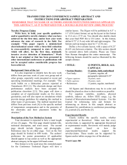
Review of Air-Coupled
Transduction for
Nondestructive Testing
and Evaluation
Marcel C. Remillieux,
Brian E. Anderson,
T. J. Ulrich,
Pierre-Yves Le Bas,
Michael R. Haberman
and Jinying Zhu
Emails:
[email protected]
[email protected]
[email protected]
[email protected]
Postal:
Geophysics Group (EES-17)
MS D446
Los Alamos National Laboratory
Los Alamos, New Mexico 87545
Email:
[email protected]
Postal:
Applied Research Laboratories
The University of Texas at Austin,
Austin, Texas 78713
Email:
[email protected]
Postal:
Department of Civil, Architectural
and Environmental Engineering
The University of Texas at Austin
Austin, Texas 78712
36 | Acoustics Today | Summer 2014
The future of nondestructive testing lies in the ability to efficiently generate
waves in structures without contact.
Introduction
Nondestructive testing (NDT) of structures and mechanical parts is increasingly
receiving attention as the need to monitor the health of aging infrastructure and
quality controls on the manufacturing of mechanical parts is becoming more apparent. NDT is defined as using various tools, whether they be acoustic, electromagnetic, or thermally based, to inspect the structural integrity of these objects
without damaging the object as a result of testing it. In the case of acoustic NDT
techniques, a source transducer emits sound/vibrational waves into the structure
under test and various techniques are then used to detect signatures of damage
(such as micro or macro cracking, etc.).
In 1996, Delta Flight 1288 experienced engine failure when part of a fan hub entered the engine; this accident led to the death of two passengers. It was later determined that undetected micro-fractures missed during routine maintenance were
the cause of the failure (Federal Aviation Administration, 2014). In 2002, a Boeing
747 operated by China Airlines catastrophically failed in flight, causing the death
of 206 passengers and 19 crew members. The probable cause was the growth of
incipient fractures, created during a previous noncritical accident that went undetected (Federal Aviation Administration, 2014). NDT techniques detected cracking and corrosion on the I-35W Mississippi River bridge in Minnesota prior to its
collapse in 2007, yet measures were not taken to avoid the collapse that led to the
deaths of 13 people (Wikipedia, 2014). In 2012, 16 workers at the Idaho National
Laboratory were exposed to radioactive powder as a result of damaged stainlesssteel cladding that housed the radioactive material (Associated Press, 2011). Each
of these accidents, and many others, could likely have been avoided with the use of
proper NDT techniques, along with appropriate intervention measures.
The vibration of solid structures for NDT, without contacting the structure, offers
many advantages. As bonding between the source transducer and the structure
is eliminated, along with the use of noncontact sensors (such as laser Doppler vibrometers and/or microphones), rapid imaging of large areas then becomes possible. Besides, it is not always desirable or feasible to use contact transducers on
certain samples. The development of efficient air-coupled transducers, however,
remains a challenge because of the large impedance contrast, by several orders of
magnitude, between air and solids. Impedance is the product of the speed of sound
and the density of the material or medium.
When there is a significant impedance change between two “Developments in the next generation
different media, in this case nearly 5 orders of magnitude of air coupled sources, that utilize
difference between the face of the source transducer and the
time-reversal focusing or a focused
air, it is difficult to deliver energy into the air from the transducer’s motion. Practically, this means that only a fraction of electric spark source, will provide
the energy generated by the source will be transmitted into more reliable excitation with higher
the air and then only a fraction will be transmitted to the
amplitudes and allow the use of adstructure. Essentially, nothing can be done about the impedance mismatch between the air and the structure under test. vanced NDT techniques.”
Fortunately, a number of approaches have been proposed to
improve the transmission of energy from the source into the aerogel (Krauss et al., 1994), silicone rubber loaded with
air. Noteworthy reviews on this topic include the paper of micro-spheres (Yano et al., 1987), and porous membranes
Green (2004) and the recent one of Chimenti (2014). Both (Kelly et al., 2001). Most of these materials have impedances
focus on non-contact transduction devices while the latter close to 0.1 MRayl and relatively low attenuation. Note that
also discusses the implementation of several NDT tech- silica aerogel is limited to applications below 100 kHz beniques. The present paper provides an overview of recent cause it does not lend itself to machining at the thickness
advances on the development of air-coupled transducers for that would be required for higher frequency applications. A
NDT applications, with some new techniques that are not detailed review of the materials used in the design of matchreported in either of the aforementioned papers, and a brief ing layers, including their attenuation, impedance, and perreview of many traditional types of air-coupled transduc- formance, is given by Gómez Álvarez-Arenas (2004). The
tion.
matching layer can also be created using micro-fabrication
techniques (Haller et al., 1994) for operating frequencies apConventional Non-Contact Sources
proaching 1 MHz. The main disadvantage of using a single
Most commonly, generation of ultrasonic waves inside a matching layer is the reduced bandwidth and the subsequent
material through air is achieved with piezoelectric transduc- ringing of the transducer. To address this limitation, the use
ers that are manufactured from a bulk piece of ceramic. A of multiple layers has been proposed, where the intermedipiezoelectric material is characterized by its ability to con- ate layers increase the bandwidth with a reduced effect on
vert electric energy into mechanical energy, and vice versa. the sensitivity (Goll et al., 1975; Desilets et al., 1978).
The large impedance contrast between the piezoelectric material and air can be mitigated with resonant matching layers Alternatives to matching layers have been proposed to enthat are glued onto the surface of the transducer and that ba- hance the ultrasonic radiation of bulk piezoelectric transsically act as an impedance transition between the piezoelec- ducers. Multiple ultrasonic horns obtained by chemical
tric material and the air. Initial work on the design of such etching on a plate have been tested in the range of 20 to 100
layers suggested a single layer with two characteristics: (1) kHz (Fletcher and Thwaites, 1992). Another strategy has
a thickness of one quarter of a wavelength at the resonance been to reduce the impedance of the active element through
frequency of the transducer so that a standing wave can be the use of composites made of ceramic pillars embedded
established across the layer; and (2) an impedance close to in a uniform filler material (such as epoxy) matrix (Reilly
the geometrical mean of the impedances of the piezoelectric and Hayward, 1991; Smith and Auld, 1991). The mechanimaterial and the medium the source is radiating into (Lyn- cal properties of the composite can be adjusted with the
nworth, 1965). For air-coupled applications, the impedance volume fraction of ceramic. Impedance matching has also
of the matching layer should range between 0.001 and 0.1 been achieved by constraining a thin layer of air between
MRayl (Haller et al., 1994). Many porous materials with im- the surface of the piezoelectric element and a thin polymer
pedances approaching this range, including cork and balsa membrane or a perforated plate (Toda, 2002). Last, some rewood, cannot be used as matching layers because they ex- cent numerical work has suggested the possibility of using
hibit high attenuation, which deteriorates the performance wedges of power-law profiles to provide a gradual impedof the transducer (Schiller et al., 1994; Stor-Pellinen et al., ance matching (Remillieux et al., 2014). Ideally, for a perfect
1989). Practical materials for this application include silica wedge tip with no thickness, these profiles ensure that the
| 37
Review of Air-Coupled Transduction for
Nondestructive Testing and Evaluation
elastic waves generated within the thickest portion of the
wedge (or adjacent plate) by a bulk piezoelectric transducer
propagate towards the wedge tip and never reflect back from
it. In practice, the wedge tip has a finite thickness and reflects some of the energy back into the wedge. Despite this
imperfection, power-law profiles provide a smooth impedance matching transition for the large-amplitude flexural
waves observed in the thinnest region of the wedge (near
the wedge tip), thus improving significantly the ultrasonic
radiation in air. The experimental validation of this numerical work is underway.
Capacitive ultrasonic transducers are an alternative to bulk
piezoelectric transducers. They were introduced in the
1950s (Kuhl et al., 1954). Their principle of operation is radically different from that of piezoelectric transducers. They
typically consist of two components: (1) a fixed electrode - a
conducting back plate with a microscopically rough surface
of random profile; (2) an electrode allowed to deform - a
thin dielectric polymer membrane coated on one side with
a conducting layer and stretched over the back plate. A bias
voltage is applied so that the oppositely charged electrodes
attract. As a result, the membrane is stretched further and
remains in contact with the back plate. Because of the varying surface profile of the back plate, the membrane is resting on point-like supports and small air gaps are formed beneath the membrane. Under a voltage signal, the membrane
deforms and displaces the surrounding fluid, which generates ultrasonic waves. The transducer can also be used as a
receiver under the reciprocal process. Capacitive ultrasonic
transducers offer two advantages over piezoelectric transducers: a better impedance matching with air and a wider
bandwidth (Schindel, 1996). Their performance depends
mainly on the dimensions of the air gaps, the membrane
properties (such as density, dimensions), and the bias voltage
(Carr and Wykes, 1993). At high frequencies, such as above
1 MHz, it is not possible to control the size of the air gaps
beneath the membrane through traditional manufacturing
techniques. The subsequent variation of the membrane tension across its surface leads to reduced performance of the
transducer.
The advent of micro-fabrication techniques led to the rapid
development, since the late 1980s, of capacitive micromachined ultrasonic transducers (CMUTs). The interested
reader is referred to the review of Khuri-Yakub and Oralkan
(2011) on this topic. Microfabrication techniques provide
control over the parameters for which there were uncertain38 | Acoustics Today | Summer 2014
ties in traditional
capacitive ultrasonic
transducers:
inplane tension and
air-gap size. Additionally, the reduction of the membrane and air-gap
sizes allows reaching
higher frequencies,
in the tens of MHz,
Figure 1: Photographs of MUT arrays. which was not pos(a) CMUT provided by Prof. Butrus sible previously. A
(Pierre) Khuri-Yakub from Stanford photograph of a
University. (b) PMUT provided by Dr.
CMUT array is deArman Hajati from FUJIFILM Dimatix.
picted in Figure 1a.
The operating principle of CMUTs is identical to that of traditional capacitive
ultrasonic transducers. However, there are three practical issues with CMUTs: (1) the bias voltage must be close to the
collapse voltage to achieve the theoretical electromechanical
coupling, which is not possible given the current tolerances
in micro-fabrication techniques; (2) the design must be different for optimal transmitting and receiving operations:
a small air gap is required to increase sensitivity when the
CMUT is used as a receiver whereas the relatively large displacement of the membrane in a transmitter requires a much
larger air gap; and (3) they have a small capacitance (large
electrical impedance), thus making their operation sensitive
to parasitic capacitances. To minimize the effect of parasitic
capacitance and to limit the potential of interference on the
cabling, the transmitter/receiver electronics should be kept
close to the CMUT elements (ideally integrated on a single
chip).
Piezoelectric micromachined ultrasonic transducers
(PMUTs) are an alternative to CMUTs that still benefit from
micro-fabrication techniques for miniaturization and precision control but do not need a conducting back plate to be
operated. A photograph of a PMUT array is shown in Figure
1b. Essentially, they consist of an electroded thin piezoelectric film deposited on a (possibly multilayered) membrane
resonator, which is typically on the order of microns in
the thickness and tens of microns in the in-plane direction
(Akesheh et al., 2004). An electric field is applied across the
thickness of the piezoelectric film, which in turn induces
a deformation of the membrane according to its bending
modes. The piezoelectric film is used as an actuating element
only while the ultrasonic radiation characteristics (such as
operating frequency) are dictated by the membrane properties. Other advantages over CMUTs include: (1) a higher
capacitance, which makes the transducer less vulnerable to
parasitic capacitances and the use of coaxial cables possible;
(2) lower power requirements due to the elimination of the
bias voltage; and (3) lower sensitivity to fabrication accuracy. It is worth mentioning that PMUTs do not offer a perfect
alternative to CMUTs as the deposition of a high quality thin
piezoelectric film, free of defects, remains a challenge and
therefore, an active topic of research. Defects in the thin film
may include micro-cracks, pinholes, lattice misorientation,
and non-uniform thickness.
Ultrasonic arrays of transducers have been increasingly
preferred over single-element transducers because, when
combined with appropriate signal processing techniques,
they offer many attractive features, including some flexibility in the type of ultrasonic fields generated (such as plane
waves, steered beams, and focused excitation) and better
imaging capabilities. An extensive review on this topic for
NDT applications, including transducer materials and array
geometries, is given by Drinkwater and Wilcox (2006), with
a particular focus on the phased array technology. The operation of phased arrays is based on the use of appropriate
time delays between the signals applied to or received from
the individual transducers. When parabolic delays are used,
ultrasonic waves can be focused to a specific point in air or
on the surface of a sample (Azar et al., 2000). This allows
reaching relatively high amplitude levels at the focal point
compared to what a single-element transducer can generate.
The performance of a phased array is not only affected by
transducer material and signal processing but also by its geometry. Initially, arrays were one-dimensional, which means
that their elements were aligned along a linear axis and
beams could be steered only in the plane formed by the axis
of the array and the normal to the surfaces of the transducers.
Simplification of the electronics and availability of cheaper
hardware has spurred the development of two-dimensional
arrays in which the elements are usually arranged in a checkerboard format. This added dimension allows three-dimensional steering. Annular arrays are the third type of arrays
commonly encountered. They consist of a set of concentric
rings with varying width so as to keep the surface area of
each element constant. They allow the beam to be focused
to different depths but only along the normal to the array
surface passing through its center. One important aspect to
consider when designing the array is the spacing between
the elements. If the element spacing is larger than one half of
a wavelength (λ/2) at the operating frequency used for beam
steering or focusing, then grating lobes will be generated.
Grating lobes are essentially undesired side lobes resulting
from the spatial under-sampling of periodically arranged elements. Usually, the λ/2 limitation can be overcome by keeping the gap between the elements small while increasing the
width of the element. As the element shape deviates from a
point-like representation, its radiation becomes more directional and the contribution of the grating lobes is reduced
but so is the range of angles at which beams can be steered.
Another conventional technique for non-contact transduction is based on the thermoelastic effect. White (1963) demonstrated that the thermal expansion resulting from transient heating on the surface of a solid generates elastic waves
within the solid, which is referred to as the thermoelastic effect. Pulsed lasers are commonly used for this purpose since
they can create a focused excitation in space and time. The
amplitude of the excitation is related to the energy density.
If it becomes too large, material ablation may occur as a result of the melting and evaporation of the material in the
area targeted by the laser. The effect of the heating rate was
studied by Gauster (1971). The depth of the damage is on the
order of a few microns. This may not be acceptable in some
NDT applications. In this case, the pulsed laser should be
operated within the thermoelastic regime, such as below the
threshold of ablation. Typically, for NDT applications, the
pulse duration approaches 10 ns, which provides a broadband perturbation with frequency content up to 100 MHz
(Viertl, 1980). Pulsed lasers have been used to excite different types of waves in structures. Despite many advantages,
the operation of a pulsed laser requires high power and appropriate safety measures to be taken. Therefore, it does not
have the same practicality as air-coupled sources.
Time Reversal Acoustic
Non-Contact Excitation
A high amplitude acoustic source has been developed at the
Los Alamos National Laboratory (LANL) using the principle of reciprocal time reversal (TR) to focus energy in time
and space on the surface of a sample without contact (Le
Bas et al., 2013). A prototype of this source is depicted in
Figure 2. The hardware essentially consists of a hollow cavity
enclosed by thin metallic walls onto which some piezoelectric transducers are glued. The size(s) of the transducers will
| 39
Review of Air-Coupled Transduction for
Nondestructive Testing and Evaluation
Figure 2: The high-amplitude non-contact acoustic source based on reciprocal
TR installed in front of a test sample: (a)
drawing and (b) photograph of the experimental apparatus.
Figure 3: Comparison of energy focusing on the surface of a thin metallic plate achieved with
a Focused Ultrasound Transducer (left) and the TR non-contact source (right). Spatial extent
of the focal spot in terms of wavelength (top) and time histories of the velocity at the focal point
(bottom).
determine the optimal operating frequencies of the source.
The cavity creates a diffusely scattered wave field inside and
contains an opening to allow a progressive emission of the
scattered waves. The cavity has two holes in order to shine a
laser vibrometer through it. The elastic response recorded
by the laser at a point on the surface of the test sample is
used to calibrate the source to focus energy at that point,
as will be described below. The larger hole at the top of the
pyramid is also the main sound transmission path from the
source to the sample. Note that, in a TR experiment, scattering is beneficial to the ability of focusing energy in time
and space because each reflection acts as a virtual source. In
other words, a TR experiment can be conducted successfully
with only one transducer as long as the medium is highly
reverberant and weakly dissipative. This is clearly an advantage over phased arrays where scattering would deteriorate
the performance of the array.
A standard TR experiment in a reverberant medium consists of two steps that can be briefly summarized as follows
(Anderson et al., 2008). In the first step, or forward propagation, a known signal is emitted from a source at a point
40 | Acoustics Today | Summer 2014
A while a receiver is recording the signal at a point B. The
received signal is the convolution of the impulse response
between points A and B with the source signal. This impulse
response is rather complex due to the multiple propagation
paths within the bounded medium. In the second step, or
backward propagation, the received signal is reversed in time
and remitted from point B. The invariance of the wave equation implies that the various broadcasts of energy from each
virtual source will coalesce at point A, where the original
source signal will be reconstructed (Fink, 1992). There are
some imperfections in this reconstruction process, mainly
because the directional information of the energy received
in the forward signals is not typically used, attenuation that
exists in a realistic system, and a limited (as opposed to infinite) acquisition time of the forward-propagation signal
is used. It is possible to interchange the source and the receiver positions thanks to the principle of spatial reciprocity (Achenbach, 2003). In the backward-propagation step of
a reciprocal TR experiment, the received signal is remitted
from the source point A and coalesces at the receiver point B.
Experiments were conducted on a thin metallic plate (Figure
2) and the performance of the LANL source was compared
to that of a commercially available Focused Ultrasound
Transducer (FUT) that makes use of impedance matching
layers and some geometry optimization. Figure 3 shows the
velocity fields on the plate at an instant in time and the signals recorded at the focal point location. One advantage of
the LANL source is the ability to generate only one distinct
large amplitude pulse of energy whereas the FUT repeatedly
produces pulses of energy due to the multiple reflections between the surface of the FUT and that of the test sample.
The size of the focal spot is approximately five times smaller
with the LANL source than with the FUT. Last, the LANL
source also offers a significant gain of amplitude, in this case
a factor eight times. Note that this gain was obtained with a
prototype device that was not optimized in any way and that
was built for the purpose of demonstrating that the concept
was working. Optimization studies are under way. In particular, the effects of the wall thickness, layout of the transducers, and shape of the cavity are investigated. An additional
gain of amplitude is expected from an optimized device.
Last, it is worth mentioning that the spot size (measured
as full width at half maximum) achieved by a TR mirror in
the far field cannot be smaller than half a wavelength as a
consequence of the diffraction limit. Sub-wavelength components of the acoustic field cannot be recovered by TR in
the far field of a homogeneous medium because they are carried by evanescent waves, which decay exponentially with
the distance from the source. The diffraction limit can be
overcome by using, for instance, a distribution of scatterers
with specific sizes in the near field of the source, to achieve
sub-wavelength focusing (Lerosey et al., 2007). Evanescent
waves convert to propagating waves as they diffract off the
scatterers.
Focused Electric Spark Source
Focusing can also be achieved by appropriately tuning the
shape of the transducer: usually with an ellipsoidal shape.
This strategy has been used for bulk piezoelectric transducers that are combined with impedance matching layers
(Bhardwaj, 2001), with capacitive ultrasonic transducers
(Song et al., 2006), and spark sources (Dai et al., 2013). The
performance of the first type of focused transducer has been
discussed in the previous section, in comparison with that of
the LANL source (TR mirror). The second type of focused
transducer can achieve diffraction-limited focusing, like the
TR mirror. The third type is discussed in more details below,
Figure 4: (a) Schematic representation of the test setup including the
spark source enclosed within the ellipsoidal reflector and (b) peak
pressure amplitude versus distance along axis, measured by a hydrophone and a microphone. Hydrophone sensing was employed near
the focus to enable measurement of high amplitudes without saturation (overloading).
since it is a new apparatus that is neither based on bulk piezoelectric transducers nor capacitive ultrasound transducers.
Recent efforts at The University of Texas (UT) at Austin have
been focused on the generation of high amplitude air-borne
acoustic signals for non-contact excitation of wave motion
in concrete slabs to aid in the rapid inspection of the nation’s infrastructure (Dai et al., 2013). The non-contact aircoupled NDT device devised by UT is schematized in Figure
4 and consists of a spark generator and an ellipsoidal focusing mirror. The spark generator consists of two electrodes
separated by a small air gap which is collocated with the near
focus of the ellipsoidal reflector. A high electric potential is
generated across the electrodes of the spark generator by
charging a large capacitor that is electrically in parallel with
the electrodes. Discharge occurs when the electric field between the electrodes reaches a critical level and the ensuing
spark creates a rapid and intense heating of the air resulting in a high amplitude acoustic disturbance that spreads
outward with nearly omnidirectional directivity. This transient wave spherically diverges from the near focus until it
encounters the ellipsoidal reflector, when it is then reflected
and re-directed back to the far focus. The reflected wavefront
| 41
Review of Air-Coupled Transduction for
Nondestructive Testing and Evaluation
converges at the far focus where the amplitude is proportional to the time-derivative of the spark-generated signal
and some gain factor related to the geometry of the reflector
(Hamilton, 1993). Because the spark-generated wave has a
very short rise-time, and thus a high temporal derivative, the
peak pressures at the far focus are very high and thus capable
of generating elastic waves in the sample to be interrogated.
In-air peak pressures as high as 180 dB re 20 μPa at the farfocus have been measured (Dai et al., 2013).
It is important to point out that the use of spark-generated
signals to generate high amplitude acoustic waves is nothing new. Indeed, Wright and Blackstock (1997) used sparkgenerated signals to study on-axis wave field resulting from
spark-generated air-borne N-waves that were focused by an
ellipsoidal reflector. Further, use of a spark discharges for
ultrasonic NDT has also been explored with some success
(Cooper et al., 1984; Korolev et al., 1987). Those discharges
result in intense, transient, and localized heating at the surface of the sample and a subsequent high frequency ultrasonic signal with amplitudes similar to those generated by
pulsed lasers. This approach proved to be somewhat problematic, however, because numerous spark discharges on the
surface of the interrogated sample resulted in damage due
to ablation and thus alternative configurations were investigated.
Krylov and colleagues later investigated the use of air-borne
acoustic waves generated by in-air sparks with some encouraging results for generating elastic wave motion in aluminum. Their studies included un-focused (Krylov, 1992)
and spherically focused air-borne waves (Korolev and Krylov, 1988). Each of those had drawbacks which apparently
discouraged further study. Curiously, no results were ever
reported by Krylov and colleagues that employed an ellipsoidal reflector paired with spark-generated acoustic waves
which enables wave focusing without requiring collocation
of the source and focus points.
The ultrasonic source developed at UT has been used for
impact-echo testing in concrete plates. This technique (impact-echo) consists of impulsively loading the surface of the
plate, usually via contact such as a hammer blow, and recording the out-of-plane motion. The spectrum of the response contains a peak corresponding to the impact-echo
frequency, which is proportional to the compressional wave
speed in the material and inversely proportional to the sample thickness (Sansalone and Carino, 1986). Recent analysis
has shown that these impact-echo frequencies are associ42 | Acoustics Today | Summer 2014
Figure 5: Spectra showing the zero-group-velocity mode in a 25cm
thick concrete plate measured using contact sensing and fully noncontact methods with spark-source excitation (Dai et al., 2013).
ated with zero-group-velocity (ZGV) Lamb modes that represent localized wave motion with non-zero phase velocity
but zero group velocity and have high excitability (Gibson
and Popovics, 2005; Prada et al., 2008). Because these modes
have zero-group velocity, they represent wave motion that
is trapped near the source point and thus is long lived and
relatively easy to detect.
Theoretical and experimental work at UT shows that the
focused spark-generated air-borne signal has a sufficiently
small spot size on the air-solid interface that broadband surface waves can be generated in concrete and detected using
accelerometers on the surface (contact sensing) or microphones positioned close to the surface (non-contact sensing), as seen in Figure 5 for the case of a 25 cm thick concrete
plate. The results clearly show that a spark-generated signal
focused by an ellipsoidal reflector enables fully air-coupled
interrogation of the surface of a specimen with high acoustic impedance. Other work exploiting the properties of ZGV
modes was based on the use of traditional air-coupled ultrasonic transducers (Holland and Chimenti, 2004) and pulsed
laser excitation (Cès et al., 2011).
Conclusion
Nondestructive testing (NDT) is increasingly relied upon for
monitoring aging infrastructure and for evaluating transportation structures. Air-coupled (non-contact) transduction allows rapid testing of these structures and thus increases the practicality of NDT implementation. Developments
in the next generation of air coupled sources, that utilize
time-reversal focusing or a focused electric spark source,
will provide more reliable excitation with higher amplitudes
and allow the use of advanced NDT techniques.
Biosketches
Marcel Remillieux is a post-doctoral
research associate at Los Alamos National Laboratory. He is developing,
implementing, and using numerical
techniques to solve elastodynamic
problems with applications to nondestructive testing. Between 2005
and 2012, he conducted research on
NASA funded projects at Virginia
Tech, where he received his M.S. and
Ph.D. degrees in mechanical engineering. He also holds an
Engineer Diploma in mechanical engineering from the Université de Technologie de Compiègne, France. During his
undergraduate education, he was selected for a year-long
exchange program with the University of Pennsylvania (Ivy
League). Since that time, he has been mostly living in the
United States and has been enjoying most of his vacations
in France. In his free time, Marcel enjoys outdoor activities,
skiing being his favorite, in New Mexico with his family.
Brian Anderson is a research scientist at Los Alamos National Laboratory (LANL) in the Geophysics
Group where he develops new nonlinear acoustic techniques, using
time reversal, for the nondestructive
evaluation of mechanical parts and
structures. He is an associate editor
for the Journal of the Acoustical Society of America. Prior to coming to
LANL, Brian spent 3 years as a visiting assistant professor
at Brigham Young University (BYU) in the Dept. of Physics
& Astronomy conducting research and teaching courses. He
worked for three years as a postdoctoral research associate
at LANL. He received a Ph.D. in Acoustics from the Pennsylvania State University in 2006 while working at the Applied Research Laboratory there. He received his M.S. and
B.S. degrees in Physics from BYU. Brian enjoys GPS-based
geocaching in his spare time with his three sons and his wife
Angela.
TJ Ulrich has been conducting research using time reversal and nonlinear elasticity at Los Alamos National Laboratory (LANL) for the
past 10 years, first as a post-doc and
now as a research scientist. During
this time he has developed many
international collaborations and enjoys traveling the world to work on
various topics on acoustics, nondestructive evaluation, and materials characterization. Prior
to coming to LANL, TJ attended the University of Nevada,
Reno where he obtained degrees in Materials Science and
Engineering (B.S.) and Physics (M.S. and Ph.D.). His current
research focus is developing the next generation of acoustic
tools for nondestructive evaluation of mechanical parts and
structures, specifically for nuclear energy applications, as
well as geophysical exploration tools and techniques for the
oil and gas industry. When at all possible you can find TJ at
his home away from home on the slopes of Taos Ski Valley
with his family or down in town enjoying the blue corn and
green chile.
Pierre-Yves Le Bas is currently a research scientist at Los Alamos National Laboratory. He obtained his
Ph.D. in acoustics from the University of Le Havre, France in 2004.
Pierre-Yves was one of the experimentalists in a European project
called AERONEWS where he developed NDE techniques combining
Time Reversal and nonlinear elasticity during a post-doc at
KU Leuven, Belgium. His work includes the use of nonlinear
acoustic techniques for nondestructive evaluation and borehole imaging. He is a certified LabVIEW architect for developing experimental systems. Pierre-Yves enjoys mentoring
the Los Alamos High School FIRST robotics team, project Y.
Biosketches continued on next page.
| 43
Review of Air-Coupled Transduction for
Nondestructive Testing and Evaluation
Michael R. Haberman received his
B.S. degree in Mechanical Engineering from the University of Idaho in
2000 and his M.S. and Ph.D. degrees
in mechanical engineering from
the Georgia Institute of Technology
in 2001 and 2007, respectively. Dr.
Haberman also earned a Diplôme de
Doctorat in engineering mechanics
from Université Paul Verlaine (currently Université de la Lorraine) in Metz, France, in 2006.
He is a Research Scientist at both Applied Research Laboratories and the Department of Mechanical Engineering
at UT Austin. His research interests are centered on elastic
and acoustic wave propagation in complex media, acoustic
metamaterials, new transduction materials, nondestructive
testing, and acoustic transducers. He is the recipient of 2012
ASNT Fellowship Award and serves as an Associate Editor
of the Journal of the Acoustical Society of America.
Jinying Zhu received her Ph.D. degree in civil engineering from the
University of Illinois at UrbanaChampaign, Illinois, USA, in 2006.
She is currently an assistant professor at the University of Texas at Austin. Her research interests focus on
developing rapid NDT techniques
for concrete structures, and characterizing cement material properties
using innovative sensors. She is the recipient of 2012 ASNT
Fellowship Award and three times winner of ACI-James Instruments Award (with graduate students).
References
Achenbach, J. D. (2003). Reciprocity in Elastodynamics (Cambridge University Press, Cambridge, UK).
Akasheh, F., Myers, T., Fraser, J. D., Bose, S., and Bandyopadhyay, A. (2004).
“Development of piezoelectric micromachined ultrasonic transducers,”
Sensors and Actuators A: Physical 111, 275–287.
Anderson, B. E., Griffa, M., Larmat, C., Ulrich, T. J., and Johnson, P. A.
(2008). “Time Reversal,” Acoustics Today 4, 5–16.
Associated Press, Idaho lab accident may stem from damaged container, Internet, last viewed May 8, 2014, http://examiner-enterprise.com/sections/
news/nation/idaho-lab-accident-may-stem-damaged-container.html.
Azar, L., Shi, Y., and Wooh, S.-C. (2000). “Beam focusing behavior of linear
phased arrays,” NDT & E International 33, 189–198.
44 | Acoustics Today | Summer 2014
Bhardwaj, M. C. “Ultrasonic transducer for high transduction in gases and
method for non-contact ultrasound transmission into solid materials,” US
Patent #6,311,573, November 6, 2001.
Carr, H., and Wykes, C. (1993). “Diagnostic measurements in capacitive
transducers” Ultrasonics 31, 13–20
Cès, M., Clorennec, D., Royer, D., and Prada, C. (2011) “Edge resonance
and zero group velocity Lamb modes in a free elastic plate,” Journal of the
Acoustical Society of America 130, 689–694.
Chimenti, D. E. (2014). “Review of air-coupled ultrasonic materials characterization,” Ultrasonics, in press.
Cooper, J. A., Dewhurst, R. J., Moody, S., and Palmer, S. B. (1984). “Highvoltage spark discharge source as an ultrasonic generator,” IEE Proceedings A. Physical Science, Measurement and Instrumentation, Management and Education, Reviews 131, 275–281.
Dai, X., Zhu, J., and Haberman, M. R. (2013). “A focused electric spark
source for non-contact stress wave excitation in solids,” Journal of the
Acoustical Society of America 134, EL513–EL519.
Desilets, C. S., Fraser, J. D., and Kino, G. S. (1978). “The design of efficient
broad-band piezoelectric transducers,” IEEE Transactions on Sonics and
Ultrasonics 25, 115–125.
Drinkwater, B. W., and Wilcox, P. D. (2006). “Ultrasonic arrays for nondestructive evaluation: A review,” NDT & E International 39, 525–541.
Federal Aviation Administration, Lessons learned from airplane accidents,
Internet, last viewed May 8, 2014, http://lessonslearned.faa.gov/ll_main.cf
m?TabID=3&CategoryID=7&LLID=60.
Federal Aviation Administration, Lessons learned from airplane accidents,
Internet, last viewed May 8, 2014, http://lessonslearned.faa.gov/ll_main.cf
m?TabID=3&CategoryID=7&LLID=6.
Fink, M. (1992). “Time reversal of ultrasonic fields – Part I: Basic principles,” IEEE Transactions on Ultrasonics, Ferroelectrics and Frequency
Control 39, 555–566.
Fletcher, N. H., and Thwaites, S. (1992). “Multi-horn matching plate for ultrasonic transducers,” Ultrasonics 30, 67–75.
Gauster, W. B. (1971). “Effect of heating rate in thermoelastic stress production,” Journal of the Mechanics and Physics of Solids 19, 137–145.
Gibson, A., and Popovics, J. S. (2005) “Lamb wave basis for impact-echo
method analysis,” Journal of Engineering Mechanics 131, 438–443.
Goll, J. H., and Auld, B. A. (1975). “Multilayer impedance matching
schemes for broadbanding of water loaded piezoelectric transducers and
high Q electric resonators,” IEEE Transactions on Sonics and Ultrasonics
22, 52–53.
Gómez Álvarez-Arenas, T. E. (2004). “Acoustic impedance matching of
piezoelectric transducers to the air,” IEEE Transactions on Ultrasonics,
Ferroelectrics and Frequency Control 51, 624–633.
Green Jr., R. E. (2004). “Non-contact ultrasonic techniques” Ultrasonics 42,
9–16.
Haller, M. I., and Khuri-Yakub, B. T. (1994). “Micromachined 1–3 composites for ultrasonic air transducers,” Review of Scientific Instruments 65,
2095–2098.
Krauss, O., Gerlach, R., and Fricke, J. (1994). “Experimental and theoretical
investigations of SiO2-aerogel matched piezo-transducers,” Ultrasonics
32, 217–222.
Hamilton, M. F. (1993). “Transient axial solution for the reflection of a
spherical wave from a concave ellipsoidal mirror,” Journal of the Acoustical
Society of America 93, 1256–1266.
Holland, S. D., and Chimenti, D. E. (2004) “High contrast air-coupled
acoustic imaging with zero group velocity Lamb modes,” Ultrasonics 42,
957–960.
Kelly, S. P., Hayward, G., and Gómez, T. E. (2001). “An air-coupled ultrasonic matching layer employing half wavelength cavity resonance,” Proceedings IEEE Ultrasonic Symposium, 965–968.
Khuri-Yakub, B. T., and Oralkan, Ö. (2011). “Capacitive micromachined
ultrasonic transducers for medical imaging and therapy,” Journal of Micromechanics and Microengineering: Structures, Devices, and Systems 21,
055004–055014.
Korolev, S. V., Krasil’nikov, V. A., and Krylov, V. V. (1987). “Mechanism of
sound generation in a solid by a spark discharge near the surface,” Soviet
Physics – Acoustics 33, 451–452.
Korolev, S. V., and Krylov, V. V. (1988). “Efficient excitation of Rayleigh
waves by a strong shock wave initiated by a spark in air,” Soviet Technical
Physics Letters 14, 843–845.
Krylov, V. V. (1992). “On the theory of surface acoustic wave generation
by electric spark discharge,” Journal of Physics D: Applied Physics 25,
155–161.
Kuhl, W., Schodder, G. R., and Schröder, F.-K. (1954). “Condenser transmitters and microphones with solid dielectric for airborne ultrasonics,”
Acustica 4, 519–532.
Le Bas, P.-Y., Ulrich, T. J., Anderson, B. E., and Esplin, J. J. (2013). “A high
amplitude, time reversal acoustic non-contact excitation (trance),” Journal
of the Acoustical Society of America 134, EL52–EL56.
Lerosey, G., de Rosny, J., Tourin, A., and Fink, M. (2007). “Focusing beyond the diffraction limit with far-field time reversal,” Science 315, 1120–
1122.
Lynnworth, L. C. (1965). “Ultrasonic impedance matching from solid to
gas,” IEEE Transactions on Ultrasonics, Ferroelectrics and Frequency
Control 12, 37–48.
Prada, C., Clorennec, D., and Royer, D. (2008) “Local vibration of an elastic
plate and zero-group velocity Lamb modes,” Journal of the Acoustical Society of America 124, 203–212.
Reilly, D., and Hayward, G. (1991). “Through air transmission for ultrasonic non-destructive testing,” Proceedings IEEE Ultrasonic Symposium,
763–766.
Remillieux, M. C., Anderson, B. E., Le Bas, P.-Y., and Ulrich, T. J. (2014).
“Improving the air coupling of bulk piezoelectric transducers with wedges
of power-law profiles: A numerical study,” Ultrasonics 54, 1409–1416.
Sansalone, M., and Carino, N. J. (1986). “Impact echo: A method for
flaw detection in concrete using transient stress waves,” Report No.
NBSIR86-3452, National Bureau of Standards, Gaithersburg, MD.
Schiller S., Hsieh, C.-K., Chou, C.-H., and Khuri-Yakub, B. T. (1990). “Novel high-frequency air transducers,” Review of Progress in Quantitative
Nondestructive Evaluation 9, 795–798.
Schindel, D. W., Hutchins, D. A., and Grandia, W. A. (1996). “Capacitive
and piezoelectric air-coupled transducers for resonant ultrasonic inspection,” Ultrasonics 34, 621–627.
Smith, W. A., and Auld, B. A. (1991). “Modeling 1–3 composite piezoelectrics: Thickness-mode oscillations,” IEEE Transactions on Ultrasonics,
Ferroelectrics and Frequency Control 38, 40–47.
Song., J., Chimenti, D. E., and Holland, S. D. (2006). “Spherically focused
capacitive-film, air-coupled ultrasonic transducer,” Journal of the Acoustical Society of America 119, EL1–EL6.
Stor-Pellinen, J., Oksanen, M., Vuohelainen, R., Rantala, J., Hartikainen, J.,
and Luukkala, M. (1989). “Photoacoustic inspection of matching layers of
ultrasonic air-coupled transducers,” Proceedings IEEE Ultrasonic Symposium, 665–668.
Toda, M. (2002). “New type of matching layer for air-coupled ultrasonic
transducers,” IEEE Transactions on Ultrasonics, Ferroelectrics and Frequency Control 49, 972–979.
Viertl, J. R. M. (1980). “Frequency spectrum of laser-generated ultrasonic
waves,” Journal of Applied Physics 51, 805–807.
White, R. M. (1963). “Generation of elastic waves by transient surface heating,” Journal of Applied Physics 34, 3559–3564.
TUNE INTO ZERO’s
SOUND SOLUTIONS
ZERO is a world-wide leader in high-performance acoustical control
for doors, windows, walls or floors. Nobody does sound control better
— we use advanced technology and testing to master the challenges
of creating an effective barrier and preventing gaps in that barrier
for the life of the assembly. Our systems are rated for use in sound
studios, music halls, or where ever sound solutions are needed —
up to 55 STC. Let us help you close the door on noise — contact us
for a copy of our Sound Control brochure, and our 92 page Product
Catalog, or download from our website.
Phone: 1-800-635-5335 / 718-585-3230 • Fax: 718-292-2243
Email: [email protected] • www.zerointernational.com
NEED
WE
SAY
MORE...
@acousticsorg
Official twitter account
for Acoustics Today
www.acousticstoday.org
Wikipedia, I-35W Mississippi River bridge, Internet, last viewed May 8,
2014, http://en.wikipedia.org/wiki/I-35W_Mississippi_River_bridge.
Wright, W. M., and Blackstock, D. T. (1997). “Focusing of N waves in air by
an ellipsoidal reflector,” Journal of the Acoustical Society of America 102,
741–746.
Yano, T., Tone, M., and Fukumoto, A. (1987). “Range finding and surface
characterization using high-frequency air transducers,” IEEE Transactions
on Ultrasonics, Ferroelectrics and Frequency Control 34, 232–236.
| 45


© Copyright 2026