
33. Avalon Streaming Test Pattern Generator and Checker Cores Core Overview
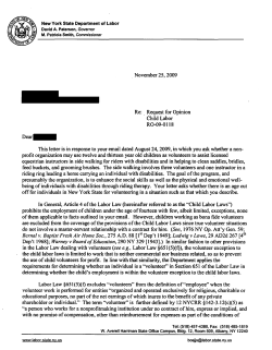
33. Avalon Streaming Test Pattern
Generator and Checker Cores
QII55007-9.1.0
Core Overview
The data generation and monitoring solution for Avalon® Streaming (Avalon-ST)
consists of two components: a test pattern generator core that generates packetized or
non-packetized data and sends it out on an Avalon-ST data interface, and a test
pattern checker core that receives the same data and checks it for correctness.
The test pattern generator core can insert different error conditions, and the test
pattern checker reports these error conditions to the control interface, each via an
Avalon Memory-Mapped (Avalon-MM) slave.
Both cores are SOPC Builder-ready and integrate easily into any SOPC
Builder-generated system.
This chapter contains the following sections:
■
“Resource Utilization and Performance”
■
“Test Pattern Generator” on page 33–3
■
“Test Pattern Checker” on page 33–5
■
“Device Support” on page 33–6
■
“Hardware Simulation Considerations” on page 33–6
■
“Software Programming Model” on page 33–7
■
“Test Pattern Generator API” on page 33–12
■
“Test Pattern Checker API” on page 33–16
Resource Utilization and Performance
Resource utilization and performance for the test pattern generator and checker cores
depend on the data width, number of channels, and whether the streaming data uses
the optional packet protocol.
© November 2009
Altera Corporation
Quartus II Handbook Version 9.1 Volume 5: Embedded Peripherals
33–2
Cores
Quartus II Handbook Version 9.1 Volume 5: Embedded Peripherals
Table 33–1 provides estimated resource utilization and performance for the test pattern generator core.
Table 33–1. Test Pattern Generator Estimated Resource Utilization and Performance
Stratix® II and Stratix II GX
Cyclone® II
Stratix
No. of
Channels
Datawidth
(No. of
8-bit
Symbols
Per Beat)
Packet
Support
fMAX
(MHz)
ALM
Count
Memory
(bits)
fMAX
(MHz)
Logic
Cells
Memory
(bits)
fMAX
(MHz)
Logic
Cells
Memory
(bits)
1
4
Yes
284
233
560
206
642
560
202
642
560
1
4
No
293
222
496
207
572
496
245
561
496
32
4
Yes
276
270
912
210
683
912
197
707
912
32
4
No
323
227
848
234
585
848
220
630
848
1
16
Yes
298
361
560
228
867
560
245
896
560
1
16
No
340
330
496
230
810
496
228
845
496
32
16
Yes
295
410
912
209
954
912
224
956
912
32
16
No
269
409
848
219
842
848
204
912
848
Table 33–2 provides estimated resource utilization and performance for the test pattern checker core.
© November 2009 Altera Corporation
No. of
Channels
Datawidth
(No. of
8-bit
Symbols
Per Beat)
Packet
Support
fMAX
(MHz)
ALM
Count
Memory
(bits)
fMAX
(MHz)
Logic
Cells
Memory
(bits)
fMAX
(MHz)
Logic
Cells
Memory
(bits)
1
4
Yes
270
271
96
179
940
0
174
744
96
1
4
No
371
187
32
227
628
0
229
663
32
32
4
Yes
185
396
3616
111
875
3854
105
795
3616
32
4
No
221
363
3520
133
686
3520
133
660
3520
1
16
Yes
253
462
96
185
1433
0
166
1323
96
Stratix II and Stratix II GX
Cyclone II
Stratix
1
16
No
277
306
32
218
1044
0
192
1004
32
32
16
Yes
182
582
3616
111
1367
3584
110
1298
3616
32
16
No
218
473
3520
129
1143
3520
126
1074
3520
Chapter 33: Avalon Streaming Test Pattern Generator and Checker
Table 33–2. Test Pattern Checker Estimated Resource Utilization and Performance
Chapter 33: Avalon Streaming Test Pattern Generator and Checker Cores
Test Pattern Generator
33–3
Test Pattern Generator
This section describes the hardware structure and functionality of the test pattern
generator core.
Functional Description
The test pattern generator core accepts commands to generate data via an Avalon-MM
command interface, and drives the generated data to an Avalon-ST data interface. You
can parameterize most aspects of the Avalon-ST data interface such as the number of
error bits and data signal width, thus allowing you to test components with different
interfaces. Figure 33–1 shows a block diagram of the test pattern generator core.
Figure 33–1. Test Pattern Generator Core Block Diagram
control & status
TEST PATTERN
GENERATOR
Avalon-ST
Source
command
Avalon-MM
Slave Port
Avalon-MM
Slave Port
data_out
The data pattern is determined by the following equation:
Symbol Value = Symbol Position in Packet XOR Data Error Mask. Non-packetized
data is one long stream with no beginning or end.
The test pattern generator core has a throttle register that is set via the Avalon-MM
control interface. The value of the throttle register is used in conjunction with a
pseudo-random number generator to throttle the data generation rate.
Command Interface
The command interface is a 32-bit Avalon-MM write slave that accepts data
generation commands. It is connected to a 16-element deep FIFO, thus allowing a
master peripheral to drive a number of commands into the test pattern generator core.
The command interface maps to the following registers: cmd_lo and cmd_hi. The
command is pushed into the FIFO when the register cmd_lo (address 0) is written to.
When the FIFO is full, the command interface asserts the waitrequest signal. You
can create errors by writing to the register cmd_hi (address 1). The errors are only
cleared when 0 is written to this register or its respective fields. See page “Test Pattern
Generator Command Registers” on page 33–9 for more information on the register
fields.
© November 2009
Altera Corporation
Quartus II Handbook Version 9.1 Volume 5: Embedded Peripherals
33–4
Chapter 33: Avalon Streaming Test Pattern Generator and Checker Cores
Test Pattern Generator
Control and Status Interface
The control and status interface is a 32-bit Avalon-MM slave that allows you to enable
or disable the data generation as well as set the throttle.
This interface also provides useful generation-time information such as the number of
channels and whether or not packets are supported.
Output Interface
The output interface is an Avalon-ST interface that optionally supports packets. You
can configure the output interface to suit your requirements.
Depending on the incoming stream of commands, the output data may contain
interleaved packet fragments for different channels. To keep track of the current
symbol’s position within each packet, the test pattern generator core maintains an
internal state for each channel.
Instantiating the Test Pattern Generator in SOPC Builder
Use the MegaWizard™ interface for the test pattern generator core in SOPC Builder to
configure the core. The following sections list the available options in the
MegaWizard interface.
Functional Parameter
The functional parameter allows you to configure the test pattern generator as a
whole: Throttle Seed—The starting value for the throttle control random number
generator. Altera recommends a value which is unique to each instance of the test
pattern generator and checker cores in a system.
Output Interface
You can configure the output interface of the test pattern generator core using the
following parameters:
■
Number of Channels—The number of channels that the test pattern generator
core supports. Valid values are 1 to 256.
■
Data Bits Per Symbol—The number of bits per symbol for the input and output
interfaces. Valid values are 1 to 256. Example—For typical systems that carry 8-bit
bytes, set this parameter to 8.
■
Data Symbols Per Beat—The number of symbols (words) that are transferred per
beat. Valid values are 1 to 256.
■
Include Packet Support—Indicates whether or not packet transfers are supported.
Packet support includes the startofpacket, endofpacket, and empty signals.
■
Error Signal Width (bits)—The width of the error signal on the output interface.
Valid values are 0 to 31. A value of 0 indicates that the error signal is not used.
Quartus II Handbook Version 9.1 Volume 5: Embedded Peripherals
© November 2009 Altera Corporation
Chapter 33: Avalon Streaming Test Pattern Generator and Checker Cores
Test Pattern Checker
33–5
Test Pattern Checker
This section describes the hardware structure and functionality of the test pattern
checker core.
Functional Description
The test pattern checker core accepts data via an Avalon-ST interface, checks it for
correctness against the same predetermined pattern used by the test pattern generator
core to produce the data, and reports any exceptions to the control interface. You can
parameterize most aspects of the test pattern checker's Avalon-ST interface such as the
number of error bits and the data signal width, thus allowing you to test components
with different interfaces.
The test pattern checker has a throttle register that is set via the Avalon-MM control
interface. The value of the throttle register controls the rate at which data is accepted.
Figure 33–2 shows a block diagram of the test pattern checker core.
Figure 33–2. Test Pattern Checker
control & status
data_in
Avalon-ST
Sink
Avalon-MM
Slave Port
TEST PATTERN
CHECKER
The test pattern checker core detects exceptions and reports them to the control
interface via a 32-element deep internal FIFO. Possible exceptions are data error,
missing start-of-packet (SOP), missing end-of-packet (EOP) and signalled error.
As each exception occurs, an exception descriptor is pushed into the FIFO. If the same
exception occurs more than once consecutively, only one exception descriptor is
pushed into the FIFO. All exceptions are ignored when the FIFO is full. Exception
descriptors are deleted from the FIFO after they are read by the control and status
interface.
Input Interface
The input interface is an Avalon-ST interface that optionally supports packets. You
can configure the input interface to suit your requirements.
Incoming data may contain interleaved packet fragments. To keep track of the current
symbol’s position, the test pattern checker core maintains an internal state for each
channel.
© November 2009
Altera Corporation
Quartus II Handbook Version 9.1 Volume 5: Embedded Peripherals
33–6
Chapter 33: Avalon Streaming Test Pattern Generator and Checker Cores
Device Support
Control and Status Interface
The control and status interface is a 32-bit Avalon-MM slave that allows you to enable
or disable data acceptance as well as set the throttle. This interface provides useful
generation-time information such as the number of channels and whether the test
pattern checker supports packets.
The control and status interface also provides information on the exceptions detected
by the test pattern checker core. The interface obtains this information by reading
from the exception FIFO.
Instantiating the Test Pattern Checker in SOPC Builder
Use the MegaWizard interface for the test pattern checker core in SOPC Builder to
configure the core. The following sections list the available options in the
MegaWizard interface.
Functional Parameter
The functional parameter allows you to configure the test pattern checker as a whole:
Throttle Seed—The starting value for the throttle control random number generator.
Altera recommends a unique value to each instance of the test pattern generator and
checker cores in a system.
Input Parameters
You can configure the input interface of the test pattern checker core using the
following parameters:
■
Data Bits Per Symbol—The number of bits per symbol for the input interface.
Valid values are 1 to 256.
■
Data Symbols Per Beat—The number of symbols (words) that are transferred per
beat. Valid values are 1 to 32.
■
Include Packet Support—Indicates whether or not packet transfers are supported.
Packet support includes the startofpacket, endofpacket, and empty
signals.
■
Number of Channels—The number of channels that the test pattern checker core
supports. Valid values are 1 to 256.
■
Error Signal Width (bits)—The width of the error signal on the input interface.
Valid values are 0 to 31. A value of 0 indicates that the error signal is not in use.
Device Support
The test pattern generator and checker cores support all Altera© device families.
Hardware Simulation Considerations
The test pattern generator and checker cores do not provide a simulation testbench for
simulating a stand-alone instance of the component. However, you can use the
standard SOPC Builder simulation flow to simulate the component design files inside
an SOPC Builder system.
Quartus II Handbook Version 9.1 Volume 5: Embedded Peripherals
© November 2009 Altera Corporation
Chapter 33: Avalon Streaming Test Pattern Generator and Checker Cores
Software Programming Model
33–7
Software Programming Model
This section describes the software programming model for the test pattern generator
and checker cores.
HAL System Library Support
For Nios II processor users, Altera provides HAL system library drivers that enable
you to initialize and access the test pattern generator and checker cores. Altera
recommends you to use the provided drivers to access the cores instead of accessing
the registers directly.
For Nios II IDE users, copy the provided drivers from the following installation
folders to your software application directory:
■
<IP installation directory> /ip /sopc_builder_ip /altera_avalon_data_source/HAL
■
<IP installation directory>/ip/sopc_builder_ip/ altera_avalon_data_sink/HAL
This instruction does not apply if you use the Nios II command-line tools.
Software Files
The following software files define the low-level access to the hardware, and provide
the routines for the HAL device drivers. Application developers should not modify
these files.
■
■
© November 2009
Software files provided with the test pattern generator core:
■
data_source_regs.h—The header file that defines the test pattern generator's
register maps.
■
data_source_util.h, data_source_util.c—The header and source code for the
functions and variables required to integrate the driver into the HAL system
library.
Software files provided with the test pattern checker core:
■
data_sink_regs.h—The header file that defines the core’s register maps.
■
data_sink_util.h, data_sink_util.c—The header and source code for the
functions and variables required to integrate the driver into the HAL system
library.
Altera Corporation
Quartus II Handbook Version 9.1 Volume 5: Embedded Peripherals
33–8
Chapter 33: Avalon Streaming Test Pattern Generator and Checker Cores
Software Programming Model
Register Maps
This section describes the register maps for the test pattern generator and checker
cores.
Test Pattern Generator Control and Status Registers
Table 33–3 shows the offset for the test pattern generator control and status registers.
Each register is 32 bits wide.
Table 33–3. Test Pattern Generator Control and Status Register Map
Offset
Register Name
base + 0
status
base + 1
control
base + 2
fill
Table 33–4 describes the status register bits.
Table 33–4. Status Field Descriptions
Bit(s)
Name
Access
Description
[15:0]
ID
RO
A constant value of 0x64.
[23:16]
NUMCHANNELS
RO
The configured number of channels.
[30:24]
NUMSYMBOLS
RO
The configured number of symbols per beat.
SUPPORTPACKETS
RO
A value of 1 indicates packet support.
[31]
Table 33–5 describes the control register bits
Table 33–5. Control Field Descriptions
Bit(s)
[0]
Name
Access
Description
ENABLE
RW
Setting this bit to 1 enables the test pattern generator core.
THROTTLE
RW
Specifies the throttle value which can be between 0–256, inclusively. This
value is used in conjunction with a pseudorandom number generator to
throttle the data generation rate.
[7:1]
[16:8]
Reserved
Setting THROTTLE to 0 stops the test pattern generator core. Setting it to
256 causes the test pattern generator core to run at full throttle. Values
between 0–256 result in a data rate proportional to the throttle value.
[17]
SOFT RESET
RW
When this bit is set to 1, all internal counters and statistics are reset. Write
0 to this bit to exit reset.
[31:18]
Reserved
Table 33–6 describes the fill register bits.
Table 33–6. Fill Field Descriptions (Part 1 of 2)
Bit(s)
[0]
Name
BUSY
Access
Description
RO
A value of 1 indicates that data transmission is in progress, or that there is
at least one command in the command queue.
[6:1]
Quartus II Handbook Version 9.1 Volume 5: Embedded Peripherals
Reserved
© November 2009 Altera Corporation
Chapter 33: Avalon Streaming Test Pattern Generator and Checker Cores
Software Programming Model
33–9
Table 33–6. Fill Field Descriptions (Part 2 of 2)
Bit(s)
[15:7]
Name
Access
RO
FILL
Description
The number of commands currently in the command FIFO.
[31:16]
Reserved
Test Pattern Generator Command Registers
Table 33–7 shows the offset for the command registers. Each register is 32 bits wide.
Table 33–7. Test Pattern Command Register Map
Offset
Register Name
base + 0
cmd_lo
base + 1
cmd_hi
Table 33–8 describes the cmd_lo register bits. The command is pushed into the FIFO
only when the cmd_lo register is written to.
Table 33–8. cmd_lo Field Descriptions
Bit(s)
Name
Access
Description
[15:0]
SIZE
RW
The segment size in symbols. Except for the last segment in a packet, the size
of all segments must be a multiple of the configured number of symbols per
beat. If this condition is not met, the test pattern generator core inserts
additional symbols to the segment to ensure the condition is fulfilled.
[29:16]
CHANNEL
RW
The channel to send the segment on. If the channel signal is less than
14 bits wide, the low order bits of this register are used to drive the signal.
[30]
SOP
RW
Set this bit to 1 when sending the first segment in a packet. This bit is ignored
when packets are not supported.
[31]
EOP
RW
Set this bit to 1 when sending the last segment in a packet. This bit is ignored
when packets are not supported.
Table 33–9 describes the cmd_hi register bits.
Table 33–9. cmd_hi Field Descriptions
Bit(s)
Name
Access
Description
[15:0]
SIGNALLED
ERROR
RW
Specifies the value to drive the error signal. A non-zero value creates a
signalled error.
[23:16]
DATA ERROR
RW
The output data is XORed with the contents of this register to create data
errors. To stop creating data errors, set this register to 0.
[24]
SUPRESS SOP
RW
Set this bit to 1 to suppress the assertion of the startofpacket signal
when the first segment in a packet is sent.
[25]
SUPRESS EOP
RW
Set this bit to 1 to suppress the assertion of the endofpacket signal
when the last segment in a packet is sent.
© November 2009
Altera Corporation
Quartus II Handbook Version 9.1 Volume 5: Embedded Peripherals
33–10
Cores
Chapter 33: Avalon Streaming Test Pattern Generator and Checker
Test Pattern Checker Control and Status Registers
Table 33–10 shows the offset for the control and status registers. Each register is 32 bits
wide.
Table 33–10. Test Pattern Checker Control and Status Register Map
Offset
Register Name
base + 0
status
base + 1
control
base + 2
base + 3
Reserved
base + 4
base + 5
exception_descriptor
base + 6
indirect_select
base + 7
indirect_count
Table 33–11 describes the status register bits.
Table 33–11. Status Field Descriptions
Bit(s)
Name
Access
Description
[15:0]
ID
RO
Contains a constant value of 0x65.
[23:16]
NUMCHANNELS
RO
The configured number of channels.
[30:24]
NUMSYMBOLS
RO
The configured number of symbols per beat.
SUPPORTPACKETS
RO
A value of 1 indicates packet support.
[31]
Table 33–12 describes the control register bits.
Table 33–12. Control Field Descriptions
Bit(s)
[0]
Name
ENABLE
Access
RW
Description
Setting this bit to 1 enables the test pattern checker.
[7:1]
[16:8]
Reserved
THROTTLE
RW
Specifies the throttle value which can be between 0–256, inclusively. This
value is used in conjunction with a pseudorandom number generator to
throttle the data generation rate.
Setting THROTTLE to 0 stops the test pattern generator core. Setting it to
256 causes the test pattern generator core to run at full throttle. Values
between 0–256 result in a data rate proportional to the throttle value.
[17]
SOFT RESET
RW
When this bit is set to 1, all internal counters and statistics are reset. Write
0 to this bit to exit reset.
[31:18]
Quartus II Handbook Version 9.1 Volume 5: Embedded Peripherals
Reserved
© November 2009 Altera Corporation
Chapter 33: Avalon Streaming Test Pattern Generator and Checker Cores
Software Programming Model
33–11
Table 33–13 describes the exception_descriptor register bits. If there is no
exception, reading this register returns 0.
Table 33–13. exception_descriptor Field Descriptions
Bit(s)
Name
Access
Description
[0]
DATA ERROR
RO
A value of 1 indicates that an error is detected in the incoming data.
[1]
MISSINGSOP
RO
A value of 1 indicates missing start-of-packet.
[2]
MISSINGEOP
RO
A value of 1 indicates missing end-of-packet.
[7:3]
[15:8]
Reserved
SIGNALLED
ERROR
RO
[23:16]
[31:24]
The value of the error signal.
Reserved
CHANNEL
RO
The channel on which the exception was detected.
Table 33–14 describes the indirect_select register bits.
Table 33–14. indirect_select Field Descriptions
Bit
[7:0]
Bits Name
Access
INDIRECT
CHANNEL
RW
Specifies the channel number that applies to the INDIRECT PACKET
COUNT, INDIRECT SYMBOL COUNT, and INDIRECT ERROR
COUNT registers.
INDIRECT
ERROR
RO
The number of data errors that occurred on the channel specified by
INDIRECT CHANNEL.
[15:8]
[31:16]
Description
Reserved
Table 33–15 describes the indirect_count register bits.
Table 33–15. indirect_count Field Descriptions
Bit
Bits Name
Access
Description
[15:0]
INDIRECT
PACKET COUNT
RO
The number of packets received on the channel specified by INDIRECT
CHANNEL.
[31:16]
INDIRECT
SYMBOL COUNT
RO
The number of symbols received on the channel specified by INDIRECT
CHANNEL.
© November 2009
Altera Corporation
Quartus II Handbook Version 9.1 Volume 5: Embedded Peripherals
33–12
Cores
Chapter 33: Avalon Streaming Test Pattern Generator and Checker
Test Pattern Generator API
This section describes the application programming interface (API) for the test pattern
generator core. All API functions are currently not available from the interrupt service
routine (ISR).
data_source_reset()
Prototype:
void data_source_reset(alt_u32 base);
Thread-safe:
No.
Include:
<data_source_util.h>
Parameters:
base—The base address of the control and status slave.
Returns:
void.
Description:
This function resets the test pattern generator core including all internal counters and FIFOs. The
control and status registers are not reset by this function.
data_source_init()
Prototype:
int data_source_init(alt_u32 base, alt_u32 command_base);
Thread-safe:
No.
Include:
<data_source_util.h>
Parameters:
base—The base address of the control and status slave.
command_base—The base address of the command slave.
Returns:
1—Initialization is successful.
0—Initialization is unsuccessful.
Description:
This function performs the following operations to initialize the test pattern generator core:
■
Resets and disables the test pattern generator core.
■
Sets the maximum throttle.
■
Clears all inserted errors.
data_source_get_id()
Prototype:
int data_source_get_id(alt_u32 base);
Thread-safe:
Yes.
Include:
<data_source_util.h>
Parameters:
base—The base address of the control and status slave.
Returns:
The test pattern generator core’s identifier.
Description:
This function retrieves the test pattern generator core’s identifier.
Quartus II Handbook Version 9.1 Volume 5: Embedded Peripherals
© November 2009 Altera Corporation
Chapter 33: Avalon Streaming Test Pattern Generator and Checker Cores
Test Pattern Generator API
33–13
data_source_get_supports_packets()
Prototype:
int data_source_init(alt_u32 base);
Thread-safe:
Yes.
Include:
<data_source_util.h>
Parameters:
base—The base address of the control and status slave.
Returns:
1—Packets are supported.
0—Packets are not supported.
Description:
This function checks if the test pattern generator core supports packets.
data_source_get_num_channels()
Prototype:
int data_source_get_num_channels(alt_u32 base);
Thread-safe:
Yes.
Include:
<data_source_util.h>
Parameters:
base—The base address of the control and status slave.
Returns:
The number of channels supported.
Description:
This function retrieves the number of channels supported by the test pattern generator core.
data_source_get_symbols_per_cycle()
Prototype:
int data_source_get_symbols(alt_u32 base);
Thread-safe:
Yes.
Include:
<data_source_util.h>
Parameters:
base—The base address of the control and status slave.
Returns:
The number of symbols transferred in a beat.
Description:
This function retrieves the number of symbols transferred by the test pattern generator core in each
beat.
data_source_set_enable()
Prototype:
void data_source_set_enable(alt_u32 base, alt_u32 value);
Thread-safe:
No.
Include:
<data_source_util.h>
Parameters:
base—The base address of the control and status slave.
value—The ENABLE bit is set to the value of this parameter.
Returns:
void.
Description:
This function enables or disables the test pattern generator core. When disabled, the test pattern
generator core stops data transmission but continues to accept commands and stores them in the
FIFO.
© November 2009
Altera Corporation
Quartus II Handbook Version 9.1 Volume 5: Embedded Peripherals
33–14
Cores
Chapter 33: Avalon Streaming Test Pattern Generator and Checker
data_source_get_enable()
Prototype:
int data_source_get_enable(alt_u32 base);
Thread-safe:
Yes.
Include:
<data_source_util.h>
Parameters:
base—The base address of the control and status slave.
Returns:
The value of the ENABLE bit.
Description:
This function retrieves the value of the ENABLE bit.
data_source_set_throttle()
Prototype:
void data_source_set_throttle(alt_u32 base, alt_u32 value);
Thread-safe:
No.
Include:
<data_source_util.h>
Parameters:
base—The base address of the control and status slave.
value—The throttle value.
Returns:
void.
Description:
This function sets the throttle value, which can be between 0–256 inclusively. The throttle value,
when divided by 256 yields the rate at which the test pattern generator sends data.
data_source_get_throttle()
Prototype:
int data_source_get_throttle(alt_u32 base);
Thread-safe:
Yes.
Include:
<data_source_util.h>
Parameters:
base—The base address of the control and status slave.
Returns:
The throttle value.
Description:
This function retrieves the current throttle value.
data_source_is_busy()
Prototype:
int data_source_is_busy(alt_u32 base);
Thread-safe:
Yes.
Include:
<data_source_util.h>
Parameters:
base—The base address of the control and status slave.
Returns:
1—The test pattern generator core is busy.
0—The core is not busy.
Description:
This function checks if the test pattern generator is busy. The test pattern generator core is busy
when it is sending data or has data in the command FIFO to be sent.
Quartus II Handbook Version 9.1 Volume 5: Embedded Peripherals
© November 2009 Altera Corporation
Chapter 33: Avalon Streaming Test Pattern Generator and Checker Cores
Test Pattern Generator API
33–15
data_source_fill_level()
Prototype:
int data_source_fill_level(alt_u32 base);
Thread-safe:
Yes.
Include:
<data_source_util.h>
Parameters:
base—The base address of the control and status slave.
Returns:
The number of commands in the command FIFO.
Description:
This function retrieves the number of commands currently in the command FIFO.
data_source_send_data()
Prototype:
int data_source_send_data(alt_u32 cmd_base, alt_u32 channel,
alt_u32 size, alt_u32 flags, alt_u32 error, alt_u32
data_error_mask);
Thread-safe:
No.
Include:
<data_source_util.h>
Parameters:
cmd_base—The base address of the command slave.
channel—The channel to send the data on.
size—The data size.
flags—Specifies whether to send or suppress SOP and EOP signals. Valid values are
DATA_SOURCE_SEND_SOP, DATA_SOURCE_SEND_EOP,
DATA_SOURCE_SEND_SUPRESS_SOP and DATA_SOURCE_SEND_SUPRESS_EOP.
error—The value asserted on the error signal on the output interface.
data_error_mask—This parameter and the data are XORed together to produce erroneous
data.
Returns:
Always returns 1.
Description:
This function sends a data fragment to the specified channel.
If packets are supported, user applications must ensure the following conditions are met:
SOP and EOP are used consistently in each channel.
Except for the last segment in a packet, the length of each segment is a multiple of the data width.
If packets are not supported, user applications must ensure the following conditions are met:
No SOP and EOP indicators in the data.
The length of each segment in a packet is a multiple of the data width.
© November 2009
Altera Corporation
Quartus II Handbook Version 9.1 Volume 5: Embedded Peripherals
33–16
Cores
Chapter 33: Avalon Streaming Test Pattern Generator and Checker
Test Pattern Checker API
This section describes the API for the test pattern checker core. The API functions are
currently not available from the ISR.
data_sink_reset()
Prototype:
void data_sink_reset(alt_u32 base);
Thread-safe:
No.
Include:
<data_sink_util.h>
Parameters:
base—The base address of the control and status slave.
Returns:
void.
Description:
This function resets the test pattern checker core including all internal counters.
data_sink_init()
Prototype:
int data_source_init(alt_u32 base);
Thread-safe:
No.
Include:
<data_sink_util.h>
Parameters:
base—The base address of the control and status slave.
Returns:
1—Initialization is successful.
0—Initialization is unsuccessful.
Description:
This function performs the following operations to initialize the test pattern checker core:
■
Resets and disables the test pattern checker core.
■
Sets the throttle to the maximum value.
data_sink_get_id()
Prototype:
int data_sink_get_id(alt_u32 base);
Thread-safe:
Yes.
Include:
<data_sink_util.h>
Parameters:
base—The base address of the control and status slave.
Returns:
The test pattern checker core’s identifier.
Description:
This function retrieves the test pattern checker core’s identifier.
data_sink_get_supports_packets()
Prototype:
int data_sink_init(alt_u32 base);
Thread-safe:
Yes.
Include:
<data_sink_util.h>
Parameters:
base—The base address of the control and status slave.
Returns:
1—Packets are supported.
0—Packets are not supported.
Description:
This function checks if the test pattern checker core supports packets.
Quartus II Handbook Version 9.1 Volume 5: Embedded Peripherals
© November 2009 Altera Corporation
Chapter 33: Avalon Streaming Test Pattern Generator and Checker Cores
Test Pattern Checker API
33–17
data_sink_get_num_channels()
Prototype:
int data_sink_get_num_channels(alt_u32 base);
Thread-safe:
Yes.
Include:
<data_sink_util.h>
Parameters:
base—The base address of the control and status slave.
Returns:
The number of channels supported.
Description:
This function retrieves the number of channels supported by the test pattern checker core.
data_sink_get_symbols_per_cycle()
Prototype:
int data_sink_get_symbols(alt_u32 base);
Thread-safe:
Yes.
Include:
<data_sink_util.h>
Parameters:
base—The base address of the control and status slave.
Returns:
The number of symbols received in a beat.
Description:
This function retrieves the number of symbols received by the test pattern checker core in each
beat.
data_sink_set enable()
Prototype:
void data_sink_set_enable(alt_u32 base, alt_u32 value);
Thread-safe:
No.
Include:
<data_sink_util.h>
Parameters:
base—The base address of the control and status slave.
value—The ENABLE bit is set to the value of this parameter.
Returns:
void.
Description:
This function enables the test pattern checker core.
data_sink_get_enable()
Prototype:
int data_sink_get_enable(alt_u32 base);
Thread-safe:
Yes.
Include:
<data_sink_util.h>
Parameters:
base—The base address of the control and status slave.
Returns:
The value of the ENABLE bit.
Description:
This function retrieves the value of the ENABLE bit.
© November 2009
Altera Corporation
Quartus II Handbook Version 9.1 Volume 5: Embedded Peripherals
33–18
Cores
Chapter 33: Avalon Streaming Test Pattern Generator and Checker
data_sink_set_throttle()
Prototype:
void data_sink_set_throttle(alt_u32 base, alt_u32 value);
Thread-safe:
No.
Include:
<data_sink_util.h>
Parameters:
base—The base address of the control and status slave.
value—The throttle value.
Returns:
void.
Description:
This function sets the throttle value, which can be between 0–256 inclusively. The throttle value,
when divided by 256 yields the rate at which the test pattern checker receives data.
data_sink_get_throttle()
Prototype:
int data_sink_get_throttle(alt_u32 base);
Thread-safe:
Yes.
Include:
<data_sink_util.h>
Parameters:
base—The base address of the control and status slave.
Returns:
The throttle value.
Description:
This function retrieves the throttle value.
data_sink_get_packet_count()
Prototype:
int data_sink_get_packet_count(alt_u32 base, alt_u32 channel);
Thread-safe:
No.
Include:
<data_sink_util.h>
Parameters:
base—The base address of the control and status slave.
channel—Channel number.
Returns:
The number of packets received on the given channel.
Description:
This function retrieves the number of packets received on a given channel.
data_sink_get_symbol_count()
Prototype:
int data_sink_get_symbol_count(alt_u32 base, alt_u32 channel);
Thread-safe:
No.
Include:
<data_sink_util.h>
Parameters:
base—The base address of the control and status slave.
channel—Channel number.
Returns:
The number of symbols received on the given channel.
Description:
This function retrieves the number of symbols received on a given channel.
Quartus II Handbook Version 9.1 Volume 5: Embedded Peripherals
© November 2009 Altera Corporation
Chapter 33: Avalon Streaming Test Pattern Generator and Checker Cores
Test Pattern Checker API
33–19
data_sink_get_error_count()
Prototype:
int data_sink_get_error_count(alt_u32 base, alt_u32 channel);
Thread-safe:
No.
Include:
<data_sink_util.h>
Parameters:
base—The base address of the control and status slave.
channel—Channel number.
Returns:
The number of errors received on the given channel.
Description:
This function retrieves the number of errors received on a given channel.
data_sink_get_exception()
Prototype:
int data_sink_get_exception(alt_u32 base);
Thread-safe:
Yes.
Include:
<data_sink_util.h>
Parameters:
base—The base address of the control and status slave.
Returns:
The first exception descriptor in the exception FIFO.
0—No exception descriptor found in the exception FIFO.
Description:
This function retrieves the first exception descriptor in the exception FIFO and pops it off the FIFO.
data_sink_exception_is_exception()
Prototype:
int data_sink_exception_is_exception(int exception);
Thread-safe:
Yes.
Include:
<data_sink_util.h>
Parameters:
exception—Exception descriptor
Returns:
1—Indicates an exception.
0—No exception.
Description:
This function checks if a given exception descriptor describes a valid exception.
data_sink_exception_has_data_error()
Prototype:
int data_sink_exception_has_data_error(int exception);
Thread-safe:
Yes.
Include:
<data_sink_util.h>
Parameters:
exception—Exception descriptor.
Returns:
1—Data has errors.
0—No errors.
Description:
© November 2009
This function checks if a given exception indicates erroneous data.
Altera Corporation
Quartus II Handbook Version 9.1 Volume 5: Embedded Peripherals
33–20
Cores
Chapter 33: Avalon Streaming Test Pattern Generator and Checker
data_sink_exception_has_missing_sop()
Prototype:
int data_sink_exception_has_missing_sop(int exception);
Thread-safe:
Yes.
Include:
<data_sink_util.h>
Parameters:
exception—Exception descriptor.
Returns:
1—Missing SOP.
0—Other exception types.
Description:
This function checks if a given exception descriptor indicates missing SOP.
data_sink_exception_has_missing_eop()
Prototype:
int data_sink_exception_has_missing_eop(int exception);
Thread-safe:
Yes.
Include:
<data_sink_util.h>
Parameters:
exception—Exception descriptor.
Returns:
1—Missing EOP.
0—Other exception types.
Description:
This function checks if a given exception descriptor indicates missing EOP.
data_sink_exception_signalled_error()
Prototype:
int data_sink_exception_signalled_error(int exception);
Thread-safe:
Yes.
Include:
<data_sink_util.h>
Parameters:
exception—Exception descriptor.
Returns:
The signalled error value.
Description:
This function retrieves the value of the signalled error from the exception.
data_sink_exception_channel()
Prototype:
int data_sink_exception_channel(int exception);
Thread-safe:
Yes.
Include:
<data_sink_util.h>
Parameters:
exception—Exception descriptor.
Returns:
The channel number on which the given exception occurred.
Description:
This function retrieves the channel number on which a given exception occurred.
Quartus II Handbook Version 9.1 Volume 5: Embedded Peripherals
© November 2009 Altera Corporation
Chapter 33: Avalon Streaming Test Pattern Generator and Checker Cores
Document Revision History
33–21
Document Revision History
Table 33–16 shows the revision history for this chapter.
Table 33–16. Document Revision History
Date and
Document Version
November 2009
Changes Made
Summary of Changes
No change from previous release.
—
No change from previous release.
—
Changed to 8-1/2 x 11 page size. No change to content.
—
v9.1.0
March 2009
v9.0.0
November 2008
v8.1.0
May 2008
Updated the section on HAL System Library Support.
v8.0.0
f
© November 2009
Updates made to comply
with the Quartus II software
version 8.0 release.
For previous versions of the Quartus II Handbook, refer to the Quartus II Handbook
Archive.
Altera Corporation
Quartus II Handbook Version 9.1 Volume 5: Embedded Peripherals
33–22
Cores
Quartus II Handbook Version 9.1 Volume 5: Embedded Peripherals
Chapter 33: Avalon Streaming Test Pattern Generator and Checker
© November 2009 Altera Corporation


© Copyright 2026