
Geotech Report
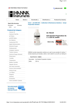
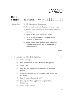
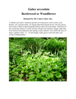
22 April 2015 McCloy Group Suite 1, Level 3, 426 King Street NEWCASTLE WEST NSW 2300 Attention: James Goode Dear James RE: PROPOSED SUBDIVISION – AQUILO ESTATE STAGE 6 STATION STREET, BONNELLS BAY LOT REGRADE & SITE CLASSIFICATION 1.0 Introduction Qualtest Laboratory NSW Pty Ltd (Qualtest) has carried out site regrade work with respect to the Level 1 Controlled Fill requirements of Australian Standard AS3798-2007, ‘Guidelines on Earthworks for Commercial and Residential Developments’ for the above mentioned site. The report also provides revised Site Classification to AS2870-2011, “Residential Slabs and Footings”, for the proposed subdivision following completion of site regrade works. Field work was carried out on 25 March 2015 and included the excavation of 14 test pits within Stages 5B, 6 & 8 of Aquilo Estate at Bonnells Bay. This report covers geotechnical investigations for Stage 6 (lots 601 to 618). Reference should be made to Qualtest Report Ref. NEW15P-0007A-AB for Lot Regrade and Site Classification for Stages 5B and 8. Figure AA1 attached shows the approximate test pit locations of TP1 to TP6 excavated within Stage 6, as well as lot numbers with reference to the site classifications provided in this report. Engineering Logs of TP1 to TP6 are attached. Reduced levels (AHD) shown on the logs are approximate only, based on interpolation to the nearest 0.5m from plans of the proposed subdivision provided by the client. 2.0 Site Regrading Works It is understood that where site regrading works were performed on lots 601 to 608 and lots 611 to 618, the regrading was limited to cutting and / or placement of topsoil and mulch to depths of less than 0.40m. During the field work investigations conducted on 25 March 2015, fill was observed on lots 609 and 610, with fill encountered to a depth of up to 0.9m in test pit TP6. This fill was assessed to be associated with previously stockpiled material placed on site. On 15 April 2015 a Principal Geotechnician from Qualtest witnessed the removal of fill from lots 609 and 610 as part of site regarding activities, which resulted in the remaining depth of fill being less than 0.40m. Qualtest Laboratory (NSW) Pty Ltd ABN: 98 153 268 896 8 Ironbark Close Warabrook NSW 2304 T: (02) 4968 4468 F: (02)4960 9775 W: www.qualtest.com.au NEW15P-0007A-AA PROPOSED SUBDIVISION – AQUILO STAGE 6 3.0 Laboratory Testing Samples collected during the field investigations were returned to our NATA Accredited Warabrook Laboratory for testing which comprised of six shrink/swell tests and one Atterberg Limits test on the samples recovered from Stage 6. Results of the shrink/swell and Atterberg Limits testing are attached, with a summary of the results provided in Tables 1 and 2. TABLE 1 – SUMMARY OF SHRINK / SWELL TESTING RESULTS Location Depth (m) Material Description Iss (%) TP1 0.60 – 0.90 (CH) CLAY 0.5 TP1 1.00 – 1.30 (CH) Sandy CLAY 1.6 TP3 0.50 – 0.90 (CL) Sandy CLAY 1.3 TP5 0.50 – 0.90 (CL) Sandy CLAY 3.4 TP6 0.60 – 0.90 FILL - (CH) CLAY 2.1 TP6 1.10 – 1.40 (CH) Sandy CLAY 3.0 TABLE 2 – SUMMARY OF ATTERBERG LIMITS TESTING RESULTS Location Depth (m) Material Description Liquid Limit (%) Plasticity Index (%) Linear Shrinkage (%) TP3 0.90 – 1.30 (CL) Sandy CLAY 40 22 7.0 4.0 Site Classification to AS2870-2011 Based on the results of the fieldwork, laboratory testing, previous experience in the area, and site regrading works carried out, residential lots located within the proposed subdivision of Aquilo Estates Stage 6 located at Station Street Bonnells Bay, as shown in Figure AA1, are classified in their current condition in accordance with the classification system presented in AS2870-2011 ’Residential Slabs and Footings’, as shown in Table 3. TABLE 3 – SITE CLASSIFICATION TO AS2870-2011 22 April 2015 Lot Numbers Site Classification 601 to 608 and 611 to 618 M 609 and 610 H1 2 NEW15P-0007A-AA PROPOSED SUBDIVISION – AQUILO STAGE 6 A characteristic free surface movement of 20mm to 40mm is estimated for areas classified as Class ‘M’ in their existing condition. A characteristic free surface movement of 40mm to 60mm is estimated for areas classified as Class ‘H1’ in their existing condition. The effects of changes to the soil profile by additional cutting and filling and the effects of past and future trees should be considered in selection of the design value for differential movement. If site re-grading works involving cutting or filling are performed after the date of this assessment, the classification may change and further advice should be sought. Footings for the proposed development should be designed and constructed in accordance with the requirements of AS2870-2011. The classification presented above assumes that: All footings are founded in controlled fill (if applicable) or in the residual clayey soils or rock below all non-controlled fill, topsoil material and root zones, and fill under slab panels meets the requirements of AS2870-2011, in particular, the root zone must be removed prior to the placement of fill materials beneath slabs; The performance expectations set out in Appendix B of AS2870-2011 are acceptable, and that site foundation maintenance is undertaken to avoid extremes of wetting and drying; Footings are to be founded outside of or below all zones of influence resulting from existing or future service trenches; The constructional and architectural requirements for reactive clay sites set out in AS28702011 are followed; Adherence to the detailing requirement outlined in Section 5 of AS2870-2011 ‘Residential Slabs and Footings’ is essential, in particular Section 5.6, ‘Additional requirements for Classes M, H1, H2 and E sites’ including architectural restrictions, plumbing and drainage requirements. Site maintenance complies with the provisions of CSIRO Sheet BTF 18, “Foundation Maintenance and Footing Performance: A Homeowner’s Guide”, a copy of which is attached in Appendix C. All structural elements on all lots should be supported on footings founded beneath all uncontrolled fill, layers of inadequate bearing capacity, soft/loose, wet or other potentially deleterious material. If any areas of uncontrolled fill of depths greater than 0.4m are encountered during construction, they should be designed in accordance with engineering principles for Class ‘P’ sites. 5.0 Limitations The findings presented in the report and used as the basis for recommendations presented herein were obtained using normal, industry accepted geotechnical design practices and standards. To our knowledge, they represent a reasonable interpretation of the general conditions of the site. 22 April 2015 3 NEW15P-0007A-AA PROPOSED SUBDIVISION – AQUILO STAGE 6 The extent of testing associated with this assessment is limited to discrete test locations. It should be noted that subsurface conditions between and away from the test locations may be different to those observed during the field work and used as the basis of the recommendations contained in this report. If subsurface conditions encountered during construction differ from those given in this report, further advice should be sought without delay. Data and opinions contained within the report may not be used in other contexts or for any other purposes without prior review and agreement by Qualtest. If this report is reproduced, it must be in full. If you have any further questions regarding this report, please do not hesitate to contact Alan Cullen or the undersigned. For and on behalf of Qualtest Laboratory (NSW) Pty Ltd Jason Lee Principal Geotechnical Engineer Attachments: Figure AA1 – Approximate Test Location Plan Results of Field Investigations Results of Laboratory Testing CSIRO Sheet BTF 18 - Foundation Maintenance and Footing Performance 22 April 2015 4 NEW15P-0007A-AA TP5 TP6 TP4 TP3 TP2 TP1 LEGEND: Approximate test pit location. Figure based on proposed subdivision plan provided by McCloy Group (Ref. Project No: 14149C, Drawing No: C02, Revision 2, dated 20/08/2014), by GCA. Client: MCCLOY GROUP Drawing No: FIGURE AA1 Project: PROPOSED SUBDIVISION - AQUILO ESTATE - STAGE 6 Project No: NEW15P-0007A Location: STATION STREET, BONNELLS BAY Scale: AS SHOWN Title: APPROXIMATE TEST LOCATION PLAN Date: 21 April 2015 TEST PIT NO: CLIENT: PAGE: 1 OF 1 JOB NO: NEW15P-0007A LOGGED BY: AAC DATE: 25/3/15 MCCLOY GROUP PROJECT: AQUILO ESTATE - STAGE 6 LOCATION: BONNELLS BAY SM 0.10m Silty SAND - fine to coarse grained, dark grey, with fines of low plasticity. Sandy CLAY - medium plasticity, pale orange, brown, fine to coarse grained. CL D TOPSOIL RESIDUAL SOIL 0.5 0.60m 0.60m VSt CLAY - high plasticity, pale grey, with trace of ironstone staining. U50 CH 0.90m 1.00m M > wP Not Encountered E 29.0 M Structure and additional observations Result MATERIAL DESCRIPTION: Soil type, plasticity/particle characteristics,colour,minor components CONSISTENCY DENSITY DEPTH (m) Field Test M > wP RL (m) CLASSIFICATION SYMBOL SAMPLES 29.5 m AHD Material description and profile information GRAPHIC LOG WATER METHOD Drilling and Sampling SURFACE RL: DATUM: Test Type Komatsu PC130 Excavator 0.5 m WIDTH: 1.5 m MOISTURE CONDITION EQUIPMENT TYPE: TEST PIT LENGTH: TP01 ENGINEERING LOG - TEST PIT 28.5 1.0 1.10m M < wP 1.30m 28.0 QT LIB 1.1.GLB Log NON-CORED BOREHOLE - TEST PIT NEW15P-0007A.GPJ <<DrawingFile>> 21/04/2015 13:35 8.30.003 Datgel Lab and In Situ Tool EXTREMELY TO HIGHLY WEATHERED ROCK SANDSTONE - pale white, fine to medium grained. U50 1.5 H 1.50m Hole Terminated at 1.50 m Effective Excavation Refusal 27.5 2.0 27.0 2.5 LEGEND: Water Water Level (Date and time shown) Water Inflow Water Outflow Strata Changes Gradational or transitional strata Definitive or distict strata change Notes, Samples and Tests U50 50mm Diameter tube sample CBR Bulk sample for CBR testing E Environmental sample (Glass jar, sealed and chilled on site) ASS Acid Sulfate Soil Sample (Plastic bag, air expelled, chilled) B Bulk Sample Field Tests PID Photoionisation detector reading (ppm) DCP(x-y) Dynamic penetrometer test (test depth interval shown) HP Hand Penetrometer test (UCS kPa) Consistency VS Very Soft S Soft F Firm St Stiff VSt Very Stiff H Hard Fb Friable Density V L MD D VD UCS (kPa) <25 25 - 50 50 - 100 100 - 200 200 - 400 >400 Very Loose Loose Medium Dense Dense Very Dense Moisture Condition D Dry M Moist W Wet Wp Plastic Limit WL Liquid Limit Density Index <15% Density Index 15 - 35% Density Index 35 - 65% Density Index 65 - 85% Density Index 85 - 100% TEST PIT NO: CLIENT: PAGE: 1 OF 1 JOB NO: NEW15P-0007A LOGGED BY: AAC DATE: 25/3/15 MCCLOY GROUP PROJECT: AQUILO ESTATE - STAGE 6 LOCATION: BONNELLS BAY MATERIAL DESCRIPTION: Soil type, plasticity/particle characteristics,colour,minor components Mulch L Silty SAND - fine to medium grained, dark grey, with fines of low plasticity. D Not Encountered E 0.10m SM Structure and additional observations Result DEPTH (m) Field Test CONSISTENCY DENSITY RL (m) CLASSIFICATION SYMBOL SAMPLES 33.0 m AHD Material description and profile information GRAPHIC LOG WATER METHOD Drilling and Sampling SURFACE RL: DATUM: Test Type Komatsu PC130 Excavator 0.5 m WIDTH: 1.5 m MOISTURE CONDITION EQUIPMENT TYPE: TEST PIT LENGTH: TP02 ENGINEERING LOG - TEST PIT MULCH TOPSOIL 0.30m EXTREMELY TO HIGHLY WEATHERED ROCK SANDSTONE - fine to medium grained gravel, pale white, brown. 32.5 M 0.5 H 0.80m QT LIB 1.1.GLB Log NON-CORED BOREHOLE - TEST PIT NEW15P-0007A.GPJ <<DrawingFile>> 21/04/2015 13:36 8.30.003 Datgel Lab and In Situ Tool Hole Terminated at 0.80 m Excavator Refusal 32.0 1.0 31.5 1.5 31.0 2.0 30.5 2.5 LEGEND: Water Water Level (Date and time shown) Water Inflow Water Outflow Strata Changes Gradational or transitional strata Definitive or distict strata change Notes, Samples and Tests U50 50mm Diameter tube sample CBR Bulk sample for CBR testing E Environmental sample (Glass jar, sealed and chilled on site) ASS Acid Sulfate Soil Sample (Plastic bag, air expelled, chilled) B Bulk Sample Field Tests PID Photoionisation detector reading (ppm) DCP(x-y) Dynamic penetrometer test (test depth interval shown) HP Hand Penetrometer test (UCS kPa) Consistency VS Very Soft S Soft F Firm St Stiff VSt Very Stiff H Hard Fb Friable Density V L MD D VD UCS (kPa) <25 25 - 50 50 - 100 100 - 200 200 - 400 >400 Very Loose Loose Medium Dense Dense Very Dense Moisture Condition D Dry M Moist W Wet Wp Plastic Limit WL Liquid Limit Density Index <15% Density Index 15 - 35% Density Index 35 - 65% Density Index 65 - 85% Density Index 85 - 100% TEST PIT NO: CLIENT: PAGE: 1 OF 1 JOB NO: NEW15P-0007A LOGGED BY: AAC DATE: 25/3/15 MCCLOY GROUP PROJECT: AQUILO ESTATE - STAGE 6 LOCATION: BONNELLS BAY SM Not Encountered E 0.50m 29.0 0.10m Silty SAND - fine to medium grained, dark grey, little to no fines. Sandy CLAY - medium plasticity, pale orange, brown, with fine to coarse grained sand. M D Structure and additional observations Result MATERIAL DESCRIPTION: Soil type, plasticity/particle characteristics,colour,minor components CONSISTENCY DENSITY DEPTH (m) Field Test MOISTURE CONDITION RL (m) CLASSIFICATION SYMBOL SAMPLES 29.5 m AHD Material description and profile information GRAPHIC LOG WATER METHOD Drilling and Sampling SURFACE RL: DATUM: Test Type CAT 304CR Backhoe 0.4 m WIDTH: 1.5 m TOPSOIL RESIDUAL SOIL 0.5 U50 Grey to mottled red, grey, Sandy Clay with ironstone staining. CL 0.80m M > wP EQUIPMENT TYPE: TEST PIT LENGTH: TP03 ENGINEERING LOG - TEST PIT VSt 0.90m 28.5 1.0 U50 1.30m 1.30m EXTREMELY WEATHERED ROCK QT LIB 1.1.GLB Log NON-CORED BOREHOLE - TEST PIT NEW15P-0007A.GPJ <<DrawingFile>> 21/04/2015 13:36 8.30.003 Datgel Lab and In Situ Tool 28.0 M < wP SANDSTONE - fine to medium grained, pale white / grey. 1.5 H 1.70m Hole Terminated at 1.70 m Excavator Refusal 27.5 2.0 27.0 2.5 LEGEND: Water Water Level (Date and time shown) Water Inflow Water Outflow Strata Changes Gradational or transitional strata Definitive or distict strata change Notes, Samples and Tests U50 50mm Diameter tube sample CBR Bulk sample for CBR testing E Environmental sample (Glass jar, sealed and chilled on site) ASS Acid Sulfate Soil Sample (Plastic bag, air expelled, chilled) B Bulk Sample Field Tests PID Photoionisation detector reading (ppm) DCP(x-y) Dynamic penetrometer test (test depth interval shown) HP Hand Penetrometer test (UCS kPa) Consistency VS Very Soft S Soft F Firm St Stiff VSt Very Stiff H Hard Fb Friable Density V L MD D VD UCS (kPa) <25 25 - 50 50 - 100 100 - 200 200 - 400 >400 Very Loose Loose Medium Dense Dense Very Dense Moisture Condition D Dry M Moist W Wet Wp Plastic Limit WL Liquid Limit Density Index <15% Density Index 15 - 35% Density Index 35 - 65% Density Index 65 - 85% Density Index 85 - 100% TEST PIT NO: CLIENT: PAGE: 1 OF 1 JOB NO: NEW15P-0007A LOGGED BY: AAC DATE: 25/3/15 MCCLOY GROUP PROJECT: AQUILO ESTATE - STAGE 6 LOCATION: BONNELLS BAY MATERIAL DESCRIPTION: Soil type, plasticity/particle characteristics,colour,minor components Mulch L Silty SAND - fine to medium grained, dark grey, with fines of low plasticity. D Not Encountered E 0.10m SM Structure and additional observations Result DEPTH (m) Field Test CONSISTENCY DENSITY RL (m) CLASSIFICATION SYMBOL SAMPLES 33.0 m AHD Material description and profile information GRAPHIC LOG WATER METHOD Drilling and Sampling SURFACE RL: DATUM: Test Type Komatsu PC130 Excavator 0.5 m WIDTH: 1.5 m MOISTURE CONDITION EQUIPMENT TYPE: TEST PIT LENGTH: TP04 ENGINEERING LOG - TEST PIT MULCH TOPSOIL 0.30m EXTREMELY TO HIGHLY WEATHERED ROCK SANDSTONE - fine to medium grained gravel, pale white, brown. 32.5 M 0.5 H 0.80m QT LIB 1.1.GLB Log NON-CORED BOREHOLE - TEST PIT NEW15P-0007A.GPJ <<DrawingFile>> 21/04/2015 13:36 8.30.003 Datgel Lab and In Situ Tool Hole Terminated at 0.80 m Excavator Refusal 32.0 1.0 31.5 1.5 31.0 2.0 30.5 2.5 LEGEND: Water Water Level (Date and time shown) Water Inflow Water Outflow Strata Changes Gradational or transitional strata Definitive or distict strata change Notes, Samples and Tests U50 50mm Diameter tube sample CBR Bulk sample for CBR testing E Environmental sample (Glass jar, sealed and chilled on site) ASS Acid Sulfate Soil Sample (Plastic bag, air expelled, chilled) B Bulk Sample Field Tests PID Photoionisation detector reading (ppm) DCP(x-y) Dynamic penetrometer test (test depth interval shown) HP Hand Penetrometer test (UCS kPa) Consistency VS Very Soft S Soft F Firm St Stiff VSt Very Stiff H Hard Fb Friable Density V L MD D VD UCS (kPa) <25 25 - 50 50 - 100 100 - 200 200 - 400 >400 Very Loose Loose Medium Dense Dense Very Dense Moisture Condition D Dry M Moist W Wet Wp Plastic Limit WL Liquid Limit Density Index <15% Density Index 15 - 35% Density Index 35 - 65% Density Index 65 - 85% Density Index 85 - 100% TEST PIT NO: CLIENT: PAGE: 1 OF 1 JOB NO: NEW15P-0007A LOGGED BY: AAC DATE: 25/3/15 MCCLOY GROUP PROJECT: AQUILO ESTATE - STAGE 6 LOCATION: BONNELLS BAY MATERIAL DESCRIPTION: Soil type, plasticity/particle characteristics,colour,minor components TOPSOIL / FILL - TRACE OF CHITTER Clayey SAND - fine to coarse grained, dark grey, fines of low plasticity. SC M 0.20m SM Structure and additional observations Result DEPTH (m) Field Test CONSISTENCY DENSITY RL (m) CLASSIFICATION SYMBOL SAMPLES 30.0 m AHD Material description and profile information GRAPHIC LOG WATER METHOD Drilling and Sampling SURFACE RL: DATUM: Test Type Komatsu PC130 Excavator 0.5 m WIDTH: 1.5 m MOISTURE CONDITION EQUIPMENT TYPE: TEST PIT LENGTH: TP05 ENGINEERING LOG - TEST PIT MD Silty SAND - fine to medium grained, pale grey, low plasticity. COLLUVIUM Sandy CLAY - medium plasticity, pale brown, orange. RESIDUAL SOIL 0.50m 29.5 0.5 U50 M > wP Not Encountered E 0.35m CL VSt 0.90m 29.0 1.0 Grading red, pale white. 1.10m CLAY - high plasticity, pale grey. 1.20m SANDSTONE - pale white. H/F M < wP CH EXTREMELY WEATHERED ROCK H QT LIB 1.1.GLB Log NON-CORED BOREHOLE - TEST PIT NEW15P-0007A.GPJ <<DrawingFile>> 21/04/2015 13:36 8.30.003 Datgel Lab and In Situ Tool 1.40m 28.5 1.5 28.0 2.0 27.5 2.5 LEGEND: Water Water Level (Date and time shown) Water Inflow Water Outflow Strata Changes Gradational or transitional strata Definitive or distict strata change Hole Terminated at 1.40 m Effective Refusal Notes, Samples and Tests U50 50mm Diameter tube sample CBR Bulk sample for CBR testing E Environmental sample (Glass jar, sealed and chilled on site) ASS Acid Sulfate Soil Sample (Plastic bag, air expelled, chilled) B Bulk Sample Field Tests PID Photoionisation detector reading (ppm) DCP(x-y) Dynamic penetrometer test (test depth interval shown) HP Hand Penetrometer test (UCS kPa) Consistency VS Very Soft S Soft F Firm St Stiff VSt Very Stiff H Hard Fb Friable Density V L MD D VD UCS (kPa) <25 25 - 50 50 - 100 100 - 200 200 - 400 >400 Very Loose Loose Medium Dense Dense Very Dense Moisture Condition D Dry M Moist W Wet Wp Plastic Limit WL Liquid Limit Density Index <15% Density Index 15 - 35% Density Index 35 - 65% Density Index 65 - 85% Density Index 85 - 100% TEST PIT NO: CLIENT: PAGE: 1 OF 1 JOB NO: NEW15P-0007A LOGGED BY: AAC DATE: 25/3/15 MCCLOY GROUP PROJECT: AQUILO ESTATE - STAGE 6 LOCATION: BONNELLS BAY SM MATERIAL DESCRIPTION: Soil type, plasticity/particle characteristics,colour,minor components 0.10m Silty SAND - fine to medium grained, dark grey, fines of low plasticity. CLAY - high plasticity, grey and brown, fine to coarse grained sand. W MD Structure and additional observations Result DEPTH (m) Field Test CONSISTENCY DENSITY RL (m) CLASSIFICATION SYMBOL SAMPLES 29.5 m AHD Material description and profile information GRAPHIC LOG WATER METHOD Drilling and Sampling SURFACE RL: DATUM: Test Type Komatsu PC130 Excavator 0.5 m WIDTH: 1.5 m MOISTURE CONDITION EQUIPMENT TYPE: TEST PIT LENGTH: TP06 ENGINEERING LOG - TEST PIT TOPSOIL FILL 29.0 0.5 M > wP St CH 0.60m Not Encountered E U50 0.90m 0.90m 28.5 1.0 28.0 1.5 RESIDUAL SOIL Sandy CLAY - medium to high plasticity, pale grey and brown, grey to mottled grey brown, becoming friable with depth. VSt 1.10m U50 QT LIB 1.1.GLB Log NON-CORED BOREHOLE - TEST PIT NEW15P-0007A.GPJ <<DrawingFile>> 21/04/2015 13:36 8.30.003 Datgel Lab and In Situ Tool M < wP 1.40m CH VSt / H 27.5 2.0 2.00m Hole Terminated at 2.00 m 27.0 LEGEND: Water Water Level (Date and time shown) Water Inflow Water Outflow Strata Changes Gradational or transitional strata Definitive or distict strata change 2.5 Notes, Samples and Tests U50 50mm Diameter tube sample CBR Bulk sample for CBR testing E Environmental sample (Glass jar, sealed and chilled on site) ASS Acid Sulfate Soil Sample (Plastic bag, air expelled, chilled) B Bulk Sample Field Tests PID Photoionisation detector reading (ppm) DCP(x-y) Dynamic penetrometer test (test depth interval shown) HP Hand Penetrometer test (UCS kPa) Consistency VS Very Soft S Soft F Firm St Stiff VSt Very Stiff H Hard Fb Friable Density V L MD D VD UCS (kPa) <25 25 - 50 50 - 100 100 - 200 200 - 400 >400 Very Loose Loose Medium Dense Dense Very Dense Moisture Condition D Dry M Moist W Wet Wp Plastic Limit WL Liquid Limit Density Index <15% Density Index 15 - 35% Density Index 35 - 65% Density Index 65 - 85% Density Index 85 - 100% QUALTEST Laboratory (NSW) Pty Ltd 8 Ironbark Close Warabrook NSW 2304 T: 02 4968 4468 F: 02 4960 9775 E: [email protected] W: www.qualtest.com.au ABN: 98 153 268 896 Report No: SSI:NEW15W-0702--S01 Issue No: 1 Shrink Swell Index Report Client: Accredited for compliance with ISO/IEC 17025 The results of the tests, calibrations and/or measurements included in this document are traceable to Australian/national standards McCloys Bonnells Bay PTY LTD c/o McCloy Group PO Box 2214, Dangar NSW 2309 Principal: NEW15P-0007A Project No.: Project Name: Aquilo Estate - Stages 6 and 5B & 8 Approved Signatory: Alan Cullen (Principal Geotechnician) NATA Accredited Laboratory Number18686 Date of Issue: 2/04/2015 Sample Details Sample ID: Test Request No.: Material: Source: Specification: Project Location: Sample Location: Borehole Number: Borehole Depth (m): NEW15W-0702--S01 Client Sample ID: Sampling Method: Date Sampled: Date Submitted: Sandy Clay On - Site AS1289.1.2.1 cl 6.5.4 25/03/2015 26/03/2015 No Specification Bonnells Bay, NSW TP1 - (0.6 - 0.9m) TP1 0.6 to 0.9m Swell Test Swell on Saturation (%): Moisture Content before (%): Moisture Content after (%): Est. Unc. Comp. Strength before (kPa): Est. Unc. Comp. Strength after (kPa): AS 1289.7.1.1 Shrink Test -0.9 11.7 14.8 >600 >600 Shrink on drying (%): Shrinkage Moisture Content (%): Est. inert material (%): Crumbling during shrinkage: Cracking during shrinkage: AS 1289.7.1.1 0.8 12.1 0 Nil Nil Shrink Swell Shrink Swell Index - Iss (%): 0.5 Comments Form No: 18932, Report No: SSI:NEW15W-0702--S01 © 2000-2013 QESTLab by SpectraQEST.com Page 1 of 1 QUALTEST Laboratory (NSW) Pty Ltd 8 Ironbark Close Warabrook NSW 2304 T: 02 4968 4468 F: 02 4960 9775 E: [email protected] W: www.qualtest.com.au ABN: 98 153 268 896 Report No: SSI:NEW15W-0702--S02 Issue No: 1 Shrink Swell Index Report Client: Accredited for compliance with ISO/IEC 17025 The results of the tests, calibrations and/or measurements included in this document are traceable to Australian/national standards McCloys Bonnells Bay PTY LTD c/o McCloy Group PO Box 2214, Dangar NSW 2309 Principal: NEW15P-0007A Project No.: Project Name: Aquilo Estate - Stages 6 and 5B & 8 Approved Signatory: Alan Cullen (Principal Geotechnician) NATA Accredited Laboratory Number18686 Date of Issue: 2/04/2015 Sample Details Sample ID: Test Request No.: Material: Source: Specification: Project Location: Sample Location: Borehole Number: Borehole Depth (m): NEW15W-0702--S02 Client Sample ID: Sampling Method: Date Sampled: Date Submitted: Sandy Clay On - Site AS1289.1.2.1 cl 6.5.4 25/03/2015 26/03/2015 No Specification Bonnells Bay, NSW TP1 - (1.0 - 1.3m) TP1 1.0 to 1.3m Swell Test Swell on Saturation (%): Moisture Content before (%): Moisture Content after (%): Est. Unc. Comp. Strength before (kPa): Est. Unc. Comp. Strength after (kPa): AS 1289.7.1.1 Shrink Test -0.7 18.6 23.8 450 500 Shrink on drying (%): Shrinkage Moisture Content (%): Est. inert material (%): Crumbling during shrinkage: Cracking during shrinkage: AS 1289.7.1.1 2.8 18.6 0 Nil Moderate Shrink Swell Shrink Swell Index - Iss (%): 1.6 Comments Form No: 18932, Report No: SSI:NEW15W-0702--S02 © 2000-2013 QESTLab by SpectraQEST.com Page 1 of 1 QUALTEST Laboratory (NSW) Pty Ltd 8 Ironbark Close Warabrook NSW 2304 T: 02 4968 4468 F: 02 4960 9775 E: [email protected] W: www.qualtest.com.au ABN: 98 153 268 896 Report No: SSI:NEW15W-0702--S03 Issue No: 1 Shrink Swell Index Report Client: Accredited for compliance with ISO/IEC 17025 The results of the tests, calibrations and/or measurements included in this document are traceable to Australian/national standards McCloys Bonnells Bay PTY LTD c/o McCloy Group PO Box 2214, Dangar NSW 2309 Principal: NEW15P-0007A Project No.: Project Name: Aquilo Estate - Stages 6 and 5B & 8 Approved Signatory: Alan Cullen (Principal Geotechnician) NATA Accredited Laboratory Number18686 Date of Issue: 2/04/2015 Sample Details Sample ID: Test Request No.: Material: Source: Specification: Project Location: Sample Location: Borehole Number: Borehole Depth (m): NEW15W-0702--S03 Client Sample ID: Sampling Method: Date Sampled: Date Submitted: Sandy Clay On - Site AS1289.1.2.1 cl 6.5.4 25/03/2015 26/03/2015 No Specification Bonnells Bay, NSW TP3 - (0.5 - 0.9m) TP3 0.5 to 0.9m Swell Test Swell on Saturation (%): Moisture Content before (%): Moisture Content after (%): Est. Unc. Comp. Strength before (kPa): Est. Unc. Comp. Strength after (kPa): AS 1289.7.1.1 Shrink Test -0.4 22.5 27.5 550 550 Shrink on drying (%): Shrinkage Moisture Content (%): Est. inert material (%): Crumbling during shrinkage: Cracking during shrinkage: AS 1289.7.1.1 2.4 22.0 0 Nil Major Shrink Swell Shrink Swell Index - Iss (%): 1.3 Comments Form No: 18932, Report No: SSI:NEW15W-0702--S03 © 2000-2013 QESTLab by SpectraQEST.com Page 1 of 1 QUALTEST Laboratory (NSW) Pty Ltd 8 Ironbark Close Warabrook NSW 2304 T: 02 4968 4468 F: 02 4960 9775 E: [email protected] W: www.qualtest.com.au ABN: 98 153 268 896 Report No: SSI:NEW15W-0702--S05 Issue No: 1 Shrink Swell Index Report Client: Accredited for compliance with ISO/IEC 17025 The results of the tests, calibrations and/or measurements included in this document are traceable to Australian/national standards McCloys Bonnells Bay PTY LTD c/o McCloy Group PO Box 2214, Dangar NSW 2309 Principal: NEW15P-0007A Project No.: Project Name: Aquilo Estate - Stages 6 and 5B & 8 Approved Signatory: Alan Cullen (Principal Geotechnician) NATA Accredited Laboratory Number18686 Date of Issue: 2/04/2015 Sample Details Sample ID: Test Request No.: Material: Source: Specification: Project Location: Sample Location: Borehole Number: Borehole Depth (m): NEW15W-0702--S05 Client Sample ID: Sampling Method: Date Sampled: Date Submitted: Sandy Clay On - Site AS1289.1.2.1 cl 6.5.4 25/03/2015 26/03/2015 No Specification Bonnells Bay, NSW TP5 - (0.5 - 0.9m) TP5 0.5 to 0.9m Swell Test Swell on Saturation (%): Moisture Content before (%): Moisture Content after (%): Est. Unc. Comp. Strength before (kPa): Est. Unc. Comp. Strength after (kPa): AS 1289.7.1.1 Shrink Test -0.5 29.2 32.1 400 500 Shrink on drying (%): Shrinkage Moisture Content (%): Est. inert material (%): Crumbling during shrinkage: Cracking during shrinkage: AS 1289.7.1.1 6.1 30.3 0 Nil Major Shrink Swell Shrink Swell Index - Iss (%): 3.4 Comments Form No: 18932, Report No: SSI:NEW15W-0702--S05 © 2000-2013 QESTLab by SpectraQEST.com Page 1 of 1 QUALTEST Laboratory (NSW) Pty Ltd 8 Ironbark Close Warabrook NSW 2304 T: 02 4968 4468 F: 02 4960 9775 E: [email protected] W: www.qualtest.com.au ABN: 98 153 268 896 Report No: SSI:NEW15W-0702--S06 Issue No: 1 Shrink Swell Index Report Client: Accredited for compliance with ISO/IEC 17025 The results of the tests, calibrations and/or measurements included in this document are traceable to Australian/national standards McCloys Bonnells Bay PTY LTD c/o McCloy Group PO Box 2214, Dangar NSW 2309 Principal: NEW15P-0007A Project No.: Project Name: Aquilo Estate - Stages 6 and 5B & 8 Approved Signatory: Alan Cullen (Principal Geotechnician) NATA Accredited Laboratory Number18686 Date of Issue: 2/04/2015 Sample Details Sample ID: Test Request No.: Material: Source: Specification: Project Location: Sample Location: Borehole Number: Borehole Depth (m): NEW15W-0702--S06 Client Sample ID: Sampling Method: Date Sampled: Date Submitted: Sandy Clay On - Site AS1289.1.2.1 cl 6.5.4 25/03/2015 26/03/2015 No Specification Bonnells Bay, NSW TP6 - (0.6 - 0.9m) TP6 0.6 to 0.9m Swell Test Swell on Saturation (%): Moisture Content before (%): Moisture Content after (%): Est. Unc. Comp. Strength before (kPa): Est. Unc. Comp. Strength after (kPa): AS 1289.7.1.1 Shrink Test -2.2 22.3 23.3 450 500 Shrink on drying (%): Shrinkage Moisture Content (%): Est. inert material (%): Crumbling during shrinkage: Cracking during shrinkage: AS 1289.7.1.1 3.8 23.1 0 Nil Major Shrink Swell Shrink Swell Index - Iss (%): 2.1 Comments Form No: 18932, Report No: SSI:NEW15W-0702--S06 © 2000-2013 QESTLab by SpectraQEST.com Page 1 of 1 QUALTEST Laboratory (NSW) Pty Ltd 8 Ironbark Close Warabrook NSW 2304 T: 02 4968 4468 F: 02 4960 9775 E: [email protected] W: www.qualtest.com.au ABN: 98 153 268 896 Report No: SSI:NEW15W-0702--S07 Issue No: 1 Shrink Swell Index Report Client: Accredited for compliance with ISO/IEC 17025 The results of the tests, calibrations and/or measurements included in this document are traceable to Australian/national standards McCloys Bonnells Bay PTY LTD c/o McCloy Group PO Box 2214, Dangar NSW 2309 Principal: NEW15P-0007A Project No.: Project Name: Aquilo Estate - Stages 6 and 5B & 8 Approved Signatory: Alan Cullen (Principal Geotechnician) NATA Accredited Laboratory Number18686 Date of Issue: 2/04/2015 Sample Details Sample ID: Test Request No.: Material: Source: Specification: Project Location: Sample Location: Borehole Number: Borehole Depth (m): NEW15W-0702--S07 Client Sample ID: Sampling Method: Date Sampled: Date Submitted: Sandy Clay On - Site AS1289.1.2.1 cl 6.5.4 25/03/2015 26/03/2015 No Specification Bonnells Bay, NSW TP6 - (1.1 - 1.4m) TP6 1.1 to 1.4m Swell Test Swell on Saturation (%): Moisture Content before (%): Moisture Content after (%): Est. Unc. Comp. Strength before (kPa): Est. Unc. Comp. Strength after (kPa): AS 1289.7.1.1 Shrink Test -0.4 27.1 28.9 >600 250 Shrink on drying (%): Shrinkage Moisture Content (%): Est. inert material (%): Crumbling during shrinkage: Cracking during shrinkage: AS 1289.7.1.1 5.4 26.6 0 Nil Minor Shrink Swell Shrink Swell Index - Iss (%): 3.0 Comments Form No: 18932, Report No: SSI:NEW15W-0702--S07 © 2000-2013 QESTLab by SpectraQEST.com Page 1 of 1 QUALTEST Laboratory (NSW) Pty Ltd 8 Ironbark Close Warabrook NSW 2304 T: 02 4968 4468 F: 02 4960 9775 E: [email protected] W: www.qualtest.com.au ABN: 98 153 268 896 Report No: MAT:NEW15W-0702--S04 Issue No: 1 Material Test Report Client: Accredited for compliance with ISO/IEC 17025 The results of the tests, calibrations and/or measurements included in this document are traceable to Australian/national standards McCloys Bonnells Bay PTY LTD c/o McCloy Group PO Box 2214, Dangar NSW 2309 Principal: NEW15P-0007A Project No.: Project Name: Aquilo Estate - Stages 6 and 5B & 8 Approved Signatory: Alan Cullen (Principal Geotechnician) NATA Accredited Laboratory Number18686 Date of Issue: 2/04/2015 Sample Details Sample ID: Sampling Method: Date Sampled: Source: Material: Specification: Project Location: Sample Location: Particle Size Distribution NEW15W-0702--S04 AS1289.1.2.1 cl 6.5.4 25/03/2015 On - Site Sandy Clay No Specification Bonnells Bay, NSW TP3 - (0.9 - 1.3m) Other Test Results Description Sample History Preparation Linear Shrinkage (%) Mould Length (mm) Crumbling Curling Cracking Liquid Limit (%) Method Plastic Limit (%) Plasticity Index (%) Method Result AS 1289.1.1 Air-dried AS 1289.1.1 Dry Sieved AS 1289.3.4.1 7.0 250 No No Yes AS 1289.3.1.1 40 Four Point AS 1289.3.2.1 18 AS 1289.3.3.1 22 Limits Chart Comments N/A Form No: 18909, Report No: MAT:NEW15W-0702--S04 © 2000-2013 QESTLab by SpectraQEST.com Page 1 of 1 Foundation Maintenance and Footing Performance: A Homeowner’s Guide BTF 18 replaces Information Sheet 10/91 Buildings can and often do move. This movement can be up, down, lateral or rotational. The fundamental cause of movement in buildings can usually be related to one or more problems in the foundation soil. It is important for the homeowner to identify the soil type in order to ascertain the measures that should be put in place in order to ensure that problems in the foundation soil can be prevented, thus protecting against building movement. This Building Technology File is designed to identify causes of soil-related building movement, and to suggest methods of prevention of resultant cracking in buildings. Soil Types The types of soils usually present under the topsoil in land zoned for residential buildings can be split into two approximate groups – granular and clay. Quite often, foundation soil is a mixture of both types. The general problems associated with soils having granular content are usually caused by erosion. Clay soils are subject to saturation and swell/shrink problems. Classifications for a given area can generally be obtained by application to the local authority, but these are sometimes unreliable and if there is doubt, a geotechnical report should be commissioned. As most buildings suffering movement problems are founded on clay soils, there is an emphasis on classification of soils according to the amount of swell and shrinkage they experience with variations of water content. The table below is Table 2.1 from AS 2870, the Residential Slab and Footing Code. Causes of Movement Settlement due to construction There are two types of settlement that occur as a result of construction: • Immediate settlement occurs when a building is first placed on its foundation soil, as a result of compaction of the soil under the weight of the structure. The cohesive quality of clay soil mitigates against this, but granular (particularly sandy) soil is susceptible. • Consolidation settlement is a feature of clay soil and may take place because of the expulsion of moisture from the soil or because of the soil’s lack of resistance to local compressive or shear stresses. This will usually take place during the first few months after construction, but has been known to take many years in exceptional cases. These problems are the province of the builder and should be taken into consideration as part of the preparation of the site for construction. Building Technology File 19 (BTF 19) deals with these problems. Erosion All soils are prone to erosion, but sandy soil is particularly susceptible to being washed away. Even clay with a sand component of say 10% or more can suffer from erosion. Saturation This is particularly a problem in clay soils. Saturation creates a boglike suspension of the soil that causes it to lose virtually all of its bearing capacity. To a lesser degree, sand is affected by saturation because saturated sand may undergo a reduction in volume – particularly imported sand fill for bedding and blinding layers. However, this usually occurs as immediate settlement and should normally be the province of the builder. Seasonal swelling and shrinkage of soil All clays react to the presence of water by slowly absorbing it, making the soil increase in volume (see table below). The degree of increase varies considerably between different clays, as does the degree of decrease during the subsequent drying out caused by fair weather periods. Because of the low absorption and expulsion rate, this phenomenon will not usually be noticeable unless there are prolonged rainy or dry periods, usually of weeks or months, depending on the land and soil characteristics. The swelling of soil creates an upward force on the footings of the building, and shrinkage creates subsidence that takes away the support needed by the footing to retain equilibrium. Shear failure This phenomenon occurs when the foundation soil does not have sufficient strength to support the weight of the footing. There are two major post-construction causes: • Significant load increase. • Reduction of lateral support of the soil under the footing due to erosion or excavation. • In clay soil, shear failure can be caused by saturation of the soil adjacent to or under the footing. GENERAL DEFINITIONS OF SITE CLASSES Class Foundation A Most sand and rock sites with little or no ground movement from moisture changes S Slightly reactive clay sites with only slight ground movement from moisture changes M Moderately reactive clay or silt sites, which can experience moderate ground movement from moisture changes H Highly reactive clay sites, which can experience high ground movement from moisture changes E Extremely reactive sites, which can experience extreme ground movement from moisture changes A to P P Filled sites Sites which include soft soils, such as soft clay or silt or loose sands; landslip; mine subsidence; collapsing soils; soils subject to erosion; reactive sites subject to abnormal moisture conditions or sites which cannot be classified otherwise Tree root growth Trees and shrubs that are allowed to grow in the vicinity of footings can cause foundation soil movement in two ways: Trees can cause shrinkage and damage • Roots that grow under footings may increase in cross-sectional size, exerting upward pressure on footings. • Roots in the vicinity of footings will absorb much of the moisture in the foundation soil, causing shrinkage or subsidence. Unevenness of Movement The types of ground movement described above usually occur unevenly throughout the building’s foundation soil. Settlement due to construction tends to be uneven because of: • Differing compaction of foundation soil prior to construction. • Differing moisture content of foundation soil prior to construction. Movement due to non-construction causes is usually more uneven still. Erosion can undermine a footing that traverses the flow or can create the conditions for shear failure by eroding soil adjacent to a footing that runs in the same direction as the flow. Saturation of clay foundation soil may occur where subfloor walls create a dam that makes water pond. It can also occur wherever there is a source of water near footings in clay soil. This leads to a severe reduction in the strength of the soil which may create local shear failure. Seasonal swelling and shrinkage of clay soil affects the perimeter of the building first, then gradually spreads to the interior. The swelling process will usually begin at the uphill extreme of the building, or on the weather side where the land is flat. Swelling gradually reaches the interior soil as absorption continues. Shrinkage usually begins where the sun’s heat is greatest. Effects of Uneven Soil Movement on Structures Erosion and saturation Erosion removes the support from under footings, tending to create subsidence of the part of the structure under which it occurs. Brickwork walls will resist the stress created by this removal of support by bridging the gap or cantilevering until the bricks or the mortar bedding fail. Older masonry has little resistance. Evidence of failure varies according to circumstances and symptoms may include: • Step cracking in the mortar beds in the body of the wall or above/below openings such as doors or windows. • Vertical cracking in the bricks (usually but not necessarily in line with the vertical beds or perpends). Isolated piers affected by erosion or saturation of foundations will eventually lose contact with the bearers they support and may tilt or fall over. The floors that have lost this support will become bouncy, sometimes rattling ornaments etc. Seasonal swelling/shrinkage in clay Swelling foundation soil due to rainy periods first lifts the most exposed extremities of the footing system, then the remainder of the perimeter footings while gradually permeating inside the building footprint to lift internal footings. This swelling first tends to create a dish effect, because the external footings are pushed higher than the internal ones. The first noticeable symptom may be that the floor appears slightly dished. This is often accompanied by some doors binding on the floor or the door head, together with some cracking of cornice mitres. In buildings with timber flooring supported by bearers and joists, the floor can be bouncy. Externally there may be visible dishing of the hip or ridge lines. As the moisture absorption process completes its journey to the innermost areas of the building, the internal footings will rise. If the spread of moisture is roughly even, it may be that the symptoms will temporarily disappear, but it is more likely that swelling will be uneven, creating a difference rather than a disappearance in symptoms. In buildings with timber flooring supported by bearers and joists, the isolated piers will rise more easily than the strip footings or piers under walls, creating noticeable doming of flooring. As the weather pattern changes and the soil begins to dry out, the external footings will be first affected, beginning with the locations where the sun’s effect is strongest. This has the effect of lowering the external footings. The doming is accentuated and cracking reduces or disappears where it occurred because of dishing, but other cracks open up. The roof lines may become convex. Doming and dishing are also affected by weather in other ways. In areas where warm, wet summers and cooler dry winters prevail, water migration tends to be toward the interior and doming will be accentuated, whereas where summers are dry and winters are cold and wet, migration tends to be toward the exterior and the underlying propensity is toward dishing. Movement caused by tree roots In general, growing roots will exert an upward pressure on footings, whereas soil subject to drying because of tree or shrub roots will tend to remove support from under footings by inducing shrinkage. Complications caused by the structure itself Most forces that the soil causes to be exerted on structures are vertical – i.e. either up or down. However, because these forces are seldom spread evenly around the footings, and because the building resists uneven movement because of its rigidity, forces are exerted from one part of the building to another. The net result of all these forces is usually rotational. This resultant force often complicates the diagnosis because the visible symptoms do not simply reflect the original cause. A common symptom is binding of doors on the vertical member of the frame. Effects on full masonry structures Brickwork will resist cracking where it can. It will attempt to span areas that lose support because of subsided foundations or raised points. It is therefore usual to see cracking at weak points, such as openings for windows or doors. In the event of construction settlement, cracking will usually remain unchanged after the process of settlement has ceased. With local shear or erosion, cracking will usually continue to develop until the original cause has been remedied, or until the subsidence has completely neutralised the affected portion of footing and the structure has stabilised on other footings that remain effective. In the case of swell/shrink effects, the brickwork will in some cases return to its original position after completion of a cycle, however it is more likely that the rotational effect will not be exactly reversed, and it is also usual that brickwork will settle in its new position and will resist the forces trying to return it to its original position. This means that in a case where swelling takes place after construction and cracking occurs, the cracking is likely to at least partly remain after the shrink segment of the cycle is complete. Thus, each time the cycle is repeated, the likelihood is that the cracking will become wider until the sections of brickwork become virtually independent. With repeated cycles, once the cracking is established, if there is no other complication, it is normal for the incidence of cracking to stabilise, as the building has the articulation it needs to cope with the problem. This is by no means always the case, however, and monitoring of cracks in walls and floors should always be treated seriously. Upheaval caused by growth of tree roots under footings is not a simple vertical shear stress. There is a tendency for the root to also exert lateral forces that attempt to separate sections of brickwork after initial cracking has occurred. The normal structural arrangement is that the inner leaf of brickwork in the external walls and at least some of the internal walls (depending on the roof type) comprise the load-bearing structure on which any upper floors, ceilings and the roof are supported. In these cases, it is internally visible cracking that should be the main focus of attention, however there are a few examples of dwellings whose external leaf of masonry plays some supporting role, so this should be checked if there is any doubt. In any case, externally visible cracking is important as a guide to stresses on the structure generally, and it should also be remembered that the external walls must be capable of supporting themselves. Effects on framed structures Timber or steel framed buildings are less likely to exhibit cracking due to swell/shrink than masonry buildings because of their flexibility. Also, the doming/dishing effects tend to be lower because of the lighter weight of walls. The main risks to framed buildings are encountered because of the isolated pier footings used under walls. Where erosion or saturation cause a footing to fall away, this can double the span which a wall must bridge. This additional stress can create cracking in wall linings, particularly where there is a weak point in the structure caused by a door or window opening. It is, however, unlikely that framed structures will be so stressed as to suffer serious damage without first exhibiting some or all of the above symptoms for a considerable period. The same warning period should apply in the case of upheaval. It should be noted, however, that where framed buildings are supported by strip footings there is only one leaf of brickwork and therefore the externally visible walls are the supporting structure for the building. In this case, the subfloor masonry walls can be expected to behave as full brickwork walls. Effects on brick veneer structures Because the load-bearing structure of a brick veneer building is the frame that makes up the interior leaf of the external walls plus perhaps the internal walls, depending on the type of roof, the building can be expected to behave as a framed structure, except that the external masonry will behave in a similar way to the external leaf of a full masonry structure. Water Service and Drainage Where a water service pipe, a sewer or stormwater drainage pipe is in the vicinity of a building, a water leak can cause erosion, swelling or saturation of susceptible soil. Even a minuscule leak can be enough to saturate a clay foundation. A leaking tap near a building can have the same effect. In addition, trenches containing pipes can become watercourses even though backfilled, particularly where broken rubble is used as fill. Water that runs along these trenches can be responsible for serious erosion, interstrata seepage into subfloor areas and saturation. Pipe leakage and trench water flows also encourage tree and shrub roots to the source of water, complicating and exacerbating the problem. Poor roof plumbing can result in large volumes of rainwater being concentrated in a small area of soil: • Incorrect falls in roof guttering may result in overflows, as may gutters blocked with leaves etc. • Corroded guttering or downpipes can spill water to ground. • Downpipes not positively connected to a proper stormwater collection system will direct a concentration of water to soil that is directly adjacent to footings, sometimes causing large-scale problems such as erosion, saturation and migration of water under the building. Seriousness of Cracking In general, most cracking found in masonry walls is a cosmetic nuisance only and can be kept in repair or even ignored. The table below is a reproduction of Table C1 of AS 2870. AS 2870 also publishes figures relating to cracking in concrete floors, however because wall cracking will usually reach the critical point significantly earlier than cracking in slabs, this table is not reproduced here. Prevention/Cure Plumbing Where building movement is caused by water service, roof plumbing, sewer or stormwater failure, the remedy is to repair the problem. It is prudent, however, to consider also rerouting pipes away from the building where possible, and relocating taps to positions where any leakage will not direct water to the building vicinity. Even where gully traps are present, there is sometimes sufficient spill to create erosion or saturation, particularly in modern installations using smaller diameter PVC fixtures. Indeed, some gully traps are not situated directly under the taps that are installed to charge them, with the result that water from the tap may enter the backfilled trench that houses the sewer piping. If the trench has been poorly backfilled, the water will either pond or flow along the bottom of the trench. As these trenches usually run alongside the footings and can be at a similar depth, it is not hard to see how any water that is thus directed into a trench can easily affect the foundation’s ability to support footings or even gain entry to the subfloor area. Ground drainage In all soils there is the capacity for water to travel on the surface and below it. Surface water flows can be established by inspection during and after heavy or prolonged rain. If necessary, a grated drain system connected to the stormwater collection system is usually an easy solution. It is, however, sometimes necessary when attempting to prevent water migration that testing be carried out to establish watertable height and subsoil water flows. This subject is referred to in BTF 19 and may properly be regarded as an area for an expert consultant. Protection of the building perimeter It is essential to remember that the soil that affects footings extends well beyond the actual building line. Watering of garden plants, shrubs and trees causes some of the most serious water problems. For this reason, particularly where problems exist or are likely to occur, it is recommended that an apron of paving be installed around as much of the building perimeter as necessary. This paving CLASSIFICATION OF DAMAGE WITH REFERENCE TO WALLS Description of typical damage and required repair Hairline cracks Approximate crack width limit (see Note 3) Damage category <0.1 mm 0 Fine cracks which do not need repair <1 mm 1 Cracks noticeable but easily filled. Doors and windows stick slightly <5 mm 2 Cracks can be repaired and possibly a small amount of wall will need to be replaced. Doors and windows stick. Service pipes can fracture. Weathertightness often impaired 5–15 mm (or a number of cracks 3 mm or more in one group) 3 15–25 mm but also depend on number of cracks 4 Extensive repair work involving breaking-out and replacing sections of walls, especially over doors and windows. Window and door frames distort. Walls lean or bulge noticeably, some loss of bearing in beams. Service pipes disrupted • Water that is transmitted into masonry, metal or timber building elements causes damage and/or decay to those elements. • High subfloor humidity and moisture content create an ideal environment for various pests, including termites and spiders. • Where high moisture levels are transmitted to the flooring and walls, an increase in the dust mite count can ensue within the living areas. Dust mites, as well as dampness in general, can be a health hazard to inhabitants, particularly those who are abnormally susceptible to respiratory ailments. Gardens for a reactive site The garden The ideal vegetation layout is to have lawn or plants that require only light watering immediately adjacent to the drainage or paving edge, then more demanding plants, shrubs and trees spread out in that order. Overwatering due to misuse of automatic watering systems is a common cause of saturation and water migration under footings. If it is necessary to use these systems, it is important to remove garden beds to a completely safe distance from buildings. Existing trees Where a tree is causing a problem of soil drying or there is the existence or threat of upheaval of footings, if the offending roots are subsidiary and their removal will not significantly damage the tree, they should be severed and a concrete or metal barrier placed vertically in the soil to prevent future root growth in the direction of the building. If it is not possible to remove the relevant roots without damage to the tree, an application to remove the tree should be made to the local authority. A prudent plan is to transplant likely offenders before they become a problem. Information on trees, plants and shrubs State departments overseeing agriculture can give information regarding root patterns, volume of water needed and safe distance from buildings of most species. Botanic gardens are also sources of information. For information on plant roots and drains, see Building Technology File 17. should extend outwards a minimum of 900 mm (more in highly reactive soil) and should have a minimum fall away from the building of 1:60. The finished paving should be no less than 100 mm below brick vent bases. It is prudent to relocate drainage pipes away from this paving, if possible, to avoid complications from future leakage. If this is not practical, earthenware pipes should be replaced by PVC and backfilling should be of the same soil type as the surrounding soil and compacted to the same density. Except in areas where freezing of water is an issue, it is wise to remove taps in the building area and relocate them well away from the building – preferably not uphill from it (see BTF 19). It may be desirable to install a grated drain at the outside edge of the paving on the uphill side of the building. If subsoil drainage is needed this can be installed under the surface drain. Condensation In buildings with a subfloor void such as where bearers and joists support flooring, insufficient ventilation creates ideal conditions for condensation, particularly where there is little clearance between the floor and the ground. Condensation adds to the moisture already present in the subfloor and significantly slows the process of drying out. Installation of an adequate subfloor ventilation system, either natural or mechanical, is desirable. Warning: Although this Building Technology File deals with cracking in buildings, it should be said that subfloor moisture can result in the development of other problems, notably: Excavation Excavation around footings must be properly engineered. Soil supporting footings can only be safely excavated at an angle that allows the soil under the footing to remain stable. This angle is called the angle of repose (or friction) and varies significantly between soil types and conditions. Removal of soil within the angle of repose will cause subsidence. Remediation Where erosion has occurred that has washed away soil adjacent to footings, soil of the same classification should be introduced and compacted to the same density. Where footings have been undermined, augmentation or other specialist work may be required. Remediation of footings and foundations is generally the realm of a specialist consultant. Where isolated footings rise and fall because of swell/shrink effect, the homeowner may be tempted to alleviate floor bounce by filling the gap that has appeared between the bearer and the pier with blocking. The danger here is that when the next swell segment of the cycle occurs, the extra blocking will push the floor up into an accentuated dome and may also cause local shear failure in the soil. If it is necessary to use blocking, it should be by a pair of fine wedges and monitoring should be carried out fortnightly. This BTF was prepared by John Lewer FAIB, MIAMA, Partner, Construction Diagnosis. The information in this and other issues in the series was derived from various sources and was believed to be correct when published. The information is advisory. It is provided in good faith and not claimed to be an exhaustive treatment of the relevant subject. Further professional advice needs to be obtained before taking any action based on the information provided. Distributed by C S I R O P U B L I S H I N G PO Box 1139, Collingwood 3066, Australia Freecall 1800 645 051 Tel (03) 9662 7666 Fax (03) 9662 7555 www.publish.csiro.au Email: [email protected] © CSIRO 2003. Unauthorised copying of this Building Technology file is prohibited


© Copyright 2026