
Instructions For Use Aorfix™ AAA Flexible Stent Graft System ™ Delivery Device
Lombard Medical Technologies, Inc. Instructions For Use Aorfix™ AAA Flexible Stent Graft System With AorFlex™ Delivery Device Caution: Federal law (USA) restricts this implant to sale by or on the order of a physician. Page 1 of 62 PN02114 Issue B Lombard Medical Technologies, Inc. TABLE OF CONTENTS 1 DEVICE DESCRIPTION .........................................................................................................................................3 1.1 1.2 1.3 1.4 1.5 1.6 1.7 1.8 2 3 4 INTRODUCTION ........................................................................................................................................................................................................3 MAIN BODY .............................................................................................................................................................................................................4 CONTRALATERAL (PLUG-IN) LEG ..............................................................................................................................................................................5 PROXIMAL AND DISTAL EXTENDER COMPONENTS ......................................................................................................................................................6 AORTO-UNI-ILIAC CONVERTER (AUI CONVERTER) ....................................................................................................................................................7 AORFLEX™ MAIN BODY DELIVERY DEVICE ...............................................................................................................................................................9 AORFLEX™ CONTRALATERAL DELIVERY DEVICE ................................................................................................................................................... 10 ANCILLARY COMPONENTS DELIVERY DEVICES........................................................................................................................................................ 11 INDICATIONS FOR USE ...................................................................................................................................... 11 CONTRAINDICATIONS ....................................................................................................................................... 11 WARNINGS AND PRECAUTIONS ...................................................................................................................... 11 4.1 4.2 4.3 4.4 4.5 5 GENERAL ............................................................................................................................................................................................................. 11 PATIENT AND DEVICE SELECTION .......................................................................................................................................................................... 12 IMPLANT PROCEDURE ........................................................................................................................................................................................... 13 FOLLOW -UP IMAGING............................................................................................................................................................................................ 14 MRI INFORMATION................................................................................................................................................................................................ 14 ADVERSE EVENTS ............................................................................................................................................. 14 5.1 5.2 6 POTENTIAL ADVERSE EVENTS ............................................................................................................................................................................... 14 INCIDENT REPORTING ........................................................................................................................................................................................... 15 SUMMARY OF CLINICAL STUDIES ................................................................................................................... 16 6.1 6.2 6.3 6.4 6.5 6.6 6.7 6.8 7 PRE-SPECIFIED ANALYSIS ..................................................................................................................................................................................... 16 CHANGES TO PRE-SPECIFIED ANALYSES ............................................................................................................................................................... 16 SUBJECT ACCOUNTABILITY AND FOLLOW-UP.......................................................................................................................................................... 17 DEMOGRAPHICS AND MEDICAL HISTORY ................................................................................................................................................................ 19 BASELINE ANEURYSM AND ACCESS VESSEL CHARACTERISTICS .............................................................................................................................. 22 DEVICES IMPLANTED ............................................................................................................................................................................................. 24 STUDY RESULTS: SAFETY ENDPOINTS .................................................................................................................................................................. 25 STUDY RESULTS: EFFECTIVENESS ENDPOINTS ...................................................................................................................................................... 29 PATIENT SELECTION AND TREATMENT ......................................................................................................... 43 7.1 7.2 8 9 INDIVIDUALIZATION OF TREATMENT ........................................................................................................................................................................ 43 SPECIFIC PATIENT POPULATIONS .......................................................................................................................................................................... 44 PATIENT COUNSELING INFORMATION............................................................................................................ 45 HOW SUPPLIED .................................................................................................................................................. 45 9.1 9.2 9.3 10 10.1 10.2 10.3 10.4 11 11.1 11.2 11.3 11.4 11.5 11.6 12 12.1 12.2 12.3 12.4 12.5 13 14 15 STERILITY ............................................................................................................................................................................................................ 48 CONTENTS ........................................................................................................................................................................................................... 49 STORAGE ............................................................................................................................................................................................................. 49 CLINICAL USE INFORMATION ....................................................................................................................... 49 PHYSICIAN TRAINING ............................................................................................................................................................................................ 49 INSPECTION PRIOR TO USE ................................................................................................................................................................................... 49 MATERIALS REQUIRED .......................................................................................................................................................................................... 50 MRI INFORMATION................................................................................................................................................................................................ 51 DIRECTIONS FOR USE ................................................................................................................................... 52 PATIENT PREPARATION ......................................................................................................................................................................................... 52 GENERAL IMPLANT PROCEDURE PRECAUTIONS ...................................................................................................................................................... 52 IMPLANT PROCEDURE AND DEPLOYMENT INSTRUCTIONS......................................................................................................................................... 52 DEPLOYMENT OF PROXIMAL EXTENDERS (CUFFS) .................................................................................................................................................. 56 DEPLOYMENT OF DISTAL EXTENDERS .................................................................................................................................................................... 57 DEPLOYMENT OF AUI CONVERTER ........................................................................................................................................................................ 58 FOLLOW-UP IMAGING RECOMMENDATIONS: ............................................................................................ 59 X-RAY .................................................................................................................................................................................................................. 59 CONTRAST CT ..................................................................................................................................................................................................... 59 NON-CONTRAST CT ............................................................................................................................................................................................. 60 DUPLEX ULTRASOUND .......................................................................................................................................................................................... 60 MRI OR MRA ....................................................................................................................................................................................................... 60 DEVICE REGISTRATION ................................................................................................................................. 60 EXPLANATIONS OF SYMBOLS ON PRODUCT LABELING ..................................................................... 61 TRADEMARKS AND CONTACT DETAILS ..................................................................................................... 62 PN02114 Issue B Page 2 of 62 Lombard Medical Technologies, Inc. 1 DEVICE DESCRIPTION 1.1 Introduction The Aorfix™ Abdominal Aortic Aneurysm (AAA) Flexible Stent Graft System is an endovascular stent graft system for treating infra-renal aortic and aorto-iliac aneurysms. When placed within the aneurysm, the Aorfix™ AAA Flexible Stent Graft System creates an internal bypass of the aneurysm to reduce the risk of rupture. The Aorfix™ AAA Flexible Stent Graft System is a modular system where each component comprises: an implantable stent graft (Aorfix™ Stent Graft) and a disposable delivery device (AorFlex™ Delivery Device). The stent graft is a two-piece system consisting of 1) a main body incorporating an ipsilateral leg component and a contralateral socket and 2) a contralateral plug-in leg. The main body has four sets of hooks positioned at the proximal end to aid fixation. The contralateral socket is a standard 12mm diameter component, with an oblique distal end that is designed to assist cannulation with a guide-wire. Radiopaque markers made of tantalum wire rings are located at the open ends of graft components. A bifurcated main body implant, with contralateral leg, is shown in Figure 1. Distal and proximal extension stent graft implants are available and may be used as required. For bailout, an aortouni-iliac (AUI) converter is also available. The delivery devices for the proximal extender and AUI converter are the same as the main body delivery device while the delivery devices for the distal extenders are the same as the contralateral leg delivery device. Each implant has a dedicated delivery device (22Fr main body and 20Fr contralateral leg). The delivery devices are designed to provide accurate placement of each implant and can be used by a single operator. See Section 9 for the full range of sizes for the aortic body, ipsilateral limb, contralateral leg, iliac and proximal extensions, and AUI converter. Nitinol (nickel / titanium alloy) is used for all stent and hook components, tantalum is used for all radiopaque markers and polyester is used for the graft and suture materials. Figure 1 Bifurcated Main Body of Graft with Contralateral Leg Contralateral Socket Body Top Contralateral Leg Ipsilateral Leg Page 3 of 62 PN02114 Issue B Lombard Medical Technologies, Inc. 1.2 Main Body The main body stent graft has three sections; the body top, the ipsilateral leg and the contralateral socket as described below. It is available with proximal diameters from 24mm to 31mm. 1.2.1 Body Top The key features of the body top are shown in Figure 2. Four pairs of hooks are positioned circumferentially 90° apart at the proximal end and are designed to resist migration. The reinforcing wire is in ring form, rather than a traditional zig-zag or diamond mesh stent. At the proximal end, the wire rings are placed closer together than in the body to increase radial force and they are also placed on the inside of the graft to improve the seal between the graft and the vessel wall. A radiopaque marker wire runs around the top of the device. Figure 2 Main Body Hooks Figure 3 shows that the reinforcing wire in the main body is continuous and, between stent rings, the wire is bent to run longitudinally in an offset, stepwise fashion. The longitudinal parts of the wire run in the seam of the device. Note that when implanted, the stent graft rings are deformed to have a saddle or ‘fishmouth’ shape, also shown in Figure 3 and photographed in Figure 4. This shape allows the stent graft to be placed trans-renally, with the fishmouth trough aligned with the renal arteries juxtarenally and the fishmouth peak extending suprarenally. Note that the seam referred to above is part of the fishmouth peak. The seam is less flexible than the rest of the graft and, in curved vessels, placing the seam on the inner curve should be avoided. This requirement and the orientation of the seam to the fishmouth are usually met by placing the device with the seam anteriorly in the patient with exact alignment determined by the orientation of the renal arteries. To aid this orientation, there is a longitudinal radiopaque wire running within the seam of the main body. Figure 3 Shape of Nitinol Wire Used to Form Stent Rings PN02114 Issue B Page 4 of 62 Lombard Medical Technologies, Inc. Figure 4 Lateral View of Stent Graft Once Deployed, Showing the Fishmouth Shape. 1.2.2 Ipsilateral Leg All ipsilateral legs have a standard 12mm internal diameter at their proximal ends. The distal ends are flared on legs with distal diameters larger than 12mm and taper down for the 10mm distal diameter. The range of sizes for the distal diameter of this implant is from 10mm to 20mm in 2mm steps. There are no hooks on the leg. All leg components in the Aorfix™ range are reinforced with Nitinol wire that is wound in a continuous helical shape. 1.2.3 Contralateral Socket The socket also has a standard 12mm internal diameter and has an oblique distal end. There is a proximal radiopaque wire ring as well as the distal radiopaque ring to provide a visual guide to the physician when cannulating the contralateral socket. Note that the oblique entrance to the contralateral socket is not present in the 81mm long main body implant. Figure 5 Contralateral Sockets 25mm 25mm 15mm Contralateral Socket used on Body lengths: Contralateral Socket used on Body length: 96mm, 111mm, 126mm, 142mm 81mm 1.3 Contralateral (Plug-In) Leg All contralateral legs have a standard 12mm internal diameter at their proximal ends. The distal ends are flared on legs with distal diameters larger than 12mm and taper down for the 10mm distal diameter The range of sizes for the distal diameter of this implant is from 10mm to 20mm in 2mm steps. There are no hooks on the leg. The specified length of the leg is the Working Length and is the length of implant that projects beyond the contralateral socket; the actual length of the implant is 40mm longer than the Working Length to provide for full overlap in the socket. Note: When using the 81mm body, the socket is 15mm shorter than on all other body lengths, making the Working Length of the contralateral legs 15mm longer (See Figure 5 and Figure 6). For example, Figure 6 shows a 64mm Page 5 of 62 PN02114 Issue B Lombard Medical Technologies, Inc. contralateral leg. Its overall length is 104mm and it has a Working Length of 64mm when plugged into a 40mm socket. This socket is found on all main body grafts apart from the 81mm graft. This shortest graft has a 25mm socket and this has the effect of increasing the working length of the contralateral leg to 79mm. The working length for both socket sizes is indicated on the box label for contralateral legs. Figure 6 Dimensions of a Contralateral Plug-in Leg 1.4 Proximal and Distal Extender Components All extension pieces (shown in Figure 7) have the same diameter at both ends and have radiopaque wire rings at the proximal and distal openings to aid visualization. Like the main body, the proximal extension pieces have hooks at the proximal end, the same design of nitinol rings, and radiopaque wire along the seam. They are available in diameters 24mm through 31mm. Shown in Figure 8, the proximal extender also has a fishmouth shape which should be deployed with the same orientation as the fishmouth of the main body. The distal extender has the same construction as the leg components using helical wound Nitinol wire. available in diameters 10mm through 20mm. It is Figure 7 Proximal and Distal Extension Pieces Proximal Extender PN02114 Issue B Distal Extender Page 6 of 62 Lombard Medical Technologies, Inc. Figure 8 Use of Proximal Extender with Main Bifurcated Graft 1.5 Aorto-Uni-Iliac Converter (AUI Converter) The AUI converter (Figure 9) is for use as a ‘bail-out’ device in procedures where it has not been possible to gain access for the contralateral delivery device to the contralateral gate. Like the main body, the AUI converter consists of a body component and a leg component. The AUI converter body component is fabricated in the same way as the body component for the main body of the primary graft, and the leg component of the AUI converter is fabricated in the same way as the ipsilateral leg component. The AUI converter is designed to fit on the flow divider of the Aorfix™ main body and it has a fishmouth which should have the same orientation as the primary graft. Proximal diameters are 25mm, 27mm, 29mm and 31mm. Converters are designed to use the same size as, or 1mm larger than, the aortic diameter of the primary graft. Figure 9 AUI Converter Page 7 of 62 PN02114 Issue B Lombard Medical Technologies, Inc. Figure 10 illustrates the correct position of the AUI converter in the main body graft. The top of the AUI converter leg should be aligned with the flow divider in the main body, the top of the converter should be below the top of the main graft and, in order to avoid inadvertent coverage of the renal arteries, the fishmouth at the top of the AUI converter should have the same orientation as the fishmouth of the main body graft. Figure 10 Use of AUI converter in Main Bifurcated Body PN02114 Issue B Page 8 of 62 Lombard Medical Technologies, Inc. 1.6 AorFlex™ Main Body Delivery Device Figure 11 AorFlex™ Main Body Delivery Device Body Tube Sheath Control Braided Sheath Distal Stop Stent Graft Support Tube Control Radiopaque Marker Band Handle Support Tube Release Orientation Mark The main components of the AorFlex™ delivery device are shown in Figure 11 and are listed below in Table 1. The delivery device is operated by the sheath control which pulls the sheath back to deploy the stent graft. The control is rotated counter-clockwise while the fishmouth is being positioned. There is a ratchet which clicks while the control is being rotated. At the end of the ratchet, the Sheath Control spins freely at which point the mouth of the graft will have been fully deployed. The rest of the graft is deployed by pulling the sheath control distally. Table 1 Components of the Main Body Delivery device Part Description Stent Graft The stent graft is compressed within the sheath. Its proximal and distal ends can be clearly seen, as well as the entrance to the contralateral gate which is a plain white oval of fabric midway down the graft. Braided Sheath The braided sheath has a 22Fr diameter and contains the stent graft and attachments to it. The sheath is translucent and allows the key parts of the stent graft to be seen through it. It has a hydrophilic coating on its outer surface. Radiopaque Marker Band This band shows the position of the tip of the sheath under X-ray so that the progress of deployment can be seen. Handle The handle is firmly attached to and stabilizes the body tube while the sheath control and support tube controls are adjusted. Sheath Control This control retracts the sheath in two stages; stage one uses a counterclockwise screw thread to release the proximal end slowly and stage two uses a simple pull back to deploy the rest of the graft. Orientation Mark The orientation mark is a blue dot that indicates the anterior face of the implant. Body Tube This is a blue colored tube that is attached to the handle and which carries all the controls of the deployment mechanism. When the seam on the main body graft is anterior, a full length slot in the body tube should face towards the patient. Support Tube Control This control was initially intended to aid dilation of the mouth of the graft but was found to be ineffective in highly angled necks. It is recommended that the control is not used during deployment. Support Tube Release This control disconnects the support tubes from the proximal end of the stent graft. Distal Stop This clip prevents the Support Tube controls from moving during deployment. It must be removed before operating the Support Tube Release. Page 9 of 62 PN02114 Issue B Lombard Medical Technologies, Inc. 1.7 AorFlex™ Contralateral Delivery Device Figure 12 AorFlex™ Contralateral Leg Delivery Device Body Tube Sheath Control Support Tube Release Braided Sheath Support Tube Control Stent Graft Radiopaque Marker Band When the proximal end of the contralateral plug-in leg (Delivery System shown in Figure 12) is aligned with the proximal radiopaque marker on the contralateral socket of the main body, the sheath control is moved directly back, i.e. without a twisting action, to deploy the implant. Once the contralateral leg is fully deployed, the support tube release is detached from the support tube control to release the implant. The delivery device is then withdrawn. Table 2 lists all components of the AorFlex™ contralateral delivery device. Table 2 Components of the AorFlex™ Contralateral Delivery Device Part Description Stent Graft The stent graft is compressed within the sheath. Its proximal and distal ends can be clearly seen. Braided Sheath The braided sheath has a 20Fr Diameter and contains the stent graft and attachments to it. The sheath is translucent and allows the key parts of the stent graft to be seen through it. It has a hydrophilic coating on its outer surface. Radiopaque Marker Band This band shows the position of the tip of the sheath under X-ray so that the progress of deployment can be seen. Sheath Control This control pulls the sheath back to deploy the stent graft. The stent graft is deployed by pulling the Sheath Control distally. Body Tube This is a blue colored tube that is attached to the handle and which carries all the controls of the deployment mechanism. Support Tube Control This control is locked and inoperable on this delivery device. Support Tube Release This control disconnects the support tubes from the proximal end of the stent graft. PN02114 Issue B Page 10 of 62 Lombard Medical Technologies, Inc. 1.8 Ancillary Components Delivery Devices The proximal extender and AUI converter have the same delivery device as the main body implant. Distal extender pieces have the same delivery device as the contralateral leg. 2 INDICATIONS FOR USE The Aorfix™ AAA Flexible Stent Graft System is indicated for treatment of patients with abdominal aortic and aortoiliac aneurysms having vascular morphology suitable for endovascular repair, including: Adequate iliac or femoral access that is compatible with vascular access techniques, implants, and accessories. Aortic neck landing zone diameters with a range of 19mm to 29mm. Non-aneurysmal proximal neck center-line length of ≥ 15mm. Infrarenal aortic neck angulations including those up to and including 90°. Common iliac landing zone diameters with a range of 9mm to 19mm. Distal fixation length of ≥ 15mm. 3 CONTRAINDICATIONS The Aorfix™ AAA Flexible Stent Graft System is contraindicated in: Patients who have a condition that threatens to infect the graft. Patients with known allergies or sensitivities to the implant materials (including polyester, Nitinol and tanatalum). 4 WARNINGS AND PRECAUTIONS Caution: Read all instructions carefully. Failure to properly follow the instructions, warnings, and precautions may lead to serious consequences or injury to the patient. 4.1 General The Aorfix™ AAA Flexible Stent Graft System is for single patient use only. Do not reuse, reprocess or resterilize. Reuse, reprocessing or re-sterilization may compromise the structural integrity of the device and/or lead to device failure that may result in patient injury, illness or death. Reuse, reprocessing or re-sterilization may also create a risk of contamination of the device and/or cause patient infection, including, but not limited to, the transmission of infectious disease(s) from one patient to another. Contamination of the device may lead to injury, illness or death of the patient. A conical or trapezoidal neck involving a diameter change of 5mm or more over its 15mm length or selection of a proximal landing zone 8mm or more distal to the distal renal artery may increase the risk of migration. More frequent imaging follow-up should be considered for such patients. A substantial calcified plaque on a sharp, angled transition from neck to aneurysm sac has been seen to perforate the fabric of the graft in one subject in the PMA study and an additional patient in global experience. More frequent imaging follow-up should be considered for such patients. Accurate fluoroscopic imaging is required during any endovascular procedure and for proper device deployment. Implantation of this device should occur in an operating room, endovascular suite, catheterization laboratory, or similar sterile environment, with appropriately trained personnel, and suitable equipment and imaging capabilities. Do not use this device if the patient is unable to be evaluated using the necessary preoperative and postoperative imaging. Always have a qualified surgery team available during implantation or re-intervention procedures in the event that conversion to open surgical repair is necessary. The Aorfix™ AAA Flexible Stent Graft System should only be used by physicians and teams experienced in endovascular techniques, and who have been trained in its use. The long-term performance of this implant has not been established. All patients treated with this device must undergo periodic imaging to evaluate stent graft integrity and position, aneurysm size, and potential endoleaks and/or, occlusion of vessels in the treatment area. Significant aneurysm enlargement, a persistent endoleak, the appearance of a new endoleak, device migration, reduced blood flow through the graft, and/or decrease in renal function due to renal artery occlusion should prompt further investigation into Page 11 of 62 PN02114 Issue B Lombard Medical Technologies, Inc. the need for further patient treatment, including additional intervention or surgical conversion. Additional patient imaging follow-up should be considered for patients with devices that have effectiveness issues. All patients should be carefully counselled on the need for long-term follow-up. The device is not recommended in patients unable or unwilling to comply with the information in Follow-up Imaging Recommendations. 4.2 Patient and Device Selection Inappropriate patient or device selection may result in poor device performance. Patients should be assessed for suitability by the prescribing physician who should take into account their knowledge of AAA surgery and Endovascular Aneurysm Repair (EVAR) including but not limited to the list below: Access vessel diameter, vessel morphology and delivery device diameter should be compatible with vascular access techniques (femoral cutdown or percutaneous). Vessels that are significantly calcified, occlusive, tortuous or thrombus-lined may preclude placement of the device or pose a risk of increased device complications. In patients with narrow access vessels, careful use of dilation, stenting or iliac conduits may allow introduction of the device. Key anatomic elements that may affect exclusion of the aneurysm include very severe proximal neck angulation (>90°), short proximal aortic neck (< 15mm center-line length), distal iliac landing zone < 15mm, and inappropriate diameter selection for the intended landing zones. Aortic necks with angles ≥60° may dilate substantially within 12 months dependent upon the extent of disease. Use adequate device over-sizing and note that close surveillance during follow-ups is necessary in these cases. In aortic necks with angles ≥60° there is an increased risk of the proximal end landing obliquely. Ensure the stent graft is appropriately oversized. Aortic necks that dilate by 5mm or more over their 15mm length have been associated with increased rates of migration. In four subjects suffering migration, the diameters of the necks increased by more than 5mm over their 15mm length. In two of these four cases grafts were also landed at least 8mm below the distal renal arteries. Additional information is presented in Section 6.8.13 Data Collected after 12 Months. Aortic necks where the anatomy only forms a suitable landing zone 8mm or more distal to the distal renal artery have been associated with increased rates of migration. The presence of calcified plaques in the aortic neck, particularly those that line the transition between the bottom of the neck and the aneurysm sac, has caused wear leading to a late Type III endoleak in one subject in the PMA study and one further patient in global experience. In aortic necks with angles ≥60° plan for ipsilateral to be the side where the delivery device encounters fewer changes in direction during insertion. Irregular calcification, plaque or thrombus may compromise the fixation and/or sealing at the implantation sites. Placement of the implant in an aorta with a diameter of 18mm or less in the region of the gate can result in occlusion of the ipsilateral limb. The Aorfix™ AAA Flexible Stent Graft System has not been evaluated in patients who: o Are pregnant or nursing; o Are less than 21 years old; o Have traumatic aortic injury, ruptured aneurysms, aneurysms pending rupture or require other emergent aorta or aneurysm treatment; o Have thoraco-abdominal, suprarenal or abdominal aneurysms where there is no infrarenal neck or have ilio-femoral, mycotic, inflammatory, dissecting or pseudo-aneurysms; o Have hypercoagulability, bleeding diathesis or coagulopathy; o Have mesenteric or celiac artery occlusive disease, giving rise to a dominant patent inferior mesenteric artery; o Have connective tissue disorder or congenital degenerative collagen disease (e.g., Marfan’s or Ehler’s-Danlos Syndrome); o Require bilateral exclusion of hypogastric blood flow; o Have baseline serum creatinine level of > 2.5 mg/dl; o Have other medical, social or psychological conditions that preclude them from receiving the pretreatment, required treatment, and post-treatment procedures and evaluations. This device is not recommended in patients who: have or are suspected of having an active systemic infection; cannot tolerate imaging contrast agents, or have sensitivities or allergies to the stent graft system materials, antiplatelets or anticoagulants; have unstable angina; have had a myocardial infarction (MI) or cerebral vascular accident (CVA) within 6 months prior to implantation; or exceed weight and/or size limits necessary to meet institution-defined imaging requirements. PN02114 Issue B Page 12 of 62 Lombard Medical Technologies, Inc. 4.3 Implant Procedure Refer to Section 11Directions For Use for warnings and cautions specific to the implant steps of the Aorfix™ AAA Flexible Stent Graft System. Pre-operative planning for access and placement should be performed before opening the device packaging. Ensure that all stent graft components potentially required are available before starting the procedure. Renal complications may occur: o from an excess use of contrast agents o as a result of embolic shower o from misplaced stent graft Ensure that the fishmouth is correctly orientated with respect to the renal arteries to avoid their inadvertent occlusion. Correctly identify the orientation of the fishmouth through the sheath of the graft before introduction into the patient. Plan to deploy within 8mm of the distal renal artery. Landing more distally has been associated with increased risk of migration. In four subjects suffering migration, grafts were landed at least 8mm below the distal renal arteries. In two of these four cases, the diameters of the necks also increased by more than 5mm over their 15mm length. Additional information is presented in Section 6.8.13 Data Collected after 12 Months. Carefully inspect the device packaging and device for damage or defects prior to use. If signs of damage or defects exist or if premature breach of the sterile barrier is observed, do not use the device. Minimize handling of the delivery device during preparation and insertion to decrease the risk of contamination and infection. Do not re-sterilize any components of the Aorfix™ AAA Flexible Stent Graft System. Systemic anticoagulation should be used during the implantation procedure, based on hospital or physician protocol. If heparin is contraindicated, an alternative anticoagulant should be considered. Over-lengthy occlusion of the ipsilateral vessels, particularly with light systemic anticoagulation can result in vessel occlusion. Use fluoroscopic guidance to advance the delivery device and to detect kinking or alignment problems with the stent graft components. Exercise care in handling and delivery techniques to help prevent vessel rupture. Exercise particular care in difficult areas, such as areas of stenosis, intravascular thrombosis, or in calcified or tortuous vessels. Consider performing serial dilatation or balloon angioplasty at the site of a narrowed or stenotic vessel, and then attempt gently to reintroduce the delivery device. If the sheath is accidentally withdrawn, the implant will prematurely deploy and may be incorrectly positioned. Use magnification when visualising the renal landing zone to improve accuracy of placement. Inaccurate placement or an inadequate seal zone may result in an increased risk of leakage into the aneurysm or migration of the stent graft. Do not use excessive force to advance or withdraw the delivery device when resistance is encountered. If the delivery device kinks during insertion, do not attempt to deploy the stent graft component; remove the device and replace it with a new one. Stent graft components cannot be replaced or drawn back into the delivery device, even if the stent graft component is only partially deployed. Inadvertent partial deployment or migration of the stent graft may require surgical removal or repair. Use of a non-stiff guide wire may result in an inability to navigate the vasculature. In tortuous vessels, this can lead to rupture. The deployment plan should not expect an angled neck to straighten by the use of a stiff guide wire. Initiate deployment of the proximal end of the stent graft in the straight section of the aorta slightly above the renals and pull the delivery device distally as the fishmouth opens. Deploy the stent graft at a slow pace continuously observing the position of the proximal end of the stent graft. Do not rely on a ‘road-map’ image remaining accurate throughout deployment. Re-visualize anatomic landmarks, such as the renal arteries, at frequent intervals during deployment. Do not manipulate the proximal part of the graft after the fishmouth is deployed and the Sheath Control spins freely. High pressure injections of contrast media made at the edges of the stent graft immediately after implantation may cause endoleak. Confirm cannulation of the aortic body contralateral lumen to ensure accurate placement of the contralateral leg. After cannulation, take care not to insert the guidewire between the stent graft fabric and a suture or wire support otherwise the leg delivery device may push the stent graft proximally. Page 13 of 62 PN02114 Issue B Lombard Medical Technologies, Inc. The position of the proximal end of the implant is not considered fixed until the hooks have been engaged after ballooning. Take care to ensure that the proximal end of the implant is not displaced. As a result of the fishmouth shape at the proximal end of the stent graft, it is necessary to balloon parts of the aorta that are not completely covered by the stent graft. When a balloon catheter is used, do not inflate to greater than the diameter of the aorta. Do not balloon completely outside the stent graft. Be aware that vessel rupture can occur even when the balloon is fully within the graft. Follow all manufacturer instructions regarding catheter operation. Any endoleak left untreated during the implantation procedure must be carefully monitored after implantation. Do not continue to torque the delivery device without tip response. When deploying the stent graft, be sure to hold the handle of the delivery device stationary. Take extra care in angulated necks not to displace the implant when withdrawing the delivery device. Failure to dilate fully the proximal end of a distal extender can result in limb occlusion. Use of a distal extender in a leg which has a smaller diameter than the distal extender can result in stenosis or occlusion. Insertion of a distal extender with more than 20mm overlap into a leg graft risks compressing the proximal part of the extender with the tapered part of the leg graft. This can lead to stenosis or occlusion. When deploying the proximal cuff, ensure that its orientation and axial position are carefully controlled to avoid encroachment or covering the renal arteries. The proximal extender is short, and deploys quickly. Ensure full planning has taken place before deployment. Use of a stent material other than Nitinol may increase the risk of corrosion arising from dissimilar metals. When deploying the proximal extender, it is essential that the extension distance is measured apex to apex rather than trough to trough. This is because the troughs of the extender move slightly proximally during final ballooning. When deploying the AUI converter, avoid accidental occlusion of branch vessels by ensuring that it lies completely below the top of the primary graft and that the fishmouth of the AUI converter has the same orientation as the primary graft. If the primary graft has been compressed axially, the top of the AUI converter may lie slightly above the top of the graft. If this is suspected, the AUI converter can be deployed slightly lower in the primary graft (i.e. the RO marker on the leg of the AUI converter can be placed 5mm to 7mm below the marker on the contralateral socket). Patients who experience hypersensitivity reactions during the procedure should be managed in accordance with standard recommendations for treatment of patients with radiocontrast agent allergies (e.g., antihistamines, corticosteroids, adrenaline). 4.4 Follow-Up Imaging Patients with particularly challenging anatomy, including those with aortic neck anatomy that lies outside the indications of this IFU, patients with trapezoidal necks with a diameter change of 5mm or more over 15mm, those in whom the proximal landing zone could not be juxta-renal, particularly if the lowest part of the fishmouth is 8mm or more distal to the distal renal artery, those with high levels of calcified plaque at the transition of the aortic neck to the aneurysm sac and those in whom barb fracture has been detected should be followed diligently with consideration given to more frequent follow-up. Late migration, sac expansion, aneurysm rupture and fracture have occurred in such patients. 4.5 MRI Information Non-clinical testing has demonstrated that the Aorfix™ AAA Flexible Stent Graft System is MR Conditional. It can be scanned safely in both 1.5T and 3.0T MR systems using the specific testing parameters listed in Section 10.4, MRI Information. 5 ADVERSE EVENTS 5.1 Potential Adverse Events Potential adverse events related to the procedure or implant malfunction include, but are not limited to: PN02114 Issue B Page 14 of 62 Lombard Medical Technologies, Inc. Insertion and other vascular access site complications for example infection, dissection, bleeding, pain, delayed healing, hematoma, dehiscence, seroma, cellulitis, nerve injury/damage, arteriovenous fistula; Allergic reaction and/or anaphylactic response for example to x–ray contrast dye, anti-platelet therapy, device materials; Anesthetic complications and subsequent attendant problems; Blood or bleeding events for example hemorrhage, anemia, gastrointestinal bleeding, coagulopathy; Bowel events for example bowel ischemia, paralytic or adynamic ileus, obstruction, fistulae; Cardiac events consequent to general anesthesia and abdominal surgery and, for example, transient aortic occlusion during ballooning; Death; Loss of stent graft function arising from, for example, improper component placement or deployment, component migration, occlusion, infection, loss of integrity requiring surgical revision, perforation and endoleak; Embolic and thrombotic events (with transient or permanent ischemia or infarction), for example, deep vein thrombosis, renal embolism, micro embolic shower; Arterial fistulae with, for example, vein, lymphatic, bowel; Infection, for example urinary tract, systemic or localized, endograft, sepsis; Generalized inflammatory response, for example, elevated temperature (post implantation syndrome); Ischemic losses arising from, for example, planned or inadvertent occlusion of branch vessels including complications to systems such as: hepatic, gastric, splenic, bowel, neurologic, genitourinary and musculoskeletal; Hepatic failure; Lymphatic complications and subsequent attendant problems, for example, lymphocele, lymphatic fistula; Multi-system organ failure; Neurologic or cerebral events and subsequent attendant problems, for example, transient ischemic attacks, cerebrovascular accident (hemorrhagic or embolic), reversible ischemic neurologic deficit, nerve injury, paraparesis and paraplegia; Pulmonary events consequent to general anesthesia and abdominal surgery; Renal complications, for example, acute and chronic renal failure, renal microembolism, renal insufficiency, renal artery occlusion, contrast toxicity; Endovascular or surgical reintervention to correct deficit caused by, or loss of performance of, stent graft including surgical conversion to open repair; Impotence/ sexual dysfunction; Shock; Vessel damage, for example, dissection, plaque disruption, rupture, thrombosis, occlusion and fistulae. 5.2 Incident Reporting All adverse incidents should be reported directly to Lombard Medical Technologies Inc. (address provided at end of document). Page 15 of 62 PN02114 Issue B Lombard Medical Technologies, Inc. 6 SUMMARY OF CLINICAL STUDIES The objective of the Aorfix™ AAA Flexible Stent Graft System clinical study (PYTHAGORAS) was to evaluate the safety and effectiveness of the Aorfix™ AAA Flexible Stent Graft System in the treatment of abdominal aortic and aorto-iliac aneurysms. PYTHAGORAS, IDE #G050116, was a controlled, prospective, non-randomized, multi-center study. Two hundred eighteen (218) Aorfix™ subjects and 76 Concurrent Open Surgical control (COS) subjects were enrolled in this study. The study was carried out at 41 hospitals in the US, 3 in Canada and 1 in Poland. 210 Aorfix procedures were initiated in the US, 6 in Canada and 2 in Poland. The most frequent number of procedures completed at each site was 2, illustrating low levels of experience with the Aorfix™ at many sites. 6.1 Pre-Specified Analysis Although the study enrolled subjects with neck angles of less than 60° and greater than 90°, the study protocol’s prespecified analyses plan defined the primary analysis group as subjects with neck angles of 60° to 90°. For effectiveness, a sample size of 120 subjects was considered to be sufficient to achieve a minimum of 85% statistical power with a Type I error rate of 2.5%. The null hypothesis was that the proportion of subjects with aortic neck angles between 60° and 90° who were free of all components of the primary composite outcome at 12 months would be at least 80%. The components of the effectiveness composite endpoints were: Type I and Type III endoleaks Migration of the proximal end of the device of more than 10mm Fracture in the fixation zone. The primary safety hypothesis was that the proportion of subjects free from the occurrence of any Major Adverse Event (MAE) within 30 days of the implantation would be superior to the control group. The primary safety endpoint was defined as the rate of MAEs (as described below) within 30 days of the procedure. The sample size would provide 85% power to detect a rate difference of 0.14 for the 30-day major adverse events between the two groups with an alpha of 0.05, using a two-sided two-sample chi-square test. 6.2 Changes to Pre-Specified Analyses The study anticipated enrolling a limited number of neck angles of <60° (for training purposes) and a majority of subjects with neck angles of 60° to 90°. Subjects of >90° neck angles were inadvertently enrolled into the study due to variations in measuring techniques used at the clinical sites and the core laboratory. For purposes of analysis, the subjects were assigned to a neck angle group on the basis of the neck angle measured by the core lab. In this sense, the study was blinded to neck angle group but a consequence was that a substantial number of subjects were found to have higher neck angles than the study required. The study ultimately enrolled 67 subjects with less than 60° neck angles, 109 with 60° to 90°, and 42 with >90°. Table 9 provides the distribution of neck angles of subjects enrolled in the study. After consultation with the FDA, it was decided that the post-hoc safety analysis would be conducted on the <60° population, the ≥60° population, and the <60° and ≥60° subjects combined (218). These three groups are presented below. When pertinent, the 60° to 90° results are also discussed below to address the requirements of the pre-specified analysis. The effectiveness analysis will be conducted on the 210 subjects who successfully received an Aorfix™ graft. All endpoints described in the pre-specified analysis plan were evaluated. Additional analysis requested by the FDA was also performed. Of specific note, due to missing data the primary effectiveness endpoint employs a substitution assessment where later follow-up data is used to increase the robustness of the primary analysis. The prospectively defined analysis also stipulated that the open control group would be the Society for Vascular Surgery (SVS) Lifeline registry augmented by an open surgery concurrent control group. Due to limitations of the SVS registry including the lack of core lab defined neck angle measurements and the temporal differences in treatment between the Aorfix™ arm and the SVS registry, after consultation with the FDA it was decided that the COS arm would be the primary comparator for the study. In addition, the prospective analysis allowed for expanded follow-up windows of: 30 days –7/+15 days; 6 months (defined as 180 days ± 1 month); 12 months (365 days ± 2 months); yearly to 5 years (365 days ± 2 months). In PN02114 Issue B Page 16 of 62 Lombard Medical Technologies, Inc. order to account for all visits, including those that occurred in between the visits noted above, expanded windows were defined and used in the analysis as noted in Table 3 and Table 4. Finally, after consultation with the FDA, a tipping point analysis and a substitution imputation analysis were performed to address missing data. 6.2.1 Post-hoc Primary Safety and Effectiveness Endpoints The primary post-hoc endpoint of the study evaluated all Aorfix™ subjects (<60° and ≥60°). The primary post-hoc safety endpoint compares the lower bound of the 95% confidence interval of the proportion of Aorfix™ subjects free from any MAE in the first 30 days postoperative with the rate in the COS arm. The primary effectiveness endpoint was the proportion of subjects in the Aorfix™ group classified as being free of all components of the primary composite endpoint at 12 months and was compared with 0.80. The components of the primary composite endpoint were migration > 10mm, fracture in the fixation zone and Type I or Type III endoleaks. A core lab was used to standardize all measurements and assessments made from all images, including endoleak identification and classification and the determination of assessability of CTs. Core lab derived angle measurements were used to define the groups. 6.2.2 Post-hoc Secondary Safety and Effectiveness Analyses Post-hoc secondary outcomes included technical success at 30 days as adjudicated by an independent data monitoring committee (DMC). Post-hoc 12 month secondary analyses included: the proportion of Aorfix™ subjects free from: any MAE, all cause mortality, aneurysm related mortality, graft migration, graft fracture and endoleaks. In addition, changes in volume of aneurysms, changes in diameter of aneurysms, stent graft patency, conversions, aneurysm ruptures, secondary procedures, and procedural success were analyzed. 6.3 Subject Accountability and Follow-Up Follow-up evaluations were conducted at 1 month, 6 months (if needed), 12 months, and annually thereafter for a total of 5 years from the index procedure. Although at 12 months, 86% of subjects had CT follow-up and 81% had KUB follow-up, detailed imaging deficits, such as lack of contrast enhancement or poor KUB image quality, substantially reduced the proportion of subjects with assessable data for the effectiveness endpoint. At the time of database lock, 221 Aorfix™ subjects were consented in the PMA study. Of these, Aorfix™ implantation was not attempted in 2 subjects due to scheduling and graft availability and in one subject due to deteriorating health. Therefore, 218 subjects had an Aorfix™ procedure initiated with the Intention To Treat (ITT Population). Of these, 8 subjects did not have an Aorfix™ graft successfully deployed, leaving 210 subjects that completed the Aorfix™ procedure (Effectiveness Population). Subjects were unable to be followed-up for effectiveness purposes if they had not had an Aorfix™ graft implanted, had died or withdrawn from the study, had their Aorfix™ repair converted to an open repair, were lost to follow-up or were not yet due for follow-up. See section 6.8.7 for additional details. Two hundred seven (207) subjects who received the stent graft were eligible for follow-up at 30 days. Of these, 189 (91%) had a clinical follow-up visit and 173 (84%) had CT scans. The 30 day follow-up window extended from 23 to 150 postoperative days. One hundred forty-eight (148) subjects presented for a 6 month clinical visit. Although the protocol did not require a CT scan at the 6 month visit, 109 subjects had a CT performed. At the 12 month follow-up interval, 196 subjects were eligible for clinical and imaging follow-up. Of these, 171 (87%) had clinical follow-up visits and 168 (86%) had CT scans performed. The 12 month follow-up window extended from 10 months to 22 months. Table 3 summarizes subject and scan accountability. In the pre-specified analysis group of neck angles of 60° to 90°, 108 were eligible for 30 day follow-up, 99 subjects (92%) presented for a clinical follow-up and 91 (84%) had CT scans performed. 101 were eligible for a 12 month follow-up, 91 (90%) presented for a clinical follow-up and 87 (86%) had CT scans performed. Data analysis sample sizes vary for each of the time points below and in the following tables. This variability is due to subject availability for follow-up as well as quality of images available from specific time points for evaluation. Page 17 of 62 PN02114 Issue B Lombard Medical Technologies, Inc. Although measures were undertaken to attempt 100% follow-up, this did not occur due to subject’s health status, geographic proximity to evaluating physician, and core lab determined imaging quality. Table 3 Subject Accountability and Follow-up, for Patients with an Aorfix™ Implanted 30 days expanded (23 to 150 days) 207 189 (91.3) 173 (83.6) 166 (80.2) 138 (66.7) 163 (78.7) 2 148 1095 139 81 101 136 (72.9) (53.7) (68.5) (39.9) (49.8) (67) 4 196 171 (87.2) 168 (85.7) 158 (80.6) 6 (3.1) 124 (63.3) 168 (85.7) 143 (73) 160 (81.6) 152 134 (88.2) 127 (83.6) 116 (76.3) 8 (5.3) 79 (52) 127 (83.6) 102 (67.1) 119 (78.3) 112 85 (75.9) 80 (71.4) 76 (67.9) 17 (15.2) 55 (49.1) 79 (70.5) 69 (61.6) 75 (67) 50 21 (42) 19 (38) 16 (32) 25 (50) 12 (24) 19 (38) 16 (32) 19 (38) 9 6 (66.7) 4 (44.4) 4 (44.4) 3 (33.3) 3 (33.3) 4 (44.4) 3 (33.3) 4 (44.4) 3 23 9 2 1 28 7 2 2 51 2 1 1 37 14 (28) 4 (44.4) 1 N Expected is the number of subjects previously eligible for follow-up, minus those that have terminated or are not yet due for the visit. Subjects within visit window, but no data yet available. 3 Subjects with data assessable for stent graft patency, endoleak, and stent fracture through 6 months plus change in aneurysm size and migration from 12 months onward. 4 Subjects with scans 1-150 days postoperative and respective follow-up. 5 Not required by protocol. 2 PN02114 Issue B Not due for next visit 4 67 (59.8) Reasons not eligible for next visit 60 months expanded (>58 months) 14 103 (67.8) Reasons not eligible for next visit 48 months expanded (46 to 58 months) 3 150 (76.5) Reasons not eligible for next visit 36 months expanded (34 to 46 months) Lost to Followup 203 Reasons not eligible for next visit 24 months expanded (22 to 34 months) 1 160 (77.3) Reasons not eligible for next visit 12 months expanded (10 to 22 months) 1 3 Reasons not eligible for next visit 6 months (5 to 7 months) Conversion Reasons not eligible for next visit Death Fracture 4 Migration Endoleak and Patency All Assessable 2 Pending KUB 210 (100) Before Next Visit Withdrawal Subjects Implanted CT Clinical Evaluation 210 1 Expected N (%) All Aorfix™ Subjects Change in 4 Aneurysm size Assessable Endpoints 3 Number of Subjects Page 18 of 62 Lombard Medical Technologies, Inc. Clinical Evaluation Death Withdrawal Subjects 76 76 (100) 0 0 Events after implant but before a 30 day visit 0 0 1 30 days expanded (23 to 150 days) 75 69 (92) 0 0 Events after 30 day visit but before a 6 month visit 0 0 2 0 6 months (5 to 7 months) 73 42 (57.5) 0 0 Events after 6 month visit but before a 12 month visit 0 0 1 1 12 months expanded (10-22 months) 71 62 (87.3) 1 Expected Table 4 Subject Accountability and Follow-up in the COS Arm Before next Subjects visit N (%) All COS Subjects 2 1 N Expected is the number of subjects previously eligible for follow-up, minus those that have terminated or are not yet due for the visit. 2 Not required by protocol. 6.4 Demographics and Medical History The demographic data for the Aorfix™ ITT population and the COS population are presented and compared in Table 5 while the medical histories of the two populations are presented in Table 6. On average the Aorfix™ subjects represent a significantly older subject population (76 vs. 69; p<0.001). The proportion of female subjects treated was substantially higher in the Aorfix™ population compared with the COS population (29% vs. 20%). This difference is particularly influenced by the Aorfix™ ≥60° group in which 35% of subjects were female, which was significantly more than the COS population (p=0.017). A significantly higher proportion of the COS population presented with history of tobacco use (97% v 87%; p=0.008). There were also several notable differences in baseline medical history between the Aorfix™ population and the COS population which failed to reach significance because of limited subject numbers. Comparing Aorfix™ with COS, Congestive heart failure (13% v 5.4%), Angina (11% v 5.3%), Liver disease (4.6% v 1.3%) and Renal disease (14.3% v 6.7%) have more than double the incidence in the Aorfix™ population than in the COS. Coagulopathy (1.4% v 5.3%) and peripheral artery occlusive disease (10% v 17%) had lower incidence in the Aorfix™ population than in the COS. The data presented below is grouped in the post-hoc analysis groups. The pre-defined group of 60° to 90° showed a similar mean age of 76 years and similar percent females at 28%. The baseline medical histories of the 60° to 90° group were similar to those of the ≥60° group. Page 19 of 62 PN02114 Issue B Lombard Medical Technologies, Inc. Table 5 Demographics N Mean ±STD Aorfix™ <60° N=67 Aorfix™ ≥60° N=151 Aorfix™ ITT N=218 COS ITT N=76 n=67 ▲ 74.0 ±7.92 n=151 ▲ 76.3 ±7.24 n=218 ▲ 75.6 ±7.51 n=76 69.2 ±7.04 ≤55 years 1.5% (1/67) 0 0.5% (1/218) 3.9% (3/76) 56-65 years 16.4% (11/67) 9.3% (14/151) 11.5% (25/218) 26.3% (20/76) 66-75 years 34.3% (23/67) 35.8% (54/151) 35.3% (77/218) 48.7% (37/76) 76-85 years 43.3% (29/67) 47.7% (72/151) 46.3% (101/218) 21.1% (16/76) ≥86 years 4.5% (3/67) 7.3% (11/151) 6.4% (14/218) 0 Male 85.1% (57/67) 64.9% (98/151) 71.1% (155/218) 80.3% (61/76) Female 14.9% (10/67) 35.1% (52/151) 28.9% (63/218) 19.7% (15/76) White, nonHispanic 94.0% (63/67) 91.4% (138/151) 92.2% (201/218) 90.8% (69/76) Non-White 6.0 % (4/67) 8.6% (13/151) 7.8% (17/218) 9.2% (7/76) % (n/N) Mean Age Age ▲▲ Age Category Gender ▲ ▲ Ethnicity ▲ ▲▲ PN02114 Issue B indicates difference between each Aorfix group and the COS population p≤0.05 The distribution of ages is significantly different from COS for all Aorfix subgroups Page 20 of 62 Lombard Medical Technologies, Inc. Table 6 Baseline Medical History Aorfix™ Aorfix™ <60° ≥60° N=67 N=151 100.0% 99.3% (67/67) (150/151) 94.0% 94.0% Cardiovascular (63/67) (142/151) 9.0% 11.9% Angina (6/67) (18/151) 16.4% 23.8% Arrhythmia (11/67) (36/151) 4.5% ▲ Coagulopathy 0 (3/67) 10.8% 13.4% Congestive Heart Failure (7/65) (20/149) 50.7% 43.6% Coronary Artery Disease (34/67) (65/149) 15.4% 12.6% History of Stroke or TIA (10/65) (19/ 151) 89.6% 83.3% Hypertension (60/67) (125/150) 32.8% 20.8% Myocardial Infarction (22/67) (31/149) Peripheral Arterial Occlusive 10.8% 9.9% Disease (7/65) (14/142) 9.0% 11.3% Valvular Disease (6/67) (17/151) 98.5% 98.0% Other (66/67) (148/ 151) 6.0% 2.0% Alcohol Abuse (4/67) (3/150) 6.0% 3.3% Allergy to Contrast (4/67) (5/151) Allergy to Nickel 0 0 9.0% 11.9% Allergy to Penicillin (6/67) (18/151) 27.3% 30.5% Cancer (18/66) (46/151) 19.4% 16.7% Diabetes (13/67) (25/150) Family History of AAA 27.6% 20.1% Disease (16/58) (27/134) 7.5% 3.3% Liver Disease (5/67) (5/151) 19.4% 13.9% Obesity (13/67) (21/151) 15.4% 30.7% Other Chronic Disease (10/65) (46/150) 28.4% 33.3% Pulmonary Insufficiency (19/67) (49/147) 25.4% 29.8% Seasonal/Other Allergies (17/67) (45/151) ▲ 97.0% 82.8% Tobacco Use (65/67) (125/151) 0.7% Wound Infection 0 (1/151) 13.4% 14.7% Renal Disease (9/67) (22/150) % (n/N) Body System/Condition Patients with at Least One Condition Aorfix™ ITT N=218 99.5% (217/218) 94.0% (205/218) 11.0% (24/218) 21.6% (47/218) 1.4% (3/215) 12.6% (7/214) 45.8% (99/216) 13.4% (29/216) 85.3% (185/217) 24.5% (53/216) 10.1% (21/207) 10.6% (23/218) 98.2% (214/218) 3.2% (7/217) 4.1% (9/218) 0 11.0% (24/218) 29.5% (64/217) 17.5% (38/217) 22.4% (43/192) 4.6% (10/218) 15.6% (34/218) 26.0% (56/215) 31.8% (68/214) 28.4% (62/218) ▲ 87.2% (190/218) 0.5% (1/218) 14.3% (31/217) COS N=76 100.0% (76/76) 88.2% (67/76) 5.3% (4/67) 21.1% (16/76) 5.3% (4/76) 5.4% (4/74) 37.0% (27/73) 7.9% (6/76) 80.3% (61/76) 25.0% (19/76 17.1% (12/70) 7.9% (6/76) 98.7% (75/76) 8.0% (6/75) 2.6% (2/76) 0 9.2% (7/76) 23.7% (18/76) 12.0% (9/75) 25.4% (17/67) 1.3% (1/75) 21.1% (16/76) 22.7% (17/75) 28.2% (20/71) 17.1% (13/76) 97.4% (74/76) 0 6.7% (5/75) * Sample sizes vary for specific baseline medical conditions due to missing data at the time of report writing. ▲ indicates difference between each Aorfix group and the COS population p≤0.05 Page 21 of 62 PN02114 Issue B Lombard Medical Technologies, Inc. 6.5 Baseline Aneurysm and Access Vessel Characteristics Average neck length in the COS ITT was shorter than in the Aorfix™ ITT population while average neck angles were higher in the Aorfix™ ITT population than in the COS ITT population. These measurements apart, the preoperative CT measurements showed all other dimensions, including the range and distribution of aneurysm diameters, to be generally comparable across the control population and the Aorfix™ population. Table 7 to Table 9 summarize aneurysm and access vessel characteristics. Table 7 Baseline Aneurysm and Access Vessel Characteristics Aorfix™ Aorfix™ Aorfix™ COS <60° ≥60° ITT N=76 N=67 N=151 N=218 N Mean ± SD Iliac Aneurysm without AAA 0 2.0% (3/151) 1.4% (3/218) 0 Iliac Aneurysm with AAA 3.0% (2/67) 2.0% (3/151) 2.3% (5/218) 6.6% (5/76) Proximal Neck Diameter 1mm Infrarenal (mm) n=67 23.41 ± 3.41 n=151 ▲ 22.23 ± 2.72 n=218 ▲ 22.59 ± 2.99 n=75 24.82 ± 5.17 Proximal Neck Diameter 7mm Infrarenal (mm) n=67 ▲ 23.25 ± 3.12 n=151 ▲ 22.44 ± 3.15 n=218 ▲ 22.69 ± 3.16 n=75 27.90 ± 6.79 Proximal Neck Diameter 15mm Infrarenal (mm) n=67 ▲ 25.08 ± 4.30 n=151 ▲ 24.14 ± 5.64 n=218 ▲ 24.43 ± 5.27 n=75 32.90 ± 8.77 Proximal Neck Length (mm) n=67 ▲ 24.04 ± 15.38 n=151 ▲ 21.91 ± 12.60 n=218 ▲ 22.56 ± 13.51 n=75 13.34 ± 12.74 Proximal Neck Angle (°) n=67 44.75 ± 12.32 n=151 ▲ 83.26 ± 14.51 n=218 ▲ 71.42 ± 22.56 n=75 48.24 ± 23.26 Sac Diameter (mm) n=67 ▲ 54.31 ± 8.98 n=151 58.95 ± 11.93 n=218 57.53 ± 11.29 n=75 57.69 ± 8.76 Sac Volume (cc) n=66 ▲ 168.01 ± 68.36 n=151 218.37 ± 108.21 n=217 203.05 ± 100.38 n=74 200.82 ± 88.68 Maximum Left Iliac Diameter (mm) n=66 17.28 ± 4.50 n=151 ▲ 19.73 ± 9.50 n=217 18.99 ± 8.37 n=72 17.27 ± 6.38 Maximum Right Iliac Diameter (mm) n=66 17.53 ± 4.60 n=151 ▲ 21.02 ± 9.06 n=217 19.96 ± 8.12 n=74 18.54 ± 7.69 Proximal Neck Diameter (mm) n=67 ▲ 25.79 ± 3.18 n=151 ▲ 24.27 ± 3.02 n=218 ▲ 24.74 ± 3.14 n=75 27.49 ± 5.48 ▲ PN02114 Issue B indicates difference between each Aorfix group and the COS population p≤0.05 Page 22 of 62 Lombard Medical Technologies, Inc. Table 8 Distribution of Aneurysm Diameters % (n/N) Max. Aneurysm Diameter (mm) Aorfix™ <60° N=67 <30 0 30 to <40 0 40 to <50 50 to <60 60 to <70 70 to <80 80 to <90 38.8% (26/67) 40.3% (27/67) 14.9% (10/67) 4.5% (3/67) 1.5% (1/67) ≥90 0 Aorfix™ ≥60° N=151 Aorfix™ ITT N=218 0.7% (1/151) 1.3% (2/151) 14.6% (22/151) 47.0% (71/151) 20.5% (31/151) 10.6% (16/151) 3.3% (5/151) 2.0% (3/151) 0.5% (1/218) 0.9% (2/218) 22% (48/218) 45.0% (98/218) 18.8% (41/218) 8.7% (19/218) 2.8% (6/218) 1.4% (3/218) COS ITT N=76 0 1.3% (1/76) 14.7% (11/76) 46.7% (35/76) 25.3% (19/76) 10.7% (8/76) 1.3% (1/76) 0 Table 9 Distribution of Aortic Neck Angles % (n/N) Aneurysm Neck Angles (°) <40° 40° to <50° 50° to <60° 60° to <70° 70° to <80° 80° to <90° 90° to <100° ≥100° Aorfix™ <60° N=67 Aorfix™ ≥60° N=151 Aorfix™ ITT N=218 COS ITT N=76 15.9% (24/151) 29.1% (44/151) 23.8% (36/151) 22.5% (34/151) 8.6% (13/151) 8.3% (18/218) 8.3% (18/218) 14.2% (31/218) 11.0% (24/218) 20.2% (44/218) 16.5% (36/218) 15.6% (34/218) 6.0% (13/218) 37.3% (28/76) 18.7% (14/76) 17.3% (13/76) 10.7% (8/76) 9.3% (7/76) 1.3% (1/76) 2.7% (2/76) 2.7% (2/76) 26.9% (18/67) 26.9% (18/67) 46.3% (31/67) Tortuosity index is used to provide a ratio of the tortuosity of a vessel. It represents the extra length travelled by a vessel between its origin and terminus, because of tortuosity, compared with the length it would have had if it took a straight path. Aorto-iliac tortuosity is calculated from the distal renal artery to the right or left femoral artery bifurcation and Iliac tortuosity is calculated from the aortic bifurcation to the right or left femoral artery bifurcation. For each group there is a substantial range of tortuosities. Tortuosity indices in the all angle Aorfix™ group are larger than the COS group and are listed in Table 10. Page 23 of 62 PN02114 Issue B Lombard Medical Technologies, Inc. N Mean ± SD Table 10 Tortuosity Indices Aorfix™ Aorfix™ Aorfix™ <60° ≥60° ITT N=67 N=151 N=218 COS N=76 Right Aorto-Iliac Tortuosity Index n=66 ▲ 1.239 ± 0.077 n=149 ▲ 1.330 ± 0.101 n=215 ▲ 1.302 ± 0.103 n=73 1.243 ± 0.107 Left Aorto-Iliac Tortuosity Index n=66 ▲ 1.251 ± 0.081 n=149 ▲ 1.333 ± 0.114 n=215 ▲ 1.308 ± 0.111 n=72 1.244 ± 0.105 Right Iliac Tortuosity Index n=65 1.291 ± 0.121 n=149 1.325 ± 0.143 n=214 1.315 ± 0.137 Not Calculated Left Iliac Tortuosity Index n=65 1.272 ± 0.105 n=149 1.322 ± 0.154 n=214 1.307 ± 0.143 Not Calculated ▲ indicates difference between each Aorfix group and the COS population p≤0.05 6.6 Devices Implanted The Aorfix™ device is a two piece device comprising an aortic body with conjoined ipsilateral leg and a modular contralateral leg. Proximal extenders, distal extenders and an AUI converter can be used with the basic implants. Table 11 provides details of the number of Aorfix™ devices implanted per index procedure, Table 12 lists the number of devices implanted by Type and by neck angle and Table 13 lists the number of devices by aortic diameters implanted. Table 11 Number of Devices Implanted % Aorfix™ Aorfix™ (n/N) <60° ≥60° Number of Devices As Treated As Treated Implanted per Subject N=67 N=143 52.2% 55.2% 2 (35/67) (79/143) 37.3% 35.7% 3 (25/67) (51/143) 10.4% 9.1% 4 1 (7/67) (13/143) Aorfix™ As Treated N=210 54.3% (114/210) 36.2% (76/210) 9.0% (19/210) 1 Includes 1 subject who at the time of lock, the database showed only 1 device used but operative report indicated 4 had been used. Table 12 Aorfix™ Device Implanted by Type at Index Procedure Aorfix™ Aorfix™ Aorfix™ % <60° ≥60° (n/N) As Treated As Treated As Treated Device Type N=67 N=143 N=210 100% 100% 100% Bifurcated Body (67/67) (143/143) (210/210) 97.0% 97.2% 97.1% Contralateral Leg (65/67) (139/143) (204/210) 47.8% 36.4% 40.0% Distal Extender (32/67) (52/143) (84/210) 7.5% 18.2% 14.8% Proximal Extender (5/67) (26/143) (31/210) 1.5% 2.1% 1.9% Converter (1/67) (3/143) (4/210) PN02114 Issue B Page 24 of 62 Lombard Medical Technologies, Inc. Table 13 lists the numbers and sizes of devices recorded as used, taken from the ITT population. While full records are available on the types of devices implanted, in a minority of cases, accurate data on the size of implanted device was not available at the time of data-base lock. The denominators in the table reflect the numbers of each device component with complete data. Aorfix™ Piece Body Ipsilateral Leg Contralateral Leg Distal Extender Proximal Extender Converter Table 13 Diameters of Devices Implanted Diameter (mm) Aorfix™ % (n/N) 24 26.6% 25 3.0% 26 17.2% 27 5.9% 28 23.6% 29 3.9% 30 3.9% 31 15.8% 10 0.5% 12 19.3% 14 13.9% 16 35.1% 18 8.9% 20 22.3% 10 2.6% 12 18.0% 14 19.1% 16 24.2% 18 13.4% 20 22.7% 10 1.3% 12 22.5% 14 21.3% 16 22.5% 18 6.3% 20 26.3% 24 16.7% 25 6.7% 26 23.3% 27 0 28 26.7% 29 6.7% 30 0 31 20.0% 25 60.0% 27 20.0% 29 20.0% 31 0 54/203 6/203 35/203 12/203 48/203 8/203 8/203 32/203 1/202 39/202 28/202 71/202 18/202 45/202 5/194 35/194 37/194 47/194 26/194 44/194 1/80 18/80 17/80 18/80 5/80 21/80 5/30 2/30 7/30 0 8/30 2/30 0 6/30 3/5 1/5 1/5 0 6.7 Study Results: Safety Endpoints Table 14 and Table 15 provide an analysis of the major adverse events within 30 days. The data below, containing post-hoc analysis groups provides a comparison of the Aorfix™ ITT and the COS freedom from MAEs within 30 days (76% versus 59%). Subjects in the Aorfix™ 60° to 90° pre-specified analysis group had 75% freedom from Major Adverse Events compared with 59% of subjects in the COS control population. All subjects were evaluable within 30 days of the procedure. Page 25 of 62 PN02114 Issue B Lombard Medical Technologies, Inc. Table 14 Major Adverse Events Free Rates (within 30 Days) Aorfix™ Aorfix™ Aorfix™ <60° ≥60° ITT N=67 N=151 N=218 82.1% 72.8% 75.7% Freedom from any MAE (55/67) (110/151) (165/218) within 30 days [72.9%- 91.3%] [65.8%- 79.9%] [70.0%- 81.4%] % (n/N) [95% CI] COS N=76 59.2% (45/76) As anticipated, blood loss was the major event significantly improved by the use of Aorfix. While not reaching statistical significance, Aorfix™ subjects had a higher rate of Congestive Heart Failure (CHF) events, possibly related to the higher baseline rates of CHF in that population. Compared with control, increased levels of graft thrombosis (3) and device revision (4) were seen in the Aorfix™ population. Full details are provided in 6.8.6 to 6.8.8. % (n/N) MAE Table 15 Major Adverse Event Components (within 30 Days) Aorfix™ Aorfix™ Aorfix™ <60° >=60° ITT N=67 N=151 N=218 Excessive Bleeding Requiring Transfusion COS ITT N=76 9.0% (6/67) 13.9% (21/151) 12.4% (27/218) 35.5% (27/76) 0 0.7% (1/151) 0.5% (1/218) 0 Myocardial Infarction 1.5% (1/67) 2.0% (3/151) 1.8% (4/218) 0 Congestive Heart Failure 1.5% (1/67) 4.0% (6/151) 3.2% (7/218) 0 Pulmonary Failure 0 2.0% (3/151) 1.4% (3/218) 1.3% (1/76) Renal Failure 0 1.3% (2/151) 0.9% (2/218) 1.3% (1/76) Bowel Ischemia 0 0.7% (1/151) 0.5% (1/218) 0 Sepsis 0 0.7% (1/151) 0.5% (1/218) 0 3.0% (2/67) 4.6% (7/151) 4.1% (9/218) 5.3% (4/76) 0 0 0 0 1.5% (1/67) 2.0% (3/151) 1.8% (4/218) 1.3% (1/76) Graft Thrombosis 0 2.0% (3/151) 1.4% (3/218) 0 Graft Infection 0 0 0 0 False Aneurysm 0 0 0 0 1.5% (1/67) 2.0% (3/151) 1.8% (4/218) 0 Cardiac Arrest Surgical Wound Complication Aneurysm Rupture Graft Occlusion Device replacement or revision PN02114 Issue B Page 26 of 62 Lombard Medical Technologies, Inc. Table 16 provides rates of major adverse events within 12 months. Sixty-seven percent (67%) of subjects in the Aorfix™ population were free from Major Adverse Events and 53.9% of subjects in the COS control population. Table 16 Major Adverse Events Free Rates (within 12 months) % Aorfix™ Aorfix™ Aorfix™ (n/N) <60° ≥60° ITT N=67 N=151 N=218 Freedom from any MAE within 12 months 74.6% (50/67) 64.2% (97/151) 67.4% (147/218) COS ITT N=76 53.9% (41/76) Table 17 provides the all-cause mortality free rate at 30 days and 12 months for the Aorfix™ population and the COS control population. The data below accounts for all deaths at 30 days and 365 days regardless of follow-up windows. See Table 3 for an accounting of deaths per time interval and follow-up window. Table 17 All Cause Mortality-Free rate at 30 Days and 12 months % Aorfix™ Aorfix™ Aorfix™ COS (n/N) <60° >=60° ITT ITT (N=67) (N=151) (N=218) (N=76) All-Cause Mortality-Free Rate 30 Days 98.5% (66/67) 98.0% (148/151) 98.2% (214/218) 98.7% (75/76) All-Cause MortalityFree Rate at 12 months 95.5% (64/67) 92.1% (139/151) 93.1% (203/218) 93.4% (71/76) Table 18 Lists the Kaplan-Meier estimates of All Cause Mortality Free Rates for the Aorfix™ and COS populations and the estimates are plotted in Figure 13. Table 18 Kaplan Meier estimate of rates of freedom from All Cause Mortality at 12 months % Treatment to 31 Days to 183 Days to (Events/At Risk) 30 Days 182 Days 365 Days All Aorfix™ Subjects N KM Estimate ± SE COS Subjects N KM Estimate ± SE Page 27 of 62 1.8% (4/218) 1.9% (4/211) 3.5% (7/200) 0.981 ± 0.009 0.962 ± 0.013 0.927 ± 0.018 1.3% (1/76) 2.7% (2/75) 2.7% (2/73) 0.987 ± 0.013 0.961 ± 0.022 0.934 ± 0.029 PN02114 Issue B Lombard Medical Technologies, Inc. Figure 13 Kaplan-Meier Estimate of 1-Year Freedom from All Cause Mortality Aneurysm-related mortality was assessed by the DMC. All subjects dying prior to hospital discharge or within the first 30 post-operative days were included, to which were added those subjects who died directly from the aneurysm or as a consequence of revision surgery performed on the stent graft. Aneurysm-related mortality free rate within 12 months was 98% and is shown in Table 19 . % (n/N) Table 19 Aneurysm-Related Mortality Free Rates at 30 Days and 12 Months Aorfix™ Aorfix™ Aorfix™ COS <60° ≥60° ITT ITT N=67 N=151 N=218 (N=76) Aneurysm-Related Mortality Free, 30 days 98.4% (60/61) 97.9% (143/146) 98.1% (203/207) 98.7% (75/76) Aneurysm-Related Mortality Free, 12 months 98.4% (60/61) 96.6% (141/146) 97.1% (201/207) 97.4% (74/76) Data analysis sample represents data available to the DMC at time of review. PN02114 Issue B Page 28 of 62 Lombard Medical Technologies, Inc. Table 20 Kaplan Meier Estimate of Aneurysm Related Mortality Free Rates at 12 Months % (Events/At Risk) All Aorfix™ Subjects N KM Estimate ± SE COS Subjects N KM Estimate ± SE Treatment to 30 Days 31 Days to 182 Days 183 Days to 365 Days 0.9% (2/218) 1.9% (2/211) 1.9% (0/200) 0.981 ± 0.009 0.972 ± 0.011 0.972 ± 0.011 1.3% (1/76) 1.3% (0/75) 1.3% (0/73) 0.987 ± 0.013 0.974 ± 0.018 0.974 ± 0.018 Figure 14 Kaplan Meier Estimate of Freedom from Aneurysm Related Mortality at 12 months 6.8 Study Results: Effectiveness Endpoints 6.8.1 Composite Effectiveness Endpoint Table 21 provides the proportion of subjects in the Aorfix™ group and in the post-hoc analysis to reach the primary effectiveness composite endpoint at 12 months. The analysis is limited by including all data from 12 months as well as from later time points when 12 month data was not available for a particular endpoint. With this imputation, the composite endpoint was achieved by 89% (Lower Bound: 80.1%) subjects in the pre-defined analysis group (60° to 90°) and by 90.7% (Lower Bound: 84.6%) subjects in the post-hoc defined all angle group. Page 29 of 62 PN02114 Issue B Lombard Medical Technologies, Inc. % (n/N) 2 [95% CI] Primary Effectiveness Table 21 Primary Effectiveness Aorfix™ Aorfix™ <60° ≥60° As Treated As Treated N=67 N=143 Aorfix™ As Treated N=210 Composite endpoint success 92.5% (37/40) [79.6%, 98.4%] 90.0% (90/100) [82.4%, 95.1%] 90.7% (127/140) [84.6%, 95.0%] Endoleak Type I or III 0 1.9% (2/105) 1.3% (2/150) Fracture in fixation zone (Hooks) 6.4% (3/47) 6.1% (7/114) 6.2% (10/161) Migration (>10mm) 0 1.7% (2/119) 1.2% (2/172) As discussed in section 6.2 a tipping point analysis was also conducted to assess the impact that missing data had on the results. Of the 70 total subjects who are not evaluable at 12 months the tipping imputation results in a failure on the primary effectiveness endpoint when 19 (27%) are imputed as failures. This is nearly three times the rate actually seen in the group with full data and suggests that the missing data is not biasing the results. 6.8.2 Migration (Core Lab) There were 2 cases of stent graft migration in the Aorfix™ population through 12 months. One (1) subject is described below because a hook fracture was detected. In the second case of migration, the diameter of the aorta at the distal renal increased from 28mm post-operatively to 35mm at 12m. The aortic neck angle was 75°. The subject received a 31mm proximal diameter graft. There was no endoleak, sac diameter was stable at 12 months and there was a sac volume increase of 10.4%. 6.8.3 Fracture (Core Lab) Ten subjects were identified with hook fracture. Following an analysis of these subjects at twelve post-operative months, there was an association with major, rapid neck dilatation in the majority of cases. Fractures were associated with subjects where the proximal sealing zone (that part of the aorta in which the proximal part of the stent graft lies) had dilated rapidly (mean 4.85mm) in the first 12 months. In many cases, this dilation was associated with the device having been landed more than 1cm below the distal renal artery, usually in an attempt to use an adequate infra-renal proximal landing zone for the device. In anatomies with an ectatic peri-renal aorta with a short, narrower infra-renal zone prior to the aneurysmal sac forming distally, the dimensions of the shorter narrower zone (the isthmus) appear to be particularly unstable as it dilates rapidly to match the dimensions of the aorta above and below these zones. Analyses of neck diameters indicates that dilation is not a consequence of radial force of the device. The most likely consequences of hook fracture are migration and Type Ia endoleak. The only subject having a Type Ia endoleak at 12 months did not have a fractured hook. Of the 2 subjects with migration, 1 subject had a fractured hook. This subject had a neck angle of 102°, a neck length of 12mm and a neck diameter that dilated from 27mm to 30mm at 12 months. The subject received a 28mm proximal diameter graft. Sac diameter reduced 18mm from 77mm to 59mm in the same period. Note that 2 stent-ring fractures were identified in the distal region of the aortic component. The fractures have not been associated with any complications or interventions. A revised wire specification was introduced during 2010. All fractures occurred in wire manufactured prior to this date. 6.8.4 Endoleak at 30 Days and at 12 months Table 22 shows all Types of endoleaks as identified by the core lab at 1 month and 12 months for the Aorfix™ population. There were 2 Type I and zero (0) Type III endoleaks at 1 month, and 1 Type I and 1 Type III at 12 months. PN02114 Issue B Page 30 of 62 Lombard Medical Technologies, Inc. Table 22 Endoleak Rates (Core Lab Assessed) Aorfix™ Aorfix™ <60° ≥60° As Treated As Treated N=67 N=143 30 12 30 12 Days months Days months % (n/N) Endoleak Time point As Treated N=210 30 12 Days months 0 0 1.8% (2/113) 1.0% ▲ ( 1/100) 1.2% (2/163) 0.7% (1/143) Endoleak Type II 16.0% (8/50) 14.0% (6/43) 17.7% (20/113) 13.0% (13/100) 17.2% (28/163) 13.3% (19/143) Endoleak Type III 0 0 0 1.0% (1/100) 0 0.7% (1/143) Endoleak Type IV 0 0 0 0 0 0 2.0% (1/50) 0 0 3.0% (3/100) 0.6% (1/163) 2.1% (3/143) Endoleak Type Ia Indeterminate ▲ Aorfix™ ▲▲ The Type I endoleak identified at 12 months was seen in a subject who received a non-contrast CT at earlier follow-up. ▲▲ The Core lab did not identify any Type Ib endoleaks although 2 Type Ib endoleaks were identified and treated by sites. Table 23 provides details of the two subjects with Type I and Type III endoleak at 12 months. Table 23 Narrative Details of Subjects with Endoleak at 12 Months 6.8.5 Angle (°) Narrative Related Protocol MAE Endoleak Type 94 Pre-op neck length measurement by core-lab of 9mm and diameter of 20.5mm. 28mm proximal diameter graft placed juxtarenally. Endoleak seen from first post op scan without secondary intervention. None Type Ia 82 Small endoleak seen at bottom of sac adjacent to connection with distal extender. Leg re-lined with a competitor stent graft limb extending to the external iliac but endoleak persisted at reduced level. Lumbar Type II was then coil occluded with successful exclusion of endoleak. None Type III Changes in Aneurysm Size from 30 Days to 12 months Changes in sac diameter are used to assess the success of exclusion of the aneurysm sac. Volume measurements can only be performed by software but are regarded as providing greater sensitivity to changes in sac size. Table 24 shows the change in aneurysm diameter and volume as identified by Core Lab from 1 month to 12 months. One (1) sac increased in diameter as a result of a Type II endoleak. It also increased in volume. One (1) sac increased in diameter without endoleak being detected. It did not increase in volume. Nine (9) sacs increased in volume as a result of 8 Type II endoleaks and 1 Type I endoleak. Ten (10) sacs increased in volume without endoleak being detected. In the Aorfix™ population, 44.1% of Aorfix ≥60° group showed sac diameter shrinkage. Page 31 of 62 PN02114 Issue B Lombard Medical Technologies, Inc. % (n/N) Measure Diameter Volume Table 24 Changes in Size of Aneurysm at 12 Months Aorfix™ Aorfix™ <60° ≥60° Change As Treated As Treated N=67 N=143 36.7% 44.1% ≥5 mm Shrinkage (18/49) (49/111) No Diameter 63.3% 54.1% Change (31/49) (60/111) 1.8% ≥5 mm Growth 0 (2/111) 71.4% 73.0% ≥5% Shrinkage (35/49) (81/111) Aorfix™ All As Treated N=210 41.9% (67/160) 56.9% (91/160) 1.2% (2/160) 72.5% (116/160) No Volume Change 18.4% (9/49) 14.4% (16/111) 15.6% (25/160) ≥5% Growth 10.2% (5/49) 12.6% (14/111) 11.9% (19/160) Table 25 provides details of the two patients with sac diameter increases > 5mm at 12 months. Table 25 Narrative Details of Subjects with Sac Diameter Increase >5mm at 12 Months 6.8.6 Angle Narrative Secondary Intervention Protocol MAE 97 Sac increased 5.2mm in diameter to 73.3mm. Subject with poor renal function did not have contrast enhance CT post-operative. Highly angled neck with significant volume reduction of 19.6% at 12 months. Some remodelling of graft has taken place which may explain increased diameter. None None 87 Sac increased 9.5mm in diameter to 84.6mm. Six months post operative a successful coil embolisation of Type II endoleak was performed. Succesful Embolization of AAA sac Need for Device Replacement or Revision Secondary Procedures Through 12 months In the first 12 months, 34 subjects required a secondary procedure be performed. The DMC adjudicated those which were device related (Table 26) from those which were related to the procedure or the patient’s underlying condition (Table 27). A total of 7 procedures were associated with treatment of stent graft leg patency and 6 procedures involved treatment of renal artery patency. Six (6) procedures involved treatment of Type II endoleaks and 5 procedures treated occlusive disease of the access vessels. Related Protocol MAEs are as reported by the investigational sites. Nineteen (19) were reported for the 34 secondary procedures. Secondary procedures were defined as surgical procedures requiring a separate anaesthesia to that induced for the index procedure. Adjunctive procedures (listed in Table 28) were performed during the index procedure but were additional to the deployment of the stent graft. PN02114 Issue B Page 32 of 62 Lombard Medical Technologies, Inc. Table 26 Summary of Secondary Procedures Related to the Device (DMC Adjudication) Accessory device Affected Site Reason for Implantation Explicitly Related MAE Other MAE Comment Procedures to Treat Graft Leg Patency Stenting of Graft Balloon-Expandable Stent Graft Leg Stenosis of Graft None None Compressed Gate Self-Expanding Stent Graft Leg Stenosis of Graft Graft Occlusion None Compressed Gate Vascular Graft Graft Leg and Distal Extension Occlusion of Graft Graft Occlusion None Distal Extender proximal end not dilated fully Vascular Graft Graft Leg Occlusion of Graft Need for Device Replacement or Revision Graft Thrombosis Excess oversize Vascular Graft Graft Leg and Distal Extension Occlusion of Graft Graft Occlusion None Distal Extender proximal end not dilated fully Graft Leg and Distal Extension Occlusion of Graft None None Distal Extender Fem-Fem bypass Lysis and Angioplasty None Procedures to Treat Renal Artery Patency Stenting Renal Artery Balloon-Expandable Stent Renal Artery Renal Part Covered by Graft None Bowel Ischemia Flow restoration Prophylaxis Balloon-Expandable Stent Renal Artery Prophylaxis None Excessive Bleeding Requiring Transfusion Balloon-Expandable Stent Renal Artery Stenosis of Renal Artery None Surgical Wound Complication Flow restoration Balloon-Expandable Stent Renal Artery Prophylaxis Need for Device Replacement or Revision None Prophylaxis None Renal Artery Renal Part Covered by Graft None None Observation Page 33 of 62 PN02114 Issue B Lombard Medical Technologies, Inc. Accessory device Affected Site Reason for Implantation Explicitly Related MAE Other MAE Comment Procedures to Treat Other Complications Stenting of Graft Balloon-Expandable Stent Aortic Neck Type Ia Endoleak Need for Device Replacement or Revision None Type Ia Extension of Stent Graft Stent Graft Graft Leg Type Ib Endoleak Need for Device Replacement or Revision None Type Ib Stent Graft Graft Leg Type Ib Endoleak Need for Device Replacement or Revision None Type Ib Total Graft Occlusion Need for Device Replacement or Revision None Coagulation disorder Hypogastric Aneurysm None None Other vascular DVTs None Graft Thrombosis Other vascular Dissection None Pulmonary Failure Requiring Intubation Access vessel Conversion to Open Repair Vascular Graft Aorta and Iliac Arteries Exclusion of Hypogastric Aneurysm Stent Graft Common Iliac Bifurcation Implantation of Venous Filter Greenfield Filter Vena Cava Stenting for Dissection Self-Expanding Stent PN02114 Issue B External Iliac Artery Page 34 of 62 Lombard Medical Technologies, Inc. Table 27 Summary of Secondary Procedures Related to the Index Procedure or the Patient’s Underlying Condition (DMC Adjudication) Accessory device Affected Site Reason for Implantation Explicitly Related MAE Other MAE Comment Procedures to Treat Graft Leg Patency Lysis and Angioplasty None Occlusion of Graft Graft Leg Graft Thrombosis Surgical Wound Complication Compressed Gate Procedures to Treat Renal Artery Patency Stenting Renal Artery Balloon-Expandable Stent Stenosis of Renal Artery Renal Artery None None Flow restoration Procedures to Treat Type II Endoleaks Branch Vessel Embolization Embolization Coil Lumbar Artery Type II Endoleak Need for Device Replacement or Revision None Type II Embolization Coil Lumbar Artery Type II Endoleak Need for Device Replacement or Revision None Type II Embolization Coil Lumbar Artery Type II Endoleak Need for Device Replacement or Revision None Type II Embolization Coil Lumbar Artery Type II Endoleak Need for Device Replacement or Revision None Type II Excessive Bleeding Requiring Transfusion Type II Cardiac Arrest Type II Embolization Coil Lumbar Artery Type II Endoleak Need for Device Replacement or Revision Embolization Coil Lumbar Artery Type II Endoleak Need for Device Replacement or Revision Page 35 of 62 PN02114 Issue B Lombard Medical Technologies, Inc. Accessory device Affected Site Reason for Implantation Explicitly Related MAE Other MAE Comment Procedures to Treat Access Vessels Endarterectomy None Femoral Artery Stenosis of Native Vessel None Graft Occlusion Access vessel disease None Femoral Artery Occlusion of Native Vessel None Excessive Bleeding Requiring Transfusion Access Vessel Common Iliac Dissection None None Access Vessel External Iliac Artery Occlusion of Native Vessel None None Access Vessel Stenosis of Native Vessel Graft Thrombosis None Native vessel stenosis Angioplasty None Fem-Fem bypass Vascular Graft Stenting for Dissection Balloon-Expandable Stent External Iliac Artery Procedures to Treat Other Complications Artery Reconstruction None Femoral Artery Femoral Pseudoaneurysm None None Access vessel Wound Slow Wound Healing Surgical Wound Complication None Wound Wound Wound Seroma Surgical Wound Complication None Wound Wound Debridement None Wound Drainage None 6.8.7 Adjunctive Procedures Performed at Index Procedure This section addresses the Effectiveness population (N=210). The following discussion of adjunctive procedures performed during the index procedure includes subjects that were not successfully implanted with Aorfix. It therefore addresses the Intention To Treat population (N=218) so as to include all procedures involving intra-operative conversions and access failures. Table 28 lists 21 adjunctive procedures performed during the index procedure as reported by investigational sites. Stenting of 1 stenosed graft leg, 2 renal arteries and attempted stenting of a third took place. Access complications are reported in 8 subjects and intra-operative open conversion is reported 3 times. Delivery system tip entrapment is reported twice while extending a stent graft into a narrow external iliac artery and involved detachment of the tip on one occasion. Since these events, the design of the tip has been changed to reduce its profile and the method of attaching it has been re-specified. PN02114 Issue B Page 36 of 62 Lombard Medical Technologies, Inc. Table 28 Adjunctive Procedures Performed at Index Procedure Accessory device Affected Site Reason for Implantation Explicitly Related MAE Other MAE Comment Adjunctive Treatment of Graft Leg Patency Adjunctive Stenting of Graft at Index Procedure Self-Expanding Stent Graft Leg Stenosis of Graft None None Compressed Gate Adjunctive Treatment of Renal Artery Patency Adjunctive Stenting Renal Artery at Index Procedure Balloon-Expandable Stent Renal Artery Renal Part Covered by Graft None None Prophylaxis Balloon-Expandable Stent Renal Artery Stenosis of Renal Artery None None Prophylaxis None Renal Artery Renal Part Covered by Graft None None Unsuccessful Renal Cannulation Adjunctive Treatment of Type II Endoleaks Branch Vessel Embolization Embolization Coil Lumbar Artery Type II Endoleak None None Type II Adjunctive Treatment for Access Complications Access Failure Multiple BalloonExpandable and Self-Expanding Stents None Aorta and Iliac Arteries SPARE 1 Access Failure Excessive Bleeding Requiring Transfusion None Attempted Access Access Failure Excessive Bleeding Requiring Transfusion None Extreme iliac tortuosity None Attempted Access Adjunctive Revision to Competitor EVAR Stent Graft Aorta and Iliac Arteries Access Failure Adjunctive Stenting Access Vessel at Index Multiple BalloonExpandable and Self-Expanding Stents External Iliac Artery Access Improvement Excessive Bleeding Requiring Transfusion None Attempted Access Bypass Embolized Delivery System Tip None None Extension of graft to undersized external iliac Adjunctive Fem-Fem bypass at Index Vascular Graft Page 37 of 62 External Iliac Artery PN02114 Issue B Lombard Medical Technologies, Inc. Accessory device Affected Site Reason for Implantation Explicitly Related MAE Other MAE Comment Adjunctive Treatment for Access Complications Adjunctive Artery Reconstruction Vascular Graft Common Iliac Bifurcation Free Trapped Delivery System Excessive Bleeding Requiring Transfusion None Dissection None Excessive Bleeding Requiring Transfusion Stenosis of Native Vessel None Excessive Bleeding Requiring Transfusion Extension of graft to undersized external iliac Adjunctive Stenting at Index Self-Expanding Stent External Iliac Artery Adjunctive Endarterectomy at Index None Femoral Artery Access vessel Open Conversion Performed at Index Procedure Adjunctive Revision to Open AAA Repair Vascular Graft Aorta and Iliac Arteries Separation of Endo-Conduit Excessive Bleeding Requiring Transfusion Graft Thrombosis Vascular Graft Aorta and Iliac Arteries Unsuccessful Gate exclusion Mis-positioned AUI Converter None Pulmonary Failure Requiring Intubation None Aorta and Iliac Arteries Contralateral Access Failure Excessive Bleeding Requiring Transfusion None Intra-op Conversion Attempted Access Adjunctive Treatment of Other Complications Addjunctive Extension of Stent Graft at Index Stent Graft Common Iliac Type Ib Endoleak None None Stent Graft Aortic Neck Type Ia Endoleak None None Competitor component used Cannulation Failure and AUI Conversion Excessive Bleeding Requiring Transfusion None Unplanned AUI Type III Endoleak None None Possible association with high heparinisation SMA Part Covered by Graft Excessive Bleeding Requiring Transfusion Adjunctive Fem-Fem bypass at Index Vascular Graft Common Iliac Adjunctive Stenting of Graft at Index Procedure Stent Graft Distal Aorta Adjunctive Stenting of SMA BalloonExpandable Stent PN02114 Issue B SMA None Page 38 of 62 Lombard Medical Technologies, Inc. 6.8.8 Graft Patency at 12 Months Note that 1 subject was found post-operatively to suffer from a hypercoaguable condition. His endograft occluded completely two weeks post-operatively and an emergently placed axillo-bi-femoral graft also occluded after a similar period before the condition was diagnosed. As listed above, 7 secondary procedures and 1 adjunctive procedure were performed to address stent graft leg patency. Particular causes of leg occlusion were Distal extenders where the proximal end was incompletely dilated Flow dividers that were located in a narrow aorta so that the contralateral gate compressed the attached ipsilateral limb. Extreme oversize of implants. Please refer to 4 WARNINGS AND PRECAUTIONS to assist in device and patient selection. 6.8.8.1 Renal stenoses and occlusions As listed above, 6 secondary procedures and 3 adjunctive procedures were performed to address renal artery patency. Placement of proximal cuffs or balloon expandable stents is associated with more than half of all renal interventions. 6.8.9 Conversions This section addresses the Effectiveness population (N=210). All but 1 conversion was performed during the index procedure in this study and so the following discussion of conversions addresses the Intention To Treat population so as to include all cases. Of the 218 subjects enrolled in the study, Three (3) subjects were converted to an open surgical repair during the attempted Aorfix™ procedure. The first subject suffered a detachment of an endovascularly placed access conduit at the iliac artery on removal of the delivery system. A conversion was performed to control blood loss. The second subject was converted to an open procedure due to failure to cannulate the gate and a covered left hypogastric artery. Access could not be gained on the contralateral side in the third subject because of a dissection. For the third subject an incorrectly proximally placed AUI converter did not connect with the ipsilateral leg causing a persistent endoleak whose origin was incorrectly identified. A conversion was eventually performed to control the leak. Of the 210 subjects who were successfully treated with an Aorfix™ graft, 1 subject (0.5%) was converted to an open procedure 30 days after the initial procedure secondary to a hypercoagulable state diagnosed post occlusion of the Aorfix™ endograft and the subsequently placed axillar bi-femoral graft. 6.8.10 Aneurysm Rupture One subject (0.5%) experienced a contained rupture at the sixth postoperative week. After extensive diagnostic radiology, it was concluded that no endoleak was present and the subject was managed conservatively. Review of device sizing indicates that the proximal diameter of the graft was undersized and the aortic neck showed high levels of thrombus pre-operatively. Over the first 12 months, the sac shrank 7% in volume but the aortic neck dilated. The th implant migrated slowly and a large size proximal cuff was fitted during the 13 postoperative month. 6.8.11 Technical Success (Adjudicated by DMC) The DMC used a robust definition of technical success to ensure that the adjudications were a reliable indicator of true success. Technical success was assessed at 30 days post-operative and required successful access and deployment, freedom from Type I and III endoleak and freedom from additional intra-operative and post-operative procedures. Results are presented in terms of technical failure and are listed in Table 29 and Table 30 Page 39 of 62 PN02114 Issue B Lombard Medical Technologies, Inc. Table 29 Technical and Procedural Failure (Assessed in ITT Population) Aorfix™ Aorfix™ Aorfix™ % <60° ≥60° All (n/N) As Treated As Treated As Treated Failure N=61 N=146 N=207 8.2% 15.1% 13.0% Technical Failure (Intra-operative) (5/61) (22/146) (27/207) 4.9% 5.8% 5.5% Technical Failure (Post-operative) (3/61) (8/146) (11/207) 13.1% 20.5% 18.4% Technical Failure (All) (8/61) (30/146) (38/207) Data analysis sample sizes vary due to data available to DMC at time of report writing. Category Renal event Table 30 Causes of Technical Failure Number Neck (At Index Angle Procedure) ≥60° 8 (7) 6 Limb Occlusion 6 (1) 5 5 Unplanned Adjunctive Procedure 4 (4) 2 1 Access Vessel Repair 3 (1) 3 1 Access Failure Type I (1 x distal extension implanted post op to correct) Conversion 3 (3) 3 2 3 (3) 3 1 2 (2) 2 2 Delivery System Retrieval Difficulty 1 (1) 1 1 Malfunction 2 (2) 2 1 SMA Stent 1 (1) 1 1 Mispositioned AUI 1 (1) 1 1 Hypercoaguable state 1 (0) 0 1 Revision 1 (0) 1 1 Death pre 30d 1 (0) 0 1 Contained Rupture 1 (0) 0 1 38 (26) 30 23 TOTALS 6.8.12 Related Protocol MAEs 3 Technical Observations Two (2) cases were identified with fractures of the wire form in the aortic part of the stent graft, just proximal to the flow divider. There were no clinical sequelae to the observations and in both cases significant sac volume reduction was seen. In one subject, a delivery system tip detached while extending a limb into the external iliac artery. Since that event, manufacturing processes have been modified to strengthen the attachment of the tip and the shape of the tip has been adjusted to reduce the risk of entrapment. 6.8.13 Data Collected after 12 Months This IFU is periodically updated with recent data collected from the subjects in this study. Recruitment for the study started in 2006 and the rate of recruitment accelerated during 2008. A minority of subjects recruited have therefore completed their fifth year of follow-up while follow-up is continuing in the majority of subjects. Kaplan-Meier estimates of additional effectiveness data are used to present this partial clinical data and are presented in Table 31 to Table 35. PN02114 Issue B Page 40 of 62 Lombard Medical Technologies, Inc. Table 31 Kaplan-Meier Estimates of Freedom from Sac Rupture No at Risk No of Events % Freedom from Rupture 31-365 days 183-365 days 1-2 years 2-3 years 3-4 years 4-5 years 211 199 178 128 74 17 1 0 0 2 0 0 99.5% 99.5% 99.5% 97.7% 97.7% 97.7% Two additional ruptures have been seen. In one case, 7mm of neck dilation took place resulting in migration and endoleak. All fixation hooks were intact. In the second case, the highly calcified inner curve of a 103° neck angle caused fretting damage to the graft giving rise to a Type III endoleak and sac rupture. One similar but less significant endoleak has been reported in Global experience. Table 32 Kaplan-Meier Estimates of Freedom from Graft Migration No at Risk No of Events % Free from Migration 31-365 days 183-365 days 1-2 years 2-3 years 3-4 years 4-5 years 211 200 177 126 71 18 0 2 2 4 2 0 100% 98.9% 97.7% 93.8% 90.5% 90.5% Six of the 10 migrations were associated with dilation of the achieved proximal landing zone which was predicted by low placement of the stent graft in the neck or by placement in a neck that was severely conical. Table 33 Kaplan-Meier Estimates of Freedom from Fracture No at Risk No of Events % Free from Fracture 31-365 days 183-365 days 1-2 years 2-3 years 3-4 years 4-5 years 211 200 176 121 66 14 0 3 9 10 6 0 100% 98.4% 92.3% 83.2% 65.6% 65.6% Eighteen additional subjects have been identified with hook fracture in later follow-up years. 5 patients with fractures also developed migration and are listed in Table 32 above. No fractures have occurred in hooks manufactured with the revised wire specification. Table 34 Kaplan-Meier Estimates of Freedom from Sac Diameter Increase No at Risk No of Events % Freedom from Diameter Increase ≥ 5mm 31-365 days 183-365 days 1-2 years 2-3 years 3-4 years 4-5 years 211 200 178 128 75 17 0 1 2 3 3 0 100% 99.5% 98.1% 95.6% 91% 91% All increases in sac diameter were associated with Type II endoleaks. Page 41 of 62 PN02114 Issue B Lombard Medical Technologies, Inc. Table 35 Kaplan-Meier Estimates of Freedom from Graft Occlusion 31-365 days 183-365 days 1-2 years 2-3 years 3-4 years 4-5 years No at Risk 207 196 175 127 77 19 No Events 0 1 0 0 0 0 % Freedom from Occlusion 98.1% 97.6% 97.6% 97.6% 97.6% 97.6% There have been no late occlusion events after the first 12 months. 6.8.14 Procedural Data Acute procedural outcomes with respect to procedure duration, blood loss, blood transfusion, fluoroscopy exposure time and length of stay in the hospital are presented in Table 36 Table 36 Clinical Utility n Mean ± STD Aorfix™ <60° As Treated N=67 n=66 164.3 ±73.46 n=66 3.3 ±1.92 n=67 402.8 ±456.06 n=65 29.5 ±17.69 n=63 146.2 ±59.21 Aorfix™ ≥60° As Treated N=143 n=141 177.4 ±68.85 n=143 4.1 ±3.87 n=139 430.1 ±387.79 n=141 37.4 ±24.45 n=140 143.3 ±71.49 Aorfix™ All As Treated N=210 n=207 173.2 ±70.44 n=209 3.9 ±3.39 n=206 421.2 ±410.32 n=206 34.9 ±22.79 n=203 144.2 ±67.78 Subjects requiring transfusion 10.4% (7/67) 20.3% (29/143) 17.1% (36/210) 43.4% (33/76) Percutaneous Access 19.4% (13/67) 17.5% (25/143) 18.1% (38/210) 0 Subjects receiving general anesthesia 82.1% (55/67) 83.8% (119/143) 83.3% (174/210) 98.7% (75/76) % (n/N) Duration of procedure (min) Hospital Stay (days) Estimated blood loss Fluoroscopy time (min) Contrast Used (cc) PN02114 Issue B COS N=76 n=76 222.8 ±94.31 n=76 8.9 ±4.28 n=70 1377.1 ±1398.83 0 0 Page 42 of 62 Lombard Medical Technologies, Inc. 7 PATIENT SELECTION AND TREATMENT 7.1 Individualization of Treatment Proper sizing of the Aorfix™ AAA Flexible Stent Graft System is the responsibility of the physician. Caution: Each Aorfix™ AAA Stent Graft must be ordered in a size appropriate to fit the patient's anatomy. Physicians should use adequate diagnostic techniques, including CT imaging, to evaluate fully the individual needs of the patient. The stent graft components should be oversized to be larger than the vessel’s inner diameter; aortic components should be oversized approximately 10-30% and leg components by 10-20%. Refer to Table 37 and Table 38 for guidance on device selection to achieve the selected degree of over sizing. Table 37 also gives a guide to the depth of fishmouth for all combinations of graft and aortic diameter. The recommended overall length of the Aorfix™ Stent Graft, including additional components, should extend from the lowest renal artery to just above the internal iliac (hypogastric) artery. All lengths and diameters of the stent graft components that may be needed to complete the procedure should be ordered by and available to the physician, especially when there is a high degree of complexity in the anatomy that makes precise planning uncertain. According to the extent to which the shape of the target vessels is changed by the insertion of stiff wires, the overall length of each stent graft component may appear to be shorter or longer when deployed. Use of the implant in iliac arteries that have a distal landing zone less than 9mm in diameter poses an increased risk for implant complications and delivery device entrapment. Ensure that access vessels are capable of accepting the 22 Fr and 20 Fr delivery devices. Physicians may consult with Lombard Medical to assist in selecting appropriate components of the stent graft, based on the physician's assessment of the patient's anatomical measurements. Please note that vessel diameters are measured inner wall to inner wall (Internal Diameter or ID) in healthy landing zones. If the landing zone shows signs of disease, outer wall to outer wall measurements should be used. Table 37 Aortic Implant Selection Chart Graft Diameter (mm) Fishmouth Height (mm) Aortic Diameter (mm) 19 20 21 22 23 24 25 26 27 28 29 24 12 11 10 9 7 5 0 - - - - 25 13 12 11 10 9 7 5 0 - - - 26 14 13 12 11 10 9 7 5 0 - - 27 15 14 14 13 12 10 9 7 5 0 - 28 16 15 15 14 13 12 11 9 8 5 0 29 17 16 16 15 14 13 12 11 9 8 5 30 18 18 17 16 15 14 13 12 11 10 8 31 19 19 18 17 16 15 15 14 12 11 10 Key Page 43 of 62 11 10% to 30% oversized, 11mm fishmouth height 12 5% or 35% oversized, 12mm fishmouth height 13 >35% or less than 5% oversized, 13mm fishmouth height PN02114 Issue B Lombard Medical Technologies, Inc. Table 38 Iliac Implant Selection Chart Stent Graft Diameter (mm) Iliac Internal Diameter, 10% Over sizing Iliac Internal Diameter, 20% Over sizing Iliac Internal Diameter, 30% Over sizing 10 10 9 8 12 12 11 10 14 14 13 12 16 15 14 13 18 17 16 15 20 19 18 16 Considerations for patient selection include but are not limited to: Patient’s age and life expectancy Co-morbidities (e.g., cardiac, pulmonary or renal insufficiency prior to surgery, morbid obesity) Patient morphologic suitability for endovascular repair Patient’s suitability for open surgical repair 7.2 Specific Patient Populations Do not use the Aorfix™ AAA Flexible Stent Graft System in patients unable to undergo, or who will not be compliant with, the necessary preoperative and postoperative imaging and implantation procedures described in Sections 11 and 12. The Aorfix™ AAA Flexible Stent Graft System is not recommended in patients who cannot tolerate contrast agents necessary for intraoperative and postoperative follow-up imaging. The Aorfix™ AAA Flexible Stent Graft System is not recommended in patients exceeding weight and/or size limits necessary to meet imaging requirements. Key anatomic elements that may affect successful exclusion of the aneurysm include short proximal aortic neck (<15mm, center-line length), pre-aneurysmal neck, thrombus and/or calcium formation at the arterial implantation sites, specifically in the proximal aortic neck and distal iliac artery interface. Irregular calcification and/or plaque may compromise the fixation and sealing of the implant. Necks exhibiting these key anatomic elements may lead to endoleak or graft migration. Aortic necks that dilate by 5mm or more over their 15mm length have been associated with increased rates of migration. Aortic necks where the anatomy only forms a suitable landing zone 8mm or more distal to the distal renal artery have been associated with increased rates of migration. The presence of calcified plaques in the aortic neck, particularly those that line the transition between the bottom of the neck and the aneurysm sac, has caused wear leading to a late Type III endoleak in one subject in the PMA study and one further patient in global experience. Adverse iliac anatomy, although potentially hazardous, is often amenable to adjunctive techniques, such as iliac conduits, stenting or serial dilation, which will enable the Aorfix™ Stent Graft to be deployed safely and effectively. Inappropriate patient selection may result in implant performance that is poor or is not in accordance with its specifications. The safety and effectiveness of the Aorfix™ AAA Flexible Stent Graft System has not been evaluated in patients who: Are less than 21 years of age Are pregnant or nursing Have an aneurysm that is: o Mycotic o Inflammatory o Pseudoaneurysmal PN02114 Issue B Page 44 of 62 Lombard Medical Technologies, Inc. Have an aortic neck < 15mm center-line length Have a distance from the lower margin of the SMA to the distal end of the neck that is less than 20mm in length Have a dominant patent inferior mesenteric artery as a consequence of having a compromised SMA Require emergent aneurysm treatment, e.g., trauma or rupture Have a history of bleeding diathesis or coagulopathy Have had a myocardial infarction (MI) within 6 months prior to implantation Have a known hypersensitivity or contraindication to anticoagulants, antiplatelet, or contrast media, which is not amenable to pre-treatment Have an aneurysm with a proximal neck that has significant thrombus or calcified deposits Have arterial access that is not expected to accommodate the diameter of the delivery device as a result of size or tortuosity Have a active infection at the time of the index procedure documented by pain, fever, drainage, positive culture and/or leukocytosis that is treated with antimicrobial agents (non-prophylactic) Have congenital degenerative collagen disease, e.g., Marfan’s Syndrome Have a creatinine level ≥ 2.5 mg/dl (or ≥ 221 μmol/L) Are on dialysis Have a connective tissue disorder 8 PATIENT COUNSELING INFORMATION Prior to treatment, the physician should review with the patient the risks and benefits of this endovascular procedure, including: Risks and benefits of aneurysm repair given the patient’s age and life expectancy; Risks, benefits and differences of open surgical repair; Risks, benefits and differences of endovascular repair; Risks related to noninterventional treatment (medical management); Risks of aneurysm rupture as compared to the risk of endovascular repair; The long-term safety and effectiveness of endovascular repair has not been established; The importance of life-long, regular follow-up to assess patient’s health status and the stent graft performance; Subsequent endovascular or open surgical repair of the aneurysm may be required; Patients with specific clinical findings (e.g. endoleaks, enlarging aneurysms) should be monitored closely; Signs to seek prompt medical attention (including limb occlusion, aneurysm enlargement, or rupture). Lombard Medical recommends that the physician disclose to the patient, in written form, all risks associated with treatment using the Aorfix™ AAA Flexible Stent Graft System. Details regarding risks occurring during and after implantation of the device are provided in Section 5 Adverse Events. Additional counseling information can be found in the Patient Information Booklet. 9 HOW SUPPLIED The Aorfix™ AAA Flexible Stent Graft System components are supplied individually boxed, double pouched and sterile. At least two components will normally be used in each procedure. Ensure that all devices that will potentially needed to complete the procedure are available at the outset. The stent grafts are available in the following sizes and configurations, shown in Table 39 to Table 44: Page 45 of 62 PN02114 Issue B Lombard Medical Technologies, Inc. Table 39 Aortic Body and Attached Ipsilateral Limb Stent Graft Sizes - Diameters Stent Graft Proximal Diameter Catheter Working Length Delivery device Outer Profile Stent Graft Distal Diameter (available with all proximal diameters) 24mm 10mm 25mm 12mm 26mm 14mm 27mm 28mm 29mm 16mm 59.5cm 22Fr 18mm 20mm 30mm 31mm PN02114 Issue B Page 46 of 62 Lombard Medical Technologies, Inc. Table 40 Aortic Body and Attached Ipsilateral Leg Stent Graft Sizes – Lengths Main Body Stent Graft Length Iliac Leg Stent Graft Length 63mm 80mm 97mm 81mm 96mm 111mm 126mm X 142mm X X Table 41 Contralateral Leg Sizes Stent Graft Proximal Diameter Stent Graft Distal Diameter Catheter Working Length Delivery device Outer Profile Stent Graft Length (Available for all diameters) 12mm 10mm 55.5cm 20 Fr 56mm 12mm 64mm 14mm 73mm 16mm 81mm 18mm 90mm 20mm 98mm 106mm Table 42 Iliac Extension Sizes Stent Graft Proximal and distal Diameters Catheter Working Length Delivery device Outer Profile Covered Stent Graft Length 10mm 55.5cm 20 Fr 51mm, 82mm 12mm 14mm 16mm 18mm 20mm Use a distal extender diameter to match the distal diameter of the leg graft that is being extended. Page 47 of 62 PN02114 Issue B Lombard Medical Technologies, Inc. Table 43 Proximal Extender Sizes Stent Graft Proximal and distal Diameters Catheter Working Length Delivery device Outer Profile Covered Stent Graft Length 24mm 59.5cm 22 Fr 38mm 25mm 26mm 27mm 28mm 29mm 30mm 31mm Use a proximal extender diameter to match the aortic diameter of the primary graft. Table 44 AUI Converter Sizes Stent Graft Proximal and distal Diameters Catheter Working Length Delivery device Outer Profile Covered Stent Graft Length 25mm 59.5cm 22 Fr 72mm overall. 27mm 40mm aortic component 29mm 31mm Use an AUI converter of the same size as or 1mm larger than the aortic diameter of the primary graft. Legs fit all sizes. 9.1 Sterility Each Aorfix™ Stent Graft (bifurcated body, contralateral leg, proximal or distal extensions, and AUI converter) is individually contained within an AorFlex™ Delivery Device, which is sterilized using ethylene oxide (ETO) sterilization. Inspect the device and packaging to verify that no damage has occurred as a result of shipping. Do not use this device if damaged or if the sterilization barrier had been damaged or broken. Do not use after the expiration date printed on the label. For single patient use only. Do not reuse, reprocess or re-sterilize. Reuse, reprocessing or re-sterilization may compromise the structural integrity of the device and/or lead to device failure that may result in patient injury, illness or death. Reuse, reprocessing or re-sterilization may also create a risk of contamination of the device and/or cause patient infection, including, but not limited to, the transmission of infectious disease(s) from one patient to another. Contamination of the device may lead to injury, illness or death of the patient. After use, dispose of the product and packaging in accordance with hospital, administrative and/or local government policy. If the device is damaged or the integrity of the sterilization barrier has been compromised, do not use the product and contact your Lombard Medical representative for return information. PN02114 Issue B Page 48 of 62 Lombard Medical Technologies, Inc. 9.2 Contents One boxed, sterile, Aorfix™ AAA Flexible Stent Graft System device (One component). With each individual shipment will be supplied: One Set of Patient Tracking Materials One Instructions For Use (IFU) 9.3 Storage Store in a cool dry place. 10 CLINICAL USE INFORMATION 10.1 Physician Training CAUTION: Always have a vascular surgery team available during implantation or re-intervention procedures in the event that conversion to open surgical repair is necessary. CAUTION: The Aorfix™ AAA Flexible Stent Graft System should only be used by physicians and teams trained in vascular interventional techniques and in the use of this device. The recommended skill/ knowledge requirements for physicians using the Aorfix™ AAA Flexible Stent Graft System are outlined below. If you have questions about the product or sizing, contact your Lombard Medical Representative or via the information in the back of this manual. Patient Selection: Knowledge of the natural history of abdominal aortic aneurysm (AAA), co-morbidities, and complications associated with AAA repair. Knowledge of radiographic image interpretation, device selection and sizing. A multi-disciplinary team that has combined procedural experience with: Femoral cutdown, arterial bypass, arteriotomy, and repair Percutaneous access and closure techniques Non-selective and selective guidewire and catheter techniques Fluoroscopic and angiographic image interpretation Embolization Angioplasty Endovascular stent placement Snare techniques Appropriate use of radiographic contrast material Techniques to minimize radiation exposure Expertise in necessary patient follow-up modalities Lombard Medical supports all users of the stent graft system in order to realize its optimum performance. Support will be in the form of technical training given by qualified Lombard Medical staff and by the provision of training materials, as required. Details of support are available from your Lombard Medical representative. Lombard Medical has a formal, assessed training program which provides comprehensive training. Lombard Medical requires that medical practitioners using the system are adequately trained in surgical and in particular endovascular techniques. 10.2 Inspection Prior to Use Inspect the device and packaging to verify that no damage has occurred as a result of shipping. Do not use this device if damage has occurred or if the sterilization barrier has been damaged or broken. If damage has occurred, do not use the product and contact your Lombard Medical representative for return information. Page 49 of 62 PN02114 Issue B Lombard Medical Technologies, Inc. 10.3 Materials Required Additional accessory devices may also be required. These accessory devices may include balloon-expandable and self-expanding stents (for proximal aorta or iliac placement, respectively), stent grafts, and/or embolization coils. The minimum recommended set of devices for a procedure is: One (1) Bifurcated Body One (1) Contralateral Leg Two (2) Distal Extenders (Diameters should match the distal diameters of the ipsi- and contra-lateral legs) One (1) Proximal Extender (Diameter should match the proximal diameter of the bifurcated body) One (1) AUI Converter (Diameter should match, or be 1mm larger than, the proximal diameter of the bifurcated body) Table 45 Equipment and Ancillary Items Required Equipment Ancillary Equipment Lombard AAA Flexible Stent Graft System Aortic Body preloaded in AorFlex™ Delivery device Lombard AAA Flexible Stent Graft System Leg preloaded in AorFlex™ Delivery device Lombard AAA Flexible Stent Graft System Distal Extenders (2) preloaded in AorFlex™ Delivery device Lombard AAA Flexible Stent Graft System Proximal Extender preloaded in AorFlex™ Delivery device Lombard AAA Flexible Stent Graft System Aorto-uni-iliac Bailout Device preloaded in AorFlex™ Delivery device Contralateral iliac occluder and cross-over graft Imaging equipment with capability to record and Power injector with associated supplies recall all imaging Imaging table, or operating room table designed for use with C-arm Fixed or mobile C-arm with vascular software Appropriate personal protection equipment for Fluoroscopy Angiography and exchange catheters Assortment of adequate sizes (0.035” compatible) and assorted lengths Guidewires: Assorted sizes of physician’s preference, 0.035” compatible, 180cm compatible Contrast media Heparinized saline and flushing syringes Oversized moulding balloon Introducer sheath for balloon Vascular instruments and supplies Caution: Use of a stent material other than Nitinol may increase the risk of corrosion arising from dissimilar metals. PN02114 Issue B Optional: Snare Serial dilators Non-compliant balloons for treatment of and equivalent size to the distal iliac diameter; Compliant and non-compliant balloons for treatment of, and equivalent size to, the aortic diameter. Range of sizes self-expanding and balloonexpandable stents, including aortic sizes. Embolization devices such as coils Page 50 of 62 Lombard Medical Technologies, Inc. 10.4 MRI Information Conditional 10.4.1 MR Conditional Non-clinical testing has demonstrated that the Aorfix™ Stent Graft implants are MR Conditional. Patients can be scanned safely immediately after implantation under the following conditions: 10.4.2 Static Magnetic Field Static magnetic field of 1.5 Tesla (1.5T) or 3.0-Tesla (3.0T). Maximum spatial gradient field less than or equal to 10 T/m. Normal Operating Mode: Maximum whole-body specific absorption rate (SAR) of: 2.0 W/kg for 15 minutes of scanning in Normal Operating Mode at 1.5T. 2.0 W/kg for 15 minutes of scanning in Normal Operating Mode at 3.0T. 10.4.3 RF Heating The effect of RF heating has been assessed at 3.0 Tesla and 1.5 Tesla. 3.0 Tesla In non-clinical testing with body coil excitation, the Aorfix™ Stent Graft produced a differential temperature rise of less than 1.0°C when exposed to a maximum specific absorption rate (SAR) of 3.5 W/kg for 15 minutes of scanning in a 3.0-Tesla MR system (Siemens Trio, SYNGO MR A30 4VA30A software, Munich, Germany). Scaling of the SAR and observed heating indicates that SAR of 2.0 W/kg would be expected to yield a localized temperature rise of less than 1.0°C. 1.5 Tesla In non-clinical testing with body coil excitation, the Aorfix™ Stent Graft produced a differential temperature rise of less than or equal to 1.0°C when exposed to a maximum specific absorption rate (SAR) of 1.5 W/kg for 15 minutes of scanning in a 1.5- Tesla MR system (Siemens Espree, SYNGO MR B17 software, Munich, Germany). Scaling of the SAR and observed heating indicates that SAR of 2.0 W/kg would be expected to yield a localized temperature rise of less than or equal to 1.0°C. Caution: 10.4.4 The RF heating behavior does not scale with static field strength. Implants which do not exhibit detectable heating at one field strength may exhibit high values of localized heating at field strength. Artifact Information MR image quality may be compromised if the area of interest is in the same area or relatively close to the position of the device. Therefore, it may be necessary to optimize MR imaging parameters for the presence of this implant. The image artifact, when scanned in non-clinical testing, follows the approximate contour of the device and extends radially up to approximately 0.6cm from the device implant, both inside and outside the device lumen using the MR sequences: spin echo and gradient echo, respectively in a 1.5 Tesla (1.5T) Siemens Espree clinical scanner (SYNGO MR B17 Software) and a 3.0 Tesla (3.0T) Siemens Trio clinical scanner (SYNGO MR A30 4VA30A Software). Under many imaging conditions the center of the lumen of the device can be visualized. Patients with Aorfix™ Endovascular Stent grafts implanted in the abdominal aorta may safely undergo MRI for Normal Mode and First Level Controlled Operating Mode of the MR System as defined in IEC Standard 60601-2-33. Page 51 of 62 PN02114 Issue B Lombard Medical Technologies, Inc. 11 DIRECTIONS FOR USE 11.1 Patient Preparation In general, utilize similar patient pre-operative steps as for standard AAA open repair: fasting, bowel preparation, and prophylactic antibiotic regimens. Prepare and drape the patient for an open surgical AAA procedure, in the event that conversion to open repair is required. The patient anesthesia protocol utilized during the endovascular procedure is left to the discretion of the implanting physician and anesthesiologist. General anesthesia, regional anesthesia, or local anesthesia combined with conscious sedation are all utilized during endovascular procedures. Appropriate procedural imaging is required to successfully position the Aorfix™ AAA Flexible Stent Graft System in the vasculature and to assure appropriate arterial wall apposition. Always use fluoroscopy for guidance, delivery, and observation of the Aorfix™ AAA Flexible Stent Graft System within the vasculature. 11.2 General Implant Procedure Precautions Do not kink the delivery devices which may cause damage. Systemic anticoagulation should be used during the implantation procedure based on hospital and physician preferred protocols. If heparin is contraindicated, an alternative anticoagulant should be considered. Minimize handling of the stent graft constrained on the delivery catheter during preparation and insertion to decrease the risk of contamination and infection. Do not continue advancement of the guidewire or delivery catheter if resistance is felt, as vessel or delivery catheter damage may occur. Stop and assess the cause of the resistance. Inadvertent partial deployment or migration of the stent graft may require surgical removal or repair. The deployment plan should not expect an angled neck to straighten by the use of a stiff guide wire. Initiate deployment of the proximal end of the stent graft in the straight section of the aorta slightly above the renals and pull the delivery device distally as the fishmouth opens. Deploy the stent graft at a slow pace continuously observing the position of the proximal end of the stent graft. Do not rely on a ‘road-map’ image remaining accurate throughout deployment. Re-visualize anatomic landmarks, such as the renal arteries, at frequent intervals during deployment. 11.3 Implant Procedure and Deployment Instructions 11.3.1 1 2 3 4 5 6 7 Vascular Access and Imaging Set Up Establish bilateral access using standard interventional techniques. Be aware that in tortuous anatomy, significant deformation of the vessels is likely to take place upon insertion of the Aorfix™ Flexible Stent Graft System. It is common to defer most angiography until after the AorFlex™ Delivery Device is in place. Set the C-arm perpendicular to the renal arteries by use of the appropriate oblique angle. In this view, both the left and right renal arteries should be seen at the very edge of the aorta. The oblique angle can be calculated from 3D CT reconstruction. Select the appropriate craniocaudal (CC) angle for fluoroscopy to match anterolaterally angled aortic necks. The CC angle will maximize the visible length of the neck to allow placement as precise as possible around the renal arteries. Place an angiographic catheter suprarenaly from the contralateral side and perform angiographic assessment of patient’s vasculature. Identify the renal arteries. Insert a 0.035” guidewire on the ipsilateral side and position appropriately. 11.3.2 AorFlex™ Delivery Device Preparation 1 Inspect all packaging for damage or loss of sterile barrier, that the components supplied match the patient’s requirements. Ensure that the “Use by” date has not been exceeded. If the device is not satisfactory for the above reasons, replace with another device. 2 Using sterile technique, remove delivery device from its sterile package and place it onto sterile field. 3 Inspect delivery device for damage; if present, replace device. 4 Ensure that the distal stop is firmly attached at the end of the Main Body delivery device. PN02114 Issue B Page 52 of 62 Lombard Medical Technologies, Inc. 5 6 Flush delivery device and guide wire lumen with heparinized saline using the luer connector at the distal end of the device and placing a finger over the end of the tip to block flow out of the delivery device. Activate the hydrophilic coating on the outside of the sheath by wetting it with saline. 11.3.3 Aortic Body Insertion and Deployment 1 Remove introducer sheath from ipsilateral access site (if applicable). 2 Identify anterior part of graft through sheath. The distal end of the socket, the seam of the aortic component and the four closely spaced wires on the outside of the graft at the proximal end should be clearly identified and the orientation of the delivery device adjusted so that these features lie anteriorly in the patient. Orientation of the anterior part of the graft can be confirmed by the position of the Orientation Mark on the Handle. Caution: 3 4 5 6 7 8 Ensure that the fishmouth is correctly orientated with respect to the renal arteries to avoid their inadvertent occlusion. Correctly identify the orientation of the fishmouth through the sheath of the graft before introduction into the patient. Load aortic body delivery device over guidewire. Using continuous fluoroscopic guidance, insert delivery device into the vasculature and advance it until the troughs of the fishmouth at the proximal end of the device are at least 1cm proximal to the intended landing site. Once the delivery device has been inserted, orientate the proximal end of the stent graft by viewing it directly under fluoroscopic control. It is helpful to identify the oval marker for the contralateral gate, or the irregular RO marker line that lies within the seam of the aortic component, as both should lie on the anterior face of the graft. The anterior position of these structures can be checked by using a more lateral view, or, if the position of the fluoro must be held, rotation of the delivery device towards the patient’s left side should be accompanied by those markers also moving to the patient’s left. Place one hand on the handle and the other on the sheath control. Hold the handle firmly so that the delivery device neither rotates nor slides into or out of the patient. Watching the fluoroscopic image, start to rotate the sheath control counter clockwise slowly. The sheath will withdraw in short steps punctuated by clicks. Keep rotating the sheath control until the fishmouth is seen to start opening, which will occur after 4 to 6 clicks. Align the peaks of the fishmouth so that they lay one above the other in the fluoroscopic view. Manipulate the delivery device, so the proximal end of the stent graft is aligned with the renal arteries. Place the trough of the fishmouth just inferior to the distal margin of the distal renal artery Ensure that the fishmouth will not occlude any part of the renal arteries when fully deployed. Check that the SMA has not been covered by the anterior peak. If necessary, use a lateral view to confirm patency. When satisfied with the position of the neck, rotate the Sheath Control further until it spins freely. Caution: Do not manipulate the proximal part of the graft after the fishmouth is deployed and the Sheath Control spins freely. Pull the sheath control distally until the contralateral gate has been exposed. Remove the distal stop. Unscrew the Disconnector Control from the Support Tube Control by turning it counter-clockwise six full turns and then pulling it distally. Straighten the tip of the angiography catheter by advancing a wire through its length and pull the catheter 10 back so that its tip is within the sac of the aneurysm. 11 If desired, it is possible at this stage to slowly move the delivery device proximally to ensure that the distal end of the socket is within the aneurysm and the distal end of the ipsi-lateral leg is proximal to the internal iliac. This manoeuvre may also be used to relieve tension to allow the graft to fully expand. The position of the proximal end of the stent graft should be monitored at this stage particularly when the device is being implanted into a tortuous vessel or a highly angled neck. 12 At this stage, the user can choose to continue with deployment of the rest of the ipsilateral leg or to cannulate the gate and implant the contralateral leg. Caution: Over-lengthy occlusion of the ipsilateral vessels, particularly with light systemic anticoagulation can result in vessel occlusion. 9 Page 53 of 62 PN02114 Issue B Lombard Medical Technologies, Inc. 11.3.4 1 2 Cannulation Insert a floppy guidewire through a catheter on the contralateral side and into the open end of the gate. A GP or Vert catheter is recommended. Bring the tip proximal to the gate, rotate the tip to point posteriorly and pull gently down to allow the tip of the catheter to drop into the entrance to the contralateral gate. Gently push the guidewire up through the main body of the graft and well into the descending aorta. Ensure that the guidewire is correctly within the lumen of the contralateral gate by rotating the C-arm through 180° from one lateral view to the opposite lateral view, watching constantly to ensure that the guidewire lies within the two RO marker rings at either end of the contralateral side. Warning: After cannulation, take care not to insert the guidewire between the stent graft fabric and a suture or wire support otherwise the leg delivery device may push the stent graft proximally. Exchange the floppy guide wire for a stiff 0.035” wire placed into the thoracic arch and remove the catheter. 3 Caution: The position of the proximal end of the implant is not considered fixed until the hooks have been engaged after ballooning. Take care to ensure that the proximal end of the implant is not displaced. 4 It is recommended that the proximal end of the stent graft is ballooned at this time. 11.3.5 Deployment of Contralateral Leg 1 Identify the radiopaque ring at the top of the socket and level with the flow divider which marks the lowest point at which the proximal ring of the plug-in leg can be positioned. 2 Accurately visualize the distal landing zone. Retrograde contrast injection by means of a contralateral placed sheath can be used to visualize the contralateral hypogastric artery. 3 Ensure that the sheath control is at its most proximal position by ensuring that the proximal end of the sheath is in contact with the tip connector (stainless steel section of the flexible tip). 4 Grip the sheath control and the blue delivery device tube together with one hand to prevent the sheath control from sliding backwards, while introducing the delivery device over the stiff guidewire and into the socket. Warning: 5 6 7 8 Exercise particular care in difficult areas, such as areas of stenosis, intravascular thrombosis, or in calcified or tortuous vessels. Consider performing serial dilatation or balloon angioplasty at the site of a narrowed or stenotic vessel, and then attempt gently to reintroduce the delivery device. Place the entire radiopaque marker at the proximal end of the plug-in above the radiopaque ring at the proximal end of the socket. The most distal part of the marker on the plug-in should be in line with the radiopaque marker on the socket. Grip the shaft of the delivery device to stabilize it against the patient. Pull back the Sheath Control until the implant is fully deployed. Release the delivery device from the proximal end of the stent graft by turning the support tube release control counter-clockwise six full revolutions and then pulling it distally. Pull the delivery device back so that the proximal end of the sheath is clear of the implant before resheathing. Hold the sheath control still against the patient and draw the delivery device back through the sheath. Ensure that the Sheath is fully redocked and the Support Tubes are captured prior to withdrawal of the delivery device. Ensure the guidewire remains in place in the patient. PN02114 Issue B Page 54 of 62 Lombard Medical Technologies, Inc. 11.3.6 Deployment of Ipsilateral Leg 1 Accurately visualize the distal landing zone. Contrast injection from a contralateral pigtail lying in the sac at the origin of the ipsilateral iliac artery can be used to visualize the ipsilateral hypogastric artery. 2 Deploy the rest of the ipsilateral leg by withdrawing the sheath control to the distal end of the body tube Pull the delivery device back so that the proximal end of the sheath is clear of the implant before 3 resheathing. Hold the sheath control stationary relative to the patient and pull the sheath handle of the delivery device distally until the sheath control is fully connected with the sheath handle. Ensure that the sheath is fully redocked and the support tubes are captured inside the sheath. Withdraw the delivery device Warning: Take extra care in angulated necks not to displace the implant when withdrawing the delivery device. 11.3.7 Ballooning 1 Insert a suitable sheath (such as a 16 Fr with haemostatic valve) over the guidewire in the ipsilateral leg to allow insertion of the balloon. Insert an oversize moulding balloon over the guidewire. Position the balloon at the proximal 2 landing site in the aorta. Inflate the balloon to seal the implant fully. Deflate the balloon and move it down within the graft. Repeat ballooning process down the entire length of the graft, finishing at the distal landing site of the ipsilateral leg. Ensure that the wire rings on the body of the graft in the aneurysm sac have a regular smooth shape and that the ballooned graft fits the rings closely. Re-balloon if necessary. Repeat the ballooning process for the socket and contralateral leg to ensure seal. 3 When ballooning to resolve a Type 1 endoleak, it is recommended to inflate the balloon via a luer lock stop cock. When inflated, close the stop cock and keep the balloon inflated for 60 seconds before deflating. Repeat this process as needed. Warning: As a result of the fishmouth shape at the proximal end of the stent graft, it is necessary to balloon parts of the aorta that are not completely covered with the stent graft. When a balloon catheter is used, do not inflate to greater than the diameter of the aorta. Do not balloon completely outside the stent graft. Be aware that vessel rupture can occur even when the balloon is fully within the graft. Follow all manufacturer instructions regarding catheter operation. 11.3.8 Completion 1 Insert a diagnostic catheter over the guidewire, remove the guidewire and perform completion angiography. Ensure the graft, renal arteries and hypogastric arteries are patent and that there is no evidence of an endoleak. 2 If no other interventions are required and aneurysm exclusion has been verified, remove the angiographic catheter and maintain guidewire position(s). If proximal or distal extension or Aorto-uni-iliac conversion is required, proceed with the appropriate steps below. 3 Remove catheters from both femoral arteries and close the wounds as per institutional protocol. Page 55 of 62 PN02114 Issue B Lombard Medical Technologies, Inc. 11.4 Deployment of Proximal Extenders (Cuffs) 11.4.1 General 1 The extender is intended to be used after the main graft has been deployed to correct mispositioning or to increase radial force of the main body graft. 2 The diameter of the extender should be the same as the diameter of the primary graft. 3 The extender is a short implant that has four pairs of hooks, a seam and a fishmouth shape identical to the primary graft. The fishmouth at the proximal end of the extender should be deployed with the same orientation as that of the primary graft. 4 Preparation and deployment generally follows the description for deploying the Main Body in 10.6 above and is supplied in the same 22 Fr delivery device, but be advised of variations listed below: 5 The extender has a length of 38mm and is required to have a minimum overlap with the primary graft of 20mm. The extender is able to extend the main body graft proximally by a maximum of 18mm. 6 The extender has radiopaque marker wires around the proximal and distal circumferences and down its seam. 7 If access permits, the extender can be introduced through the contralateral side in order to achieve a different angle of approach to the aortic neck. The seam can be placed lying either anteriorly or posteriorly. 8 The support tube control should not be used. Caution The proximal extender is short, and deploys quickly. Ensure full planning has taken place before deployment. Warning When deploying the proximal cuff, ensure that its orientation and axial position are carefully controlled to avoid encroachment or covering the renal arteries. 11.4.2 Positioning and Deployment 1 Measure the length of additional coverage required (the extension, L) using appropriate diagnostic angiographic techniques; frequently this will be the distance from the distal margin of the distal renal artery to the trough of the fishmouth of the primary implant. 2 Adjust the C-arm view so that the two peaks of the fishmouth on the primary graft overlie each other. 3 4 Measurement of misplaced Primary Graft Introduce the extender over the guidewire and advanced until the most proximal part of the extender lies proximal to the apices of the primary graft by the required extension length (L). It may be helpful to draw a mark on the fluoro screen that indicates the intended position of the apex of the extender. Caution: PN02114 Issue B When deploying the proximal extender it is essential that the extension distance is measured apex to apex rather than trough to trough. This is because the troughs of the extender move slightly proximally during final ballooning. Page 56 of 62 Lombard Medical Technologies, Inc. 5 Measurement of Deployment Position for Proximal Extender 6 Exact orientation of the fishmouth of the extender is easier to achieve when it has been slightly deployed. Keeping the delivery device in place longitudinally, start to operate the sheath control by rotating it counterclockwise one click at a time. The extender will start to deploy at the sixth or seventh click and as soon as the implant is seen to start to emerge from the sheath, rotation of the sheath control should be halted and the orientation of the extender should be adjusted to match the primary graft. 7 The posterior and anterior apices should be adjusted to overlie each other by rotating the handle of the delivery device. Ensure that the proximal tips of the apices are aligned with the desired landing point. 8 Continue to operate the sheath control, rotating counterclockwise and, after each click, adjust the orientation and axial position of the extender. 9 The extender will be fully deployed six or seven clicks after its first movement. sheath back after the final click has occurred. 10 Operate the disconnect control to disconnect the delivery device from the extender. 11 Remove the delivery device by pulling the blue body tube of the delivery device distally. Then hold the sheath control stationary against the patient and pull the body tube of the delivery device slowly distally, monitoring the movement of the tip of the delivery device through the patient using fluoro. 12 Balloon the extender using an over sized molding balloon as described in section. It is not possible to pull the 11.5 Deployment of Distal Extenders 11.5.1 General 1 The distal extender is intended to be used after the main graft and contralateral leg have been deployed to correct mispositioning of the distal ends 2 The diameter of the extender should be the same as the diameter of the leg being extended 3 Preparation and deployment generally follows the description for deploying the contralateral leg and is supplied in the same 20 Fr delivery device. 4 The extenders have overall lengths of 51mm or 82mm and are required to have a minimum overlap with the leg graft of 20mm. 5 The extenders have radiopaque marker wires around the proximal and distal circumferences. Warning: Use of a distal extender in a leg which has a smaller diameter than the distal extender can result in stenois or occlusion. Warning: Insertion of a distal extender with more than 20mm overlap into a leg graft risks compressing the proximal part of the extender with the tapered part of the leg graft. This can lead to stenosis or occlusion. Warning: Failure to dilate fully the proximal end of a distal extender can result in limb occlusion. Page 57 of 62 PN02114 Issue B Lombard Medical Technologies, Inc. 11.5.2 Deployment 1 Prepare the implant and delivery device as described in Section 11.3.2. 2 Perform appropriate angiograms to establish landmarks for distal sealing zones. 3 Distal extenders are deployed as described in Section 11.3.5. 11.6 Deployment of AUI Converter 11.6.1 General 1 AUI converters are used after implantation of the bifurcated body as a bail-out procedure, if implantation of the contralateral leg proves impossible. The system converts the bifurcated main body into an aorto uni-iliac stent graft. If revising to a mono-iliac approach, use a femero-femoral crossover graft to perfuse the contralateral side and occlude the contralateral common iliac artery. The AUI converter delivery device is identical to the main body delivery device. 2 The AUI converter is designed to fit on the flow divider of the Aorfix™ main body. The top of the converter should always be below the top of the primary graft; it will be a few mm below the tops of the 81mm and 96mm main body grafts and a few cm below the tops of the other main body grafts. Warning: 3 When deploying the AUI converter, avoid accidental occlusion of branch vessels by ensuring that it lies completely below the top of the primary graft and that the fishmouth of the AUI converter has the same orientation as the primary graft. Radiopaque markers on the main body and AUI converter are shown below. . PN02114 Issue B Page 58 of 62 Lombard Medical Technologies, Inc. 11.6.2 Deployment 1 Prepare the implant and delivery device. 2 Insert the AUI converter over a stiff wire, up the ipsilateral leg of the primary graft. 3 The RO marker at the top of the socket of the primary graft should be identified and aligned with the RO marker at the top of the contralateral socket. 4 Ensure that the fishmouth at the top of the AUI converter matches the orientation of the fishmouth at the top of the primary graft and that no part of the converter projects above the top of the primary graft. 5 Deploy the AUI converter following the instructions to deploy the primary graft. 6 Balloon the AUI converter once in place. Warning If the primary graft has been compressed axially, the top of the AUI converter may lie slightly above the top of the graft. If this is suspected, the AUI converter can be deployed slightly lower in the primary graft i.e. the RO marker on the leg of the AUI converter can be placed 5mm to 7mm below the marker on the contralateral socket. 12 FOLLOW-UP IMAGING RECOMMENDATIONS: Lombard Medical recommends the following imaging schedule for patients treated with the Aorfix™ AAA Flexible Stent Graft System. The appropriate follow-up imaging and imaging modalities for a particular patient are the responsibility of the clinician. Table 46 Recommended Patient Imaging Schedule Contrast Enhanced Spiral CT* Pre-procedure (baseline) Pre-discharge Abdominal X-rays** X As Required 1 month X 12 month (annually thereafter) X X * Abdominal/ Pelvic. Used to assess graft fixation, deformation, apposition to the vessel wall at proximal and distal fixation sites, stent graft migration, stent graft patency, AAA size, occlusion of branch vessels, and endoleak (including source and Type if present). ** AP, lateral, left oblique and right oblique views used to assess the presence of stent fracture. Ensure the entire device is captured on images for device assessment. Patients should be counseled on the importance of adhering to the recommended follow-up schedule during the first year and annually thereafter. More frequent follow-up may be required for some patients based on clinical evaluation. Warning Patients with particularly challenging anatomy, including those with aortic neck anatomy that lies outside the indications of this IFU, patients with trapezoidal necks with a diameter change of 5mm or more over 15mm, those in whom the proximal landing zone could not be juxta-renal, particularly if the lowest part of the fishmouth is 8mm or more distal to the distal renal artery, those with high levels of calcified plaque at the transition of the aortic neck to the aneurysm sac and those in whom barb fracture has been detected should be followed diligently with consideration given to more frequent follow-up. Late migration, sac expansion, aneurysm rupture and fracture have occurred in such patients. 12.1 X-ray Abdominal X-rays should be used to assess the presence of stent graft fracture. Four-view kidney, ureter, bladder (KUB) X-rays should be taken. Posterior/anterior (PA) and lateral images are recommended for visualization of the stent graft. Ensure the entire device is captured on images for device assessment. 12.2 Contrast CT Contrast-enhanced CT should be used to assess stent graft fixation, deformation, apposition to the vessel wall at proximal and distal fixation sites, stent graft migration, stent graft patency, AAA size, occlusion of branch vessels, and endoleak (including source and type if present). Page 59 of 62 PN02114 Issue B Lombard Medical Technologies, Inc. A pre-contrast scan with 3 mm slice thickness is suggested to determine if there are calcifications or areas where metal artifacts may be misinterpreted as endoleak. An arterial phase with <3 mm slice thickness (preferably <2mm) and overlapping images with coverage from the celiac artery to the external iliac artery is recommended. In aneurysms that are not shrinking and have no apparent endoleak or fixation problems, a late venous phase scan may be performed. The venous phase scan may also be performed with thicker collimation (5 mm). It is recommended that the source data set be archived in case specialized evaluation is needed later (volume measurements, 3dimensional reconstruction, or computer-aided measurement software). If the aneurysm is not shrinking by more than 5 mm within the first year, volume measurements may be obtained as a more sensitive indicator of AAA size using 3dimensional software. The physician will determine the requirement pre-operative care for patients with allergies to contrast. 12.3 Non-Contrast CT For patients with impaired renal function, those who are allergic to contrast media and those showing significant sac shrinkage and freedom from endoleak, a spiral CT without contrast may be considered to assess stent graft fixation, deformation, apposition to the vessel wall at proximal and distal fixation sites, stent graft migration and size of the AAA with diameter and volume measurements. 12.4 Duplex Ultrasound For patients with impaired renal function or those who are allergic to contrast media, a color-duplex ultrasound may be considered to assess: the size of AAA by diameter, endoleaks, stent graft occlusions and stenoses. 12.5 MRI or MRA Patients with impaired renal function, i.e., renal insufficiency, may also be considered for magnetic resonance imaging or angiography (MRI, MRA) in facilities that have expertise in this area. Artifact may occur related to the stent, and care should be used to insure adequate imaging of the outer aneurysm wall to assess AAA size. Volume measurement may be helpful if the aneurysm is not clearly shrinking. If there are concerns regarding imaging of calcified areas, fixation sites, or the outer wall of the aneurysm sac, adjunctive CT without contrast may be needed. Specific information on MRI can be found in Section 10.4. Lombard Medical recommends contrast enhanced Spiral CT data for reconstruction using a slice thickness and interval of less than 3mm. Patient motion should be avoided during scan. If possible, avoid scanning non-patient objects in field of view. Do not change patient position, table height, or field of view during scan. If patient moves, repeat the study in its entirety. 13 DEVICE REGISTRATION The following supplementary documentation is included with the Aorfix™ AAA Flexible Stent Graft System: Device Implant Card: This card contains physician, stent graft and hospital information. Physicians should complete this card and instruct the patient to keep it in their possession at all times. The patients should refer to this card anytime they visit additional health practitioners, particularly for additional diagnostic procedures (e.g. MRI). Device Tracking Documents: The documentation is to be completed by the hospital staff and forwarded to Lombard Medical for the purposes of tracking all patients who received an Aorfix™ AAA Flexible Stent Graft System (as required by Federal Regulation). PN02114 Issue B Page 60 of 62 Lombard Medical Technologies, Inc. 14 EXPLANATIONS OF SYMBOLS ON PRODUCT LABELING MR Conditional CAUTION: Federal (USA) law restricts this implant for sale by or on order of a physician. Sterilized by Ethylene Oxide (ETO) Catalog Number Batch Number Use by (date indicated) Do not Re-use Manufacturer Do not use if package is damaged Attention- See Instructions for Use Non-pyrogenic Page 61 of 62 PN02114 Issue B Lombard Medical Technologies, Inc. 15 TRADEMARKS AND CONTACT DETAILS Lombard Medical Technologies Inc. 15420 Laguna Canyon Road Suite 260 Irvine, CA 92618 USA Tel: 1 (866) 790-1447 Fax: 1 (949) 379-3760 is a trademark of Lombard Medical Limited Aorfix™ Is manufactured by Lombard Medical Limited 4 Trident Park Didcot OX11 7HJ Oxfordshire United Kingdom Tel: 011 44 123 575-0800 Fax: 011 44 123 575-0879 For patent information see website. Website: lombardmedical.com Lombard Medical Limited is a wholly owned subsidiary of Lombard Medical Technologies PLC PN02114 Issue B Page 62 of 62


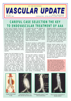


© Copyright 2026