
Installation Instructions
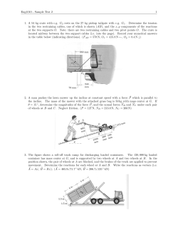
16-010
3.5 inch
A-Arm Lift Kit
will fit CLUB CAR® PRECEDENT®
installation instructions
included:
Main Suspension Assembly
2 Spindles
2 A-Arms
2 Rear Shock
Mounting Plates
2 Rear Lift
Blocks
2 U-Bolts
WARNING:
1
After installing this lift kit, the front wheels must be properly aligned. Failure to properly align the front
wheels may result in decreased ability to control the Golf Cart which may result in a rollover or crash.
Engage Park Brake. Raise cart with lift
and support with jack stands.
2
Remove front bumper. Retain hardware
3
Remove front wheels.
4
Remove nut and hub. Retain hub
and hardware.
5
Remove bolt from shock. Push shock up and
out of the way.
6
Remove nut from tie rod ends and detach tie
rods from spindles. Retain hardware.
7
Remove factory spindle and kingpin.
Retain hardware.
8
Remove spring plate and leaf spring. Retain
spring plate.
9
Remove three bolts from rack and pinion.
10
Remove factory A-Arms. Retain hardware.
11
Attach supplied A-Arm using hardware
retained from Step 10.
12
Reattach rack and pinion using hardware
retained from Step 9.
13
Using spring plate retained from Step 8,
attach Main Suspension Assembly using
supplied M10x40mm hex head bolts.
14
Apply thread locking adhesive to supplied
spindle bolts. Attach Spindles to Main
Suspension Assembly.
15
Reattach tie rod to spindles.
16
Reattach shock to A-Arm using hardware
retained from Step 5.
17
Reattach hub using hardware retained from
Step 4.
18
Reinstall bumper using hardware from
Step 2. Reinstall wheels and lower cart.
19
Chock front wheels. Lift rear of cart
and support with jack stands. Remove
rear wheels. Leave jack in place under
axle and motor aseembly.
20
IMPORTANT: Loosen, but do not remove,
factory U-Bolts on passenger’s side.
21
Use jack to lower axle and motor assembly
as needed for steps 22-29.
IMPORTANT: Only use jack to keep axle
and motor assembly at correct height, do not
lift cart.
22
Remove nut and lower bushing from shock
on Driver’s side. Remove factory U-Bolt.
23
Remove hardware from rear leaf spring
mount. Retain hardware.
24
Remove hardware from front leaf spring
mount. Retain hardware.
25
Use jack to lower axle and motor assembly.
Reinstall leaf spring on top of axle using
hardware retained from Steps 23 and 24.
26
Place Rear Lift Block under leaf spring.
IMPORTANT: Ensure that top of lift block
angles down toward the front of cart.
Ensure block angles
toward front of cart.
Place Rear Shock Mounting Plate over leaf
spring. Route supplied U-Bolt through Rear
Shock Mounting Plate as shown.
27
Attach bolt from hardware pack through
the factory lower bracket. This bolt does
not serve as a fastener, its only purpose to
provide the proper placement of the bracket
in the new assembly. Tighten hardware.
28
Route U-Bolt through factory bracket ensuring
that bolt attached in Step 27 fits properly into
hole in the axle. Tighten hardware.
29
Repeat steps 22-28 and use jack to lower
axle and motor assembly as needed.
Once complete, reinstall wheels, lower cart
and proceed with alignment as shown on
next page.
ALIGNMENT INSTRUCTIONS
WARNING:
After installing this lift kit, the front wheels must be properly aligned. Failure to properly align the front
wheels may result in decreased ability to control the Golf Cart which may result in a rollover or crash.
IMPORTANT: Both Camber and Toe must be
adjusted on this model.
Once installation is complete and the wheels have
been reinstalled, roll the cart forward 5-6 feet.
To adjust for proper camber, use a framing square,
level, or some other means of verifying that the
tire is at a 90 degree angle to the ground.
Ensure the wheels are pointing straight forward.
To adjust Toe, find a common point to measure
from on the inside front and inside rear of the front
tires. Adjust until the front measurement is 1/4” to
3/8” greater than the rear measurement.
C
To adjust camber (the vertical tilt of the wheels)
to 90 degrees using the two nuts on the bottom
heim joint (B).
If adjusting the camber to 90 degrees is not
possible using only the adjustment on the bottom
heim joint, then the top heim joint (C) must be
disconnected from the spindle and rotated as
necessary to achieve the correct camber.
A
IMPORTANT: Exposed tie rod threading should
be equal on both tie rods. Be sure to retighten all
adjustment points after adjustments are made.
To adjust toe-in/toe-out, loosen nut on tie rod end
(A). Adjust using a wrench to desired alignment.
B
IMPORTANT: Ensure that after this adjustment,
both wheels toe out from the cart’s centerline
equally.
Once tightened, roll the cart back 5-6 feet and
then forward again to check.
INSTALLATION COMPLETE
Visit www.mymadjax.com for more installation videos
Club Car®, Club Car® Precedent®, and Club Car® DS® are registered trademarks of Ingersoll Rand, Inc. (“Ingersoll Rand”). Reference to Club Car®,
Club Car® Precedent®, or Club Car® DS® or any of Ingersoll Rand’s trademarks, word marks, or products is only for purposes of identifying golf carts
with which this Madjax product is compatible. Madjax products are aftermarket parts and are not original equipment parts. Madjax is not connected to,
affiliated with, sponsored by, or endorsed by Ingersoll Rand or any of its subsidiary companies.


© Copyright 2026