
CKG1-XC88/XC89 -XC91
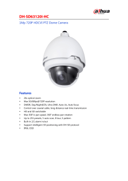
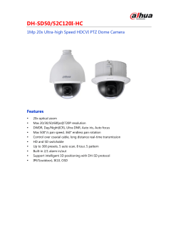
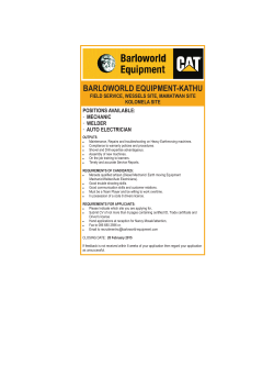
Spatter Resistant Cylinder for Arc Welding Clamp Cylinder/Magnetic Field Resistant Auto Switch (Rod Mounting Style) CKG1 ø40, ø50, ø63 -XC88/XC89 -XC91 RoHS How to Order Rod material Built-in auto switch magnet XC88 Stainless steel 304 XC89 S45C CKG1 A 50 100 Y Z P3DWSC XC89 CKG1 A 50 100 Y Z P3DWSC XC91 Clevis width A B Rod material 16.5 mm 19.5 mm XC91 Number of auto switches Bore size 40 50 63 Nil S n Thread type 40 mm 50 mm 63 mm Nil TN TF Rc1/4 NPT1/4 G1/4 Nil 50, 75, 100, 125, 150 50, 75, 100, 125, 150, 200 50, 75, 100, 125, 150, 200 Nil Y YA None Double knuckle joint (M6 without tap) Double knuckle joint (M6 with tap) Note) A knuckle pin, cotter pins and flat washers are provided. Nil Without auto switch (built-in magnet) Without switch mounting rod P Without auto switch (built-in magnet) With switch mounting rod Note) Select applicable auto switch models from the table below. Built-in Auto Switch Magnet Cylinder Part No. Made to Order Piston rod material (Hard chrome plated) -XC88 -XC89 -XC91 With air cushion on the unclamped side (head end) (Standard) W With air cushion on both ends Note) The dimensions of the product with the air cushion on both ends are the same as those of the product with the air cushion on the unclamped side (head end). Auto switch End bracket Part no. 2 pcs. 1 pc. “n” pcs. Cushion Cylinder stroke (mm) 40 50 63 S45C Coil scraper Luberetainer Grease for welding S45C Stainless steel 304 — — — — 1) Built-in auto switch magnet type without auto switch, without switch mounting rod Symbol for the auto switch type is "Nil" as shown below. (Example) CKG1A50-50YZ-XC89 2) Built-in auto switch magnet type without auto switch, with switch mounting rod Note) Use the -XC91 in a place where the distance from the welding portion is far and the spatter scattering is minimized. Symbol for the auto switch type is "P" as shown below. (Example) CKG1A50-50YZ-P-XC89 Applicable Auto Switches/Refer to the WEB catalog or the Best Pneumatics No.3 for further information on auto switches. Type Solid state auto switch Special function Auto switch model Magnetic field resistant (2-color indication) D-P3DWSC D-P3DWSE D-P3DW D-P3DWL D-P3DWZ D-P4DWSC D-P4DWSE D-P4DWL D-P4DWZ Electrical entry Indicator light Wiring (Pin no. in use) 2-wire (3−4) Pre-wired connector Lead wire length Applicable load 0.3 m 2-wire (1−4) 0.5 m Grommet Yes Pre-wired connector Grommet 3m 2-wire 24 VDC 2-wire (3−4) 2-wire (1−4) 2-wire Note 1) Please contact SMC for auto switches, auto switch proper mounting positions and operating ranges other than the above. Note 2) Refer to page 12 when ordering the auto switch mounting bracket assembly or switch mounting rod assembly. Note 3) For the D-P3DW, the auto switch and auto switch mounting bracket are packed together, (but not assembled). 7 Load voltage 5m 0.3 m 3m 5m Relay, PLC CKG1 ø40, ø50, ø63 -XC88/XC89 -XC91 Series Clamp Cylinders RoHS How to Order Rod material CKG1 A 50 100 Y Z M9BW XC89 CKG1 A 50 100 Y Z M9BW XC91 Rod material Clevis width XC91 Auto switch Bore size Nil 40 mm 50 mm 63 mm Nil S 2 pcs. 1 pc. ∗ For applicable auto switches, refer to the table below. ∗ Auto switches are shipped together, (but not assembled). Thread type Rc1/4 NPT1/4 G1/4 End bracket Nil Y YA Cylinder stroke (mm) 40 50, 75, 100, 125, 150 50 50, 75, 100, 125, 150, 200 63 50, 75, 100, 125, 150, 200 None Double knuckle joint (M6 without tap) Double knuckle joint (M6 with tap) Note 1) YA is equivalent to the conventional models. Note 2) A knuckle pin, cotter pins and flat washers are provided as a standard for Y and YA. Tubing Nil TN TF Number of auto switches Made to Order Part no. Piston rod material (Hard chrome plated) -XC88 -XC89 -XC91 Coil scraper Luberetainer Grease for welding S45C Stainless steel 304 — — — — Note) Use the -XC91 in a place where the distance from the welding portion is far and the spatter scattering is minimized. Caution The standard auto switch cannot be used in a magnetic field environment. For information on our cylinders that can be fitted with a magnetic field resistant auto switch, refer to page 7. Standard Auto Switches (Refer to the WEB catalog or the Best Pneumatics No.3 for detailed auto switch specifications.) Applicable cylinder series CKG1 Type Electrical entry Solid state auto switch Grommet Reed auto switch Grommet Note 1) Lead wire length symbol: 0.5 m……… 1 m……… 3 m……… 5 m……… Nil M L Z Indicator Wiring light (Output) Yes Yes M9BW M9BWM M9BWL M9BWZ 2-wire 2-wire Auto switch model Load voltage Lead wire length (m) DC AC Band mounting 0.5(Nil) 1(M) 3(L) 5(Z) M9B 5V 24 V — 12 V M9BW 100 V A93 24 V 12 V 100 V — B54 200 V Applicable load — Relay, PLC Note 2) Auto switches marked with “” are produced upon receipt of order. Note 3) Refer to page 13 when ordering the auto switch mounting bracket assembly. 8 Fittings 40 50 63 Without auto switch (Built-in magnet) S45C Detection Switches 16.5 mm 19.5 mm Flow Control Equipment A B Stainless steel 304 S45C Gas/Air Switching Valve XC88 XC89 Built-in auto switch magnet Spatter Resistant Cylinders for Arc Welding Spatter Resistant Cylinder for Arc Welding Clamp Cylinder with Standard Auto Switch (Band Mounting Style) CKG1-XC88/XC89 -XC91 Specifications 40 Bore size (mm) 50 Fluid 63 Air Proof pressure 1.5 MPa Maximum operating pressure 1.0 MPa Minimum operating pressure 0.05 MPa Ambient and fluid temperature –10°C to +60°C (No freezing) Piston speed 50 to 500 mm/s Cushion Note 1) Unclamped side (head end): With air cushion Speed controller Equipped on both ends Lubrication Non-lube +1.0 0 Stroke length tolerance Mounting Note 2) Double clevis Note 1) The model with air cushion on both ends (Symbol: W) is also available. Note 2) A clevis pin, cotter pins, flat washers are equipped as a standard. Clevis width Standard Strokes Bore size (mm) 40 50, 63 Standard stroke (mm) 50, 75, 100, 125, 150 50, 75, 100, 125, 150, 200 16.5 mm CKG1A 19.5 mm CKG1B End Bracket/Options Part no. Symbol Description Y YA Double knuckle joint M6 without tap (A knuckle pin, cotter pins, flat washers are equipped.) M6 with tap Series CKG1A Series CKG1B CKA-Y04 CKB-Y04 CKA-YA04 CKB-YA04 Weight (Basic weight includes the switch mounting rod. At 0 stroke) Unit: kg 40 50 63 Basic weight 0.76 0.98 1.18 Additional weight per 25 mm of stroke 0.11 0.12 0.14 Bore size (mm) Double knuckle joint (A knuckle pin, cotter pins, flat washers are equipped.) 0.34 Calculation Example) CKG150-100YZ-P-XC88 • Basic weight ··················· 1.03 (ø50) • Additional weight ············ 0.12/25 mm • Cylinder stroke ················ 100 mm • Double knuckle joint ········ 0.34 (Y) 1.03 + 0.12 x 100/25 + 0.34 = 1.85 kg Theoretical Output Unit: N Bore size (mm) 40 50 63 Rod size (mm) Operating pressure (MPa) Operating direction Piston area (mm2) 0.3 0.4 0.5 0.6 OUT 1260 378 504 630 756 IN 943 283 377 472 566 OUT 1960 588 784 980 1180 20 20 20 IN 1650 495 660 825 990 OUT 3120 934 1250 1560 1870 IN 2800 840 1120 1400 1680 Comparison of the Dimensions of Each Series (mm) Bore size (mm) 40 50 63 C B 9 A + Stroke ∗ At 0 stroke XC88, 89 XC91 Standard A B C A B C A B C 78 97 43 78 97 52 78 97 52 78 97 43 78 97 52 78 97 52 78 97 43 78 97 52 78 97 52 CKG1-XC88 -XC89 Bore Size ø40 to ø63 With auto switch (D-P4DWS). Cushion valve Top width across flats 3 17 20 14 11.5 39 S + Stroke (8.5) W 12 45° 45° 10 ø20 35 ø40 øIB øIA M16 x 1.5 Gas/Air Switching Valve s ≈H N 43 2 x Speed controller valve Top width across flats 3 45° Clamp Cylinders 3 x 1/4(Rc,NPT,G) Piping port 3 x 1/4(Rc,NPT,G) Piping port 6 4 x Hexagon bolt M6 x 20 L 8 ø3 R1 5 F −0.050 Width across flats 17 Shaft: ø12d9−0.093 Hole: 97 +0.027 ø12H8 0 78 + Stroke 190 + Stroke (mm) Clevis width +0.3 CKG1A: 16.5 0 +0.4 CKG1B: 19.5 0 Symbol Bore size 40 50 63 40 57 F Hs øIA øIB N S W 44 45.5 52 47 61 53 5 55 51 60 58 58 56 5.5 69 58.5 74 72 58 56 5.5 End Bracket Press-fit spring pin ø3 x 38 L 20 Material: Carbon steel 60 End bracket symbol Y (M6 without tap) YA (M6 with tap) Y (M6 without tap) YA (M6 with tap) Part no. Application CK-P04 Knuckle pin Clevis pin Flow Control Equipment 17 A 40 15 CKA-Y04 CKA-YA04 CKB-Y04 CKB-YA04 4 57 Note) Cotter pins and flat washers are attached to the pin. 45 Part no. 4 2 x M6 thread depth 11 (for YA type) 33 57 2 x M6 thread depth 11 (for YA type) Fittings 15 ø30 17 2 x ø3 20 20 Hole: +0.027 ø12H8 0 −0.050 19 Shaft: ø12d9−0.093 ø12d9−0.093 −0.050 Pin Tubing Double knuckle joint Detection Switches CKG140, 50, 63 -XC88 -XC89 Spatter Resistant Cylinders for Arc Welding Spatter Resistant Cylinder for Arc Welding Clamp Cylinder Material: Cast iron A (mm) Applicable clamp cylinder 16.5 +0.3 0 Series CKG1A 19.5 +0.4 0 Series CKG1B Note 1) A knuckle pin, cotter pins, flat washers and a spring pin are attached to the double knuckle joint. 10 CKG1-XC91 Bore Size ø40 to ø63 CKG140, 50, 63-XC91 With auto switch (D-P4DWS). Cushion valve Top width across flats 3 (Tube cover side only) 2 x Speed controller valve Top width across flats 3 M16 x 1.5 45° N 52 17 20 14 11.5 s 3 x 1/4 (Rc, NPT, G) Piping port S + Stroke 30 W øIB øIA ø20 35 40 8 ø3 F R1 5 Width across flats 17 4 x M6 x 12 45° 45° 10 3 ø30 ≈H 3 x 1/4 (Rc, NPT, G) Piping port -0.050 Shaft: ø12d9-0.093 +0.027 ø12H8 0 97 Hole: 78 + Stroke 190 + Stroke Clevis width CKG1A: 16.5 CKG1B: 19.5 40 57 11 (mm) +0.3 +0 +0.4 +0 Symbol Bore size 40 50 63 F Hs øIA øIB N S W 44 45.5 52 47 52 53 5 55 51 60 58 49 56 5.5 69 58.5 74 72 49 56 5.5 A s ≈H Auto switch model Same surface Symbol A B Hs A B Hs D-P3DW B Different surfaces D-P4DW A 32 D-P4DW B 4 Unit: mm Auto switch set value and its height ø63 ø50 ø40 7 7 10.5 30 30 23.5 56.5 49.5 43.5 8 4.5 4.5 20.5 27.5 27.5 45.5 51 58.5 Note 1) The mounting position should be referred for reference only for the auto switch mounting position at the stroke end detection. Adjust the auto switch after confirming the operation to set actually. Note 2) A/B dimensions are the distance from the standard position (above drawing) to the end surface of the auto switch. Note 3) The auto switch mounting position is temporarily set at the time of shipping from our factory. Change it to the desired position in accordance to your facility. s ≈H Minimum Stroke for Auto Switch Mounting Operating Range Unit: mm Auto switch model With 1 pc. D-P3DW D-P4DW 15 50 With 2 pcs. Different surfaces Same surface 30 75 50 Unit: mm Bore size Auto switch model D-P3DW D-P4DW 40 50 63 4 4 5 4 6 4.5 Note) When two D-P3DW are mounted to the cylinder with stroke 50 mm, mount them on different surfaces. Spatter Resistant Cylinders for Arc Welding Auto Switch Mounting Position and Its Height Rod mounting D-P3DW Clamp Cylinders Auto Switch Proper Mounting Position (Detection at Stroke End) and Its Mounting Height Gas/Air Switching Valve Magnetic Field Resistant Auto Switch Mounting Detection Switches CKG1-XC88/XC89 -XC91 Auto Switch Mounting Bracket/Part No. Tubing Switch mounting rod assembly/Auto switch mounting bracket assembly Collar Switch mounting rod Auto switch mounting bracket Sw itch mo unt ing BMB9-050S rod ass em bly Hexagon socket head button bolt (M4 tightening torque: 1.0 to 1.2 N·m) Auto switch (D-P3DW) Hexagon socket head cap screw (M4 tightening torque: 1 to 1.2 N·m) Switch mounting rod Fittings Hexagon socket head cap screw (Included with auto switch) (M2.5 x 9.5 L tightening torque: 0.2 to 0.3 N·m) Switch Mounting Rod Assembly/Part No. Series CKG140/50/ 63 Applicable clamp cylinder CKG140-50 CKG150-50/CKP150-50 CKG163-50/CKP163-50 CKG140-75 CKG150-75/CKP150-75 CKG163-75/CKP163-75 CKG140-100 CKG150-100/CKP150-100 CKG163-100/CKP163-100 CKG140-125 CKG150-125/CKP150-125 CKG163-125/CKP163-125 CKG140-150 CKG150-150/CKP150-150 CKG163-150/CKP163-150 Part no. CKG40-R050 CKG40-R075 CKG40-R100 CKG40-R125 CKG40-R150 Auto Switch Mounting Bracket Assembly/Part No. Applicable cylinder series Series CKG1 Auto switch mounting bracket part no. Applicable auto switch model 40 50 63 D-P3DW BMB9-050S D-P4DW BK1T-040 12 Flow Control Equipment Applicable series CKG1-XC88/XC89 -XC91 Standard Auto Switch Mounting Please contact SMC for detailed dimensions, specifications and lead times. Auto Switch Mounting Position (Detection at Stroke End) and Its Mounting Height D-M9B/A93(W) Minimum Stroke for Auto Switch Mounting (mm) ≈Hs A B 22 Auto switch With 2 pcs. With 2 pcs. With 1 pc. (Different surfaces) (Same surface) model 10.5 16.5 D-M9B D-M9BW D-A93 D-B54 D-B54 B 33 24.5 A 50 50 50 50 75 Auto Switch Mounting Position and Its Height (mm) 8.5 ≈Hs 50 12 Caution As for the precautions on the auto switches, product specifications, refer to the WEB catalog or Best Pneumatics No.3. Auto Switch Mounting Bracket Assembly/Part No. Auto switch set value and its height Auto switch Symbol model ø63 ø50 ø40 A 11.5 11.5 15 D-M9B B 34.5 34.5 27.5 D-M9BW Hs 48 41 35.5 A 7.5 7.5 11 D-A93 B 30.5 30.5 23.5 Hs 48 41 35.5 A 2 2 5.5 D-B54 B 25 25 18 Hs 50.5 43.5 38 Note 1) The mounting position should be referred for reference only for the auto switch mounting position at the stroke end detection. Adjust the auto switch after confirming the operation to set actually. Note 2) A/B dimensions are the distance from the standard position (above drawing) to the end surface of the auto switch. Note 3) The auto switch mounting position is temporarily set at the time of shipping from our factory. Change it to the desired position in accordance to your facility. Operating Range (mm) Auto switch model D-M9B D-M9BW D-A93 D-B54 ø40 Bore size (mm) ø50 ø63 Note) Note) Note) BMA3-040 BMA3-050 BMA3-063 BA-04 BA-05 BA-06 Note) This is the set part number for the auto switch mounting band (BMA2-A) and holder set (BJ5-1/switch bracket: transparent). The switch bracket (nylon) cannot be used in environments exposed to alcohol, chloroform, methylamines, hydrochloric acid and sulfuric acid, as this part will deteriorate. Please consult with SMC regarding other chemicals. 13 Auto switch model D-M9B D-M9BW D-A93 D-B54 40 3.5 5.5 8 10 Bore size 50 4 6.5 8 10 63 4 7 9 11 ∗ Values which include hysteresis are for guideline purpose only, they are not a guarantee (assuming approximately ±30% dispersion) and may change substantially depending on the ambient environment. Clamp Cylinders RoHS How to Order Cylinder stroke (mm) Rod material 50, 75, 100, 125, 150, 175, 200 50, 75, 100, 125, 150, 175, 200 CKGA 80 100 Y P4DWSC XC89 CKGA 80 100 Y P4DWSC XC91 Built-in auto switch magnet Bore size 80 100 End bracket 80 mm 100 mm Nil Y None Double knuckle joint (with tap) Nil Without auto switch (Built-in magnet) Without switch mounting rod P Without auto switch (Built-in magnet) With switch mounting rod Made to Order S45C Number of auto switches Nil S 2 pcs. 1 pc. Built-in Auto Switch Magnet Cylinder Part No. Piston rod material (Hard chrome plated) Coil scraper Luberetainer Grease for welding S45C Stainless steel 304 — — — — -XC88 -XC89 -XC91 XC91 Note) Select applicable auto switch models from the table below. Note) A knuckle pin, cotter pins and flat washers are provided for Y. Part no. Rod material Auto switch Clevis width: 28 mm Gas/Air Switching Valve XC88 Stainless steel 304 XC89 S45C 1) Built-in auto switch magnet type without auto switch, without switch mounting rod Symbol for the auto switch type is "Nil" as shown below. (Example) CKGA80-50Y-XC89 2) Built-in auto switch magnet type without auto switch, with switch mounting rod Note) Use the -XC91 in a place where the distance from the welding portion is far and the spatter scattering is minimized. Symbol for the auto switch type is "P" as shown below. (Example) CKGA80-50Y-P-XC89 Applicable Auto Switches/Refer to the WEB catalog or the Best Pneumatics No.3 for further information on auto switches. Special function Auto switch model Solid state auto switch Magnetic field resistant (2-color indication) D-P4DWSC D-P4DWSE D-P4DWL D-P4DWZ Electrical entry Indicator light Load voltage 2-wire (3−4) Pre-wired connector Yes Grommet Wiring (Pin no. in use) 2-wire (1−4) 2-wire Lead wire length 0.3 m 24 VDC 3m Applicable load Relay, PLC 5m Fittings Type Note) Please contact SMC for auto switches, auto switch proper mounting positions and operating ranges other than the above. Specifications Bore size (mm) Comparison of the Dimensions of Each Series 80 100 Fluid Tubing 80 100 Detection Switches CKGA ø80, ø100 -XC88/XC89 -XC91 Spatter Resistant Cylinders for Arc Welding Spatter Resistant Cylinder for Arc Welding Clamp Cylinder (Rod Mounting Style) The -XC88/XC89/XC91 and standard product have the same dimensions. Air Proof pressure 1.0 MPa Minimum operating pressure 0.05 MPa Ambient and fluid temperature Piston speed Cushion Flow Control Equipment 1.5 MPa Maximum operating pressure –10°C to +60°C (No freezing) 50 to 500 mm/s With air cushion on both ends Speed controller Equipped on both ends Lubrication Non-lube +1.0 0 Stroke length tolerance Mounting Note) Double clevis Note) A clevis pin, cotter pins and flat washers are provided. Clevis width 28 mm CKGA 14 CKGA-XC88/XC89 -XC91 Bore Size ø80 to ø100 CKGA80 -XC88/XC89 -XC91 With auto switch (D-P4DWS). 60 ≈68.5 60 54 + Stroke 35 10 30 1111 40 27 10 15 3 x Rc3/8 3 x Rc3/8 Speed controller valve Top width across flats 3 Cushion valve Top width across flats 3 45° 45° Width across flats 85 M20 x 1.5 ø95 ø62 ax .5 8 ø46 M ax .5 8 M 4 x M6 Thread depth 15 50 ø25 ø44 Width across flats 22 0 R2 +0.027 0 −0.050 Hole: ø18 Shaft: ø18−0.093 +0.5 28+0.1 55 110 129 + Stroke 75 258 + Stroke 2 x M6 Thread depth 6 +0.027 0 −0.050 ø18−0.093 Hole: ø18 33 Shaft: 34 17 +0.5 24 34 28+0.1 55 75 47 ø36 17 Press-fit spring pin ø3 x 38 L 2 x M6 Thread depth 6 21 71 90 Double knuckle joint Part No. ¡Double knuckle joint assembly part no.: C1K80-18-9261P-R Pin, flat washer, cotter pin, spring pin included ¡Pin assembly part no.: C1K80-23-9034P-R Pin, flat washer (2 pcs.), cotter pin (2 pcs.) ¡Tie-rod assembly part no. for auto switch mounting: C1K80E-B0467-050-R Stroke 050, 075, 100, 125, 150 ¡Auto switch mounting bracket (D-P4DW) part no.: BAP2-063 15 With auto switch (D-P4DWS). 56 ≈77.5 63 30 10 27 Speed control needle Top width across flats 4 43 34 10 10 14 3 x Rc3/8 3 x Rc3/8 Cushion valve Top width across flats 4 45° 45° 56 + Stroke 13 Width across flats 100 M24 x 1.5 M 24 −0.050 Shaft: ø18−0.093 +0.027 0 Hole: ø18 +0.5 28+0.1 61 110 129 + Stroke 85 259 + Stroke 2 x M6 Thread depth 6 −0.050 Shaft: ø18−0.093 17 ø38 +0.027 0 Hole: ø18 Detection Switches Press-fit spring pin ø5 x 40 L 32 37 Tubing 24 +0.5 28+0.1 61 85 48 25 70 90 Double knuckle joint Fittings 4 x M6 Thread depth 12 Part No. ¡Double knuckle joint assembly part no.: C1KA0-18-9262P-R Pin, flat washer, cotter pin, spring pin included ¡Pin assembly part no.: C1KA0-23-9035P-R Pin, flat washer (2 pcs.), cotter pin (2 pcs.) Flow Control Equipment 5 .6 ax ax Width across flats 24 ø52 Gas/Air Switching Valve M .6 5 50 ø30 ø112 ø44 R Spatter Resistant Cylinders for Arc Welding CKGA100 -XC88/XC89 -XC91 CKGA-XC88/XC89 -XC91 Clamp Cylinders Spatter Resistant Cylinder for Arc Welding Clamp Cylinder ¡Tie-rod assembly part no. for auto switch mounting: CK-A0E-B4657-050-R Stroke 050, 075, 100, 125, 150 ¡Auto switch mounting bracket (D-P4DW) part no.: BAP2-063 16


© Copyright 2026