
SPECIFICATIONS
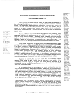
2007 Hummer H3
2007 ENGINE Engine Exhaust - H3
2007 ENGINE
Engine Exhaust - H3
SPECIFICATIONS
FASTENER TIGHTENING SPECIFICATIONS
Fastener Tightening Specifications
Specification
Metric
English
9 N.m
80 lb in
50 N.m
37 lb ft
Application
Catalytic Converter Heat Shield
Catalytic Converter Nut
Exhaust Manifold Bolt
First Pass
20 N.m
15 lb ft
Second Pass
20 N.m
15 lb ft
20 N.m
10 N.m
9 N.m
9 N.m
85 N.m
95 N.m
45 N.m
12.5 N.m
15 lb ft
89 lb in
80 lb in
80 lb in
63 lb ft
70 lb ft
33 lb ft
111 lb in
Final Pass
Exhaust Manifold Heat Shield Nut
Exhaust Muffler Heat Shield
Exhaust Pipe Heat Shield
Leaf Spring Bolt and Nut
Lower Shock Absorber Bolt and Nut
Muffler Nut
Transmission Filler Tube Bracket Nut
DIAGNOSTIC INFORMATION AND PROCEDURES
DIAGNOSTIC STARTING POINT - ENGINE EXHAUST
Begin the system diagnosis by reviewing the system Description and Operation. Reviewing the
information will help you determine the correct symptom diagnostic procedure when a
malfunction exists. It will also help you determine if the condition described by the customer is
normal operation. Refer to Symptoms - Engine Exhaust in order to identify the correct
procedure for diagnosing the system.
SYMPTOMS - ENGINE EXHAUST
Review the Exhaust System Description and Operation in order to familiarize yourself with
MY
Sunday, March 29, 2009 8:46:30
8:46:25 PM
Page 1
© 2005 Mitchell Repair Information Company, LLC.
2007 Hummer H3
2007 ENGINE Engine Exhaust - H3
the system functions. Refer to Exhaust System Description.
All diagnostics on a vehicle should follow a logical process. Strategy Based Diagnostics is a
uniform approach for repairing all systems. The diagnostic flow is the place to start when
repairs are necessary and may always be used in order to resolve a system problem. For a
detailed explanation, refer to Strategy Based Diagnosis .
Visual/Physical Inspection
Inspect for aftermarket or non-OEM devices such as, but not including; tailpipe extensions,
headers and exhaust cutouts. This could affect the operation and proper performance of the
exhaust system.
Verify the exact operating conditions under which the concern exists. Note factors such as
engine RPM, engine temperature, engine load and frequency of concern.
Inspect the easily accessible or visible system components for obvious damage or conditions
which could cause any symptom.
Intermittent
Test the vehicle under the same conditions that the customer reported in order to verify the system
is operating as designed.
Symptom List
Refer to a symptom diagnostic procedure from the following list in order to diagnose the
symptom:
Loss of power - Refer to Restricted Exhaust.
Poor acceleration - Refer to Restricted Exhaust.
Poor fuel economy - Refer to Restricted Exhaust.
Excessive smoke - diesel - Refer to Restricted Exhaust.
Exhaust hissing noise - Refer to Exhaust Leakage.
Exhaust popping noise - Refer to Exhaust Leakage.
Exhaust rattle noise - Refer to Exhaust Noise.
Loud exhaust noise - Refer to Exhaust Noise
Exhaust buzz, groan, hum noise - Refer to Exhaust Noise.
RESTRICTED EXHAUST
Tools Required
MY
Sunday, March 29, 2009 8:46:25 PM
Page 2
© 2005 Mitchell Repair Information Company, LLC.
2007 Hummer H3
2007 ENGINE Engine Exhaust - H3
J 35314-A Exhaust Back Pressure Gage. See Special Tools.
Diagnostic Aids
CAUTION: Refer to Hot Exhaust System Caution .
For dual exhaust systems a quick check of exhaust flow will help determine which side of the
exhaust system is restricted. The side that has less exhaust flow is the side that will be suspect and
diagnosis should begin there.
Test Description
The numbers below refer to the step numbers on the diagnostic table.
4: The exhaust system has very low back pressure under normal conditions. If the exhaust
system is restricted, a significant increase in the exhaust pressure is noticed on the J 35314A . See Special Tools. Removing the heated oxygen sensor (HO2S) may set a DTC. When
finishing this diagnostic table, be sure to clear all codes.
5: This step will isolate the catalytic converter from the remainder of the exhaust system.
8: Confirming that the condition has been fixed is essential. If the symptom still exists and
the vehicle has a dual exhaust system, proceed to step 2 and repeat diagnostic procedure on
the opposite exhaust pipe.
Restricted Exhaust
Step
Action
Did you verify the customers
1
complaint?
Did you review the exhaust
symptoms diagnostic information
2
and perform the necessary
inspections?
Is the system equipped with dual
exhaust?
3
Value(s)
-
-
-
Yes
No
Go to Step 2
-
Go to
Symptoms Engine
Go to Step 3 Exhaust
Go to
Diagnostic
Aids.
Go to Step 4
1. Remove the heated oxygen
sensor (HO2S) that is in front
of the catalytic converter.
Refer to Heated Oxygen
MY
Sunday, March 29, 2009 8:46:25 PM
Page 3
© 2005 Mitchell Repair Information Company, LLC.
2007 Hummer H3
2007 ENGINE Engine Exhaust - H3
2.
4
3.
4.
5.
Sensor 1 Replacement .
Install the J 35314-A Exhaust
Back Pressure Gage in place of
the HO2S sensor. See Special
Tools.
Start the engine.
9 kPa (1.25
Increase and monitor the
psi)
engine speed at 2,500 RPM.
Observe the exhaust system
back pressure reading on the
gage.
Does the reading exceed the
specified value?
5
Go to Step 5 Go to Step 8
1. Turn the engine off and place
the ignition in the lock
position.
2. Remove the J 35314-A . See
Special Tools.
3. Re-install the HO2S sensor.
Refer to Heated Oxygen
Sensor 1 Replacement .
4. Remove the post-catalyst
HO2S sensor. Refer to Heated
Oxygen Sensor 2
9 kPa (1.25
Replacement .
psi)
5. Install the J 35314-A in place
of the post HO2S sensor. See
Special Tools.
6. Start the engine.
7. Increase and monitor the
engine speed at 2,500 RPM.
8. Observe the exhaust system
back pressure reading on the
gage.
Does the reading exceed the
MY
Sunday, March 29, 2009 8:46:25 PM
Page 4
© 2005 Mitchell Repair Information Company, LLC.
2007 Hummer H3
2007 ENGINE Engine Exhaust - H3
specified value?
Inspect the exhaust system for the
following conditions:
6
7
8
Go to Step 6 Go to Step 7
Damage in the exhaust pipe
Debris in the exhaust pipe
Muffler or resonator internal
failure
Two-layer exhaust pipe
separation
Did you find and correct the
condition?
Replace the catalytic converter.
Refer to Catalytic Converter
Replacement.
Did you find and correct the
condition?
-
Go to Step 8
-
Go to Step 8
-
-
1. Remove the J 35314-A . See
Special Tools.
2. Reinstall the applicable HO2S
sensor. Refer to the following:
Heated Oxygen Sensor
1 Replacement
Heated Oxygen Sensor
2 Replacement
3. Clear any codes.
4. Road test the vehicle in order
to verify the repair.
-
Did you correct the condition?
System OK Go to Step 2
EXHAUST LEAKAGE
Exhaust Leakage
Condition
Action
MY
Sunday, March 29, 2009 8:46:25 PM
Page 5
© 2005 Mitchell Repair Information Company, LLC.
2007 Hummer H3
2007 ENGINE Engine Exhaust - H3
CAUTION:
Refer to Hot Exhaust System Caution .
DEFINITION: An exhaust leak may show stains at the area of the leak. The leak may be
felt by holding a hand close to the suspected areas or using a smoke pencil. The leak may
make a popping or hissing noise.Refer to Symptoms - Engine Exhaust prior to beginning
this table.
Misaligned or improperly
Align and tighten the exhaust system components to the
installed exhaust system
specifications. Refer to Fastener Tightening
components
Specifications.
Ensure the exhaust hangers are in the proper locations
and not loose. Refer to Exhaust System Insulator,
Hanger, Bracket Replacement.
Exhaust leaks at the
Tighten the components to the specifications. Refer to
following connections:
Fastener Tightening Specifications.
Exhaust manifold to
pipe
Flanges
Pipe clamps
Seals or gaskets leaking:
Exhaust manifold to
cylinder head
Catalytic converter to
exhaust manifold
Catalytic converter to
muffler
Irregularities at the mating
surfaces on the flange
connections
Exhaust manifold cracked or
broken
Exhaust system component
connection welds leaking
Muffler or resonator, if
equipped, damaged or
Replace the leaking seal or gasket. Refer to the following:
Exhaust Manifold Replacement
Exhaust Seal Replacement
Repair as required or replace the affected component. Refer
to the affected components procedure for service.
Replace the exhaust manifold. Refer to Exhaust Manifold
Replacement.
Replace the leaking component. Refer to the affected
component's procedure for service.
Replace the affected muffler or resonator, if equipped. Refer
to Muffler Replacement.
MY
Sunday, March 29, 2009 8:46:25 PM
Page 6
© 2005 Mitchell Repair Information Company, LLC.
2007 Hummer H3
2007 ENGINE Engine Exhaust - H3
leaking at the seams
EXHAUST NOISE
Exhaust Noise
Condition
Action
CAUTION:
Refer to Hot Exhaust System Caution .
IMPORTANT:
Refer to Symptoms - Engine Exhaust prior to beginning this table.
DEFINITION: An audible or physical noise due to a faulty component or damaged
components causing a loose or misaligned exhaust system resulting in a rattle or vibration
noise.
Popping or hissing noise
Exhaust leak. Refer to Exhaust Leakage.
Loud exhaust
1. Compare to a known good vehicle.
2. Inspect for a damaged or failed muffler.
3. Replace the faulty muffler. Refer to Muffler
Replacement.
External rattle or vibration noise
1. Inspect for a bent or loose hanger, loose heat shield
or loose clamp.
2. Inspect for a exhaust pipe causing interference.
3. Repair or replace the affected component. Refer to
the affected component's service procedure.
Internal rattle
1. Test the components by tapping with a rubber mallet
to confirm a rattle.
2. Replace the faulty catalytic converter, resonator or
muffler. Refer to one of the following procedures:
Catalytic Converter Replacement
Muffler Replacement
REPAIR INSTRUCTIONS
EXHAUST MANIFOLD REPLACEMENT
Removal Procedure
MY
Sunday, March 29, 2009 8:46:25 PM
Page 7
© 2005 Mitchell Repair Information Company, LLC.
2007 Hummer H3
2007 ENGINE Engine Exhaust - H3
CAUTION: Refer to Exhaust Service Caution .
CAUTION: Refer to Protective Goggles and Glove Caution .
Fig. 1: View Of Exhaust Manifold
Courtesy of GENERAL MOTORS CORP.
1. Remove the secondary air injection (AIR) check valve. Refer to Secondary Air Injection
Check Valve Replacement .
2. Remove the exhaust seal. Refer to Exhaust Seal Replacement.
3. Remove the exhaust manifold heat shield. Refer to Exhaust Manifold Heat Shield
MY
Sunday, March 29, 2009 8:46:25 PM
Page 8
© 2005 Mitchell Repair Information Company, LLC.
2007 Hummer H3
2007 ENGINE Engine Exhaust - H3
Replacement.
4. Remove the exhaust manifold bolts.
5. Remove the exhaust manifold.
Fig. 2: View Of Exhaust Manifold Gasket
Courtesy of GENERAL MOTORS CORP.
6. Remove and discard the exhaust manifold gasket.
7. Clean and inspect the exhaust manifold. Refer to Exhaust Manifold Cleaning and
Inspection .
Installation Procedure
MY
Sunday, March 29, 2009 8:46:25 PM
Page 9
© 2005 Mitchell Repair Information Company, LLC.
2007 Hummer H3
2007 ENGINE Engine Exhaust - H3
Fig. 3: View Of Exhaust Manifold Gasket
Courtesy of GENERAL MOTORS CORP.
1. Clean and apply threadlock GM P/N 12345493 (Canadian P/N 10953488) to the exhaust
manifold bolt threads.
2. Position a NEW exhaust manifold gasket onto the cylinder head.
MY
Sunday, March 29, 2009 8:46:25 PM
Page 10
© 2005 Mitchell Repair Information Company, LLC.
2007 Hummer H3
2007 ENGINE Engine Exhaust - H3
Fig. 4: View Of Exhaust Manifold
Courtesy of GENERAL MOTORS CORP.
3. Position the exhaust manifold against cylinder head.
4. Install the exhaust manifold bolts.
MY
Sunday, March 29, 2009 8:46:25 PM
Page 11
© 2005 Mitchell Repair Information Company, LLC.
2007 Hummer H3
2007 ENGINE Engine Exhaust - H3
Fig. 5: View Of Bolt Sequence For Exhaust Manifold
Courtesy of GENERAL MOTORS CORP.
NOTE:
Refer to Fastener Notice .
5. Tighten the exhaust manifold bolts.
Tighten:
MY
Sunday, March 29, 2009 8:46:25 PM
Page 12
© 2005 Mitchell Repair Information Company, LLC.
2007 Hummer H3
2007 ENGINE Engine Exhaust - H3
1. Tighten the bolts a first pass in sequence to 20 N.m (15 lb ft).
2. Tighten the bolts a second pass in sequence to 20 N.m (15 lb ft).
3. Tighten the bolts a final pass in sequence to 20 N.m (15 lb ft).
6. Install the exhaust manifold heat shield. Refer to Exhaust Manifold Heat Shield
Replacement.
7. Install the exhaust seal. Refer to Exhaust Seal Replacement.
8. Install the AIR check valve. Refer to Secondary Air Injection Check Valve
Replacement .
EXHAUST SEAL REPLACEMENT
Removal Procedure
CAUTION: Refer to Exhaust Service Caution .
CAUTION: Refer to Protective Goggles and Glove Caution .
1. Raise and support the vehicle. Refer to Lifting and Jacking the Vehicle .
MY
Sunday, March 29, 2009 8:46:25 PM
Page 13
© 2005 Mitchell Repair Information Company, LLC.
2007 Hummer H3
2007 ENGINE Engine Exhaust - H3
Fig. 6: View Of Catalytic Converter
Courtesy of GENERAL MOTORS CORP.
2. Remove the nuts attaching the catalytic converter to the exhaust manifold.
3. Position the exhaust system rearward, enough to allow clearance to remove the seal.
MY
Sunday, March 29, 2009 8:46:25 PM
Page 14
© 2005 Mitchell Repair Information Company, LLC.
2007 Hummer H3
2007 ENGINE Engine Exhaust - H3
Fig. 7: View Of Exhaust Manifold Seal
Courtesy of GENERAL MOTORS CORP.
4. Remove and discard the exhaust manifold seal.
Installation Procedure
MY
Sunday, March 29, 2009 8:46:25 PM
Page 15
© 2005 Mitchell Repair Information Company, LLC.
2007 Hummer H3
2007 ENGINE Engine Exhaust - H3
Fig. 8: View Of Exhaust Manifold Seal
Courtesy of GENERAL MOTORS CORP.
1. Install a NEW seal to the exhaust manifold flange.
MY
Sunday, March 29, 2009 8:46:26 PM
Page 16
© 2005 Mitchell Repair Information Company, LLC.
2007 Hummer H3
2007 ENGINE Engine Exhaust - H3
Fig. 9: View Of Catalytic Converter
Courtesy of GENERAL MOTORS CORP.
2. Position the catalytic converter to the exhaust manifold.
NOTE:
Refer to Fastener Notice .
3. Install the nuts attaching the catalytic converter to the exhaust manifold.
Tighten: Tighten the nuts to 50 N.m (37 lb ft).
MY
Sunday, March 29, 2009 8:46:26 PM
Page 17
© 2005 Mitchell Repair Information Company, LLC.
2007 Hummer H3
2007 ENGINE Engine Exhaust - H3
4. Lower the vehicle.
CATALYTIC CONVERTER REPLACEMENT
Removal Procedure
CAUTION: Refer to Exhaust Service Caution .
CAUTION: Refer to Protective Goggles and Glove Caution .
MY
Sunday, March 29, 2009 8:46:26 PM
Page 18
© 2005 Mitchell Repair Information Company, LLC.
2007 Hummer H3
2007 ENGINE Engine Exhaust - H3
Fig. 10: View Of HO2S Electrical Connector
Courtesy of GENERAL MOTORS CORP.
1. Remove the right torsion bar. Refer to Torsion Bar Replacement .
2. Disconnect the heated oxygen sensor (HO2S) at the sensor pigtail (3).
3. Remove the HO2S if replacement is necessary. Refer to Heated Oxygen Sensor 2
Replacement .
MY
Sunday, March 29, 2009 8:46:26 PM
Page 19
© 2005 Mitchell Repair Information Company, LLC.
2007 Hummer H3
2007 ENGINE Engine Exhaust - H3
MY
Sunday, March 29, 2009 8:46:26 PM
Page 20
© 2005 Mitchell Repair Information Company, LLC.
2007 Hummer H3
2007 ENGINE Engine Exhaust - H3
Fig. 11: View Of Exhaust Hanger And Exhaust Muffler Hanger Rod
Courtesy of GENERAL MOTORS CORP.
IMPORTANT: Do not use oil base lubricants.
4. Apply a soapy solution to the exhaust muffler hanger rod (3) in order to ease the removal of
the exhaust hanger (2), if necessary.
5. Pry the exhaust hanger (2) free from the exhaust muffler hanger rod (3), if necessary.
Fig. 12: View Of Nuts Securing Muffler To Catalytic Converter
Courtesy of GENERAL MOTORS CORP.
6. Remove the nuts securing the muffler to the catalytic converter.
MY
Sunday, March 29, 2009 8:46:26 PM
Page 21
© 2005 Mitchell Repair Information Company, LLC.
2007 Hummer H3
2007 ENGINE Engine Exhaust - H3
7. Position the muffler rearward enough to allow the studs located in the muffler to clear the
catalytic converter pipe flange.
Fig. 13: View Of Catalytic Converter
Courtesy of GENERAL MOTORS CORP.
8. Remove the nuts attaching the catalytic converter to the exhaust manifold.
9. Remove the catalytic converter.
MY
Sunday, March 29, 2009 8:46:26 PM
Page 22
© 2005 Mitchell Repair Information Company, LLC.
2007 Hummer H3
2007 ENGINE Engine Exhaust - H3
Fig. 14: View Of Exhaust Manifold Seal
Courtesy of GENERAL MOTORS CORP.
10. Remove and discard the exhaust manifold seal at the exhaust manifold flange.
Installation Procedure
MY
Sunday, March 29, 2009 8:46:26 PM
Page 23
© 2005 Mitchell Repair Information Company, LLC.
2007 Hummer H3
2007 ENGINE Engine Exhaust - H3
Fig. 15: View Of Exhaust Manifold Seal
Courtesy of GENERAL MOTORS CORP.
1. Install a NEW seal to the exhaust manifold flange.
MY
Sunday, March 29, 2009 8:46:26 PM
Page 24
© 2005 Mitchell Repair Information Company, LLC.
2007 Hummer H3
2007 ENGINE Engine Exhaust - H3
Fig. 16: View Of Catalytic Converter
Courtesy of GENERAL MOTORS CORP.
NOTE:
Refer to Exhaust System Inspection Notice .
2. Install the catalytic converter to the exhaust manifold.
3. Install the nuts attaching the catalytic converter to the exhaust manifold. Do not tighten at
this time.
MY
Sunday, March 29, 2009 8:46:26 PM
Page 25
© 2005 Mitchell Repair Information Company, LLC.
2007 Hummer H3
2007 ENGINE Engine Exhaust - H3
Fig. 17: View Of Nuts Securing Muffler To Catalytic Converter
Courtesy of GENERAL MOTORS CORP.
4. Align the catalytic converter with the studs located in the muffler.
NOTE:
Refer to Fastener Notice .
5. Install the nuts securing the muffler to the catalytic converter. Tighten the nuts by hand until
each contacts the metal flange.
Tighten: Tighten the nuts to 45 N.m (33 lb ft).
6. Tighten the catalytic converter nuts previously installed in step 3.
MY
Sunday, March 29, 2009 8:46:26 PM
Page 26
© 2005 Mitchell Repair Information Company, LLC.
2007 Hummer H3
2007 ENGINE Engine Exhaust - H3
Tighten: Tighten the nuts to 50 N.m (37 lb ft).
7. Install the HO2S if previously removed. Refer to Heated Oxygen Sensor 2 Replacement .
MY
Sunday, March 29, 2009 8:46:26 PM
Page 27
© 2005 Mitchell Repair Information Company, LLC.
2007 Hummer H3
2007 ENGINE Engine Exhaust - H3
MY
Sunday, March 29, 2009 8:46:26 PM
Page 28
© 2005 Mitchell Repair Information Company, LLC.
2007 Hummer H3
2007 ENGINE Engine Exhaust - H3
Fig. 18: View Of Exhaust Hanger And Exhaust Muffler Hanger Rod
Courtesy of GENERAL MOTORS CORP.
IMPORTANT: Do not use oil base lubricants.
8. Apply a soapy solution to the following in order to ease the installation of the hanger (2):
The inner diameter of the exhaust muffler hanger (2)
The exhaust muffler hanger rod (3)
Fig. 19: View Of HO2S Electrical Connector
MY
Sunday, March 29, 2009 8:46:26 PM
Page 29
© 2005 Mitchell Repair Information Company, LLC.
2007 Hummer H3
2007 ENGINE Engine Exhaust - H3
Courtesy of GENERAL MOTORS CORP.
9. Connect the HO2S at the pigtail (3).
10. Install the right torsion bar. Refer to Torsion Bar Replacement .
EXHAUST SYSTEM INSULATOR, HANGER, BRACKET REPLACEMENT
Removal Procedure
CAUTION: Refer to Exhaust Service Caution .
CAUTION: Refer to Protective Goggles and Glove Caution .
1. Raise and support the vehicle. Refer to Lifting and Jacking the Vehicle .
IMPORTANT: Service the exhaust hangers individually in order to retain
the support of the exhaust system.
MY
Sunday, March 29, 2009 8:46:26 PM
Page 30
© 2005 Mitchell Repair Information Company, LLC.
2007 Hummer H3
2007 ENGINE Engine Exhaust - H3
Fig. 20: View Of Exhaust Pipe Hanger
Courtesy of GENERAL MOTORS CORP.
IMPORTANT: Do not use oil base lubricants.
2. Apply a soapy solution to the following in order to ease the removal of the hanger (1):
The frame support bracket rod (2)
The exhaust pipe hanger rod (3)
3. Pry the exhaust pipe hanger (1) free from the following:
MY
Sunday, March 29, 2009 8:46:26 PM
Page 31
© 2005 Mitchell Repair Information Company, LLC.
2007 Hummer H3
2007 ENGINE Engine Exhaust - H3
The frame support bracket rod (2)
The exhaust pipe hanger rod (3)
Installation Procedure
Fig. 21: View Of Exhaust Pipe Hanger
Courtesy of GENERAL MOTORS CORP.
IMPORTANT: Do not use oil base lubricants.
MY
Sunday, March 29, 2009 8:46:26 PM
Page 32
© 2005 Mitchell Repair Information Company, LLC.
2007 Hummer H3
2007 ENGINE Engine Exhaust - H3
1. Apply a soapy solution to the following in order to ease the installation of the hanger (1):
The frame support bracket rod (2)
The inner diameter of the exhaust pipe hanger (1)
The exhaust pipe hanger rod (3)
2. Press the exhaust pipe hanger (1) over the following:
The frame support bracket rod (2)
The exhaust pipe hanger rod (3)
3. Lower the vehicle.
MUFFLER REPLACEMENT
Removal Procedure
CAUTION: Refer to Exhaust Service Caution .
CAUTION: Refer to Protective Goggles and Glove Caution .
1. Raise and support the vehicle. Refer to Lifting and Jacking the Vehicle .
MY
Sunday, March 29, 2009 8:46:26 PM
Page 33
© 2005 Mitchell Repair Information Company, LLC.
2007 Hummer H3
2007 ENGINE Engine Exhaust - H3
Fig. 22: View Of Rear Right Wheel Suspension Assembly
Courtesy of GENERAL MOTORS CORP.
IMPORTANT: Use care not to over extend the rear brake hose.
2. Complete the following in order to gain clearance to remove the muffler:
1. Remove the lower shock absorber nuts (9) and bolts (8).
2. Remove the right rear leaf spring nut (2) and bolt (1).
3. Wedge a block of wood (5) between the frame (4) and the rear axle (6).
MY
Sunday, March 29, 2009 8:46:26 PM
Page 34
© 2005 Mitchell Repair Information Company, LLC.
2007 Hummer H3
2007 ENGINE Engine Exhaust - H3
Fig. 23: View Of Nuts Securing Muffler To Catalytic Converter
Courtesy of GENERAL MOTORS CORP.
3. Remove the nuts securing the muffler to the catalytic converter.
MY
Sunday, March 29, 2009 8:46:26 PM
Page 35
© 2005 Mitchell Repair Information Company, LLC.
2007 Hummer H3
2007 ENGINE Engine Exhaust - H3
MY
Sunday, March 29, 2009 8:46:26 PM
Page 36
© 2005 Mitchell Repair Information Company, LLC.
2007 Hummer H3
2007 ENGINE Engine Exhaust - H3
Fig. 24: View Of Exhaust Hanger & Exhaust Muffler Hanger Rod
Courtesy of GENERAL MOTORS CORP.
IMPORTANT: Do not use oil base lubricants.
4. Apply a soapy solution to the exhaust muffler hanger rod (3) in order to ease the removal of
the exhaust hanger (1).
5. Pry the exhaust hanger (1) free from the exhaust muffler hanger rod (3).
MY
Sunday, March 29, 2009 8:46:26 PM
Page 37
© 2005 Mitchell Repair Information Company, LLC.
2007 Hummer H3
2007 ENGINE Engine Exhaust - H3
MY
Sunday, March 29, 2009 8:46:26 PM
Page 38
© 2005 Mitchell Repair Information Company, LLC.
2007 Hummer H3
2007 ENGINE Engine Exhaust - H3
Fig. 25: Identifying Exhaust Hanger & Exhaust Muffler Hanger Rod
Courtesy of GENERAL MOTORS CORP.
IMPORTANT: Do not use oil base lubricants.
6. Apply a soapy solution to the exhaust muffler hanger rod (2) in order to ease the removal of
the exhaust hanger (3).
7. Pry the exhaust hanger (3) free from the exhaust muffler hanger rod (2).
MY
Sunday, March 29, 2009 8:46:26 PM
Page 39
© 2005 Mitchell Repair Information Company, LLC.
2007 Hummer H3
2007 ENGINE Engine Exhaust - H3
MY
Sunday, March 29, 2009 8:46:26 PM
Page 40
© 2005 Mitchell Repair Information Company, LLC.
2007 Hummer H3
2007 ENGINE Engine Exhaust - H3
Fig. 26: View Of Exhaust Hanger And Exhaust Muffler Hanger Rod
Courtesy of GENERAL MOTORS CORP.
IMPORTANT: Do not use oil base lubricants.
8. Apply a soapy solution to the exhaust muffler hanger rod (3) in order to ease the removal of
the exhaust hanger (2).
9. Pry the exhaust hanger (2) free from the exhaust muffler hanger rod (3).
10. Complete the following in order to remove the muffler from the vehicle:
1. Slide the muffler rearward from the catalytic converter.
2. Rotate the muffler 90 degrees counterclockwise from the rear.
3. Carefully remove the muffler rearward from the vehicle.
Installation Procedure
1. Complete the following in order to install the muffler to the vehicle:
1. With the muffler turned 90 degrees counterclockwise from the rear, carefully insert the
muffler over the rear axle until the flange is near the catalytic converter.
2. Rotate the muffler clockwise 90 degrees to the installed position.
3. Slide the muffler forward into position, aligning the studs with the rear of the catalytic
converter.
MY
Sunday, March 29, 2009 8:46:26 PM
Page 41
© 2005 Mitchell Repair Information Company, LLC.
2007 Hummer H3
2007 ENGINE Engine Exhaust - H3
MY
Sunday, March 29, 2009 8:46:26 PM
Page 42
© 2005 Mitchell Repair Information Company, LLC.
2007 Hummer H3
2007 ENGINE Engine Exhaust - H3
Fig. 27: View Of Exhaust Hanger And Exhaust Muffler Hanger Rod
Courtesy of GENERAL MOTORS CORP.
IMPORTANT: Do not use oil base lubricants.
2. Apply a soapy solution to the following in order to ease the installation of the hanger (2):
The inner diameter of the exhaust muffler hanger (2)
The exhaust muffler hanger rod (3)
3. Press the exhaust muffler hanger (3) over the exhaust pipe hanger rod (1).
MY
Sunday, March 29, 2009 8:46:26 PM
Page 43
© 2005 Mitchell Repair Information Company, LLC.
2007 Hummer H3
2007 ENGINE Engine Exhaust - H3
MY
Sunday, March 29, 2009 8:46:26 PM
Page 44
© 2005 Mitchell Repair Information Company, LLC.
2007 Hummer H3
2007 ENGINE Engine Exhaust - H3
Fig. 28: Identifying Exhaust Hanger & Exhaust Muffler Hanger Rod
Courtesy of GENERAL MOTORS CORP.
IMPORTANT: Do not use oil base lubricants.
4. Apply a soapy solution to the following in order to ease the installation of the hanger (3):
The inner diameter of the exhaust muffler hanger (3)
The exhaust muffler hanger rod (2)
5. Press the exhaust muffler hanger (3) over the exhaust pipe hanger rod (1).
MY
Sunday, March 29, 2009 8:46:26 PM
Page 45
© 2005 Mitchell Repair Information Company, LLC.
2007 Hummer H3
2007 ENGINE Engine Exhaust - H3
MY
Sunday, March 29, 2009 8:46:26 PM
Page 46
© 2005 Mitchell Repair Information Company, LLC.
2007 Hummer H3
2007 ENGINE Engine Exhaust - H3
Fig. 29: View Of Exhaust Hanger & Exhaust Muffler Hanger Rod
Courtesy of GENERAL MOTORS CORP.
IMPORTANT: Do not use oil base lubricants.
6. Apply a soapy solution to the following in order to ease the installation of the hanger (1):
The inner diameter of the exhaust muffler hanger (1)
The exhaust muffler hanger rod (3)
7. Press the exhaust muffler hanger (1) over the exhaust pipe hanger rod (3).
Fig. 30: View Of Nuts Securing Muffler To Catalytic Converter
Courtesy of GENERAL MOTORS CORP.
MY
Sunday, March 29, 2009 8:46:26 PM
Page 47
© 2005 Mitchell Repair Information Company, LLC.
2007 Hummer H3
2007 ENGINE Engine Exhaust - H3
NOTE:
Refer to Fastener Notice .
8. Install the nuts securing the muffler to the catalytic converter. Tighten the muffler nuts by
hand until each contacts the metal flange.
Tighten: Tighten the nuts to 45 N.m (33 lb ft).
Fig. 31: View Of Rear Right Wheel Suspension Assembly
Courtesy of GENERAL MOTORS CORP.
9. Remove the block of wood (5) from between the frame (4) and rear axle (6).
10. Install the right rear leaf spring bolt (1) and nut (2).
Tighten: Tighten the bolt and nut to 85 N.m (63 lb ft).
MY
Sunday, March 29, 2009 8:46:26 PM
Page 48
© 2005 Mitchell Repair Information Company, LLC.
2007 Hummer H3
2007 ENGINE Engine Exhaust - H3
11. Install the lower shock absorber bolts (8) and nuts (9).
Tighten: Tighten the bolts and nuts to 95 N.m (70 lb ft).
12. Inspect the exhaust system for leaks and underbody contact.
13. Lower the vehicle.
CATALYTIC CONVERTER HEAT SHIELD REPLACEMENT
Removal Procedure
CAUTION: Refer to Exhaust Service Caution .
CAUTION: Refer to Protective Goggles and Glove Caution .
MY
Sunday, March 29, 2009 8:46:26 PM
Page 49
© 2005 Mitchell Repair Information Company, LLC.
2007 Hummer H3
2007 ENGINE Engine Exhaust - H3
MY
Sunday, March 29, 2009 8:46:26 PM
Page 50
© 2005 Mitchell Repair Information Company, LLC.
2007 Hummer H3
2007 ENGINE Engine Exhaust - H3
Fig. 32: View Of Catalytic Converter Heat Shield At Floor Panel
Courtesy of GENERAL MOTORS CORP.
1. Remove the catalytic converter. Refer to Catalytic Converter Replacement.
2. Remove the nuts securing the heat shield to the floor panel.
3. Remove the catalytic converter heat shield.
Installation Procedure
MY
Sunday, March 29, 2009 8:46:26 PM
Page 51
© 2005 Mitchell Repair Information Company, LLC.
2007 Hummer H3
2007 ENGINE Engine Exhaust - H3
MY
Sunday, March 29, 2009 8:46:27 PM
Page 52
© 2005 Mitchell Repair Information Company, LLC.
2007 Hummer H3
2007 ENGINE Engine Exhaust - H3
Fig. 33: View Of Catalytic Converter Heat Shield At Floor Panel
Courtesy of GENERAL MOTORS CORP.
1. Position the catalytic converter heat shield to the floor panel studs.
NOTE:
Refer to Fastener Notice .
2. Install the nuts securing the heat shield to the floor panel.
Tighten: Tighten the nuts to 9 N.m (80 lb in).
3. Remove the catalytic converter. Refer to Catalytic Converter Replacement.
EXHAUST MANIFOLD HEAT SHIELD REPLACEMENT
Removal Procedure
CAUTION: Refer to Exhaust Service Caution .
CAUTION: Refer to Protective Goggles and Glove Caution .
MY
Sunday, March 29, 2009 8:46:27 PM
Page 53
© 2005 Mitchell Repair Information Company, LLC.
2007 Hummer H3
2007 ENGINE Engine Exhaust - H3
Fig. 34: View Of Transmission Filler Tube & Bracket
Courtesy of GENERAL MOTORS CORP.
1. Remove the air cleaner outlet duct. Refer to Air Cleaner Outlet Duct Replacement .
2. Remove the air cleaner assembly. Refer to Air Cleaner Assembly Replacement .
3. If equipped with an automatic transmission, remove the transmission filler tube bracket nut
from the secondary air injection (AIR) adapter and position aside.
4. Remove the heated oxygen sensor (HO2S) from the exhaust manifold. Refer to Heated
Oxygen Sensor 1 Replacement .
MY
Sunday, March 29, 2009 8:46:27 PM
Page 54
© 2005 Mitchell Repair Information Company, LLC.
2007 Hummer H3
2007 ENGINE Engine Exhaust - H3
Fig. 35: View Of Exhaust Manifold Heat Shield
Courtesy of GENERAL MOTORS CORP.
5. Remove the nuts securing the heat shield to the exhaust manifold.
6. Remove the exhaust manifold heat shield.
Installation Procedure
MY
Sunday, March 29, 2009 8:46:27 PM
Page 55
© 2005 Mitchell Repair Information Company, LLC.
2007 Hummer H3
2007 ENGINE Engine Exhaust - H3
Fig. 36: View Of Exhaust Manifold Heat Shield
Courtesy of GENERAL MOTORS CORP.
1. Install the exhaust manifold heat shield to the exhaust manifold.
2. Apply anti-seize GM P/N 12371386 (Canadian P/N 993128) to the exhaust manifold heat
shield nuts.
NOTE:
Refer to Fastener Notice .
3. Install the exhaust manifold heat shield nuts.
Tighten: Tighten the nuts to 10 N.m (89 lb in).
4. Install the HO2S to the exhaust manifold. Refer to Heated Oxygen Sensor 1
Replacement .
MY
Sunday, March 29, 2009 8:46:27 PM
Page 56
© 2005 Mitchell Repair Information Company, LLC.
2007 Hummer H3
2007 ENGINE Engine Exhaust - H3
Fig. 37: View Of Transmission Filler Tube & Bracket
Courtesy of GENERAL MOTORS CORP.
5. Position the automatic transmission filler tube to the AIR adapter if previously removed.
6. Install the automatic transmission filler tube bracket nut.
Tighten: Tighten the nut to 12.5 N.m (111 lb in).
7. Install the air cleaner assembly. Refer to Air Cleaner Assembly Replacement .
8. Install the air cleaner outlet duct. Refer to Air Cleaner Outlet Duct Replacement .
EXHAUST PIPE HEAT SHIELD REPLACEMENT
Removal Procedure
CAUTION: Refer to Exhaust Service Caution .
MY
Sunday, March 29, 2009 8:46:27 PM
Page 57
© 2005 Mitchell Repair Information Company, LLC.
2007 Hummer H3
2007 ENGINE Engine Exhaust - H3
CAUTION: Refer to Protective Goggles and Glove Caution .
MY
Sunday, March 29, 2009 8:46:27 PM
Page 58
© 2005 Mitchell Repair Information Company, LLC.
2007 Hummer H3
2007 ENGINE Engine Exhaust - H3
MY
Sunday, March 29, 2009 8:46:27 PM
Page 59
© 2005 Mitchell Repair Information Company, LLC.
2007 Hummer H3
2007 ENGINE Engine Exhaust - H3
Fig. 38: View Of Exhaust Pipe Heat Shield At Floor Panel
Courtesy of GENERAL MOTORS CORP.
1. Raise and support the vehicle. Refer to Lifting and Jacking the Vehicle .
2. Remove the nuts securing the heat shield to the floor panel.
3. Remove the exhaust pipe heat shield.
Installation Procedure
MY
Sunday, March 29, 2009 8:46:27 PM
Page 60
© 2005 Mitchell Repair Information Company, LLC.
2007 Hummer H3
2007 ENGINE Engine Exhaust - H3
MY
Sunday, March 29, 2009 8:46:27 PM
Page 61
© 2005 Mitchell Repair Information Company, LLC.
2007 Hummer H3
2007 ENGINE Engine Exhaust - H3
Fig. 39: View Of Exhaust Pipe Heat Shield At Floor Panel
Courtesy of GENERAL MOTORS CORP.
1. Position the exhaust pipe heat shield to the floor panel studs.
NOTE:
Refer to Fastener Notice .
2. Install the nuts securing the heat shield to the floor panel.
Tighten: Tighten the nuts to 9 N.m (80 lb in).
3. Lower the vehicle.
DESCRIPTION AND OPERATION
EXHAUST SYSTEM DESCRIPTION
IMPORTANT: Use of non-OEM parts may cause driveability concerns.
The exhaust system carries exhaust gases, treated by the catalytic converter, through a resonator,
if applicable and into the exhaust muffler where exhaust noise is lessened.
In order to secure the exhaust pipe to the exhaust manifold, a flange and seal-joint coupling is
utilized. The exhaust system may utilize a slip-joint coupling design with a clamp and a U-bolt or
a flange connection with a gasket.
Exhaust hangers and rubber insulators help to support the weight of the exhaust pipe along with
insulating any exhaust system vibration, rattle or noise.
Exhaust hangers also space the exhaust system away from the underbody of the vehicle and allows
the exhaust system to expand as the exhaust system warms up.
Exhaust heat shields are used to protect the body and other components from damage due to the
heat from the exhaust system.
The exhaust system may be comprised of the following components:
Exhaust manifold
Exhaust pipes
Catalytic converters
MY
Sunday, March 29, 2009 8:46:27 PM
Page 62
© 2005 Mitchell Repair Information Company, LLC.
2007 Hummer H3
2007 ENGINE Engine Exhaust - H3
Exhaust muffler
Exhaust resonator, if equipped
Exhaust tail pipe, if equipped
Exhaust hangers
Exhaust heat shields
Resonator
Some exhaust systems are equipped with a resonator. The resonator, located either before or after
the muffler, allows the use of mufflers with less back pressure. Resonators are used when vehicle
characteristics require specific exhaust tuning.
Catalytic Converter
The catalytic converter is an emission control device added to the engine exhaust system in order
to reduce hydrocarbons (HC), carbon monoxide (CO) and oxides of nitrogen (NOx) pollutants
from the exhaust gas.
The catalytic converter is comprised of a ceramic monolith substrate, supported in insulation and
housed within a sheet metal shell. The substrate may be washcoated with 3 noble metals:
Platinum (Pt)
Palladium (Pd)
Rhodium (Rh)
The catalyst in the converter is not serviceable.
Muffler
The exhaust muffler reduces the noise levels of the engine exhaust by the use of tuning tubes. The
tuning tubes create channels inside the exhaust muffler that lower the sound levels created by the
combustion of the engine.
SPECIAL TOOLS AND EQUIPMENT
SPECIAL TOOLS
Special Tools
Illustration
Tool Number/Description
MY
Sunday, March 29, 2009 8:46:27 PM
Page 63
© 2005 Mitchell Repair Information Company, LLC.
2007 Hummer H3
2007 ENGINE Engine Exhaust - H3
J 35314-A
Exhaust Back Pressure Gage
MY
Sunday, March 29, 2009 8:46:27 PM
Page 64
© 2005 Mitchell Repair Information Company, LLC.


© Copyright 2026