
3-1-3 Temperature in metal forming
Fig.(3-1): Stress-strain curve indicating location of average flow stress Y f strength Y and final flow stress Yf in relation to yield The mean flow stress is defined as: here εf is the maximum strain value during deformation. Work-hardening It is an important material characteristic since it determines both the properties of the workpiece and process power. It could be removed by annealing. 3-1-3 Temperature in metal forming The flow curve is valid for an ambient work temperature. For any material, K and n depend on temperature, and therefore material properties are changed with the work temperature: Fig.(3-2): True stress-strain curve showing decrease in strength coefficient K and strain-hardening exponent n with work temperature. There are three temperature ranges-cold, warm, and hot working: Fig.(3-3): Temperature range for different metal forming operations. T A is the ambient (room) temperature, and Tm is the work metal melting temperature Cold working is metal forming performed at room temperature. Advantages (i) Good surface finish of the product. (ii) High dimensional accuracy. (iii) Superior mechanical properties, e.g. hardness and strength increase due to strain hardening. (iv) Strain hardening may eliminate the surface hardening heat treatment required in some components such as cold rolled gears. (v) The material develops anisotropy which may be used to advantage in subsequent forming processes. For instance, the anisotropy developed in cold rolled sheet metal helps in getting deeper draws. Disadvantages: (i) High loads on the equipment require it to have high strength and rigidity. This increases the cost of machines. (ii) With strain hardening the material becomes less ductile. (iii) limitations to the amount of forming (iv) additional annealing for some material is required (v) some material are not capable of cold working Warm working is metal forming at temperatures above the room temperature but below the recrystallization one. Warm Forming has come to be used in order to gain the advantages of hot as well as cold forming, though to a lesser extent. Warm forming is carried out at a temperature higher than room temperature but lower than the re-crystallization temperature. Since yield strength decreases with increase in temperature, the load on the equipment in warm forming is lower than in cold forming. Also the temperatures are not that high that the surface layer damage can occur. Therefore, the advantages of cold forming are achieved, that is, better surface quality, better dimensional accuracy and better mechanical properties than in hot forming. Hot working involves deformation of preheated material at temperatures above the recrystallization temperature. Advantages: (i) At high temperatures, the metals become soft, its yield strength decreases and hence low forces are required for forming. This reduces the cost of equipment needed for the process. (ii) Metals are more ductile at higher temperatures and their formability in hot state is higher than in cold state. Therefore, large deformations may be given in hot working. (iii) The casting defects in ingots like internal shrinkage cavities (not those in contact with atmosphere) and blow holes get welded during hot working. The structure becomes more homogeneous resulting in better mechanical properties. (iv) Due to low flow stresses at high temperatures, very large components may be made by plastic deformation. Disadvantages: (i) The products have low surface quality due to oxidation of surface layer. (ii) The components formed have low dimensional accuracy. (iii) There is little improvement in mechanical properties. (iv) The forming tools also get heated up due to contact with hot metal and wear of tools is rapid. 3-1-4 Friction effects Homogeneous Deformation If a solid cylindrical workpiece is placed between two flat platens and an applied load P is increased until the stress reaches the flow stress of the material then its height will be reduced from initial value of ho to h1 . Under ideal homogeneous condition in absence of friction between platens and work, any height reduction causes a uniform in-crease in diameter and area from original area of Ao to final area Af . Fig.(3-4): Homogeneous deformation The load required, i.e. the press capacity, is defined by P = Y fA f Inhomogeneous deformation In practice, the friction between platens and workpiece cannot be avoided and the latter develops a “barrel” shape. This is called inhomogeneous deformation. Fig.(3-5): Inhomogeneous deformation with barreling of the workpiece 3-2 BULK DEFORMATION PROCESSES Classification of Bulk Deformation Processes Fig.(3-6): Basic bulk deformation processes: (a) rolling, (b) forging, (c) extrusion, (d) drawing Rolling: Compressive deformation process in which the thickness of a plate is reduced by squeezing it through two rotating cylindrical rolls. Forging: The workpiece is compressed between two opposing dies so that the die shapes are imparted to the work. Extrusion: The work material is forced to flow through a die opening taking its shape Drawing: The diameter of a wire or bar is reduced by pulling it through a die opening (bar drawing) or a series of die openings (wire drawing) 3-2-1 Rolling Definition Rolling is a Bulk Deformation Process in which the thickness of the work is reduced by compressive forces exerted by two opposing rolls: Fig.(3-7): the process of flat rolling Rolling is one of the most important bulk deformation techniques. For example, it is used to reduce the cross-section of large ingots or plate for producing a wide variety of finished and semifinished components. These include structural steel sections, automotive body sheet, food/beverage container sheet, building siding etc. Rolling mills vary in size from hand operated units for light gauges of soft metals, to units requiring thousands of horsepower. Salient points about rolling 1-Rolling is the most extensively used metal forming process and its share is roughly 90%. 2-The material to be rolled is drawn by means of friction into the two revolving roll gap. 3-The compressive forces applied by the rolls reduce the thickness of the material or changes its cross sectional. 4-The geometry of the product depend on the contour of the roll gap. 5-Roll materials are cast iron, cast steel and forged steel because of high strength and wear resistance requirements. 6-Hot rolls are generally rough so that they can bite the work, and cold rolls are ground and polished for good finish. 7-In rolling the crystals get elongated in the rolling direction. In cold rolling crystal more or less retain the elongated shape but in hot rolling they start reforming after coming out from the deformation zone. 8-The peripheral velocity of rolls at entry exceeds that of the strip, which is dragged in if the interface friction is high enough. 9-In the deformation zone the thickness of the strip gets reduced and it elongates. This increases the linear speed of the at the exit. 10-Thus there exist a neutral point where roll speed and strip speeds are equal. At this point the direction of the friction reverses. 11-When the angle of contact α exceeds the friction angle λ the rolls cannot draw fresh strip. 12-Roll torque, power etc. increase with increase in roll work contact length or roll radius. Steps in rolling The preheated at 1200 oC cast ingot (the process is known as soaking) is rolled into one of the three intermediate shapes called blooms, slabs, or billets. • Bloom is the product of first breakdown of ingot. It has a square cross section of 150/150 mm or more (cross sectional area > 230 cm2 ). • Slab (40/250 mm or more) is rolled from an ingot or a bloom (cross sectional area > 100 cm2 and with a width ≥2 x thickness). • Billet (40/40 mm or more) is rolled from a bloom (cross sectional area > 40x40 mm2 ). Further rolling steps are: • Plate is the product with a thickness > 6 mm. • Sheet is the product with a thickness < 6 mm and width > 600 mm. • Strip is the product with a thickness < 6 mm and width < 600 mm. The figure below shows the rolling steps with some intermediate shapes: Fig.(3-8): Production steps in rolling Lecture No.16 Week No.16 No. of hours: 2 theoretical and 1 tutorial Types of Rolling 1-Based on workpiece geometry : a– Flat rolling: used to reduce thickness of a rectangular cross section. b – Shape rolling: square cross section is formed into a shape. Shape rolling is accomplished by passing work through rolls that have the reverse of desired shape. These products include: –Construction shapes such as I-beams, L-beams, and U-channels. – Rails for railroad tracks. – Round and square bars and rods. 2-Based on work temperature : a-Hot Rolling: most common due to the large amount of deformation required. Hot rolling is a rolling operation carried out at a temperature just below the metal melting point, permitting large amount of deformation. b- Cold rolling: produces finished sheet and plate stock and is carried out at room temperature. Cold rolling is commonly conducted after hot rolling when good surface quality and low thickness tolerance are needed. Cold rolling causes material strengthening. Below are some steel products made in a rolling mill: Fig.(3-9): steel products made in a rolling mill Rolling mill configurations: – Two-high: two opposing rolls – Three-high: work passes through rolls in both directions – Four-high: backing rolls support smaller work rolls – Cluster mill: multiple backing rolls on smaller rolls – Tandem rolling mill: sequence of two-high mills Two-High Rolling Mill This is the simplest arrangement which consist of upper and lower driven rolls between which the workpiece passes. This mill has the advantage of relatively low momentum and, therefore, can easily reverse direction so that the workpiece can pass back and forth through the mill stand. Reversing two-high breakdown mills are often used for reducing large ingots into long slender plates. In the reversing two-high mill configuration the upper and lower rolls are driven by separate motors, to provide faster reversing action and smaller individual motor sizes. However, it is also common to drive both rolls from a single motor via a gearbox. Fig.(3-10): ( a )Two-high mill Rolling ( b ) Reversing two-high mill Rolling Three-High Rolling Mill Consist of upper and lower driven rolls and a middle roll, which rotates by friction. Fig.(3-11): three-High Rolling Mill Four-High Rolling Mill The four-high mill consists of two driven work rolls, with large back-up rolls that provide increased stiffness. The back-up rolls prevent the work rolls from bowing due to the rolling pressure which, if not controlled, results in rolled products, thicker at the centre than at the edges. For this reason four-high mills are used when the sheet thickness must be controlled accurately. Fig.(3-12): four-High Rolling Mill Tandem Rolling After the blooming mill has reduced the ingot into a plate, many more rolling passes may be required before the strip reaches the required thinness. For efficient production the strip is rolled on a continuous production line, passing from one mill station to another at high speed without stopping or reeling between stations. A standard tandem mill will contain about six individual mill stands. The mill plant will employ dozens of these six-stand tandem mills, and some strip may continuously pass through most of them on a path a mile long. Between the tandem mills a reservoir of strip may be provided through several mechanisms. The most common mechanism is a bend and variable position roll. This small-capacity storage is required for contingencies and for temporary speed discrepancies. At some points along the production line, larger reservoirs of strip may be needed to assure uninterrupted running of the plant equipment. Reservoirs for coils of 100 to 200 tons of 60-in-wide steel strip, called Sendzimir spiral loopers, have been developed by T. Sendzimir, Inc. In this design the excess strip is collected as a coil, turning on a table. The incoming strip collects onto the coil on the outside while the payoff is removed from the inside, or vice versa. Two coils may share the same axis of symmetry, one above the other. The top coil may collect layers on the outside and pay off on the inside into the inside of the bottom coil, which then pays off through its outside. When excess material is coming in, the coil gets larger and reserve is built up to be released when needed. The speeds of accumulation and release of strip are controlled independently according to conditions. While the initial stages of rolling of the ingot are performed at elevated temperature, the rolling of thin strip is done at room temperature. Speed and roll gap control between individual stations of a tandem mill are very critical. The volume rates of strip passing through all pairs of rolls must be identical. Thus, if the volume production rate is V , and the width of the strip is assumed constant, then: V1 t1 = v1 t2 = ⋅ ⋅ ⋅ = vn tn = V /w (a) The exit speed vf from each station is uniquely determined by the emerging strip thickness from that station. The rolling circumferential velocity Ů is slightly lower than the exit velocity of the strip, vf . The mill gap and speed at each station is preset before rolling starts; thereafter, both have to be continuously controlled to accommodate normal fluctuations in temperature, thickness of the incoming strip, etc. The monitoring and control station, usually above and in full view of the mill, is manned by teams of operators, each assigned the limited task of controlling the speed or gap for each station. Observing the behavior of the strip between a pair of rolls, the operator judges the changes required to increase or decrease the tension between stands. The action of each operator strongly affects the occurrences on both sides of his station and (with diminishing strength) the occurrences farther along the line. For example, an increase in speed at an intermediate station will increase the back tension and decrease the front tension of that station. In turn, the increased back tension is also an increase in the front tension of the preceding station, which causes thinning of the emerging strip from that station. That in turn affects the incoming speed to that station, and so on. The entire team must cooperate, reacting swiftly and in complete harmony. This harmony is attained by long periods of experience combined with training of new members one at a time. At speeds of 2000 meters a minute, when a slack is starting to show, precise response must be immediate. Otherwise, tension is eliminated, the excess length of strip between the two stations doubles up and folds, and a triple layer of strip enters the gap between the rolls downstream. The station cannot handle the separation force, and a costly ($40,000) break of a roll at its transition from bearing to full diameter results. Today, fully automated tandem mills controlled by digital computers are a reality. To utilize the mill most efficiently, all stations must deliver power to their full capacity. A program to distribute the reductions properly so that no station will be running at less than full capacity. When each station is running at full power capacity and at the optimal conditions for that station, the mill is producing at its peak rate. Fig.(3-13): schematic of tandem mill Fig.(3-14): volume conserved in tandem mill Cluster Rolling Mills The thinner the strip to be rolled, the smaller is the required roll diameter before the limiting thickness is reached, unless hydrodynamic lubrication is established. If a four-high rolling mill is used with working rolls of very small diameter and too large backup rolls (say more than twice the diameter of the working rolls), the working rolls may start to deflect horizontally. To prevent the horizontal deflection the cluster, rolling mills were introduced, using working rolls of very small diameter with a train of supporting rolls of progressively increasing diameter. Each roll is supported by two larger-diameter rolls. Thus the working roll is supported by two rolls, while the two support rolls are supported in turn by three backup rolls, as Figure (3-15) shows. The mill of Figure (3-15) is called a 1-2-3-4 cluster rolling mill. Today, 1-2-3-4-5 cluster rolling mills are available. The designs by Sendzimir have introduced new features into the old technique, so that today’s nearest to perfectly uniform thin strip is produced worldwide by the Sendzimir cluster rolling mills. Some of these features are as follows: 1. The support rolls in the last line are supported by the mill housing through their entire length. An eccentric-cam arrangement, controlled by continuous thickness measurement through the width, can rectify thickness variations locally across the width. 2. The small-diameter (12-mm) working rolls can be made of carbide, which is twice as rigid as steel and by far more wear-resistant, and which can be polished much smoother. 3. The cast or welded housing is much more rigid than in previous designs. 4. Working rolls can be changed smoothly with little time and effort. With the introduction of the Sendzimir cluster rolling mills, the rolling speed increased impressively over that of older cluster rolling mills. Today, Sendzimir cluster mills can reach speeds of up to 150 meters per minute. However, a four- high rolling mill still runs at 10-fold higher speeds. Small-diameter rolls cannot develop very great circumferential speed. Fig.(3-15): cluster Rolling Mill Planetary Rolling Mills In a planetary rolling mill many small-diameter working rolls are arranged around a single, much larger support roll on each side of the strip. The working rolls are in rolling motion both over the workpiece and over the support rolls, thus eliminating sliding friction. The small area of contact between each roll and the workpiece minimizes the roll separation force. While the workpiece is moved slowly forward by the feed rolls, the working rolls rotate rapidly, each working roll taking a small reduction. A large total reduction in one pass of the billet is accomplished by the many passes of the many rolls. When the operation of the planetary rolling mill is preceded by a continuous casting and followed by a cluster rolling mill, a very compact plant can cover the full operation, on a continuous basis, from the melt to thin-strip product. Sendzimir Planetary Rolling Mill The concept of planetary rolling was first introduced by Sendzimir. In his design the backup rolls are driven while the working rolls, flexibly held in the cage (Figure 3-16), roll over the workpiece and over the backup roll. Thus, each working roll, as it contacts the workpiece, rotates around its own axis of symmetry while advancing at the same time circumferentially around the axis of symmetry of the backup roll. The circumferential speed of the working roll is intermediate between the speed of the strip and that of the back-up roll. From the moment of contact with the strip at the entrance to the moment each individual working roll leaves the strip at the exit, its rotational speed around its own axis and its circumferential speed around the axis of symmetry of the backup roll are constantly increasing. Thus, the distances between the working rolls that are in contact with the strip at any time undergo constant change. The positioning of the individual work rolls in the cage permit changes in distance between the rolls. While each working roll takes a small reduction on the strip, it also leaves a very shallow but visible feed mark on it. These feed marks are insignificant, but if desired, they can be removed by subsequent rolling, either conventional or with a cluster rolling mill. Krupp Planetary Rolling Mill The concept later introduced by the Krupp-Platzer planetary mill ( figure 3-17) eliminates the problem of feed marks on the strip. Here the backup rolls are stationary, while the work rolls are separated from the backup roll by a set of small-diameter intermediate rolls. The two layers of working and intermediate rolls are housed in a driven cage. The arrangement of the stationary backup rolls permits the provision of a flat region in the exit area of the strip where the working rolls on the opposite sides of the strip move for a short while in a linear motion which eliminates the feed marks. Another alternative design is provided by replacing one set of planetary rolls and their backup with a regular large-diameter roll in direct contact with the strip. The planetary arrangement is then retained on only one side of the strip. Fig.(3-16): Sendzimir Planetary Rolling Mill Fig.(3-17): Krupp Planetary Rolling Mill 3-2-1-1 Types of rolling processes There are different types of rolling processes as listed below; • Continuous rolling • Transverse rolling • Shaped rolling or section rolling • Ring rolling • Powder rolling • Continuous casting and hot rolling • Thread rolling Conventional hot or cold-rolling (continuous Rolling) The objective is to decrease the thickness of the metal with an increase in length and with little increase in width. The material in the centre of the sheet is constrained in the z direction (across the width of the sheet) and the constraints of undeformed shoulders of material on each side of the rolls prevent extension of the sheet in the width direction. This condition is known as plane strain. The material therefore gets longer and not wider, otherwise we would need the width of a football pitch to roll down a steel ingot to make tin plate! Fig.(3-18): continuous rolling transverse rolling • Using circular wedge rolls, heated bar is cropped to length and fed in transversely between rolls which are revolved in one direction. Fig.(3-19): transverse rolling Shaped rolling or section rolling A special type of cold rolling in which flat slap is progressively bent into complex shapes by passing it through a series of driven rolls. No appreciable change in the thickness of the metal during this process. This Process is suitable for producing moulded sections such as irregular shaped channels and trim. A variety of sections can be produced by roll forming process using a series of forming rollers in a continuous method to roll the metal sheet to a specific shape. Applications: - construction materials, - partition beam - ceiling panel - roofing panels. - steel pipe - automotive parts - household appliances - metal furniture, - door and window frames - other metal products. Fig.(3-20): shaped rolling Lecture No.17 Week No.17 No. of hours: 2 theoretical and 1 tutorial Ring Rolling It is a rolling process in which a thick-walled ring of smaller diameter is rolled into a thin-walled ring of larger diameter. Applications: ball and roller bearing races, steel tires for railroad wheels, and rings for pipes, pressure vessels, and rotating machinery. As thick-walled ring is compressed, deformed metal elongates, causing diameter of ring to be enlarged Hot working process for large rings and cold working process for smaller rings Ring rolling used to reduce the wall thickness and increase the diameter of a ring: Fig.(3-21): ring rolling (1) start and (2) completion of process. Powder rolling Metal powder is introduced between the rolls and compacted into a ‘green strip’, which is subsequently sintered and subjected to further hot-working and/or cold working and annealing cycles. Advantages : - Cut down the initial hot-ingot breakdown step (reduced capital investment). - Economical - metal powder is cheaply produced during the extraction process. - Minimize contamination in hot-rolling. - Provide fine grain size with a minimum of preferred orientation. Re-rolling Mill Fig.(3-22): powder rolling Continuous casting and hot rolling In this process a metal is melted, cast and hot rolled continuously through a series of rolling mills within the same process. It is usually used for steel sheet production. Fig.(3-23): continuous casting and hot rolling processes Thread rolling In this process dies are pressed against the surface of cylindrical blank. As the blank rolls against the in-feeding die faces, the material is displaced to form the roots of the thread, and the displaced material flows radially outward to form the thread's crest. Threads can also be produced by feeding a blank two grooved die plates. Advantages over thread cutting (machining): – Higher production rates because rolled threads are produced in a single pass at speeds far in excess of those used to cut threads. – Better material utilization – Stronger threads with higher strength and better fatigue resistance due to work hardening. Fig.(3-24): thread rolling with cylindrical dies Fig.(3-25): thread rolling with flat dies 3-2-1-2 Rolling Force and Power Flat rolling Fig.(3-26): side view of flat rolling and the velocity diagram indicating workpiece and roll velocities along the contact length L Assumptions: 1) The arc of contact between the rolls and the metal is a part of a circle. 2) The coefficient of friction µ , is constant in theory, but in reality µ varies along the arc of contact. 3) The metal is considered to deform plastically during rolling. 4) The volume of metal is constant before and after rolling. In practical the volume might decrease a little bit due to close-up of pores. 5) The velocity of the rolls is assumed to be constant. 6) The metal only extends in the rolling direction and no extension in the width of the material. 7) The cross sectional area normal to the rolling direction is not distorted. The workpiece is squeezed between two rolls so that it thickness is reduced by an amount called the draft, d d = to -tf If the draft is expressed as a fraction of the starting block thickness, it is called reduction, r: r = d/to Rolling increases the workpiece width from an initial value of wo to a final one of wf , and this is called spreading. The inlet and outlet volume rates of material flow must be the same, that is, to wo vo = tf wf vf where vo and vf are the entering and exiting velocities of the workpiece. The point where roll velocity equals workpiece velocity is known as the no-slip point or the neutral point. The true strain and the mean flow stress are defined by: Friction occurs with a certain coefficient of friction µ on either sides of no-slip point. Both friction forces act in opposite directions and are not equal. The entrance force is bigger so that the resulting force pulls the work through the rolls. The maximum possible draft dmax depends on µ and roll radius R and is given by: dmax = µ2 R The rolling force F is estimated as: F = Ῡf w L where L is the contact length, approximately The power P required to drive each roll is P=2πNFL where N is the rotational speed of the roll. 3-2-2 Extrusion 3-2-2-1 Definition Extrusion is a compression process in which the work metal is forced to flow through a die opening to produce a desired cross-sectional shape. The process can be likened to squeezing toothpaste out of a toothpaste tube. Extrusion dates from around 1800. The deformation takes places mainly at room temperature cold extrusion as by this means plate-finished workpieces with close dimensional accuracy are obtained. The billets are only heated to forging temperature hot extrusion if extreme conditions would be necessary for cold forging (high punch force, high degree of deformation, etc). Workpieces produced in this way are of low dimensional accuracy and have rough surfaces due to scaling, requiring reworking in most cases. Extrusion as an industrial process was invented around was made in Germany around 1890, when the first 1800 in England, during the Industrial Revolution when horizontal extrusion press was built for extruding metals that country was leading the world in technological with higher melting points than lead. The feature that innovations. The invention consisted of the first hydraulic made this possible was the use of a dummy block that press for extruding lead pipes. An important step forward separated the ram from the work billet. advantages of extrusion 1- a variety of shapes are possible, especially with hot extrusion. 2-grain structure and strength properties are enhanced in cold and warm extrusion. 3- fairly close tolerances are possible, especially in cold extrusion. 4- in some extrusion operations, little or no wasted material is created. 5- Small parts in large quantities can be made. For example, to produce a simple pump gear, a long gear is extruded and then sliced into a number of individual gears. 6-Automation in extrusion is simpler as items are produced in a single passing. 7- Fast die change is possible. Disadvantages of Extrusion 1- Process waste in extrusion is higher than in rolling, where it is only 1 to 3% 2- Inhomogeneity in structure and properties of an extruded product is greater due to different flows of the axial and the outer layers of blanks. 3- Service life of extrusion tooling is shorter because of high contact stresses and slip rates. 4-Relatively high tooling costs, being made from costly alloy steel. 5- In productivity, extrusion is much inferior to rolling, particularly to its continuous varieties. 6- Cost of extrusion are generally greater as compared to other techniques 7- The cross section of the extruded part must be uniform throughout its length. 3-2-2-2 Types of extrusion Extrusion can be classified in various ways. One important distinction is between direct extrusion and indirect extrusion. Another classification is by working temperature: cold, warm, or hot extrusion. Finally, extrusion is performed as either a continuous process or a discrete process. Direct versus Indirect Extrusion Direct extrusion (also called forward extrusion ) is illustrated in Figure (3-27). A metal billet is loaded into a container, and a ram compresses the material, forcing it to flow through one or more openings in a die at the opposite end of the container. As the ram approaches the die, a small portion of the billet remains that cannot be forced through the die opening. This extra portion, called the butt, is separated from the product by cutting it just beyond the exit of the die. Fig.(3-27): schematic representation of direct extrusion process One of the problems in direct extrusion is the significant friction that exists between the work surface and the walls of the container as the billet is forced to slide toward the die opening. This friction causes a substantial increase in the ram force required in direct extrusion. In hot extrusion, the friction problem is aggravated by the presence of an oxide layer on the surface of the billet. This oxide layer can cause defects in the extruded product. To address these problems, a dummy block is often used between the ram and the work billet. The diameter of the dummy block is slightly smaller than the billet diameter, so that a narrow ring of work metal (mostly the oxide layer) is left in the container, leaving the final product free of oxides. Hollow sections (e.g., tubes) are possible in direct extrusion by the process setup in Figure (3-28). The starting billet is prepared with a hole parallel to its axis. This allows passage of a mandrel that is attached to the dummy block. As the billet is compressed, the material is forced to flow through the clearance between the mandrel and the die opening. The resulting cross section is tubular. Semi-hollow cross-sectional shapes are usually extruded in the same way. The starting billet in direct extrusion is usually round in cross section, but the final shape is determined by the shape of the die opening. Obviously, the largest dimension of the die opening must be smaller than the diameter of the billet. Fig.(3-28): (a) Direct extrusion to produce a hollow or semi-hollow cross section; (b) hollow and (c) semi-hollow cross Sections. In indirect extrusion, also called backward extrusion and reverse extrusion, Figure 19.32(a), the die is mounted to the ram rather than at the opposite end of the container. As the ram penetrates into the work, the metal is forced to flow through the clearance in a direction opposite to the motion of the ram. Since the billet is not forced to move relative to the container, there is no friction at the container walls, and the ram force is therefore lower than in direct extrusion. Limitations of indirect extrusion are imposed by the lower rigidity of the hollow ram and the difficulty in supporting the extruded product as it exits the die. Indirect extrusion can produce hollow (tubular) cross sections, as in Figure 19.32(b). In this method, the ram is pressed into the billet, forcing the material to flow around the ram and take a cup shape. There are practical limitations on the length of the extruded part that can be made by this method. Support of the ram becomes a problem as work length increases. (a) (b) (c) Fig.(3-29): Indirect extrusion to produce (a and b) a solid cross section and (c) a hollow cross section. Lecture No.18 Week No.18 No. of hours: 2 theoretical and 1 tutorial Hot versus Cold Extrusion Extrusion can be performed either hot or cold, depending on work metal and amount of strain to which it is subjected during deformation. Metals that are typically extruded hot include aluminum, copper, magnesium, zinc, tin, and their alloys. These same metals are sometimes extruded cold. Steel alloys are usually extruded hot, although the softer, more ductile grades are sometimes cold extruded (e.g., low carbon steels and stainless steel). Aluminum is probably the most ideal metal for extrusion (hot and cold), and many commercial aluminum products are made by this process (structural shapes, door and window frames, etc.). Hot extrusion involves prior heating of the billet to a temperature above its recrystallization temperature. This reduces strength and increases ductility of the metal, permitting more extreme size reductions and more complex shapes to be achieved in the process. Additional advantages include reduction of ram force, increased ram speed, and reduction of grain flow characteristics in the final product. Cooling of the billet as it contacts the container walls is a problem, and isothermal extrusion is sometimes used to overcome this problem. Lubrication is critical in hot extrusion for certain metals (e.g., steels), and special lubricants have been developed that are effective under the harsh conditions in hot extrusion. Glass is sometimes used as a lubricant in hot extrusion; in addition to reducing friction, it also provides effective thermal insulation between the billet and the extrusion container. Cold extrusion and warm extrusion are generally used to produce discrete parts, often in finished (or near finished) form. The term impact extrusion is used to indicate highspeed cold extrusion. Some important advantages of cold extrusion include increased strength due to strain hardening, close tolerances, improved surface finish, absence of oxide layers, and high production rates. Cold extrusion at room temperature also eliminates the need for heating the starting billet. Continuous versus Discrete Processing A true continuous process operates in steady state mode for an indefinite period of time. Some extrusion operations approach this ideal by producing very long sections in one cycle, but these operations are ultimately limited by the size of the starting billet that can be loaded into the extrusion container. These processes are more accurately described as semi-continuous operations. In nearly all cases, the long section is cut into smaller lengths in a subsequent sawing or shearing operation. In a discrete extrusion operation, a single part is produced in each extrusion cycle. Impact extrusion is an example of the discrete processing case. Impact Extrusion It is similar to indirect extrusion. Here the punch descends rapidly on to the blank which gets indirectly extruded on to the punch and to give a tubular section. The length of the tube formed is controlled by the amount of metal in the slug or by the blank thickness. Collapsible tubes for pastes are extruded by this method.The impact extrusion is often performed at room temperature. (a) (b) Fig.(3-30): schematic representation of impact extrusion process Hydrostatic Extrusion In this process the Chamber is filled with a fluid. Pressure is then applied to the pressing stem. The friction between container wall and billet is eliminated, however, this process has got limited applications in industry due to specialized equipment & tooling and low production rate due to high set up time. (a) (b) Fig.(3-31): schematic representation of hydrostatic extrusion process 3-2-2-3 Extrusion Dies Die material and Shape • Dies are made from highly alloy tools steels or ceramics (zirconia, Si3N4 ) . (for cold extrusion offering longer tool extrusion dies life and reduced lubricant used, good wear resistance). • Wall thickness as small as 0.5 mm (on flat dies) or 0.7 mm (on hollow dies) can be made for aluminium extrusion. • Heat treatments such as nitriding are required (several times) to increase hardness (1000-1100 Hv or 65-70 HRC). This improves die life. There are two general types of extrusion dies: 1- Flat-faced dies 2- Dies with conical entrance angle. 1) Flat-faced dies • Metal entering the die will form a dead zone and shears internally to form its own die angle. • A parallel land on the exit side of the die helps strengthen the die and allow for reworking of the flat face on the entrance side of the die without increasing the exit diameter. Fig.(3-32): flat-faced die 2) Dies with conical entrance angle • requires good lubricants. • decreasing die angle , increasing homogeneity, lower extrusion beyond a point the friction in the die surfaces becomes too great. • for most operation, 45o < α < 60o Fig.(3-33): conical entrance angle die pressure (but 3-2-2-4 Extrusion Defects 1) Inhomogeneous deformation in direct extrusion provide the dead zone along the outer surface of the billet due to the movement of the metal in the centre being higher than the periphery ( also called pipe defect ). • After 2/3 of the billet is extruded, the outer surface of the billet (normally with oxidized skin) moves toward the centre and extrudes to the through the die, resulting in internal oxide stringers. Transverse section can be seen as an annular ring of oxide. Container wall friction extrusion defects Container wall temp extrusion defects • If lubricant film is carried into the interior of the extrusion along the shear bands, this will show as longitudinal laminations in a similar way as oxide. Solutions: • discard the remainder of the billet (~30%) where the surface oxide begins to enter the die not economical. • use a follower block with a smaller diameter of the die to scalps the billet and the oxidized layer remains in the container (in brass extrusion). 2) Surface cracking, ranging from a badly roughened surface to repetitive transverse cracking called fir-tree cracking, see Fig. This is due to longitudinal tensile stresses generated as the extrusion passes through the die. ● Cracking on billet materials occurs due to temperature, friction, punch speed. ● High Temperatures: Crack from along the grain boundaries. Typically occur in aluminium, magnesium, and zinc alloys. ● Cold Temperatures: Caused by sticking of billet material at the die land. Known as the “Bamboo Defect” because of its similar appearance to bamboo Fig.(3-34): surface cracks from heavy die friction in extrusion • In hot extrusion, this form of cracking usually is intergranular and is associated with hot shortness. • The most common case is too high ram speed for the extrusion temperature. • At lower temperature, sticking in the die land and the sudden building up of pressure and then breakaway will cause transverse cracking. 3) Centre burst or chevron cracking, see Fig, can occur at low extrusion ratio due to low frictional conditions on the zone of deformation at the extrusion die. Fig.(3-35): centre burst or chevron cracks • High friction (at a the tool-billet interface) a sound product. • Low friction centre burst. ● Attributed to a state of hydrostatic tensile stress. ●Cracks increase with increasing die angle and impurities. 4) Variations in structure and properties within the extrusions due to non-uniform deformation for example at the front and the back of the extrusion in both longitudinal and transverse directions. • Regions of exaggerated grain growth, see Figure (3-36), due to high hot working temperature. Fig.(3-36): excessive grain growth of extruded metal 5- Hot shortness ( especially in aluminum alloys ) Fig.(3-37): high temperature generated cause incipient melting, which causes cracking. 3-2-2-5 Analysis of the extrusion process Extrusion pressure = extrusion force /cross sectional area Fig.(3-38): extrusion pressure vs. ram travel • The rapid rise in pressure during initial ram travel is due to the initial compression of the, Direct extrusion billet to fill the extrusion container. •For direct extrusion, the metal begins to flow through the die at the maximum pressure, the breakthrough pressure. • As the billet extrudes through the die the pressure required to maintain flow progressively decreases with decreasing length of the billet in the container. • At the end of the stroke, the pressure rises up rapidly and it is usual to stop the ram travel so as to leave a small discard in the container. • For indirect extrusion, extrusion pressure is ~ constant with increasing ram travel and represent the stress required to deform the metal through the die. • Since hollow ram is used in indirect extrusion, size of the extrusions and extrusion pressure are limited. Extrusion ratio Extrusion ratio, R, is the ratio of the initial cross-sectional area , Ao , of the billet to the final cross-sectional area , Af , after extrusion. R ~ 40:1 for hot extrusion of steels. R ~ 400:1 for aluminium. Fractional reduction in area, r ( ) Note: R is more descriptive at large deformations! Ex: R = 20:1 and 50:1 r = 0.95 and 0.98 respectively. Extrusion ratio, R, of steel could be 40:1 whereas R for aluminium can reach 400: The velocity of the extruded product is given by: Velocity of the extruded product = ram velocity x R Extrusion force may be expressed as: where k = extrusion constant, an overall factor which accounts for the flow stress, friction, and inhomogeneous deformation. Extrusion pressure Using the uniform deformation energy approach, the plastic work of deformation per unit volume can be expressed for direct extrusion as: ̅ ∫ ̅ ∮ ̅ ̅ The work involved is: ̅ Where ̅ is the effective flow stress in compression so that: ̅ =̅ * Neither friction nor redundant deformation is taken into consideration. The actual extrusion pressure pe is given by: Where the efficiency of the process η is the ratio of the ideal to actual energy per unit volume. Using a slab analysis to account for friction on extruding through a conical die, Sash has performed the analysis for Coulomb sliding friction: ( )( ) Where B = cot α α = semi die angle R = extrusion ratio = Ao /Af * This analysis includes die friction but excludes redundant deformation. Lecture No.19 Week No.19 No. of hours: 2 theoretical and 1 tutorial 3-2-3 Wire and Bar Drawing 3-2-3-1 Definition Wire drawing is a metalworking process used to reduce the cross-section of a wire by pulling the wire through a single, or series of, drawing die(s). There are many applications for wire drawing, including electrical wiring, cables, tension-loaded structural components, springs, paper clips, spokes for wheels, and stringed musical instruments. Although similar in process, drawing is different from extrusion, because in drawing the wire is pulled, rather than pushed, through the die. Drawing is usually performed at room temperature, thus classified as a cold working process, but it may be performed at elevated temperatures for large wires to reduce forces. More recently drawing has been used with molten glass to produce high quality optical fibers. Fig.(3-39): wire drawing The process The wire drawing process is quite simple in concept. The wire is prepared by shrinking the beginning of it, by hammering, filing, rolling or swaging, so that it will fit through the die; the wire is then pulled through the die. As the wire is pulled through the die, its volume remains the same, so as the diameter decreases, the length increases. Usually the wire will require more than one draw, through successively smaller dies, to reach the desired size. The American wire gauge scale is based on this. This can be done on a small scale with a draw plate, or on a large commercial scale using automated machinery. The process of wire drawing changes material properties due to cold working. The area reduction in small wires is generally 15–25% and in larger wires is 20– 45%. Very fine wires are usually drawn in bundles. In a bundle, the wires are separated by a metal with similar properties, but with lower chemical resistance so that it can be removed after drawing. If the reduction in area is greater than 50%, the process may require an intermediate step of annealing before it can be redrawn. Commercial wire drawing usually starts with a coil of hot rolled 9 mm (0.35 in) diameter wire. The surface is first treated to remove scales. It is then fed into a wire drawing machine which may have one or more blocks in series. Single block wire drawing machines include means for holding the dies accurately in position and for drawing the wire steadily through the holes. The usual design consists of a cast-iron bench or table having a bracket standing up to hold the die, and a vertical drum which rotates and by coiling the wire around its surface pulls it through the die, the coil of wire being stored upon another drum or "swift" which lies behind the die and reels off the wire as fast as required. The wire drum or "block" is provided with means for rapidly coupling or uncoupling it to its vertical shaft, so that the motion of the wire may be stopped or started instantly. The block is also tapered, so that the coil of wire may be easily slipped off upwards when finished. Before the wire can be attached to the block, a sufficient length of it must be pulled through the die; this is effected by a pair of gripping pincers on the end of a chain which is wound around a revolving drum, so drawing the wire until enough can be coiled two or three times on the block, where the end is secured by a small screw clamp or vice. When the wire is on the block, it is set in motion and the wire is drawn steadily through the die; it is very important that the block rotates evenly and that it runs true and pulls the wire at a constant velocity, otherwise "snatching" occurs which will weaken or even break the wire. The speeds at which wire is drawn vary greatly, according to the material and the amount of reduction. Machines with continuous blocks differ from single block machines by having a series of dies through which the wire is drawn in a continuous fashion. Due to the elongation and slips, the speed of the wire changes after each successive redraw. This increased speed is accommodated by having a different rotation speed for each block. One of these machines may contain 3 to 12 dies. The operation of threading the wire through all the dies and around the blocks is termed "stringing-up". The arrangements for lubrication include a pump which floods the dies, and in many cases also the bottom portions of the blocks run in lubricant. Often intermediate anneals are required to counter the effects of cold working, and to allow more further drawing. A final anneal may also be used on the finished product to maximize ductility and electrical conductivity An example of product produced in a continuous wire drawing machine is telephone wire. It is drawn 20 to 30 times from hot rolled rod stock. While round cross-sections dominate most drawing processes, non-circular crosssections are drawn. They are usually drawn when the cross-section is small and quantities are too low to justify rolling. In these processes, a block or Turk's-head machine are used. The term wire and bar drawing is used to distinguish the drawing process discussed here from the sheet metal process of the same name. The basic difference between bar drawing and wire drawing is the stock size that is processed. Bar drawing is the term used for large diameter bar and rod stock, while wire drawing applies to small diameter stock. Wire sizes down to 0.03 mm (0.001 in) are possible in wire drawing. Although the mechanics of the process are the same for the two cases, the methods, equipment, and even the terminology are somewhat different. Bar drawing is generally accomplished as a single-draft operation—the stock is pulled through one die opening. Because the beginning stock has a large diameter, it is in the form of a straight cylindrical piece rather than coiled. This limits the length of the work that can be drawn, necessitating a batch type operation. By contrast, wire is drawn from coils consisting of several hundred (or even several thousand) feet of wire and is passed through a series of draw dies. The number of dies varies typically between 4 and 12. The term continuous drawing is used to describe this type of operation because of the long production runs that are achieved with the wire coils, which can be buttwelded each to the next to make the operation truly continuous. Lubrication Lubrication in the drawing process is essential for maintaining good surface finish and long die life. The following are different methods of lubrication: Wet drawing: the dies and wire or rod are completely immersed in lubricant Dry drawing: the wire or rod passes through a container of lubricant which coats the surface of the wire or rod Metal coating: the wire or rod is coated with a soft metal which acts as a solid lubricant Ultrasonic vibration: the dies and mandrels are vibrated, which helps to reduce forces and allow larger reductions per pass Various lubricants, such as oil, are employed. Another lubrication method is to immerse the wire in a copper(II) sulfate solution, such that a film of copper is deposited which forms a kind of lubricant. In some classes of wire the copper is left after the final drawing to serve as a preventive of rust or to allow easy soldering. The best example of copper coated wire is in MIG wire or CO2 wire used in welding. The final size of the MIG wire is usually .80mm, 1.00mm and 1.2mm. The steel wires are copper coated for lubrication. Application Wire and rod drawing are used to produce wires and rods with smooth surfaces and low tolerances for various fields of application (Table 3-1 below). Table 3-1 Fields of application of drawn wires and rods Material Application Material Low-carbon steels, C 10 – C22 Application Wires, wire meshes, barbed wire, pins, nails, screws and bolts, rivets High-carbon steels (up to 1.6% Rod material for automatic processing, wire cables C) Alloy steels Industrial springs, Wires, wire meshes, screws, bolts and shaped welding wires parts, parts Copper and copper alloys Aluminium and Al alloys for the electrical industry Screws and bolts, shaped parts, electrical lines, etc. 3-2-3-2 Analysis of wire and rod drawing From the uniform-deformation energy method, a draw stress for perfectly plastic material is given by: ̅ ̅ Fd = ςxa x Aa Wd = Fd x Lf Calculation of the maximum reduction per pass For perfectly plastic material • To avoid failure of the rod ςxa ≤ Y. • Maximum reduction is point where ςxa = Y ( ( ) ) r = 0.63 Maximum reduction per pass = 0.63 For strain hardening material: Ῡf Ῡf ( ) Calculation of the maximum reduction per pass for strain hardening material •To avoid failure of the rod ςxa ≤ Yf • Maximum reduction is point where ςxa = Yf ( Ῡf ) = Yf Yf is the flow stress of the material at any diameter ( 𝐾 ) ( ( ( 𝐾 ) ) ) ( ) Maximum reduction per pass : ( ) (This however ignore friction, transverse stress and redundant deformation.) Taking friction into consideration and follow force equilibrium method on a small element within the deformation zone, the draw stress of wiredrawing conducted with conical dies is given by: Where: B = µ cot 3-2-3-3 Tube Drawing The die most commonly used in tube drawing is a sintered tungsten carbide insert encased in steel. The cobalt content is approximately 10 percent. A higher cobalt content provides more shock resistance, whereas a lower content provides better wear resistance. The basic tube drawing processes are sinking, rod (mandrel) drawing, and several types of plug drawing as shown in figure (3-40). Sinking. Tube sinking, also known as free tube drawing, reduces the diameter of the tube without a mandrel inside the tube. The inner diameter (ID) is determined by the inner and outer diameter of the stock tube, the outer diameter of the final product, the length of the die landing, the amount of back tension, and the friction between the tube and the die. Rod Drawing. Rod drawing is the process that draws the tube with a mandrel inside the tube; the mandrel is drawn with the tube. The advantage to this process is that the mandrel defines the ID and the surface finish and has a quick setup time for short runs. It allows the biggest amount of cold work rate pro step. The disadvantages are that lengths are limited by the length of the mandrel and that a second operation is required to remove the mandrel, called reeling. By Swiss-Tube, reeling is done automatically after the drawing, reducing handling times.. Floating Plug Drawing: Floating plug drawing uses a mandrel that is not anchored whatsoever to shape the ID of the tube. The mandrel is held in by the friction forces between the plug and the tube. This axial force is given by friction and pressure. The greatest advantage of this is that it can be used on extremely long lengths. The disadvantage is it requires a precise design otherwise it will give inadequate results. Tethered Plug Drawing. Tethered, or semifloating, plug drawing is similar to floating plug drawing except it is intended for straight lengths. This operation produces a smoother ID surface than can be attained by rod drawing. Fixed Plug Drawing. Fixed plug drawing, also known as stationary mandrel drawing, uses a mandrel at the end of the die to shape the ID of the tube. This process is slow and the area reductions are limited, but it gives the best inner surface finish of any of the processes. (a) (b) (c ) (d ) Fig.(3-40 ): a-tube sinking b-tube drawing with plug c- tube drawing with Fixed mandrel and d- tube drawing with floating mandrel 3-2-4 Forging Forging is the term for shaping metal by using localized compressive forces. Cold forging is done at room temperature or near room temperature. Hot forging is done at a high temperature, which makes metal easier to shape and less likely to fracture. Warm forging is done at intermediate temperature between room temperature and hot forging temperatures. Forged parts can range in weight from less than a kilogram to 170 metric tons. Forged parts usually require further processing to achieve a finished part. Advantages and disadvantages Forging results in metal that is stronger than cast or machined metal parts. This stems from the grain flow caused through forging. As the metal is pounded the grains deform to follow the shape of the part, thus the grains are unbroken throughout the part. Some modern parts take advantage of this for a high strength-to-weight ratio. Many metals are forged cold, but iron and its alloys are almost always forged hot. This is for two reasons: first, if work hardening were allowed to progress, hard materials such as iron and steel would become extremely difficult to work with; secondly, steel can be strengthened by other means than cold-working, thus it is more economical to hot forge than heat treat. Alloys that are amenable to precipitation hardening, such as most alloys of aluminum and titanium, can also be hot forged then hardened. Other materials must be strengthened by the forging process itself. 3-2-4-1 Hot forging Hot forging is defined as working a metal above its recrystallization temperature. The main advantage of hot forging is that as the metal is deformed the strain-hardening effects are negated by the recrystallization process. Other advantages include: ● Decrease in yield strength, therefore it is easier to work and takes less energy (force). ● Increase in ductility. ● Elevated temperatures increase diffusion which can remove or reduce chemical inhomogeneities. ● Pores may reduce in size or close completely during deformation. ● In steel, the weak, ductile, FCC austenite is deformed instead of the strong BCC ferrite at lower temperatures. The disadvantages of hot working are: ●Undesirable reactions between the metal and the surrounding atmosphere. ● Less precise tolerances due to thermal contraction and warping from uneven cooling. ● Grain structure may vary throughout the metal due to many various reasons. Lecture No.20 Week No.20 No. of hours: 2 theoretical and 1 tutorial 3-2-4-2 Cold forging Cold forging is defined as working a metal below its recrystallization temperature, but usually around room temperature. Advantages: ● No heating required. ● Better surface finish. ● Superior dimensional control. ● Better reproducibility and interchangeability. ● Directional properties can be imparted into the metal. ● Contamination problems are minimized. Disadvantages: ● Higher forces are required. ● Heavier and more powerful equipment and stronger tooling are required. ● Metal is less ductile. ● Metal surfaces must be clean and scale-free. ● Intermediate anneals may be required to compensate for loss of ductility that accompanies strain hardening. ● The imparted directional properties may be detrimental. ● Undesirable residual stress may be produced. 3-2-4-3 Classification of forging processes i- By equipment 1) Forging hammer or drop hammer 2) Press forging ii- By process 1) Open - die forging 2) Closed - die forging 3) Flashless forging i-By equipment 1-Forging hammer or drop hammer a- Board hammer In Board hammer the upper die and ram are raised by friction rolls gripping the board. After releasing the board, the ram falls under gravity to produce the blow energy. The hammer can strike between 60-150 blows per minute depending on size and capacity. The board hammer is an energy restricted machine. The blow energy supplied equal the potential energy due to the weight and the height of the fall. Potential energy = m g h …Eq 1 This energy will be delivered to the metal workpiece to produce plastic deformation. Fig.(3-41): Board hammer b-Belt drop hammer Drop hammer Provides rapid impact blows to the surface of the metal. The lower Die is fixed to anvil while the upper die moves up and down with the ram. Energy (from a gravity drop) is adsorbed onto the metal, in which the maximum impact is on the metal surface. Dies used with drop hammer are expensive being accurately machined from Metal special alloys (susceptible to thermal shock). Drop hammer is good for mass production of complex shapes. The energy supplied by the blow is equal to the potential energy due to the weight of the ram and the height of the fall. Potential energy = mgh …Eq 1 Fig.(3-42):Belt drop hammer c-Power hammer Power hammer provides greater capacity in which the ram is accelerated on the down stroke by steam or air pressure in addition to gravity. Steam or air pressure is also used to raise the ram on the up stroke. The total energy supplied to the blow in a power drop hammer is given by: W = (1/2) m v2 + p A H = ( m g + p A ) H ………………………… ( 2 ) Where: m = mass v = velocity of ram at start of deformation g = acceleration of gravity p = air or steam pressure acting on ram cylinder on down stroke A = area of ram cylinder H = height of the ram drop Fig.(3-43): Power hammer 2-press forging a-Mechanical press Mechanical presses belong to a class of machine tools that encompass a wide range of different machine types. Primarily, the mechanical press transforms the rotational force of a motor into a translational force vector that performs the pressing action. Therefore, the energy in a mechanical press comes from the motor. These types of presses are generally faster than hydraulic or screw presses, (actually the screw press may also be classified as a mechanical press). Unlike some presses, in a mechanical press, the application of force varies in both speed and magnitude throughout the distance of the stroke. When performing a manufacturing operation using a mechanical press, the correct range of the stroke is essential. Presses are chosen based on the characteristics of the manufacturing process. Mechanical press machine tools are commonly used in metal forging manufacture, and sheet metal working. The desired application of force will dictate the type of machine required. Extrusion will often necessitate a more consistent force over a longer distance. However, a mechanical press may often be a good choice for impact extrusion, since a fast, quickly repeatable application of force over a limited distance is what is needed for that type of manufacturing process. The most powerful mechanical presses in modern manufacturing industry will have a press capacity of about 12,000 tons, (24,000,000 lbs). i-crank press The crank press uses a crank link attached to a drive shaft. The crank link rotates with the drive shaft and is attached to a connecting rod by a rotational joint. The connecting rod rocks back and forth during the motion of the crank. The connecting rod is, in turn, attached to a ram by a rotational joint. The ram operates in a slider joint and travels a one dimensional path in both directions. It is through this path that the crank press delivers its force. The crank press does allow for a stoke of a relatively long distance. Fig.(3-44): crank presses ii-Knuckle Joint Press The knuckle joint press translates the energy of a motor through a powerful linkage design, and is capable of delivering a tremendous amount of force. The drive shaft crank rotates completely. The links are well grounded to support such pressure. Fig.(3-45): Knuckle Joint Press iii-Eccentric Press The eccentric press uses a motor to drive an eccentric shaft, rotating in a connecting rod. The connecting rod moves a ram in a slider joint one dimensionally. The eccentric shaft itself is round, therefore it may completely rotate within the connecting rod. The center of the drive is not the center of the overall shaft. As the motor rotates, the center of the drive remains stable but the overall center of the shaft changes. This causes the shaft to change position, providing motion. The actual principle of an eccentric press is very similar to a crank press. Fig.(3-46): Eccentric Press iv-Rack And Pinion Press The rack and pinion press delivers the motors energy from a gear directly connected to the drive shaft. The rack is actually a round gear of infinite radius. A rotating gear (pinion), provides force through the rack. This gives the one dimensional, translational motion desired of press machines. Fig.(3-47): Rack And Pinion Press v-Screw Presses Screw presses use the rotational energy of a motor to turn a large screw. Typically, a friction disk is used to translate the force from the drive shaft to the screw's head. The screw pushes a ram with great mechanical advantage. Screw presses are similar to hydraulic presses in that they are relatively slow and require a longer contact with the work. Screw presses are also similar to hydraulic presses in that they can produce a constant amount of force over a long stroke. Some screw press machine tools in modern industry can produce 31,000 tons, (62,000,000 lbs), of force. Fig.(3-48): Screw Presses 2-Hydraulic presses Hydraulic presses are a powerful class of machine tools, they derive the energy they deliver through hydraulic pressure. Fluid pressure, in a particular chamber, can be increased or decreased by the use of pumps, and valves. Sometimes devices and systems may be used to increase the capacity of the pumps in more powerful presses. These presses can operate over a long distance and at a constant speed. Hydraulic presses are generally slower relative to other press machine types. This involves longer contact with the work, therefore the cooling of the work can be an issue when hot forming a part with hydraulic force. Hydraulic presses are capable of being the most powerful class of presses. Some may be as large as buildings, and can deliver awesome pressure. The largest hydraulic presses are capable of applying 75,000 tons, (150,000,000 lbs), of force. The hydraulic press shown is being used to manufacture a metal forging. Extrusion is also a very common use for such a press, although extrusion is often performed horizontally. Fig.(3-49): Hydraulic presses The basic working principles of the hydraulic press are simple, and rely on differences in fluid pressure. Fluid is pumped into the cylinder below the piston, this causes the fluid pressure under the piston to increase. Simultaneously, fluid is pumped out of the top channel, causing the fluid pressure above the piston to decrease. A higher pressure of the fluid below the piston than the fluid above it causes the piston to rise. In the next step, fluid is pumped out from below the piston, causing the pressure under the piston to decrease. Simultaneously, fluid is pumped into the cylinder from the top, this increases the fluid pressure above the piston. A higher pressure of the fluid above the piston, than the fluid below it, moves the piston downward. ii- By process 1-Open–die forging Open die forging involves the shaping of heated metal parts between a top die attached to a ram and a bottom die attached to a hammer anvil or press bed. Metal parts are worked above their recrystallization temperatures-ranging from 1900°F to 2400°F for steel-and gradually shaped into the desired configuration through the skillful hammering or pressing of the workpiece. While impression or closed die forging confines the metal in dies, open die forging is distinguished by the fact that the metal is never completely confined or restrained in the dies. Most open die forgings are produced on flat dies. However, round swaging dies, V-dies, mandrels, pins and loose tools are also used depending on the desired part configuration and its size. Although the open die forging process is often associated with larger, simplershaped parts such as bars, blanks, rings, hollows or spindles, in fact it can be considered the ultimate option in "custom-designed" metal components. High-strength, long-life parts optimized in terms of both mechanical properties and structural integrity are today produced in sizes that range from a few pounds to hundreds of tons in weight. In addition, advanced forge shops now offer shapes that were never before thought capable of being produced by the open die forging process. Fig.(3-50): Open – die forging 2-Closed- die forging Closed Die Forging is a forging process in which dies move towards each other and covers the workpiece in whole or in part. The heated raw material, which is approximately the shape or size of the final forged part, is placed in the bottom die. The shape of the forging is incorporated in the top or bottom die as a negative image. Coming from above, the impact of the top die on the raw material forms it into the required forged form. Fig.(3-51): Closed - die forging 3-Flashless forging One variation of impression-die forging is called flashless forging, or true closed-die forging. In this type of forging the die cavities are completely closed, which keeps the workpiece from forming flash. The major advantage to this process is that less metal is lost to flash. Flash can account for 20 to 45% of the starting material. The disadvantages of this process included: additional cost due to a more complex die design, the need for better lubrication, and better workpiece placement. Fig.(3-52): Flashless forging Lecture No.21 Week No.21 No. of hours: 2 theoretical and 1 tutorial Machining processes 4-1 Introduction Parts manufactured by casting, forming, and various shaping processes often require further operations before they are ready for use or assembly. In many engineering applications, parts have to be interchangeable in order to function properly and reliably during their expected service lives; thus control of the dimensional accuracy and surface finish of the parts is required during manufacture. Machining involves the removal of some material from the workpiece (machining allowance) in order to produce a specific geometry at a definite degree of accuracy and surface quality. 4-2 History of Machining From the earliest of times methods of cutting materials have been adopted using hand tools made from bone, stick, or stone. Later, hand tools made of elementary metals such as bronze and iron were employed over a period of almost one million years. Indeed up to the seventeenth century, tools continued to be either hand operated or mechanically driven by very elementary methods. By such methods, wagons, ships, and furniture, as well as the basic utensils for everyday use, were manufactured. The introduction of water, steam, and, later, electricity as useful sources of energy led to the production of power-driven machine tools which rapidly replaced manually driven tools in many applications. Based on these advances and together with the metallurgical development of alloy steels as cutting tool materials, a new machine tool industry began to arise in the eighteenth and nineteenth centuries. A major original contribution to this new industry came from John Wilkinson in 1774. He constructed a precision machine for boring engine cylinders, thereby overcoming a problem associated with the first machine tools, which were powered by steam. Twenty-three years later, Henry Maudslay made a further advancement in machining when he devised a screw-cutting engine lathe. James Nasmyth invented the second basic machine tool for shaping and planing; these techniques are used to machine flat surfaces, grooves, shoulders, T-slots, and angular surfaces using single-point cutting tools. The familiar drilling machine is the third category of machine tools; it cuts holes with a twist drill. Whitney in about 1818 introduced the first milling machine to cut grooves, dovetails, and T-slots as well as flat surfaces. The first universal milling machine, constructed in 1862 by J. R. Brown, was employed to cut helical flutes of twist drills. In the late nineteenth century, the grinding machine was introduced. An advanced form of this technology is the lapping process used to produce a high-quality surface finish and a very tight tolerance, as small as ±0.00005 millimeters (mm) compared to the ±0.0025 mm achieved during grinding. Band saws and circular disc saws are used for cutting shapes in metal plates, for making external and internal contours, and for making angular cuts. A notable development includes the turret lathe made in the middle of the nineteenth century for the automatic production of screws. Another significant advance came in 1896, when F. W. Fellows built a machine that could produce any kind of gear. An example of the significance of early achievements in grinding technology came from C. N. Norton’s work in reducing the time needed to grind a car crankshaft from 5 hours (h) to 15 minutes (min). Multiple-station vertical lathes, gang drills, production millers, and special-purpose machines (for example, for broaching, honing, and boring) are other noteworthy examples of advances in machine tool technology. In the later part of the nineteenth century and in the twentieth century, machine tools became increasingly powered by electricity rather than steam. The basic machine tools underwent further refinement; for instance, multiple-point cutters for milling machines were introduced. Even with these advances, conventional machine tool practice still relies on the principle whereby the tool must be made of a material that is harder than the workpiece that is to be cut. During machining by these conventional methods the operator is given a drawing of the finished part. He or she determines the machining strategy, sets up the machine, and selects tooling, speeds, and feeds. The operator manipulates the machine control to cut the part that passes inspection. Under such circumstances, the product accuracy and surface quality are not satisfactory. Further developments for these conventional machines came by the introduction of copying techniques, cams, and automatic mechanisms that reduced labor and, consequently, raised the product accuracy. The introduction of numerical control (NC) technology in 1953 opened wide doors to computer numerical control (CNC) and direct numerical control (DNC) machining centers that enhanced the product accuracy and uniformity. Developments in machining processes and their machine tools have continued throughout the last 50 years due to the rapid enhancements in the electronics and computer industries. Ingenious designs of conventional machine tools have enabled complex shapes to be produced at an accuracy of ±1 micrometers (µm). As shown in Figure (4-1), the most recent developments in conventional machining include precision jig borers, jig grinding, and super-finishing machines. These made the accuracy level of ±1 µm possible. Such a high level of accuracy can be measured using pneumatic or electronic instruments as well as optical comparators. Future trends may also include precision grinding and lapping machines as well as precision diamond lathes. Fig.(4-1): machining accuracies In modern machining practice, harder, stronger, and tougher materials that are more difficult to cut are frequently used. More attention is, therefore, directed toward machining processes where the mechanical properties of the workpiece material are not imposing any limits on the material removal process. In this regard, the nonconventional machining techniques came into practice as a possible alternative concerning machinability, shape complexity, surface integrity, and miniaturization requirements. Innovative machining techniques or modifications to the existing method by combining different machining processes were needed. Hybrid machining made use of the combined or mutually enhanced advantages and avoided the adverse effects of the constituent processes produced when they are individually applied. For a while, there were trends toward reducing the workpiece size and dimensions after it became possible to drill ultrasmall-diameter holes (10–100 µm) in hard materials using the available machining processes. Micromachining has recently become, an important issue for further reduction of workpiece size and dimensions. It refers to the technology and practice of making three-dimensional shapes, structures, and devices with dimensions on the order of micrometers. One of the main goals of the development of micromachining is to integrate microelectronics circuitry into micromachined structures and produce completely integrated systems. Recent applications of micromachining include silicon micromachin-ing, excimer lasers, and photolithography. Machines such as precision grinders may be capable of producing an accuracy level of ±0.01 µm that can also be measured using laser instruments, and optical fibers. Future trends in micromachining include laser and electron beam lithography and superhigh-precision grinding, lapping, and polishing machines. In such cases high-precision laser beam measuring instruments are used. The desired high-precision nanomachining requirements can be obtained by removing atoms or molecules rather than chips as in the case of ion beam machining. Nanomachining was introduced by Tanigushi (1983) to cover the miniaturization of components and tolerances in the range from the submicron level down to that of an individual atom or molecule between 100 nanometers (nm) and 0.1 nm. The need for such a small scale arose for the high performance and efficiency required in many fields such as microelectronics and in the automobile and aircraft manufacturing industries. The achievable accuracy of nanomachining has increased by almost two orders of magnitude in the last decade. Nanomachining processes include atom, molecule, or ion beam machining, and atom or molecule deposition. These techniques can achieve ±1nm tolerances that can be measured using a scanning electron microscope (SEM), a transmission electron microscope, an ion analyzer, or electron diffraction equipment. 4-3 Traditional Machining As mentioned earlier, machining removes certain parts of the work- pieces to change them to final parts. Traditional, also termed conventional, machining requires the presence of a tool that is harder than the workpiece to be machined. This tool should be penetrated in the work- piece to a certain depth. Moreover, a relative motion between the tool and workpiece is responsible for forming or generating the required shape. The absence of any of these elements in any machining process such as the absence of tool-workpiece contact or relative motion, makes the process a nontraditional one. Traditional machining can be classified according to the machining action of cutting (C) and mechanical abrasion (MA) as shown in Figure (4-2). 4-3-1 Machining by cutting During machining by cutting, the tool is penetrated in the work material to the depth of the cut. A relative (main and feed) motion determines the workpiece geometry required. In this regard, turning produces cylindrical parts, shaping and milling generate flat surfaces, while drilling produces holes of different diameters. Tools have a specific number of cutting edges of a known geometry. The cutting action removes the machining allowance in the form of chips, which are visible to the naked eye. During machining by cutting, the shape of the workpiece may be produced by forming when the cutting tool possesses the finished contour of the workpiece. A relative motion is required to produce the chip (main motion) in addition to the tool feed in depth as shown in Figure (4-3a). The accuracy of the surface profile depends mostly on the accuracy of the form-cutting tool. A surface may also be generated by several motions that accomplish the chip formation process (main motion) and the movement of the point of engagement along the surface (feed motion). Figure (4-3b) provides a typical example of surface generation by cutting. Slot milling, shown in Figure (3-3c), adopts the combined form and generation cutting principles. Material removal processes Traditional machining Cutting (C) Circular shapes Nontraditional machining Mechanical abrasion (MA) Various shapes Bonded abrasives Loose abrasives CHM ECM Turning Milling Grinding Polishing ECG Boring Planing Honing Buffing EDM Drilling Shaping Coated abrasives LBM Broaching AJM Sawing WJM Filing PBM Gear forming USM Gear generating Fig.(4-2): material removal processes. The resistance of the workpiece material to machining by cutting depends on the temperature generated at the machining zone. High- speed hot machining is now recognized as one of the key manufacturing techniques with high productivity. As the temperature rises, the strength decreases while the ductility increases. It is quite logical to assume that the high temperature reduces the cutting forces and energy consumption and enhances the machinability of the cut material. Hot machining has been employed to improve the machinability of glass and engineering ceramics. Workpiece heating is intended not only to reduce the hardness of the material but also to change the chip formation mechanism from a discontinuous chip to a continuous one, which is accompanied by improvement of the surface finish. Todd and Copley (1997) built a laser-assisted prototype to improve the machinability of difficult-to-cut materials on traditional turning and milling centers. The laser beam was focused onto the work-piece material just above the machining zone. The laser-assisted turning reduced the cutting force and tool wear and improved the geometrical characteristics of the turned parts. 4-3-2 Machining by abrasion The term abrasion machining usually describes processes whereby the machining allowance is removed by a multitude of hard, angular abrasive particles or grains (also called grits), which may or may not be bonded to form a tool of definite geometry. In contrast to metal cutting processes, during abrasive machining, the individual cutting edges are randomly oriented and the depth of engagement (the undeformed chip thickness) is small and not equal for all abrasive grains that are simultaneously in contact with the workpiece. The cutting edges (abrasives) are used to remove a small machining allowance by the MA action (a) form cutting (shaping) (b) generation cutting (turning) (c) form and generation cutting (slot milling) Fig.(4-3): metal cutting processes. during the finishing processes. The material is removed in the form of minute chips, which are invisible in most cases. The MA action is adopted during grinding, honing, and superfinishing processes that employ either solid grinding wheels or sticks in the form of bonded abrasives (Figure 4-4a). Furthermore, in lapping, polishing, and buffing, loose abrasives are used as tools in a liquid machining media as shown in Figure 4-4b). (a) Bonded abrasives (superfinishing) (b) Loose abrasives (buffing) Fig.(4-4): abrasive machining. 4-4 Nontraditional Machining The greatly improved thermal, chemical, and mechanical properties of the new engineering materials made it impossible to machine them using the traditional machining processes of cutting and abrasion. This is because traditional machining is most often based on the removal of material using tools that are harder than the workpiece. For example, the high ratio of the volume of grinding wheel worn per unit volume of metal removed (50–200) made classical grinding suitable only to a limited extent for production of polycrystalline diamond (PCD) profile tools. The high cost of machining ceramics and composites and the damage generated during machining are major obstacles to the implementation of these materials. In addition to the advanced materials, more complex shapes, low-rigidity structures, and micromachined components with tight tolerances and fine surface quality are often needed. Traditional machining methods are often ineffective in machining these parts. To meet these demands, new processes are developed. These methods play a considerable role in the aircraft, automobile, tool, die, and mold making industries. The nontraditional machining methods (Figure 4-5) are classified according to the number of machining actions causing the removal of material from the workpiece. Fig.(4-5): nontraditional machining processes. 4-4-1 Single-action nontraditional machining For these processes only one machining action is used for material removal. These can be classified according to the source of energy used to generate such a machining action: mechanical, thermal, chemical, and electrochemical. Mechanical machining: Ultrasonic machining (USM) and water jet machining (WJM) are typical examples of single-action, mechanical, nontraditional machining processes. Machining occurs by MA in USM while cutting is adopted using a fluid jet in case of WJM. The machining medium is solid grains suspended in the abrasive slurry in the former, while a fluid is employed in the WJM process. The introduction of abrasives to the fluid jet enhances the cutting in case of abrasive water jet machining (AWJM) or ice particles during ice jet machining (IJM) (Figure 4-6). Fig.(4-6): mechanical machining processes. Thermal machining: Thermal machining removes the machining allowance by melting or vaporizing the workpiece material. Many secondary phenomena relating to surface quality occur during machining such as microcracking, formation of heat-affected zones, and striations. The source of heat required for material removal can be the plasma during electrodischarge machining (EDM) and plasma beam machining (PBM), photons during laser beam machining (LBM), electrons in case of electron beam machining (EBM), or ions for ion beam machining (IBM). For each of these processes, the machining medium is different. While electrodischarge occurs in a dielectric liquid for EDM, ion and laser beams are achieved in a vacuum during IBM and LBM as shown in Figure (4-7). Fig.(4-7): thermal nonconventional processes. Chemical and electrochemical machining: Chemical milling (CHM) and photochemical machining (PCM), also called chemical blanking (PCB), use a chemical dissolution (CD) action to remove the machining allowance through ions in an etchant. Electrochemical machining (ECM) uses the electrochemical dissolution (ECD) phase to remove the machining allowance using ion transfer in an electrolytic cell (Figure 4-8). Fig.(4-8): electrochemical and chemical machining processes. Lecture No.22 Week No.22 No. of hours: 2 theoretical and 1 tutorial 4-3 Traditional Machining Processes 4-3-1 Cutting Tools A cutting tool (or cutter) is any tool that is used to remove material from the workpiece by means of shear deformation. Cutting may be accomplished by single-point or multipoint tools. Single-point tools are used in turning, shaping, planing and similar operations, and remove material by means of one cutting edge. Milling and drilling tools are often multipoint tools. Grinding tools are also multipoint tools. Each grain of abrasive functions as a microscopic single-point cutting edge (although of high negative rake angle), and shears a tiny chip. Cutting tools must be made of a material harder than the material which is to be cut, and the tool must be able to withstand the heat generated in the metal-cutting process. Also, the tool must have a specific geometry, with clearance angles designed so that the cutting edge can contact the workpiece without the rest of the tool dragging on the workpiece surface. The angle of the cutting face is also important, as is the flute width, number of flutes or teeth, and margin size. In order to have a long working life, all of the above must be optimized, plus the speeds and feeds at which the tool is run. Linear cutting tools include tool bits (single-point cutting tools) and broaches. Rotary cutting tools include drill bits, countersinks and counterbores, taps and dies, milling cutters, reamers, and cold saw blades. Other cutting tools, such as bandsaw blades, hacksaw blades, and fly cutters, combine aspects of linear and rotary motion. 4-3-1-1 Requirements The cutting tool materials must possess a number of important properties to avoid excessive wear, fracture failure and high temperatures in cutting, The following characteristics are essential for cutting materials to withstand the heavy conditions of the cutting process and to produce high quality and economical parts: •Hardness: The tool material must be harder than the work piece material. Higher the hardness, easier it is for the tool to penetrate the work material. •Hot hardness: Hot Hardness is the ability of the cutting tool must to maintain its Hardness and strength at elevated temperatures. This property is more important when the tool is used at higher cutting speeds, for increased productivity. •Toughness: In spite of the tool being tough, it should have enough toughness to withstand the impact loads that come in the start of the cut to force fluctuations due to imperfections in the work material. Toughness of cutting tools is needed so that tools don’t chip or fracture, especially during interrupted cutting operations like milling. • Wear Resistance: The tool-chip and chip-work interface are exposed to severe conditions that adhesive and abrasion wear is very common. Wear resistance means the attainment of acceptable tool life before tools need to be replaced. • Low friction: The coefficient of friction between the tool and chip should be low. This would lower wear rates and allow better chip flow. • Thermal characteristics: Since a lot of heat is generated at the cutting zone, the tool material should have higher thermal conductivity to dissipate the heat in shortest possible time, otherwise the tool temperature would become high, reducing its life. Fig.(4-9): hot hardness for different tools 4-3-1-2 Cutting tool materials Carbon Steels It is the oldest of tool material. The carbon content is 0.6~1.5% with small quantities of silicon, chromium, manganese, and vanadium to refine grain size. Maximum hardness is about HRC 62. This material has low wear resistance and low hot hardness. The use of these materials now is very limited. High-speed steel (HSS) First produced in 1900s. They are highly alloyed with vanadium, cobalt, molybdenum, tungsten and chromium added to increase hot hardness and wear resistance. Can be hardened to various depths by appropriate heat treating up to cold hardness in the range of HRC 63-65. The cobalt component give the material a hot hardness value much greater than carbon steels. The high toughness and good wear resistance make HSS suitable for all type of cutting tools with complex shapes for relatively low to medium cutting speeds. The most widely used tool material today for taps, drills, reamers, gear tools, end cutters, slitting, broaches, etc. Cemented Carbides Introduced in the 1930s. These are the most important tool materials today because of their high hot hardness and wear resistance. The main disadvantage of cemented carbides is their low toughness. These materials are produced by powder metallurgy methods, sintering grains of tungsten carbide (WC) in a cobalt (Co) matrix (it provides toughness). There may be other carbides in the mixture, such as titanium carbide (TiC) and/or tantalum carbide (TaC) in addition to WC. Fig.(4-10): microstructure of cemented Fig.(4-11): different types of cemented carbide inserts for use by different cutting tools. Some of the inserts are coated with a very thin layer of wear-resistant material. In spite of more traditional tool materials, cemented carbides are available as inserts produced by powder metallurgy process. Inserts are available in various shapes, and are usually mechanically attached by means of clamps to the tool holder, or brazed to the tool holder (figure 2-14). The clamping is preferred because after an cutting edge gets worn, the insert is indexed (rotated in the holder) for another cutting edge. When all cutting edges are worn, the insert is thrown away. The indexable carbide inserts are never reground. If the carbide insert is brazed to the tool holder, indexing is not available, and after reaching the wear criterion, the carbide insert is reground on a tool grinder. Fig.(4-12): methods of attaching carbide inserts to tool holder: (a) clamping; (b) wing lockpins; (c) brazing ISO specifies three basic grades for cemented carbides according to use: Fig.(4-13): colour of the tool holder for brazed cutting tools One advance in cutting tool materials involves the application of a very thin coating (~ 10 µm) to a K-grade substrate, which is the toughest of all carbide grades. Coating may consists of one or more thin layers of wear-resistant material, such as titanium carbide (TiC), titanium nitride (TiN), aluminum oxide (Al2O3 ), and/or other, more advanced materials. Coating allows to increase significantly the cutting speed for the same tool life. Fig.(4-14): structure of a multi-layer coated carbide insert Ceramics Ceramic materials are composed primarily of fine-grained, high-purity aluminum oxide (Al2O3 ), pressed and sintered with no binder. Two types are available: 1-white, or cold-pressed ceramics, which consists of only Al2O3 cold pressed into inserts and sintered at high temperature. 2-black, or hot-pressed ceramics, commonly known as cermet (from ceramics and metal). This material consists of 70% Al2O3 and 30% TiC. Both materials have very high wear resistance but low toughness, therefore they are suitable only for continuous operations such as finishing turning of cast iron and steel at very high speeds. There is no occurrence of built-up edge, and coolants are not required. Cubic boron nitride (CBN) and synthetic diamonds Diamond is the hardest substance ever known of all materials. It is used as a coating material in its polycrystalline form, or as a single-crystal diamond tool for special applications, such as mirror finishing of non-ferrous materials. Next to diamond, CBN is the hardest tool material. CBN is used mainly as coating material because it is very brittle. In spite of diamond, CBN is suitable for cutting ferrous materials. Fig.(4-15): polycrystalline cubic boron nitride or synthetic diamond layer on a tungsten carbide insert 4-3-1-3 Single Point Cutting Tool Geometry Right hand single point cutting tool Although these tools have traditionally been produced from solid tool steel bars, they have been largely replaced by carbide or other inserts of various shapes and sizes. Fig.(4-16): (a) schematic illustration of a right-hand cutting tool and (b) carbide or other inserts. Geometry of positive rake single point cutting tool (a) (b) Fig.(4-17): geometry of (a) negative rake single point cutting tool and (b) positive rake single point cutting tool Lecture No.23 Week No.23 No. of hours: 2 theoretical and 1 tutorial 4-3-1-4 Cutting tool angles and their significance Back rake angle: •The back rake angle is the angle between the face of the tool and a line parallel to the base of the shank in a plane parallel to the side cutting edge. •The back rake angle affects the ability of the tool to shear the work material and form chip. Side Rake Angles: •It is the angle by which the face of the tool is inclined side ways. The Rake Angle: The rake angle is always at the topside of the too . The side rake angle and the back rake angle combine to form the effective rake angle. This is also called true rake angle or resultant rake angle of the tool. The basic tool geometry is determined by the rake angle of the tool. Rake angle has two major effects during the metal cutting process. One major effect of rake angle is its influence on tool strength. A tool with negative rake will withstand far more loading than a tool with positive rake. The other major effect of rake angle is its influence on cutting pressure. A tool with a positive rake angle reduces cutting forces by a owing the chips to flow more freely across the rake surface. The rake angle has the following functions: • It allows the chip to flow in convenient direction. • It reduces the cutting force required to shear the metal and consequently helps to increase the tool life and reduce the power consumption. It provides keenness to the cutting edge. • It improves the surface finish. Positive rake: • Positive rake or increased rake angle reduces compression, the forces, and the friction, yielding a thinner, less deformed and cooler chip. • But increased rake angle reduces the strength of the tool section, and heat conduction capacity. • Some areas of cutting where positive rake may prove more effective are, when cutting tough, alloyed materials that tend to work-harden, such as certain stainless steels, when cutting soft or gummy metals, or when low rigidity of workpiece, tooling, machine tool, or fixture allows chatter to occur. • The shearing action and free cutting of positive rake tools will often eliminate problems in these areas. Negative Rake: •To provide greater strength at the cutting edge and better heat conductivity, zero or negative rake angles are employed on carbide, ceramic, polycrystalline diamond, and polycrystalline cubic boron nitride cutting tools. •These materials tend to be brittle, but their ability to hold their superior hardness at high temperature results in their selection for high speed and continuous machining operation. •Negative rakes increases tool forces but this is necessary to provide added support to the cutting edge. This is particularly important in making intermittent cuts and in absorbing the impact during the initial engagement of the tool and work. •Negative rakes are recommended on tool which does not possess good toughness (low transverse rupture strength). •Thus negative rake (or small rake) causes high compression, tool force, and friction, resulting in highly deformed, hot chip. The rake angle for a tool depends on the following factors: • Type of material being cut: A harder material like cast iron may be machined by smaller rake angle than that required by soft material like mid steel or aluminum. • Type of tool material: Tool material like cemented carbide permits turning at very high speed. At high speeds rake angle has little influence on cutting pressure. Under such condition the rake angle can minimum or even negative rake angle is provided to increase the tool strength. • Depth of cut: In rough turning, high depth of cut is given to remove maximum amount of material. This means that the tool has to withstand severe cutting pressure. So the rake angle should be decreased to increase the lip angle that provides the strength to the cutting edge. • Rigidity of the tool holder and machine: An improperly supported too on old or worn out machine cannot take up high cutting pressure. So while machining under the above condition, the tool used should have larger rake angle. Relief Angles • Relief angles are provided to minimize physical interference or rubbing contact with machined surface and the work piece. • Relief angles are for the purpose of helping to eliminate too breakage and to increase tool life. • If the relief angle is too large, the cutting tool may chip or break. If the angle is too small , the tool will rub against the workpiece and generate excessive heat and this will in turn, cause premature during of the cutting tool. • Small relief angles are essential when machining hard and strong materials and they should be increased for the weaker and softer materials. • A smaller angle should be used for interrupted cuts or heavy feeds, and a larger angle for semi-finish and finish cuts. ide relief angle: The Side relief angle prevents the side flank of the tool from rubbing against the work when longitudinal feed is given. Larger feed will require greater side relief angle. End relief angle: The End relief angle prevents the side flank of the tool from rubbing against the work. A minimum relief angle is given to provide maximum support to the tool cutting edge by increasing the lip angle. The front clearance angle should be increased for large diameter works. Side cutting edge angle: The following are the advantages of increasing this angle: • It increases tool life as, for the same depth of cut; the cutting force is distributed on a wider surface. • It diminishes the chip thickness for the same amount of feed and permits greater cutting speed. • It dissipates heat quickly for having wider cutting edge. •The side cutting edge angle of the tool has practically no effect on the value of the cutting force or power consumed for a given depth of cut and feed. •Large side cutting edge angles are lightly to cause the tool to chatter. End cutting edge angle: The function of end cutting edge angle is to prevent the trailing front cutting edge of the tool from rubbing against the work. A large end cutting edge angle unnecessarily weakens the too . It varies from 8 to 15 degrees. Nose radius: The nose of a tool is slightly rounded in a turning tools. The functions of nose radius are as follows: • Greater nose radius clears up the feed marks caused by the previous shearing action and provides better surface finish. • A l finish turning tool have greater nose radius than rough turning tools. • It increases the strength of the cutting edge, tends to minimize the wear taking place in a sharp pointed tool with consequent increase in tool life. • Accumulation heat is less than that in a pointed tool which permits higher cutting speeds. 4-3-2 Turning (b) Figure (4-18): (a) Turning (b) A manual lathe with its important parts labeled In operations performed on lathes (turning operations), the primary cutting motion v (rotary) is imparted to the WP, and the feed motion f (in most cases straight along the axis of the WP) is imparted to a single-point tool. The tool feed rate f is usually very much smaller than the surface speed v of the WP. Figure (4-19) visualizes the basic machining parameters in turning that include: 1. Cutting speed v where D = initial diameter of the WP (mm) n = rotational speed of the WP (rpm) Fig.(4-19): basic machining parameters in turning. 2. Rotational speed n 3.Feed rate f , which is the movement of the tool cutting edge in millimeters per revolution of the WP (mm/rev). 4.Depth of cut t, which is measured in a direction perpendicular to the WP axis, for one turning pass. where d is the diameter of the machined surface. 5.Undeformed chip cross-section area Ac Ac =f ⋅t = h ⋅b mm2 where h = chip thickness in millimeters (h =f sinχ mm) b = contact length in millimeters χ = cutting edge angle (setting angle) 4-3-2-1 Lathe Operations and Relevant Tools Different types of turning operations using different tools together with cutting motions v, f are illustrated in figure (4-20) below: Fig.(4-20): different turning operations 1. Cylindrical turning with a straight- shank turning tool. 2. Taper turning with a straight-shank turning tool . 3. Facing of a WP with: a. Facing tool while the WP is clamped by a half center. b. Facing tool while the WP is mounted in a chuck. 4. Finish turning with: a. Broad-nose finishing tool b. Straight finishing tool with a nose radius 5. Necking or recessing with: a. Recessing tool b. Wide recessing tool c. Wide recessing using narrow recessing tool 6. Parting off with parting-off tool 7. Boring of cylindrical hole with: a. Bent rough-boring tool b. Bent finish-boring tool 8. Threading with: a. External threading tool b. Internal threading tool 9. Drilling and core drilling with a twist drill: a. Originating with a twist drill b. Enlarging with a twist drill c. Enlarging with a core drill 10. Forming with: a. Straight forming tool b. Flat dovetailed tool c. Circular form tool 4-3-2-2 Cutting Forces and Power The force acting on a cutting tool during the process of metal cutting are the fundamental importance in the design of cutting tools. The determination of cutting forces necessary for deformation the work material at the shear zone is essential for several important requirements: 1- to estimate the power requirements of a machine tool. 2-to estimate the straining actions that must be resisted by the machine too components, bearings, jigs and fixtures . 3-to evaluate the role of various parameters in cutting forces 4-to evaluate the performance of any new work material , tool material , environment, techniques etc. with respect to machinability (cutting forces). The force system in general case of conventional turning process is shown in the figure below: Fig.(4-21): cutting force in turning The largest magnitude is the vertical force Fc which in turning is larger than feed force Ff , and Ff is larger than radial force Fr . For orthogonal cutting system Fr is made zero by placing the face of cutting tool at 90 degree to the line of action of the tool. The Power consumed/ work done per sec in cutting: ( ) Pc (kW) Actual Cutting Power ap (mm) Depth of Cut f (mm/rev) Feed per Revolution vc (m/min) Cutting Speed Kc (MPa) Specific Cutting Force η (Machine coefficient) Kc for turning operation Tensile Workpiece Material Specifi c Cutting Force Kc (MPa) Strength(MPa) and Hardness 0.1(mm/rev) 0.2(mm/rev) 0.3(mm/rev) 0.4(mm/rev) 0.6(mm/rev) Mild Steel 520 3610 3100 2720 2500 2280 Medium Steel 620 3080 2700 2570 2450 2300 Hard Steel 720 4050 3600 3250 2950 2640 Tool Steel 670 3040 2800 2630 2500 2400 Tool Steel 770 3150 2850 2620 2450 2340 Chrome Manganese Steel 770 3830 3250 2900 2650 2400 Chrome Manganese Steel 630 4510 3900 3240 2900 2630 Chrome Molybdenum Steel 730 4500 3900 3400 3150 2850 Chrome Molybdenum Steel 600 3610 3200 2880 2700 2500 Nickel Chrome Molybdenum Steel 900 3070 2650 2350 2200 1980 Nickel Chrome Molybdenum Steel 352HB 3310 2900 2580 2400 2200 Hard Cast Iron 46HRC 3190 2800 2600 2450 2270 Meehanite Cast Iron 360 2300 1930 1730 1600 1450 Gray Cast Iron 200HB 2110 1800 1600 1400 1330 Problem: What is the cutting power required for machining mild steel at cutting speed 120m/min with depth of cut 3mm and feed 0.2mm/rev (Machine coefficient 80%)? Answer: Substitute the specific cutting force Kc=3100MPa into the formula. Pc=(3×0.2×120×3100)÷(60×103×0.8)=4.65(kw) Lecture No.24 Week No.24 4-3-3 Milling No. of hours: 2 theoretical and 1 tutorial Milling is one of the most versatile machining processes, and can be used to produce a very large variety of shapes. In fact, you may have noticed that many manufacturing processes use some form of mold or die. A large percentage of these molds and dies are produced by milling. The most common milling operations include: Slab milling, Face milling, and End milling; these are distinguished easily by the different cutting tools they utilize. In most practical cases, the milling cutter has several teeth (from 2 flutes to perhaps 20). Each tooth forms a helix going around the cylindrical tool body. The orientation of the cutting edge determines the rotation direction of the tool (and therefore, of the machine spindle). The workpiece is clamped to the machine table, and the table moves along X-, Y- and Z-directions, possibly moving all axes simultaneously, to create a “cutter path”. In reality, the part moves while the tool is rotating rapidly with its axis at a fixed location in space. However, it is conventional to refer to this relative motion as cutter motion. It is common to define the cutter path in terms of the motion of a particular point on the tool. Depending on the direction of the cutter with respect to the workpiece, the way that chips are created in the cutting is different . In conventional, or UP milling, each tooth engages the material with zero chip thickness; as the part feeds into the cutter, the chip thickness gradually increases, to a maximum where it dis- engages from the part. This is useful if we are cutting a material that came from a forging or casting, since such parts may have some oxide deposits on the surface, called scales; such scales are hard, and if the tool engages directly at maximum chip thickness, it would cause very high forces. However, in the initial stages when the tool just engages the workpiece, the chip thickness is zero, and for a short time, the tooth slides along the part surface, causing high friction and wear on the back (flank) surface of the tool. Also, due to finite thickness of the cutting edge, the tooth actually pushes against the workpiece for a short period before the cut begins – during this time, the workpiece material is pushed into plastic deformation, causing strain hardening and therefore higher cutting forces. In most common milling, down milling is preferred; here, the tooth engages at maximum chip thickness, so the cutting forces are high in the beginning of the cut and reduce slowly. It has been experimentally found that down milling generally gives better surface finish, and slightly better tool life. For most modern pocket milling operations, the tool path is optimized using some other objective functions, consequently, the tool may perform down milling some of the time, and up milling some of the time. Fig.(4-22):(a) up-milling (conventional cut) and (b) down-milling (climb cut). Cutting power in milling (Pc) ( ) Pc (kW) Actual Cutting Power ap (mm) Depth of Cut ae (mm) Cutting Width vf (mm/min) Table Feed per Min. Kc (MPa) Specific Cutting Force η (Machine coefficient) kc for milling operation 2 Tensile strength Workpiece material Specific Cutting Force KFs(N/mm ) (kg·mm2) 0.1(mm/rev) 0.2(mm/rev) 0.3(mm/rev) 0.4(mm/rev) 0.6(mm/rev) 520 2200 1950 1820 1700 1580 Medium Steel 620 1980 1800 1730 1600 1570 Hard Steel 720 2520 2200 2040 1850 1740 Tool Steel 670 1980 1800 1730 1700 1600 Tool Steel 770 2030 1800 1750 1700 1580 Chrome Manganese Steel 770 2300 2000 1880 1750 1660 Chrome Manganese Steel 630 2750 2300 2060 1800 1780 Chrome Molybdenum Steel 730 2540 2250 2140 2000 1800 Chrome Molybdenum Steel 600 2180 2000 1860 1800 1670 Nickel Chrome Molybdenum Steel 940 2000 1800 1680 1600 1500 Nickel Chrome Molybdenum Steel 352HB 2100 1900 1760 1700 1530 Cast Iron 520 2800 2500 2320 2200 2040 Hard Cast Iron 46HRC 3000 2700 2500 2400 2200 Meehanite Cast Iron 360 2180 2000 1750 1600 1470 Gray Cast Iron 200HB 1750 1400 1240 1050 970 Brass 500 1150 950 800 7000 630 Light Alloy (Al-Mg) 160 580 480 400 350 320 Light Allow (Al-Si) 200 700 600 490 450 390 and hardness Mild Steel (Problem) What is the cutting power required for milling tool steel at cutting speed 80m/min. With depth of cut 2mm, cutting width 80mm, and table feed 280mm/min by ø250 cutter with 12 insert. Machine coefficient 80%. (Answer) First, calculate spindle speed in order to obtain feed per tooth. n=1000vc÷πD1=(1000×80)÷(3.14×250)=101.91min-1 Feed per Tooth fz = vf÷(z×n) = 280 ÷ (12×101.9) = 0.228mm/tooth Substitute the specific cutting force into the formulae. Pc=(2×80×280×1800)÷(60×106×0.8)=1.68kw 4-3-4 Drilling The geometry of the common twist drill tool (called drill bit) is complex; it has straight cutting teeth at the bottom – these teeth do most of the metal cutting, and it has curved cutting teeth along its cylindrical surface (Figure 4-23 a). The grooves created by the helical teeth are called flutes, and are useful in pushing the chips out from the hole as it is being machined. Clearly, the velocity of the tip of the drill is zero, and so this region of the tool cannot do much cutting. Therefore it is common to machine a small hole in the material, called a center-hole, before utilizing the drill. Center-holes are made by special drills called center-drills; they also provide a good way for the drill bit to get aligned with the location of the center of the hole. There are hundreds of different types of drill shapes and sizes; here, we will only restrict ourselves to some general facts about drills. - Common drill bit materials include hardened steel (High Speed Steel, Titanium Nitride coated steel); for cutting harder materials, drills with hard inserts, e.g. carbide or CBN inserts, are used; - In general, drills for cutting softer materials have smaller point angle, while those for cutting hard and brittle materials have larger point angle; - If the Length/Diameter ratio of the hole to be machined is large, then we need a special guiding support for the drill, which itself has to be very long; such operations are called gun-drilling. This process is used for holes with diameter of few mm or more, and L/D ratio up to 300. These are used for making barrels of guns; - Drilling is not useful for very small diameter holes (e.g. < 0.5 mm), since the tool may break and get stuck in the workpiece; - Usually, the size of the hole made by a drill is slightly larger than the measured diameter of the drill – this is mainly because of vibration of the tool spindle as it rotates, possible misalignment of the drill with the spindle axis, and some other factors; - For tight dimension control on hole diameter, we first drill a hole that is slightly smaller than required size (e.g. 0.25 mm smaller), and then use a special type of drill called a reamer. Reaming has very low material removal rate, low depth of cut, but gives good dimension accuracy; - large and deep holes are made by spade drills; - Coutersink/counterbore drills have multiple diameters – they make a chamfered/stepped hole, which is useful for inserting screws/bolts – the larger diameter part of the hole accommodates the screw/bolt head; - Internal threads can be cut into holes that mate with screws/bolts. These are cut by using tapping tools. (a) (b) Fig.(4-23): (a) geometry of a drill (b)different types of drills 4-3-5 Grinding and other Abrasive machining processes Abrasive machining uses tools that are made of tiny, hard particles of crystalline materials – abrasive particles have irregular shape and sharp edges; the workpiece surface is machined by removing very tiny amounts of material at random points where a particle contacts it. By using a large number of particles, the effect is averaged over the entire surface, resulting in very good surface finish and excellent dimension control, even for hard, brittle workpieces. Grinding is also used to machine brittle materials (such materials cannot be machined easily by conventional cutting processes, since they would fracture and crack in random fashion). The main uses of grinding and abrasive machining: 1. To improve the surface finish of a part manufactured by other processes Examples: (a) A steel injection molding die is machined by milling; the surface finish must be improved for better plastic flow, either by manual grinding using shaped grinding tools, or by electro-grinding. (b) The internal surface of the cylinders of a car engine are turned on a lathe. The surface is then made smooth by grinding, followed by honing and lapping to get an extremely good, mirror-like finish. (c) Sand-paper is used to smooth a rough cut piece of wood. 2. To improve the dimensional tolerance of a part manufactured by other processes Examples: (a) ball-bearings are formed into initial round shape by a forging process; this is followed by a grinding process in a specially formed grinding die to get extremely good diameter control (≤ 15µm). (b) Knives are made from forged steel; the steel is then hardened; finally, a grinding operation is used to give a sharp cutting edge. 3. To cut hard brittle materials Example: (a) Most semiconductor IC chips are made from silicon; the starting point is a long bar of a crystal of silicon (the diameter is usually 8cm, 15cm or 30cm, and length up to 200 cm). This rod must by sliced into thin circular slices; each slice is used to make a large number of ICs. A diamond abrasive wheel is used to cut the rod into slices. 4. To remove unwanted materials of a cutting process Example (a) Drilling and milling often leave tiny, sharp chips along the outer edges of the surface created by the tool – these are called burrs. Tapered grinding wheels are used to remove the burr (the process is called deburring). Abrasive materials Common abrasive materials are Aluminum Oxide and Silicon Carbide. For harder materials and high precision applications, superabrasives (Cubic Boron Nitride, or CBN, and diamond powder), which are extremely hard materials, are used. Abrasive materials have two properties: high hardness, and high friability. Friability means that the abrasive particles are brittle, and fracture after some amount of use, creating new sharp edges that will again perform more abrasion. Abrasive tools Figure (4-24) shows several types of abrasive tools. They all contain abrasive grains that are glued together using resin or hardened rubber. Sometimes, the abrasive particles may be embedded in metal or ceramic. It is important for the bonding material to be softer than the abrasive. Also, the bonding material is selected to release the abrasive particles and wear away after some amount of use – this keeps exposing fresh abrasive particles to the workpiece continuously. The mean size of abrasive particle used in each tool determines the rate at which it will cut, and the quality of surface finish it will provide. Low material removal rate better surface, which is achieved by using very fine grains. Grain size is expressed using numbers, small numbers like 10 mean large grains, and large numbers, e.g. 100 mean fine grain. You can see this in the grades of sand- paper. Fig.(4-24): different types of abrasive tools 4-3-6 Shaping Shaping uses a single-point tool that is moved horizontally in a reciprocating motion along a slide. It is used to create a planar surface, usually to prepare rectangular blocks that can later be used as workpieces for machining on a milling machine etc. The machine is simple – a typical machine is shown in Figure 4, along with a short description of its operation. Fig.(4-25): shaping machine and shaping operation Lecture No.25 Week No.25 No. of hours: 2 theoretical and 1 tutorial 4-4 Nontraditional Machining Processes 4-4-1 Chemical machining This process is also called etching. The mechanism is to use chemical reaction between the material of the workpiece and some chemical reagent, so that the products of the reaction can be removed easily. thus the surface of the workpiece is etched away, exposing the lower layers, and the process is continued until the desired amount of material is removed. Main uses: - Creating shallow, wide cavities on plates, sheets, forgings and castings to reduce weight. - Very heavily used in electronics manufacturing – as we shall see later. - Hydrogen Flouride gas, or Hydrofloric acid is commonly used to etch fogged surface or cut-outs in glass. Common application examples: Flat springs, metal bookmarks, encoder wheels, lead frames for IC chips, sieves and filters used in medical applications, microwave oven filters, heat-sinks that are attached to printed circuit boards. The process is carried out in the following steps: (1) The workpiece is cleaned (2) Those regions of the workpiece that must not undergo are covered by a non-reacting material, called a mask. Masks mechanical or photochemical. Mechanical masks are sheets of inert rubber or plastic (PVC), with holes cut in areas where the place. chemical milling are of two types: material, usually CM must take Application of photo masks takes the following steps: (i) Coating: Entire surface is covered by a photo-reactive chemical, called a photo-resist, or resist. (ii) Exposure: The chemical is exposed to a pattern of light (usually UV light); in those regions that which are exposed to the light, the resist reacts. The design of the part is a 2D drawing, called artwork, which is used to create a photographic negative. This negative is used for exposure. (iii) Development: Entire part is placed in a chemical bath that “fixes” the exposed layer. Usually, the parts that were exposed to the light will be washed away, while the other parts remain on the surface. These regions will be protected (masked) against chemical action of the acid. (a) (b) Fig.(4-26): (a) Sieves made by chemical milling (b) Heat-sinks made by photochemical machining Fig.(4-27): Photochemical milling process 4-4-2 Electrochemical Machining (ECM) This process is the reverse action of electroplating. The workpiece is used as the anode, so the metal ions are removed from the workpiece, forming ions in the electrolyte. If the ions are allowed to deposit onto the tool (which is the cathode), then the tool shape will change and it will not be reusable. Therefore, a strong pressure is used to pump away the electrolyte and carry the metal ions away. Common tool materials: Brass, Copper, or bronze (which are soft, ductile metals and can be easily cut into very fine shapes). Common electrolytes are Sodium Chloride, or Sodium Nitrate solutions. Common applications: Dies and glass-making molds, turbine and compressor blades for gasturbine engines, round or non-round holes, passages, cavities and slots in parts. ECM is also used for deburring of gears, hydraulic and fuel-system parts. Advantages 1) Little surface damage to the workpart, 2) No burrs as in conventional machining, 3) Low tool wear (the only tool wear results from the flowing electrolyte), and 4) Relatively high metal removal rates for hard and difficult-to-machine metals. Disadvantages 1) Significant cost of electrical power to drive the operation, 2) Cost of disposal of electrolyte sludge and 3)The process does not yield sharp corners on the profiles it is used to produce (which is why it is good for deburring). (a) (b) Fig.(4-28): (a) ECM Process (b) Electrochemical action in ECM 4-4-3 Electro-discharge machining (EDM) EDM process is used for cutting complex and precise geometric shapes into electrically conducting metals. The metal electrode and the part are laced very close to each other, separated by a non-conducting liquid (called a dielectric) – a commonly used dielectric is kerosene. A voltage difference is then applied to the part and tool, generating a spark; the heat from the spark melts a tiny bit of metal from the part. The melted metal cools and solidifies as tiny particles in the dielectric. By pumping the dielectric to flow, the metal is carriedaway, and the process continues. The electrode is a conductor, usually copper, graphite, or gold (very fine gold wire is used to cut profiles into metal parts). The tool is either a wire – in which case the EDM process will cut profiles, or a negative shape of the geometry to be machined, in which case the tool is copper or graphite. In tooled EDM, which is useful for cutting complex dies and moulds, the tool shape is the exact negative of the required shape of the part. Common applications: Cutting tooling dies and moulds, cutting very small, accurate dimension holes, e.g. in injection nozzles for motor engines, precisely controlled profile cutting and sawing profiles in flat metal parts (e.g. to produce gears). (a) (b) Fig.(4-29): Electric discharge machining (EDM): (a) overall setup, and (b) close-up view of gap, showing discharge and metal removal. Work Materials in EDM -Work materials must be electrically conducting. -Hardness and strength of work material are not factors in EDM. -Material removal rate depends on melting point of work material. Process capabilities and characteristics EDM is a very inexpensive process (machine tool cost as well as operation costs are low). The processing rate is slow, but the machine can operate unattended: just load the part and return when it is done. Fairly complex shapes can be produced, especially mould cavities, non-circular profile holes, etc. Dimension control is good, and surface finish depends on the MRR (high MRR leads to poor surface finish). 4-4-4 Laser cutting LASER (Light Amplification by Stimulated Emission of Radiation) achieves high density optical power at a small (focused) area. The power density causes localized heating, which can be used for cutting, welding, etc. The most common types of lasers used for manufacturing are CO2 and Nd:YAG (Neodymium:Yttrium Aluminum Garnets) lasers – the names are based on the primary material used in the laser resonance tube. Fig.(4-30): schematic of laser cutting Process characteristics 1. The process is more efficient if the material has low reflectivity (and therefore absorbs more light energy rather than reflecting it), and low thermal conductivity (to localize the heating). 2. Lasers can be used to cut holes with diameter as small as 0.005 mm (i.e. 5 microns), and deep holes, with L/D ratio up to 50. 3. Lasers can be used to cut up to 32 mm thick steel sheets. 4. Lasers can deliver power in continuous waves, or in a pulsed form. Usually, high precision cutting operations use pulsed lasers, in which each pulse of power lasts between a few micro-seconds (10-6s) to a few femto-seconds (10-15s). Usually, the lower duration of the pulse results in better accuracy or smaller feature size. 5. Complex profiles and non-circular holes can be cut into thick plates or thin sheets with very little deformation. Most common applications 1. Making complex hole-patterns in masks for processes like chemical processing. 2. Cooling holes for first-stage vanes of Boeing 747 engine. 3. Marking of serial codes and letters on IC chip packages. 4. Deep, narrow cuts in thick sheet metal (see figure 4-30) 5. Cutting holes in non-metallic materials (e.g. ceramics). 4-4-5 Ultrasonic machining (USM) The most common use of ultrasonic machining is in welding operations, especially in welding of plastics, with application in package sealing, etc. However, Ultrasonic machines can also be used for material removal. Such USM’s are actually a type of grinding operation. The figure below shows a schematic of ultrasonic grinding used to cut holes/slots. The vibration of the transducer (usually a piezo-electric material) is high frequency and low amplitude. The tool is a specially designed shape which tapers down so as to amplify the vibration amplitude (typical tip vibration is at 20KHz, and 0.0125 mm~0.075mm amplitude). Fig.(4-31): schematic of USM Common applications: Machining of shallow slots and holes in brittle materials, e.g. ceramics, glass, diamond, tool steel etc. 4-4-6 Water-jet and Abrasive Water-jet machining Water jet machining uses a high pressure (~400 MPa) jet of water to blast against the workpiece, causing it to break at the point of impact of the stream. The nozzle diameter ranges from 0.05mm~1mm, which means that the jet is very narrow. In some cases, abrasive particles (e.g. silicon carbide, aluminum oxide) are mixed with the water, giving a faster machining action; if abrasives are added, the process is called Abrasive water-jet machining. AWJM machines are fitted with special system to collect, filter, and clean the used water and to capture the abrasive particles which will otherwise cause pollution. Process characteristics 1. No heat is generated, therefore there is no thermal stress, thermal distortion, or thermal damage. 2. The operation does not leave any burrs, so no secondary smoothing operation is required. 3. Fast and precise cutting of fabrics is an important application for the textile industry. 4. Environmentally friendly process (almost no pollution) Fig.(4-32): schematic of AWJM process Common applications: 1. Vinyl, foam coverings of car dashboard panels; plastic and composite body panels used in the interior of cars 2. Cutting complex shaped patterns in cloth (for manufacture of textiles) 3. Cutting glass and ceramic tiles. 4-4-7 Electron Beam Machining (EBM) Uses high velocity stream of electrons focused on workpiece surface to remove material by melting and vaporization . EBM Operation -An electron beam gun accelerates a continuous stream of electrons to approximately 75% of light speed. -Beam is focused on the work surface through electromagnetic lens that reducing its diameter to as small as 0.025 mm. -On impinging the surface, the kinetic energy of the electrons is converted into thermal energy of extremely high density that melts or vaporizes the material in a very localized area. -EBM must be carried out in a vacuum chamber to eliminate collision of the electrons with gas molecules. Fig.(4-33): electron beam machining EBM Applications •Works on any material (conductive or non-conductive, metallic or nonmetallic ) -Ideal for micro-machining - Drilling small diameter holes - down to 0.05 mm. - Cutting slots only about 0.025 mm wide. •Drilling holes with very high depth-to-diameter ratios (Ratios greater than 100:1) Lecture No.26 Week No.26 No. of hours: 2 theoretical and 1 tutorial Powder Metallurgy 5-1 Introduction Powder metallurgy is the manufacturing science of producing solid parts of desired geometry and material from powders. Commonly known as powder metallurgy it may also be referred to as powder processing considering that non metal powders can be involved. Powders are compacted into a certain geometry then heated, (sintered), to solidify the part. The manufacturing advantages and disadvantages as well as the applications for part produced by this method are discussed latter in the design and applications of powder metallurgy section. The first consideration in powder metallurgy is the powders used for the process. Several different measures are used to quantify the properties of a certain powder. Powders can be pure elements or alloys. A powder might be a mixture of different kinds of powders. It could be a combination of elemental powders, alloy powders, or both elemental and alloy powders together. Material and the method of method of powder production are critical factors in determining the properties of a powder. It should always be remembered when working with powders that the powder itself may be a potential hazard. Some powders may be flammable and/or present health risks to workers. Safety precautions should always be taken when handling or storing powders. Also be sure to follow any regulations regarding the handling, storage, or disposal of powders. Powder selection and processing will depend on cost, desired purity and mechanical properties of finished product. Environmental control is critical in proper storage and handling of powders. Contamination of powder can result in powder degradation and should be avoided. Remember, high surface areas cause powders to react readily with outside materials, oxidation for example, caused by oxygen present in the air. 5-2 Powder Properties Powders are finely divided solid particulates. The size and shape of individual particulates is important. Characteristics of a powder can be quantified in several ways. These characteristics are necessary to understand when selecting a powder for an operation. since powder properties will effect processing factors. 5-2-1 Size and distribution Size of particles is a factor that will effect processing of metal powders. Powders are commonly measured using a series of screens with different sized openings. Each screen is a wire mesh with openings ideally of the same size. Screens for powder measurement are designated according to the number of openings per linear inch, (i.e. 30, 100). Openings per linear inch are the same in the 2 dimensions of the screens surface, therefore the number of openings per square inch is the square of the linear number. A screen with a linear measurement of 100 has 1002 or 10,000 openings per square inch. When determining the size of an opening the size of the screens wire must also be considered. Mesh opening size, (MS), can be determined by MS = 1/MC - WS, where MC is the mesh count, (openings per linear inch), and WS is the thickness of the wire. Fig.(5-1): section of wire screen The concept of powder particle measurement using a screen is quite simple. When powder is poured on the surface of the screen particles that are smaller than the screen opening will fall through, while particles that are larger than the opening will remain on the top of the screen. In this manner a single screen can separate all particles in a powder above a specific size, from all particles in that powder below that size. Fig.(5-2): measurement of powder particles These screens are stacked one over another with the screen with the largest openings on top. As the stack progresses downward each sequential screen has a smaller opening than the one above it. A powder sample is poured on the top screen. A machine vibrates the stack. Powder particles will fall through the screen openings until they encounter a screen size too small to fit through. Thus, each screen will collect metal powder particles of a certain size range. The sizes and distribution of sizes can then be measured. For example the particles that pass through 90 but not 100 are said to have a size of 90-100, they may also be considered to have a size of 90. With this method, particle size distribution can be measured, usually by weight percent, and quantified. Results can be represented graphically, the size range in which the highest weight percent of particles occur is called the mode size. This system does have limitations. Imperfect screens can result in variations in the size of openings. Differently shaped particles also effect the accuracy of the powder screening technique. The difficulties involved in manufacturing screens increase as the number of openings per inch increases. For this reason powder particle size measurement using screens is limited to a lower range of about 400 opening per linear inch. Very small powder particles tend to agglomerate or stick together, which would make the metal powder screening method ineffective at extremely low ranges anyway. There are several other methods by which particle size can be determined. Particles are suspended in a liquid medium and can be measured by light scattering techniques or by electrical sensors. Measurements can be made with a microscope. Other types of optical analysis may be used. X-ray measuring techniques are available. Sedimentation is also a method to measure powder particle size and distribution. Sedimentation determines size by measuring the sinking of a particles in a liquid. 5-2-2 Particle structure The structure or shape, of particles is a major factor in a powder processing operation. Material and method of powder production are the main variables determining powder shape. Particles of a certain powder may have similar shapes but no particle shapes are exactly the same. Hence, there will exist a shape distribution within a powder. Different types of powders combined together may also have significant differences in particle shape, which will show in the shape distribution. Particle shape plays a large roll in powder density and flow characteristics, it is also a major factor in pressing and sintering. There are several types of basic powder particle shapes. These are ideal shapes, particles in reality are imperfect and may exhibit characteristics of more than one shape type. Fig.(5-3): powder particle shapes Two ways to quantify the shape of particles is the shape index, and the aspect ratio. Shape index relates the particles surface area to the particles volume, and compares that to a sphere, which has the lowest shape index. Aspect ratio is the ratio between a powder particle's greatest dimension and its smallest. A perfect sphere will have an aspect ratio of 1, a rounded particle may have an aspect ratio of 1.5, while acicular or flakey particles may easily have a ratios of 3, 5 or 10. 5-2-3 Porosity Pores or space within the powder is in a large part determined by particle shape, (and size), since the shape dictates how particles will contact each other. Spaces that exist between particles of a powder and are open to the outside are called open pores. These spaces expose external surfaces of powder particles. Fig.(5-4): open pores between particles During compaction of powder these spaces are eliminated. If a certain amount of this space remains after processing, it will result in porosity in the part. These open pores are permeable to the atmosphere. They are also permeable to fluids in general, such as liquid lubricants, water, or melted polymers, provided that the porous regions are interconnected and not isolated. The other type of vacancy that exists in a powder material is called a closed pore. These pores are not open to the outside atmosphere. Closed pores can develop during the pressing and sintering process if an open pore region becomes closed off. Another type of closed pore exists within the material of the powder particle itself. Theoretically if all the open pores, and closed pores were eliminated the density would be that of the fully dense material. Fig.(5-5): vacancies within particles 5-2-4 Friction And Flow Of Powders The ability of a powder to flow will differ depending upon the properties of that powder. Material flow will involve movement of particles over one another. Factors determining the ability of a particular powder to flow are particle size, particle size distribution, particle structure, particle surface, presence of moisture, material(s), and lubrication. Characteristics that decrease inter-particle friction will tend to increase a powder's ability to flow. Better ability to flow is usually preferred for a manufacturing powder. More ability to flow results in faster powder flow rates. Faster rates will decrease die filling time, providing a higher production rate. Powder flow is important during the compaction of the part. Powder with poor flow characteristics may result in uneven compaction, meaning greater compaction of powder in some areas and less in others. Thus causing density variations within the pressed part. One way to measure flow rate is a flow meter. A flow meter is essentially a conical funnel with a wide opening on top and a smaller opening on the bottom. A certain amount of powder is poured into the funnel and gravity causes the powder to gradually flow downward through the funnel. Flow meter sides are set at a certain angle. The time that it takes for all the powder to flow through the flow meter is measured and flow rate is computed. This is a relative measurement to other powder Fig.(5-6): flowmeter Friction is an important consideration and has a large effect on flow and compaction. As mentioned friction tends to decrease powder flow ability. Friction occurs between the surfaces of the powder particles. Friction also occurs between the particles and the equipment. Lubrication is used to reduce friction. Excessive friction can impede the consolidation of the powder resulting in disproportionate compaction, density, and porosity in the work. Smaller particle size usually results in greater friction. Generally, particles with spherical shapes exhibit lower friction, and friction increases as the shape becomes less spherical. One test for friction is to pour powder from a container through a narrow opening onto a flat surface, forming a pile. The angle between the side of the pile and the surface is considered. Greater angles will indicate more friction within the powder. 5-2-5 Powder chemistry Chemical composition of the powder should be known. Powder chemistry is a major factor in process design. Individual particles must be examined. Metal powders can be a pure element, a mixture of different elemental particles, or the particles themselves can be an alloy material, called pre-alloyed. Powder metallurgy is unique in its ability to alloy or combine materials that otherwise could not be produced by any other method. Often different materials are powdered and combined as powders. In this case individual powder particles will be all of one type of material or another. The particles will have different characteristics as well. The alloying of metal powders of different materials occurs latter during the sintering of the part. Sometimes nonmetallic powders particularly ceramic powders are mixed and combined with other materials. Chemical composition of the powder can typically be determined using standard testing procedures. Some tests unique to powders may also be used. For example, an iron powder may have an unknown percent of iron oxide, (Fe2O3). A test sample of the iron powder is taken and exposed to a stream of hydrogen. Weight loss that occurs in the sample is measured. From this, the percentage of iron oxide present in the powder can be calculated. Surface chemistry of powder is critical, due to the high surface area to weight of powders. Oxides may form on particles and should be avoided. Organic materials or silica can develop surface films on powders. Moisture can permeate through open pores and substances within the water can react with particle surfaces creating films. Surface films are undesirable in manufacturing powders. Typically they are rubbed off by particle motions during compaction, and form inclusions in the material. 5-2-6 Surface area Surface is measured by considering the combined surface area of all the particles and relating that to the volume of powder, (usually cm2/g). Powders have an extremely high surface area to volume ratio. Surface area to volume increases as particle size decreases. Particle shape also is a factor in surface area. The higher the surface area the more activity that will occur during sintering. There are advantages and disadvantages to increased surface area of powders. Increased surface area will increase the area for oxides and other surface films to develop. Also agglomeration, or the sticking together of powder particles tends to occur in smaller sized particles. Smaller particles are advantageous in that they provide more uniform material distribution in the process, and better mechanical properties in the product. 5-2-7 Bulk density Bulk density is the density of the powder in its loose, uncompressed form. A container of known volume is filled with the powder. The powder is then weighed, and the density is determined, usually expressed in g/cm3. Major factors determining bulk density of a powder are particle size, particle size distribution, and particle shape. True density of a material would be the density of the mass if the powder particles were melted and formed into a single piece. During the compression stage the particles are reshuffled, becoming generally closer together as inter-particular pores are eliminated. As the powder is compressed its density increases. In order to process a powder to its true density all porosity open and closed must be eliminated. The difference between open and closed pores is discussed above under porosity. Conventional powder processing does not achieve elimination of all porosity. Several special powder processes, discussed latter, attempt to produce parts closer to 100% true density. Packing factor is the bulk density of the powder divided by the true density of the material. Common packing factors might be .5 or .7. Porosity indicates the amount of empty space within the material. Porosity is expressed as the percentage of total volume that is empty. 5-2-8 Compressability, Compactability, and Sinterability Compressability indicates the relative ability for a powder to compress. For example, lubricants can improve compressability. Compactability is not the same as compressability. Compactability is a measurement of the structural strength of a compacted, unsintered powder, (called a green compact). Binders, for example, can increase the compactability of a powder. Sinterability is the ability of powder particles of the green compact, to bond together when heated during the sintering process. Sinterability is dependant to a large extent on surface characteristics of the powder particles. Lecture No.27 Week No.27 No. of hours: 2 theoretical and 1 tutorial 5-3 Powder Production A powder is defined as a finely divided solid, smaller than 1000 µm in its maximum dimension. A particle is defined as the smallest unit of a powder. The particles of many metal powders are 25 to 200 µm in size. In most cases, the powders will be metallic, although in many instances they are combined with other phases such as ceramics or polymers. Powders exhibit behavior that is intermediate between that of a solid and a liquid. Powders will flow under gravity to fill containers or die cavities, so in this sense they behave like liquids. They are compressible like a gas. But the compression of a metal powder is essentially irreversible, like the plastic deformation of a metal. Thus, a metal powder is easily shaped, with the desirable behavior of a solid after processing. The production of powder of different materials is an essential first step in powder metallurgy. Method of production is important, different powder materials are produced differently. Particle structure characteristics such as size and shape will also be dependent on production method. Some materials are produced with more than one technique. Metal powder production techniques are used to manufacture a wide spectrum of metal powders designed to meet the requirements of a large variety of applications. Powders of virtually all metals can be produced. Various powder production processes allow precise control of the chemical composition and the physical characteristics of powders and allow tailoring of specific attributes for targeted applications. Development and technical innovation in metal powder production processes are constantly pursued to meet the quality, cost, and performance requirements of existing and emerging applications. Metal powders are produced by mechanical methods or chemical methods as shown in figures (5-7) and (5-8). The commonly used methods include water and gas atomization, milling, mechanical alloying, electrolysis, and chemical methods including reduction of oxides. Suitable methods for powder production depend on required production rates, powder properties, and the physical and chemical properties of the material. Chemical and electrolytic methods are useful for producing high-purity powders. Mechanical comminution (or milling) is the most widely used method of powder Fig. (5-7): Mechanical methods of powder production. Chemical and electrochemical methods Coarse and fine disperse powders, partly after mechanical comminution of reaction product Fig.(5-8): Chemical and electrochemical methods Methods of powders production 1-Physical Methods i- Machining, Grinding and Filling: Relatively coarse and bulky powders entirely free from fine particles are obtained by this method, and the powder particles are of irregular shape . This method has a limited application and employed as a raw material in the production of powder by other methods. ii-Milling: Milling is used in the past to produce powders of the required grade of fineness and the powder particles are of irregular shape, employed as a raw material in the production of powder by other methods. It involves the application of impact force on the material being comminuted. The milling action is carried out by the use of wide variety of equipment such as ball mill, rod mill, impact mill, disk mill, eddy mill(produce a semi-spherical shape particles), vortex mill, etc. Figure 3 shows a schematic diagram of simple ball mill. Fig. (5-9): Schematic diagram of simple ball mill. iii- Shotting: This method consists essentially in pouring a fine stream of molten metal through a vibrating screen into air or neutral atmosphere then it is fallen in water . In this way , molten metal stream is disintegrating into a large number of droplets which solidify as spherical particles during its free fall in air or into feathery particles if it solidify in water . iv- Condensation: This method is used especially to produce a fine powder of Zinc of performed by evaporating and condensing of the respective material in a vacuum cylinder filled with a low pressure of an inert gas, the particle fog condenses preferably on cooled substrates that are implemented into a container. The particles build up a spherical powder layer on the cooling wall and can be removed continuously by a scraper. v-Atomization ATOMIZATION is the dominant method for producing metal powders with low melting temperature from aluminum, brass, zinc, cadmium, lead. Atomization is simply the breakup of a liquid into fine droplets. Any material available in liquid form can be atomized. The general types of atomization processes include: Water, gas and centrifugal. As shown in figures (5-10), (5-11) and (5-12). An oxide film is formed in the case of air atomization and that film can be avoided by using an inert gas. Atomization can give a wide range of particle size (that make this method the most important method used for the production of powders) by controlling the following factors: 1- Diameter of the atomizing nozzle which the metal pass through. 2- Liquid metal superheat or viscosity. 3- Velocity, temperature and type of atomizing agent (air or inert gas). Fig.(5-10): water atomization process Fig.(5-11): gas atomization process Fig.(5-12): centrifugal atomization process 2-Chemical Methods: i-Precipitation: The principal of precipitating a metal from its aqueous solution by the addition of a less noble metal which is higher in the electromotive series has been applied in numerous metallurgical processes. Ag powder is produced in quantity from its nitrate solution by adding copper or iron according to the reaction: This method is used for producing metal powders of Ag, Sn, Pt and iron particles coated with copper. Precipitation is also synonymous with the term electrolytic precipitation to coat metals with a corrosion resistance film. The produced powder take the form of spongy mass which crashed into a hard and brittle powder. ii- Carbonyl Method: Of the group of thermally decomposed powders, those produced by thermal decomposition of carbonyls are the most important. Both iron and nickel are produced by decomposition of the respective carbonyls. Carbonyls are obtained by passing carbon monoxide over spongy metal at specific temperatures and pressures according to the reaction: This reaction can be controlled by changing temperature and pressure so the following reaction will take place: The chemical purity of the powders can be very high (over 99.5%), with the principal impurities being carbon, nitrogen, and oxygen. Particle size can be controlled very closely. Iron carbonyl powder is usually Powder Metallurgy Lec. No.1spherical in shape and very fine (less than 10 m) used for the production of magnet cores, while the nickel powder is usually quite irregular in shape, porous, and fine but the production process is of high cost. iii-Oxide reduction: Reduction of compounds particularly oxides by the use of reducing agent in the form of either solid or gas according to the reaction: This is a convenient, economical and extremely flexible method for controlling the properties of the product regarding size, shape and porosity over a wide range. The production of iron, copper, tungsten, and molybdenum powders from their respective oxides are well- processes. On a smaller scale, oxide reduction is also used for production of cobalt and nickel powders. This process yields extremely fine powders with irregularly shape particles, good compactibility (high green strength) and sinterability, low final porosity of such powders and relatively low cost. iv-Electrolytic method: Metal powders can be produced by electro deposition from aqueous solutions and fused salts. This method is reversed adaption of electroplating. A hard and brittle mass is deposited which is subsequently ground to powder having a dendritic shape . This technique is mainly employed for commercial production of iron and copper powders. 3- Special Methods: i-Pre-alloyed powders: It is a common practice to use either blended elemental powder mixtures or prealloyed powders. In general, premixes are easy to compact Powder Metallurgy and effect less tool wear but they need longer sintering times than pre-alloyed powders. Recently great interest has aroused in the production of pre-alloyed steel powders; the addition of alloying elements being made to permit the production of a strong material. This technique is mainly employed for production of stainless steel and other alloys with high alloying element content that cannot be produced by mixing or blending of powders. Products of pre-alloyed powders have a remarkable properties like corrosion resistance, high tensile strength and resistance of high temperatures. ii-Pre-coated powders: Metals can be coated with a film of a certain element by passing metal powder through an element carrier gas. In this method each powder particle can be coated homogenously and obtaining a powder having some properties of the coating material after sintering. This technique allow the use of cheap powder as a carrier of the effective coating material. This method produce a more homogeneous products after sintering than that produced from mixed or blended powders. 5-4 Mixing Of Powders Before processing it is desirable to create a homogeneous or uniform distribution of all the different material constituents within the powder mass. Uniform distribution of powder particles is important in helping to obtain uniform density within the processed part. Constituents within a powder material ready for processing can include, powders from one or more materials, lubricants, deflocculates, and binders. Lubricants improve flow characteristics of powder particles, deflocculates help stop agglomeration of particles, and binders help improve compactability. Blending is different from mixing as it is in reference to uniformly distributing particles of the same material. Blending achieves uniform size and shape distribution of particles within a powder. Mixing refers to combining and homogeneously distributing particles of different materials. Individual powder materials are often blended first then mixed with other powders. Mixing is performed by a variety of mechanical methods. Common techniques are rotating containers such as drums or cones, and stirring mechanisms. Fig.(5-13): mixing techniques Containers are usually less than half full of powder during mixing. Mechanisms are designed into the mixing containers to prevent free fall of powder. Vibration of powder during mixing should also be avoided. Free fall and vibration of powder will cause segregation of particles, which is the opposite of uniform distribution. Amount of time that powder is mixed will depend on specific factors. Powder mixing time could be on the order of minutes or days, an hour is an approximate typical mixing time in industrial powder processing. Length of time should be sufficient to achieve uniform distribution of materials, but should not be longer than needed. Over mixing can decrease particle size, alter particle shape, and work harden particles. Atmosphere is also sometimes controlled during mixing to help avoid contamination such as forming of oxides of particle surfaces. 5-5 Pressing and Sintering Pressing and sintering are the mechanisms used to form solid parts from powders. Pressing occurs first, then sintering. Before pressing the powder is fully prepared as explained in the previous section. In addition to the powder constituents, binders, deflocculates, and lubricants may also be present in the mixture. Powder pressing, and hence powder forming in general, is best suited to flat parts with 2 dimensional geometry and little thickness. The main problems as part complexity and thickness increase are higher variations in density due to uneven compaction of powder particles and limitations caused by the need for ejection of the pressed compact. Processing methods are used to mitigate these problems. Process design, the different levels of part complexity, and the ultimate capabilities of powder manufacturing are discussed latter in, design and application of powder metallurgy. Lecture No.28 Week No.28 No. of hours: 2 theoretical and 1 tutorial 5-5-1 Powder Pressing Pressing is the compaction of powders into a geometric form. Pressing is usually performed at room temperature. This creates a solid part called a green compact. The strength of this pressed, un-sintered part, (green strength), is dependent on compactability, binders may be used to increase compactability. Typically a green compact can be broken apart by hand but is also strong enough to be handled, gently. The geometry of the green compact is similar to that of the final part, however, shrinkage will occur during the sintering phase of the process and must be calculated in. The amount of powder needed will be based on the bulk density of the powder and the amount of material in the final part. Bulk density is discussed in the previous section, it is the density of the loose powder by itself. Bulk density is important when measuring powder quantities. The effects of additives such as lubricants must always be calculated. For example, a green compact has a certain amount of lubricants and binders in it that add extra material. During sintering these lubricants and binders are burned off. Their material is no longer in the part after sintering, and this must be a consideration. To begin the process, a certain amount of powder is filled into a die. Rate of die filling is based largely on the flowability of the powder. Powders that flow readily can be poured at higher rates. Pouring can be an automated process. Once the die is filled, a punch moves towards the powder. The punch applies pressure to the powder compacting it to the correct geometry. A simple illustration of the process is shown in figure (5-14). Fig.(5-14):Powder pressing Punch and die surfaces are very important in powder manufacture. Some clearance between the punch and die must exist in order for the punch to move within the die. Powder particles can become stuck within this clearance, causing problems with the proper movement of machinery. In order to prevent powder particles from becoming lodged within this gap, clearance is designed to be extremely low. Clearance values between punch and die used for powder pressing are typically less than .001 inch. Most punch and die are made from hardened tool steels, the surfaces of which are ground then polished or lapped in the direction of tool movement. Punches and die for more extreme powder processing operations may be made from tungsten carbide. The amount of force necessary for a pressing operation is to a large degree based on material. For example, generally pressing aluminum powder requires lower force, while pressing iron powder requires relatively higher force. Pressing force also depends upon powder characteristics, additives, and desired density of the green compact. Friction force will oppose movement of particles during pressing, therefore lubrication can reduce the required pressing force, and also cause a more uniform distribution of particles during pressing. Lubrication should be applied in the correct quantities. Excessive lubrication will not all remain on particle surfaces, but will also collect in the interparticle spaces, (open pores), and prevent the proper compaction of powder. Pressing force is a function of pressure over the area of the part perpendicular to the direction of pressing. Usually the press is vertical, in this case the horizontal plane of the part would be considered. Force for industrial powder manufacture typically varies between 10,000 lbs/in2, (70MPa), and 120,000 lbs/in2, (800MPa). Parts for this type of manufacture are mostly small, (under 5lbs), and press requirements are typically under 100 tons. Mechanical presses with capacities on the magnitude of a few hundred tons are usually adequate for most powder processing operations. Hydraulic presses with capacities of several thousand tons are sometimes used for work requiring more force. Double action presses with opposing top and bottom punches are commonly used, but for more complex parts multiple action presses may be employed. Punch speed must be regulated. Faster compaction of the work can result in higher productivity, however if the punch speed is too high, air may become trapped in the pores and prevent the part from compacting correctly. Mechanics Of Pressing Compaction of a part is dependent upon the actions of the powder particles during pressing. When a powder is first filled into a die it is at its bulk density or the density of loose powder. As the compression of the powder occurs its volume decreases and its density increases, until it reaches the final volume and density of the green compact, (green density). The fully pressed part will still contain porosity and the green density will be lower than the true density of the material. Inter-particle pores and particle surfaces are an important consideration in the pressing of powders. Surface films on the powder particles should avoided. These materials such as oxides can be rubbed off during pressing and occupy interparticular vacancies, preventing proper compaction of the part. In the first stage of pressing density is increased by a rearranging of the individual powder particles. Spaces, bridges, and gaps are eliminated and density increases due to a more efficient packing of the particles. This initial stage provides relatively lower resistance, and density of the powder rapidly increases with applied pressure. Contact points between powder particles become established. As compression continues, increasing forces act between these two points. Cold pressure welding occurs at contact points between particles. Cold pressure welding is a type of bonding that happens during powder pressing, and it helps give the green compact structural integrity so that it may be processed further. The second stage has no definite starting point but is characterized by plastic deformation of particles. Stress between particle contact points causes material deformation. Contact areas are increased, interlocking and plastic flow of particles occurs, volume decreases and density continues to rise. Material movement is increasingly opposed by friction and the work hardening of the metal powder. Unlike the first stage, the rate the density is increasing, will decrease as pressure continues to rise. Density will continue to increase until the maximum density of the pressed powder or the green density is reached. Although greatly reduced interlocking space still exists extensively in the green compact. Much of this space is still an interconnected network of pores, mainly open pores. The density of the compact relative to the applied pressure varies with different processing factors. A typical relationship between pressure and compact density is shown in figure (5-15). Note how the rate of density increase drops off between the initial repacking stage, and the second plastic deformation stage. Fig.(5-15): relation between compacting pressure and green density Ideally the density increase would occur uniformly throughout the compact. However, due mainly to friction and part geometry, variations in density can be a significant problem in powder manufacture. These problems increase with part complexity. Lubrication can help mitigate friction, providing a more even flow during compaction. Over lubricating should be avoided. Another method to create a more uniform density in the pressed compact is to use additional punches with separate movements. Multiple action pressing of powders is common industrial practice with more complex parts. The principle of the design of a powder pressing operation using one, two, or multiple actions, is based on the way that powders compress. Less pressure within the powder material will result in less compaction and lower density in that area. Pressure within the powder decreases with distance from the punch surface. A single pressing is shown in figure (5-16). Fig.(5-16): single pressing of powder For a thin part, (high diameter to thickness ratio), this may not present a problem. With a thicker parts significant density variations might occur relative to the distance from the punch. To mitigate this type of problem in density-pressure variation two opposing punches are usually employed. Fig.(5-17): Double action press 5-5-2 Powder Sintering Sintering involves raising the temperature of the green compact, (pressed powder part), to a certain level and keeping at that temperature for a certain amount of time. The sintering temperature is usually between 70% and 90% of the melting point of the powder metal. This will cause bonding mechanisms to occur between powder particles pressed together in the compact. Bonding within the green compact is weak and this pressed un-sintered part usually has just enough structural integrity to be handled. Bonding that occurs during sintering greatly strengthens the part. Sintering Mechanisms During sintering, the individual particle structures disappear and the material forms as a mass. Conventional sintering will not eliminate all porosity in the part, however it does reduce the porosity. In addition to being reduced in volume, sintering may also isolate areas of the interconnected open porosity in the green compact. These isolated areas become closed porosity, since they are cut off from the outside environment. Sintering is characteristic in the burning off of additives in the powder, that were necessary for earlier processing stages. Elimination of constituents no longer needed such as lubricants, binders and deflocculates, is essential to maintain the purity of the material of the final product. In addition to increasing the strength and density of the part's material, sintering also increases ductility, thermal conductivity, and electrical conductivity. Shrinkage will occur during sintering, but will be calculated for when process factors are controlled. Mechanisms that cause bonding during sintering are varied and complex. The main mechanism by which bonding occurs is considered to be diffusion, mechanisms will vary based on process factors and powder characteristics. Some other mechanisms that may occur along with diffusion are plastic flow, recrystallization, grain growth, liquid phase material transport, and vapor phase material transport. Physical characteristics of different types of bonding may be different. Particle bonding by two different mechanisms is illustrated bellow. The diffusion bonding shrinks the distance between particles, reducing space. The phase material transport adds material, while keeping the particles the same distance apart. Fig.(5-18): Bonding mechanisms in powder sintering Bonding mechanisms during sintering are complicated and varied, however the main driving force that enacts this bonding is considered to be a reduction of energy due to a reduced surface area. Powders with a greater surface area will have a higher driving force towards bonding and a lowering of this potential energy. Alloying of different metal powders also occurs during sintering. The sintering temperature must always be lower than the melting temperature of at least one of the powder constituents. In some cases the sintering temperature is above the melting point of one of the materials, but bellow the melting point of the other. This is called liquid phase sintering. Liquid phase sintering can eliminate porosity and produce parts with excellent material properties. Sintering Process Primary variables defining a sintering operation are time, temperature, and furnace atmosphere. Sintering temperature is typically .7 to .9 of the powders melting point. Sintering time is dependent on process factors and material. Tungsten, for example is sintered for a relatively long time. Standard industrial sintering times vary from 8 minutes to 10 hours. A controlled atmosphere is critical during sintering. The purpose of the atmosphere in sintering is to control carburization and decarburization, prevent oxidation and remove existing oxides, prevent unwanted chemical reactions, and assist in the burning off of additives. Common atmospheres used for industrial powder processes are carbon monoxide, disassociated ammonia, hydrogen, partially combusted natural gas, and inert gas such as argon and helium. Sometimes parts are also sintered in a vacuum. Vacuum sintering is mainly applicable to refractory metals and stainless steel. Sintering of a compact occurs in three stages. First the compact is subject to preheating. Preheating will raise the part to a relatively lower temperature, providing the burning off of additives. Preheating will also start to strengthen bonds within the part increasing its integrity for the next stage. In the second stage the temperature is raised to the sintering temperature and maintained for a specific duration necessary for the desired amount of bonding to occur. Temperature is lowered as the part is allowed to cool during the third stage. Keeping the work in the controlled furnace atmosphere during cool down is critical in preventing unwanted chemical reactions between the part and the environment. In industrial powder manufacture there are two types of furnaces, batch and continuous. In a batch furnace low quantities of parts are placed in the furnace, undergo the entire sintering process and are removed. Continuous furnaces provide flow through production, and have three zones for the three stages of the process, (preheat, sinter, cool down). A moving belt carries a continuous supply of parts through the chambers. Heat doors can rapidly open and close to allow parts through while keeping heat in. The belt travels at the exact speed to give parts the correct amount of time in each chamber. Consistent products and high productivity rates make continuous furnaces the most common choice for powder sintering. While batch operated furnaces have a lower productivity rate and are less often used, they do provide more control of the atmosphere and hence part purity. Vacuum atmosphere can generally only be provided by batch furnaces. Fig.(5-19): continuous sintering furnace Porosity, Impregnation, And Infiltration Porosity is a characteristic trait of powder processed materials. In some cases the goal is to mitigate or eliminate porosity. In other cases a certain level of porosity is desired. As discussed porosity exists within the green compact. Amount of porosity in the green compact can be controlled to some extent by the level of pressure used to press the compact. If the compact is not fully pressed, more porosity will occur than with complete compaction. In fact, in loose sintering the powder is not pressed at all, achieving very high porosity for special components such as metal filters. Measurement of porosity in a material is usually quantified as the percentage of empty space in the material. Less than 10% is low porosity, 10%-20% is medium porosity, and over 25% is considered a highly porous material. Porosity within the pressed green compact is mostly interconnected porosity, where the networks of pores are open to the outside environment. During sintering the volume of the porosity is reduced and many of the voids are isolated from the main pore networks and the outside environment. When pores become isolated within the material they are no longer considered open porosity, but closed porosity. Impregnation is the filling of the pores in a material with a fluid. A common application of this is in the production of self-lubricating components such as bearings and gears. In these cases, the part is usually soaked in hot oil. Parts are typically 10%30% oil impregnated by volume. Sometimes a part will be impregnated with polymer resin to prevent other substances from entering the pores or to assist with further processing. Infiltration is the filling of a material's pores with another metal of lower melting point than the base material. The infiltration material is heated to a temperature above its melting point but below that of the porous part material. Liquid metal is allowed to enter into the porous network and solidifies, filling the pores with solid metal. Infiltration can produce parts with special mechanical properties. Iron infiltrated with copper is a common example of this process in manufacturing industry. As mentioned pores may become isolated during processing. The amount of interconnected, open, (not isolated), pores is a critical factor for impregnation and infiltration. Material cannot enter pores cut off from the outside environment. Amount of open porosity can be measured by the amount of fluid necessary to saturate the part. Lecture No.29 Week No.29 No. of hours: 2 theoretical and 1 tutorial Further Processing Of Powder Manufactured Parts With powder metallurgy as with most other major manufacturing processes, there is often a need for further processing of the product. Porosity of parts produced by powder methods is a special factor in secondary of finishing operations performed on such parts. The combination of powder metallurgy and forging is able to produce extremely high quality parts. A part is powder manufactured with about 15%-20% porosity, and then hot forged. Typically the forging is flashless. Hot forging eliminates porosity, increasing the density of the part. Hot forging of the powder processed part also creates a uniform wrought grain structure. Secondary processing of a powder manufactured part by forging greatly enhances the mechanical properties of the part. Since the powder forming produces the part to near net shape, the forging is performed in one step. Other forming processes such as rolling and extrusion can also be employed as secondary operations on already pressed and sintered parts. These processes may also be performed cold or hot. Machining of parts produced by powder metallurgy is common in industrial practice. Machining is not often used for bulk removal, but for fine detail. Certain part features in particular, such as side holes cannot be produced by powder processing. Features not created during the pressing and sintering of the part can be produced latter by machining. A common problem with the machining of powder manufacturing parts is the unwanted impregnation of the parts porous structure by coolant and lubricating fluids used in machining. Techniques such as machining dry and infiltration, (or impregnation), of the work with other materials are employed to solve this problem. Sizing and coining are common finishing operations. Sizing is sometimes used on parts manufactured by powder processes in order to form the part to final dimensions. Sizing involves only a small but accurate geometric change in the work. While sizing can be used to increase geometric accuracy, coining can be employed to improve surface finish and add details to parts created from powder methods. Heat treatment of powder products can be performed provided the porosity of the work is calculated as a factor in the process. Increased porosity will decrease the thermal conductivity of the metal part, causing it to heat and cool slower than otherwise. Surface processes such as painting or electroplated are also used in the finishing of powder products. As with other secondary and finishing processes, the porosity of the work must be considered. Materials for surface coatings should not be absorbed into the porous structure of the work. Infiltration and impregnation of porous parts is commonly employed to allow for surface treatments. Alternative Processes The preceding section discussed the conventional process of pressing and sintering, used to create solid parts of desired geometry from raw metal powder. There are several alternative methods to form parts from powder stock. Many of these processes have comparable qualities in their technique to conventional powder processing. Similarities in processing will rely on similar reactions and mechanisms within the material. Although some factors are the same, alternative processes will have differences in their methods. Differences in the powder metallurgy manufacturing method will affect the size, geometry, and complexity of the part that can be produced. Certain special processes may be well suited for a particular type of part. Mechanical properties of the product's material will also be dependent upon the type of alternative power metallurgy process used. Isostatic Pressing Isostatic pressing is a powder processing technique characteristic in the use of fluid pressure in order to compact the part. Metal powders are placed in a flexible container. This sealed container is the mold for the part. Fluid pressure is exerted over the entire outside surface of the container, causing the container to press and form the powder into the correct geometry. Most processes exert forces on the powder through an axis. Isostatic pressing is special in its use of all around pressure. The pressure exerted by the fluid during isostatic pressing manufacture, provides uniform compaction of the powder and uniform density within the compacted part. Density variation within the compact is a major concern of conventional processing, particularly with certain parts. Isostatic pressing is commonly used over conventional metallurgical techniques to produce parts that are larger, have high thickness to diameter ratios, or for superior material properties. Isostatic pressing tends to have long cycle times and is best utilized for short production runs. This process consists of two main categories, cold isostatic pressing, and hot isostatic pressing. Fig.(5-20): isostatic pressing Cold Isostatic Pressing Cold isostatic pressing, (CIP), is performed at room temperature and uses a mold made from an elastomer material such as urethane, rubber, or polyvinyl chloride. The fluid in cold isostatic pressing is usually oil or water. Fluid pressure during the operation is typically from 60,000 lbs/in2 (400 MPa), to 150,000 lbs/in2 (1000 MPa). A disadvantage to this process is a low geometric accuracy because of the flexible mold. First the powder is compacted to a very uniform density by cold isostatic pressing. Then the green compact is usually sintered conventionally, to produce the desired part. Hot Isostatic Pressing Hot isostatic pressing, (HIP), is preformed at an elevated temperature. The mold material in hot isostatic pressing is usually sheet metal. Sheet metal material must have a high enough melting point to maintain its integrity throughout the operation. In some special cases a ceramic mold is employed. The fluid used to pressurize the mold and form the part is usually an inert gas such as argon, a glass like fluid is also sometimes used. A common pressure and temperature for this process is 15,000 lb/in2, (100 MPa), at 2000F (1100C). Simultaneous application of all around pressure and temperature presses and sinters the part in one step. Hot isostatic pressing causes an elimination of practically all porosity, producing work material that is essentially 100% true material density. In addition to the elimination of porosity, the conditions of this process also provide very complete bonding throughout the structure of the material. A solid uniform grain structure is established. For these reasons, hot isostatic pressing produces work with superior mechanical properties. A component manufactured from a typical material by HIP will produce a much stronger part than the same component and material manufactured by conventional powder metallurgy, or casting. Casting and forging together can produce work with excellent mechanical properties. However, not all materials are well suited for casting and forging. Hot isostatic pressing is valuable in that it is a powder process that is capable of creating parts having mechanical properties comparable to parts manufactured by the combination processes of casting and forging. The HIP process can also be used as a secondary operation to eliminate porosity and improve the mechanical properties of parts already manufactured by other methods. Hot isostatic pressing is an expensive manufacturing technique with a high cycle time, useful for small production runs of special parts. Components for use in the aerospace industry are often manufactured by hot isostatic pressing. Metal Injection Molding Metal injection molding is a process that can be used to form complex solid parts from powders. The advantage in the utilization of this particular process is the ability to produce intricate geometries, and thin walls. However, the size of the work is usually limited to small parts. Although the name of the process is metal injection molding non metals may be contained in the mix. Powders are first mixed with a special binder. This binder is often a polymer, but wax based, or inorganic materials may also be used. Binder material coats the surface of the powder particles. The mix is then heated and injected into a die cavity. This injection process is similar to die casting, where molten metal is forced to flow into a mold. The mixture in metal injection molding likewise flows into the mold. Flow characteristics are created because of the large quantity of heated polymer binder, (or other material), acting in the powder mix. The work is taken from the mold and then is subjected to a process by which the binder is removed. Processes of binder removal are of two main groups, solvent to dissolve the binder, or low temperature heating, to burn it off. Once the binder is removed the part is sintered. A large amount of shrinkage will occur in the part during sintering, when using the metal injection molding technique. Roll Compaction Roll compaction, or powder rolling, is a process that can manufacture continuous lengths of metal strip or sheet from powders. Powder stock is fed into the gap between two rotating rolls. This is usually performed cold. The powder is compacted into a sheet and pushed forward. It then travels into a furnace where it is sintered. After which, the sheet is often rolled again and sintered for a second time. Further processing of the work is dependent on the desired material properties and use. Fig.(5-21): powder rolling Powder Extrusion Powder extrusion is an alternative powder metallurgy process used to manufacture parts with high length to diameter ratios, from powders. In this process, powders are placed in a container of thin sheet metal. This is evacuated and sealed, producing a vacuum inside. The container containing the powder is then extruded. Loose Sintering Loose sintering, also known as pressureless compaction, is a method of forming a part from powders, without compacting the powders in any way. Powder is poured into the die cavity and sintered in the mold. Sintering times tend to be longer with this method. Parts produced by pressureless compaction are extremely porous. This process is used to manufacture items such as metal filters. Spark Sintering Spark sintering is a unique powder process that uses both electrical and mechanical energy to form the part. A high power electric current travels through the compact, simultaneously the work is compressed. This is possible because the punch are also electrodes. The entire part can be pressed and sintered in seconds. This current burns away surface films from powder particles and heats the work. Unlike hot pressing, the heat is generated from within the work rather than traveling from outside. Fig.(5-22): spark sintering Hot Pressing Hot pressing involves pressing and sintering a powder part in a single step. The force of the die compacts the powder, at the same time heat is being applied to the work. Good mechanical properties and dimensional accuracy can be achieved with this process. A controlled atmosphere should be maintained for hot pressing. Mold materials must be capable of holding integrity under the conditions of extreme temperature and pressure that this process requires. The magnitude of heat and pressure varies, particularly with powder material. When hot pressing most powders, the mold is made from super alloys. Processing refractory metals will require mold materials with more thermal resistance. Graphite molds may be used for hot pressing such metals. Fig.(5-23): hot pressing 5-5-3 Design And Applications Of Powder Processes Powder processing forms solid parts from material powders. It has been claimed powder metallurgy was used by the Egyptians 5000 years ago, and in India 2,000 years ago, both in the manufacture of iron parts. Modern powder processing techniques began in the early 1800's. Powder processing saw widespread industrial use in the early 1900's in the production of Tungsten light bulb filaments. Modern industry employs many different powder processes. Parts from 50-100 lbs can be produced as the upper size limit typical in powder metallurgy. Most parts produced by these types of methods, however, tend to be under 5 lbs. Lecture No.30 Week No.30 No. of hours: 2 theoretical and 1 tutorial 5-5-3-1 Design Of Powder Processes Powder processes are suited to a specific and somewhat limited range of manufacturing applications. Due to the nature of powder metallurgy, a unique set of design considerations exist. In general, compaction and ejection from the die as well as powder flow during compaction are primary factors influencing design. Tooling is an integral factor in powder metallurgy design. For example, parts requiring long thin punches should be avoided, since punch rigidity is critical. When designing a powder metallurgy process it is most often advantageous to limit part complexity as much as possible. Powder metallurgy is most effective at producing parts with two dimensional profiles and uniform thickness. Increasing the thickness of the work causes an increasing difficulty obtaining uniform compaction of powders. Compression from both sides is often used to mitigate this problem. Another factor is that powder does not have a tendency to flow laterally within the die cavity during pressing. A part with more than one thickness will be more complicated to produce. As the number of different thickness values throughout the part increases, difficulty of manufacturing that part goes up sharply. Manufacturing simpler designs can be done with one punch or two punches in opposite directions. Pressing from opposite directions is a method used for more complicated work as well, however with more complex parts, multiple punches with separate controls can be used. Machines with as many as ten individual actions have been employed in certain situations. Part designs can be quantitatively measured for level of complexity by thickness values. The simplest part has a low uniform thickness and can be pressed from one direction. Next level of complexity could be considered a thick part of uniform complexity, requiring processing from two directions. Third level of complexity would include parts with two different thicknesses. Highest level of part complexity for powder metallurgy defines part designs with three or more different thicknesses. Fig.(5-24): part complexity in powder processing Tooling considerations make sharp corners in part geometry undesirable for powder processing. Fillet radius should be provided. Fig.(5-25): fillet radius instead of sharp edges Corner radius should also be provided, if practical. However, if the outside radius will require the punch edges to be excessively thin, then another alternative should be used. Chamfers may be used in place of corner radius. Chamfers should be at an angle of 45 degrees or greater, also to prevent punch edges from becoming too thin and lacking the rigidity required for the operation. Sometimes a radius can be combined with a chamfer. Fig.(5-26): design of chamfers and radius Specific geometric features may or may not be produced by powder processing. Features that cannot be created are machined in latter. Threads for example, cannot be produced in a powder processing operation. Flanges or overhangs on parts can be produced. Flange length should be minimized because longer flanges on a green compact have a tendency to break, particularly during ejection. Bosses can be designed on powder metallurgical parts, but they should be as round as possible, and not higher than 15 percent of the total part height. Wall thickness, either external or internal should not be designed too low. Minimum wall thickness is typically around .06 inches, (1.5mm), but in some cases, parts with lower wall thickness than this have been manufactured. Fig.(5-27): geometries of parts produced by powder metallurgy A wide variety of hole geometries and undercuts are possible with powder processing. Core rods are used to manufacture holes in the compact. The basic rule when designing holes and undercuts is that the feature must not prevent part ejection after pressing. Holes and undercuts should be parallel to the direction of pressing. Fig.(5-28): holes and undercuts in powder metallurgy parts 5-5-4 Applications Of Powder Metallurgy Powder processing is best used for some specific manufacturing applications. Many factors make powder processing unique. An advantage of powder metallurgy is that very little material is wasted, as opposed to casting that requires a gating system that must be removed. In addition much of this process can be automated, therefore labor cost are low. For these reasons powder processes become more favorable as material and labor cost increase. Expensive tooling, however, requires a significant quantity of parts to justify set up cost. Another disadvantage is that with conventional powder processing, the mechanical properties of the material are generally inferior to other processes. Tolerances for powder metallurgical processes are moderate typically .003-.005 inches. For these reasons powder processing would be most competitive with other processes in the manufacture of large numbers of small parts, that do not require high mechanical strength or close tolerances. It is of note that further processing by forging and machining can improve the mechanical properties of the part and achieve excellent geometric accuracy. Also, some special alternative powder processes, such as hot isostatic pressing, can achieve superior mechanical properties on their own. In addition to a more efficient competitive process, there is another branch of applications in which parts must be manufactured by powder processes because they would be difficult or impossible to manufacture any other way. The ability of this process to create a material with a controlled level of porosity is applicable in the manufacture of filters or oil impregnated bearings and gears. Refractory metals such as tungsten, that have high melting temperatures, can be formed using powder processes. Some super alloy and material combinations can only be achieved by powder processing. Cemented carbide tooling for components such as forming die and machine cutters, is manufactured using powder processing techniques. Other special applications of powder processing include friction materials such as clutch liners, electric contact materials, including switching and sliding contacts, cores for electronic systems, and magnets. Fig.(5-29): a- Examples of typical parts made by powder-metallurgy processes b- Upper trip lever for a commercial sprinkler made by P/M. This part is made of an unleaded brass alloy; it replaces a die-cast part with a 60% savings and c- Main-bearing metal-powder caps for 3.8 liter General Motors automotive engines. 5-5-5 DEFECTS IN PM • Improper density (green compact) • Improper bonding (after compacting & sintering – presence of foreign materials) • Inhomogeneous properties (improper lubrication) 5-5-6 ADVANTAGES AND DISADVANTAGES OF POWDER METALLURGY Advantages Disadvantages – Elimination or reduction of machining Inferior strength properties – High production rates High tooling costs – Complex shapes High material cost – Wide variations in compositions Size and shape limitations – Wide property variations Dimensional changes during sintering – Scrap is eliminated or reduced Density variations – Health and safety hazards

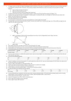
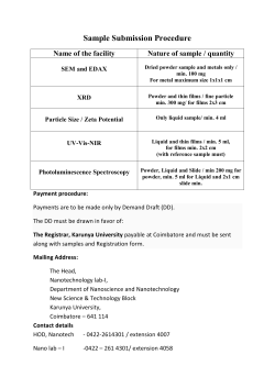


© Copyright 2026