
Digital Image Processing
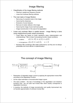
Digital Image Processing 4. Image Enhancement in the Frequency Domain - 3. Filtering 영상처리 연구실 1410685 최홍철 Computer Engineering, Sejong University Filtering Filter concept in the frequency domain 2/19 Filtering Convolution operation of the image and the convolution mask in the spatial domain is processed by multiplication in the frequency domain f ( x, y ) h( x, y ) g ( x, y ) g ( x, y ) h( x, y ) f ( x, y ) F (u , v ) H (u , v ) G (u , v ) G (u , v ) H (u , v ) F (u , v ) 3/19 Filtering Filter appearance in the spatial domain and frequency domain 4/19 Filtering Creation of a filter mask • Convolution mask is used in the spatial domain is converted to a mask in the frequency domain via the DFT • Generate directly in the frequency domain - DFT is not necessary for the mask - It is often used to conceptually simple 5/19 Filtering 1-D filter mask(ideal case) H(f) cutoff frequency f f Low Pass Filter High Pass Filter H(f) H(f) f f Band Pass Filter Band Stop Filter 6/19 Filtering Characteristics of 1-D filter mask • Low pass filter : The low-frequency component in the input image is passed through but the high-frequency component is removed. • High pass filter : The high-frequency component in the input image is passed through but the low-frequency component is removed. • Band pass filter : Passes only a specific frequency component from the input image. • Band stop filter: Removes only a specific frequency component from the input image. • cutoff frequency : The frequency that H(f) value is changed from 1 to 0(or changed to ½) 7/19 Filtering Characteristics of 1-D filter mask frequency sweep signal After the low-pass filter applied After the high-pass filter applied After the band-pass filter applied After the band-stop filter applied 8/19 Filtering 2-D filter and processing result 9/19 Filtering Zone-plate image 10/19 Filtering Zone-plate image • Zero frequency component in the center of the image • The far distance from the center, the frequency component is increased • Used effectively for the purpose of testing the characteristics of the filter • Identifying the display properties of the display device • An expression of zone plate image creation(The origin is center of image) f ( x , y ) 127 . 5 (1 cos( V 11/19 Low-pass filtered image 12/19 x2 H y 2 )) Original image 13/19 High-pass filtered image 14/19 Original image 15/19 Laplacian filtered image 16/19 Filtering Practical filter • Sharp cut-off filter as the ideal is unrealistic • The ringing generated during the implementation of a computer • Most of the filters are a combination of the previous four filters • Low-pass filter : Removing noise, Reduction of image, Compression of image, etc. • High-pass filter : Extracting of edge, etc. • Band-stop/pass filter : Color separation of the NTSC signal • Universal filter used by the image processing - Butterworth filter - Gaussian filter 17/19 Filtering Example of Ideal Low Pass Filter (:ILPF) 18/19 Filtering ILPF and its spatial domain representation 19/19


© Copyright 2026