
Gas Tungsten Arc Welding − GTAW − (40 Hours Course)
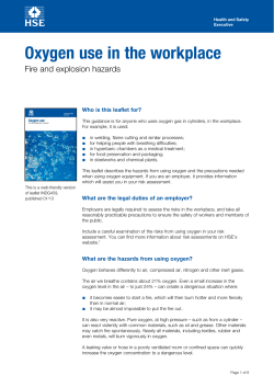
Gas Tungsten Arc Welding − GTAW − (40 Hours Course)
Table of Contents
Gas Tungsten Arc Welding − GTAW − (40 Hours Course)............................................................................1
GENERAL SURVEY...............................................................................................................................1
1. SHORT DISCRIPTION OF THE MOST COMMON WELDING PROCESSES..................................3
1.1 SMAW (Shielded Metal Arc Welding)........................................................................................4
1.2 GMAW (Gas Metal Arc Welding)...............................................................................................4
1.3 GTAW (Gas Tungsten Arc Welding)..........................................................................................6
1.4 Oxy−Acetylene welding..............................................................................................................7
1.5 SAW (Submerged Arc Welding).................................................................................................8
2. FUNDAMENTALS..............................................................................................................................9
2.1 Origin of Gas Tungsten Arc Welding..........................................................................................9
2.2 Advantages of TIG Welding.....................................................................................................10
2.3 Gas Tungsten Arc Welding Process........................................................................................10
2.4 Selecting welding Process.......................................................................................................11
3. PRINCIPLES OF GTAW WELDING.................................................................................................11
3.1 Power Source GTAW...............................................................................................................12
3.2 Setting up Equipment...............................................................................................................13
3.3 Parts Control GTAW................................................................................................................13
4. MAINTENANCE & TROUBLESHOOTING.......................................................................................15
4.1 Routine Maintenance...............................................................................................................15
4.2 Troubleshooting.......................................................................................................................16
5. EQUIPMENT AND MATERIALS......................................................................................................16
5.1 Hose assembly.........................................................................................................................17
5.2 The torch..................................................................................................................................17
5.3 Gas nozzles.............................................................................................................................18
5.4 Shielding− gases......................................................................................................................18
5.5 Electrodes................................................................................................................................20
5.6 Filler rods.................................................................................................................................22
6. WELDING.........................................................................................................................................22
6.1 Welding Preparation.................................................................................................................22
6.2 Striking the Arc.........................................................................................................................23
6.3 Welding Position......................................................................................................................25
6.4 Torch Manipulation...................................................................................................................26
6.5 Basic Welding Joint Positions..................................................................................................27
7. JOINT AND GROOVE DESIGNS.....................................................................................................28
7.1 Joint Design.............................................................................................................................28
7.2 Groove Design.........................................................................................................................34
8. WELD DEFECTS..............................................................................................................................36
8.1 Lack of Penetration..................................................................................................................37
8.2 Incomplete Fusion (Cold Lap)..................................................................................................37
8.3 Porosity....................................................................................................................................38
8.4 Undercutting.............................................................................................................................39
8.5 Cracking...................................................................................................................................39
9. SAFETY AND PRECAUTION...........................................................................................................40
9.1 Personal Safety Equipment (Obligatory)..................................................................................40
9.3 Arc Rays...................................................................................................................................41
9.4 Fumes and Gases....................................................................................................................41
9.5 Fires or Explosion....................................................................................................................42
9.6 Flying Metals can injure eyes...................................................................................................42
9.6 Gas Cylinders...........................................................................................................................42
9.7 Moving Parts............................................................................................................................43
LIST OF NEEDED RESSOURCES FOR "TIG−WELDING" COURSE.................................................44
i
ii
Gas Tungsten Arc Welding − GTAW − (40 Hours Course)
With technical assistance from:
GERMAN DEVELOPMENT SERVICE
August 2000
Dear Reader,
I would like to comment this handout, because otherwise you might get a little confused while studying it.
The most important thing to know is, that this handout is developed for a non−formal Training Center. The
participating government officials and the involved companies were not interested in long−term courses. So, I
had to respect the wish of my project partners for a course with this length and was limited on the most
important subjects.
One or two of the modules are still under construction. Sorry for this.
DED − Development Worker
GENERAL SURVEY
TARGET PARTICIPANTS
• min. 18 years old, at least High School graduate
• College/Vocational graduate or working experience
LENGTH OF COURSE
40 hours
OBJECTIVES
At the end of the training course, the trainee should be able to:
• understand GTAW welding fundamentals and its processes
• identify the major parts of the machine and the different equipment
• set up and shut down the GTAW equipment and know how to maintain the machine
• know and use the proper safety procedures and equipment in GTAW
• learn the different shield gases and the common types of GTAW electrodes and know the
differences between them
• know how to weld mild steel and stainless on square groove butt, lap, T, edge and corner
joint in different positions
• make use of the most common edge preparations and the different weld joint designs
• identify problems and weld defects and know how to correct them
COURSE OUTLINE
1
THEORY (35 %)
HANDS−ON TRAINING (65 %)
• Introduction in GTAW welding
application and principles
• Power sources for GTAW machines
• Types of welding rod
• Various welding positions
• Different manipulation techniques
• Joint and groove designs
• Welding defects
• Safety
• Sharpening tungsten electrode
• Setting up equipment
• Proper handling of GTAW welding
machine
• Preparation of welding specimen
• Establish the arc
• Weld mild steel and stainless with different
groove design and joints
• Safety
METHODOLOGY
• Lecture
• Demonstration
• Return
Demonstration
• Teaching videos
Time Frame Plan of GTAW Welding
(Duration 40 hours)
Topic
Theory
? Methodology
Resources
Needed
Hours
Orientation
• Introducing of
Staff
? Lecture
General
Policies and
Procedures"
0.5
Introduction of
the course
• Origin of gas
tungsten arc
welding
• Advantage of
GTAW − welding
machine
• Overview of the
process of GTAW
welding
? Lecture
Course
handouts
1.0
Principles of
GTAW welding
• Power source
• Setting up GTAW
welding machine
• Parts of the
welding machine
• Parameter setting
? Lecture
Course
handouts
GTAW
welding
machine
1.0
• Check and
maintain The
GTAW welding
machine on a
regular basis for a
trouble free
working operation
? Lecture
Course
handouts
GTAW
welding
machine
1.0
Maintenance and
trouble shooting
of GTAW
welding and
accessories
Hands−on Training
(Practical Sessions)
"Familiarization
Tour" to the
Workshop and the
Office−Building
Hours
Total
Hours
0.5
1.0
(1.0)
1.0
(2.0)
Demonstrate the
operating principles
of GTAW welding
2.0
3.0
(5.0)
2.0
3.0
(8.0)
2.0
3.0
(11.0)
Select parameter
for a given task
Show important
parts of the machine
and its application
Check:
− Cylinder gas
content
− Electrical
connection
− Polarity setting
− Ceramic cap
Grind:
− Tungsten rod
Safety and
health measure
in GTAW
welding
• Know the
required clothing in
GTAW welding
during operation
• Know the hazard
during welding
operation
? Lecture
Course
handouts
Sample of
safety
equipment's
1.0
Show different
personal equipment
and their importance
Demonstrate how
to eliminate hazard
directly at the work
place
1.0
1.0
2
Materials for
GTAW welding
Welding process
• Various types of
shielding gases
used in gas
tungsten arc
• GTAW welding
electrode
according to usage
? Lecture
Course
handouts
Sample
tungsten rod
• Proper procedure
in striking the arc
• Method in striking
the arc
• Welding
procedure
? Lecture
Course
handouts
Sample of
welding
specimen
2.0
(13.0)
Show shielding
gas to be used during
welding process
Familiarize with
the color code of
tungsten rod for a
given work to be
accomplish
1.0
6.0
7.0
(20.0)
16.0
17.0
(37.0)
2.0
3.0
(40.0)
Demonstrate the
welding procedures
Demonstrate the
proper method in
striking the arc
Observe safety
gadget to all trainees
Perform actual
striking the arc one at
a time by the trainees
Perform actual
welding − puddling of
beads
Common weld
joint
Weld defects
Total
• Common joint
design
− Butt joint
− Corner joint
− T − joint
− Lap joint
− Edge joint
• Basic groove
design
− Square groove
− V − groove
− Fillet
? Lecture
Course
handouts
Sample joint
and groove
design
1.0
• Causes and
remedy of weld
defects like:
− Incomplete
penetration
− Incomplete
fusion
− Undercut
− Cracks
? Lecture
Course
handouts
Sample of
welding
specimen
1.0
Prepare and weld
workpiece with
different joint
Practical session
− Pudding of beads
on mild−steel,
stainless steel,
aluminum 1G
− Depositing single
pass in a butt joint
using mild steel,
stainless steel,
aluminum 1G
− Depositing a single
bead in a corner joint
1G using mild steel,
stainless steel,
aluminum
− Others
Examine
specimen weld with
GTAW welding
Analyze welding
defect and correct
them during welding
8.5
1. SHORT DISCRIPTION OF THE MOST COMMON WELDING PROCESSES
3
31.5
40
1.1 SMAW (Shielded Metal Arc Welding)
SMAW is one of the oldest, simplest and most versatile joining processes. The electric arc is generated by
touching the tip of a coated electrode against the workpiece. The electrodes are in the shape of a thin long
stick (stick welding). The heat generated, melts a portion of the tip of the electrode, its coating, and the base
metal in the immediate area of the arc. A weld will be formed the molten metal (a mixture of the workpiece and
the electrode metal) and substances from the coating of the electrode, solidifies in the weld area. The
electrode coating deoxidizes and provides a shielding gas in the weld area to protect it from oxygen and
nitrogen in the environment. Electrodes are available for welding most carbon, low alloy and stainless steels,
some non−ferrous metals, and a wide range of maintenance and repair applications.
Operation:
Manuel
Energy source:
AC or DC usually between 50 A and 400 A
Welding
positions:
All
Cost of
equipment:
Low
Advantages:
Portable and flexible, low cost of equipment
Field of
application:
General construction, shipbuilding, pipelines, maintenance, workpieces from 3−19 mm
thickness − with multiple techniques easily to extend.
1.2 GMAW (Gas Metal Arc Welding)
GMAW was developed in the late 1940's and is also called MIG/MAG Welding. Since then it unfolded into
becoming a major element in industry today. It is suitable for welding a variety of ferrous and nonferrous
metals.
4
The arc continuously melts the wire as it is fed in the weld puddle. The weld area is shielded by a flow of gas
such as argon, helium, carbon dioxide, or gas mixtures. The consumable bare wire is fed automatically
through a nozzle into the weld area. Metal can be transferred into the weld−bead in three ways: Spray,
Globular and Short circuiting. Each way has its own advantages and disadvantages.
The process is rapid, versatile, economical and can easily be automated (continuos welding without electrode
changing).
Operation:
Semiautomatic (Movement of Gun controlled by hand) or automatic
Energy source:
DC
Welding positions:
All
Cost of equipment:
Low to high
Advantages:
Most metals weldable, high welding productivity, excellent weld quality, minimal
distortion.
Field of application:
General construction, general metal fabrication, car body, workpieces from 0.75
mm and 12 mm thickness − with multiple techniques easily to extend.
5
1.3 GTAW (Gas Tungsten Arc Welding)
GTAW also known as TIG welding (Tungsten Inert Gas). The filler metal is supplied from a filler wire and is
similar to the metals to be welded. The tungsten electrode is not consumed in this operation and the shielding
gas is usually argon or helium or a mixture of it. Welding with GTAW can also be done without filler metals, as
in welding close−fit joints.
GTAW is used for a wide variety of metals and applications, particular aluminum, copper, brass, magnesium,
titanium and high alloy metals. It is especially suited for thin metals. In general AC power supply is preferred
for aluminum and magnesium because the cleaning action of AC removes oxides and improves weld quality.
DC power supply is also possible.
The cost of the inert gas makes this process more expensive than SMAW, but it provides welds with very high
quality and surface finish.
Operation:
Manual or automatic
6
Energy source:
AC/DC
Welding
positions:
All
Cost of
equipment:
Medium
Advantages:
Most metals weldable, high quality
Field of
application:
Vessel, tank or boiler fabrication; tool or die repair; aluminium casting; pressure valves
or regulators; pipe fittings; bicycle frames; airplanes
1.4 Oxy−Acetylene welding
Oxy−Acetylene welding is developed in the 1900s and is the most common gas welding process. It uses
acetylene fuel. The proportions of oxygen and acetylene are an important factor. At a ratio of 1:1, the burning
gases get a neutral flame. If the supply of oxygen is lower it becomes a reducing flame. With a greater oxygen
supply it becomes an oxidizing flame.
Filler metals are used to bring additional material to the weld zone during welding. They are available as rods
or wire, coated and uncoated, and are made of metals compatible with those to be welded. Oxyacetylene
welding can be used with most ferrous and nonferrous metals for any thickness of workpieces, but the
relatively low heat input limits the process economically to less than 6 mm. A variety of joints can be produced
by this method. It is portable, versatile and economic for low quantity and simple work.
Welding torch
Leftward welding
7
Basic equipment
Operation:
Manual
Energy source:
Acetylene and Oxygen
Welding positions:
All
Cost of equipment:
Low
Advantages:
Low cost of equipment, portable and flexible, most ferrous and nonferrous metals
weldable
Field of
application:
Maintenance, tube−welding, car body repair
1.5 SAW (Submerged Arc Welding)
SAW, developed in the 1940s, is one of the most important automatic welding processes. The arc and the
whole welding zone are covered by a layer of powder. The complete cover of the molten metal prevents
sparks, spatter, intensive ultraviolet radiation and fumes. The flux, which is part of the powder, acts as a
thermal insulator, allowing deep penetration of heat into the workpiece.
The consumable electrode is a coil of bare round wire (1.5 − 10 mm diameter) and is fed automatically
through a tube (welding gun).
Because the powder is fed by gravity, the SAW process is limited to weld in a flat or horizontal position.
Circular welds can be made on pipes, provided that they are rotated during welding. The unfused powder can
be recovered, treated, and refused.
SAW is used to weld a variety of carbon and alloy steel and stainless steel sheet or plate with a high speed
and productivity. The quality of weld is very high. Typical applications are thick plate welding for shipbuilding
and pressure vessels.
8
Operation:
Automatic
Energy source:
AC/DC
Welding positions:
Flat and horizontal
Cost of equipment:
Medium
Advantages:
High deposition rate, high welding productivity, superior quality weldments
Field of application:
Thick plate welding for shipbuilding and pressure vessels
2. FUNDAMENTALS
2.1 Origin of Gas Tungsten Arc Welding
The Gas Tungsten Arc Welding (GTAW) process is sometimes referred to as TIG, or Heliarc. TIG is short for
Tungsten Inert Gas Welding, and the term Heliarc was used because helium was the first gas used for the
process. The aircraft industry developed the GTAW process for welding magnesium during the late 1930's
and the early 1940's. During that time, helium was the primary shielding gas used, along with DCEP welding
current. These caused many problems that limited application of GTAW welding process. But improve the
process effectiveness and reduced its cost. Before the development of the GTAW process, welding aluminum
and magnesium was difficult. The weld produced was porous and corrosion−prone.
9
2.2 Advantages of TIG Welding
The tungsten inert gas process can be used for welding aluminum, magnesium, stainless steel silicon bronze
titanium, copper and copper alloy, and wide range of different metal thickness in mild steel. Top quality welds
made in the above metal need little, if any, cleaning after welding period. TIG Welding is most often used for
joining aluminum from 1/32 inch to 1/8 inch (0.79 to 3.2 mm) thick. Although heavier sections can be joined by
TIG welding, other processes are usually more economical.
TIG welding is an easy method of joining metals that are considered hard−to−weld, and filler and base metals
can be easily matched. With TIG welding, strip of scrap parent metal may be used for filler metal. Post−weld
machining, grinding, or chipping can usually be eliminated due to the easily controlled weld reinforcement.
The need for flux is eliminated, even on hard to weld metal such as aluminum.
2.3 Gas Tungsten Arc Welding Process
In gas tungsten−arc welding (GTW), formerly known as TIG welding (for tungsten inert gas), the filler metal
supplied from a filler wire (because the tungsten electrode is not consumed in this operation, a constant and
stable arc gap is maintained at a constant current level. The metal is similar to the metals to be welded, and
flux is not used. The shielding gas is usually Argon or Helium, or a mixture of the two. Welding with GTAW is
done without filler metals, as in welding close−fits joints. The power supply is either DC at 200 amps. Or AC at
500 ampere. Depending on the metal to be welded. In general, AC is preferred for aluminum and magnesium
because the cleaning action of AC removes and improves weld quality.
10
2.4 Selecting welding Process
Use table to help select the proper welding process for the type and thickness of metal to be welded. As a
general guideline, use AC GTAW (TIG) for welding aluminum/magnesium; use DCEN for all other metals. Use
DCEP SMAW (stick) for welding most metal, and use DCEN for some stainless steel application.
3. PRINCIPLES OF GTAW WELDING
11
3.1 Power Source GTAW
The TIG welding machine may be either AC or DC. The type of machine for particular TIG weld jobs depends
on the materials to be weld.
All three types of welding current, or polarities, can be used for GTAW welding. Each current has individual
featured that it makes more desirable for specific, conditions or with certain types of metals. The major
difference among the current is in their heat distribution and the presence or degree of arc cleaning.
• Direct Current electrode negative (DCEN), which use to be called direct−current straight
polarity (DCRP) current rates about two−thirds of its welding heat on the work and the
remaining one−third on the tungsten.
• Direct Current electrode positive (DCEP), which used to be called direct−current reverse
polarity (DCRP), concentrate only one−third of the arc heat on the plate and two−third of the
heat on the electrode.
• There are many theories as to why DCEP has a cleaning action the most probable
explanation that the electrons accelerated from the cathode surface lift the oxides that
interfere with their movement. The positive ions accelerated to the metals surface provide
additional energy. In combination, the electrons and ions cause the surface erosion needed to
produce the cleaning. Although this theory is disputed, it is important to note that DCEP
occurs, that it requires argon−rich shield gases and DCEP polarity, and that it can be used to
advantage.
• Alternating Current (AC) concentrates about half of its heat on the work and the other half
on the tungsten. Alternating current is DCEN half of the time DCEP the other half of the time.
The frequency at which the current cycle is the rate at which it makes a full change in the
direction. The current cycles at the rate of 60 times per second the current at its maximum
points A and B the rate gradually decrease until stops at points C and D.
Sine Wave
12
3.2 Setting up Equipment
Parts
Function
1 Remote control
Controlling amperage for GTAW
2 Torch
Housing of tungsten electrode Connect receptacle as shown
3 Work clamp
Where the electron is flowing
4 Cylinder
Where compress necessary gas for welding. Use a chain to secure the cylinder to
wall other stationary support.
5 Cylinder valve
Open valve slightly so gas blow dirt from valve, close valve
6 Regulator/Flow
gauge
Install so face is vertical
7 Flow adjust
Typical flow rate is 20 cfh (cubic feet per hour)
The shielding gas is supplied to the regulator and flowmeter from either cylinder or a manifold system. The
cooling water line in the shop or a circular pump system controlled by a pressure reducer.
3.3 Parts Control GTAW
13
Parts
Function
1 Weld process
switch
Use switch to select weld process. In stick position (down), weld output goes ON and
OFF with power switch. In GTAW (TIG) position (UP), remote control device turns ON
and adjusts weld output of unit as limited by amperage control. Built−in arc starter
comes ON when needed to start or stabilize welding arc. No adjustment needed for
arc starter.
2 Pilot Light
Housing of tungsten electrode Connect receptacle as shown
3 Power Switch
Use switch to turn unit, fan and pilot light ON and OFF flowing
4 Amperage
control
For stick (SMAW), use control to adjust amperage within range selected by the
range/polarity switch.
GTAW Remote
control
For remote amperage control used when TIG (GTAW) welding front panel amperage
controls setting is the maximum amperage percentage available to the remote control
device.
6 Reverse
polarity switch
Use switch to select range and polarity of weld output. For direct current electrode
negative (DCEN), use electrode negative position. For direct current electrode positive
(DCEP), use electrode positive position. For alternating current (AC). Use range
needed appropriate AC low or AC high position.
7 High
temperature
shutdown
Light when unit overheats and shuts down
14
8 Output on
(contactor) light
Light when output (contactor) and unit arc ON.
4. MAINTENANCE & TROUBLESHOOTING
NOTE:
Disconnect always power before maintaining!
4.1 Routine Maintenance
Every 3 month:
Replace unreadable labels
Repair or replace cracked weld cable
Replace O−Ring in Electrode/Gas Output receptacle if cracked
Clean and tighten weld terminals
Repair or replace cracked gas hose
Every 6 month:
15
Blow out or vacuum inside
4.2 Troubleshooting
Trouble
Remedy
No weld output; fan does not run.
Place line disconnect switch in On position (see Section 3−5).
Check and replace line fuse(s), if necessary, or reset circuit breaker
(see Section 3−5).
Check for proper input power connections (see Section 3−5).
No weld output; fan on.
Be sure Range/Polarity switch is not set between positions.
Tighten remote control connection to Remote 14 receptacle.
Check remote control (see remote control Owner's Manual).
Unit overheated, Allow unit to cool (see Section 2−3).
Fan not operating; weld output
available.
Check for and remove anything blocking fan movement.
Have Factory Authorized Service Agent check fan motor.
5. EQUIPMENT AND MATERIALS
16
Typical arrangement of tungsten inert gas welding − note the positions of the welder's hands
5.1 Hose assembly
The hose assembly carries the shielding gas welding current cable and cooling water pipes from the
composite power source to the welding torch. Cooling water is needed where a high current is used e.g. 80%
continuous operation with current operation over 250 amps. The hose assembly carries an additional cable
from the torch control switch back to the power source, which allows the gas, water flow, welding current and
high (HF) supply to be controlled from the torch.
5.2 The torch
Various types of welding torch are available for TIG welding. They may be air−cooled or water−cooled and are
usually fitted to the hose assembly. A remote control switch is fitted on some torches.
17
5.3 Gas nozzles
Ceramic gas−nozzle directs the flow of shielding gas around the electrode, the arc and the molten weld pool.
Standard nozzles are 6.5 mm diameter for air−cooled torches and 10.0 mm diameter for water−cooled
torches. Large sizes and specially shaped nozzles are available for particular applications. Ceramic gas
nozzles are brittle and repeated heating and cooling makes them more fragile. The torch or nozzles must not
be dropped or knocked against other objects. A 'gas lens' may be fitted to some torches when working into
tight corners, e.g. fillet joints, to improve the gas coverage and allow welding to be done with a longer
electrode. The nozzle prevents the correct electrode to workpiece gap being achieved and the electrode must
be extended. The gas lens allows this and at the same time improves gas flow.
Ceramic Nozzle (or Cap)
5.4 Shielding− gases
To prevent weld contamination and electrode deterioration the gas shield must (a) prevent atmospheric
contamination of the weld and (b) not react with molten or solidifying weld metal or the tungsten electrode.
The typical shielding gases used in TIG Welding are:
• Argon − Suitable for most applications
• Helium − Gives better penetration and heat input. This gas is more expensive than argon
and because of this is sometimes used as a mixture of 5% helium and 95% argon for welding
18
stainless steels.
More about gases for GTAW
• Shielding gases are usually supplied in cylinders. These should be used in an upright
position supported in a cylinder stand falling and causing accidents.
• Argon shielding gas is supplied in BLUE cylinders.
• Helium shielding gas is supplied in BROWN cylinders.
• The cylinders are supplied pressurized at 170 bar (2500 lb/in2) and must not be exposed to
direct sunlight, which might cause explosion.
• The moisture content of a gas in a cylinder can rise as the cylinder pressure falls. 'Wet'
shielding gas can contaminate welded joints. To prevent this is to recommend that cylinders
should not be used at pressures below 14 bar (200 lb/in2).
• A cylinder should never be emptied completely because if the pressure is allowed to fall
below 30 lb/in2 the cylinder itself may become contaminated.
• The pressure of the gas delivered to the torch is controlled by a regulator, which reduces the
cylinder pressure to operating pressure.
• A flowmeter is also fitted so that the welder may adjust the rate of flow to keep it constant as
the pressure in the cylinder falls.
• The flowmeter may be combined with an economizer, which shuts off the gas when the
torch is hung on the operating lever.
Regulator and CFH Adjustment A common practice is to start with 12−15 Cubic Feet per Hour
19
Regulator with 2 Gauges
5.5 Electrodes
Electrodes are made from tungsten and contain small percentages of either THORIUM or ZIRCONIUM.
These additions ensure better arc striking ability and stability.
• Thoriated tungsten electrodes should be used for DC welding.
• Zirconiated tungsten electrodes should be used for AC welding, and are particularly suitable
for welding aluminum and its alloys and magnesium and its alloys.
• Tungsten electrodes are identified by color code:
− 1 % Thoriated tungsten electrodes have a BLUE tip.
− 2 % Thoriated tungsten electrodes have a RED tip.
− 1 % Zirconiated tungsten electrodes have a BROWN tip.
20
• Electrodes are supplied in lengths of 150 mm (6 ins.) in diameter ranging from 1.2 mm to 4.8
mm. There is a maximum and minimum current for each diameter.
• At high currents the electrodes become overheated and melts. When this happens the next
larger size should be used.
• At low currents the arc may be unstable and the next smaller size should be fitted.
• The working tip of the electrode should be ground to a point on a silicon−carbide grinding
wheel kept only for that purpose. The grinding marks on the electrodes must run along the
taper and not circumferentially round the tip, otherwise the electric current will flow incorrectly
and the weld will be contaminated by the atmosphere.
For DC welding a "sharp" point is desirable
21
For AC welding a "balled" point is desirable
Note:
The electrode point dimensions above are approximate and not critical.
5.6 Filler rods
Filler rods are specially designed for TIG welding and usually supplied in cut lengths of 1 meter in the
following diameters:
• 1.6 mm
• 2.4 mm
• 3.2 mm
• 4.8 mm
• The compositions of filler rods should be chosen to suit the parent metals being welded.
• Filler rods should be stored in clean dry conditions to prevent deterioration. They should be
free from rust, scale, oil grease and moisture, which would contaminate welds, and be
cleaned with stainless steel wool or smooth aluminum oxide cloth immediately before use.
• After cleaning, filler rods should never be touched with bare hands. Wear clean, flexible soft
leather or fire proofed cotton gloves.
6. WELDING
6.1 Welding Preparation
• Select the correct size of tungsten electrode for the type and amount of current being used.
Welding Current
Amps
AC
DC
Electrode Dia.
mm
Gas flow for electrode protrusions
10 mm
12.5mm
16 mm
19 mm
Nozzle Dia.
mm
40 − 90
2.5
310 l/h
(11ft3/hr)
425 l/h
(15 ft3/hr)
570 l/h
(20
ft3/hr)
680 l/h
(24
ft3/hr)
10
80 − 140
3.25
340 l/h
(12
ft3/hr)
450 l/h
(16 ft3/hr)
570 l/h
(20
ft3/hr)
680 l/h
(24
ft3/hr)
10/12.5
100 − 195
4.0
400 l/h
(14
ft3/hr)
510 l/h
(18 ft3/hr)
620 l/h
(22
ft3/hr)
735 l/h
(20
ft3/hr)
12.5/16
180 − 275
4.8
450 l/h
(16
ft3/hr)
570 l/h
(20 ft3/hr)
710 l/h
(25
ft3/hr)
−
−
16
40 − 240
2.5
340 l/h
(12ft3/hr)
370 l/h
(13 ft3/hr)
425 l/h
(15
480 l/h
(17
10
22
ft3/hr)
ft3/hr)
200 − 300
3.25
370 l/h
(13
ft3/hr)
425 l/h
(15 ft3/hr)
510 l/h
(20
ft3/hr)
570 l/h
(20
ft3/hr)
12.5
300 − 400
4.0
425 l/h
(15
ft3.hr)
570 l/h
(20 ft3/hr)
710 l/h
(25
ft3/hr)
−
−
16
250 − 350
6.25
570 l/h
(20
ft3/hr)
710 l/h
(25 ft3/hr)
790 l/h
(28
ft3/hr)
−
−
16
The above table gives the relationship between welding current, electrode diameter, gas flow and nozzle
diameter.
Note:
Use this table to select gas flow rates to obtain optimum gas shielding and
economy of use.
• Taper the tip of the electrode by grinding
• Select a collet matching the diameter of the tungsten electrode to be used and fit the
electrode into the collet.
• Fit the collet and electrode into the head of the welding torch and position, approximately,
the electrode protrusion by tightening the torch cap.
• Select an appropriate ceramic nozzle and screw it on the head of the welding torch. Finally
slacken the torch cap and adjust the position of the electrode to give a protrusion of approx.
10 mm.
Note:
The choice of nozzle will depend on the amount of current being used and the length of
electrode protrusi electrode protrusion required.
The shape of the nozzle will depend on the dimensions of the joint to be welded.
Accessibility into the joint and the visibility required at the arc.
• Switch on the mains power supply
• Set the current control at the power source to suit the welding conditions
• Open the valve on the Argon gas cylinder slowly and adjust the flow−meter control valve.
Keep the torch away from the workpiece to avoid stray arcing.
6.2 Striking the Arc
Steps:
• Set up the plate in the flat position on a worktable. Ensure that there is electrical contact
between the workbench and the plate.
• Clamp an earth lead to the workpiece and a close positive earth.
• Thoroughly clean the surface of the plate to remove any scale, oil or grease
• Clean the filler rod by rubbing lightly with stainless steel wool or aluminum oxide to remove
any impurities on its surface.
23
Before cleaning, wear clean soft leather or fire proofed cotton gloves to avoid
contaminating the filler rod.
• Switch on the power source.
• Grip the welding torch lightly in the hand with the thumb on the torch switch.
Gripping tightly will cause arm shake and loss of control.
• Lower the torch until the tip of the electrode is approximately 12 mm above the point where
the arc is to be struck and about 12 mm from the end of the plate.
• Lower the head screen to cover the face and press the foot control switch. A series of
sparks will jump across the arc gap and the welding arc form.
• Bring the conical tip of the arc down to the surface of the plate. Hold the arc steady to allow
a molten weld pool to form as the heat of the arc melts the plate.
• Once the size of the weld pool has been established, move the tip of the arc to the back of
the weld pool to allow filler metal to be added.
• Advance the filler rod towards the molten pool at the recommended angle and dip the tip
into the front edge of the molten pool.
− Listen to check that the gas is flowing freely
− Use the correct torch angle as shown.
− Make sure that the tip of the electrode does not dip into the molten pool and cause
tungsten contamination of the weld
− Maintain the correct torch angle.
• When sufficient filler metal has been melted off the rod withdraw the rod from the molten
pool.
• Move the torch to the front of the molten pool to fuse the added filler metal with the parent
metal.
• Continue welding in this manner, using the recommended angles for torch and filler rod, for
approximately 75 mm.
• Pause at the end of the weld run and position the tip of the arc over the center of the weld
pool.
• When the arc has been extinguished keep the tip of the torch over the crater for a few
seconds to allow the weld to cool slightly as the automatic post weld gas purging takes place.
• Switch off the power source and place the torch on its stand.
• Clean the deposited weld by wire brushing with a stainless steel wire brush to prevent
contamination of the weld deposit.
− Take care not to lift the filler rod tip out of the blanket of shielding gas as the hot tip cools.
The gas prevents weld contamination from the atmosphere.
− Adjust the speed of travel and rate of filler metal feed to produce a weld of uniform shape
and appearance.
− Pressing the torch switch automatically and gradually decreases the welding current.
This eliminates cavities in the weld crater where cracking may occur
24
• Examine the weld for quality and appearance. The deposit should be dull to bright silvery
Grey in color and smooth in texture.
Should the surface of the deposit appear dark and coarse in texture, check that the shielding
gas flow rate is sufficient and that there are no leaks in the gas pipeline.
6.3 Welding Position
25
Weld Positions and Joints
6.4 Torch Manipulation
Moving Torch without Filler Rod
26
Moving Torch with Filler Rod
6.5 Basic Welding Joint Positions
Butt Weld And Stringer Bead
27
"T" Joint
Lap Joint
7. JOINT AND GROOVE DESIGNS
7.1 Joint Design
A weld joint is the term used for the location where two or more pieces of metal are to be, or have been,
welded together. In order to obtain a good weld and economical use of filler metal, joint design must be
considered in any type of weldment. This will depend upon several factors including material type, thickness,
joint configuration, strength required, etc.
It is quite possible that a welder would have little to do with how a particular joint is designed.
However, a good welder should be familiar enough with these joint designs to carry out a welding job.
A proper joint design will provide the required strength that codes and specifications designate. The correct
joint design will then need the highest quality weld made at the most economical cost. The joint design
selected will, of course, dictate what type of weld is to be made.
Of the five basic joint designs, the "Butt" and "T" are the most commonly welded.
28
A few considerations for joint design must be made that are particular for GTAW. Naturally the weld joint must
be accessible to the GTAW nozzle, making it possible for proper nozzle movements. Weld joints also should
not be too narrow, so as to restrict access of the nozzle. (In some cases, narrower gun nozzles will help.)
Also, the nozzle−to−work distance cannot be too great in the weld joint so as to cause poor root penetration
and poor shielding gas coverage.
7.1.1 Butt Joints
A butt joint occurs when the surfaces of the members to be welded are in the same plane with their edges
meeting. Butt joints are often used to join such things as, boilers, tanks, plate, pipe, tubing or any application
where a smooth weld face is called for. They generally require more welding skill than do some of the other
joints. Butt joints have very good mechanical strength if properly made. They can be expensive joints to make,
however, since many times some joint preparation must be done. Distortion and residual stresses can be
problems with butt joints. Butt joints can be designed in various ways. The edges can be square or beveled
grooved. Edges may be held tight together or a small gap known as a root opening may be left between the
edges.
To keep the two separate, the picture below shows the difference between the groove face and the root
face. In this example the root face is 1/8". The groove face means the surface of the metal in the groove
including the root face. The main purpose of the various grooves and root openings is to allow proper
penetration and depth of fusion.
29
For example, if material thickness is less than approximately 1/8 inch (3,2 mm) thick, square edges can be
used with a short−circuiting process. (Aluminum would probably require a small or no root opening.) However,
plate thickness 1/8 inch and greater generally require single or double V−grooves and root openings for
proper penetration and depth of fusion. Joint preparation before welding will depend upon the joint design and
the equipment available to do the edge preparation.
The oxy−fuel torch is often used to cut a bevel edge or square edges on steel plates. Electric grinder will be
used for stainless and aluminum.
7.1.2 T−Joints
A T−joint occurs when the surfaces of two members come together at right angles (90 degrees) and take the
shape of a "T". On this particular type of joint, a fillet weld is usually made. T−joints offer good mechanical
strength, especially when welded from both sides. They generally require little or no joint preparation and are
easily welded when the correct parameters are used. The edges of the T−joint may be left square or they may
prepare them by machining or grinding.
30
7.1.3 Edge Joints
Edge joints are often used when the members to be welded will not be subjected to any great stresses. Edge
joints are not recommended where impact or any other great stresses may occur to one or both of the welded
members. An edge joint occurs where the edges of parallel or nearly parallel members meet and are joined by
a weld. The main purpose of these grooves is to allow proper penetration or depth of fusion.
7.1.4 Lap Joints
Another joint design used in the welding industry is the lap joint. As can be seen in the picture below, lap joints
occur when the surfaces of joined members overlap one another. A lap joint has good mechanical properties,
especially when welded on both sides. The weld form used on a lap joint is generally a fillet weld. The degree
of overlap of the members is generally determined by the thickness of plate. In other words, the thicker the
plate, the more overlap is needed.
31
7.1.5 Corner Joints
When members to be welded come together at weld is usually made about 90 degrees and take shape of an
"L", they are said to form a corner joint. These joints are quite easily assembled and require little if any joint
preparation. After welding, the welds are generally finished, that is, ground smooth to present a smooth
attractive appearance. When this is the case, all effort by the welder should be made to prevent weld defects.
There are two main types of corner joints, open corner and closed corner. On lighter gauge material, it may
J−Groove be necessary to increase travel speed somewhat, especially on open corner joints where excessive
melt through is a possibility.
32
7.1.6 Fillet Welds
Fillet welds are approximately triangular in cross sectional shape and are made on members whose surfaces
or edges are approximately 90 degrees to each other. Fillet welds can be as strong, or stronger than the base
metal if the weld is the correct size and proper welding techniques are used. When discussing the size of the
fillet weld, it is generally the length of the leg of the weld that is being referred to. The figure below shows a
fillet weld and the terms associated with it. The general rule for fillet weld size is: the leg should be the same
size as the thickness of the metals. If 1/2 inch, thick plate is being welded, a 1/2−inch leg fillet is needed to
properly join the members. The old saying, "if a little is good, a lot is better", may be true in some cases but
not with fillet welds.
Fillet Weld Terms
Consider again the 1/2−inch thick plate. If a lot of weld would be better, think of 3/4−inch legs on the fillet. This
would result in what is termed over−welding. These wastes weld metal, the welder's time, causes more
distortion and may even weaken the structure because of residual stress. The pictures below are showing
correct and incorrect fillet welds.
A correctly fillet weld. Leg equals thickness of plate
Over welded. Legs of weld too large for thickness of plate
Under welded. Need larger legs on fillet
33
And consider another factor in correct fillet weld size − when metals of different thickness are to be joined.
When welding a 1/2 inch thick plate onto a 1 inch thick plate in the form of a T−joint, the rule for fillet weld size
is: Size of fillet weld leg should equal the thickness of the metal being welded. Since there are two different
thicknesses, the best results will be obtained by making an unequal leg fillet weld. A weldment is not
stronger than its weakest point.
Unequal leg fillet (joint failure)
Equal leg 1" fillet (wasted weld metal, time and extra heat)
Equal leg 1/2" fillet (less time, less weld metal, less heat input. Just as strong as figure B
7.2 Groove Design
34
Common Groove Designs
7.2.1 Square−Groove
A square−groove weld can be made with either a closed or an open groove.
Usually if the base metal is thin (such as thin sheet metal gauge thicknesses), a square groove weld can be
made. In the base metal thickness range of 1/8" to 1/4", it is good to weld both sides of an
opensquare−groove− weld to provide proper penetration into the groove. Usually,
open−square−groove−welds will not be made with groove openings of more than about 5/32".
7.2.2 V−Groove
Although they can require careful preparation, V−groove weld designs are quite popular. They can provide
excellent weld quality if properly completed. V−groove weld designs may or may not use permanent or
temporary backups, depending upon the joint design and type of joint penetration needed. Usually if backups
are used, root openings can be somewhat wider.
V−groove welds are usually made on medium to thicker metals, and are used quite often for pipe welding.
The groove angle for a groove weld must be large enough for the welding gun to fit into the groove. This
depends upon metal thickness, desired electrode extension and gun nozzle size. Usually V−groove welds are
made on material over 1/8" to 1/4" in thickness. As the metal thickness increases, a root face can help provide
good penetration.
The groove angle for GTAW groove welds is usually smaller than the Groove angles needed for SMAW.
This can be a cost saver. As mentioned earlier, tapered nozzles are sometimes used to provide access into
smaller grooves. A typical V−groove angle could be 60 degrees or even less, compared to 60 to 75 degrees
for SMAW.
35
V−groove welds are often made on material up to about 5/8" thicknesses, while double V−groove welds are
normally made on thicker materials up to roughly 2" in thickness. Double V−groove welds on thicker materials
can use less deposited weld metal and limit distortion in the weld, especially if a small root face of about 1/8"
is used on each member. Usually the weld passes on such a joint would be made alternating from one side of
the joint to the other. This can help to avoid distortion.
7.2.3 Bevel−Groove
The bevel−groove welds also require preparation. But in this case only one member need to be beveled. The
single bevel−groove can be used on material up to about 5/8", while double bevel−grooves are used on
thicker material up to about 1". In most cases, up to 1/8" root openings are used on single and double bevels.
7.2.4 U− and J−Grooves
On thicker materials, U− or J−grooves can provide for good penetration. This is without using as much
deposited weld metal as a V−groove or bevel−groove joint design. This is because with thicker materials the
U− and J−grooves can be used with a smaller groove angle and still maintains proper fusion. A normal groove
angle for either a U or J−groove is about 20 to 25 degrees. This would also apply to the double U− and double
J−grooves.
Usually no root openings are used for these grooves on thicker materials. Material thicknesses can range
from 1/2" and thicker.
One disadvantage of U− and J−groove designs is the preparation of the base metal. Special gauging or other
preparation is needed for the J type design. V− or bevel−grooves are easier to prepare.
8. WELD DEFECTS
Before describing specifics, it is important to point out the difference between a weld defect and a weld
discontinuity. Every weld can be said to have some discontinuities, since there really is no perfect weld.
Some welding instructors, specification books, or codes may allow for a certain amount of discontinuities
without calling the weld defective. There is usually a certain point at which the weld will be considered
defective. A defective weld would be rejected, for example, for a welder's qualifying test. A defective weld in a
manufacturing situation would have to be ground out and replaced, or the entire base metal structure would
be rejected.
It is important that some discontinuities in a weld are allowable. When one or more discontinuities cause a
weld to fail a particular weld test, this type of discontinuity would then be termed a defect. Acceptable limits
can change due to many factors. If the weld requirements are very strict, acceptable limits for the number and
size of discontinuities may be quite low.
It is quite easy to encounter many kinds of discontinuities and defects when first learning the GTAW process.
Discontinuities and defects can be caused by many factors, including:
• Improper welding techniques
• Improper shielding gas
• Improperly prepared or contaminated base metal
• Dirty or contaminated electrode
• Improper secondary circuit
• Equipment problems
The most common weld defects are:
• Lack of Penetration
• Incomplete Fusion
• Porosity
• Undercutting
• Cracking
36
Remember: A good weld is not stronger than its weakest point.
8.1 Lack of Penetration
When molten weld metal has not sufficiently penetrated into the base metal, a weld defect can occur, called
lack of penetration. Full strength of a joint is not possible if the penetration is not adequate. Lack of
penetration can be caused by any one of a number of factors.
Controlled penetration is also difficult to achieve when poor fit−up of the base members occurs.
8.2 Incomplete Fusion (Cold Lap)
How well the base metal and weld metal are joined together is termed fusion. Fusion is important if full
strength of a joint is to be achieved.
Incomplete fusion means that at some point in a weld, the base metal and weld metal have not been joined
properly. This could occur at any point in the weld.
Possible causes for incomplete fusion or cold lap:
• Failure to raise the temperature of the weld area to the correct level
• Failure to remove large amounts of mill scale, oxides, or any other foreign materials present
on the base metal. These materials could hinder the fusing of the weld metal to the base
metal.
• Improper joint design basically refers to the size of the groove angle and root openings on a
butt joint. Should these angles or openings be too small for proper electrode extension and
gas shielding, incomplete fusion and possible other defects can occur.
37
8.3 Porosity
Porosity is one of the more common weld defects. It can occur at the surface or face of the weld. Or, porosity
can occur inside the weld, where it is difficult to detect. Subsurface porosity cannot be seen with the naked
eye but can be detected with various means of testing. Gases being trapped in the solidifying weld cause
porosity. Put another way, the metal is freezing before the gas has a chance to fully escape from the weld.
Porosity looks like many small holes in a weld − much like the wormholes in a piece of wood. The gas pockets
or pores are usually round in shape and can vary in size.
Primary sources for porosity:
• Moisture
• Dirty wire or base metal
Moisture:
The primary cause of porosity is moisture. This moisture is heated by the welding arc and molten metal, and
becomes a gas. Hot metal will absorb some of this gas but the rest of it, being lighter than the metal, floats to
the surface and out into the air. The problem comes from the gas that is absorbed by the molten metal.
Hot metal will absorb more gas than cold metal. Therefore, as the weld bead begins to cool, the gas can no
longer stay in the cooling metal and must come out. As the metal cools it becomes less liquid, and at some
point the escaping gas can no longer float through the hardening metal. The gas is then trapped and causes
porosity.
Sources for moisture:
• Contaminated, or wet base metal
• Excessive humidity or any moisture in the air
Dirty filler wire or base metal:
Filler containing any foreign matter can cause porosity. Because of this, any oils or other foreign materials on
or worked into the electrode wire can amount to a substantial amount of material in the resulting weld. Filler
wire should thus be kept as clean as possible. If the metal has excess oil, scale, rust, etc., porosity could
easily result in the weld.
38
8.4 Undercutting
Undercutting is a defect that appears as a groove in the parent metal directly along the edges of the weld.
This type of defect is most commonly caused by improper welding parameters particularly the travel speed
and arc voltage.
When the travel speed is too high, the weld bead will be very peaked because of its extremely fast
solidification. The forces of surface tension have drawn the molten metal along the edges of the weld bead
and piled it up along the center. Melted portions of the base plate are affected in the same way. The undercut
groove is where melted base material has been drawn into the weld and not allowed to wet back properly
because of the rapid solidification. Decreasing the arc travel speed will gradually reduce the size of the
undercut and eventually eliminate it. When only small or intermittent undercuts are present, raising the arc
voltage or using a leading torch angle are also corrective actions. In both cases, the weld bead will become
flatter.
8.5 Cracking
When a metal is put under stress it can crack. Cracks can occur on top of a weld bead, within the weld, or in
the base metal.
With the GTAW process and proper welding procedures, weld cracks are held to a minimum.
Because GTAW filler wires have no flux coating to attract moisture, they are by nature low hydrogen in
content. They can help avoid cracking in the weld and heat−affected zone if kept clean and dry. The filler wire
must be free of moisture while being used and when stored.
A cracking defect is very often associated with the welding of aluminum. A crack can easily occur on
aluminum due to metal contraction as the weld pool cools, while the base metal remains hot. This is especially
possible in the weld crater at the end of a weld. Therefore, the crater should proper strength and weld size.
Cracks may be more numerous with aluminum but they may also occur in stainless steel and steel and
galvanized materials. For both stainless steel cracks may occur if excess heat input is used for the particular
thickness of material being welded. Also, steels with high carbon content (over 30 %) are likely to crack due to
their hardness.
39
9. SAFETY AND PRECAUTION
As in any welding process, Gas Tungsten Arc Welding (GTAW) safety precautions are very important. All
information relating to the safe operation of the welding equipment and the welding process must be fully
understood before attempting to begin work. A careless welder who does not observe some simple rules can
cause a dangerous situation for everyone in the area. The process of arc welding creates several hazards,
which must be guarded against. Useful safety information can be found in the Owner's Manual that comes
with each item of welding equipment.
GTAW is an electrical welding process. Therefore, electrical energy is required from a welding machine. If the
welding machine has the characteristics of a transformer or a motor−generator design, electrical energy is
required as primary power to operate it. The welding machine must be installed according to the
manufacturer's recommendation and in accordance with the National Electrical Code and local code
requirements.
9.1 Personal Safety Equipment (Obligatory)
9.2 Electrical Shock
Welders must be concerned about the possibility of electrical shock. It should be remembered that electricity
would always take the path of least resistance. If there is a proper secondary circuit, the current will follow
that path. However, if there are poor connections, bare spots on cables, or wet conditions, the possibility of
electrical shock does exist.
A welder should never weld while standing in water. If wet working conditions exist, certain measures should
be taken. Such measures include standing on a dry board or a dry rubber mat when welding. Likewise, the
welding equipment should not be placed in water. In addition, gloves and shoes must be kept dry. Even a
person's perspiration can lower the body's resistance to electrical shock.
Important Rules:
40
• Do not touch live electrical parts
• Wear dry, hole−free insulating gloves and body protection
• Insulate yourself from work and ground using dry insulating mats or covers
• Disconnect input power or stop engine before installing or servicing this equipment
• Properly install and ground the equipment including the welding table
• When making input connections, attach proper grounding conductor first
• Turn off all equipment when not in use
• Do not use worn, damaged, undersized, or poorly spliced cables
• Do not touch electrode if in contact with the work or ground
• Use only well maintained equipment. Repair or replace damaged parts at once
• Keep all panels and covers securely in place
9.3 Arc Rays
Several possible hazards exist due to the electric arc, infrared and ultraviolet rays. The light and rays can
produce a burn similar to sunburn, The arc rays, however, are more stronger than sunburn since the welder is
so close to the source. These rays can quickly burn any exposed skin.
Rules:
• Keep your head out of the fumes. Do not breathe the fumes.
• If inside, ventilate the area and/or use exhaust at the arc to remove welding fumes and
gases
9.4 Fumes and Gases
Fumes and gases can be hazardous to your health.
Rules:
• Wear a welding helmet fitted with a proper shade of filter to protect your face and eyes when
welding or watching.
41
• Use protective screens or barriers to protect others from flash and glare; warn others not to
watch the arc.
• Wear approved safety glasses. Side shields recommended.
9.5 Fires or Explosion
Welding can cause fire or explosion
Rules:
• Protect yourself and others from flying sparks and hot metal
• Do not weld where flying sparks can strike flammable material
• Remove all flammables near of the welding arc
• A fire extinguisher should all the time available
9.6 Flying Metals can injure eyes
Rules:
• Welding, chipping, wire brushing, and grinding can cause spark and flying metal. As weld
cool down they can throw slag.
• Wear approved safety face shield with side protection
9.6 Gas Cylinders
Regardless of the content, pressurized cylinders must at all times be handled with great care. Shielding gases
such as carbon dioxide, argon and helium are nonflammable and nonexplosive. But for instant a broken off
valve, however, will release extremely high pressures, which could cause the cylinder to be hurled about at
dangerously high speeds. Another way of thinking about this pressure is to compare a cylinder to a balloon. If
a balloon is blown up and then released, the jet force of air escaping causes the balloon to fly about quite
42
rapidly. The same would be true if a cylinder valve would break off. Only now, the weight of the cylinder and
the extremely high pressure could easily cause a very damaging and possibly fatal accident. Cylinders should
be securely fastened at all times. Chains are usually used to secure a cylinder to a wall or cylinder cart. When
moving or storing a cylinder, a threaded protector cap must be fastened to the top of the cylinder. This
protects the valve system should it be bumped or the cylinder dropped. It is accepted procedure to roll a
cylinder in the upright position when moving the cylinder.
It is also very important to keep excess heat of any kind away from cylinders. When a cylinder is exposed to
too much heat, the pressure inside the cylinder will increase.
Rules:
• Keep cylinders away from any welding or other electrical circuits
• Never allow a welding electrode to touch any cylinder
• Install and secure cylinders in an upright position by chaining them to a stationary support or
equipment cylinder rack to prevent falling or tipping
9.7 Moving Parts
Moving parts can cause injury.
Rules:
• Keep yourself away from pinch points such as drive rolls
• Keep all doors, panels, covers, and guards of the welding machine closed and securely in
place
43
LIST OF NEEDED RESSOURCES FOR "TIG−WELDING" COURSE
Need to
Order/Replace/Organize
Resource
Checked Unit Qty for 1
Trainee
Qty for 4
Trainees
Unit Qty Unit
Price
Amount
Teaching Aids
Forms
Consumables and
Parts for Exercises
44


© Copyright 2026