
Aircraft Welding Chapter 5 Introduction
Chapter 5
Aircraft Welding
Introduction
Welding can be traced back to the Bronze Age, but it was
not until the 19th century that welding as we know it today
was invented. Some of the first successful commercially
manufactured aircraft were constructed from welded steel
tube frames.
As the technology and manufacturing processes evolved
in the aircraft and aerospace industry, lighter metals, such
as aluminum, magnesium, and titanium, were used in their
construction. New processes and methods of welding these
metals were developed. This chapter provides some of the
basic information needed to understand and initiate the
various welding methods and processes.
5-1
Traditionally, welding is defined as a process that joins metal
by melting or hammering the work pieces until they are
united together. With the right equipment and instruction,
almost anyone with some basic mechanical skill, dexterity,
and practice can learn to weld.
There are three general types of welding: gas, electric arc,
and electric resistance. Each type of welding has several
variations, some of which are used in the construction of
aircraft. Additionally, there are some new welding processes
that have been developed in recent years that are highlighted
for the purpose of information.
This chapter addresses the welding equipment, methods,
and various techniques used during the repair of aircraft and
fabrication of component parts, including the processes of
brazing and soldering of various metals.
Oxygen pressure regulator
Acetylene pressure regulator
0
300
0
100
200
300
100
200
Oxygen cylinder
0
100
200
0
300
300
100
200
Acetylene cylinder
Torch
Types of Welding
Gas Welding
Gas welding is accomplished by heating the ends or edges
of metal parts to a molten state with a high temperature
flame. The oxy-acetylene flame, with a temperature of
approximately 6,300 °Fahrenheit (F), is produced with a torch
burning acetylene and mixing it with pure oxygen. Hydrogen
may be used in place of acetylene for aluminum welding, but
the heat output is reduced to about 4,800 °F. Gas welding was
the method most commonly used in production on aircraft
materials under 3⁄16‑inch in thickness until the mid 1950s,
when it was replaced by electric welding for economic (not
engineering) reasons. Gas welding continues to be a very
popular and proven method for repair operations.
Nearly all gas welding in aircraft fabrication is performed
with oxy-acetylene welding equipment consisting of:
•
Two cylinders, acetylene and oxygen.
•
Acetylene and oxygen pressure regulators and cylinder
pressure gauges.
•
Two lengths of colored hose (red for acetylene and
green for oxygen) with adapter connections for the
regulators and torch.
•
A welding torch with an internal mixing head, various
size tips, and hose connections.
•
Welding goggles fitted with appropriate colored lenses.
•
A flint or spark lighter.
•
Special wrench for acetylene tank valve if needed.
•
An appropriately-rated fire extinguisher.
The equipment may be permanently installed in a shop, but
most welding outfits are of the portable type. [Figure 5-1]
5-2
Figure 5-1. Portable oxy-acetylene welding outfit.
Electric Arc Welding
Electric arc welding is used extensively by the aircraft industry
in both the manufacture and repair of aircraft. It can be used
satisfactorily to join all weldable metals, provided that the
proper processes and materials are used. The four types of
electric arc welding are addressed in the following paragraphs.
Shielded Metal Arc Welding (SMAW)
Shielded metal arc welding (SMAW) is the most common type
of welding and is usually referred to as “stick” welding. The
equipment consists of a metal wire rod coated with a welding
flux that is clamped in an electrode holder that is connected by a
heavy electrical cable to a low voltage and high current in either
alternating current (AC) or direct current (DC), depending on
the type of welding being done. An arc is struck between the
rod and the work and produces heat in excess of 10,000 °F,
which melts both the material and the rod. The welding circuit
consists of a welding machine, two leads, an electrode holder,
an electrode, and the work to be welded. [Figure 5-2]
When the electrode is touched to the metal to be welded,
the circuit is complete and the current flows. The electrode
is then withdrawn from the metal approximately 1⁄4-inch to
form an air gap between the metal and the electrode. If the
correct gap is maintained, the current bridges the gap to form
a sustained electric spark called the arc. This action melts the
electrode and the coating of flux.
As the flux melts, it releases an inert gas that shields the
molten puddle from oxygen in the air to prevent oxidation.
The molten flux covers the weld and hardens to an airtight
Welding cable connector
Generator
Welding cable
Electrode holder
Ground cable
Gro
Ground cable connector
Metal being welded
Figure 5-2. Typical arc welding circuit.
slag that protects the weld bead as it cools. Some aircraft
manufacturers, such as Stinson, used this process for the
welding of 4130 steel fuselage structures. This was followed
by heat treatment in an oven to stress relieve and normalize
the structure. Shown in Figure 5-3 is a typical arc welding
machine with cables, ground clamp, and electrode holder.
torch and the work, and the arc produces the intense heat
needed to melt the work and the electrode. [Figure 5-4]
Low-voltage high-current DC is typically used with GMAW
welding. Figure 5-5 shows the equipment required for a
typical MIG welding setup.
This method of welding can be used for large volume
manufacturing and production work; it is not well suited to
repair work because weld quality cannot be easily determined
without destructive testing. Figure 5-6 depicts a typical power
source used for MIG welding.
Gas Tungsten Arc Welding (GTAW)
Gas tungsten arc welding (GTAW) is a method of electric arc
welding that fills most of the needs in aircraft maintenance
and repair when proper procedures and materials are used. It
is the preferred method to use on stainless steel, magnesium,
and most forms of thick aluminum. It is more commonly
known as Tungsten Inert Gas (TIG) welding and by the trade
names of Heliarc or Heliweld. These names were derived
from the inert helium gas that was originally used.
Figure 5-3. Stick welder–Shielded Metal Arc Welder (SMAW) .
Gas Metal Arc Welding (GMAW)
Gas metal arc welding (GMAW) was formerly called metal
inert gas (MIG) welding. It is an improvement over stick
welding because an uncoated wire electrode is fed into and
through the torch and an inert gas, such as argon, helium,
or carbon dioxide, flows out around the wire to protect the
puddle from oxygen. The power supply is connected to the
The first two methods of electric arc welding that were
addressed used a consumable electrode that produced the
filler for the weld. In TIG welding, the electrode is a tungsten
rod that forms the path for the high amperage arc between it
and the work to melt the metal at over 5,400 °F. The electrode
is not consumed and used as filler so a filler rod is manually
fed into the molten puddle in almost the same manner as
when using an oxy-acetylene torch. A stream of inert gas,
such as argon or helium, flows out around the electrode and
envelopes the arc thereby preventing the formation of oxides
in the molten puddle. [Figure 5-7]
5-3
Shielding gas
Nozzle
Molten weld metal
Consumable electrode
(machine fed)
Solidified weld metal
Figure 5-4. Metal inert gas (MIG) welding process.
Shielding gas
Regulator with flowmeter
Wire reel
Work
Wire drive
Power source
Controls for governing
wire drive current, gas flow,
and cooling water, if used.
Contactor
Figure 5-5. MIG welding equipment.
5-4
Gas supply
Wire drive may be
located in welding gun
handle or at wire reel.
The versatility of a TIG welder is increased by the choice of
the power supply being used. DC of either polarity or AC
may be used. [Figure 5-8]
•
Either select the welder setting to DC straight polarity
(the work being the positive and the torch being
negative) when welding mild steel, stainless steel,
and titanium; or
•
Select AC for welding aluminum and magnesium.
Figure 5-9 is a typical power source for TIG welding along
with a torch, foot operated current control, regulator for inert
gas, and assorted power cables.
Electric Resistance Welding
Electric resistance welding, either spot welding or seam
welding, is typically used to join thin sheet metal components
during the manufacturing process.
Figure 5-6. MIG welder–gas metal arc welder (GMAW).
Tungsten electrode
Welding torch
Shielding gas
Molten weld metal
Arc
Solidified weld metal
Filler wire (hand fed)
Figure 5-7. Tungsten inert gas (TIG) welding process.
Figure 5-9. TIG welder–gas tungsten arc welder (GTAW).
Electrode holder
Regulator with flowmeter
Filler metal held manually if used
Tungsten electrode
Electrical conductor
Insulating sheath
Gas passages
Power source
Work
Gas supply
Shielding gas
Figure 5-8. Typical setup for TIG welding.
5-5
Spot Welding
Two copper electrodes are held in the jaws of the spot welding
machine, and the material to be welded is clamped between
them. Pressure is applied to hold the electrodes tightly
together and electrical current flows through the electrodes
and the material. The resistance of the material being welded
is so much higher than that of the copper electrodes that
enough heat is generated to melt the metal. The pressure on
the electrodes forces the molten spots in the two pieces of
metal to unite, and this pressure is held after the current stops
flowing long enough for the metal to solidify. The amount of
current, pressure, and dwell time are all carefully controlled
and matched to the type of material and the thickness to
produce the correct spot welds. [Figure 5-10]
In the plasma welding torch, a nonconsumable tungsten
electrode is located within a fine-bore copper nozzle. A
pilot arc is initiated between the torch electrode and nozzle
tip. This arc is then transferred to the metal being welded.
[Figure 5-11]
−
Tungsten ele
T
electrode
Arc core
Outer cool
cool sheath
she
Outer
Inner hot sheath
she
eath
+
Figure 5-11. The plasma welding process.
By forcing the plasma gas and arc through a constricted
orifice, the torch delivers a high concentration of heat to a
small area. The plasma process produces exceptionally high
quality welds. [Figure 5-12.]
Figure 5-10. Spot welding thin sheet metal.
Seam Welding
Rather than having to release the electrodes and move the
material to form a series of spot welds, a seam-welding machine
is used to manufacture fuel tanks and other components where
a continuous weld is needed. Two copper wheels replace
the bar-shaped electrodes. The metal to be welded is moved
between them, and electric pulses create spots of molten metal
that overlap to form the continuous seam.
Plasma Arc Welding (PAW)
Plasma arc welding (PAW) was developed in 1964 as a
method of bringing better control to the arc welding process.
PAW provides an advanced level of control and accuracy
using automated equipment to produce high quality welds
in miniature and precision applications. Furthermore, PAW
is equally suited to manual operation and can be performed
by a person using skills similar to those for GTAW.
5-6
Figure 5-12. Plasma arc.
Plasma gas is normally argon. The torch also uses a secondary
gas, such as argon/helium or argon/nitrogen, that assists in
shielding the molten weld puddle and minimizing oxidation
of the weld.
Like GTAW, the PAW process can be used to weld most
commercial metals, and it can be used for a wide variety
of metal thicknesses. On thin material, from foil to 1⁄8-inch,
the process is desirable because of the low heat input. The
process provides relatively constant heat input because arc
length variations are not very critical. On material thicknesses
greater than 1⁄8-inch, and using automated equipment, a
keyhole technique is often used to produce full penetration
single-path welds. In the keyhole technique, the plasma
completely penetrates the work piece. The molten weld metal
flows to the rear of the keyhole and solidifies as the torch
moves on. The high quality welds produced are characterized
by deep, narrow penetration and a small weld face.
Gas Welding and Cutting Equipment
When PAW is performed manually, the process requires
a high degree of welding skills similar to that required for
GTAW. However, the equipment is more complex and
requires a high degree of knowledge to set up and use. The
equipment required for PAW includes a welding machine, a
special plasma arc control system, the plasma welding torch
(water-cooled), the source of plasma and shielding gas, and
filler material, when required. Because of the cost associated
with this equipment, this process is very limited outside of
manufacturing facilities.
Argon
Plasma Arc Cutting
When a plasma cutting torch is used, the gas is usually
compressed air. The plasma cutting machine works by
constricting an electrical arc in a nozzle and forcing the
ionized gas through it. This heats the gas that melts the metal
which is blown away by the air pressure. By increasing air
pressure and intensifying the arc with higher voltages, the
cutter is capable of blasting through thicker metals and
blowing away the dross with minimal cleanup.
Plasma arc systems can cut all electrically conductive metals,
including aluminum and stainless steel. These two metals
cannot be cut by oxy-fuel cutting systems because they have
an oxide layer that prevents oxidation from occurring. Plasma
cutting works well on thin metals and can successfully cut
brass and copper in excess of two inches thick.
Plasma cutting machines can rapidly and precisely cut
through, gouge, or pierce any electrically conductive metal
without preheating. The plasma cutter produces a precise
kerf (cut) width and a small heat-affected zone (HAZ) that
prevents warping and damage.
Welding Gases Acetylene
This is the primary fuel for oxy-fuel welding and cutting. It
is chemically very unstable, and is stored in special cylinders
designed to keep the gas dissolved. The cylinders are packed
with a porous material and then saturated with acetone. When
the acetylene is added to the cylinder, it dissolves; in this
solution, it becomes stable. Pure acetylene stored in a free
state explodes from a slight shock at 29.4 pounds per square
inch (psi). The acetylene pressure gauge should never be set
higher than 15 psi for welding or cutting.
Argon is a colorless, odorless, tasteless, and nontoxic inert
gas. Inert gas cannot combine with other elements. It has a
very low chemical reactivity and low thermal conductivity.
It is used as a gas shield for the electrode in MIG, TIG, and
plasma welding equipment.
Helium
Helium is a colorless, odorless, tasteless, and nontoxic inert
gas. Its boiling and melting points are the lowest of the
elements and it normally exists only in gas form. It is used
as a protective gas shield for many industrial uses including
electric arc welding.
Hydrogen
Hydrogen is a colorless, odorless, tasteless, and highly
flammable gas. It can be used at a higher pressure than
acetylene and is used for underwater welding and cutting.
It also can be used for aluminum welding using the oxyhydrogen process.
Oxygen
Oxygen is a colorless, odorless, and nonflammable gas. It is
used in the welding process to increase the combustion rate
which increases the flame temperature of flammable gas.
Pressure Regulators
A pressure regulator is attached to a gas cylinder and is used
to lower the cylinder pressure to the desired working pressure.
Regulators have two gauges, one indicating the pressure in
the cylinder and the second showing the working pressure.
By turning the adjustment knob in or out, a spring operating
a flexible diaphragm opens or closes a valve in the regulator.
Turning the knob in causes the flow and pressure to increase;
backing it out decreases the flow and pressure.
5-7
There are two types of regulators: single stage and two stage.
They perform the same function but the two-stage regulator
maintains a more constant outlet pressure and flow as the
cylinder volume and pressure drops. Two-stage regulators
can be identified by a larger, second pressure chamber under
the regulator knob. [Figures 5-13 and 5-14]
Figure 5-13. Single-stage acetylene regulator. Note the maximum
15-psi working pressure. The notched groove cylinder connection
nut indicates a left hand thread.
green and has right hand threads indicated by the absence of
a groove on the connection nut.
Welding hoses are produced in different sizes from ¼-inch to
½-inch inside diameter (ID). The hose should be marked for
light, standard, and heavy duty service plus a grade indicating
whether it has an oil- and/or flame-resistant cover. The hose
should have the date of manufacture, maximum working
pressure of 200 psi, and indicate that it meets specification
IP-90 of the Rubber Manufacturers Association and the
Compressed Gas Association for rubber welding hoses.
Grade-R hose should only be used with acetylene gas. A
T-grade hose must be used with propane, MAPP®, and all
other fuel gases.
Check Valves and Flashback Arrestors
The check valve stops the reverse flow of the gas and can
be installed either between the regulator and the hose or the
hose and the torch. [Figure 5-15] Excessive overheating
of cutting, welding, and heating tips can cause flashback
conditions. A flashback can be caused when a tip is
overheated and the gas ignites before passing out of the
tip. The flame is then burning internally rather than on the
outside of the tip and is usually identified by a shrill hissing
or squealing noise.
Figure 5-15. Check valves.
Figure 5-14. Two-stage oxygen regulator. No groove on the cylinder
connection nut indicates a right hand thread.
Welding Hose
A welding hose connects the regulators to the torch. It is
typically a double hose joined together during manufacture.
The acetylene hose is red and has left hand threads indicated
by a groove cut into the connection nut. The oxygen hose is
5-8
A flashback arrestor installed on each hose prevents a high
pressure flame or oxygen-fuel mixture from being pushed
back into either cylinder causing an explosion. The flashback
arrestors incorporate a check valve that stops the reverse flow
of gas and the advancement of a flashback fire. [Figure 5-16]
Figure 5-16. Flashback arrestors.
Torches
Equal Pressure Torch
The equal pressure torch is the most commonly used torch
for oxy-acetylene welding. It has a mixing chamber and uses
acetylene fuel at 1–15 psi. The flame is easy to adjust and
there is less chance of flashback with this torch. There are
several small lightweight torches of this type that are ideal
for aviation welding projects. The Smith Airline™ and the
Meco Midget™ torches are small enough to be used in close
confined areas, lightweight enough to reduce fatigue during
long welding sessions yet, with the appropriate tips, are
capable of welding 0.250-inch steel. Injector Torch
The injector torch uses fuel gas at pressures between just
above 0 and 2 psi. This torch is typically used with propane
and propylene gas. High-pressure oxygen comes through
a small nozzle inside the torch head and pulls the fuel gas
along with it via a venturi effect. The low-pressure injector
torch is more prone to flashback.
Cutting Torch
The cutting torch is an attachment added to the torch handle
that allows the cutting of metal. The cutting process is
fundamentally the rapid burning or oxidizing of the metal in a
localized area. The metal is heated to a bright red color (1,400
°F to 1,600 °F), which is the kindling temperature, using only
the preheat jets. Then, a jet of high pressure oxygen released
by the lever on the cutting attachment is directed against the
heated metal. This oxygen blast combines with the hot metal
and forms an intensely hot oxide. The molten oxide is blown
down the sides of the cut, heating the metal in its path to the
kindling temperature as the torch is moved along the line of
the desired cut. The heated metal also burns to an oxide that
is blown away on the underside of the piece. [Figure 5-17]
Figure 5-17. Torch handle with cutting, heating, and welding tips.
Torch Tips
The torch tip delivers and controls the final flow of gases.
It is important that you use the correct tip with the proper
gas pressures for the work to be welded satisfactorily. The
size of the tip opening—not the temperature—determines
the amount of heat applied to the work. If an excessively
small tip is used, the heat provided is insufficient to produce
penetration to the proper depth. If the tip is too large, the heat
is too great, and holes are burned in the metal.
Torch tip sizes are designated by numbers. The manufacturer
can provide a chart with recommended sizes for welding
specific thicknesses of metal. With use, a torch tip becomes
clogged with carbon deposits. If it is allowed to contact the
molten pool, particles of slag may clog the tip. This may
cause a backfire, which is a momentary backward flow of
the gases at the torch tip. A backfire is rarely dangerous, but
molten metal may be splattered when the flame pops. Tips
should be cleaned with the proper size tip cleaner to avoid
enlarging the tip opening.
Welding Eyewear
Protective eyewear for use with oxy-fuel welding outfits is
available in several styles and must be worn to protect the
welder’s eyes from the bright flame and flying sparks. This
eyewear is not for use with arc welding equipment.
Some of the styles available have individual lenses and
include goggles that employ a head piece and/or an elastic
head strap to keep them snug around the eyes for protection
from the occasional showering spark. [Figure 5-18] Another
popular style is the rectangular eye shield that takes a standard
2-inch by 4.25-inch lens. This style is available with an
elastic strap but is far more comfortable and better fitting
when attached to a proper fitting adjustable headgear. It
5-9
to light a torch because accumulated gas may envelop the
hand and, when ignited, cause a severe burn. [Figure 5-20]
Figure 5-18. Welding goggles.
can be worn over prescription glasses, provides protection
from flying sparks, and accepts a variety of standard shade
and color lenses. A clear safety glass lens is added in front
of the shaded lens to protect it from damage. [Figure 5-19]
Figure 5-20. Torch lighter.
Filler Rod
The use of the proper type of filler rod is very important
for oxy-acetylene welding. This material adds not only
reinforcement to the weld area, but also desired properties to
the finished weld. By selecting the proper rod, tensile strength
or ductility can be secured in a weld. Similarly, the proper rod
can help retain the desired amount of corrosion resistance. In
some cases, a suitable rod with a lower melting point helps
to avoid cracks caused by expansion and contraction.
Figure 5-19. Gas welding eye shield attached to adjustable
headgear.
It was standard practice in the past to select a lens shade for
gas welding based on the brightness of flame emitting from
the torch. The darkest shade of lens showing a clear definition
of the work was normally the most desirable. However, when
flux was used for brazing and welding, the torch heat caused
the sodium in the flux to give off a brilliant yellow-orange
flare, hiding a clear view of the weld area and causing many
eye problems.
Various types of lens and colors were tried for periods of time
without much success. It was not until the late 1980s that
TM Technologies developed and patented a new green glass
designed especially for aluminum oxy-fuel welding. It not
only eliminated the sodium orange flare completely, but also
provided the necessary protection from ultraviolet, infrared,
and blue light, and impact to meet the requirements of the
American National Standards Institute (ANSI) Z87-1989
Safety Standards for a special purpose lens. This lens can be
used for welding and brazing all metals using an oxy-fuel torch.
Torch Lighters
Torch lighters are called friction lighters or flint strikers. The
lighter consists of a file-shaped piece of steel, usually recessed
in a cuplike device, and a replaceable flint, which, when
drawn across the steel, produces a shower of sparks to light
the fuel gas. An open flame or match should never be used
5-10
Welding rods may be classified as ferrous or nonferrous.
Ferrous rods include carbon and alloy steel rods, as well as
cast-iron rods. Nonferrous rods include brass, aluminum,
magnesium, copper, silver, and their various alloys.
Welding rods are manufactured in standard 36-inch lengths
and in diameters from 1⁄16-inch to 3⁄8-inch. The diameter of the
rod to be used is governed by the thickness of the metals to
be joined. If the rod is too small, it cannot conduct heat away
from the puddle rapidly enough, and a burned hole results.
A rod too large in diameter draws heat away and chills the
puddle, resulting in poor penetration of the joined metal. All
filler rods should be cleaned prior to use.
Equipment Setup
Setting up acetylene welding equipment in preparation for
welding should be accomplished in a systematic and definite
order to avoid costly damage to equipment and compromising
the safety of personnel.
Gas Cylinders
All cylinders should be stored and transported in the upright
position, especially acetylene cylinders, because they contain
an absorbent material saturated with liquid acetone. If the
cylinder were laid on its side, allowing the acetone to enter
and contaminate the regulator, hose, and torch, fuel starvation
and a resultant flashback in the system could result. If an
acetylene cylinder must be placed on its side for a period of
time, it must be stored in the upright position for at least twice
as long before being used. Gas cylinders should be secured,
usually with a chain, in a permanent location or in a suitable
mobile cart. The cylinder’s protective steel cap should not
be removed until the cylinder is put into service.
Regulators
Prior to installing the regulator on a gas cylinder, open the
cylinder shutoff valve for an instant to blow out any foreign
material that may be lodged in the outlet. Close the valve and
wipe off the connection with a clean oil-free cloth. Connect
the acetylene pressure regulator to the acetylene cylinder
and tighten the left hand nut. Connect the oxygen pressure
regulator to the oxygen cylinder and tighten the right hand
nut. The connection fittings are brass and do not require a lot
of torque to prevent them from leaking. At this time, check
to ensure the adjusting screw on each pressure regulator is
backed out by turning counterclockwise until it turns freely.
Hoses
Connect the red hose with the left hand threads to the
acetylene pressure regulator and the green hose with the
right hand threads to the oxygen pressure regulator. This
is the location, between the regulator and hose, in which
flashback arrestors should be installed. Again, because the
fittings are brass and easily damaged, tighten only enough
to prevent leakage.
Stand off to the side away from the face of the gauges. Now,
very slowly open the oxygen cylinder valve and read the
cylinder gauge to check the contents in the tank. The oxygen
cylinder shutoff valve has a double seat valve and should be
opened fully against its stop to seat the valve and prevent a
leak. The acetylene cylinder shutoff valve should be slowly
opened just enough to get the cylinder pressure reading on
the regulator and then one half of a turn more. This allows a
quick shutoff, if needed.
NOTE: As a recommended safety practice, the cylinders
should not be depleted in content below 20 psi. This prevents
the possible reverse flow of gas from the opposite tank.
Both hoses should be blown out before attaching to the torch.
This is accomplished for each cylinder by turning the pressure
adjusting screw in (clockwise) until the gas escapes, and then
quickly backing the screw out (counterclockwise) to shut
off the flow. This should be done in a well ventilated open
space, free from sparks, flames, or other sources of ignition.
Connecting Torch
Connect the red hose with the left hand thread connector
nut to the left hand thread fitting on the torch. Connect the
green hose with the right hand thread connector nut to the
right hand thread fitting on the torch. Close the valves on the
torch handle and check all connections for leaks, as follows:
•
Turn in the adjusting screw on the oxygen pressure
regulator until the working pressure indicates 10 psi.
Turn in the adjusting screw on the acetylene pressure
regulator until the working pressure indicates 5 psi.
•
Back out both adjusting screws on the regulators and
verify that the working pressure remains steady. If it
drops and pressure is lost, a leak is indicated between
the regulator and the torch.
•
A general tightening of all connections should fix the
leak. Repeat a check of the system.
•
If a leak is still indicated by a loss in working pressure,
a mixture of soapy water on all the connections reveals
the source of the leak. Never check for a leak with a
flame because a serious explosion could occur.
Select the Tip Size
Welding and cutting tips are available in a variety of sizes
for almost any job, and are identified by number. The higher
the number is, the bigger the hole in the tip is allowing more
heat to be directed onto the metal and allowing thicker metal
to be welded or cut.
Welding tips have one hole and cutting tips have a number
of holes. The cutting tip has one large hole in the center for
the cutting oxygen and a number of smaller holes around
it that supply fuel, gas, and oxygen for the preheating
flame. The selection of the tip size is very important, not
only for the quality of the weld and/or the efficiency of the
cutting process, but for the overall operation of the welding
equipment and safety of the personnel using it.
Starvation occurs if torch tips are operated at less than
the required volume of gas, leading to tip overheating
and possible flashbacks. Incorrect tip size and
obstructed tip orifices can also cause overheating and/or
flashback conditions.
All fuel cylinders have a limited capacity to deliver gas to
the tip. That capacity is further limited by the gas contents
remaining in the cylinder and the temperature of the cylinder.
5-11
The following provides some recommended procedures to
guard against overheating and flashbacks:
•
Refer to the manufacturer’s recommendations for tip
size based on the metal's thickness.
•
Use the recommended gas pressure settings for the tip
size being used.
•
Provide the correct volume of gas as recommended
for each tip size.
•
Do not use an excessively long hose, one with multiple
splices, or one that may be too small in diameter and
restrict the flow of gas.
NOTE: Acetylene is limited to a maximum continuous
withdrawal rate of one-seventh of the cylinder’s rated
capacity when full. For example, an acetylene cylinder that
has a capacity of 330 cubic feet has a maximum withdrawal
of 47 cubic feet per hour. This is determined by dividing 330
(cylinder capacity) by 7 (one-seventh of the cylinder capacity).
As a safety precaution, it is recommended that flashback
arrestors be installed between the regulators and the gas
supply hoses of all welding outfits. Figure 5-21 shows
recommended tip sizes of different manufacturers, for
welding various thickness of metals.
Welding Tip Size Conversion Chart
Wire
Drill
Decimal
Inch
Metric Equiv.
(mm)
97
85
80
76
75
74
73
72
71
70
69
67
66
65
63
60
59
58
57
56
55
54
53
52
51
49
48
0.0059
0.0110
0.0135
0.0200
0.0220
0.0225
0.0240
0.0250
0.0260
0.0280
0.0292
0.0320
0.0340
0.0350
0.0370
0.0400
0.0410
0.0420
0.0430
0.0465
0.0520
0.0550
0.0595
0.0635
0.0670
0.0730
0.0760
0.150
0.279
0.343
0.508
0.559
0.572
0.610
0.635
0.660
0.711
0.742
0.813
0.864
0.889
0.940
1.016
1.041
1.067
1.092
1.181
1.321
1.397
1.511
1.613
1.702
1.854
1.930
47
0.0780
1.981
45
0.0820
2.083
44
0.0860
2.184
43
0.0890
2.261
42
0.0930
2.362
40
0.0980
2.489
36
0.1060
2.692
35
0.1100
2.794
Smiths™
AW1A
Henrob/
Dillion
Harris
15
Victor J
Series
#0
Steel
Thickness (in)
Foil
Foil
.015
#000
.025
AW20
0.5
0.5
1
AW201
#00
AW202
AW203
1
.032
1.5
.040
2
2.5
.050
1
2
#0
AW204
.046
1
1.5
3
AW205
AW206
3
2
2
4
.062
.063
4
.093
4.5
AW207
5
.125
3
5
AW208
.100
6
AW209
2.5
.187
4
5.5
7
.188
.250
6
8
.312
AW210
6.5
9
5
3
10
6
13
Figure 5-21. Chart of recommended tip sizes for welding various thicknesses of metal.
5-12
Aluminum
Thickness (in)
#00
#0
#00
AW200
#0
Meco N
Midget™
7
.25
.375
Adjusting the Regulator Working Pressure
Neutral Flame
The working pressure should be set according to the
manufacturer’s recommendation for the tip size that is being
used to weld or cut. This is a recommended method that works
for most welding and cutting operations.
The neutral flame burns at approximately 5,850 °F at the tip
of the inner luminous cone and is produced by a balanced
mixture of acetylene and oxygen supplied by the torch. The
neutral flame is used for most welding because it does not
alter the composition of the base metal. When using this
flame on steel, the molten metal puddle is quiet and clear,
and the metal flows to give a thoroughly fused weld without
burning or sparking.
In a well ventilated area, open the acetylene valve on the
torch and turn the adjusting screw on the acetylene pressure
regulator clockwise until the desired pressure is set. Close the
acetylene valve on the torch. Then, set the oxygen pressure in
the same manner by opening the oxygen valve on the torch
and turning the adjusting screw clockwise on the oxygen
regulator until desired pressure is set. Then, close the oxygen
valve on the torch handle. With the working pressures set,
the welding or cutting operation can be initiated.
Lighting and Adjusting the Torch
With the proper working pressures set for the acetylene and
oxygen, open the torch acetylene valve a quarter to a half
turn. Direct the torch away from the body and ignite the
acetylene gas with the flint striker. Open the acetylene valve
until the black sooty smoke disappears from the flame. The
pure acetylene flame is long, bushy, and has a yellowish color.
Open the torch oxygen valve slowly and the flame shortens
and turns to a bluish-white color that forms a bright inner
luminous cone surrounded by an outer flame envelope. This
is a neutral flame that should be set before either a carburizing
or oxidizing flame mixture is set.
Different Flames
The three types of flame commonly used for welding are
neutral, carburizing, and oxidizing. Each serves a specific
purpose. [Figure 5-22]
A. Neutral flame
B. Carburizing (reducing) flame
Carburizing Flame
The carburizing flame burns at approximately 5,700 °F at
the tip of the inner core. It is also referred to as a reducing
flame because it tends to reduce the amount of oxygen in the
iron oxides. The flame burns with a coarse rushing sound,
and has a bluish-white inner cone, a white center cone, and
a light blue outer cone.
The flame is produced by burning more acetylene than
oxygen, and can be recognized by the greenish feathery tip at
the end of the cone. The longer the feather, the more acetylene
is in the mix. For most welding operations, the length of the
feather should be about twice the length of the inner cone.
The carburizing flame is best used for welding high-carbon
steels, for hard facing, and for welding such nonferrous alloys
as aluminum, nickel, and Monel.
Oxidizing Flame
The oxidizing flame burns at approximately 6,300 °F and
is produced by burning an excess of oxygen. It takes about
two parts of oxygen to one part acetylene to produce this
flame. It can be identified by the shorter outer flame and the
small, white, inner cone. To obtain this flame, start with a
neutral flame and then open the oxygen valve until the inner
cone is about one-tenth of its original length. The oxidizing
flame makes a hissing sound, and the inner cone is somewhat
pointed and purplish in color at the tip.
The oxidizing flame does have some specific uses. A slightly
oxidizing flame is used for bronze welding (brazing) of steel
and cast iron. A stronger oxidizing flame is used for fusion
welding of brass and bronze. If an oxidizing flame is used
on steel, it causes the molten metal to foam, give off sparks,
and burn.
Soft or Harsh Flames
C. Oxidizing flame
Figure 5-22. Oxy-acetylene flames.
With each size of tip, a neutral, carburizing, or oxidizing
flame can be obtained. It is also possible to obtain a soft or
harsh flame by decreasing or increasing the working pressure
of both gases (observing the maximum working pressure of
15 psi for acetylene gas).
5-13
For some work, it may be desirable to have a soft or low
velocity flame without a reduction of thermal output. This
can be achieved by reducing the working pressure using a
larger tip and closing the torch valves until the neutral flame is
quiet and steady. It is especially desirable to use a soft flame
when welding aluminum to avoid blowing holes in the metal
when the puddle is formed.
The size of the cutting tip is determined by the thickness of
the metal to be cut. Set the regulators to the recommended
working pressures for the cutting torch based on the tip size
selected. Before beginning any cutting operation, the area
should be clear of all combustible material and the proper
protective equipment should be worn by personnel engaged
in the cutting operation.
Handling of the Torch
The flame for the torch in Figure 5-23 is set by first closing
the oxygen valve below the cutting lever and fully opening
the oxygen valve on the handle. (This supplies the high
pressure oxygen blast when the cutting lever is actuated.) The
acetylene valve on the handle is then opened and the torch is
lit with a striker. The acetylene flame is increased until the
black soot is gone. Then, open the oxygen valve below the
cutting lever and adjust the flame to neutral. If more heat is
needed, open the valves to add more acetylene and oxygen.
Actuate the cutting lever and readjust the preheat flame to
neutral if necessary.
It should be cautioned that improper adjustment or handling
of the torch may cause the flame to backfire or, in rare cases,
to flashback. A backfire is a momentary backward flow
of gases at the torch tip that causes the flame to go out. A
backfire may be caused by touching the tip against the work,
overheating the tip, by operating the torch at other than
recommended pressures, by a loose tip or head, or by dirt or
slag in the end of the tip, and may cause molten metal to be
splattered when the flame pops.
A flashback is dangerous because it is the burning of gases
within the torch. It is usually caused by loose connections,
improper pressures, or overheating of the torch. A shrill
hissing or squealing noise accompanies a flashback, and
unless the gases are turned off immediately, the flame may
burn back through the hose and regulators causing great
damage and personal injury. The cause of the flashback
should always be determined and the problem corrected
before relighting the torch. All gas welding outfits should
have a flashback arrestor.
Oxy-acetylene Cutting
Cutting ferrous metals by the oxy-acetylene process is
primarily the rapid burning or oxidizing of the metal in a
localized area. This is a quick and inexpensive way to cut
iron and steel where a finished edge is not required.
Figure 5-23 shows an example of a cutting torch. It has
the conventional oxygen and acetylene valves in the torch
handle that control the flow of the two gases to the cutting
head. It also has an oxygen valve below the oxygen lever on
the cutting head so that a finer adjustment of the flame can
be obtained.
The metal is heated to a bright red color (1,400 °F–1,600 °F,
which is the kindling or ignition temperature) by the preheat
orifices in the tip of the cutting torch. Then, a jet of highpressure oxygen is directed against it by pressing the oxygen
lever on the torch. This oxygen blast combines with the
red-hot metal and forms an intensely hot molten oxide that
is blown down the sides of the cut. As the torch is moved
along the intended cut line, this action continues heating
the metal in its path to the kindling temperature. The metal,
thus heated, also burns to an oxide that is blown away to the
underside of the piece.
Proper instruction and practice provides the knowledge and
skill to become proficient in the technique needed to cut
with a torch. Hold the torch in either hand, whichever is
most comfortable. Use the thumb of that hand to operate the
oxygen cutting lever. Use the other hand to rest the torch on
and steady it along the cut line.
Begin at the edge of the metal and hold the tip perpendicular
to the surface, preheating until the spot turns bright red.
Lightly depress the cutting lever to allow a shower of sparks
and molten metal to blow through the cut. Fully depress the
cutting lever and move the torch slowly in the direction of
the intended cut.
Practice and experience allow the technician to learn how
to judge the speed at which to move the torch. It should be
just fast enough to allow the cut to penetrate completely
without excessive melting around the cut. If the torch is
moved too fast, the metal will not be preheated enough, and
Figure 5-23. Cutting torch with additional tools.
5-14
the cutting action stops. If this happens, release the cutting
lever, preheat the cut to bright red, depress the lever, and
continue with the cut.
Shutting Down the Gas Welding Equipment
Shutting down the welding equipment is fairly simple when
some basic steps are followed:
•
Turn off the flame by closing the acetylene valve on
the torch first. This shuts the flame off quickly. Then,
close the oxygen valve on the torch handle. Also, close
oxygen valve on cutting torch, if applicable.
•
If the equipment is not used in the immediate future
(approximately the next 30 minutes), the valves on
the acetylene and oxygen cylinders should be closed
and pressure relieved from the hoses.
•
In a well-ventilated area, open the acetylene valve on
the torch and allow the gas to escape to the outside
atmosphere, and then close the valve.
•
Open the oxygen valve on the torch, allow the gas to
escape, and then close the valve.
•
Close both the acetylene and oxygen regulators by
backing out the adjusting screw counterclockwise
until loose.
•
Carefully coil the hose to prevent kinking and store it
to prevent damage to the torch and tip.
Gas Welding Procedures and Techniques
The material to be welded, the thickness of the metal, the type
of joint, and the position of the weld dictates the procedure
and technique to be used.
When light-gauge metal is welded, the torch is usually held
with the hose draped over the wrist. [Figure 5-24] To weld
heavy materials, the more common grip may provide better
control of the torch. [Figure 5-25]
The torch should be held in the most comfortable position that
allows the tip to be in line with the joint to be welded, and
inclined between 30° and 60° from the perpendicular. This
position preheats the edges just ahead of the molten puddle.
The best angle depends on the type of weld, the amount of
preheating required, and the thickness and type of metal.
The thicker the metal, the more vertical the torch must be for
proper heat penetration. The white cone of the flame should
be held about 1⁄8-inch from the surface of the metal.
Welding can be performed by pointing the torch flame in the
direction that the weld is progressing. This is referred to as
forehand welding, and is the most commonly used method
for lighter tubing and sheet metal. The filler rod is kept ahead
of the tip in the direction the weld is going and is added to
the puddle.
Figure 5-24. Hand position for light-gauge materials.
For welding thick metals or heavy plate, a technique called
backhand welding can be used. In this method, the torch
flame is pointed back toward the finished weld and the filler
rod is added between the flame and the weld. This method
provides a greater concentration of heat for welding thicker
metals and would rarely be used in aircraft maintenance.
Puddle
If the torch is held in the correct position, a small puddle
of molten metal forms. The puddle should be centered in
the joint and composed of equal parts of those pieces being
welded. After the puddle appears, the tip should be moved
in a semicircular arc or circular motion equally between the
pieces to ensure an even distribution of heat.
Adding Filler Rod to the Puddle
As the metal melts and the puddle forms, filler rod is needed
to replace the metal that flows out from around the joint. The
rod is added to the puddle in the amount that provides for the
completed fillet to be built up about one-fourth the thickness
of the base metal. The filler rod selected should be compatible
with the base metal being welded.
5-15
5. The weld should show no signs of blowholes, porosity,
or projecting globules.
6. The base metal should show no signs of burns, pits,
cracks, or distortion.
Although a clean, smooth weld is desirable, this characteristic
does not necessarily mean that the weld is a good one; it may
be dangerously weak inside. However, when a weld is rough,
uneven, and pitted, it is almost always unsatisfactory inside.
Welds should never be filed to give them a better appearance,
since filing deprives the weld of part of its strength. Welds
should never be filled with solder, brazing material, or filler
of any sort.
When it is necessary to reweld a joint, all old weld material
must be removed before the operation is begun. It must be
remembered that reheating the area may cause the base metal
to lose some of its strength and become brittle. This should
not be confused with a postweld heat treatment that does not
raise the metal to a high enough temperature to cause harm
to the base material.
Oxy-Acetylene Welding of Ferrous Metals
Figure 5-25. Hand position for heavy-gauge materials.
Correct Forming of a Weld
The form of the weld metal has considerable bearing upon
the strength and fatigue resistance of a joint. The strength
of an improperly made weld is usually less than the strength
for which the joint was designed. Low-strength welds are
generally the result of insufficient penetration; undercutting
of the base metal at the toe of the weld; poor fusion of the
weld metal with the base metal; trapped oxides, slag, or gas
pockets in the weld; overlap of the weld metal on the base
metal; too much or too little reinforcement; or overheating
of the weld.
Characteristics of a Good Weld
A completed weld should have the following characteristics:
1. The seam should be smooth, the bead ripples evenly
spaced, and of a uniform thickness.
2. The weld should be built up, slightly convex, thus
providing extra thickness at the joint.
3. The weld should taper off smoothly into the
base metal.
4. No oxide should be formed on the base metal close to
the weld.
5-16
Steel (Including SAE 4130)
Low-carbon steel, low-alloy steel (e.g., 4130), cast steel, and
wrought iron are easily welded with the oxy-acetylene flame.
Low-carbon and low-alloy steels are the ferrous materials
that are gas welded most frequently. As the carbon content of
steel increases, it may be repaired by welding using specific
procedures for various alloy types. Factors involved are the
carbon content and hardenability. For corrosion-resistant
and heat-resistant nickel chromium steels, the allowed
weldability depends upon their stability, carbon content, and
reheat treatment.
The Society of Automotive Engineers (SAE) and the
American Iron and Steel Institute (AISI) provide a
designation system that is an accepted standard for the
industry. SAE 4130 is an alloy steel that is an ideal material
for constructing fuselages and framework on small aircraft; it
is also used for motorcycle and high-end bicycle frames and
race car frames and roll cages. The tubing has high tensile
strength, malleability, and is easy to weld.
The number ‘4130’ is also an AISI 4-digit code that defines
the approximate chemical composition of the steel. The
‘41’ indicates a low-alloy steel containing chromium and
molybdenum (chromoly) and the ‘30’ designates a carbon
content of 0.3 percent. 4130 steel also contains small amounts
of manganese, phosphorus, sulfur, and silicon, but like all
steels, it contains mostly iron.
In order to make a good weld, the carbon content of the
steel must not be altered to any appreciable degree, nor
can other atmospheric chemical constituents be added to or
subtracted from the base metal without seriously altering the
properties of the metal. However, many welding filler wires
do contain constituents different from the base material for
specific reasons, which is perfectly normal and acceptable if
approved materials are used. Molten steel has a great affinity
for carbon, oxygen, and nitrogen combining with the molten
puddle to form oxides and nitrates, both of which lower the
strength of steel. When welding with an oxy-acetylene flame,
the inclusion of impurities can be minimized by observing
the following precautions:
•
Maintain an exact neutral flame for most steels and
a slight excess of acetylene when welding alloys
with a high nickel or chromium content, such as
stainless steel.
•
Maintain a soft flame and control the puddle.
•
Maintain a flame sufficient to penetrate the metal and
manipulate it so that the molten metal is protected from
the air by the outer envelope of flame.
•
Keep the hot end of the welding rod in the weld pool
or within the flame envelope.
•
When the weld is complete and still in the red heat,
circle the outer envelope of the torch around the entire
weldment to bring it evenly to a dull red. Slowly back
the torch away from the weldment to ensure a slow
cooling rate.
Chrome Molybdenum
The welding technique for chrome molybdenum (chromemoly) is practically the same as that for carbon steels, except
for sections over 3⁄16-inch thick. The surrounding area must be
preheated to a temperature between 300 °F and 400 °F before
beginning to weld. If this is not done, the sudden quenching
of the weld area after the weld is complete may cause a
brittle grain structure of untempered martensite that must
be eliminated with post-weld heat treatments. Untempered
martensite is a glass-like structure that takes the place of the
normally ductile steel structure and makes the steel prone to
cracking, usually near the edge of the weld. This preheating
also helps to alleviate some of the distortion caused by
welding along with using proper practices found in other
sections of this chapter.
A soft neutral flame should be used for welding and must be
maintained during the process. If the flame is not kept neutral,
an oxidizing flame may cause oxide inclusions and fissures.
A carburizing flame makes the metal more hardenable by
raising the carbon content. The volume of the flame must
be sufficient to melt the base metal, but not hot enough to
overheat the base metal and cause oxide inclusions or a loss
of metal thickness. The filler rod should be compatible with
the base metal. If the weld requires high strength, special lowalloy filler is used, and the piece is heat treated after welding.
It may be advantageous to TIG weld 4130 chrome-moly
sections over 0.093-inch thickness followed by a proper
postweld heat treatment as this can result in less overall
distortion. However, do not eliminate the postweld heat
treatment as doing so could severely limit the fatigue life of
the weldment due to the formed martensitic grain structure.
Stainless Steel
The procedure for welding stainless steel is basically the
same as that for carbon steels. There are, however, some
special precautions you must take to obtain the best results.
Only stainless steel used for nonstructural members of aircraft
can be welded satisfactorily. The stainless steel used for
structural components is cold worked or cold rolled and, if
heated, loses some of its strength. Nonstructural stainless
steel is obtained in sheet and tubing form and is often used for
exhaust collectors, stacks, or manifolds. Oxygen combines
very readily with this metal in the molten state, and you must
take extreme care to prevent this from occurring.
A slightly carburizing flame is recommended for welding
stainless steel. The flame should be adjusted so that a feather
of excess acetylene, about 1⁄16-inch long, forms around the
inner cone. Too much acetylene, however, adds carbon to
the metal and causes it to lose its resistance to corrosion.
The torch tip size should be one or two sizes smaller than
that prescribed for a similar gauge of low carbon steel. The
smaller tip lessens the chances of overheating and subsequent
loss of the corrosion-resistant qualities of the metal.
To prevent the formation of chromium oxide, a specially
compounded flux for stainless steel, should be used. The flux,
when mixed with water, can be spread on the underside of the
joint and on the filler rod. Since oxidation must be avoided
as much as possible, use sufficient flux. The filler rod used
should be of the same composition as the base metal.
When welding, hold the filler rod within the envelope of the
torch flame so that the rod is melted in place or melted at the
same time as the base metal. Add the filler rod by allowing
it to flow into the molten pool. Do not stir the weld pool,
because air enters the weld and increases oxidation. Avoid
rewelding any portion or welding on the reverse side of the
weld, which results in warping and overheating of the metal.
5-17
Another method used to keep oxygen from reaching the
metal is to surround the weld with a blanket of inert gas.
This is done by using a TIG welder to perform welding of
stainless steel. It is a recommended method for excellent
weld results and does not require the application of flux and
its subsequent cleanup.
Oxy-Acetylene Welding of Nonferrous
Metals
Nonferrous metals are those that contain no iron. Examples
of nonferrous metals are lead, copper, silver, magnesium,
and the most important in aircraft construction, aluminum.
Some of these metals are lighter than the ferrous metals,
but in most cases, they are not as strong. Aluminum
manufacturers have compensated for the lack of strength of
pure aluminum by alloying it with other metals or by cold
working it. For still greater strength, some aluminum alloys
are also heat treated. Aluminum Welding
Gas welding of certain aluminum alloys can be accomplished
successfully, but it requires some practice and the appropriate
equipment to produce a successful weld. Before attempting
to weld aluminum for the first time, become familiar with
how the metal reacts under the welding flame.
A good example for practice and to see how aluminum
reacts to a welding flame, heat a piece of aluminum sheet
on a welding bench. Hold a torch with a neutral flame
perpendicular to the sheet and bring the tip of the inner
cone almost in contact with the metal. Observe that the
metal suddenly melts away, almost without any indication,
and leaves a hole in the metal. Now repeat the operation,
only this time hold the torch at an angle of about 30° to the
surface. This allows for better control of the heat and allows
the surface metal to melt without forming a hole. Practice
by slowly moving the flame along the surface until the
puddle can be controlled without melting holes. Once that is
mastered, practice on flanged joints by tacking and welding
without filler rod. Then, try welding a butt joint using flux
and filler rod. Practice and experience provides the visual
indication of the melting aluminum so that a satisfactory
weld can be performed.
Aluminum gas welding is usually confined to material
between 0.031-inch and 0.125-inch in thickness. The
weldable aluminum alloys used in aircraft construction are
1100, 3003, 4043, and 5052. Alloy numbers 6053, 6061, and
6151 can also be welded, but since these alloys are in the
heat-treated condition, welding should not be done unless
the parts can be reheat treated.
5-18
Proper preparation prior to welding any metal is essential to
produce a satisfactory weld. This preparation is especially
critical during oxy-acetylene welding of aluminum. Select
the proper torch tip for the thickness of metal being welded.
Tip selection for aluminum is always one size larger than
one would normally choose for the same thickness in a steel
sheet. A rule of thumb: 3⁄4 metal thickness = tip orifice.
Set the proper regulator pressure using the following method
for oxy-acetylene welding of aluminum. This method has
been used by all aircraft factories since World War II. Start
by slowly opening the valve on the oxygen cylinder all the
way until it stops to seat the upper packing. Now, barely
crack open the acetylene cylinder valve until the needle on
the gauge jumps up, then open one-quarter turn more. Check
the regulators to ensure the adjusting screws are turned
counterclockwise all the way out and loose. Now, open both
torch valves wide open, about two full turns (varies with the
torch model). Turn the acetylene regulator by adjusting the
screw until the torch blows a light puff at a two-inch distance.
Now, hold the torch away from the body and light it with the
striker, adjusting the flame to a bright yellow bushy flame
with the regulator screw. Add oxygen by slowly turning in
the oxygen regulator screw to get a loud blue flame with a
bright inner cone, perhaps a bit of the “fuel-rich” feather or
carburizing secondary cone. By alternately turning in each of
the torch valves a little bit, the flame setting can be lowered
to what is needed to either tack or weld.
Special safety eyewear must also be used to protect the
welder and provide a clear view through the yellow-orange
flare given off by the incandescing flux. Special purpose
green-glass lens have been designed and patented especially
for aluminum oxy-fuel welding by TM Technologies. These
lenses cut the sodium orange flare completely and provide
the necessary protection from ultraviolet, infrared, blue light,
and impact. They meet safety standard ANSI Z87-1989 for
a special-purpose lens.
Apply flux either to the material, the filler, or both if needed.
The aluminum welding flux is a white powder mixed one
part powder to two parts clean spring or mineral water. (Do
not use distilled water.) Mix a paste that can be brushed on
the metal. Heating the filler or the part with the torch before
applying the flux helps the flux dry quickly and not pop off
when the torch heat approaches. Proper safety precautions,
such as eye protection, adequate ventilation, and avoiding
the fumes, are recommended.
The material to be welded must be free of oil or grease. It
should be cleaned with a solvent; the best being denatured
isopropyl (rubbing) alcohol. A stainless toothbrush should
be used to scrub off the invisible aluminum oxide film just
prior to welding, but after cleaning with alcohol. Always
clean the filler rod or filler wire prior to use with alcohol
and a clean cloth.
Make the best possible fit-up for joints to avoid large gaps
and select the appropriate filler metal that is compatible with
the base metal. The filler should not be a larger diameter than
the pieces to be welded. [Figure 5-26]
Filler Metal Selection Chart
Base
Metals
6061
5086
DO NOT
GAS WELD
5052
5005
1100
3003
1100
3003
5005
4043 (a)
4047
4043 (a)
5183
5356
5556
5554 (d)
5654 (c)
5356
5356
4043 (a)
5183
5556
5183
4043 (a)
5356
5183
5556
5356
4043 (a,b) 5556
4047
5052
5086
DO NOT
GAS WELD
5356
5183
5554
5556
5654 (d)
4043 (a)
5356
5183
5556
5654 (c)
5183
5356
5556
5554 (d)
4043 (a)
5356
5183
5356
5556
5654 (c)
6061
4043 (a)
4047
5556
5183
5554 (d)
5356
5183
5556
5183
5183
5356
5356
5556
4043 (a,b)
4043 (a,b)
1110
4043 (a)
For explanation of (a. b. c. d) see below
Copyright © 1997 TM Technologies
(a) 4043, because of its Si content, is less susceptible to hot cracking
but has less ductility and may crack when planished.
(b) For applications at sustained temperatures above ISOF because
of intergranular corrosion.
(c) Low temperature service at ISOF and below.
(d) 5554 is suitable for elevated temperatures.
NOTE: When choosing between 5356, 5183, 5556, be aware that
5356 is the weakest and 5556 is the strongest, with 5183 in between.
Also, 4047 has more Si than 4043, therefore less sensitivity to
hot cracking, slightly higher weld shear strength, and less ductility.
Begin by tacking the pieces. The tacks should be applied
1–11⁄2-inches apart. Tacks are done hot and fast by melting
the edges of the metal together, if they are touching, or by
adding filler to the melting edges when there is a gap. Tacking
requires a hotter flame than welding. So, if the thickness of
the metal being welded is known, set the length of the inner
cone of the flame roughly three to four metal thicknesses in
length for tacking. (Example: .063 aluminum sheet = 3⁄16–1⁄4
inch inner cone.)
Once the edges are tacked, begin welding by either starting
at the second tack and continuing on, or starting the weld one
inch in from the end and then welding back to the edge of
the sheet. Allow this initial skip-weld to chill and solidify.
Then, begin to weld from the previous starting point and
continue all the way to the end. Decrease the heat at the end
of the seam to allow the accumulated heat to dissipate. The
last inch or so is tricky and must be dabbed to prevent blowthrough. (Dabbing is the adding of filler metal in the molten
pool while controlling the heat on the metal by raising and
lowering the torch.)
Weld bead appearance, or making ringlets, is caused by the
movement of the torch and dabbing the filler metal. If the
torch and add filler metal is moved at the same time, the
ringlet is more pronounced. A good weld has a bead that is
not too proud and has penetration that is complete.
Immediately after welding, the flux must be cleaned by using
hot (180 °F) water and the stainless steel brush, followed by
liberal rinsing with fresh water. If only the filler was fluxed,
the amount of cleanup is minimal. All flux residues must
be removed from voids and pinholes. If any particular area
is suspect to hidden flux, pass a neutral flame over it and a
yellow-orange incandescence will betray hiding residues.
Proper scrubbing with an etching solution and waiting no
longer than 20 minutes to prime and seal avoids the lifting,
peeling, or blistering of the finished topcoat.
Magnesium Welding
Gas welding of magnesium is very similar to welding
aluminum using the same equipment. Joint design also
follows similar practice to aluminum welding. Care must be
taken to avoid designs that may trap flux after the welding
is completed, with butt and edge welds being preferred. Of
special interest is the high expansion rate of magnesium-
Figure 5-26. Filler metal selection chart.
5-19
based alloys, and the special attention that must be given to
avoid stresses being set up in the parts. Rigid fixtures should
be avoided; use careful planning to eliminate distortion.
In most cases, filler material should match the base material
in alloy. When welding two different magnesium alloys
together, the material manufacturer should be consulted
for recommendations. Aluminum should never be welded
to magnesium. As in aluminum welding, a flux is required
to break down the surface oxides and ensure a sound weld.
Fluxes sold specifically for the purpose of fusion welding
magnesium are available in powder form and are mixed with
water in the same manner as for aluminum welding. Use the
minimum amount of flux necessary to reduce the corrosive
effects and cleaning time required after the weld is finished.
The sodium-flare reducing eye protection used for aluminum
welding is of the same benefit on magnesium welding.
Welding is done with a neutral flame setting using the same
tip size for aluminum welding. The welding technique
follows the same pattern as aluminum with the welding being
completed in a single pass on sheet gauge material. Generally,
the TIG process has replaced gas welding of magnesium
due to the elimination of the corrosive flux and its inherent
limitations on joint design.
Brazing and Soldering
Torch Brazing of Steel
The definition of joining two pieces of metal by brazing
typically meant using brass or bronze as the filler metal.
However, that definition has been expanded to include any
metal joining process in which the bonding material is a
nonferrous metal or alloy with a melting point higher than
800 °F, but lower than that of the metals being joined.
Brazing requires less heat than welding and can be used to
join metals that may be damaged by high heat. However,
because the strength of a brazed joint is not as great as that
of a welded joint, brazing is not used for critical structural
repairs on aircraft. Also, any metal part that is subjected to
a sustained high temperature should not be brazed.
Brazing is applicable for joining a variety of metals, including
brass, copper, bronze and nickel alloys, cast iron, malleable
iron, wrought iron, galvanized iron and steel, carbon steel,
and alloy steels. Brazing can also be used to join dissimilar
metals, such as copper to steel or steel to cast iron.
When metals are joined by brazing, the base metal parts are
not melted. The brazing metal adheres to the base metal by
molecular attraction and intergranular penetration; it does
not fuse and amalgamate with them.
5-20
In brazing, the edges of the pieces to be joined are usually
beveled as in welding steel. The surrounding surfaces must be
cleaned of dirt and rust. Parts to be brazed must be securely
fastened together to prevent any relative movement. The
strongest brazed joint is one in which the molten filler metal
is drawn in by capillary action, requiring a close fit.
A brazing flux is necessary to obtain a good union between
the base metal and the filler metal. It destroys the oxides and
floats them to the surface, leaving a clean metal surface free
from oxidation. A brazing rod can be purchased with a flux
coating already applied, or any one of the numerous fluxes
available on the market for specific application may be used.
Most fluxes contain a mixture of borax and boric acid.
The base metal should be preheated slowly with a neutral
soft flame until it reaches the flowing temperature of the filler
metal. If a filler rod that is not precoated with flux is used,
heat about 2 inches of the rod end with the torch to a dark
purple color and dip it into the flux. Enough flux adheres to
the rod that it is unnecessary to spread it over the surface
of the metal. Apply the flux-coated rod to the red-hot metal
with a brushing motion, using the side of the rod; the brass
flows freely into the steel. Keep the torch heat on the base
metal to melt the filler rod. Do not melt the rod with the torch.
Continue to add the rod as the brazing progresses, with a
rhythmic dipping action so that the bead is built to a uniform
width and height. The job should be completed rapidly and
with the fewest possible passes of the rod and torch.
Notice that some metals are good conductors of heat and
dissipate the heat more rapidly away from the joint. Other
metals are poor conductors that tend to retain the heat and
overheat readily. Controlling the temperature of the base
metal is extremely important. The base metal must be hot
enough for the brazing filler to flow, but never overheated
to the filler boiling point. This causes the joint to be porous
and brittle.
The key to even heating of the joint area is to watch the
appearance of the flux. The flux should change appearance
uniformly when even heat is being applied. This is especially
important when joining two metals of different mass or
conductivity.
The brazing rod melts when applied to the red-hot base
metal and runs into the joint by capillary attraction. (Note
that molten brazing filler metal tends to flow toward the
area of higher temperature.) In a torch heated assembly,
the outer metal surfaces are slightly hotter than the interior
joint surfaces. The filler metal should be deposited directly
adjacent to the joint. Where possible, the heat should be
applied to the assembly on the side opposite to where the
filler is applied because the filler metal tends to flow toward
the source of greater heat.
generally performed only in minor repair jobs. Soft solder
is also used to join electrical connections. It forms a strong
union with low electrical resistance.
After the brazing is complete, the assembly or component
must be cleaned. Since most brazing fluxes are water soluble,
a hot water rinse (120 °F or hotter) and a wire brush remove
the flux. If the flux was overheated during the brazing process,
it usually turns green or black. In this case, the flux needs to
be removed with a mild acid solution recommended by the
manufacturer of the flux in use.
Torch Brazing of Aluminum
Torch brazing of aluminum is done using similar methods
as brazing of other materials. The brazing material itself is
an aluminum/silicon alloy having a slightly lower melting
temperature than the base material. Aluminum brazing occurs
at temperatures over 875 °F, but below the melting point of
the parent metal. This is performed with a specific aluminum
brazing flux. Brazing is best suited to joint configurations that
have large surface areas in contact, such as the lap, or for fitting
fuel tank bungs and fittings. Either acetylene or hydrogen may
be used as fuel gas, both being used for production work for
many years. Using eye protection that reduces the sodium
flare, such as the TM2000 lens, is recommended.
Soft soldering does not require the heat of an oxy-fuel
gas torch and can be performed using a small propane or
MAPP® torch, an electrical soldering iron, or in some cases, a
soldering copper, that is heated by an outside source, such as
an oven or torch. The soft solders are chiefly alloys of tin and
lead. The percentages of tin and lead vary considerably in the
various solders with a corresponding change in their melting
points ranging from 293 °F to 592 °F. Half-and-half (50/50)
is the most common general-purpose solder. It contains equal
portions of tin and lead and melts at approximately 360 °F.
When using acetylene, the tip size is usually the same, or one
size smaller than that used for welding of aluminum. A 1–2X
reducing flame is used to form a slightly cooler flame, and the
torch is held back at a greater distance using the outer envelope
as the heat source rather than the inner cone. Prepare the flux
and apply in the same manner as the aluminum welding flux,
fluxing both the base metal and filler material. Heat the parts
with the outer envelope of the flame, watching for the flux to
begin to liquefy; the filler may be applied at that point. The
filler should flow easily. If the part gets overheated, the flux
turns brown or grey. If this happens, reclean and re-flux the
part before continuing. Brazing is more easily accomplished
on 1100, 3003, and 6061 aluminum alloys. 5052 alloy is more
difficult; proper cleaning and practice are vital. There are
brazing products sold that have the flux contained in hollow
spaces in the filler metal itself, which typically work only on
1100, 3003, and 6061 alloys as the flux is not strong enough
for use on 5052. Cleaning after brazing is accomplished the
same as with oxy-fuel welding of aluminum, using hot water
and a clean stainless brush. The flux is corrosive, so every
effort should be made to remove it thoroughly and quickly
after the brazing is completed.
Soldering
Soft solder is chiefly used to join copper and brass where a
leak proof joint is desired, and sometimes for fitting joints
to promote rigidity and prevent corrosion. Soft soldering is
To get the best results for heat transfer when using an electrical
soldering iron or a soldering copper, the tip must be clean and
have a layer of solder on it. This is usually referred to as being
tinned. The hot iron or copper should be fluxed and the solder
wiped across the tip to form a bright, thin layer of solder.
Flux is used with soft solder for the same reasons as with
brazing. It cleans the surface area to be joined and promotes
the flow by capillary action into the joint. Most fluxes should
be cleaned away after the job is completed because they cause
corrosion. Electrical connections should be soldered only
with soft solder containing rosin. Rosin does not corrode the
electrical connection.
Aluminum Soldering
The soldering of aluminum is much like the soldering of
other metals. The use of special aluminum solders is required,
along with the necessary flux. Aluminum soldering occurs at
temperatures below 875 °F. Soldering can be accomplished
using the oxy-acetylene, oxy-hydrogen, or even an airpropane torch setup. A neutral flame is used in the case of
either oxy-acetylene or oxy-hydrogen. Depending on the
solder and flux type, most common aluminum alloys can be
soldered. Being of lower melting temperature, a tip one or
two sizes smaller than required for welding is used, along
with a soft flame setting.
Joint configurations for aluminum soldering follow the same
guidelines as any other base material. Lap joints are preferred
to tee or butt joints due to the larger surface contact area.
However parts, such as heat exchanger tubes, are a common
exception to this.
Normally, the parts are cleaned as for welding or brazing, and
the flux is applied according to manufacturer’s instructions.
The parts are evenly heated with the outer envelope of the
flame to avoid overheating the flux, and the solder is applied
in a fashion similar to that for other base metals. Cleaning
5-21
after soldering may not be required to prevent oxidation
because some fluxes are not corrosive. However, it is always
advisable to remove all flux residues after soldering.
Aluminum soldering is commonly used in such applications
as the repair of heat exchanger or radiator cores originally
using a soldered joint. It is not, however, to be used as a direct
replacement repair for brazing or welding.
Silver Soldering
The principle use of silver solder in aircraft work is in the
fabrication of high-pressure oxygen lines and other parts that
must withstand vibration and high temperatures.
Silver solder is used extensively to join copper and its alloys,
nickel and silver, as well as various combinations of these
metals and thin steel parts. Silver soldering produces joints
of higher strength than those produced by other brazing
processes.
Flux must be used in all silver soldering operations to ensure
the base metal is chemically clean. The flux removes the film
of oxide from the base metal and allows the silver solder to
adhere to it.
All silver solder joints must be physically, as well as
chemically, clean. The joint must be free of dirt, grease, oil,
and/or paint. After removing the dirt, grease, etc., any oxide
(rust and/or corrosion) should be removed by grinding or
filing the piece until bright metal can be seen. During the
soldering operation, the flux continues to keep the oxide away
from the metal and aid in the flow of the solder.
The three recommended types of joint for silver soldering
are lap, flanged, and edge. With these, the metal is formed
to furnish a seam wider than the base metal thickness and
provide the type of joint that holds up under all types of
loads. [Figure 5-27]
Solder
Solder
Lap joint
Solder
Flanged butt joint
Solder
Edge joint
Figure 5-27. Silver solder joints.
The oxy-acetylene flame for silver soldering should be a
soft neutral or slightly reducing flame. That is, a flame with
a slight excess of acetylene. During both preheating and
application of the solder, the tip of the inner cone of the
flame should be held about 1⁄2-inch from the work. The flame
should be kept moving so that the metal does not overheat.
5-22
When both parts of the base metal are at the correct
temperature, the flux flows and solder can be applied
directly adjacent to the edge of the seam. It is necessary to
simultaneously direct the flame over the seam and keep it
moving so that the base metal remains at an even temperature.
Gas Metal Arc Welding (TIG Welding)
The TIG process as it is known today is a combination of
the work done by General Electric in the 1920s to develop
the basic process, the work done by Northrop in the 1940s
to develop the torch itself, and the use of helium shielding
gas and a tungsten electrode. The process was developed for
welding magnesium in the Northrop XP-56 flying wing to
eliminate the corrosion and porosity issues with the atomic
hydrogen process they had been using with a boron flux. It
was not readily used on other materials until the late 1950s
when it found merit in welding space-age super alloys. It was
also later used on other metals, such as aluminum and steel,
to a much greater degree.
Modern TIG welding machines are offered in DC, AC, or
with AC/DC configurations, and use either transformer or
inverter-based technology. Typically, a machine capable of
AC output is required for aluminum. The TIG torch itself has
changed little since the first Northrop patent. TIG welding
is similar to oxy-fuel welding in that the heat source (torch)
is manipulated with one hand, and the filler, if used, is
manipulated with the other. A distinct difference is to control
the heat input to the metal. The heat control may be preset
and fixed by a machine setting or variable by use of a foot
pedal or torch mounted control.
Several types of tungsten electrode are used with the TIG
welder. Thoriated and zirconiated electrodes have better
electron emission characteristics than pure tungsten, making
them more suitable for DC operations on transformer-based
machines, or either AC or DC with the newer inverter-based
machines. Pure tungsten provides a better current balance
with AC welding with a transformer based machine, which
is advantageous when welding aluminum and magnesium.
The equipment manufacturers’ suggestions for tungsten type
and form should be followed as this is an ever changing part
of the TIG technology.
The shape of the electrode used in the TIG welding torch
is an important factor in the quality and penetration of the
weld. The tip of the electrode should be shaped on a dedicated
grinding stone or a special-purpose tungsten grinder to avoid
contaminating the electrode. The grinding should be done
longitudinally, not radially, with the direction of stone travel
away from the tip. Figure 5-28 shows the effects of a sharp
versus blunt electrode with transformer-based machines.
Sharper Electrode
Blunter Electrode
Easy arc starting
Usually harder to start the arc
Handles less amperage
Handles more amperage
Wider arc shape
Narrower arc shape
Good arc stability
Potential for arc wander
Less weld penetration
Better weld penetration
Shorter electrode life
Longer electrode life
Figure 5-28. Effects of sharp and blunt electrodes.
When in doubt, consult the machine manufacturer for the
latest up-to-date suggestions on tungsten preparation or if
problems arise.
The general guidelines for weld quality, joint fit prior to
welding, jigging, and controlling warp all apply to this
process in the same regard as any other welding method. Of
particular note are the additional process steps that sometimes
must be taken to perform a quality weld; these are dealt within
their appropriate sections.
TIG Welding 4130 Steel Tubing
Welding 4130 with TIG is not much different than welding
other steels as far as technique is concerned. The following
information generally addresses material under 0.120inch thick.
Clean the steel of any oil or grease and use a stainless steel
wire brush to clean the work piece prior to welding. This is
to prevent porosity and hydrogen embrittlement during the
welding process. The TIG process is highly susceptible to
these problems, much more so than oxy-acetylene welding,
so care must be taken to ensure all oils and paint are removed
from all surfaces of the parts to be welded.
Use a TIG welder with high-frequency starting to eliminate
arc strikes. Do not weld where there is any breeze or draft;
the welds should be allowed to cool slowly. Preheating
is not necessary for tubing of less than 0.120-inch wall
thickness; however, postweld tempering (stress relieving) is
still recommended to prevent the possible brittleness of the
area surrounding the weld due to the untempered martensite
formations caused by the rapid cooling of the weld inherent
to the TIG process.
If you use 4130 filler rod, preheat the work before welding
and heat treat afterward to avoid cracking. In a critical
situation such as this, engineering should be done to
determine preheat and postweld heat treatment needed for
the particular application.
Weld at a slower speed, make sufficiently large fillets, and
make them flat or slightly convex, not concave. After the
welding is complete, allow the weldment to cool to room
temperature. Using an oxy-acetylene torch set to a neutral
flame, heat the entire weldment evenly to 1,100 °F–1,200 °F;
hold this temperature for about 45 minutes per inch of metal
thickness. The temperature is generally accepted to be a dull
red in ambient lighting. Note that for most tubing sections, the
temperature needs to be held for only a minute or two. This
process is found in most materials engineering handbooks
written by The Materials Information Society (ASM) and
other engineering sources. When working on a critical
component, seek engineering help if there is any doubt.
TIG Welding Stainless Steel
Stainless steels, or more precisely, corrosion-resisting steels,
are a family of iron-based metals that contain chromium
in amounts ranging from 10 percent to about 30 percent.
Nickel is added to some of the stainless steels, which
reduces the thermal conductivity and decreases the electrical
conductivity. The chromium-nickel steels belong in the AISI
300 series of stainless steels. They are nonmagnetic and have
austenitic microstructure. These steels are used extensively
in aircraft in which strength or resistance to corrosion at high
temperature is required.
All of the austenitic stainless steels are weldable with most
welding processes, with the exception of AISI 303, which
contains high sulfur, and AISI 303Se, which contains
selenium to improve its machinability.
The austenitic stainless steels are slightly more difficult
to weld than mild-carbon steel. They have lower melting
temperatures, and a lower coefficient of thermal conductivity,
so welding current can be lower. This helps on thinner
materials because these stainless steels have a higher
coefficient of thermal expansion, requiring special precautions
and procedures to be used to reduce warping and distortion.
Any of the distortion-reducing techniques, such as skip
welding or back-step welding, should be used. Fixtures and/
or jigs should be used where possible. Tack welds should be
applied twice as often as normal.
The selection of the filler metal alloy for welding the stainless
steel is based on the composition of the base metal. Filler
metal alloys for welding austenitic type stainless include
AISI No. 309, 310, 316, 317, and 347. It is possible to weld
several different stainless base metals with the same filler
metal alloy. Follow the manufacturer’s recommendations.
5-23
Clean the base metal just prior to welding to prevent the
formation of oxides. Clean the surface and joint edges with
a nonchlorinated solvent, and brush with a stainless steel
wire brush to remove the oxides. Clean the filler material in
the same manner.
To form a weld bead, move the torch along the joint at a
steady speed using the forehand method. Dip the filler metal
into the center of the weld puddle to ensure adequate shielding
from the gas.
The base metal needs protection during the welding process
by either an inert gas shield, or a backing flux, on both sides
of the weld. Back purging uses a separate supply of shielding
gas to purge the backside of the weld of any ambient air.
Normally, this requires sealing off the tubular structures or
using other various forms of shields and tapes to contain
the shielding gas. A special flux may also be used on the
inside of tubular structures in place of a back purge. This is
especially advantageous with exhaust system repairs in which
sealing off the entire system is time consuming. The flux is
the same as is used for the oxy-acetylene welding process
on stainless materials.
TIG Welding Aluminum
TIG welding of aluminum uses similar techniques and filler
materials as oxy-fuel welding. Consult with the particular
welding machine manufacturer for recommendations on
tungsten type and size, as well as basic machine settings
for a particular weldment because this varies with specific
machine types. Typically, the machine is set to an AC output
waveform because it causes a cleaning action that breaks
up surface oxides. Argon or helium shielding gas may be
used, but argon is preferred because it uses less by volume
than helium. Argon is a heavier gas than helium, providing
better cover, and it provides a better cleaning action when
welding aluminum.
Filler metal selection is the same as used with the oxy-fuel
process; however, the use of a flux is not needed as the
shielding gas prevents the formation of aluminum oxide on
the surface of the weld pool, and the AC waveform breaks
up any oxides already on the material. Cleaning of the base
metal and filler follows the same guidelines as for oxy-fuel
welding. When welding tanks of any kind, it is a good practice
to back-purge the inside of the tank with a shielding gas. This
promotes a sound weld with a smooth inner bead profile that
can help lessen pinhole leaks and future fatigue failures.
Welding is done with similar torch and filler metal angles as
in oxy-fuel welding. The tip on the tungsten is held a short
distance (1⁄16 –1⁄8-inch) from the surface of the material, taking
5-24
care not to ever let the molten pool contact the tungsten and
contaminate it. Contamination of the tungsten must be dealt
with by removal of the aluminum from the tungsten and regrinding the tip to the factory recommended profile.
TIG Welding Magnesium
Magnesium alloys can be welded successfully using the
same type joints and preparation that are used for steel or
aluminum. However, because of its high thermal conductivity
and coefficient of thermal expansion, which combine to cause
severe stresses, distortion, and cracking, extra precautions
must be taken. Parts must be clamped in a fixture or jig.
Smaller welding beads, faster welding speed, and the use
of a lower melting point and lower shrinkage filler rods are
recommended.
DC, both straight or reverse polarity, and AC, with
superimposed high frequency for arc stabilization, are
commonly used for welding magnesium. DC reverse polarity
provides better cleaning action of the metal and is preferred
for manual welding operations.
AC power sources should be equipped with a primary
contactor operated by a control switch on the torch or a foot
control for starting or stopping the arc. Otherwise, the arcing
that occurs while the electrode approaches or draws away
from the work piece may result in burned spots on the work.
Argon is the most common used shielding gas for manual
welding operations. Helium is the preferred gas for automated
welding because it produces a more stable arc than argon and
permits the use of slightly longer arc lengths. Zirconiated,
thoriated, and pure tungsten electrodes are used for TIG
welding magnesium alloys.
The welding technique for magnesium is similar to that used
for other non-ferrous metals. The arc should be maintained
at about 5⁄16-inch. Tack welds should be used to maintain fit
and prevent distortion. To prevent weld cracking, weld from
the middle of a joint towards the end, and use starting and
run off plates to start and end the weld. Minimize the number
of stops during welding. After a stop, the weld should be
restarted about ½-inch from the end of the previous weld.
When possible, make the weld in one uninterrupted pass.
TIG Welding Titanium
The techniques for welding titanium are similar to those
required for nickel-based alloys and stainless steels. To
produce a satisfactory weld, emphasis is placed on the
surface cleanliness and the use of inert gas to shield the
weld area. A clean environment is one of the requirements
to weld titanium.
TIG welding of titanium is performed using DC straight
polarity. A water-cooled torch, equipped with a ¾-inch
ceramic cup and a gas lens, is recommended. The gas lens
provides a uniform, nonturbulent inert gas flow. Thoriated
tungsten electrodes are recommended for TIG welding of
titanium. The smallest diameter electrode that can carry
the required current should be used. A remote contactor
controlled by the operator should be employed to allow the
arc to be broken without removing the torch from the cooling
weld metal, allowing the shielding gas to cover the weld until
the temperature drops.
Most titanium welding is performed in an open fabrication
shop. Chamber welding is still in use on a limited basis, but
field welding is common. A separate area should be set aside
and isolated from any dirt producing operations, such as
grinding or painting. Additionally, the welding area should
be free of air drafts and the humidity should be controlled.
Molten titanium weld metal must be totally shielded from
contamination by air. Molten titanium reacts readily with
oxygen, nitrogen, and hydrogen; exposure to these elements
in air or in surface contaminants during welding can adversely
affect titanium weld properties and cause weld embrittlement.
Argon is preferred for manual welding because of better
arc stability characteristics. Helium is used in automated
welding and when heavier base metals or deeper penetration
is required.
Care must be taken to ensure that the heat affected zones
and the root side of the titanium welds are shielded until
the weld metal temperature drops below 800 °F. This can
be accomplished using shielding gas in three separate gas
streams during welding.
1. The first shielding of the molten puddle and adjacent
surfaces is provided by the flow of gas through the
torch. Manufacturer recommendations should be
followed for electrodes, tip grinding, cup size, and
gas flow rates.
2. The secondary, or trailing, shield of gas protects
the solidified weld metal and the heat affected zone
until the temperature drops. Trailing shields are
custom-made to fit a specific torch and a particular
welding operation.
3. The third, or backup, flow is provided by a shielding
device that can take many forms. On straight seam
welds, it may be a grooved copper backing bar
clamped behind the seam allowing the gas flow in the
groove and serving as a heat sink. Irregular areas may
be enclosed with aluminum tents taped to the backside
of welds and purged with the inert gas.
Titanium weld joints are similar to those employed with
other metals. Before welding, the weld joint surfaces must
be cleaned and remain free of any contamination during the
welding operation. Detergent cleaners and nonchlorinated
cleaners, such as denatured isopropyl alcohol, may be used.
The same requirements apply to the filler rod, it too must
be cleaned and free of all contaminates. Welding gloves,
especially the one holding the filler, must be contaminate free.
A good indication and measure of weld quality for titanium
is the weld color. A bright silver weld indicates that the
shielding is satisfactory and the heat affected zone and
backup was properly purged until weld temperatures
dropped. Straw-colored films indicate slight contamination,
unlikely to affect mechanical properties; dark blue films or
white powdery oxide on the weld would indicate a seriously
deficient purge. A weld in that condition must be completely
removed and rewelded.
Arc Welding Procedures, Techniques,
and Welding Safety Equipment
Arc welding, also referred to as stick welding, has been
performed successfully on almost all types of metals. This
section addresses the procedures as they may apply to
fusion welding of steel plate and provides the basic steps
and procedures required to produce an acceptable arc
weld. Additional instruction and information pertaining
to arc welding of other metals can be obtained from
training institutions and the various manufacturers of the
welding equipment.
The first step in preparing to arc weld is to make certain that
the necessary equipment is available and that the welding
machine is properly connected and in good working order.
Particular attention should be given to the ground connection,
since a poor connection results in a fluctuating arc, that is
difficult to control.
When using a shielded electrode, the bare end of the electrode
should be clamped in its holder at a 90° angle to the jaws.
(Some holders allow the electrode to be inserted at a 45°
angle when needed for various welding positions.)
Before starting to weld, the following typical list of items
should be checked:
•
Is the proper personal safety equipment being used,
including a welding helmet, welding gloves, protective
clothing, and footwear; if not, in an adequately
ventilated area, appropriate breathing equipment?
•
Has the ground connection been properly made to the
work piece and is it making a good connection?
5-25
•
Has the proper type and size electrode been selected
for the job?
•
Is the electrode properly secured in the holder?
•
Does the polarity of the machine coincide with that
of the electrode?
•
Is the machine in good working order and is it adjusted
to provide the necessary current for the job?
The second (and usually easier to master) is a scratch or
sweeping method. To strike the arc by the scratch method, the
electrode is held just above the plate at an angle of 20°–25°.
The arc should be struck by sweeping the electrode with a
wrist motion and lightly scratching the plate. The electrode
is then lifted immediately to form an arc. [Figure 5-30]
Long arc immediately
after striking
The welding arc is established by touching the base metal
plate with the electrode and immediately withdrawing it a
short distance. At the instant the electrode touches the plate,
a rush of current flows through the point of contact. As the
electrode is withdrawn, an electric arc is formed, melting a
spot on the plate and at the end of the electrode.
Correctly striking an arc takes practice. The main difficulty
in confronting a beginner in striking the arc is sticking the
electrode to the work. If the electrode is not withdrawn
promptly upon contact with the metal, the high amperage
flows through the electrode causing it to stick or freeze to the
plate and practically short circuits the welding machine. A
quick roll of the wrist, either right or left, usually breaks the
electrode loose from the work piece. If that does not work,
quickly unclamp the holder from the electrode, and turn off
the machine. A small chisel and hammer frees the electrode
from the metal so it can be regripped in the holder. The
welding machine can then be turned back on.
There are two essentially similar methods of striking the arc.
One is the tough or tapping method. When using this method,
the electrode should be held in a vertical position and lowered
until it is an inch or so above the point where the arc is to
be struck. Then, the electrode is lightly tapped on the work
piece and immediately lifted to form an arc approximately
¼-inch in length. [Figure 5-29]
20°-2
5°
Sweeping motion
of electrode
Figure 5-30. Scratch/sweeping method of starting the arc.
Either method takes some practice, but with time and
experience, it becomes easy. The key is to raise the electrode
quickly, but only about ¼-inch from the base or the arc is
lost. If it is raised too slowly, the electrode sticks to the plate.
To form a uniform bead, the electrode must be moved along
the plate at a constant speed in addition to the downward
feed of the electrode. If the rate of advance is too slow, a
wide overlapping bead forms with no fusion at the edges. If
the rate is too fast, the bead is too narrow and has little or no
fusion at the plate.
The proper length of the arc cannot be judged by looking at it.
Instead, depend on the sound that the short arc makes. This is a
sharp cracking sound, and it should be heard during the time the
arc is being moved down to and along the surface of the plate.
A good weld bead on a flat plate should have the following
characteristics:
Withdraw to long
arc 1/8" to 3/16"
Figure 5-29. Touch method of starting an arc.
5-26
•
Little or no splatter on the surface of the plate.
•
An arc crater in the bead of approximately 1⁄16-inch
when the arc has been broken.
•
The bead should be built up slightly, without metal
overlap at the top surface.
•
The bead should have a good penetration of
approximately 1⁄16-inch into the base metal.
Figure 5-31 provides examples of operator’s technique and
welding machine settings.
Examples of Good and Bad Stick Welds
Good weld
Travel too fast
° to
20
25°
Travel too slow
1/16 "
Arc too short
Arc too long
to 1/8 " arc length
Figure 5-32. Angle of electrode.
If you need to restart an arc of an interrupted bead, start just
ahead of the crater of the previous weld bead. Then, the
electrode should be returned to the back edge of the crater.
From this point, the weld may be continued by welding right
through the crater and down the line of weld as originally
planned. [Figure 5-33]
2
1
3
Amperage too high
Crater
Amperage too low
Figure 5-33. Re-starting the arc.
Figure 5-31. Examples of good and bad stick welds.
When advancing the electrode, it should be held at an angle
of about 20° to 25° in the direction of travel moving away
from the finished bead. [Figure 5-32]
If the arc is broken during the welding of a bead and the
electrode is removed quickly, a crater is formed at the point
where the arc ends. This shows the depth of penetration
or fusion that the weld is getting. The crater is formed by
the pressure of the gases from the electrode tip forcing the
weld metal toward the edges of the crater. If the electrode is
removed slowly, the crater is filled.
Once a bead has been formed, every particle of slag must
be removed from the area of the crater before restarting the
arc. This is accomplished with a pick hammer and wire brush
and prevents the slag from becoming trapped in the weld.
Multiple Pass Welding
Grove and fillet welds in heavy metals often require the
deposit of a number of beads to complete a weld. It is
important that the beads be deposited in a predetermined
sequence to produce the soundest welds with the best
proportions. The number of beads is determined by the
thickness of the metal being welded.
5-27
Plates from 1⁄8-inch to ¼-inch can be welded in one pass, but
they should be tacked at intervals to keep them aligned. Any
weld on a plate thicker than ¼-inch should have the edges
beveled and multiple passes.
Flat Position Welding
There are four types of welds commonly used in flat position
welding: bead, groove, fillet, and lap joint. Each type is
discussed separately in the following paragraphs.
The sequence of the bead deposits is determined by the
kind of joint and the position of the metal. All slag must be
removed from each bead before another bead is deposited.
Typical multiple-pass grove welding of butt joints is shown
in Figure 5-34.
Bead Weld
Techniques of Position Welding
Each time the position of a welded joint or the type of joint
is changed, it may be necessary to change any one or a
combination of the following:
•
Current value
•
Electrode
•
Polarity
•
Arc length
•
Welding technique
Groove Weld
Current values are determined by the electrode size, as well
as the welding position. Electrode size is governed by the
thickness of the metal and the joint preparation. The electrode
type is determined by the welding position. Manufacturers
specify the polarity to be used with each electrode. Arc length
is controlled by a combination of the electrode size, welding
position, and welding current.
Since it is impractical to cite every possible variation
occasioned by different welding conditions, only the
information necessary for the commonly used positions and
welds is discussed here.
3
2
1
The bead weld utilizes the same technique that is used when
depositing a bead on a flat metal surface. [Figure 5-35] The
only difference is that the deposited bead is at the butt joint
of two steel plates, fusing them together. Square butt joints
may be welded in one or multiple passes. If the thickness of
the metal is such that complete fusion cannot be obtained
by welding from one side, the joint must be welded from
both sides. Most joints should first be tack-welded to ensure
alignment and reduce warping.
3
2
1
Groove welding may be performed on a butt joint or an
outside corner joint. Groove welds are made on butt joints
where the metal to be welded is ¼-inch or more in thickness.
The butt joint can be prepared using either a single or double
groove depending on the thickness of the plate. The number
of passes required to complete a weld is determined by
the thickness of the metal being welded and the size of the
electrode being used.
Any groove weld made in more than one pass must have
the slag, spatter, and oxide carefully removed from all
previous weld deposits before welding over them. Some of
the common types of groove welds performed on butt joints
in the flat position are shown in Figure 5-36.
Fillet Weld
Fillet welds are used to make tee and lap joints. The electrode
should be held at an angle of 45° to the plate surface. The
electrode should be tilted at an angle of about 15° in the
6
3
12
5
1
2
11
10
6
5
2
4
7
3
1
4
8
9
First pass-string bead, second, and third weave pattern.
Notice the variations of edge preparation and bead
patterns as stock becomes progressively larger.
Figure 5-34. Multiple-pass groove welding of butt joints.
5-28
On plate thicknesses 3/4" or more, double vee
the edges and use multiple-pass welding.
pa
S
tte
A
A
r
Crater
S
r
tte
pa
Short arc
t of we l d
Roo
45°
Bead build up
Crater
c
1
B
1/16"
Penetration
Dire
/4"
Le
g
ldin
f we
o
tion
B
gs
ize
Figure 5-37. Tee joint fillet weld.
Bead weld
No overlap
No overlap
C
30°
1/16"
Penetration
Figure 5-35. Proper bead weld.
3/8"
Reinforcement of weld
1
2
Reinforcement of weld
3/ "
8
Figure 5-38. Typical lap joint fillet weld.
A
Square groove weld
B
Reinforcement of weld
Reinforcement of weld
C
Single “V” groove weld
Double “V” groove weld
D
Single bevel groove weld
Figure 5-36. Groove welds on butt joints in the flat position.
direction of welding. Thin plates should be welded with little
or no weaving motion of the electrode and the weld is made
in one pass. Fillet welding of thicker plates may require two
or more passes using a semicircular weaving motion of the
electrode. [Figure 5-37]
Lap Joint Weld
The procedure for making fillet weld in a lap joint is similar
to that used in the tee joint. The electrode is held at about a
30° angle to the vertical and tilted to an angle of about 15°
in the direction of welding when joining plates of the same
thickness. [Figure 5-38]
Vertical Position Welding
Vertical positing welding includes any weld applied to a
surface inclined more than 45° from the horizontal. Welding
in the vertical position is more difficult than welding in the
flat position because of the force of gravity. The molten metal
has the tendency to run down. To control the flow of molten
metal, the voltage and current adjustments of the welding
machine must be correct.
The current setting, or amperage, is less for welding in
the vertical position than for welding in the flat position
for similar size electrodes. Additionally, the current used
for welding upward should be set slightly higher than the
current used for welding downward on the same work piece.
When welding up, hold the electrode 90° to the vertical, and
weld moving the bead upward. Focus on welding the sides
of the joint and the middle takes care of itself. In welding
downward, with the hand below the arc and the electrode
tilted about 15° upward, the weld should move downward.
Overhead Position Welding
Overhead position welding is one of the most difficult in
welding since a very short arc must be constantly maintained
to control the molten metal. The force of gravity tends to
cause the molten metal to drop down or sag from the plate,
so it is important that protective clothing and head gear be
worn at all times when performing overhead welding.
5-29
For bead welds in an overhead position, the electrode should
be held at an angle of 90° to the base metal. In some cases
where it is desirable to observe the arc and the crater of the
weld, the electrode may be held at an angle of 15° in the
direction of welding.
When making fillet welds on overhead tee or lap joints, a
short arc should be held, and there should be no weaving of
the electrode. The arc motion should be controlled to secure
good penetration to the root of the weld and good fusion to the
plates. If the molten metal becomes too fluid and tends to sag,
the electrode should be whipped away quickly from the center
ahead of the weld to lengthen the arc and allow the metal to
solidify. The electrode should then be returned immediately
to the crater of the weld and the welding continued.
Anyone learning or engaged in arc welding should always
have a good view of the weld puddle. Otherwise there is no
way to ensure that the welding is in the joint and keeping
the arc on the leading edge of the puddle. For the best view,
the welder should keep their head off to the side and out of
the fumes so they can see the puddle.
remove the heat from the metal near the weld, preventing it
from spreading across the whole surface area. This can be
done by placing heavy pieces of metal, known as chill bars,
on either side of the weld; to absorb the heat and prevent
it from spreading. Copper is most often used for chill bars
because of its ability to absorb heat readily. Welding fixtures
sometimes use this same principle to remove heat from the
base metal. Expansion can also be controlled by tack welding
at intervals along the joint.
The effect of welding a seam longer than 10 or 12 inches is
to draw the seam together as the weld progresses. If the edges
of the seam are placed in contact with each other throughout
their length before welding starts, the far ends of the seam
actually overlap before the weld is completed. This tendency
can be overcome by setting the pieces to be welded with the
seam spaced correctly at one end and increasing the space
at the opposite end. [Figure 5-39]
Expansion and Contraction of Metals
The expansion and contraction of metal is a factor taken into
consideration during the design and manufacturing of all
aircraft. It is equally important to recognize and allow for the
dimensional changes and metal stress that may occur during
any welding process.
Heat causes metals to expand; cooling causes them to
contract. Therefore, uneven heating causes uneven expansion,
and uneven cooling causes uneven contraction. Under such
conditions, stresses are set up within the metal. These forces
must be relieved, and unless precautions are taken, warping
or buckling of the metal takes place. Likewise, on cooling, if
nothing is done to take up the stress set up by the contraction
forces, further warping may result; or if the metal is too heavy
to permit this change in shape, the stresses remain within
the metal itself.
The coefficient of linear expansion of a metal is the amount
in inches that a one inch piece of metal expands when its
temperature is raised 1 °F. The amount that a piece of metal
expands when heat is applied is found by multiplying the
coefficient of linear expansion by the temperature rise and
multiplying that product by the length of the metal in inches.
Expansion and contraction have a tendency to buckle and
warp thin sheet metal 1⁄8-inch or thinner. This is the result
of having a large surface area that spreads heat rapidly and
dissipates it soon after the source of heat is removed. The
most effective method of alleviating this situation is to
5-30
A
B
C
Figure 5-39. Allowance for a straight butt weld when joining steel
sheets.
The amount of space allowed depends on the type of material,
the thickness of the material, the welding process being used,
and the shape and size of the pieces to be welded. Instruction
and/or welding experience dictates the space needed to
produce a stress-free joint.
The weld is started at the correctly spaced end and proceeds
toward the end that has the increased gap. As the seam is
welded, the space closes and should provide the correct gap
at the point of welding. Sheet metal under 1⁄16-inch can be
handled by flanging the edges, tack welding at intervals, and
then by welding between the tacks.
There are fewer tendencies for plate stock over 1⁄8-inch to
warp and buckle when welded because the greater thickness
limits the heat to a narrow area and dissipates it before it
travels far on the plate.
Preheating the metal before welding is another method
of controlling expansion and contraction. Preheating is
especially important when welding tubular structures and
castings. Great stress can be set up in tubular welds by
contraction. When welding two members of a tee joint, one
tube tends to draw up because of the uneven contraction. If
the metal is preheated before the welding operation begins,
contraction still takes place in the weld, but the accompanying
contraction in the rest of the structure is at almost the same
rate, and internal stress is reduced.
Welded Joints Using Oxy-Acetylene
Torch
Figure 5-40 shows various types of basic joints.
Butt joint
Corner joint
Lap joint
Tee joint
Edge joint
Figure 5-40. Basic joints.
Butt Joints
A butt joint is made by placing two pieces of material edge to
edge, without overlap, and then welding. A plain butt joint is
used for metals from 1⁄16-inch to 1⁄8-inch in thickness. A filler
rod is used when making this joint to obtain a strong weld.
The flanged butt joint can be used in welding thin sheets, 1⁄16inch or less. The edges are prepared for welding by turning
up a flange equal to the thickness of the metal. This type of
joint is usually made without the use of a filler rod.
If the metal is thicker than 1⁄8-inch, it may be necessary to
bevel the edges so that the heat from the torch can completely
penetrate the metal. These bevels may be either single
or double-bevel type or single or double-V type. A filler
rod is used to add strength and reinforcement to the weld.
[Figure 5-41]
Repair of cracks by welding may be considered just another
type of butt joint. The crack should be stop drilled at either
end and then welded like a plain butt joint using filler rod.
In most cases, the welding of the crack does not constitute
Flanged
Plain
Single bevel
Double bevel
Figure 5-41. Types of butt joints.
a complete repair and some form of reinforcement is still
required, as described in following sections.
Tee Joints
A tee joint is formed when the edge or end of one piece is
welded to the surface of another. [Figure 5-42] These joints
are quite common in aircraft construction, particularly in
tubular structures. The plain tee joint is suitable for most
thicknesses of metal used in aircraft, but heavier thicknesses
require the vertical member to be either single or doublebeveled to permit the heat to penetrate deeply enough. The
dark areas in Figure 5-42 show the depth of heat penetration
and fusion required. It is a good practice to leave a gap
between the parts, about equal to the metal thickness to aid
full penetration of the weld. This is common when welding
from only one side with tubing clusters. Tight fitment of the
parts prior to welding does not provide for a proper weldment
unless full penetration is secured, and this is much more
difficult with a gapless fitment.
Plain
Single
Si
ngle
g bevel
bevel
Double bevel
D
Figure 5-42. Types of tee joints showing filler penetration.
Edge Joints
An edge joint is used when two pieces of sheet metal must be
fastened together and load stresses are not important. Edge
joints are usually made by bending the edges of one or both
parts upward, placing the two ends parallel to each other,
and welding along the outside of the seam formed by the two
joined edges. The joint shown in Figure 5-43A, requires no
filler rod since the edges can be melted down to fill the seam.
5-31
The joint shown in Figure 5-43B, being thicker material,
must be beveled for heat penetration; filler rod is added for
reinforcement.
Single
g lap
Double lap
Figure 5-45. Single and double lap joints.
A
B
Thin stock
Thick stock
Figure 5-43. Edge joints.
Corner Joints
A corner joint is made when two pieces of metal are
brought together so that their edges form a corner of a
box or enclosure. [Figure 5-44] The corner joint shown
in Figure 5-44A requires no filler rod, since the edges fuse
to make the weld. It is used where the load stress is not
important. The type shown in Figure 5-44B is used on heavier
metals, and filler rod is added for roundness and strength.
If a higher stress is to be placed on the corner, the inside is
reinforced with another weld bead. [Figure 5-44C]
A
B
Closed type
y
ype
Open type
y
C
Repair of Steel Tubing Aircraft Structure
by Welding
Dents at a Cluster Weld
Dents at a cluster weld can be repaired by welding a formed
steel patch plate over the dented area and surrounding
tubes. Remove any existing finish on the damaged area and
thoroughly clean prior to welding.
To prepare the patch plate, cut a section from a steel sheet of
the same material and thickness as the heaviest tube damaged.
Fashion the reinforcement plate so that the fingers extend
over the tubes a minimum of 1½ times the respective tube
diameter. The plate may be cut and formed prior to welding
or cut and tack welded to the cluster, then heated and formed
around the joint to produce a snug smooth contour. Apply
sufficient heat to the plate while forming so there is a gap of
no more than 1⁄16-inch from the contour of the joint to the plate.
In this operation, avoid unnecessary heating and exercise care
to prevent damage at the point of the angle formed by any
two adjacent fingers of the plate. After the plate is formed
and tack welded to the joint, weld all the plate edges to the
cluster joint. [Figure 5-46]
Dents Between Clusters
A damaged tubular section can be repaired using welded
split sleeve reinforcement. The damaged member should be
carefully straightened and should be stop drilled at the ends
of any cracks with a No. 40 drill bit.
Braced
Figure 5-44. Corner joints.
Lap Joints
The lap joint is seldom used in aircraft structures when
welding with oxy-acetylene, but is commonly used and joined
by spot welding. The single lap joint has very little resistance
to bending, and cannot withstand the shearing stress to which
the weld may be subjected under tension or compression
loads. The double lap joint offers more strength, but requires
twice the amount of welding required on the simpler, more
efficient butt weld. [Figure 5-45]
5-32
Select a length of steel tube of the same material and at
least the same wall thickness having an inside diameter
approximately equal to the outside diameter of the
damaged tube.
Diagonally cut the selected piece at a 30° angle on both ends
so the minimum distance of the sleeve from the edge of the
crack or dent is not less than 1½ times the diameter of the
damaged tube. Then, cut through the entire length of the
sleeve and separate the half sections as shown in Figure 5-47.
Clamp the two sleeve sections in the proper position on the
damaged area of the tube. Weld the reinforcement sleeve
along the length of the two sides, and weld both ends of the
sleeve to the damaged tube.
B
11/2 B
Thickness of patch
plate same as
longeron thickness
A
Longeron dented at a station
11/2 A
Patch plate before forming and welding
Patch plate formed and welded to tubes
Figure 5-46. Repair of tubing dented at a cluster.
Dented or bent tube
Cracked tube
Reinforcement tube split
11/2 A
30°
Weld
A
11/2
A
Weld
30°
Figure 5-47. Repair using welded sleeve.
Tube Splicing with Inside Sleeve Reinforcement
If a partial replacement of the tube is necessary, do an
inner sleeve splice, especially where you want a smooth
tube surface.
steel tube of the same material, diameter, and wall thickness
to match the length of the removed section of the damaged
tube. The replacement tube should allow a 1⁄8-inch gap for
welding at each end to the stubs of the original tube.
Make a diagonal cut to remove the damaged section of the
tube, and remove the burrs from the inner and outer cut edges
with a file or similar means. Diagonally cut a replacement
Select a length of steel tubing of the same material and at
least the same wall thickness with an outside diameter equal
to the inside diameter of the damaged tube. From this inner
5-33
sleeve tube material, cut two sections of tubing, each of
such a length that the ends of the inner sleeve is a minimum
distance of 1½ times the tube diameter from the nearest end of
the diagonal cut. Tack the outer and inner replacement tubes
using rosette welds. Weld the inner sleeve to the tube stubs
through the 1⁄8-inch gap forming a weld bead over the gap
and joining with the new replacement section. [Figure 5-48]
A
A
1/2
1/2
Weld
1/4
30°
A
A
Replacement tube
Rosette welds may be omitted when sleeves fit tightly.
gap for weldings
Inside sleeve tube
Original tube
A
A
Fish-mouth sleeve
30°
A
A
A
1/4
A
Weld
A
1/2
A
A
A
1/2
Replacement tube
A
30°
Original tube
A
Replacement tube
Rosette welds may be omitted when sleeves fit tightly.
Figure 5-48. Splicing with inner sleeve method.
Four rosette welds
1/4 A
Original tube
Tube Splicing with Outer Split Sleeve
Reinforcement
If partial replacement of a damaged tube is necessary, make
the outer sleeve splice using a replacement tube of the same
diameter and material. [Figures 5-49 and 5-50]
Weld here first..
A
1/2
A
1/2
1/2
A
1/2
30°
A
A
1/8"
Gap for welding
Alternative split sleeve splice
If outside diameter of original tube is less than 1 inch, split sleeve may
be made from steel tube or sheet steel. Use same material of at least
the same gauge.
To perform the outer sleeve repair, remove the damaged
section of the tube, utilizing a 90° cut at either end. Cut a
replacement steel tube of the same material, diameter, and
at least the same wall thickness to match the length of the
removed portion of the damaged tube. The replacement
tube must bear against the stubs of the original tube with a
tolerance of ±1⁄64-inch. The material selected for the outer
sleeve must be of the same material and at least the same
wall thickness as the original tube. The clearance between
the inside diameter of the sleeve and the outside diameter of
the original tube may not exceed 1⁄16-inch.
Figure 5-49. Splicing by the outer sleeve method.
From this outer sleeve tube material, either cut diagonally or
fishmouth two sections of tubing, each of such a length that
the nearest end of the outer sleeve is a minimum distance
of 1½ tube diameters from the end of the cut on the original
tube. Use the fish mouth sleeve wherever possible. Remove
all burrs from the edges of the replacement tube, sleeves, and
the original tube stubs.
B
Original tube
Sleeve tube
Sleeve tube
Original tube
1/4
1/2
B
C
1/4
C
C
1/4
Original tube
D
D
B
1/4
30°
A
1/2
D
C
B
1/2
D
Original tube
A
Rosette weld
Original tube
A
1/2
A
30°
A
1/2
A
Sleeve tube
Replacement tube
Allow 1/8" gap between sleeves for weldings.
Figure 5-50. Tube replacement at a cluster by outer sleeve method.
5-34
30°
A
1/2
3/4
A
1/2
1/8"
Rosette weld
Original tube
30°
Weld
Slip the two sleeves over the replacement tube, align the
replacement tube with the original tube stubs, and slip the
sleeves over the center of each joint. Adjust the sleeves to
the area to provide maximum reinforcement.
Tack weld the two sleeves to the replacement tube in
two places before welding ends. Apply a uniform weld
around both ends of one of the reinforcement sleeves and
allow the weld to cool. Then, weld around both ends of
the remaining reinforcement tube. Allow one sleeve weld
to cool before welding the remaining tube to prevent
undue warping.
Landing Gear Repairs
Some components of a landing gear may be repaired
by welding while others, when damaged, may require
replacement. Representative types of repairable and
nonrepairable landing gear assemblies are shown in
Figure 5-51.
The landing gear types shown in A, B, and C of this figure
are repairable axle assemblies. They are formed from steel
tubing and may be repaired by any of the methods described
in this chapter or in FAA Advisory Circular (AC) 43.13‑1,
Acceptable Methods, Techniques, and Practices—Aircraft
Inspection and Repair. However, it must be determined if
A
B
C
D
E
Figure 5-51. Representative types of repairable and nonrepairable landing gear assemblies.
5-35
Weld
Gap 1/8
45°
Size of rosettes = 1/4 C
Drill outside tubes only.
A
B C
11/2 A A
A
2A
B
A
2. During manufacture, the upper oleo section of the
assembly is heat treated and machined to close
tolerances to assure proper functioning of the shock
absorber. These parts would be distorted by any
welding repair and should be replaced if damaged to
ensure the part was airworthy.
1/2
1. The lower axle stub is usually made from a highly
heat-treated nickel alloy steel and machined to close
tolerances. It should be replaced when damaged.
A
The landing gear assembly type D is generally nonrepairable
for the following reasons:
The streamline landing gear tube may also be repaired by
inserting a tube of the same streamline original tubing and
welding. This can be accomplished by cutting off the trailing
edge of the insert and fitting it into the original tube. Once
fitted, remove the insert, weld the trailing edge back together,
and reinsert into the original tube. Use the figures and weld
as indicated in Figure 5-53.
1/2
the assemblies were heat treated. Assemblies originally heat
treated must be reheat treated after a welding repair.
2A
A
A 11/2 A
L = maximum insert length
Saw .08 C off of T.E. and weld
The spring-steel leaf, shown as type E, is a component of
a standard main landing gear on many light aircraft. The
spring-steel part is, in general, nonrepairable, should not be
welded on, and should be replaced when it is excessively
sprung or otherwise damaged.
Streamline tubing, used for some light aircraft landing gear,
may be repaired using a round insert tube of the same material
and having a wall thickness of one gauge thicker than the
original streamline tube and inserting and welding as shown
in Figure 5-52.
AB
C
Gap 1/8
Weld
30°
A
R=2
at least 1 1/2 C
at least 1 1/2 C
Form inside tube to fit
A = Slot width (original tube)
B = Outside diameter (insert tube)
C = Streamline tube length of major axis
1"
11 / 4 "
11 / 2 "
13 / 4 "
2"
21 / 4 "
21 / 2 "
A
B
C
6A
0.380
0.380
0.500
0.500
0.500
0.500
0.500
0.560
0.690
0.875
1.000
1.125
1.250
1.380
1.340
1.670
2.005
2.339
2.670
3.008
3.342
0.496
0.619
0.743
0.867
0.991
1.115
1.239
Round insert tube (B) should be of same material and
one gauge thicker than original streamline tube (C).
Figure 5-52. Streamline landing gear repair using round tube.
5-36
S.L. size
1"
11 / 4 "
11 / 2 "
13 / 4 "
2"
21 / 4 "
21 / 2 "
A
B
C
6A
0.382
0.476
0.572
0.667
0.763
0.858
0.954
0.572
0.714
0.858
1.000
1.144
1.286
1.430
1.340
1.670
2.005
2.339
2.670
3.008
3.342
5.160
6.430
7.720
9.000
10.300
11.580
12.880
Figure 5-53. Streamline tube splice using split insert.
Engine Mount Repairs
All welding on an engine mount should be performed by
an experienced welder and be of the highest quality, since
vibration tends to accentuate any minor defect.
3C
S.L. size
Insert tube is of same streamline tubing as original.
A = 2/ 3" B
B = minor axis length of original streamline tube
C = major axis length of original streamline tube
The preferred method to repair an engine mount member
is by using a larger diameter replacement tube telescoped
over the stub of the original member using fish-mouth and
rosette welds. 30° scarf welds are also acceptable in place
of the fish-mouth welds.
One of the most important aspects to keep in mind when
repairing an engine mount is that the alignment of the
structure must be maintained. This can be accomplished by
attaching to a fixture designed for that purpose, or bolting the
mount to an engine and/or airframe before welding.
All cracked welds should be ground out and only high-grade
filler rod of the appropriate material should be used.
If all members of the mount are out of alignment, the mount
should be replaced with one supplied by the manufacturer
or with one built to conform to the manufacturer’s drawings
and specifications.
Minor damage, such as a crack adjacent to an engine
attachment lug, can be repaired by rewelding the ring and
extending a gusset or a mounting lug past the damaged
area. Engine mount rings that are extensively damaged must
not be repaired unless the method of repair is specifically
approved by FAA Engineering, a Designated Engineering
Representative (DAR), or the repair is accomplished in
accordance with FAA-approved instructions.
If the manufacturer stress relieved the engine mount after
welding, the engine mount should again be stress relieved
after weld repairs are made.
Rosette Welding
Rosette welds are used on many of the type repairs that were
previously discussed. They are holes, typically one-fourth
the diameter of the original tube, drilled in the outer splice
and welded around the circumference for attachment to the
inner replacement tube or original tube structure.
5-37
5-38


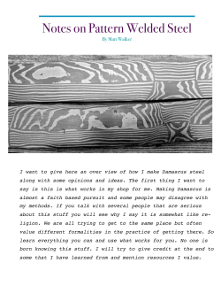


© Copyright 2026