
SKYLINE CORPORATION MANUFACTURED HOME
SKYLINE
CORPORATION
MANUFACTURED
HOME
INSTALLATION
MANUAL
TABLE OF CONTENTS
Chapter 1 — Introduction ................................................. 4
Chapter 2 — Definitions ................................................. 5
Chapter 3 — Site Preparation
Zone Maps .................................................. 6
Site Grading ............................................. 7-8
Description of Soils .................................... 8
Chapter 4 — Foundation and Support Requirements
Piers ........................................................... 9
Design Requirements ................................. 9
Design Procedures .............................. 9-10
Acceptable Footings ................................ 10
Placement in Freezing Climates .............. 10
Proper Sizing of Footings ......................... 10
Permanent Foundations .......................... 10
Flood-Prone Areas .................................... 10
Severe Wind Areas ................................... 10
Special Snow Load Conditions ................. 10
Important Reference Documents .............. 10
Typical Installations ...................................11
Typical Pier Construction .......................... 12
Support Requirements ......................... 13-15
- Single Wides ....................................... 13
- Double Wides ................................. 14-15
Sidewall Openings .................................... 15
Pavilion Dormer Blocking ......................... 16
Footing Sizes ...................................... 16 -17
Chapter 5 — Set-Up Procedures
Moving Home to Location ......................... 18
Positioning Home ..................................... 18
Leveling and Blocking .......................... 18-20
- Single Wides .................................. 18-19
- Double Wides ...................................... 20
Adjustable Outrigger ................................. 21
Use of Water Level ................................... 22
Double Wide Interconnection .............. 23-24
Tie Down Instructions .......................... 25-26
Over-The-Roof Straps .............................. 26
Anchor Tables Wind Zone I .................. 27-29
Anchor Tables Wind Zone II & III ......... 30-31
Anchor Tables for 102” Sidewalls ............. 32
Longitudinal Tie Down Instructions ........... 33
Tie Down Example .................................... 34
WARNING
ONLY EXPERIENCED PERSONS
KNOWLEDGEABLE OF MANUFACTURED
HOME SET-UP PROCEDURES SHOULD SET UP
THIS HOME
Double Wide Exterior Closure ............... 35-37
- Masonite Siding ..................................... 35
- Vinyl Lap Siding ..................................... 36
- HardiPanel & HardiPlank Siding ............ 37
Installation of Shingle Roof ................... 38-39
Double Wide Utility Interconnection ....... 40-43
- Bonding ................................................ 40
- Electrical Crossover .............................. 40
- Heating Crossover ................................. 41
- Gasline Crossover ................................. 42
- Waterline Cross Connect ....................... 42
- Drainline Cross Connect ....................... 43
Installation of Exterior Light Fixtures .......... 43
Venting of Skirting and Crawlspace ............ 43
Metal Roof Tightening ................................. 43
Porches & Decks ........................................ 43
Chapter 6 — Installation of Optional Features
Electrical Dryer Venting .............................. 44
Gas Dryer Installation ................................. 44
Gas Water Heater Venting .......................... 44
Grill/Range Venting ..................................... 44
Paddle Fan Installation .......................... 45-46
- Flush Ridge Beam ................................. 45
- Protruding Ridge Beam ......................... 46
- False Beam ........................................... 46
Air Conditioning Electrical Connect ............ 47
Evaporative Cooler ..................................... 47
Dealer Installed Blend Air ........................... 48
Expanding Rooms, Slide-Outs ................... 49
Site Attached Structures ............................. 49
Hinged Roofs and Eaves ............................ 49
Ceiling Fans ................................................ 49
Telephone and Cable TV ............................ 49
Fireplace Installation ................................... 49
Field Installed Hearth .................................. 49
Field Installed Fireplace Chimney .............. 50
Chapter 7 — Utility System Connection and Testing
Water .......................................................... 51
Drainage - Connection ................................ 51
Drainage - 1, 1-1/2, 1-3/4 & 2 Bath ............. 51
Gas ........................................................ 51-52
Electrical ..................................................... 53
Outside Panel Box ...................................... 53
Electrical System Test ................................. 53
Multi-Section Frame Bonding ..................... 54
Typical Under-Chassis
Feed Connections ................................... 54
Typical Meter Base Installation ................... 55
Meter Base & Panel w/Masthead ............... 55
Chapter 8 — Protective Window Coverings ................ 56-61
Chapter 9 — Final Inspection
Final Inspection .......................................... 62
Installation Inspection Checklist ................. 62
NOTE: THIS MANUAL IS INTENDED TO INSTRUCT AND TO ASSIST ALREADY QUALIFIED PERSONNEL IN
PROPER INSTALLATION OF SKYLINE MANUFACTURED HOMES. IT IS NOT INTENDED TO ENABLE SOMEONE UNFAMILIAR WITH MANUFACTURED HOME INSTALLATION TO PERFORM THE INSTALLATION.
SET-UP SHOULD BE DONE ONLY BY QUALIFIED PEOPLE. WHOEVER DOES THE SET-UP SHOULD GUARANTEE THEIR WORK IN WRITING FOR A REASONABLE TIME AND SHOULD, IF NECESSARY, AGREE TO RELEVEL THE HOME WITHIN 90 DAYS AFTER THE INITIAL SET-UP.
Chapter 1
INTRODUCTION
PLEASE READ ALL INSTRUCTIONS PRIOR TO SET-UP!
This Skyline home was engineered, constructed and inspected
for conformance to the Federal Manufactured Home Construction
and Safety Standards in effect on the date of manufacture. This
National Standard sets forth comprehensive requirements for design
construction, fire safety, plumbing, heating systems and electrical
systems for manufactured homes designed to be used as dwellings.
This manual contains detailed installation instructions, including specifications and procedures for erection and hookup of your
manufactured home. It has been written in an objective and easyto-understand manner so it can be understood by people without
extensive technical training. It discusses the set-up of the home from
preparing the site through final inspection. It includes many tables
and figures giving important data for proper set-up. Careful adherence to this manual by the homeowner and installation crew, and
consultation with a registered professional or structural engineer in
those unusual circumstances it does not cover, will assure you of a
quality, safe and affordable home for many years to come.
Prior to locating or relocating your home, contact the local authority having jurisdiction for installation to see if permits
for such procedures as blocking, anchoring, or utility connections
are required. Inspections may be required during installation. On
private property, zoning or development covenants may apply and
should be taken into consideration. NOTE: Preparations of the site,
when accomplished by others than the home installer, may not be in
accordance with these instructions.
THE IMPORTANCE OF CORRECT SET-UP CANNOT BE
OVEREMPHASIZED. Correct set-up is absolutely essential to
homeowner satisfaction. If you are not absolutely certain of the
proper procedure or you encounter unusual conditions, please
contact your factory service representative.
THE INSTRUCTIONS CONTAINED HEREIN ARE MINIMUM REQUIREMENTS. APPLICABLE LOCAL OR STATE
LAW MAY HAVE OTHER OR GREATER REQUIREMENTS
WHICH MUST BE COMPLIED WITH TO OBTAIN OR REGAIN
THE RIGHT TO OCCUPY THE HOME.
The recommended procedures contained in this manual are intended to assist in proper installation of this home. Field experience
may justify alternate acceptable procedures which, when completed,
result in performance at least equal to that which will result from
conformance to the details and specifications herein. For example,
on double wide installation you may find it advantageous, due to local conditions, to bolt the floors together prior to bolting roof halves
together, or vice versa. Either method is acceptable as long as the
bolting schedule is adhered to.
NOTE: A MANUFACTURED HOME SET UP IN THE
WRONG STRUCTURAL ZONE DOES NOT MEET THE
REQUIREMENTS OF THE FEDERAL MANUFACTURED
HOME CONSTRUCTION AND SAFETY STANDARDS.
BEFORE COMMENCING SET-UP, SEE CONSTRUCTION
INFORMATION, LOCATED IN THE MASTER BEDROOM
CLOSET OR AT THE ELECTRICAL DISTRIBUTION PANELBOARD, FOR DESIGNATION OF ZONE FOR WHICH
THE HOME WAS CONSTRUCTED.
SPECIAL CONSTRUCTION SUCH AS EXPANDO
UNITS, TRIPLE WIDE UNITS, AND PERIMETER BLOCKED
UNITS WILL BE COVERED IN SUPPLEMENTS TO THIS
MANUAL. CONTACT YOUR FACTORY OR DEALER IF
THIS HOME HAS ANY SUCH FEATURES AND YOU DO NOT
HAVE THE APPLICABLE SUPPLEMENTS.
WARNING: ONLY TRAINED CREWS SHOULD INSTALL
THE HOME. INSTALLERS SHOULD FOLLOW THE SAFETY INSTRUCTIONS PROVIDED IN THIS MANUAL.
THIS HOME WEIGHS SEVERAL TONS
USE ENOUGH TEMPORARY WOOD BLOCKING TO SUPPORT THE HOME DURING SET-UP.
No one should be allowed under the home unless it is securely in
place, even if it is not moving.
The technical content of the Installation Manual has been reviewed by PFS Corporation and found to be in
accordance with the Federal Manufactured Home Construction and Safety Standards.
4
Chapter 2
DEFINITIONS
ANCHORING EQUIPMENT: Straps, cables, turnbuckles and chains, including tensioning devices, that are used with
ties to secure a manufactured home to ground anchors.
ANCHORING SYSTEM:
A combination of ties, anchoring equipment, and ground anchors that will, when properly designed and installed, resist the wind’s overturning the home or moving it sideways.
FOOTING:
That part of the support system that sits directly on the ground at, below or partly below grade to support the
piers.
PERIMETER SUPPORT:
The portion of a support system that supports the sidewalls at the floor line.
PIER: That portion of the support system between the footing and the manufactured home, exclusive of caps and shims.
Types of piers include, but are not limited to, the following:
1. Manufactured Steel Stands
2. Manufactured Concrete Stands, and
3. Concrete Blocks
SITE, MANUFACTURED HOME:
A parcel of land designed and designated for the location of one manufactured
home, its accessory building or structures, and accessory equipment for exclusive use of the home’s occupants.
STABILIZING SYSTEM:
A COMBINATION OF PROPERLY INSTALLED ANCHORING AND SUPPORT SYSTEM.
STAND, MANUFACTURED HOME:
That area of a manufactured home site which has been reserved for place-
ment of a manufactured home.
SUPPORT SYSTEM:
A combination of footings, piers, caps and shims that will, when properly installed, support the
manufactured home.
5
SITE PREPARATION
Chapter 3
ZONE MAPS OF THE UNITED STATES
ROOF LOAD ZONE MAP
HEATING AND COOLING ZONE MAP
IN WIND ZONES II AND III, UNLESS THE HOME AND
ITS ANCHORING AND FOUNDATION SYSTEM HAVE
BEEN DESIGNED FOR THE INCREASED REQUIREMENTS OF EXPOSURE ‘D’ OF ANSI/ASCE 7-88, IT
SHOULD NOT BE LOCATED WITHIN 1500 FEET OF
THE COASTLINE.
WIND ZONE MAP
The following local governments listed by state (county/
parishes, unless noted otherwise) are located in WIND
ZONE II:
ALABAMA - Baldwin and Mobile
FLORIDA - All counties except those identified as being within
Wind Zone III.
GEORGIA - Bryan, Camden, Chatham, Glynn, Liberty and
McIntosh
LOUISIANA - Acadia, Allen, Ascension, Assumption, Calcasieu, Cameron, East Baton Rouge, East Feliciana, Evangeline, Iberia. Iberville, Jefferson Davis, LaFayette, Livingston,
Pointe Coupee, St. Helena, St. James, St. John the Baptist,
St. Landry, St. Martin, St. Tammany, Tangipahoa, Vermillion,
Washington, West Baton Rouge and West Feliciana.
MAINE - Hancock and Washington
MASSACHUSETTS - Barnstable, Bristol, Dukes, Nantucket
and Plymouth
MISSISSIPPI - George, Hancock, Harrison, Jackson, Pearl
River and Stone
NORTH CAROLINA - Beaufort, Brunswick, Camden, Chowan,
Columbus, Craven, Currituck, Jones, New Hanover, Onslow,
Pamlico, Pasquotank, Pender, Perquimans, Tyrrell and
Washington
SOUTH CAROLINA - Beaufort, Berkeley, Charleston, Colleton, Dorchester, Georgetown, Horry, Jasper and Williamsburg.
6
WIND ZONE II (continued):
TEXAS - Arkansas, Brazoria, Calhoun, Cameron, Chambers,
Galveston, Jefferson, Kenedy, Kleberg, Matagorda, Nueces,
Orange, Refugio, San Patricio and Willacy
VIRGINIA (The cities of)- Chesapeake, Norfolk, Portsmouth,
Princess Anne and Virginia Beach
The following local governments listed by state (county/parishes, unless noted otherwise) are located in WIND ZONE III:
FLORIDA - Broward, Charlotte, Collier, Dade, Franklin, Gulf,
Hendry, Lee, Martin, Manatee, Monroe, Palm Beach, Pinellas
and Sarasota
LOUISIANA - Jefferson, La Fourche, Orleans, Plaquemines,
St. Bernard, St. Charles, St. Mary and Terrebonne
NORTH CAROLINA - Carteret, Hyde and Dare.
The following states and territories are within
WIND ZONE III:
State of HAWAII
ALASKA - Costal regions between the 90 mph isotach on
ASCE 7-88 wind map and the coast.
U.S. TERRITORIES - American Samoa, Northern Mariana
Islands, Trust Territory of Pacific Islands, Guam, Puerto Rico
and U.S. Virgin Islands.
SITE PREPARATION (Continued)
SITE PREPARATION
The importance of site preparation for a problem-free installation cannot be overstated. All vegetation must be removed
from under the home site. The site must be properly graded and
sloped to provide for storm drainage runoff. In particular, the
area under the home must be graded to prevent water accumulation. Skyline Corp. recommends the home site slope 10 feet
in all directions away from the home. If the home is sited on
sloping terrain or a hillside, the soil must be graded on all sides
to channel storm runoff around the home and not under it. If the
home is set in a pit, it is extremely important to provide water
drainage from under and around the home.
WARNING: THE AREA UNDER AND AROUND THE HOME
MUST BE SLOPED TO PREVENT WATER ACCUMULATION.
EXCESSIVE MOISTURE UNDER THE HOME CAN CAUSE
UNNECESSARY DETERIORATION, AND CAUSE CONDENSATION PROBLEMS, WHICH COULD AFFECT THE HOME’S
WARRANTY. IT COULD ALSO AFFECT THE STABILITY OF
THE FOOTINGS AND PIERS WHICH SUPPORT THE HOME.
If the home is to be perimeter skirted or “pit-set,” ventilation of
the under-floor area is required to minimize the effect of moisture
under the home. Ventilation openings must be provided in the
under-floor enclosure or skirting on at least three (3) sides (preferable on all sides) with a net area of at least one square foot per
150 square feet of floor area. The required ventilators are
to be approximately equally spaced around the perimeter
of the home with a ventilation opening within three (3) feet
of each outside corner.
Proper support of the manufactured home must allow
for soil conditions in the immediate area. Pier footings
must be placed on firm undisturbed soil (not loose fill) or
soil which has been compacted to at least 90 percent of
its maximum relative density. Support piers may also be
placed directly on concrete slabs designed for manufactured home placement as found in manufactured home
communities.
After completion of grading and filling (if necessary), the
bearing capacity of the soil at the depth of the footings
should be determined. A pocket penetrometer (available from engineering supply houses) or other method
acceptable to local jurisdictions may be used. If the soil
cannot be tested but can be identified, use the foundation
bearing pressures shown in Figure 3-1 as a guide. If the
soil cannot be identified, use the lowest value, 1,000 PSF.
Under unusual conditions, or if the soil appears to be peat
or uncompacted soil, consult a local geologist or professional engineer for aid.
CAUTION
EXCESSIVE WATER IN THE SOIL UNDER THE HOME WILL CAUSE UNNECESSARY DETERIORATION OF THE HOME
AND AFFECT THE COMFORT LEVEL IN THE HOME. CONTINUOUS STANDING WATER UNDER THE HOME CAN CAUSE
CONDENSATION PROBLEMS AND AFFECT THE HOME’S WARRANTY.
PREVENTION OF WATER BENEATH THE HOME
SINGLE SECTIONAL
DO CROWN AND
GRADE SITE TO
SLOPE AWAY
FROM HOME
DON’T GRADE
SITE SO THAT
WATER COLLECTS
BENEATH THE HOME
DOUBLE SECTIONAL
DO CROWN AND
GRADE SITE TO
SLOPE AWAY
FROM HOME
DON’T GRADE
SITE SO THAT
WATER COLLECTS
BENEATH THE HOME
TRIPLE SECTIONAL
DO CROWN
AND GRADE
SITE TO
SLOPE AWAY
FROM HOME
DON’T GRADE
SITE SO THAT
WATER
COLLECTS
BENEATH
THE HOME
7
SITE PREPARATION (Continued)
GROUND BARRIER
There is a strong tendency for ground moisture to be drawn into the home, greatly complicating efforts to control humidity and
condensation.
A ground moisture-vapor retarder of 6 mil. rated polyethylene plastic, vinyl or similar material laid on the ground surface under
the home is recommended to assist in controlling the humidity in the home.
General Description of Soils
Allowable Pressure
(Pounds Per Square Foot)
Soil Type
Based on the Unified Classification System
No allowances made for overburden pressure, embedment,
depth, water table height, or settlement problems.
4,000 and up
Rock or Hard Pan
Sandy Gravel and Gravel
2,000
Sand, Silty Sand, Clayey Sand
Silty Gravel, or Clayey Gravel
1,500
Clay, Sandy Clay,
Silty Clay, or Clayey Silt
1,000
Uncompacted Fill
Special Analysis is Required
Peat or Organic Clays
Special Analysis is Required
NOTE:
To be used only when none of the following is available:
a. Soils investigation and analysis of the site.
b. Compliance with the local building code.
c. Competent opinion by a local engineer or building official.
d. If the soil bearing capacity is less than 1,000 PSF, consult a professional engineer for foundation system requirements.
FIG. 3-1
8
CHAPTER 4
FOUNDATION AND SUPPORT
REQUIREMENTS
NOTE: This chapter covers only foundations. Page 11
summarizes the usual types. Set-up procedures and
methods for securing the home to its foundation are discussed
in Chapter 5.
A home that is certified for a higher roof load zone than the
area that it is installed may be set on a foundation system that
is designed for the roof load zone for that area of the country.
For example, a home that is certified to withstand a 30 PSF
roof load is installed in a 20 PSF roof load zone area. The
support under the home need only be designed for the 20 PSF
roof load, in accordance with the requirements set forth in this
manual.
PIERS
Importance. Incorrect size, location or spacing of piers may
cause serious structural damage to the home. It is important
to install piers around the perimeter if required for the home.
Failure to do so may lead to sagging floors, walls and roofs.
Acceptable Types. Piers may be concrete blocks or pressure
treated wood, capped and shimmed with wedges, or adjustable manufactured metal or concrete devices (see Figure
4-2). Manufactured piers should be listed and labeled for the
required load capacity.
DESIGN REQUIREMENTS
Load-Bearing Capacity. The load that each pier must carry
depends on factors such as the dimensions of the home, the
roof live load, the spacing of the piers, and the way they are
used to support the home. Center beam/marriage wall blocking
is required for multisection homes.
See tables 1 and 2 for pier capacities. Manufactured piers
must be rated to at least these capacities, and locally constructed piers must be designed to transmit these loads safely.
Configuration. Figure 4-2 shows the recommended arrangement of concrete piers constructed on-site. Concrete blocks
should have nominal dimensions of at least 8” x 16”. They
must be stacked with their hollow cells aligned vertically.
When piers are constructed of blocks stacked side-by-side,
every layer should be at right angles to the previous one (See
Figure 4-2).
Cap hollow block piers as shown in Figure 4-2 to distribute
the structural load evenly across them. Caps may be of solid
masonry or hard wood, and of the same length and width as
the piers they rest upon. Avoid plywood, as it may lead to
unwanted settling or movement.
Use 4” x 6” hardwood shims (wedges) to level the home and
fill any gaps between the base of the I-beam and the top of the
pier cap. Always use shims in pairs (See Figure 4-2). Drive
them in tightly so they do not occupy more than 1” of vertical
space. When the space to be shimmed is less than the
minimum thickness of available caps or concrete blocks,
dimension lumber may be used under the caps.
Select manufactured pier heights so that their adjustable
risers do not extend more than recommended by the
manufacturer when finally positioned.
All piers must rest on footings that either extend below
the frost line or are otherwise protected from frost effects,
and are placed on either undisturbed soil or compacted
fill.
DESIGN PROCEDURES
Piers Less Than 36” High. Construct piers less than 36” high
out of single, open or closed-cell concrete blocks, 8” x 8” x
16”. Install them so that the long side is at right angles to the
supported I-beam (See Figure 4-2). Position open cells vertically upon the footers. (See Figure 4-1). Horizontal offsets
should not exceed 1/2” top to bottom. Mortar is not normally
required. Manufactured piers should be listed and labeled. Do
not extend their adjusting studs beyond the limits specified by
the manufacturer.
Piers 36” to 80” High. Construct all piers between 36” and
80” high, and all corner piers over three (3) blocks high, out of
double, interlocked concrete blocks (See Figure 4-2). Mortar
will not normally be required.
Piers Over 80” High. Where permitted by local codes, lay
them in concrete mortar with steel reinforcing bars inserted
in the block cells and fill the cells with concrete. Where such
construction is not permitted by local codes, have piers over
80” high designed by a registered professional or structural
engineer.
Location and Spacing. The location and spacing of piers
depend upon the dimensions and weight of the home, the roof
load zone, size, and type of construction of the footings.
Other factors such as the location of doors or other openings
and heavy pieces of furniture are also important. In general
locate piers no more than 2’ from either end, and not over 10’
o.c.
Single-Section Homes. Figure 5-2 shows the recommended
locations and spacing of piers for single-section homes.
Multi-Section Homes. Figure 5-3 shows the recommended
location and spacing of piers for multi-section homes.
Under Doors and Heavy Furniture. Place additional piers
on both sides of exterior doors, sidewall openings wider than
4’ (such as sliding glass doors), at Pavilion dormers, under
porch posts, wood stoves, and under the expected locations of
heavy pieces of furniture such as pianos, organs, waterbeds,
etc.
9
FOUNDATION AND SUPPORT REQUIREMENTS (Continued)
DESIGN PROCEDURES (Continued)
Footings. Support every pier with a properly designed
footing, as follows.
ACCEPTABLE TYPES OF FOOTINGS.
Concrete. Footings may consist of precast or poured-in-place
concrete, pads, slabs, or ribbons with a 28-day compressive
strength at 3,000 psi.
Pressure-Treated Permanent Wood. Two layers of 2” thick
pressure-treated wood planks, with the long dimension of the
second layer placed perpendicular to that of the first, fastened
with cut edges painted or retreated, may also be used.
Other Materials. You may also use other materials approved
for this use by local authorities if they provide equal loadbearing capacity and resistance to decay.
PLACEMENT IN FREEZING CLIMATES.
Conventional Footings. For frost-susceptible soils, the most
cost effective method of preventing the harmful effects of
ground frost heave is usually by placing the footing below the
frost line. Consult local authorities to determine frost penetration. In the absence of a local code, use the frost penetration
map as a guide.
Existing manufactured home communities may be located on
frost-susceptible soils in which homes historically have been
installed on piers or slabs located above the frost line. For
these communities, if there is a history of these homes not
experiencing any deleterious effects from frost-heave and the
homes are setup, supported and skirted as described herein,
then footings are not required to extend below the frost line.
Floating Slab System. When properly engineered by a registered professional engineer, compatible with the anchorage
requirements of Chapter 5, and acceptable to the local authority having jurisdiction, a “floating slab system” may be used
above the frost line.
Insulated Foundations. Footings may also be placed above
the frost line when the home is provided with a perimeter
foundation or skirting having insulation properties sufficient to
prevent freezing of the soil under or adjacent to every loadbearing component of the foundation and acceptable for this
purpose by the local authority having jurisdiction. Useful
design guidelines may be found in references at the end of this
chapter. Insulation systems should be compatible with the requirement to cross ventilate the entire space under the home.
bearing perimeter foundation). A permanent foundation design,
which meets most local codes, may be available from Skyline
Corporation. Please contact the Skyline division which manufactured the home or Skyline’s National Director of Consumer
Affairs.
Flood-Prone Areas. Skyline Corporation does not recommend
locating homes in river or coastal flood-prone areas.
Special elevation and anchoring techniques are required when
locating in a flood-prone area. Consult a registered professional
or structural engineer to make sure that the home design and
construction conform to applicable federal, state and local codes
and regulations. The FEMA publication listed below contains
design and construction recommendations.
Severe Wind Areas. Special foundation and anchoring techniques are required when locating in a severe wind area.
Consult a registered professional or structural engineer. The
HUD foundations design guide referenced herein contains
recommendations for designing foundations and anchoring
systems. Do not place your home in a wind zone more severe
than the one indicated on the data plate located by your home’s
main electrical panel.
Special Snow Load Conditions. Homes designed for and
located in heavy snowfall areas or subject to other extreme
loading conditions may require special piers or footings. See
tables and/or special manufacturer’s instructions provided with
your home.
IMPORTANT REFERENCE DOCUMENTS
•
Foundation plans available from manufacturer.
•
ANSI/NCSBCS A225.1-1987, “Manufactured Home
Installations,” NCSBCS, 505 Huntmar Park Drive, Herndon,
VA 22070, (703)437-0100.
•
ASCE 7-88, “Minimum Design Loads for Buildings and
other Structures,” ASCE, 345 East 47th Street, New York,
NY 10017-2398.
•
FEMA 85, “Manufactured Home Installation in Flood
Hazard Areas,” FEMA, Washington, DC 20472,
(202)646-2708, September, 1985.
•
HUD Handbook 4930.3 (1989), “Permanent Foundations
Guide for Manufactured Housing,” HUD, 415 7th Street,
S.W., Washington, CD 20410.
•
“All Weather Wood Foundation Systems Manual,” National
Forest Products Association, 1619 Massachusetts Ave.,
N.W., Washington, DC 20036, June, 1976.
Proper Sizing of Footings. Proper sizing of footings depends
•
upon the load-carrying capacity of both the piers and the soil.
See Table 4 for recommended footing sizes. See Table 4B for
minimum required concrete footing thickness. Footing size in
no case shall be less than 144 sq. in. or smaller than the pier it
supports.
•
Permanent Foundations. Check local building codes and
regulations and consult a registered professional or structural
engineer when you are setting your home on a permanent
foundation (such as a full basement, crawl space or load10
“Design Guide for Frost-Protected Shallow Foundations,”
Prepared for U.S. Dept. of Housing and Urban Development by NAHB, Upper Marlboro, MD, June, 1994,
Instrument No. DU100K000005897.
“Building Foundation Design Guidebook,” Document No.
DE 88013350, National Technical Information Service,
5285 Port Royal Road, Springfield, VA 22161.
FOUNDATION AND SUPPORT REQUIREMENTS (Continued)
MANUFACTURED HOME INSTALLATIONS
SINGLE OR MULTI-SECTION HOMES
TYPES OF FOUNDATION SYSTEM - MAIN COMPONENTS(*)
1. Piers-Ground Anchors. Home rests on piers of concrete block, formed-in-place concrete, permanent wood or steel
pedestals on permanent wood, crushed stone or concrete footers. Ground anchors in soil angled to resist straps or
embedded in concrete deadmen in soil. Straps tied to the frame, with or without over-the-top straps.
2. Concrete Slab or Continuous Footing. Home rests on a concrete slab or ribbons of concrete. Straps tied between
frame and perimeter footers or concrete slab. Skyline Corp. recommends installing earth anchors prior to pouring
concrete slab. Concrete slab should be sloped to prevent water accumulation under home.
3. Pile/Post System. Home rests on piles/posts placed sufficiently deep in the ground to resist all wind, snow, frost
heave and earthquake forces. Straps fasten home to the piles/posts or caps placed thereon.
4. Concrete or Concrete Block Load-Bearing Perimeter Walls (Basement or Crawl Space). Home rests on exterior
loadbearing walls which sit on concrete footings’ weight to resist all external forces. The floor connection to foundation
resists external forces.
*For Skyline multi-section homes, the mating walls are supported by piers or support walls with straps and ground
anchors, providing resistance to downward and uplift forces.
TYPICAL FOOTING PADS FIG. 4-1
16”
16”
16”
SINGLE PAD FOOTING
SINGLE PAD FOOTING
8”
DOUBLE PAD
FOOTING
24”
11 1/4”
DOUBLE PAD
FOOTING
DOUBLE PAD
FOOTING
TRIPLE PAD FOOTING
LOAD DISTRIBUTING
PAD FOR SUPPORT
TWO DOUBLE PAD
FOOTING
TRIPLE PAD FOOTING
LOAD DISTRIBUTING PAD
FOR SUPPORT (24” X 24” X 4”)
TWO DOUBLE PAD FOOTING
QUAD PAD FOOTING
16”x16”x4” CONCRETE PAD FOOTINGS
8”x16”x4” CONCRETE PAD FOOTINGS
2”x12”x24” WOOD PAD FOOTINGS
11
FOUNDATION AND SUPPORT REQUIREMENTS (Continued)
TYPICAL PIER CONSTRUCTION
I-Beam frame
12” to 36” in height
Gap between top of pier and main frame may be hardwood plate (not exceeding 2” in thickness)
and shims (not exceeding 1” in thickness). Shims shall be at least 4” wide and 6” long, fitted and
driven tight between wood plate or pier and main frame. 2” or 4” solid concrete block may fill
remainder of gap.
Cap — Wood or concrete, 2” x 8” x 16” installed with 16” dimension
perpendicular to the I-beam frame.
Single open or closed cell concrete blocks 8” x 8” x 16” (open cells
placed vertically upon footer) installed with 16” dimension
perpendicular to the I-beam frame.
Footing - Solid concrete or other product approved for the purpose.
Size according to Table 4.
Ground Level
Footing below frost line when subject to frost heaving.
SINGLE BLOCK PIER - 8000 LBS. MAXIMUM CAPACITY. PIER
CAPACITY MUST BE EQUAL TO OR MORE THAN REQUIRED
FOOTER CAPACITY.
Concrete grouting
Cap - Solid concrete
block or equivalent.
Steel reinforcing bars
Double Interlocked Blocks,
Max. Height is 80”.
For piers exceeding 80 inches
in height the concrete blocks
should be filled with concrete
grouting and steel reinforcing
rods should be used.
DOUBLE BLOCK PIER - 14000 LBS. MAXIMUM CAPACITY. PIER CAPACITY
MUST BE EQUAL TO OR MORE THAN REQUIRED FOOTER CAPACITY.
Footings placed on firm undisturbed soil or in controlled fill free of grass and organic materials compacted to a minimum load
bearing capacity of 1000 PSF.
30
35 40
25
30 20
15
10
6
3
1
Frost Penetration Map
1
AVERAGE DEPTH OF FROST PENETRATION — IN INCHES
SOURCE: U.S. Dept. of Commerce Weather Bureau
12
FIG. 4-2
FOUNDATION AND SUPPORT REQUIREMENTS (Continued)
SUPPORT REQUIREMENTS
The design loads and minimum footing sizes used in the
selection of the support structure are set forth in Table 4.
The loads and footing sizes are the minimum values to be
used for the support structure and are based on the
indicated roof live load and a floor live load of 40 PSF.
The support requirements for homes designed for 60 PSF and
higher roof load (and those specifically indicated middle and north
zone homes) are found in the supplement accompanying this
manual entitled “Manufactured Home Installation for Perimeter
Blocking.”
All load bearing supports and footings may be subject to
approval by the local Enforcement Agency.
Contact the Skyline division that built the home for more
information concerning perimeter blocking.
TABLE 1
PIER-LOADING UNDER MAIN I-BEAMS
SINGLE-WIDE HOMES
14’ WIDE HOMES
12’ WIDE HOMES
Pier
Spacing
Under
Main
I-Beams
(Ft.)
4
5
6
7
8
9
10
Wt. Per Foot
See Note 4
16’ WIDE HOMES
Pier Load
(Lbs)
20 PSF
Roof
Zone
Pier Load
(Lbs)
30 PSF
Roof
Zone
Pier Load
(Lbs)
40 PSF
Roof
Zone
Pier Load
(Lbs)
20 PSF
Roof
Zone
Pier Load
(Lbs)
30 PSF
Roof
Zone
Pier Load
(Lbs)
40 PSF
Roof
Zone
Pier Load
(Lbs)
20 PSF
Roof
Zone
Pier Load
(Lbs)
30 PSF
Roof
Zone
Pier Load
(Lbs)
40 PSF
Roof
Zone
2130
2660
3190
3720
4250
4780
5320
532
2420
3020
3620
4230
4830
5440
6040
604
2560
3190
3830
4470
5110
5750
6380
638
2410
3020
3620
4220
4820
5430
6030
603
2740
3420
4110
4790
5480
6160
6850
685
2940
3670
4410
5140
5880
6610
7340
734
2700
3370
4050
4720
5400
6070
6750
675
3060
3830
4590
5360
6120
6890
7650
765
3320
4150
4980
5810
6640
7470
8300
830
NOTES:
1. See Table 4 for minimum footing sizes based on pier loads and allowable soil bearing capacities. The footing sizes and pier
loads are minimums required for the applicable conditions. The footing shall not be smaller than the pier it supports of 144
square inches.
2. The maximum spacing of supports is not to exceed 10 feet.
3. Where it is impractical to maintain spacing, such as in the axle area, the average of the distance to each adjacent support
may be used to determine support requirements. For example: if the distances to the adjacent supports were 6’-0” and 8’-0”,
the average spacing would be 7’-0”.
6’-0”
Pier A
8’-0”
Pier B
Pier C
The average spacing for pier B would be (6 + 8) / 2 = 7 ft., therefore, pier B would be designed for 7 ft. pier spacing.
4. The last line in the above Table is the weight per foot each main I-beam is carrying. Multiply this number by the span a pier is
carrying to determine the required capacity of that pier.
13
FOUNDATION AND SUPPORT REQUIREMENTS (Continued)
TABLE 2
PIER LOADING UNDER MAIN I-BEAMS
DOUBLE-WIDE HOMES
20’ WIDE HOMES
24’ WIDE HOMES
26’ & 28’ WIDE HOMES
32’ WIDE HOMES
Pier
Spacing Pier Load Pier Load Pier Load Pier Load Pier Load Pier Load Pier Load Pier Load Pier Load Pier Load Pier Load Pier Load
(Lbs)
(Lbs)
(Lbs)
(Lbs)
(Lbs)
(Lbs)
(Lbs)
(Lbs)
(Lbs)
(Lbs)
Under
(Lbs)
(Lbs)
20 PSF 30 PSF 40 PSF 20 PSF 30 PSF 40 PSF 20 PSF 30 PSF 40 PSF 20 PSF 30 PSF 40 PSF
Main
Roof
Roof
Roof
Roof
Roof
Roof
Roof
Roof
Roof
Roof
I-Beams
Roof
Roof
Zone
Zone
Zone
Zone
Zone
Zone
Zone
Zone
Zone
Zone
(Ft.)
Zone
Zone
4
5
6
7
8
9
10
Wt. Per Foot
See Note 5
1810
2270
2720
3170
3630
4080
4540
454
2060
2580
3100
3610
4130
4640
5160
516
2170
2710
3260
3800
4340
4880
5420
542
2100
2630
3150
3680
4200
4730
5250
525
2390
2980
3580
4180
4770
5370
5970
597
2560
3190
3830
4470
5110
5750
6380
638
2360
2950
3540
4130
4720
5310
5900
590
2630
3350
4020
4690
5360
6030
6700
670
2940
3670
4410
5140
5880
6610
7340
734
2680
3350
4020
4690
5360
6030
6700
670
3000
3750
4500
5250
6000
6750
7500
750
3320
4150
4980
5810
6640
7470
8300
830
NOTES:
1. See Table 4 for minimum footing sizes based on pier loads and allowable soil bearing capacities. The footing sizes and pier
loads are minimum required for the applicable conditions. The footing shall not be smaller than the pier it supports of 144
square inches.
2. The maximum spacing of supports is not to exceed 10 feet.
3. Where it is impractical to maintain spacing, such as in the axle area, the average of the distance to each adjacent support
may be used to determine support requirements. For example: if the distances to the adjacent supports were 6’-0” and 8’-0”,
the average spacing would be 7’-0”.
6’-0”
Pier A
8’-0”
Pier B
Pier C
The average spacing for pier B would be (6 + 8) / 2 = 7 ft., therefore, pier B would be designed for 7 ft. pier spacing.
4. Concentrated loads at marriage line (see Table 3).
5. The last line in the above Table is the weight per foot each main I-beam is carrying. Multiply this number by the span a pier
is carrying to determine the required capacity of that pier.
14
FOUNDATION AND SUPPORT REQUIREMENTS (Continued)
TABLE 3
PIER LOADING UNDER CENTERLINE BEAMS
DOUBLE-WIDE HOMES
24’ WIDE HOMES
20’ WIDE HOMES
26’ & 28’ WIDE HOMES
32’ WIDE HOMES
Span Pier Load Pier Load Pier Load Pier Load Pier Load Pier Load Pier Load Pier Load Pier Load Pier Load Pier Load Pier Load
Between
(Lbs)
(Lbs)
(Lbs)
(Lbs)
(Lbs)
(Lbs)
(Lbs)
(Lbs)
(Lbs)
(Lbs)
(Lbs)
(Lbs)
Columns 20 PSF 30 PSF 40 PSF 20 PSF 30 PSF 40 PSF 20 PSF 30 PSF 40 PSF 20 PSF 30 PSF 40 PSF
(Ft.)
Roof
Roof
Roof
Roof
Roof
Roof
Roof
Roof
Roof
Roof
Roof
Roof
See note 1
Zone
Zone
Zone
Zone
Zone
Zone
Zone
Zone
Zone
Zone
Zone
Zone
6
10
12
14
16
18
20
24
900
1500
1800
2100
2400
2700
3000
3600
1200
2000
2400
2800
3200
3600
4000
4800
1500
2500
3000
3500
4000
4500
5000
6000
1080
1800
2160
2520
2880
3240
3600
4320
1440
2400
2880
3360
3840
4320
4800
5760
1800
3000
3600
4320
4800
5400
6000
7200
1260
2100
2520
2940
3360
3780
4200
5040
1680
2800
3360
3920
4480
5040
5600
6720
2100
3500
4200
4900
5600
6300
7000
8400
1350
2250
2700
3150
3600
4050
4500
5400
1800
3000
3600
4200
4800
5400
6000
7200
2250
3750
4500
5250
6000
6750
7500
9000
NOTES:
1) Where a column is located between two openings, sum the loads for each opening to obtain the required pier load.
2) See table 4 for minimum footing sizes based on pier loads and allowable soil bearing capacities.
3) The concentrated load consist of roof load only.
4) Pier locations at the marriage wall are marked with paint or metal indicator straps.
5) Piers used side by side to obtain the required load are permissible.
PIER LOADING AND INSTALLATION UNDER SIDEWALL DOORS AND WINDOWS
Unit sidewall
Unit sidewall
Typical door or window
opening - Width varies
- see table below.
A
Floor joists
Floor joists
Typical Pier
4x4 block, 4” longer
than joist spacing.
Installed such that it
spans joists on either
side of door jamb.
Typical Pier
See note 6.
A
Pier installed when
joist is not under
door jamb.
Pier installed when
joist is under
door jamb.
48” OPENING
SECTION ‘A-A’
TABLE 3A
78.5” MAX. OPENING
108” MAX. OPENING
121” MAX. OPENING
Nominal Pier Load Pier Load Pier Load Pier Load Pier Load Pier Load Pier Load Pier Load Pier Load Pier Load Pier Load Pier Load
Unit
(Lbs)
(Lbs)
(Lbs)
(Lbs)
(Lbs)
(Lbs)
(Lbs)
(Lbs)
(Lbs)
(Lbs)
(Lbs)
(Lbs)
Width
20 PSF 30 PSF 40 PSF 20 PSF 30 PSF 40 PSF 20 PSF 30 PSF 40 PSF 20 PSF 30 PSF 40 PSF
(Ft.)
Roof
Roof
Roof
Roof
Roof
Roof
Roof
Roof
Roof
Roof
Roof
Roof
Zone
Zone
Zone
Zone
Zone
Zone
Zone
Zone
Zone
Zone
Zone
Zone
12
14
16
18
20
24
26
28
32
500
550
600
650
440
500
520
540
590
640
710
780
840
570
640
680
700
760
790
870
960
1040
690
790
830
860
940
810
890
980
1050
720
810
860
880
950
1050
1160
1270
1380
920
1050
1110
1140
1240
1280
1430
1570
1700
1130
1280
1360
1400
1530
1110
1230
1340
1450
990
1110
1180
1210
1310
1440
1600
1750
1890
1270
1440
1520
1570
1710
1760
1960
2260
2340
1550
1760
1870
1930
2110
1250
1370
1500
1620
1100
1250
1320
1350
1470
1610
1780
1960
2120
1420
1610
1710
1750
1910
1980
2200
2420
2620
1730
1980
2100
2160
2360
NOTES:
1) Piers are required at all entry doors and window openings greater than four feet.
2) Piers are also required at bay windows where the sidewall opening is greater than four feet.
3) Piers are not required at door and window openings located along endwalls.
4) Piers are not required at some door and window locations if the floor has been reinforced at the factory. Contact the division that built your home to
determine if this is applicable to your home.
5) See table 4 for minimum footing sizes based on pier loads and allowable soil bearing capacities.
6) Maximum pier setback is 6”. If pier load (from table 3A) is 1240 lbs. or less, and nominal unit width is 12’, 14’, 20’, 24’, 26’, or 28’, then setback may be 10”
max. If pier load (from table 3A) is 1930 lbs. or less, and nominal unit width is 16’, 18’, or 32’, then setback may be 10” max.
15
7) For piers between multiple openings, sum the loads for each opening to obtain the required load.
FOUNDATION AND SUPPORT REQUIREMENTS (Continued)
PAVILION DORMER BLOCKING
NOTES:
1) All units that have a Pavilion dormer require additional perimeter blocking.
2) Install piers under door/window openings and at each end of Pavilion wall.
Install piers 4’-0” o.c. max between end of pavilion wall and door/window
opening.
3) See table 3A for required pier capacities under windows or doors.
4) Piers located at each end of wall and spaced 4’-0” o.c. shall support 1300
lbs. min.
5) For roof loads in excess of 40 PSF, install piers per the “Manufactured
Home Installation for Perimeter Blocking” supplement.
Pier required
at locations
marked with
an arrow.
TABLE 4
FOOTING SIZES
FOOTING SIZES (IN x IN) OR EQUAL AREAS (SQ. IN.)
ALLOWABLE SOIL BEARING VALUE
REQUIRED
1000 PSF
1500 PSF
2000 PSF
3000 PSF
4000 PSF
6000 PSF
PIER
REQUIRED
TYPICAL REQUIRED TYPICAL REQUIRED TYPICAL REQUIRED TYPICAL REQUIRED TYPICAL
LOAD REQUIRED TYPICAL
AREA
SIZES
SIZES
AREA
SIZES
AREA
SIZES
AREA
AREA
AREA
SIZES
SIZES
CAPACITY
(SQ.
IN)
(IN.xIN.)
(IN.xIN.) (SQ. IN)
(IN.xIN.)
(SQ. IN)
(IN.xIN.)
(SQ. IN)
(IN.xIN.) (SQ. IN)
(IN.xIN.)
(POUNDS) (SQ. IN)
1500
2000
2500
3000
3500
4000
4500
5000
5500
6000
6500
7000
7500
8000
8500
9000
9500
10000
216
288
360
432
504
576
648
720
792
864
936
1008
1080
1152
1224
1296
1368
1440
12x20
16x20
18x20
20x22
22x24
24x24
26x26
26x28
28x30
30x30
30x32
32x32
32x34
34x34
34x36
36x36
36x38
38x38
144
192
240
288
336
384
432
480
528
576
624
672
720
768
816
864
912
960
12x20
12x20
12x20
16x20
18x20
20x20
20x22
22x22
22x24
24x24
24x26
26x26
26x28
28x28
28x30
30x30
30x32
30x32
144
144
180
216
252
288
324
360
396
432
468
504
540
576
612
648
684
720
12x20
12x20
12x20
12x20
14x20
16x20
18x20
18x20
20x20
20x22
22x22
22x24
24x24
24x24
24x26
26x26
26x28
26x28
144
144
144
144
168
192
216
240
264
288
312
336
360
384
408
432
456
480
12x20
12x20
12x20
12x20
12x20
12x20
12x20
12x20
14x20
16x20
16x20
18x20
18x20
20x20
20x22
20x22
22x22
22x22
144
144
144
144
144
144
144
162
180
198
216
234
252
270
288
306
324
360
12x20
12x20
12x20
12x20
12x20
12x20
12x20
12x20
12x20
12x20
12x20
12x20
14x20
14x20
16x20
16x20
18x20
18x20
144
144
144
144
144
144
144
144
144
144
156
168
180
192
204
216
228
240
12x20
12x20
12x20
12x20
12x20
12x20
12x20
12x20
12x20
12x20
12x20
12x20
12x20
12x20
12x20
12x20
12x20
12x20
TABLE 4A
COMMON FOOTING SIZES AND CAPACITIES
FOOTING
SIZE
16
16”x16”
18”x18”
24”x24”
16”x32”
32”x32”
12” Round
16” Round
18” Round
24” Round
36” Round
FOOTING CAPACITY AT VARIOUS ALLOWABLE SOIL BEARING VALUES (Pounds)
1000 PSF
1780
2250
4000
3555
7110
785
1395
1765
3140
7070
1500 PSF
2000 PSF
3000 PSF
4000 PSF
6000 PSF
2665
3375
6000
5335
10665
1180
2095
2650
4710
10600
3555
4500
8000
7110
14220
1570
2790
3535
6280
14135
5335
6750
12000
10665
21335
2355
4190
5300
9425
21205
7110
9000
16000
14220
—
3140
5585
7070
12565
—
10665
13500
24000
21335
—
4712
8375
10600
18850
—
TABLE 4B
MAXIMUM FOOTING SIZE PER FOOTING THICKNESS
8”
12”
1000 max. PSF Soil
Bearing Capacity
Single Concrete
Block
30”x30” square
36” round
40”x40” square
____
____
____
____
____
Double Concrete
Block
38”x38” square
44” round
48”x48” square
____
____
____
____
____
Single or Double
Steel Pier
34”x34” square
40” round
45”x45” square
____
____
____
____
____
Quad steel Pier
46”x46” square
____
____
____
____
____
____
____
Single Concrete
Block
22”x22” square
28” round
30”x30” square
38” round
38”x38” square
48” round
____
____
Double Concrete
Block
30”x30” square
36” round
38”x38” square
46” round
46”x46” square
____
____
____
Single or Double
Steel Pier
26”x26” square
32” round
34”x34” square
42” round
42”x42” square
____
____
____
Quad steel Pier
38”x38” square
44” round
46”x46” square
____
____
____
____
____
Single Concrete
Block
20”x20” square
24” round
26”x26” square
32” round
32”x32” square
40” round
46”x46” square
____
Double Concrete
Block
28”x28” square
32” round
34”x34” square
40” round
40”x40” square
48” round
____
____
Single or Double
Steel Pier
24”x24” square
28” round
30”x30” square
36” round
36”x36” square
44” round
____
____
Quad steel Pier
36”x36” square
40” round
42”x42” square
48” round
48”x48” square
____
____
____
Single Concrete
Block
16”x16” square
20” round
20”x20” square
24” round
26”x26” square
30” round
34”x34” square
42” round
Double Concrete
Block
24”x24” square
28” round
28”x28” square
34” round
34”x34” square
40” round
42”x42” square
____
Single or Double
Steel Pier
20”x20” square
24” round
24”x24” square
30” round
30”x30” square
34” round
39”x39” square
46” round
Quad steel Pier
32”x32” square
36” round
36”x36” square
42” round
42”x42” square
48” round
48”x48” square
____
6000 PSF max. Soil
Bearing Capacity
6”
2000 PSF max Soil
Bearing Capacity
Minimum Footing Thickness
4”
3000 max. PSF Soil
Bearing Capacity
PIER
DESCRIPTION
Note:
1. Concrete blocks are 8”x16” minimum.
2. Steel piers have 12” square base minimum.
3. Double steel pier may not be used on this footing.
17
CHAPTER 5
SET-UP PROCEDURES
WARNING: WHEN SETTING UP THIS HOME, THE FOLLOWING PRECAUTIONS
REGARDING JACKING MUST BE FOLLOWED.
Moving Home To Location: Make sure the following items
are completed before placing the home:
8. Place 4” x 6” x 48” min. safety timbers between the Ibeams and ground in case of jack failure. Timber should be
hardwood.
• The site is properly prepared. See Chapter 3.
• All concrete work necessary to setting the home is finished.
9. Raise the home in small increments and provide additional
blocking between the home and the piers and safety piers as
the home is raised.
• Utilities are installed or available.
• Any trenching, for crossover drain lines or for wheels that
will be left in place, is complete.
• Items that could be difficult to install after the home is sited
(such as anchors and ground moisture retarders) are in their
proper locations.
10. Do not go under the home while it is supported on the
jacks unless safety timbers capable of supporting the home
are in place.
FAILURE TO FOLLOW THESE WARNINGS MAY RESULT
IN SERIOUS INJURY OR DEATH.
Reminders before jacking...
CAUTION: THE HOME WEIGHS SEVERAL TONS. USE
ADEQUATE TEMPORARY SUPPORT BLOCKING TO
SAFEGUARD WORKERS. SKYLINE CORP. RECOMMENDS WOOD BLOCKING.
Positioning Home. When not placing the home on a concrete slab or poured-in-place footings, mark the corners of the
home and lay out footings and support devices close to where
they will be used. Then move the home or first section into
position.
Leveling and Blocking — Single-Wide Homes.
1. Before doing any jacking, place support piers for the home
in the location under the home as specified in the home installation instructions.
1. Use only jacks in good condition with a minimum rating of
10 tons.
2. Use a minute man C-Channel jacking plate or equivalent
between jack and steel I-beam to distribute the concentrated
loads. (See Figure 5-1)
3. Use a firm support under the jack base to prevent tipping
or settling of the jack. Skyline recommends a 12” x 12” or
larger pad.
4. Always follow the sequence of jacking outlined below to
avoid overstressing structural members.
2. Use a minimum of two jacks, each with a rating of at least
ten tons.
3. Jack only on the main chassis I-beam. Locate the jack
directly under the vertical web of the I-beam. Do not jack on
the seam (joint between flanges) of a twin I-beam.
‘I’-BEAM
4. Use a large 3/8 inch thick steel plate, C-channel or other
equivalent plate between the main chassis I-beam and the
jack head to distribute the load.
C-CHANNEL 8” LONG
10 TON JACK
5. The jack base and any blocking must be located on firm
ground.
JACK SUPPORT - LOCATE
ON FIRM SOIL
6. Do not operate the jacks while you are under the main
I-beams of the home.
7. Use jacks only for raising the home. Do not rely on the
jacks to support the home.
18
FIG. 5-1
SET-UP PROCEDURES (Continued)
The jacking procedure is as follows:
2’-0”
10’-0”
1. After the home is located in its final position, you can
preliminarily level it by using the hitch jack but only after adequately wheel blocking the home so it does not roll.
2. Jack up one side of the home by placing one jack just
forward of the front spring hanger and the other just behind
the rear spring hanger. These two jacks must be operated
simultaneously to raise the home. Jack low side of the home
first. Install footings and piers; one just forward of the front
jack and another just behind the rear jack (taking care not to
exceed the correct spacing selected from Table 1 or 2).
3. Next, jack the main I-beam at the front and position a pier
within 2’-0” of the end of the I-beam. At the completion of this
step, this side of the home should be approximately level.
I-BEAM
MAXIMUM PIER
SPACING
AS SELECTED
FROM TABLE 1
4. Repeat Steps 2 and 3 for the other side of the home. At
the completion of this step, the home should be roughly level
from front to rear and from side to side.
5. Place the remaining pier supports under the main I-beam
on each side taking care to maintain a maximum distance of
no more than the spacing determined from Tables 1 or 2 with
piers located with 2”-0” of each end of each I-beam. (See Fig.
5-2)
6. Level the home within reasonable tolerances, using a 6
foot carpenter’s level, water level, or similar equipment. The
final height adjustment is obtained by jacking the I-beam
and placing hardwood shims between the piers and I-beam,
or other approved methods such as adjustable piers. THIS
LEVELING PROCESS IS IMPORTANT FOR APPEARANCE
AND IS ESSENTIAL FOR THE PROPER OPERATION OF
DOORS, WINDOWS, AND THE DRAINAGE SYSTEM.
TYPICAL
PIER
10’-0”
MAX.
2’-0”
FIG. 5-2
7. Place additional supports at each side of sidewall door and
window openings over 4’0” wide. (See Table 3A)
8. Within 90 days after initial set-up, the home should be
releveled, if necessary to compensate for any pier settlement.
Follow the procedure in Item 6 above.
NOTE: DURING THE LEVELING OR RELEVELING PROCESS, LOOSEN FRAME TIES AND OVER-THE-ROOF TIES
(IF PROVIDED) PRIOR TO JACKING HOME.
19
SET-UP PROCEDURES (Continued)
LEVELING AND BLOCKING, DOUBLE-WIDE HOMES
With the exception of the requirement for support under the
marriage wall of double-wide units, leveling and blocking procedures are the same as for single-wide units. The site must
be prepared as previously described. Special consideration
must be given to the footings and pier construction required
by (1) local soil conditions, (2) depth of frost line and (3)
special requirements for local jurisdictions. It may be desirable to construct the footings and piers (to grade height) prior
Pier at centerline within 1’ of front
and rear wall. This pier required
only if there is a column located at
the front or rear wall. (See Table 3)
to moving the home to its final location. Preconstruction of the
footings and piers to grade may be accomplished by referring
to the pier location diagram, Figure 5-4, making special note
of the additional piers required at centerline beam supports. If
there are questions regarding pier locations, please contact
the division for aid. Piers located at the centerline may carry
much higher loads than other pier locations.
PROPER BLOCKING OF THE CENTERLINE BEAM IS
VITAL TO THE PERFORMANCE OF A DOUBLE-WIDE
HOME.
2’-0” Max.
FIG. 5-4
NOMINAL LENGTH MINUS 48”
Varies*
Piers required at all interior column locations, per
Table 3. (See detail)
I-BEAM
Max. Pier spacing as
selected from Table 2.
RIM JOIST
AT MARRIAGE LINE
FOOTINGS AND PIERS SHOWN
FOR ILLUSTRATIVE PURPOSES
ONLY — ANY APPROVED SYSTEM MAY BE USED.
WHERE AVAILABLE PIERS DO NOT HAVE
THE CAPACITY REQUIRED BY TABLE
3 FOR CONCENTRATED LOADS-2 OR
MORE PIERS MAY BE USED. THE SUM
OF PIER CAPACITIES AT EACH SUPPORT POINT SHALL BE AT LEAST EQUAL
TO THE LOADS SPECIFIED IN TABLE 3.
FIG. 5-5
UPLIFTED CONNECTOR CAPACITY
IS 1242# EACH TO
BE RESISTED BY
ANCHORING
EQUIPMENT
*Dimensions vary. If pre-construction of
footing is desired, contact the Skyline division that manufactured the unit for
applicable dimensions.
UPLIFT CONNECTOR CAPACITY IS
3114# EACH TO BE RESISTED BY
ANCHORING EQUIPMENT.
CABLE & THIMBLE
SYSTEM SHOWN
FOR ILLUSTRATION
ONLY — ANY
APPROVED METHOD
MAY BE USED
MARRIAGE WALL
STANDARD
HURRICANE STRAP
CAPACITY IS 3150#
PER STRAP
RIM JOIST
1/4” CABLE
THIMBLE
INSERTED IN
CONNECTOR
HOLE.
FIG. 5-3
20
Centerline Support pier
location indicator-Metal
strap or centerline joist
marked with paint beneath
home or label indicating
pier location.
GALVANIZED STEEL
CABLE 7/32” DIA.
(7x7) OR 1/4” DIA.
(7x17) TENSION
CABLE PER
TIE-DOWN
INSTRUCTIONS
1/4” CABLE
CLAMPS
SLOT IN STRAP IS FOR INSTALLATION OF STANDARD HURRICANE
STRAP DESCRIBED ON PAGE
25. CONNECT TIE-DOWN STRAP
DIRECTLY TO UP-LIFT CONNECTOR
AS SHOWN BY FIG. 5-12. (SPLICE
DEVICE NOT REQUIRED)
TYPICAL MARRIAGE WALL STRAPS
STANDARD HURRICANE
STRAP IS TO BE CONNECTED DIRECTLY TO
APPROVED ANCHOR.
STRAP IS ATTACHED TO
WALL IN FACTORY.
SET-UP PROCEDURES (Continued)
INSTALLATION OF “ADJUSTABLE OUTRIGGER”
Perimeter joist
5-#12x2” wood screws
Thrust Bracket
Pipe
6”
+ or 1/2”
ADJUSTABLE
OUTRIGGER
Typical transverse
floor joist
Main Unit I-Beam. Must be
10” deep or more.
Threaded Rod must
be seated in corner of
I-Beam web/flange.
Adjustment nut
3/4” threaded rod
INSTALLATION INSTRUCTIONS
Locate the floor joist that requires support.
Mark I-beam directly under the floor joist to align “Adjustable Outrigger”.
Adjust nut on threaded rod so it clears the frame flange for easy adjustment.
Set threaded rod in the pipe and against the frame.
Set thrust bracket on the floor joist and secure it with five #12 x 2” screws. If
there is insulation installed between bottom board and floor joist, cut a small
slit in the bottom board and insulation. Move the insulation away from the
area where the thrust bracket is to be installed. Install bracket and repair
bottom board with provided bottom board tape.
6. Adjust proper pressure by tightening the nut, until the perimeter joist is
square and level.
7. If the “Adjustable Outrigger” is to be exposed to the weather after installation,
or installed in highly corrosive environment, then it shall be painted with an
exterior grade paint.
1.
2.
3.
4.
5.
NOTES:
1. The “Adjustable Outrigger” is intended as an alternate to perimeter piers at door and window openings. Page 6 of this manual
requires perimeter piers at sidewall door and window openings that are 4 feet wide or wider.
2. The “Adjustable Outrigger” is to be installed at the building site at time of setup. It may be factory supplied and shipped loose
or purchased separately by the dealer. The thrust bracket is listed by Preferred Construction Inspections (#1055-11). The
threaded rod meets ASTM standard A307-1994 and the nut meets ANSI/ASME standard B18.2.2-1986. All necessary parts
for the “Adjustable Outrigger” assembly are included in the package, and are purchased together.
3. The maximum load carrying capacity of the “Adjustable Outrigger” is 1400 lbs. See page 15, Table 3A for required pier loads at
door and window openings.
4. These instructions are applicable ONLY to “The Adjustable Outrigger” manufactured by Manufactured Housing Foundations
Systems Inc. (A subsidiary of Oliver Technologies, Inc.)
5. The “Adjustable Outrigger” is to be temporarily removed if the home is to be retransported, and then reinstalled after setup.
6. The “Adjustable Outrigger” is not available for use on 18’ singlewides, 14’ singlewides with 75.5” I-Beam spacing or 16’ single21
wides with 82.5” or 75.5” I-Beam spacing.
SET-UP PROCEDURES (Continued)
FIG. 5-6
USE OF WATER LEVEL
VALVE
WATER LINE
CONTAINER
Tube
SUPPORT DEVICE
•
•
•
•
•
•
•
•
•
•
MATERIAL TO MAKE LEVEL
Five Gallon Pail with Lid
Plastic Tubing — 100 feet x 3/8” or 1/2”
Cork — 1-1/2”
Male Barbed Fitting — 3/8” x 3/4”
Steel Washer — 7/8”
Nut — 3/4”
Female Barbed Fitting — 3/8” x 1/2”
Male Valve — 1/2”
Pipe Sealant
Food Coloring — 8 oz..
“HOW TO USE A WATER LEVEL”
PLACE AT ANY POINT AROUND HOME
Unroll Tubing: Position level where it is to be used. Take care not to have kinks in it, step on it or lay anything on it.
Check for Air Bubbles: To remove any lower valve below bottom of container and open. Close valve when they are out.
Container Location: Located so valve can reach all areas of home. Build up container so water line in valve end of tubing is at
the predetermined height support devices will be set.
Leveling of Support Device: Secure valve above determined height and open. Adjust device as needed. Close valve and
move to next support device.
NOTE: Level all support devices before lowering home.
22
SET-UP PROCEDURES (Continued)
DOUBLE-WIDE INTERCONNECTION
The procedure for connecting the homes is as follows.
been installed on one or both halves, at the 16” wide area at
the peak. If one side is shingled, it is intended that the beams
be lag screwed together. If neither side is shingled, the beam
may be lag screwed or bolted together. Bolts to be 3/8” x 41/2”. Lag screws to be 3/8” x 5”. Install lag screws or bolts at
24” o.c. with 6 additional lag screws at 3” o.c. over interior
beam supports. (If marriage walls and ridge beam halves
have been plated with 3/8” sheathing, then the bolts or lags
must be increased in length by 3/4” to 5-3/4”.) Predrill 1/4”
pilot holes for the lag screws at 1-1/2” down from the top of
the beam and with a maximum offset from the horizontal of 45
degrees. A gap between beam halves up to 1” is allowable.
Gaps larger than 1/2” must be filled with plywood or lumber
shims. For 1/2” max gaps, increase fastener length 1/2”. For
1” max. gaps increase fastener length 1-1/4”. See Fig. 5-7.
1. Remove the temporary closure materials (polyethylene
and batten strips) and position the halves as close together as
possible in the final desired location. Do not remove temporary beam supports until step 7 has been completed.
2. Move the first section of home into its desired position.
Block and level it in the same manner as described for a
single section home. Skyline Corp. recommends, if possible,
the heavy half be blocked and leveled first as it is easier to lift
and roll the light half and fit into place.
3. Install sill sealer insulating material (provided) around the
ceiling (to the ridge beam at the ceiling panel line), endwalls
and floor mating line. Fasten sill sealer with staples or nails.
See figure 5-8A.
7. Prior to interconnecting the ridge beam halves, examine
the ridge beam ends. Should there be a slight misalignment,
it can be eliminated by placing a jack under the low side of
main beam on one half and use the jack to raise the beam.
The alignment can be held by properly bolting or lag screwing
the beam halves together. See Fig. 5-8.
4. Slide the two halves together with rolling and jacking
equipment. Care must be taken during rolling and jacking
operations to avoid overstressing structural members. With
the halves together at the floor, align the floors at the ends of
the home. It is better to have a minor misalignment under the
siding where it cannot be seen and will not cause a problem,
than a small misalignment that will be observed in the interior
of the home.
8. Place additional pier supports at the centerline at the
interior column locations marked on the floor with indicator
straps or paint (see Figure 5-3 and 5-4 and Table 3). Skyline
Corp. provides pier location diagrams for all multiwide models. These diagrams show the required locations of piers and
are very useful in determining pier placement prior to taking
receipt of home. Additional piers are required each side of
exterior doors and sidewall openings greater than 4’ in width.
See Table 3A for these pier load requirements.
5. With the home aligned at the floor and supported by its
foundation, join the floors using 3/8” x 3” (4-1/2” lags with
double perimeter joist) lag screws 2 to 3 feet on center. A gap
between halves up to 1” is allowable. Gaps larger than 1/2”
must be filled with plywood or lumber shims. For 1/2” max
gaps, increase fastener length 1”. Use the procedures outlined on page 16 to level the home and check supports and
footings with tables 2 and 3.
9. Toe-nail endwall centerline studs together using 16d nails
10” o.c.
10. If home has double mating walls, then fasten the mating
wall columns together with #8 x 4” screws 16” o.c. Shim any
gaps at columns with plywood or lumber and increase fastener length to achieve min. penetration. See Figure 5-7A.
6. To obtain access into the ceiling cavity to bolt or alternately lag screw the ridge beam sections together, fold back
the underlayment paper and remove the 16” wide sheathing
panel(s) at the peak. Note that the shingles may not have
NOTE: (1) When beam support consists of a column instead of Centerline bearing wall, use 6 bolts/lags at 3” o.c. each side of column.
3”
(2) Beam marked with paint at column locations.
3”
2”
24”
24”
24”
24”
24”
24”
1-1/2”
Roof Ridge Beam
Endwall
Hall bearing wall
FIG. 5-7
#8X4” wood screws at 16” o.c.
Either fastener location shown is acceptable. If post is constructed from
2x4s or 2x6s use toe-screw location.
(1-1/2” penetration required.)
Mating line
Interior support post
configurations (typ.)
FIG. 5-7A
23
SET-UP PROCEDURES (Continued)
DOUBLE-WIDE INTERCONNECTION (Continued)
NOTE: IT IS IMPORTANT TO HAVE ROOF/CEILING SEC- Pad on ceiling section
to be raised.
TIONS FLUSH AT MATING LINE PRIOR TO FASTENING OF
RIDGE BEAM HALVES. IF THEY ARE NOT FLUSH, THEN
THE LOW SIDE SHOULD BE RAISED BY JACKING WITH A
WOOD POST OR STEEL PIPE WITH A WOOD OR METAL
PAD AT THE CEILING. PLACE THE BASE OF THE JACK
ACROSS THE FLOOR MATING LINE SO THAT IT RESTS
ON BOTH HALVES. JACK AGAINST CEILING ONLY IN
AREAS WHERE THERE IS NO MARRIAGE WALL.
Base over both floors
at mating line.
FIG. 5-8
Ridge beam
Install sill sealer (provided)
at endwalls, floor mating
line and ridge beam bottom
flange.
FIG. 5-8A
Mating line rim joist
ATTACHMENT OF GYPSUM PANELS AT DOUBLE-WIDE CENTERLINE
Some multiple-wide units will have a gypsum panel left off at the centerline for field attachment. Fasten the factory supplied gypsum wallboard panel(s) at the center of the endwalls after the units have been attached. Fasten the panel(s) to the wall
framing as described in figure 5-8B below.
Blocking if required, will be
factory provided.
Fasten 5/16” gypsum panels to framing with 3/16”x1” staples or 1” washer head screws 6” o.c. around perimeter &
12” o.c. in the field. Fasten 1/2” gypsum w/1-5/8” x 0.099”
gypsum nails 8” o.c. or 1-1/4” type ‘w’ drywall screws 12”
o.c. If gypsum is overlaying 3.6mm lauan, then increase
fastener lengths 1/4”. Gypsum may be glued to framing
(optional) in combination with w/mechanical fastening
above. Use an approved glue.
24
Centerline of Unit
4’ for field installed
gyp. Panel.
Gypsum Wallboard
Panels
Center gypsum panel is field
installed. All required gypsum
panels, fasteners and adhesives
INTERIOR VIEW are supplied by the factory.
FIG. 5-8B
SET-UP PROCEDURES (Continued)
MANUFACTURED HOME TIE-DOWN INSTRUCTIONS
The support system must also resist lifting, sliding, and overturning forces resulting from side winds. A method used is to
install ground anchors and tie-down straps in addition to the
piers. Tie-downs as described are the minimum necessary if
the home is to withstand its design loads without dislocation.
On multi-section homes, sections must be fastened together
and level before tie-down straps are installed.
WARNING
BEFORE GROUND ANCHOR INSTALLATION, DETERMINE
THAT THE ANCHOR LOCATIONS AROUND THE HOME
WILL NOT BE CLOSE TO ANY UNDERGROUND ELECTRICAL CABLES, WATER LINES OR SEWER PIPING. FAILURE TO DETERMINE THE LOCATION OF UNDERGROUND
ELECTRICAL CABLES MAY RESULT IN SERIOUS PERSONAL INJURY OR DEATH.
protect against sharp corner damage. Other methods (such
as beam clamps — Tie-Down Engineering part no. 59003 or
equivalent) approved by the local building authority having
jurisdiction may be used.
3. Tighten the straps using the tensioning device provided
with the ground anchors. Use caution to avoid overtensioning the straps which might pull the home off the piers. It is
recommended that all straps be tightened only enough to remove slack. Then, after all straps are installed and the slack
removed, tension the straps.
4. The strap tension should be rechecked at frequent intervals until all pier settlement has stopped.
CAUTION: DURING THE RELEVELING PROCESS, DO
NOT JACK THE HOME AGAINST TIGHT STRAPS.
NOTE: IN THE FRAME TIE-DOWN SYSTEM, IT IS IMPORTANT TO USE MATERIALS OF PROPER DESIGN AND OF
ADEQUATE QUALITY. THE MATERIAL SPECIFICATIONS
CONTAINED HEREIN SHOULD BE CONSIDERED AS
MINIMUM REQUIREMENTS.
Materials not furnished with the home which will be necessary to complete the tie-down system must meet the requirements set forth below. Such materials would include:
Protect sharp corners with 26Ga. (0.019”
min.) x 2” galvanized steel strapping
material formed to fit around beam
flanges.
1. Cable or steel strap with a breaking strength of at least
4,725 pounds e.g. galvanized aircraft cable at least 1/4” diameter or Type 1, Finish B, Grade 1 steel strapping 1-1/4” wide
and 0.03” thick, conforming with ASTM D3953-91.
2. Galvanized connection devices such as turnbuckles,
eyebolts, strap buckles, and cable clamps should be rated at
3,150 working load minimum.
3. Ground anchors — capable of withstanding at least a
4,725 pound pull. Anchors must be installed as specified by
the anchor manufacturer. Stabilizers or concrete collars may
be required by anchor manufacturer.
Sharp corner
protection at top
and bottom of
beam if strap is
wrapped around
beam.
Unit I-Beam
THE HOME MUST BE IN ITS FINAL LEVEL POSITION
PRIOR TO TYING IT DOWN.
The procedure for tying down the manufactured home is as
follows:
FIG. 5-9A
1. Position and install the ground anchors under exterior walls
so that the final strap angle and height (H) will be within the
limits shown in tables 5 thru 6C.
2. Connect the straps to the frame and ground anchors (See
Figs. 5-9 and 5-10). Straps wrapped around the I-Beam as
shown in Fig. 5-9 require protection from premature failure
due to sharp corners. Fig. 5-9A illustrates one method to
25
SET-UP PROCEDURES (Continued)
MANUFACTURED HOME TIE-DOWN INSTRUCTIONS (Continued)
OPTIONAL OVER-THE-ROOF STRAP PROCEDURE
If over-the-roof straps are provided (optional on all homes)
they may be connected to ground anchors as specified in the
following procedure in order to achieve additional stability in
extreme winds. Note that the frame tie-down procedure on
page 25 is still mandatory.
STEP 1
STRAP BUCKLE
NOT PROVIDED
PULL TIGHT
DOWN TO ANCHOR
STEP 2
Strap to frame tie-down procedure
Note: Beam attachment device may be run to top or bottom of IBeam if device is approved in that manner.
FIG. 5-9
Materials not furnished with the home which will be necessary to properly connect the over-the-roof straps are:
1. Ground anchors capable of withstanding at least 4,750
pound pull when installed in the soil at the site.
2. Strap end connection devices (See Fig. 5-10).
THE HOME MUST BE IN ITS FINAL LEVEL POSITION WITH
FRAME TIES INSTALLED BEFORE CONNECTING THE
OVER-THE-ROOF STRAPS.
The procedure for over-the-roof strap installation is as
follows:
1. Position and install the ground anchors so that the strap will
be vertical after attachment to the anchor. The anchor may be
installed slightly beneath the home to avoid interference with
skirting (See Fig. 5-11).
2. Insert the minuteman connector yoke through the eye in the
anchor and insert slotted bolt through the yoke.
3. Place end of strap through slotted bolt and remove slack
by turning bolt. DO NOT TENSION UNTIL BOTH ENDS OF
STRAP ARE CONNECTED.
4. Tension and lock minuteman connector in position; consult
instructions furnished with connectors.
5. Check strap tension (See step 4 under frame tie-down
procedure).
6. For double-wide homes see Fig. 5-12 for the splice
connection at the centerline.
1 1/4”
MIN.
MINUTEMAN
STRAP DEVICE OR
EQUIVALENT
OPTIONAL UNDER-SKIN
STEEL STRAP (FACTORY
INSTALLED)
STRAPS TO BE
INSTALLED
VERTICALLY
APPROVED
ANCHOR
FIG. 5-10
1. Insert end of the strap through the slat on the splice device, allowing
15” of strap to extend through the device.
2. Make a 180 degree bend in the strap and slide a strap seal over
the double thickness of strap, positioning the strap seal as close to the
splice device as possible. Compress the strap seal on the strap with
a pair of vise grip pliers or hammer, or crimp strap seal with an A-B
Chance crimping tool. (Make all bends in the strap as sharp as possible by crimping with vise grip or larger pliers).
3. Bend strap back over the seal and insert back through the slot on
the splice device. Flatten bend with vise grip pliers or hammer.
4. Repeat steps 1 through 3 with the mating strap. Draw the completed assembly down to the ridge beam by tensioning the strap in the
ground anchor.
26
ANCHOR
FIG. 5-11
DOUBLEWIDE OPTIONAL
OVER-THE-ROOF STRAPS
ANCHOR
STEP 1
STRAP SEAL
SPLICE DEVICE
STEP 2
STEP 3
FIG. 5-12
TABLE 5
STRAP ANGLE TABLE FOR STANDARD HEIGHT PIERS - WIND ZONE 1
SINGLE-WIDES
ANCHORS/STRAPS 12’ O.C.
ANCHORS/STRAPS 14’ O.C.
MIN STRAP ANGLE
18 DEGREES
22 DEGREES
MAX. STRAP ANGLE
47 DEGREES
37 DEGREES
DOUBLE-WIDES
8 Degrees, 10.5 Degrees for 32’ Wides
ANCHORS/STRAPS 14’ O.C.
8 Degrees, 12.5 Degrees for 32’ Wides
43 Degrees, 54.5 Degrees for 32’ Wides
33 Degrees, 47 Degrees for 32’ Wides
ANCHORS/STRAPS 12’ O.C.
MIN STRAP ANGLE
MAX. STRAP ANGLE
DOUBLE-WIDES WITH 5/12 ROOF PITCH
NA
ANCHORS/STRAPS 8’ O.C.
MIN STRAP ANGLE
MAX. STRAP ANGLE
7.8 Degrees, 9.2 Degrees for 24’ Wides, 4.9 Degrees for 32’ Wides
-
40.3 Degrees, 43.0 Degrees for 24’ Wides, 37.3 Degrees for 32’ Wides
-
DOUBLE-WIDES WITH 7/12 ROOF PITCH
NA
ANCHORS/STRAPS 6’ O.C.
MIN STRAP ANGLE
21.7 Degrees, 10.4 Degrees for 32’ Wides
-
MAX. STRAP ANGLE
48.3 Degrees, 41.0 Degrees for 32’ Wides
-
MIN./MAX. PIER HEIGHTS FOR STANDARD HEIGHT PIERS - WIND ZONE I
SINGLE-WIDES
MAIN I-BEAM SPACING (in)
H MIN (in)
12 ft
H MAX (in)
WIDES
H MIN (in)
14 ft
H MAX (in)
WIDES
H MIN (in)
16 ft
H MAX (in)
WIDES
H MIN (in)
18 ft
H MAX (in)
WIDES
75.5
12
36
14
48
16
60
-
WIND ZONE I
ANCHORS/STRAPS 12’ O.C.
99.5
82
12
12
32
23
12
12
44
35
13
12
56
47
12
58
75.5
13
25
17
34
19
42
-
ANCHORS/STRAPS 14’ O.C.
82
99.5
12
12
16
34
12
13
31
25
15
12
40
33
-
75.5
12
14
12
22
12
25
12
29
-
ANCHORS/STRAPS 14’ O.C.
99.5
82
12
12
14
19
12
12
23
18
12
12
21
27
12
43
DOUBLE-WIDES
MAIN I-BEAM SPACING (in)
H MIN (in)
20 ft
H MAX (in)
WIDES
H MIN (in)
24 ft
H MAX (in)
WIDES
H MIN (in)
26 ft
WIDES
H MAX (in)
H MIN (in)
28 ft
H MAX (in)
WIDES
H MIN (in)
28 ft
H MAX (in)
WIDES
75.5
12
23
12
36
12
42
12
48
-
WIND ZONE I
ANCHORS/STRAPS 12’ O.C.
99.5
82
12
12
32
23
12
12
39
30
12
12
45
35
12
35
For doublewides with 8’ ceiling height and Wind Zone I, subtract 5” from max. pier height and 5 degrees from max. strap angle. Not applicable to 5/12 or 7/12 roof models.
DOUBLE-WIDES WITH 5/12 ROOF PITCH
MAIN I-BEAM SPACING (in)
24 ft
WIDES
28 ft
WIDES
32 ft
WIDES
H MIN (in)
H MAX (in)
H MIN (in)
H MAX (in)
H MIN (in)
H MAX (in)
75.5
12
28
-
ANCHORS/STRAPS 8’ O.C.
82
12
25
-
75.5
-
ANCHORS/STRAPS 6’ O.C.
82
-
99.5
12
27.5
12
30.5
75.5
-
NA
82
-
99.5
-
75.5
-
NA
82
-
99.5
-
DOUBLE-WIDES WITH 7/12 ROOF PITCH
MAIN I-BEAM SPACING (in)
H MIN (in)
28 ft
H MAX (in)
WIDES
H MIN (in)
32 ft
H MAX (in)
WIDES
See Table 5 & 5A for spacing
6” typ.
99.5
12
34
12
35
Buckle - See Fig. 5-9
Strap - See page
25 for specs.
1” min.
I-Beam
A
Strap
Anchor
A
ANCHOR TIE DOWN DETAIL FIG. 5-13
Main Frame
Strap Angle
Anchor rated and installed per
Anchor manufacturer’s instructions SECTION A-A
H
27
TABLE 5A
STRAP ANGLE TABLE FOR HIGHER THAN STANDARD PIERS
SINGLE-WIDES WIND ZONE I
WIND ZONE I
ANCHORS/STRAPS 8’ O.C.
18 DEGREES
63 DEGREES
MIN. STRAP ANGLE
MAX. STRAP ANGLE
ANCHORS/STRAPS 6’ O.C.
-
DOUBLE-WIDES
ANCHORS/STRAPS 8’ O.C.
MIN. STRAP ANGLE
6 Degrees, 7 Degrees for 32’ Wides
ANCHORS/STRAPS 6’ O.C.
4 Degrees, 5.5 Degrees for 32’ Wides
MAX. STRAP ANGLE
63 Degrees, 67 Degrees for 32’ Wides
70 Degrees, 73 Degrees for 32’ Wides
MIN./MAX. PIER HEIGHTS FOR HIGHER THAN STANDARD PIERS
SINGLE-WIDES WIND ZONE I
MAIN I-BEAM SPACING (in)
H MIN (in)
12 ft
H MAX (in)
WIDES
H MIN (in)
14 ft
H MAX (in)
WIDES
H MIN (in)
16 ft
H MAX (in)
WIDES
H MIN (in)
18 ft
H MAX (in)
WIDES
75.5
12
66
14
72
18
72
-
WIND ZONE I
ANCHORS/STRAPS 8’ O.C.
99.5
82
12
12
59
42
13
12
72
64
17
14
72
72
18
72
75.5
12
42
12
67
12
72
12
72
-
ANCHORS/STRAPS 8’ O.C.
82
12
60
12
72
12
72
-
75.5
-
ANCHORS/STRAPS 6’ O.C.
82
99.5
-
75.5
12
60
12
72
12
72
12
72
-
ANCHORS/STRAPS 6’ O.C.
82
99.5
12
12
60
72
12
12
72
72
12
12
72
72
12
72
DOUBLE-WIDES
MAIN I-BEAM SPACING (in)
H MIN (in)
20 ft
H MAX (in)
WIDES
H MIN (in)
24 ft
H MAX (in)
WIDES
H MIN (in)
26 ft
H MAX (in)
WIDES
H MIN (in)
28 ft
H MAX (in)
WIDES
H MIN (in)
32 ft
H MAX (in)
WIDES
See Table 5 & 5A
for spacing
99.5
12
43
12
55
12
65
12
72
6” typ.
I-Beam
A
A
Strap
Anchor
ANCHOR TIE DOWN DETAIL FIG. 5-14
Buckle - See Fig. 5-9
Strap - See page 25
for specs.
1” min.
Main Frame
H
Strap Angle
Anchor rated and installed per
Anchor manufacturer’s instructions
SECTION A-A
28
TIE-DOWN DETAILS FOR EXTRA TALL PIERS (UP TO 88”)
WIND ZONE I ONLY
TABLE 5B
Straps and
anchors to be
installed 6’-0”
o.c. maximum.
99.5”
A
H
TYPICAL SINGLE-WIDE
Straps and
anchors to be
installed 12’-0”
o.c. maximum.
8’-0” o.c.
maximum for
units with 5/12
roof pitch
99.5”, except 24’
wides may be 99.5”,
82” or 75.5”
H
A
TYPICAL DOUBLE-WIDE
NOMINAL UNIT WIDTH
Singlewides
Strap Angle, A
(degrees)
Min.
Max.
14’
8
69.9
Pier Height, H
(degrees)
Min.
12
Max.
88
Doublewides with
5/12 Roof Pitch
Doublewides
16’
8
63.9
24’
9.1
39.9
28’
32’
12.1
34.6
12
18
28
88
88
88
32’
15.7
32.2
28’
13.7
34.6
7.5
32.2
40
88
29
19
88
88
Notes:
1) Straps and anchors to be rated for 3150 lbs. of working stress min.
2) See page 25 for strap material specification, connection to I-Beam and all other setup information.
3) See page 12 for required pier construction.
29
SEE TABLE FOR MIN. &
MAX. ELEVATIONS
STANDARD TIE-DOWN DETAILS
SEE NOTE #1
ELEVATION
SEE TABLE FOR MIN. &
MAX. ELEVATIONS
ELEVATION
12” MIN
TABLE 6
STRAP ANGLE
STRAP ANGLE
ANCHOR TO BE RATED FOR 3684# OF WORKING STRESS, TOTAL FOR
BOTH STRAPS.
(INSTALLED PER ANCHOR MANUFACTURER’S INSTRUCTIONS SEE NOTE 3)
INSTALL STRAP & ANCHORS
6’-8’ @ ZONE II
5’-4” @ ZONE III
&
4’-0” @ ZONE II & III
FOR SHED ROOF
SINGLEWIDES
SEE TABLE FOR ELEVATION &
STRAP ANGLE LIMITATIONS
SINGLE-WIDE
SEE NOTE #1
STRAP ANGLE
STRAP ANGLE
ANCHOR TO BE RATED FOR 3684# OF WORKING STRESS, TOTAL FOR BOTH
STRAPS.
(INSTALLED PER ANCHOR MANUFACTURER’S INSTRUCTIONS SEE NOTE 3)
DOUBLE-WIDE
* USE 24’ WIDE RESULTS FOR 12’ HALF OF 22’ WIDE DOUBLE WIDES
WIND ZONE II
WIDTH
12’
14’
12’ SHED ROOF
14’ SHED ROOF
16’
18’
20’ OR 22’ *
24’
28’
32’
16’ SHED ROOF
MIN. & MAX.
ELEVATION
14” TO 25”
12” TO 27”
25.2” TO 34.6”
23.4” TO 38.4”
16” TO 36”
20” TO 44”
12” TO 15”
12” TO 22”
12” TO 23.5”
12” TO 33”
21” TO 27.5”
MIN. & MAX.
DIAGONAL STRAP ANGLE
25° TO 40°
20.5° TO 40°
41° TO 50°
36° TO 50°
20.5° TO 40°
20.5° TO 40°
34° TO 40°
24.5° TO 40°
23° TO 40°
16.6° TO 39.3°
25.9° TO 32.4°
WIND ZONE III
MIN. & MAX.
ELEVATION
14” TO 26”
12” TO 28”
25.2” TO 34.6”
23.4” TO 38.4”
15.5” TO 38”
19” TO 47”
12” TO 16”
12” TO 23.5”
12” TO 25.5”
12” TO 36”
21” TO 27.5”
MIN. & MAX.
DIAGONAL STRAP ANGLE
25° TO 41°
20.5° TO 41°
41° TO 50°
36° TO 50°
19.5° TO 41°
19.5° TO 41°
34° TO 42°
24.5° TO 42°
23° TO 42°
16.6° TO 41.8°
25.9° TO 32.4°
NOTES:
1) FOR STRAP MATERIAL SPECIFICATION, CONNECTION TO FRAME I-BEAM & OTHER SETUP INFORMATION, REFER TO SKYLINE INSTALLATION
MANUAL
2) FOR ANCHORING SYSTEMS, THE INSTRUCTIONS SHALL INDICATE: A) THE MINIMUM ANCHOR CAPACITY REQUIRED; B) ANCHORS SHOULD BE
CERTIFIED BY PROFESSIONAL ENGINEER, ARCHITECT, OR A NATIONALLY RECOGNIZED TESTING LABORATORY AS TO THEIR RESISTANCE,
BASED ON THE MAXIMUM ANGLE OF DIAGONAL TIE AND/OR VERTICAL TIE LOADING AND ANGLE OF ANCHOR INSTALLATION, AND TYPE OF SOIL
IN WHICH THE ANCHOR IS TO BE INSTALLED; C) GROUND ANCHORS SHOULD BE EMBEDDED BELOW THE FROST LINE AND BE AT LEAST 2
INCHES ABOVE THE WATER TABLE; D) GROUND ANCHORS SHOULD BE INSTALLED TO THEIR FULL DEPTH, AND STABILIZER PLATES SHOULD
BE INSTALLED TO PROVIDE ADDED RESISTANCE TO OVERTURNING OR SLIDING FORCES; E) ANCHORING EQUIPMENT SHOULD BE CERTIFIED
BY A PROFESSIONAL ENGINEER OR ARCHITECT TO RESIST THESE SPECIFIED FORCES IN ACCORDANCE WITH TESTING PROCEDURES IN ASTM
STANDARD SPECIFICATION FOR STRAPPING, FLAT STEEL AND SEALS.
3) ANCHORS RATED @ 3150# OF WORKING STRESS TOTAL FOR BOTH STRAPS, MAY BE USED IF STRAP & ANCHOR SPACING IS REDUCED TO 5’-8”
@ WIND ZONE II AND 4’-6” @ WIND ZONE III. STRAPS AND ANCHORS MAY BE INSTALLED 4’-0” O.C. ON SHED ROOF SINGLEWIDES WITH
ANCHORS RATED @ 3150#.
4) THE A-B CHANCE STRAP SEAL DEVICE DEPICTED BY FIG. 5-12 MAY BE USED AS DIRECTED FOR ATTACHING THE REQUIRED DOUBLEWIDE
CENTERLINE STRAPS TO GROUND ANCHORS.
5) STANDARD TIE-DOWN DETAILS ARE NOT APPLICABLE TO 5/12 ROOF PITCH DOUBLEWIDES @ WIND ZONE II & III.
30
SKYLINE CORP.
TIE-DOWN DETAILS FOR 5/12 ROOF PITCH
DOUBLE WIDES AT WIND ZONE II & III
TABLE 6A
Standard Strap
location
Sidewall
straps are
factory
installed.
Straps and Anchors
to be spaced
5’- 4” o.c. max. @
Zone II
& 4’- 0” o.c. max. @
Zone III.
Ground anchor
(typical).
WIND ZONE II (100 mph)
Unit Width
H (max.)
H (min.)
Angle (max.)
Angle (min.)
24’
48”
12”
23.2 degrees
6.12 degrees
26’
48”
12”
20.3 degrees
6.12 degrees
28’
48”
12”
20.3 degrees
5.28 degrees
32’
48”
12”
18.96 degrees
4.91 degrees
WIND ZONE III (110 mph)
Unit Width
H (max.)
H (min.)
Angle (max.)
Angle (min.)
24’
48”
12”
23.2 degrees
6.12 degrees
26’
48”
12”
20.3 degrees
6.12 degrees
28’
48”
12”
20.3 degrees
5.28 degrees
32’
48”
12”
18.96 degrees
4.91 degrees
NOTES:
1) Straps and anchors to be rated for 3150 lbs. of working stress (min.).
2) See page 25 for strap material specification, connection to I-Beam and other setup information.
3) The A-B chance strap seal device depicted by Fig. 5-12 may be used as directed for attaching the
required doublewide centerline straps to ground anchors.
31
TIE-DOWN DETAILS FOR UNITS WITH 102” SIDEWALLS
TABLE 6B
Factory installed
sidewall strap. Not
required at Wind
Zone I.
Alternate Tiedown Strap
location. Wind Zone II
or III only.
Standard Tiedown
Strap location
Alternate Strap
angle (A).
Standard
Strap
angle (A).
H
TYPICAL DOUBLEWIDE
Ground anchor (typical).
Factory installed
sidewall strap. Not
required at Wind
Zone I.
Straps and Anchors
to be spaced
12’-0” o.c. max. at
Wind Zone I.
8’-0” o.c. max. on
5/12 roof pitch units
@ Wind Zone I.
5’-4” o.c. max. at
Wind Zone II.
4’-0” o.c. max. at
Wind Zone III.
Alternate Tiedown Strap location.
Wind Zone II or III only.
Alternate Strap
angle (A).
Standard Tiedown
Strap location
Standard Strap
angle (A).
H
Ground anchor (typical).
TYPICAL SINGLEWIDE
STANDARD TIE-DOWN STRAP LOCATIONS
Wind
Zone I
Wind
Zone II
Wind
Zone III
H (Max.)
H (Min.)
A (Max.)
A (Max.)
H (Max.)
H (Min.)
A (Max.)
A (Max.)
H (Max.)
H (Min.)
A (Max.)
A (Max.)
14’ Singlewides
32”
12”
45.0 degrees
19.0 degrees
28”
13”
41.0 degrees
22.0 degrees
33”
12”
45.7 degrees
20.4 degrees
16’ Singlewides
44.5”
14”
46.0 degrees
18.0 degrees
37”
17.5”
40.5 degrees
22.0 degrees
44”
15.5”
45.5 degrees
19.7 degrees
28’ Doublewides
36”
12”
50.0 degrees
7.0 degrees
25”
12”
41.5 degrees
23.0 degrees
29”
12”
45.8 degrees
23.0 degrees
32’ Doublewides
49.5”
12”
51.0 degrees
10.0 degrees
35”
12”
41.0 degrees
16.6 degrees
41”
12”
45.5 degrees
16.6 degrees
28’ Doublewides
with 5/12 roof pitch
23.5”
12”
38 degrees
9 degrees
-
32’ Doublewides
with 5/12 roof pitch
27.5”
12”
34.5 degrees
6 degrees
-
ALTERNATE TIE-DOWN STRAP LOCATIONS
Wind
Zone II
Wind
Zone III
H (Max.)
H (Min.)
A (Max.)
A (Max.)
H (Max.)
H (Min.)
A (Max.)
A (Max.)
14’ Singlewides
48”
12”
20.0 degrees
5.2 degrees
48”
12”
20.0 degrees
5.2 degrees
16’ Singlewides
48”
12”
18.6 degrees
4.8 degrees
48”
12”
18.6 degrees
4.8 degrees
28’ Doublewides
48”
12”
20.6 degrees
5.4 degrees
48”
12”
20.6 degrees
5.4 degrees
32’ Doublewides
48”
12”
19.0 degrees
4.9 degrees
48”
12”
19.0 degrees
4.9 degrees
28’ Doublewides
with 5/12 roof pitch
-
NOTES:
1) Straps and anchors to be rated for 3150 lbs. of working stress (min.).
2) See page 25 for strap material specification, connection to I-Beam and other setup information.
3) Main I-Beam spacing to be 99.5” min. on all units.
4) Not available on 5/12 roof pitch units at Wind Zone II or III.
32
32’ Doublewides
with 5/12 roof pitch
-
I-BEAM
I-BEAM
TYPICAL SINGLE-WIDE
I-BEAM
I-BEAM
I-BEAM
I-BEAM
TAG UNIT
TYPICAL DOUBLE-WIDE
TYPICAL DOUBLE-WIDE
I-BEAM
LONGITUDINAL TIEDOWNS
GROUND ANCHOR
MAX. HORIZONTAL ANGLE
(SEE TABLE)
I-BEAM
I-BEAM
FRONT OR REAR
CROSS MEMBER
I-BEAM
TOP VIEW
TYPICAL TRIPLE-WIDE
MAIN I-BEAM
SHOULDER-TYPE EYE BOLT, NUT &
WASHER NOT PROVIDED
MAIN I-BEAM
LONGITUDINAL TIEDOWNS
FRONT OR REAR
CROSS MEMBER
GROUND LEVEL
GROUND ANCHOR
STRAP
CABLE-FRAME TIE-DOWN CONNECTION
VERTICAL ANGLE IS MEASURED FROM STRAP TO LEVEL HORIZONTAL PLANE @ ANCHOR
SIDE VIEW
2 TIE-DOWN STRAPS @ FRONT & REAR OF EACH FLOOR. WIND ZONE II
NOMINAL UNIT WIDTH (feet)
ANGLES (DEGREES)
MAX. VERTICAL ANGLE
MAX. HORIZONTAL ANGLE
SINGLEWIDES
12’ 14’ 16’ 18’
46 35 18 NA
20 20 20 NA
DOUBLEWIDES
24’ 26’ 28’ 32’
42
32 13
37
20
20 20 20
DOUBLEWIDES w/5/12 ROOF PITCH
TRIPLEWIDES TAG UNITS
28’
24’
26’
32’
19
NA
23
42
28
35
20
20
NA
20
20
20
2 TIE-DOWN STRAPS @ FRONT & REAR OF EACH FLOOR. WIND ZONE III
NOMINAL UNIT WIDTH (feet)
ANGLES (DEGREES)
MAX. VERTICAL ANGLE
MAX. HORIZONTAL ANGLE
SINGLEWIDES
12’ 14’ 16’ 18’
32 NA NA NA
20 20 NA NA
DOUBLEWIDES
24’ 26’ 28’ 32’
27
NA NA
17
20
20 20 NA
DOUBLEWIDES w/5/12 ROOF PITCH
TRIPLEWIDES TAG UNITS
28’
24’
26’
32’
NA
NA
NA
27
NA
11
45
20
NA
NA
NA
NA
4 TIE-DOWN STRAPS @ FRONT & REAR OF EACH FLOOR. WIND ZONE II
NOMINAL UNIT WIDTH (feet)
ANGLES (DEGREES)
MAX. VERTICAL ANGLE
MAX. HORIZONTAL ANGLE
SINGLEWIDES
12’ 14’ 16’ 18’
62 57 51 45
45 45 45 45
DOUBLE24’ 26’ 28’
61
56
58
45
45 45
32’
50
45
DOUBLEWIDES w/5/12 ROOF PITCH
TRIPLEWIDES TAG UNITS
28’
24’
26’
32’
51
43
52
NA
54
57
NA
45
45
45
45
45
4 TIE-DOWN STRAPS @ FRONT & REAR OF EACH FLOOR. WIND ZONE III
NOMINAL UNIT WIDTH (feet)
ANGLES (DEGREES)
MAX. VERTICAL ANGLE
MAX. HORIZONTAL ANGLE
SINGLEWIDES
12’ 14’ 16’ 18’
56 49 41 31
45 45 45 45
DOUBLEWIDES
24’ 26’ 28’ 32’
54
47 39
51
45
45 45 45
DOUBLEWIDES w/5/12 ROOF PITCH
TRIPLEWIDES TAG UNITS
28’
24’
26’
32’
41
28
42
NA
45
49
NA
45
45
45
45
45
NOTES:
1) Longitudinal Tiedowns are in addition to diagonal tiedowns along the main rails.
2) Ground anchors, straps & cables (including eyebolt, nut, etc.) shall be capable of resisting an ultimate load of 4725 lbs. (3150 lbs.
design) min. Install ground anchor in accordance with ground anchor manufacturer’s installation instructions. See note 2 page 29.
3) Anchorage system subject to local inspection at the time of installation.
4) Other methods approved by local building authorities may be used.
5) Longitudinal tiedowns are not required at wind zone I.
6) If a doublewide unit has a roof pitch exceeding 3/12 (i.e. 4/12) then use 5/12 roof pitch requirements.
33
SET-UP PROCEDURES (Continued)
TIE-DOWN STRAP INSTALLATION EXAMPLE
To properly install ground anchors and tie-down straps for a
home, certain criteria must be established. This criteria is as
follows:
I-beam spacing. H max.=35” with straps/anchors spaced at 12’
o.c. maximum. Therefore, tie-down strap spacing should not
exceed 12 foot on center. If the home were placed in a Wind
Zone II or III area, the tables on pages 30 or 31 would be used.
1. Width of the home.
2. Main I-beam spacing of the home.
3. Wind Zone area where home is to be placed.
4. Distance from bottom of I-beam to ground.
5. Torque reading of the soil.
6. Nominal roof pitch of unit (for double-wides).
For this example assume the home being installed is a 14
foot wide (single-wide) by 66 feet long. The home is being
installed in Wind Zone I, and the main I-beam spacing has
been established at 99-1/2 inches. The home has a 12 inch
tall I-beam, and the clearance from the I-beam to the ground
is measured at 20 inches. To determine the distance (H) from
the ground to the underside of the floor add the I-beam depth
(12”) to the clearance between I-beam and the ground (20”).
Therefore H=12”+20”=32”.
From Table 5 on page 27 (Wind Zone I) determine the maximum allowable strap spacing. Enter table at left hand side for
14’ wides, and check the maximum pier height (H) for 99.5”
34
Next, determine the correct soil anchors to be used. An anchor soil test probe is required to test the soil where the example home is to be set. The soil test probe looks like a long drill
bit with a fitting at the top which accepts a torque wrench. The
torque required to turn the probe, when the probe reaches the
desired anchor depth, is measured. The anchor manufacturer
provides a chart relating the measured torque value to the type
of anchor required to provide the desired holding force.
AN INCORRECTLY SELECTED ANCHOR WILL NOT
PROVIDE THE REQUIRED LOAD RESISTANCE.
For this example, assume a torque of 300 inch-pounds was
measured at a probe depth of 4 feet. A class 4 soil is indicated
from the anchor manufacturer data. The correct anchor would
be identified and rated for a class 4 soil.
Soil anchors must be installed as directed by the anchor manufacturer. If the direction of the pull is not in line with the shaft
of the anchor, a concrete cylinder collar or a ground anchor stabilizer plate is required. The anchor manufacturer installation
instructions should describe the correct anchor placement with
regard to direction, water table level and frost line location.
SET-UP PROCEDURES (Continued)
DOUBLE-WIDE EXTERIOR CLOSURE
HARDBOARD SIDING
Fasten the precut strip of Masonite with 8d galvanized nails
(head should be painted to match the siding) 4” o.c. around
the perimeter and 8” o.c. on the intermediate studs. Apply trim
and caulking at the centerline, horizontal joints and around
windows (if required) as illustrated by the details in Figure
5-18. (In cases where the Masonite has to be cut to fit in the
field, the ripped edges should be stained to match the siding
with acrylic latex stain).
Note: Use 8d galvanized box
nails w/min. 3/16” dia. heads
at 4” o.c. around perimeter
and 8’ o.c. at intermediate
studs.
Figure A
Figure B
Double Wide Masonite
Close-Off Application
Vertical Masonite Application
16” o.c.
max.
typical
studs
Unit
Centerline
3/8” typ.
Masonite Siding
4” typ.
4”
4”
typ.
4-3/8”
Perimeter Joist
Unit
Centerline
Butyl caulking
at joint
8”
typ.
4”
typ.
Masonite Close-off field
installed w/8d galvanized
box nails 8” o.c. at Wind
Zone I, 6” o.c. at Wind
Zones II and III.
1-1/8” typ.
8d galvanized
box nails 4” o.c.
Stain edges to
match Masonite
(See note 1)
Stain bottom
edge
Figure C
Figure D
Vertical Joint
Horizontal Joint
Masonite Siding
Caulk joint w/
butyl caulking
Masonite Siding
Masonite Siding
Flashing
Masonite Strip (rip
from siding sheets)
Stain Edges
to match
Use 8d galvanized box
nails 4” o.c. w/min.
3/16” dia. heads
Use 8d galvanized
box nails 4” o.c.
Masonite Siding
(May be lap siding)
Figure E
Typical Window Trim Application
8” typ. At Wind
Zone I, 6” Typ. At
Wind Zone II & III
Caulk with butyl
caulking to match
trim
NOTE:
1. All ripped edges to be stained with matching acrylic latex
stain from siding mfr.
1/2”
Typ.
Butyl caulking to
match trim (fill
rabbetted area)
Use 8d galvanized box
nails w/min 3/16” dia.
heads
FIG. 5-18
35
SET-UP PROCEDURES (Continued)
DOUBLE-WIDE EXTERIOR CLOSURE
VINYL LAP SIDING
The siding panels should be attached using galvanized steel
or aluminum 16 ga. 1/2 by 1-1/2” staples. (6d galvanized nails
may also be used). Staples should be driven so that there is a
1/32” clearance between the siding and staple crown to allow
some lateral movement. Fasten every 16” at the stud location.
See Figure 5-19 Detail A for proper fastening.
Snap the bottom course of siding into the starter strip and
fasten to the wall. Leave a 1/4” space at corner posts and
‘J’ channels around window and door openings to allow for
expansion. Do not fasten within 4” of an accessory. Vertical butt joints in panels should overlap 1”. Do not fasten the
panel within 4” of the joint. Install vinyl, aluminum, felt or other
suitable material for flashing at bottom corners of doors and
windows per Figure 5-19 Detail E. Apply caulk around siding
and light blocks, water faucets, or other small penetrations.
Install successive courses similarly to the first. Butt joints in
adjacent courses should be offset approximately 24” for best
appearance. Joints in alternate courses should be aligned
vertically (See Figure 5-19 Detail B).
Panels will have to be cut at headers and sills. A single
panel should extend without joints across the width of the
opening. When cutting a panel at a sill, measure the distance
between the bottom of the opening and the top lock of the
lower course, then deduct 1/4” (See Fig. 5-19 Detail C).
Slide the cut panel into the under sill trim and install. Note
that the under sill trim piece may have to be furred to maintain
the proper pitch of the siding.
Measure and cut the header panel in the same manner as
indicated above.
The top sections at the gable will need to be angle cut. Use
two scrap pieces of siding to make a pattern (See Fig. 5-19
Detail D). Interlock one piece with the siding panel below.
Hold the other piece on top against the gable. Mark a line on
the bottom piece and cut. Use this piece as a pattern for
cutting gable pieces. Install the gable pieces by interlocking
with the lower course, sliding into the gable ‘J’ rail and
fastening.
If a home has been provided with “Craneboard” solid core
vinyl siding, then read and follow the special instructions
provided with this manual.
Stagger Panels
As Shown
DETAIL B
DETAIL C
2 Scrap Pieces
of Siding
Mark Angle
for Cut
Pattern for
Angle
DETAIL D
J-Trim
Incorrectly
Applied
Correctly
Applied
6”
Incorrectly
Applied
x)
pro
p
(A
1/2” Min.
J-Trim
”
All Purpose
Trim
DETAIL A
36
12
DETAIL E
FIG. 5-19
Diverter
SET-UP PROCEDURES (Continued)
DOUBLE-WIDE EXTERIOR CLOSURE
JAMES HARDIE “HARDIPLANK” OR “HARDIPANEL” SIDING
“Hardiplank” and “Hardipanel” are fiber-cement siding
panels. “Hardiplank” is a lap style siding, and “Hardipanel”
is a panel type siding. Fasten the siding panels to framing
members with 6d galvanized nails (2” long min. -2-1/4” with
“Hardiplank” at Wind Zones II and III) per the details shown in
Figure 5-20 below. “Hardiplank” siding requires 2 additional
fasteners evenly spaced between studs into sheathing at Wind
Zone II and III only. “Hardiplank” siding is not allowed within 3
feet of a sidewall/endwall corner at Wind Zone III.
Finish siding by painting with an exterior grade, semi-gloss
acrylic or latex paint. All ripped edges of panels should be
painted to match.
Figure B
Figure A
Rim Joist or
Exterior wall
bottom plate
Hardiplank
Siding
Hardiplank
Siding
1/4” to 1/2”
1”x2” Wood Stops
Starter Detail
Outside Corner
Figure D
Figure C
Hardiplank
Siding
Fasten with 6d nails
12” to 16” o.c.
1”x1” Wood Stop
Fasten with 6d
nails 12” to 16”
o.c.
Hardiplank
Siding
Lap joints must fall
at stud. Stagger
joints at least 2 stud
bays. 48” min. between joints at same
course. 2 Stud bays
required from wall
corner to 1st joint.
3/4” to 1”
3/8” to 1/2”
Inside Corner
Lap Joint
6d nail required at each stud location (16” o.c.). 2
additional nails required at Wind Zones II and III.
These fasteners shall be evenly spaced between
studs into a 3/8” (min.) structural sheathing.
Figure E
Figure F
Hardiplank
Siding
Window frame
1-1/4” min.
overlap
Flash, shim, gap
3/16” and caulk.
1-1/4” min.
overlap
HardiPlank Nailing
Figure G
This fastening
style is required
at Wind Zones
II & III
2” min. from corners
6d nail 6” o.c. at edges
& 2” o.c. in field at Wind
Zone I. 6d nails 5” o.c. at
edges & 5” o.c. in field at
Wind Zones II & III.
Hardiplank
Siding
Cover joints
with lumber
battens or
caulk.
3/8” min.
Window Detail
NOTE:
Double studs are required within 3 feet of a sidewall/endwall
corner at Wind Zones II and III. Fasten HardiPanel siding
panels to both studs at double stud locations.
3/8” min.
HardiPanel Application
FIG. 5-20
37
SET-UP PROCEDURES (Continued)
SHINGLE ROOF CLOSURE
INSTALLATION OF SHINGLED ROOF:
1. Fold back underlayment paper.
2. Remove the 16 inch wide sheathing at the ridge beam of
one or both halves which was temporarily secured to the
roof at the factory.
3. Bolt the ridge beam together as outlined on page 23. For
models with heat ducts in the roof cavity make the interconnection of two units by running the provided flexible duct
through the access hole in the ridge beam. After the mechanical connection is made, tape the joint with 2 inch wide
duct tape.
4. See Fig 5-21. Reinstall the 3/8” x 16” wide sheathing by first
reinstalling the factory provided sheathing panel clips (2 per
bay), then fasten using 15 gauge x 7/16” x 1-1/2” staples or
8d twist nails 4 inches on center at butt joints and at each
truss between joints. Special fastening may be required
at trusses located over shearwalls. These trusses will be
marked with a paint spot on the truss top chord. Fasten
roof sheathing to these trusses with fasteners spaced 2”
o.c. (3” o.c. — if truss is doubled — to both trusses).
5. If home is to be set in a Wind Zone II or III area, then apply
a 6” wide strip of asphalt cement to the roof decking on both
halves of home, directly adjacent to the roof peak.
6. Tack roof underlayment paper back in place.
7. Staple additional underlayment strip down, centered at
ridge.
8. Fasten drip cap to sheathing at roof edge (above felt).
9. Complete installation of shingles (See Fig. 5-22).
10. Cut shingles for ridge cap and install as shown in Figures
5-24 and 5-25.
NOTE: TO PREVENT WIND LIFTING AND POSSIBLE
LEAKAGE, THE RIDGE CAP SHINGLES SHOULD BE
ORIENTED WITH RESPECT TO PREVAILING WINDS AS
INDICATED IN FIG. 5-25.
11. Install closure cap at eave joint (See Fig. 5-26).
12. See supplement for ridge vent if applicable.
Field installed sheathing
16”
Ridge Shingles
Site installed shingles (4
or 5 courses)
Underlayment paper
Underlayment
strip
18” shingle
Sheathing
24” shingle
24” shingle
30” shingle
36” shingle
See Fig. 5-23 for fastening requirement
Underlayment
paper folded
back for beam
bolting.
Ridge beam
Drip cap
If the roofing in the area of the front rake has been covered
to protect from wind damage during transit, the protective
covering and fasteners are to be carefully removed. Seal
the fastener holes with asphalt roofing cement.
FIG. 5-21
FIG. 5-22
OPTIONAL CENTERLINE METAL FLASHING AND SHINGLE INSTALLATION.
10” strip of underlayment paper installed
over metal flashing and below shingles.
Install shingles (each
section) to centerline.
Shingle ridge cap install per figures 5-23
thru 5-25
8”x32Ga. (min.) or .019” (min.) aluminum metal roll flashing. Fasten with
1”x1” - 1/4”x16Ga. Galvanized staples
or roofing nails at 16” o.c. both sides.
38
FIG. 5-22A
SET-UP PROCEDURES (Continued)
DOUBLE-WIDE SHINGLED ROOF
FASTENERS:
Use 1” crown x 1” leg 16 GA. galvanized staples
or 1 1/4” 12 GA. galvanized roofing nails with 3/8”
diameter heads
36” Shingle
CUT SHINGLE INTO 3 PIECES
AS SHOWN BY DOTTED LINE
12”
1
WIND ZONE I
2
3
36” Shingle
12”
WIND ZONE II & III
Nail 1” from each end 5 5/8” above
exposed butt & 5/8” above each cut out
FIG. 5-24
FIG. 5-23
61
/2”
Pre
va
Dir iling
ec Wi
tio nd
n
Nail or staple ridge
shingles as indicated.
See fig. 5-23 for
fastener sizes.
1”
5” Exposure
Ridge line
Apply caulking to
closure cap
FIG. 5-25
Secure closure
cap with #6x3/4”
screws at locations
indicated
FIG. 5-26
39
SET-UP PROCEDURES (Continued)
DOUBLE-WIDE UTILITY INTERCONNECTION
ELECTRICAL INTERCONNECTION OF DOUBLE-WIDES
Bonding
Chassis halves floor joist construction are to be bonded together with the provided bonding wire and lugs (See page 54).
Electrical Crossover
NOTE: ALL ON-SITE ELECTRICAL WORK MUST BE
PERFORMED BY QUALIFIED PERSONNEL. BEFORE
CONNECTING ELECTRICAL CROSSOVER ASSURE
THAT POWER HAS NOT YET BEEN CONNECTED.
Endwall Crossover
The procedure for this interconnection is as follows:
1. Feed wires from side B through metallic wire protectors
into junction box or Sub-Panel in side A (See Fig. 5-27).
2. Staple wires within 8 inches of junction box or Sub-Panel to
side of stud at centerline of stud.
3. Remove cover from junction box inside home; cut wires to
length allowing a minimum of 4 inches of free wire extending from box.
4. Strip approximately 1 inch of wire and connect like circuit
numbers (white to white, black to black, ground to ground,
red to red on multi-circuits and 240V circuits) with the
provided wire nuts.
5. Push wires into box and replace cover.
NOTE: SOME MODELS MAY HAVE ELECTRICAL
CROSSOVERS AT FRONT AND REAR.
Endwall
Side A
Access to junction
box - inside home
Endwall
Side B
Factory installed wire
protectors
FIG. 5-27
Pull box
Field installed conduit & conductors
(materials provided)
FIG. 5-28
40
Pull box
Plywood or OSB access cover
FIG. 5-28A
Pull box
Hole or notch
in joists
Plywood
access cover
FIG. 5-28B
Below Floor Crossover
The correct procedure is as follows:
1. Remove the pull box covers and install the provided
conduit and conductors between the boxes (See Fig. 5-28).
2. Using the provided wire connectors, connect like circuit
numbers (white to white, black to black, ground to ground,
red to red on multi-circuits and 240V circuits).
3. Push wires into boxes and replace covers.
Below Floor Crossovers
In Floor Pull Box
The correct procedure is as follows:
1. Remove plywood access covers and cut bottom board for
access to wires (See Fig. 5-28A).
2. Feed wires around bottom of marriage line floor joists and
into junction box.
3. Cut wires to length allowing a minimum of 4” free wire
extending into box.
4. Strip approximately 1 inch of wire and connect like circuit
numbers (white to white, black to black, ground to ground,
red to red on multi-circuits and 240V circuits).
5. Replace access covers and tape bottom board with provided tape.
cL
Pull box
NM or SE cable
In Floor Pull Box
The correct procedure is as follows:
1. Remove plywood access cover to pull box and cut bottom
board on opposite half for access to wires (See Fig. 5-28B).
2. Feed wires through hole or notch in joists into junction box.
3. Attach wires as described in steps 3 and 4 for endwall
crossover.
4. Replace access cover and tape bottom board with provided tape.
SET-UP PROCEDURES (Continued)
UTILITY INTERCONNECTION
NOTE: If unit has multiple cable splices the circuits will be
identified by the attached code markers.
In Floor Cable Splice
The correct procedure is as follows:
1. Remove bottom board access covers (See Fig. 5-28C).
2. Feed cable through hole or notch in joists.
3. Connect cable splice together.
4. Replace access covers with provided bottom board tape.
Cable Splice
Endwall Cable Splice
The correct procedure is as follows:
1. Remove access panels on exterior side of endwall (See
Fig. 5-28D).
2. Uncoil wire located inside endwall.
3. Connect cable splice halves together.
4. Reinstall access panels.
Note: If unit has multiple cable splices the circuits will be
identified by the attached code markers.
Heating Crossover
There are two basic hookup procedures for all designs.
The first procedure is the standard design and is a single 12”
diameter flexible duct. The second procedure is an optional
design that includes a varying number of 5” or 6” crossover
ducts that are installed in the floor.
Hole or notch
in joists
FIG. 5-28C
Exterior access panel on
both halves.
Fasten with
wood screws
to wall studs.
Endwall
studs
Factory installed wire
protectors over notches
in studs
FIG. 5-28D
The method of installation for the standard design is as
follows:
1. Connect each end of the provided insulated 12” diameter
flexible duct to the metal duct connector on each half of
the home by sliding duct over metal tabs on duct
connector.
2. After mechanical connections are made, tape each
connection with 2-inch wide duct tape to ensure an
airtight seal.
3. Permanently secure the crossover duct with straps as
shown in Fig. 5-29. Do not allow duct to rest on the
ground. Maintain at least a 4-inch clearance between
duct and the ground.
20 Amp NonMetallic cable
splice - Type
NM - 1 or
cable splice
manufactured
by moiex-etc.
(part no.
19045).
Marriage Line for
Double wide
The method of installation for optional design with standard
frame is as follows:
1. Remove access panels at crossover ducts. The access
panels are located below the floor.
2. Cross cut bottom board at 8” holes in reinforcing plates.
3. Extend the flexible ducts from each half through the
access holes (See Fig. 5-29A).
During transit free
ends of cable are
coiled and secured
in the wall cavity.
SUPPORT
STRAPS (TYP.)
CL
DUCT
DUCT
NOTE: Some models may require that an
axle or axles be removed to connect
the crossover duct or connect the
home air distribution system to the
heating - cooling appliance.
CROSSOVER DUCT
FIG. 5-29
NOTE: 5 STRAPS AS SHOWN TO FLOOR JOISTS.
MINIMUM CLEARANCE TO GROUND TO BE 4”.
41
SET-UP PROCEDURES (Continued)
UTILITY INTERCONNECTION
4. Connect the flexible ducts together per the provided
manufacturer instructions using the splicing collar provided.
5. Install a strap around duct and attach to the rim joists.
6. Tape bottom board closed with provided tape.
The method of installation for the optional design with integral
floor/frame or Perimeter frame is as follows:
1. Locate crossover locations as indicated by spray paint on
rim joists and bottom board.
2. Cut out bottom board at rim joists for crossover connections.
3. Cut the bottom board below floor for access to flexible
ducts (See Fig. 5-29A).
4. Extend the flexible ducts through the cutouts in the rim
joists from the half with the furnace to the other half.
5. Connect the flexible ducts together per the provided
manufacturer instructions using the splicing collar provided.
6. Push the floor insulation against rim joist and tape bottom
board closed with provided tape.
INSULATION
RIM JOIST
FLEXIBLE
DUCT
Heating Crossover with V-Bonnet
Some double-wide units will require a V-Bonnet duct
connector to be installed prior to connection of the crossover
ducts. The proper method of installation is as follows:
1. Remove axle if required for access to furnace area.
2. Fit tabs inside V-Bonnet and secure with #8x3/4” screws in
holes provided on tabs (3 per side — 12 total) (See Fig. 529B).
3. Install flexible crossover ducts per the standard crossover
duct design described on the previous page.
Floor Joist
Bottom Board
FLOOR
DECKING
Unit I-Beam
BOTTOM
BOARD
STRAP
PLYWOOD
REINFORCING PLATE
(TYP. EACH SIDE)
RIM JOIST
SPLICING
COLLAR
FLOOR
DECKING
LSL OR LVL BEAM w/
INTEGRAL FLOOR
FRAME STEEL I-BEAM
w/PERIMETER FRAME
BOTTOM
BOARD
ACCESS
AREA (TYP.)
OPTIONAL CROSSOVER DUCTS FOR INTEGRAL
FLOOR/FRAME OR PERIMETER FRAME.
FIG. 5-29A
42
As Viewed from below
FIG. 5-29B
SPLICING
COLLAR
OPTIONAL CROSSOVER DUCTS FOR STANDARD FRAME
FLEXIBLE
DUCT
V-Bonnet
Gasline Crossover
Applicable only to models with gas appliances on both
halves. The listed flexible connector supplied with the home
must be used to make the connection. This connector will be
located beneath the home.
NOTE: DO NOT USE TOOLS TO CONNECT OR REMOVE
FLEXIBLE CONNECTOR QUICK DISCONNECT.
1. Remove protective caps from the connector.
2. Connect the quick disconnect fitting.
3. Test for leaks with soapy water.
Waterline Cross Connect.
Applicable only to models with plumbing on both halves
(See Fig. 5-30, 5-31, and 5-31A).
1. Remove the shipping caps from water lines and install
provided connector.
2. Check for leaks.
3. In areas where exposed piping is subject to freezing,
protect exposed piping with heat tapes listed for use on
manufactured homes, and insulation. It is recommended
that only U.L. listed heat tapes be used and installed in
accordance with their listing.
SET-UP PROCEDURES (Continued)
UTILITY INTERCONNECTION
HOLES IN
SIDE JOIST
ALT. WATER LINE CROSSOVER
BRASS ADAPTER
COPPER FLEX PIPE
BRASS ADAPTER
FLOOR
DECKING
INSULATION
NOTE: WRAP WATER LINE
CONNECTOR WITH
INSULATION IN
FREEZING CLIMATES.
INSPECTION AND
ACCESS COVERS TO
PERMIT CONNECTION
AND INSULATION OF
WATER LINES
FIG. 5-30
CL
INSTALLATION OF EXTERIOR LIGHT
FIXTURES
ELECTRICAL CONNECTIONS SHOULD BE MADE
ONLY BY QUALIFIED PERSONNEL. MAKE SURE
POWER IS OFF BEFORE INSTALLING LIGHT.
The correct procedure is as follows:
1. Install threaded tube in the strap secured to the fixture
outlet box as shown in Fig. 5-33.
2. Apply caulking around base of light fixture to insure a
water tight seal to side wall. (NOTE: On units with
Masonite or vinyl siding, make certain the flashing ring is
installed around outlet box.)
3. Connect wires, black to black, white to white, and ground
to ground, using wire nuts.
4. Push wires into box and secure fixture in position using
the nut provided on the threaded tube. Install the bulb.
FLOOR
MAKE WATER CROSSOVER
WITH CONNECTORS PROVIDED WITH THE HOME
NOTE: SOME LIGHTS WILL USE
TWO BOLTS WHICH THREAD
INTO THE MOUNTING STRAP IN
LIEU OF THE THREADED ROD
ILLUSTRATED
FACTORY INSTALLED
LIGHT BOX
FIG. 5-31
ALT. WATER LINE CROSSOVER
Centerline
FIG. 5-33
Access Panel
Frame
Access Panels
FIG. 5-31A
Drainage Line Cross Connect
Applicable only to models with plumbing on both halves.
The connection may be made with field assembly of factory
supplied parts (refer to drainage of 2 bath models, page 48),
or when the below floor plumbing is factory installed, a flexible coupler is used as follows: Use only the approved flexible
coupler provided (1-1/2 inch or 3 inch, as required). See Fig.
5-32.
1. Slip the flexible coupler over one end of the drainage line.
2. Align the pipes and center the coupler over the joint.
3. Tighten the clamps and check for leakage.
THREADED ROD
VENTILATION OF SKIRTING AND CRAWL
SPACE ENCLOSURE
Skirting or other crawl space enclosures, such as foundations, not only add to the appearance of the home but also
provide important benefits in the reduction of heat loss. Enclosures also aid in reducing the danger and inconvenience
of damaged plumbing through freeze-up.
Skyline Corporation recommends enclosing the underside
of the home; however, it is very important that any enclosure
be adequately ventilated. Ventilation openings need to be
provided in the foundation or skirting along at least the two
long walls of the home. The total area of ventilation openings
should be at least 1 square foot for each 150 square feet of
crawlspace area. An opening should be located within 3 ft. of
each corner.
DRAINAGE PIPE
PORCHES AND DECKS
FIG. 5-32
APPROVED FLEXIBLE
COUPLER
METAL ROOF TIGHTENING
Metal roofs may be tightened by the use of bonded washers
secured to the roof truss with #8 x 1-1/4” screws, placed in rows
of four across with width of the roof and spaced at approximately 48” o.c. along the length of the roof. Care must be taken to
assure that the screws are placed to penetrate the truss. After
application, the screw heads and washers are to be sealed with
a roof sealant material.
Some Skyline manufactured homes are constructed with
factory-built porches or decks along the front, rear or main
entry door side of the home. Porches and decks may be
constructed with pressure treated wood floors which readily permit the passage of rain and/or snow through the floor.
The area under porches or decks constructed with pressure
treated decking lumber must be separated from the crawl
space enclosure of the remainder of the home. Excessive
moisture in the crawl space can be the cause of window or
ceiling condensation and other problems associated with high
moisture levels in the home.
43
CHAPTER 6
INSTALLATION OF OPTIONAL FEATURES
ELECTRIC DRYER VENTING
Homes factory equipped with an electric dryer receptacle
will also have the moisture-lint exhaust system roughed-in. To
complete the moisture-lint exhaust system the following must
be performed:
1. Remove the covers over the vent hole in the floor.
2. Push the duct through the hole provided in the floor and
connect to the dryer in accordance with the dryer
manufacturer’s instructions.
NOTE: Some dryer manufacturers require that metallic
duct be connected to the dryer and routed through floors
and/or sidewalls.
3. Secure the termination fitting at the outside edge of the
floor:
NOTE: The termination fitting must be installed such that
the dryer does not exhaust beneath the home. This may
be accomplished by attaching the fitting to a piece of
exterior grade plywood or, if the home is skirted, directly
to the skirting.
4. Secure the flexible duct to the termination fitting with the
provided clamp. (Do not use sheet metal screws or other
devices which extend into the interior of the duct.)
5. Seal the duct penetration through the floor with a good
grade of caulking.
CAUTION: MATERIALS WHICH MAY BE PROVIDED FOR
THE MOISTURE-LINT EXHAUST SYSTEM ARE NOT
ACCEPTABLE FOR INSTALLATION OF GAS DRYERS.
GAS DRYER INSTALLATION
Homes factory equipped with a gas dryer will also have the
moisture-lint exhaust duct and termination fitting provided. To
complete a roughed-in system follow steps 1-5 under Electric
Dryer Venting.
Homes with “stubbed-in” gas service will also have the
moisture-lint exhaust system roughed-in. However, the exhaust duct and termination fitting are not provided. Such
termination fitting should be supplied with dryer at time of
installation. The gas connection and completion of the moisture-lint exhaust system must be made by qualified personnel
in accordance with the dryer manufacturer’s installation instructions. The gas connection must be tested (See Utility Hook-up
and Testing) prior to use of the appliance. To complete the
moisture-lint exhaust system, follow steps 1-5 under Electric
Dryer Venting.
GRILL/RANGE VENTING
When a home is provided with a combination range (cook
top)/grill that contains its own exhaust system, the exhaust
must be routed such that it does not terminate beneath the
home. To complete the exhaust system the following must be
performed:
1. Remove the cover on the factory installed exhaust pipe
protruding from beneath the floor in the vicinity of the
range.
2. Secure the provided termination fitting at the outside edge
of the floor.
3. Run the provided flexible metallic duct between the elbow
protruding from the floor and the termination fitting. Support the duct and make the connections per the
manufacturer’s installation instructions provided with the
grill/range.
GAS WATER HEATER VENTING
Homes factory equipped with certain types of gas water heaters may require special provisions to ensure proper ventilation.
If the gas water heater installed in your home is not independently vented to the exterior of the home through a grilled opening in
an exterior water heater door, then the following provisions must be followed.
A. If the home is set on a crawlspace, or piers and skirting are used, then an air intake opening with a minimum free area of 32
square inches must be provided in the foundation wall or skirting. If the opening is covered by louvers or screen, the total free
area must be 32 square inches. The air intake opening should be located as close as practical to the water heater location.
B. If your home is set on a basement and a factory installed basement exterior venting system has not been provided, then the
following steps must be taken:
1. Fabricate a plenum box to encompass the air inlet assembly without alteration to the air inlet assembly itself. This
plenum must have a minimum horizontal dimension of eight (8) inches. The minimum clearance between the air inlet
assembly and the inner wall of the plenum shall be two (2) inches. The vertical height of the plenum shall be as
necessary to accommodate the air inlet assembly without alteration. The air inlet assembly is a round tube that is
extended from the bottom of the water heater through the floor.
2. To ensure proper air entry into the fabricated plenum box, a 6 inch minimum round (or equivalent cross-sectional area)
duct is required. The duct shall be of a smooth surface, rigid variety (no flex pipe) and shall be connected to the
plenum in a manner that does not reduce the cross sectional area of the pipe.
3. The air inlet shall be of damperless type and provide a free area not less than the cross-sectional area of the duct. A
screen, if used, shall be 1/4 x 1/4 inch minimum.
44
INSTALLATION OF OPTIONAL FEATURES (Continued)
PADDLE FAN INSTALLATION FOR DOUBLE-WIDE HOMES
WIRED FOR MOUNTING ON CENTER BEAM
A. FLUSH RIDGE BEAM
For proper ceiling fan installation, an electric outlet box and
the decorative center beam to contain the box have been provided for attachment to the ridge beam at the unit centerline.
CAUTION: BEFORE FOLLOWING THE STEP-BY-STEP
PROCEDURE, BE SURE THAT POWER TO FAN WIRE IS
OFF.
1. Remove the fan manufacturer’s installation instructions
from the package and determine the method of fan attachment to the beam. (Also see Fig. 6-1 below.)
2. If the center beam (shipped loose) does not contain a
precut hole for the electrical box, cut a hole with a hole
saw approximately 1/4” larger than the box diameter at the
proper location (center line of hole should line up with
location of supply wire through ceiling) and centered in the
width of the beam.
3. Install the box in the hole and secure flange (plastic box
only) to the center beam with 4 - #6 x 1” screws.
4. a. Insert the ceiling wire through a knockout hole in the
side of the electrical box. NOTE: It may be necessary to
cut a notch from the top on the supply wire side of the
center beam hole to allow the supply wire to be inserted in
electrical box without binding against center beam during
installation.
b. Leave approximately 4” of wire free in the box.
5. Secure the center beam in place over the center line joint.
Be sure that the fan supply wire is not pinched or penetrated
with beam fasteners.
6. Secure electrical box to ridge beam with #8 x 2 1/2” wood
screws through the two holes in the top of the box.
7. Strip about 3/4” of insulation from the white and black
conductor ends.
8. Position the noncombustible flash ring (provided) over the
electrical box so that finished surface (adjacent to electrical
box) which is to be covered by fan canopy is not exposed.
9. Follow the manufacturer’s installation instructions for
mounting the fan assembly to the box and for electrical
wiring of the fan. Use provided electrical connectors for
splicing wire. Be certain that the fan is grounded as specified in manufacturer’s instructions and that wires are
connected properly (white to white and black to black).
DOUBLE WIDE RIDGE BEAM
2x6 CENTER BEAM — SHIPPED LOOSE FOR
FIELD INSTALLATION
CEILING BOARD
SUPPLY WIRE COILED &
SECURED FOR SHIPMENT
HOLE FOR BOX CUT THROUGH 2x6 (MAY BE
CUT IN PLANT OR IN FIELD)
NOTCH BEAM AT HOLE IF NECESSARY FOR
WIRE CHASE
SECURE BOX TO RIDGE BEAM
WITH 2-#8x2 1/2” WOOD SCREWS
(FIELD INSTALLED)
SECURE BOX TO 2x6 CENTER BEAM WITH
4-#6x1” WOOD SCREWS (FIELD INSTALLED)
ELECTRICAL BOX (SEE NOTE 1)
NOTE: APPLICABLE TO U.L. LISTED PADDLE FAN WITH A
SWIVEL TYPE MOUNTING BRACKET.
FIG 6-1
SUPPLY WIRE INSERTED IN FIELD
THROUGH SIDE KNOCKOUT OF BOX
45
INSTALLATION OF OPTIONAL FEATURES (Continued)
B. PROTRUDING RIDGE BEAM
For proper ceiling fan installation, a prefabricated box has
been provided and includes the electrical box for containment
of the spliced wires with their connectors.
The prefab box is also designed to conceal the wire which
is run through the ceiling where the fan is to be located.
CAUTION: BEFORE FOLLOWING THE STEP-BY-STEP
PROCEDURE, BE SURE THAT POWER TO FAN WIRE IS
OFF.
1. Remove the fan manufacturer’s installation instructions
from the package and determine the method of fan attachment to the beam. (Also see Fig. 6-2).
2. Insert the ceiling wire through a side knockout hole in the
electrical box. Secure the wire in the electrical box clamp
at a point approximately 4” from its end.
3. Place the prefab box in its final position on the beam and
secure the box to the beam with #6x2” wood screws (provided) in the metal corner braces.
4. Strip about 3/4” of insulation from the white and black conductor ends.
5. Position the noncombustible flash ring (provided) over the
electrical box so that the finished surface (adjacent to electrical box) which is to be covered by fan canopy is not exposed.
6. Follow the manufacturer’s installation instructions for mounting the fan assembly to the box and for electrical wiring of the
fan. Use provided electrical connectors for splicing wires. Be
certain that fan is grounded as specified in manufacturer’s
instructions and that wires are connected properly (white to
white and black to black).
CE
LINILIN
E G
BEAM
FAN WIRE
FROM CEILING
FIG. 6-2
ELECTRICAL BOX
CLAMP WIRE AT BOX INLET:
CLAMP PROVIDED WITH BOX.
(4” MIN. FREE CABLE IN BOX)
C. FALSE RIDGE BEAM
For proper ceiling fan installation, an electrical box and a
decorative foam block have been provided for attachment to
the false beam at the unit centerline.
The prefab box is also designed to conceal the wire which
is run through the ceiling where the fan is to be located.
CAUTION: BEFORE FOLLOWING THE STEP-BY-STEP
PROCEDURE, BE SURE THAT POWER TO FAN WIRE IS
OFF.
1. Remove the fan manufacturer’s installation instructions
from the package and determine the method of fan attachment to the beam (See Fig. 6-2A).
2. After ridge beam halves have been secured together,
fasten bottom halves of false beam together with 16d nails
16” o.c. (max).
3. Attach gypsum close-off panel (provided) with staples 6”
o.c. around perimeter.
4. Secure decorative foam block to false beam with 2-16d
nails or 2-#8x3” screws.
5. Attach electrical box (U.L. listed for use with paddle fan)
per its listing (installation) requirements (provided).
46
PRE-FAB BOX FASTENED TO
BEAM w/2-#6X2” SCREWS
EACH SIDE
6. Strip about 3/4” of insulation from the white and black
conductor ends.
7. Follow the manufacturer’s installation instructions for mounting the fan assembly to the box and for electrical wiring of
the fan. Use provided electrical connectors for splicing
wires. Be certain that fan is grounded as specified in
manufacturer’s instructions and that wires are connected
properly (white to white and black to black).
Ridge Beam
False Beam
Toe-nail bottom halves
of false beam together
w/16d nails 16” o.c.
Gypsum closeoff panel - fasten
to false beam
w/staples 6” o.c.
around perimeter.
FIG. 6-2A
Electrical wire - factory
installed paddle pan.
Decorative foam block.
Fasten to beam w/2-16d
nails or 2-#8x3” screws.
Electric box - U.L. listed
for use with paddle
fan. Secure to false
beam per its installation
requirements.
INSTALLATION OF OPTIONAL FEATURES (Continued)
AIR CONDITIONING ELECTRICAL CONNECTION
(Factory Provided Circuits)
The electrical connection is via a branch circuit
terminating in a junction box beneath the home
(See Fig. 6-3). The field installation wiring beyond
the junction box must incorporate a fused disconnect (sized in accordance with NEC Article 440)
located within sight of the condensing unit. The
maximum fuse size to be used with fused disconnect is marked on the condenser data plate. The
acceptability of the air conditioning equipment,
rating the location of disconnect means, fuse type
branch circuit protection, and connections to the
equipment are to be determined by the local
inspection authority.
For some models the electrical connection is
made to the home via a separate rigid conduit. The
conduit is 1” and is run from the panelboard and
terminates below the bottom board. A PVC cap is
cemented to the end of the conduit and this must be
cut off to provide access to the panel board. Wiring
is then installed from the panelboard to the air conditioner per all applicable NEC & local codes and all
requirements listed above.
Condensation should not be allowed to drain
under home.
THE ELECTRICAL CONNECTION SHOULD BE
MADE ONLY BY QUALIFIED PERSONNEL. THE
COMPLETED INSTALLATION MUST CONFORM
TO ARTICLE 440 OF THE NATIONAL ELECTRICAL CODE AND APPLICABLE LOCAL CODES.
Factory installed branch circuits for air conditioning are indicated on the data plate under the heading “Rating of Factory Installed Circuit.” The maximum full load ampere draw for the desired air conditioning unit must not exceed the indicated branch
circuit rating. “A” coil air conditioning units installed
must be listed for use with the furnace in this home;
for air conditioning installation, see the instructions
shipped with the air conditioner. If a self-contained
air conditioner is to be installed and connected to
the heating supply duct the installation must include
a damper beneath the furnace to prevent cool air
from “backing-up” into the furnace during the cooling mode and a damper at the air conditioner supply
to prevent heated air from “backing-up” into the air
conditioner during the heating mode. It is recommended to wrap the dampers with insulation.
NOTE: REFER TO N.E.C. AND AIR COND.
INSTRUCTIONS FOR INSTALLATION REQUIREMENTS
DISTRIBUTION
PANELBOARD
FIELD PROVIDED
& INSTALLED
FUSED DISCONNECT
JUNCTION BOX
BENEATH HOME
REMOTE
CONDENSING
UNIT
CONDUIT
FIG. 6-3
NOTE: THE ELECTRICAL CONNECTION SHOULD BE
MADE ONLY BY QUALIFIED PERSONNEL.
EVAPORATIVE COOLER
LOCATED ON
ROOF OF HOME
1. On models equipped for installation of optional evaporative cooler, install
the roof-mounted cooler according to the instructions with the cooler. For
coolers without an integral air duct the cooler box shall be lined with 0.013
in. metal. The factory installed branch circuit for the cooler is sized for a
maximum cooler electrical load of 12 amperes. 120 V. AC, 60 Hz.
2. Remove the cover from the roof-mounted junction box and make the
connection of the color-coded wires using the provided wire nuts. The
electrical portion of the installation is now complete (See Fig. 6-4).
COLOR CODE
WHITE ................................................... Neutral
YELLOW ................................................ Pump
BLACK ................................................... High Fan
RED ....................................................... Low Fan
GREEN .................................................. Ground
WEATHERPROOF
BOX
ROOF
JACK
ROOF
FIG. 6-4
47
INSTALLATION OF OPTIONAL FEATURES (Continued)
STANDARD BLEND-AIR INSTALLATION WITH DEALER
INSTALLED EXTERIOR HEATING/COOLING
Figure 6-5 below depicts the Evcon Standard
Blend-Air installation used with homes designed for
dealer installed exterior heating-cooling systems.
The Evcon Standard Blend-Air unit provides wholehouse ventilation and is designed to operate when
the exterior heating or cooling system is in use.
The following information is important when electrically interconnecting the Standard Blend-Air with
the exterior heating-cooling unit system:
1. The Standard Blend-Air must be connected to a
heating-cooling unit with transformer having at
least a 40 Va. Capacity.
2. The wiring of 4-wire thermostat cable from the
Blend-Air control to the exterior heating-cooling
controls is to be as follows:
-Green Connector - blower continuous run
-Red connector - 24 v. supply
-White connector - system heating
-Yellow connector - system cooling
Roof Line
Ceiling Cavity
Chase fully enclosing flex
duct.
Factory installed 4-wire thermostat
cable to indoor thermostat.
Standard Blend-Air control box
Access panel removed,
exposing damper tube
assembly.
Grille with filter (Access
to Blend Air filter)
Box airtight (except @ air
return & grille with filter).
4-Wire thermostat
cable to outdoor
unit. See manufacturer instructions
for wiring to exterior
heat-cooling unit.
Return Air
48
Note: The Unit must be operated
from one transformer having at least
40 Va. Capacity.
FIG. 6-5
INSTALLATION OF OPTIONAL FEATURES (Continued)
TELEPHONE AND CABLE TV
EXPANDING ROOMS, SLIDE-OUTS, ETC.
Where optional expanding rooms, slide-outs, tip-outs, etc.
are provided, specific instructions and directions are provided
for proper installation and set-up.
Careless installation of telephone and cable television lines
may be hazardous. Electrical circuits, plumbing and duct work
are contained in the floor and walls of the home. Avoid contact with these systems when drilling into and placing cables
in these cavities. FAILURE TO FOLLOW THESE INSTRUCTIONS MAY RESULT IN SERIOUS PERSONAL INJURY OR
DEATH.
INSTALLATION OF SITE INSTALLED
ATTACHED STRUCTURES
All site installed attached structures, including garages,
porches, steps, stairways and landing must be designed and
constructed to support all of their own dead load and all of
the live load to which it will be subjected. Attached structures
should be constructed in accordance with the manufacturer’s
installation instructions and all applicable local codes. In particular, attached garages generally require fire protection and
GFCI electrical circuit protection as required by local code.
FIREPLACE INSTALLATION
Because of transportation restrictions, fireplaces require
on-site installation of additional section(s) of approved, listed
chimney pipe, a spark arrestor and a rain cap assembly.
The fireplace manufacturer’s installation instructions and all
required components for proper installation are included in
each home with a fireplace.
HINGED ROOFS AND EAVES
Where optional hinged roof and/or hinged or prefabricated
field installed eaves are provided, supplemental installation
instructions are provided.
CEILING (PADDLE) FANS
Site provided and installed ceiling fans are to be installed in
accordance with the manufacturer’s installation instructions.
To reduce the risk of injury, the minimum dimension from the
trailing edge of the fan blade to the floor must be in accordance with the manufacturer’s requirements.
SITE INSTALLED FIREPLACE HEARTH
EXTENSION
The home will be shipped with fireplace installed. The blocking between the bottom of the fireplace and the floor shall be
removed. The carpet where the hearth is going to be placed
shall be removed. A bead of noncombustible fireplace mortar
or gasket cement shall be run to seal the joint between hearth
extension and face of the fireplace. The edge of the hearth
extension shall be placed under the fireplace surround and
centered in front of the fireplace. The carpet tackstrip shall
then be placed around the hearth to secure it. (See Fig. 6-6).
Non-combustible
mortar or gasket
cement
Fireplace
Hearth extension
FIG. 6-6
49
INSTALLATION OF OPTIONAL FEATURES (Continued)
FIELD INSTALLED TERMINATION OF FIREPLACE CHIMNEY.
Flashing - field installed
2 feet (min.)
Storm collar - field installed
10 feet or less
3 feet (min.)
Termination cap - field installed
Top section of flue pipe - field
installed
Factory installed thimble
Ridge Beam (typical)
Factory installed flue pipe
Truss (typical)
Upper and side shingles overlap
flange and are set in asphalt
cement
Flue pipe
Lower part of flange overlaps
lower shingles
SHINGLE INSTALLATION AROUND FLUE PIPE
1) Install shingles up to edge of factory cut-out in roof decking. Cut shingles installed under roof flashing are set in asphalt cement.
2) Place flashing over pipe section and shingle and set in asphalt cement. Tack flashing to roof deck at top 2 corners with roofing nails.
3) Resume shingle application. Cut shingles in successive courses to fit around the pipe and embed them in asphalt cement where they
overlap the flashing. Secure shingles with roofing nails through flashing and apply asphalt cement over nail heads.
4) The completed installation should appear as shown above, with the lower part of the flange overlapping the lower shingles and the side and
upper shingle overlapping the flange.
NOTES:
1) The upper portion of the fireplace chimney assembly has
been left off due to transportation height restrictions.
2) The final section of flue pipe, roof flashing, storm collar and
termination cap for the fireplace are required to be field
installed.
3) Remove temporary close-off material from roof and top of
flue pipe that has been factory installed.
4) Install parts listed in 2 above per the fireplace manufacturer’s
installation instructions.
5) Install roof shingles around chimney pipe per instructions
above or per ARMA residential asphalt roofing manual
instructions.
6) All required parts for completion of chimney have been
shipped with the home, including the manufacturer’s installation instructions.
7) Applicable only to Coleman Deluxe II model, 36ECMII solid
fuel burning fireplace.
8) All other aspects of the setup of the home are to be in accordance with this manual.
50
WARNING
This appliance has been shipped
with the flue assembly partially
disassembled. The flue assembly
must be completed in accordance
with the installation instructions
prior to use of this appliance.
The label above has been placed on the fireplace
in your home if the chimney assembly is required
to be field completed.
CHAPTER 7
UTILITY SYSTEM CONNECTION AND TESTING
Many local jurisdictions have special requirements for utility
connections and on-site inspection of these connections. Consult with the proper authorities prior to utility connection. Use
only qualified service personnel, familiar with local codes and
licensed where required.
The drainage and water systems were tested for leaks
prior to shipment from the factory. It is essential that they be
rechecked by qualified personnel for leaks that may have been
caused by vibration during transportation.
WATER
The water system has been designed for an inlet water pressure of 80 psi. If the manufactured home is installed in areas
where the water pressure exceeds 80 psi, a pressure reducing
valve should be installed. The water system may be connected to any safe, potable water source. The connection is via a
single 3/4 inch inlet beneath the home. A master shut-off full
flow valve must be installed in the water supply line adjacent to
the home; this valve should be a full port gate or ball valve with
threaded or solder joints. After removing the aerators from all
the faucets, open all the faucet valves and allow the water to
run for 15 minutes. This should remove any foreign particles
left in the line that might cause an unpleasant taste or become
lodged at faucet washers and cause dripping faucets. All exposed water piping subject to freezing should be protected by
insulation and electric heat tapes (with an integral thermostat)
listed for use with manufactured homes. It is recommended
that only UL listed heat tapes be used and installed in accordance with their installation instructions.
DRAINAGE — CONNECTION
The drainage connection is made at the 3-inch main drain
outlet. Care should be exercised to slope and support the
drain line from the home to the site sewage system (1/4” per
foot slope).
DRAINAGE — 1, 1 1/2, 1 3/4 & 2 BATH
When applicable the parts required to bring all drain lines to a
single point are provided as follows:
1. Pipe and fittings.
2. 1/4 pint of ABS solvent cement.
3. 10 feet of 3/4” x 28 gauge plumbing strap.
4. Ten 1/4” x 1” stove bolts.
The procedure for bringing all drain lines to a single point is
as follows:
1. Remove caps on drain outlets and connect supplied parts
together as shown by the drain line schematic shipped with
the house. (Do not apply cement).
2. Check to be sure that the assembly has the proper 1/4 inch
drop per foot.
3. Mark each joint to aid in reassembly. Start at outlet end of
system and remove, cement and reassemble each slip joint
one at a time. Be sure to apply the cement on both male
and female ends with a good even coating.
4. Using the 3/4” x 28 gauge strapping, strap the drain line to
the center crossmembers of the frame placing a strap at
each member (4 feet apart). Use a 1/4” x 1” stove bolt to
secure strap in place.
5. Connect home drain to site sewage system as for single
bath previously discussed.
6. Check completed system for leaks.
WARNING: IMPROPER OR INADEQUATE TESTING, CONNECTION OR MODIFICATION OF ANY PART OF GAS OR
ELECTRICAL SYSTEMS, ESPECIALLY BY UNQUALIFIED
PERSONNEL, MAY BE EXTREMELY DANGEROUS AND
MAY RESULT IN SERIOUS PERSONAL INJURY OR DEATH.
water column for LP gas. The manufactured home gas supply
pressure must be within this range for safe and efficient operation of the gas piping system.
GAS — The gas piping system was designed for a range of
7 to 10 1/2” of water column for natural gas and 11 to 14” of
51
UTILITY SYSTEM CONNECTION AND TESTING (Continued)
The gas piping system was pressure tested for leaks
prior to shipment; however, it is essential that the system be
retested by qualified personnel for leaks prior to use. (Many
utility companies require this on-site test.) The instructions
printed on the tag near the gas supply connection must be
followed (See Fig. 7-1).
3. Check the gauge after 10 minutes; there should be no drop
in pressure.
4. Check the piping to appliances by pressurizing to at least
10 inches but no more than 14 inches water column and
applying a bubble solution to all joints and flexible connectors.
In some localities, utility companies and/or building inspectors may require additional tests as follows:
1. Isolate all appliances with appliance shut-off valves.
PRESSURE SHALL BE MEASURED WITH A MERCURY
MANOMETER OR SLOPE GAUGE CALIBRATED IN
INCREMENTS OF NOT GREATER THAN 1/10 POUND.
2. Pressurize the system to 3 psi and isolate the source of
pressure from the gas piping.
CAUTION: DO NOT PRESSURIZE THE SYSTEM ABOVE
THE PRESSURES STATED ABOVE.
The connection to the gas supply should be made only by
authorized representatives of the utility.
NOTE: BEFORE A TEST IS BEGUN, THE TEMPERATURE
OF THE AMBIENT AIR AND OF THE PIPING SHOULD BE
APPROXIMATELY THE SAME — CONDUCT THE TEST AT
SUCH A TIME DURING THE DAY WHEN AIR TEMPERATURES WILL REMAIN CONSTANT.
Combination LP — Gas and Natural Gas System
This gas piping system is designed for use of either liquefied petroleum gas or natural
gas.
NOTICE: BEFORE TURNING ON GAS BE CERTAIN APPLIANCES ARE DESIGNED FOR THE GAS CONNECTED AND ARE EQUIPPED WITH CORRECT
ORIFICES. SECURELY CAP THIS INLET WHEN NOT CONNECTED FOR USE.
When connecting to lot outlet, use a listed gas supply connector for manufactured
homes rated at 100,000 Btuh or more.
250,000 Btuh
Before turning on gas, make certain all gas connections have been made tight, all
appliance valves are turned off, and any unconnected outlets are capped.
After turning on gas, test gas piping and connections to appliances for leakage with
soapy water or bubble solution, and light all pilots.
Fig. 7-1
NOTE: DO NOT BUBBLE CHECK BRASS GAS LINE FITTINGS WITH SOLUTIONS CONTAINING AMMONIA.
52
UTILITY SYSTEM CONNECTION AND TESTING (Continued)
ELECTRICAL
ALL ELECTRICAL WORK SHOULD BE PERFORMED
ONLY BY QUALIFIED PERSONNEL. The electrical supply
connection to the manufactured home may be made by any of
the following methods depending on the manufactured home
construction and electrical service:
a. Listed 50 ampere manufactured home power supply cord.
(50 amp service only)
b. Permanent feeder connected to a factory installed mast
weatherhead assembly. The routing, connection and
support of the service drop is to be in accordance with
local codes.
c. Permanent feeder routed to the distribution panel through
the factory installed feeder raceway which terminates
beneath the manufactured home. A junction box or
approved fitting must be used to connect the manufactured home feeder raceway to the supply raceway beneath
the manufactured home. The proper feeder conductor
sizes and the required junction box sizes are given in
Table 7.
After the connection has been made, the following tests
should be conducted using approved test equipment:
1. Continuity test of circuit conductors
OUTSIDE DISTRIBUTION PANEL BOARD
Accessibility to distribution panel board, and the use of unit
switches as disconnect means, is subject to the requirements
of the local inspection authority.
ELECTRICAL SYSTEM TEST
With approved testing equipment, the following tests
should be performed before connecting to the power source:
• Continuity Test of Circuit Conductors
A continuity test with all branch circuit breakers and switches controlling individual outlets in the “on” position should
be conducted. There should be no evidence of connection
between any of the supply conductors (including neutral) and
the grounding circuit.
• Continuity Test of Electrical Grounding System
All noncurrent carrying metal parts of the electrical system
including fixtures, appliances and the chassis of the home
should be tested for continuity with the grounding circuit.
The following test should be conducted after connecting
and energizing the electrical system:
• Polarity and Grounding Tests of 15 and 20 AMP Receptacle
Outlets
With circuits and lighting circuits energized, use a receptacle polarity tester to check polarity and grounding of each
receptacle outlet.
2. Polarity test
3. Continuity test of electrical grounding system
MANUFACTURED HOME ELECTRICAL SUPPLY REQUIREMENTS
TABLE 7
MAXIMUM LOAD
& MAIN BREAKER
SIZE (AMP)
50
100
125
150
200
225
CONDUCTOR
SIZE 1 (AWG)
(TWO LINE
AND ONE
NEUTRAL)
#6
#3
#2
2-1/0 & 1-#2
2-3/0 & 1-1/0
2-3/0 & 1-1/0
GROUNDING
CONDUCTOR
SIZE (AWG)
FACTORY INSTALLED
FEEDER RACEWAY1
TRADE SIZE (IN.)
#10
#8
#6
#6
#6
#4
1”
1-1/4”
1-1/2”
1-1/2”
2”
2-1/2”
MINIMUM
JUNCTION BOX
SIZE
6”x6”x6”
8”x8”x4”
10”x10”x4”
10”x10”x4”
12”x12”x4”
15”x12”x4”
1. Conductor size and feeder raceway sized for copper, 75 degree C rated conductors, types RH, RHH, RHW without outer covering, THW or XHHW.
WARNING
CARELESS INSTALLATION OF TELEPHONE AND CABLE
TELEVISION LINES MAY BE HAZARDOUS. The manufactured home walls contain electrical circuits and the floor
section may contain electrical circuits, plumbing or duct work.
Extreme care must be exercised during drilling through and
placing of communication cables within these cavities, to
avoid contact with these home systems. Such work should be
performed only by qualified personnel. FAILURE TO FOLLOW THESE INSTRUCTIONS MAY RESULT IN SERIOUS
PERSONAL INJURY OR DEATH.
53
UTILITY SYSTEM CONNECTION AND TESTING (Continued)
Front or rear crossmembers
or any set of outriggers on
opposite halves
Multisection Frame Bonding
B HALF
A HALF
Ground clamp with screw
Ground wire should be the same
used on panel box
Typical Under Chassis
Feed Connections
d
d
FLOOR
FLOOR
g
e
a.
b.
c.
d.
e.
f.
Flex conduit
Feeder conductors
Junction box
Raceway
Conduit connector
Approved electrical
connectors
g. Insulated bushing
CONDUCTORS
a
f
B - Black “hot
R - Red “hot”
W - White “neutral”
G - Green “grounding”
b
e
a
b
Typical Meter Base Installation and Grounding
BRANCH
CIRCUIT
MAIN PANEL
MAIN
DISCONNECT
METER BASE
EXTERIOR METER / PANEL BOX COMBINATION
GROUNDING
ELECTRODE
MAIN
PANEL
METER BASE
GROUNDING
ELECTRODE
OVERHEAD ENTRANCE
JUMPER
MAIN PANEL ENCLOSURE
BONDED TO
ENCLOSURE
METER BASE
NEUTRAL BUS BAR
GROUND
BUS
BAR
SERVICE
ENTRY
SERVICE - DROP CONDUCTOR CLEARANCES AND ATTACHMENT SHALL BE PER
NEC 230-24 AND 230-26.
UNDERGROUND ENTRANCE
MAIN PANEL
CHASSIS
BONDING
WIRE
GROUNDING
LUG ON
CHASSIS
54
TO GROUNDING
ELECTRODE
CONDUIT
OR CABLE
SERVICE
GROUNDING
ELECTRODE
METER
BASE
SERVICE
HEAD
STRAP
CONDUIT
GROUNDING
ELECTRODE
ENTRANCE BELOW ROOF LINE
UTILITY SYSTEM CONNECTION AND TESTING (Continued)
METER BASE AND PANELBOARD WIRING WITH MASTHEAD
ALL ELECTRICAL WORK SHOULD BE PERFORMED
ONLY BY QUALIFIED PERSONNEL.
For homes with a factory installed meter base and masthead, the correct procedure for wiring is as follows:
1. The outdoor (weatherproof) meter socket and service
entrance panel may be mounted at any location on the
exterior walls of the home with a fixed roof overhang.
2. Bond the service entrance conduit to the service entrance
panel with an insulated bonding & grounding bushing.
Use #6 (AWG) copper between ground lug on the bushing
& terminal on the panel. Use #4 (AWG) copper between
ground lug on the bushing & terminal on the panel with
200 and 225 amp service. Where threaded coupling and
threaded bosses on enclosures with joints exist, they shall
be made up wrench-tight in lieu of grounding bushing and
strap.
3. A label is attached outside the home and near the service
entrance conduit termination which reads: “This connection for 120/240 volt, 3 Pole, 3 Wire, 60 Hertz
Ampere Service.” The correct ampere rating is marked
in the blank space.
4. A red label is attached adjacent to the service entrance
breaker, which states: “WARNING - Do not provide
electrical power until grounding electrode is installed
and connected (see installation instructions).”
5. The grounding conductor shall be connected to the
grounding fitting with suitable lugs, pressure connectors,
and clamps. Connections depending on solder shall not
be used. Rod and pipe electrodes shall not be less than
8 feet (2.44m) in length and shall consist of the following
materials, and shall be installed in the following manner:
(1) Electrodes of pipe or conduit shall not be smaller than
3/4 inch trade steel and, where of iron or steel, shall
have the outer surface galvanized or otherwise metalcoated for corrosion protection.
(2) Electrodes of rods of steel or iron shall be at least 5/8
inch (15.87mm) in diameter. Nonferrous rods or their
equivalent shall be listed and shall not be less than 1/
2 inch (12.7mm) in diameter.
(3) The electrode shall be installed such that at least 8
feet (2.44m) of length is in contact with the soil. It
shall be driven to a depth of not less than 8 feet
(2.44m) except that where rock bottom is encountered, the electrode shall be driven at an oblique angle
not to exceed 45 degrees from the vertical or shall be
buried in a trench that is at least 2-1/2 feet (762mm)
deep. The upper end of the electrode shall be flush
with or below ground level.
Other methods of grounding electrode shall be in accordance with National Electric Code Article 250, Part H.
6. Equipment grounding connectors shall be bare, covered,
or insulated. Covers or insulation shall be continuous and
green, or green with one or more yellow stripes.
7. Approved fittings to be site installed on end of service
entrance conduit to protect cables from abrasion.
8. Connect feeder conduit to conduit stub at distribution
panelboard.
9. See Fig. 7-2 below.
Site Installed Masthead
The masthead may be shipped loose for field installation due to transportation height. The correct procedure for
installing the masthead is as follows:
1. Remove the temporary transportation cover from the meter
base.
2. Remove the 3” lag screws and the straps from the 2x4
blocks between the wall studs.
3. Install the masthead and the feeder conductors as shown
in Fig. 7-2 below.
4. Reinstall the 3” lag screws and the straps over the conduit.
5. Note that all the conductors are to extend 18” (min.) from
the weather head. The masthead shall extend at least 30”
(min.) above the roof line.
Service Entrance conduit (Rigid)
Clamp-on weather head
1-1/4” min. at 100 amp
1-1/2” min at 125 amp
1-1/2” min. at 150 amp
2” min. at 200 amp
2-1/2” min at 225 amp
Roof flashing
RED
BLACK
WHITE
(neutral)
Service Entrance Breaker
Run feeder in Rigid or EMT
conduit.
1-1/4” min. at 100 amp
1-1/2” min. at 125 amp
1-1/2” min. at 150 amp
2” min. at 200 amp
2-1/2” min at 225 amp
Field install 4 wire feeder to distribution panelboard. Use
copper 75 degree C rated conductors (types RH, RHH,
RHW, w/o covering THW or XHHW).
At 100 amp service - 3-#3 (AWG) w/#8 (AWG) ground
At 125 amp service - 3-#2 (AWG) w/#6 (AWG) ground
At 150 amp service - 2-1/0 (AWG),1-#2 (AWG) w/#6
(AWG) ground
At 200 amp service - 2-3/0 (AWG), 1-1/0 (AWG) w/#6
(AWG) ground
At 225 amp service - 2-3/0 (AWG), 1-1/0 (AWG) w/#6
(AWG) ground
Service grounding electrode conductor, #6 (AWG)
bare copper. Coil 6’ below floor to grounding
electrode. (Use #4 AWG with 200 or 225 amp
service.)
FIG. 7-2
3’-0”
max.
2 hole galvanized
pipe strap
U.L. listed outdoor (Type 3R)
meter socket and service
equipment panel. Pictorial
only, actual equipment may
vary with each manufacturer.
10’-0” max.
1/4” x 3”
lag screws
Threaded Hub
Conduit, rigid or
EMT. To be field
installed
55
CHAPTER 8
PROTECTIVE WINDOW COVERINGS
If your home is destined to be set in Wind Zones II or III, then it has been designed to install protective window and door coverings, in the event of a windstorm. Two different types of protective coverings are available. Your home may have either, or both
of these types.
The first type of protective window covering is to attach plywood to a 2 x 4 member that has been installed around window
and door openings. The plywood is attached to the 2 x 4 members with #8 wood screws. The type of plywood, screw length, and
screw spacing will vary with the window or door size. See Table 8 for these requirements. Note that the window sizes listed in
Table 8 are the small dimension of the window or door (See Figure 8-1).
Large openings (such as sliding glass doors) are required to be covered with a plywood and lumber frame assembly. See
Table 8 to determine when this is required, and Figure 8-2 for frame construction.
Window
Size. See
Table 8.
2x4 Receiver
Window
Size. See
Table 8.
Plywood
face grain
Plywood
face grain
#8 wood screws.
See Table 8 for
size and spacing.
FIG. 8-1
Window Size. See Table 8.
2x4 Receiver
2x2 any grade SPF
3/8” plywood, APA Rated Exterior
Sheathing with 20/0 span rating.
Fasten 2x2s to 2x4s with 2-8d
nails at each connection.
Plywood seam over 2x4.
6” o.c.
6” o.c.
Plywood
face grain
Fasten plywood to 2x framing
members w/full PVA white glue
and 6d nails or #8x2” screws 6”
o.c. all around.
56
FIG. 8-2
#8x3-1/2” wood screws, 6” o.c.
into 2x4 receiver.
#2 SPF 2x4s, laid flat, 16” o.c.
PROTECTIVE WINDOW COVERINGS (Continued)
TABLE 8
PLYWOOD TYPE REQUIREMENTS
WIND ZONE II
WIND ZONE III
MAXIMUM
WINDOW
SIZE
STANDARD
WALL AREA
WALL AREA
WITHIN 3’
OF CORNER
STANDARD
WALL AREA
WALL AREA
WITHIN 3’
OF CORNER
WOOD
SCREW
SPACING
14.5”
24.5”
30.5”
36.5”
40”
46.5”
72”
1
2
4
6
7
8
10
1
3
5
7
8
10
10
1
3
5
6
8
10
10
1
4
7
8
9
10
10
16” O.C.
16” O.C.
16” O.C.
12” O.C.
12” O.C.
10” O.C.
6” O.C.
All plywood for protective window coverings is APA rated exterior sheathing. Thickness and span ratings will vary with
window or door size. Plywood listed below, with a higher number than is required by Table 8, may be substituted for a lower
numbered plywood.
1. 3/8” with 20/0 span rating. Fasten to receiver w/#8x2” wood screws.
2. 1/2” with 24/0 span rating. Fasten to receiver w/#8x2” wood screws.
3. 3/8” with 24/0 span rating. Fasten to receiver w/#8x2” wood screws.
4. 1/2” with 32/16 span rating. Fasten to receiver w/#8x2” wood screws.
5. 5/8” with 32/16 span rating. Fasten to receiver w/#8x2-1/4” wood screws.
6. 3/4” with 40/20 span rating. Fasten to receiver w/#8x2-1/4” wood screws.
7. 5/8” with 40/20 span rating. Fasten to receiver w/#8x2-1/4” wood screws.
8. 7/8” with 48/24 span rating. Fasten to receiver w/#8x2-1/2” wood screws.
9. 3/4” with 48/24 span rating. Fasten to receiver w/#8x2-1/4” wood screws.
10. Plywood with wood frame required.
3’
3’
3’
3’
3’
3’
3’
3’
3’
3’
3’
3’
FIG. 8-3
In the event of a windstorm, the corners of this home will sustain higher wind pressure than the rest of the home. Therefore,
it is required that windows and doors located within 3 feet of any corner be designed to withstand these higher pressures. Figure
8-3 shows the typical locations of the corners. Table 8 has separate columns indicating the plywood requirements for standard
wall area and wall area that is within 3 feet of a corner.
After the windstorm is over and the plywood has been removed, all holes made by the screws in the 2 x 4s should be filled
with a weather-resistant caulk.
57
PROTECTIVE WINDOW COVERINGS (Continued)
The second type of protective covering is to attach 3/4” plywood directly to the window frame. The plywood is attached to
the window frame with #8 screws around the windows frame (top, bottom and sides). The specific instructions for each window
manufacturer are shown below and on the next page.
WARNING: STORM SHUTTERS CANNOT WITHSTAND SEVERE STORMS. TO AVOID PERSONAL INJURY OR
DEATH, CONTACT LOCAL EMERGENCY SERVICES NOW TO IDENTIFY EMERGENCY SHELTER IN THE EVENT OF
SEVERE WEATHER.
This direct fastening application was designed and tested for use on Philips Products series #22, 23 and 24 lap windows. Do
not use on any other products.
INSTRUCTIONS FOR INSTALLING SHUTTERS ONTO A
DUE TO THE LIMITED TIME BETWEEN WHEN A STORM
PHILIPS PRODUCTS LAP MOUNTED ALUMINUM WINDOW
WARNING IS ISSUED AND WHEN THE STORM COULD HIT
AT YOUR LOCATION, WE RECOMMEND YOU DO THE
1. For each window size, measure the width and height of the
FOLLOWING BEFORE A STORM WARNING IS ISSUED:
exterior flange of the window. (These become the shutter
dimensions.)
1. Purchase #8 x 1” sheet metal screws (enough for all the
2. Determine how many shutters of this size are needed and
windows).
get them cut to the proper dimensions.
2. Buy shutters and get them cut to size, and marked. The
3. Mark each shutter as to where on the home it goes, as well
shutters must be 3/4” thick plywood.
as marking which end goes up.
3. Store shutters and screws together in a dry place where
4. Mark the screw locations on the shutter (as shown below).
they will be accessible.
5. With the help of an assistant, lift the shutter up to the
SCREW LOCATION DETAIL
window and center it on the window.
6.
Position the shutter so that the bottom edge of the plywood
SCREW LOCATION DETAIL
is even with the bottom of the exterior flange of the frame
sill.
7. Fasten the shutter to the window with #8 x 1” sheet metal
3/8” (top & sides)
screws. Make certain the shutter does not shift out of
position.
8” maximum
HORIZONTAL CROSS SECTION OF
A TYPICAL
3/4” PLYWOOD SHUTTER
3/18” (bottom only)
ALUMINUM WINDOW INSTALLATION
WITH AN ATTACHED STORM SHUTTER
VERTICAL CROSS SECTION OF SHUTTER
ATTACHED TO FRAME HEAD AND SILL
ROUGH
OPENING STUD
WINDOW EXTERIOR FLANGE
FRAME HEAD
WINDOW FRAME
JAMB
INSTALLATION
FASTENER
7/16” HARDBOARD
FRAME SILL
DUE TO THE SHORTNESS
OF THE EXTERIOR FLANGE
ON THE FRAME SILL, THIS
DIMENSION MUST BE
MAINTAINED.
58
3/18” (bottom only)
EXTERIOR
IMPORTANT:
3/4” shutter
7/16” TRIM
EXTERIOR
#8x1” screw
3/8” (at top and sides)
PROTECTIVE WINDOW COVERINGS (Continued)
500 AIRPORT DR. MANSFIELD, TEXAS 76063 (817)473-4421
INSTALLATION OF PROTECTIVE COVERING
AS REQUIRED BY H.U.D. FOR ZONE II AND III
The following pages illustrate the application of an exterior window protection in the event of storms (such as hurricanes) as
required by H.U.D.
Please Note: Installation of protective coverings (such as those listed below) will negate egress of
the window.
Homes with protective coverings (such as those listed below) cannot be occupied while the coverings are in place.
Parts Required: 1. 3/4” plywood — enough for each window in the home.
2. #8 x 1” wood screws or longer (see below for quantity).
The installation steps apply to both the vertical and horizontal sides of window. The size of the window will affect the number
of fasteners needed.
For windows with a face measurement of 30” wide by 30” high (or any smaller size), install 3 fasteners, spaced eight (8) to
twelve (12) inches apart on the head and on the sill. Install four (4) fasteners, spaced eight (8) to twelve (12) inches apart on
both the left and right frame sides.
For windows larger than 30” x 30” with 46” x 60” being the maximum size, add one fastener to each side for each additional
eight (8) to twelve (12) inches in width and height.
To determine the plywood size, (use 3/4” thick plywood) measure the width and height of the outside (exposed) return fin
(edge to edge).
Position plywood over the window. With plywood supported, drive one fastener through the plywood and window return fin
near center of the window sill. Repeat this procedure for the other required sill fasteners. With covering attached at sill, continue
driving fasteners around perimeter of the plywood using the above spacing formula.
After the storm has passed, reverse the above procedure to remove the covering.
Store materials for future use.
3/4 Ply Wood
7/16” TRIM
HARDBOARD 7/16
Wood As Required By Design
HORIZONTAL SECTION
Aluminum Window Jamb
Wood As Required By Design
APPROX 1/2”
As Per MFG. Standard
INTERIOR OF HOME
#8x1” Screw
@ 12” o.c. Max.
WINDOW
RETURN
FIN
HARDBOARD 7/16
59
PROTECTIVE WINDOW COVERINGS (Continued)
500 AIRPORT DR. MANSFIELD, TEXAS 76063
(817)473-4421
Exterior Sheathing
Installation of Protective Covering
as required by H.U.D. for Zone II and III
The following pages illustrate the application of an exterior
window protection in the event of storms (such as hurricanes)
as required by HUD.
Please note: Installation of protective coverings (such as
those listed below) will negate egress of the window. Homes
with protective coverings (such as those listed below) cannot
be occupied while the coverings are in place.
Parts required: 1. 3/4” plywood — enough for each window in
the home.
2. #8 x 1 1/4” OR 1 1/2” wood screws (see below for quantity).
AS PER MFG STANDARD
VINYL WINDOW
FRAME
3/4” PLYWOOD
HOME INTERIOR
#8x1 1/4” SCREW
@ 12” O.C. MAX
WOOD AS REQD.
BY DESIGN
The installation steps apply to both the vertical and horizontal
sides of windows. The size of the window will affect the
number of fasteners needed.
For windows with a face measurement of 30” wide x 30” high
(or any smaller size), install 3 fasteners, spaced eight (8) to
twelve (12) inches apart on the head and on the sill. Install
four (4) fasteners, spaced eight (8) to twelve (12) inches apart
on both the left and right frame sides.
For windows larger than 30” x 30” with 46” x 60” being the
maximum size, add one fastener to each side for each
additional eight (8) to twelve (12) inches in width and height.
To determine the plywood size, (use 3/4” thick plywood)
measure the width and height of the return fin (edge to edge).
Position plywood over the window. With plywood supported,
drive one fastener through the plywood and window nailing fin
near center of window sill. Repeat this procedure for the other
required sill fasteners. With covering attached at sill, continue
driving fasteners around perimeter of the plywood using the
above spacing formula.
After the storm has passed, reverse the above procedure to
remove the covering. Store materials for future use. Be sure
to fill all holes left by the removal of the screws with a suitable
silicone type sealant. Material should have a long life rating.
This will prevent water and air from entering the home.
60
WINDOW
RETURN FIN
VINYL SIDING
Exterior Sheathing
PROTECTIVE WINDOW COVERINGS (Continued)
Protective coverings may also be installed over doors and sliding glass doors in a different manner than described previously.
First, remove the mounting screws holding the door frame to the exterior wall. Then place the plywood (or wood frame) from
Table 8 over the door opening and fasten the plywood and door frame back into the wall studs through the same holes in the door
frame. Use #8 x 3” wood screws 12” o.c. for doors. Use #8 x 4” wood screws 6” o.c. for sliding glass doors. See Figure 8-6 for a
typical application of this type of protective covering.
Door Size
See Table 8
Door Frame
Wall Studs
Plywood from Table 8
#8 x 3” Wood Screws
12” o.c. max. #8 x 4”
Wood Screws 6” o.c. for
a sliding glass door.
SECTION B-B
Plywood
face
grane
#8 x 3 Wood Screws 12”
o.c. max. #8 x 4 “
Wood Screws 6” o.c. for
a sliding glass door
FIG. 8-6
Due to the limited time between when a storm warning is issued and when the storm could hit at your location, Skyline recommends that the items necessary for the protective coverings be purchased and prepared before a storm warning is issued. Cut
plywood to size and mark it relative to window/door location. Store plywood and fasteners together in a dry place where it will be
accessible. Once the protective coverings have been installed, the home should not be occupied.
61
CHAPTER 9
FINAL INSPECTION
Make a final inspection when home installation is complete to make sure that no items have been overlooked and that all work
was done properly. Place special emphasis on the following “checklist” items:
Water and Drain System. All water and drain systems work
properly and do not leak.
Appliance Function and Operation. All fixtures and
appliances have been tested and work properly.
Windows, Doors and Drawers. All windows, doors and
drawers work properly.
Egress Windows. One window in each bedroom is designated as a secondary exit to be used in case of emergency.
Each exit window is labeled as such with operating instructions. All shipping hardware should be removed, and the
window should operate as explained in the window
manufacturer’s instructions.
Exterior Siding and Trim. There are no gaps, voids, or
missing fasteners, and all seams are sealed.
Stack Heads and Vent Pipe Flashings on Roof. All stack
head or vent pipe flashings are properly attached and sealed.
Composition Roof. All shingles are properly attached, none
are loose or missing, and all holes are filled.
Skirting Ventilation. The skirting around the home has
non-closing vents, located at or near each corner as high as
possible to cross-ventilate the entire space under the home.
The free area of these vents must be equal to at least onesquare foot for every 150 square feet of floor area of the
home. The vent size must be increased to allow for insect
screens, slats, louvers, etc., used over the open vent area.
Low-Hanging Trees and Bushes. If there are any low-hanging trees or bushes near the home, trim or cut them. Think
about the plants’ possible movement during windy conditions
or when covered by snow or ice.
Exhaust Fan Operation and Air Flow. Check all exhaust
fans for proper operation and air flow.
Bottomboard. Carefully inspect the bottom covering of the
home for loosening or tears from installation of pipes or wires.
Seal openings around the floor perimeter, pipes or pipe
hangers and splits or tears with weather-resistant tape.
Anchors and Straps. Be sure the correct number of anchors
have been installed at the proper angle, and that all straps
have been tightened.
Interior Details. Inspect for, and correct, all interior finishing details, such as loose molding, carpet seams, etc. The
retailers’ representative should inspect the home with the
homeowner, give the homeowner a copy of the Homeowner’s
Manual, and brief the homeowner about maintaining the
home.
INSTALLATION INSPECTION CHECKLIST
TO ENSURE PROPER HOME INSTALLATION AND HOMEOWNER SATISFACTION, THE FOLLOWING
ITEMS SHOULD BE CHECKED DURING OR PROMPTLY AFTER THE INSTALLATION AND BEFORE THE
HOMEOWNER TAKES POSSESSION:
INSTALLATION/PLACEMENT:
Alignment/Close-Off DW
Level
Foundation
Tie-Downs
UTILITY CONNECTIONS
Fuel
Water
Electric
Sewage
Cross-Over Duct
EXTERIOR
Doors
Windows
Roof
Siding/Trim
62
INTERIOR
Ceiling
Trim
Electrical Systems/Fixtures
Cabinets
Furniture
Keys
All Warranties
Paneling
Floor Covering/Drapes
Doors
Plumbing
Appliances
All Manuals
63
Corporate Office — P.O. Box 743 — Elkhart, Indiana 46515
Visit us at our web site at www.skylinecorp.com
01/15/07


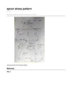


© Copyright 2026