
DP-CL18
ORDER No.KM60503633CE
G0
Color Laser Printer
DP-CL18
© 2005 Panasonic Communications Co., Ltd. All
rights reserved. Unauthorized copying and
distribution is a violation of law.
DP-CL18
2
DP-CL18
CONTENTS
Page
1 Introduction
Page
5
6.10. ENG Serial Number Item Menu
80
1.1. Specifications
5
6.11. Controller Setting Item Menu
81
1.2. Options, Accessories and Supplies
7
6.12. Panel Test Item Menu
82
1.3. Printer Panel
8
6.13. Engine Test Item Menu
83
1.4. External View
10
6.14. Color Correction Item Menu
93
1.5. Main Components Layout
11
6.15. Flag Setting Item Menu
93
1.6. PCB, Switches and Sensors Identification
13
6.16. Printing Network Configuration Report
94
2 About Lead Free Solder
7 Mechanical Function
15
95
2.1. Suggested PbF Solder
15
7.1. Drive Mechanism General Description
2.2. How to recognize that PbF Free solder is used
16
7.2. Accumulator Tension Unit (ATU) Drive Mechanism
3 Installation, Setup, and Repacking
21
7.3. Print Process
3.1. Installation Requirements
21
3.2. Setup
22
8.1. Fuser Unit
116
3.3. Repacking
24
8.2. Accumulator Unit (Acc. Unit)
117
4 User Mode Operation
30
8.3. Front Door Cover and STR (Second Transfer Roller) Bias
8 Removal and Replacement Procedures
95
98
108
116
4.1. User Mode Printer Panel Operation
30
4.2. User Mode Main Menu
32
8.4. Right Cover
119
4.3. Check then Print Selection 1 Menu
33
8.5. Rear, Left and Top Covers
119
4.4. Memory Print Item Menu
34
8.6. Color Registration Sensor
122
4.5. Confidential Print Selection 1 Menu
35
8.7. Engine Control Board, Toner Cartridge Holder, Cartridge
4.6. System Information Item Menu
36
4.7. Color Calibration Item Menu
37
4.8. Maintenance Item Menu
38
Assembly
117
Drive Unit, Paper Pickup Motor, Main Drive Unit, Bias Unit,
Fan Motor and Fan Motor Duct
123
8.8. LSU (Laser Scanning Unit)
133
8.9. Paper Exit
133
4.9. Tray Item Menu
39
4.10. Print Item Menu
41
8.10. IH (Inductive Heater) Unit
137
4.11. PCL Item Menu
42
8.11. Paper Feed Unit
140
4.12. PostScript Item Menu
43
8.12. Power Supply Unit (Power Supply Board and IH Power
4.13. N/W Protocol Setup Item Menu
44
4.14. Receive Setting Item Menu
46
8.13. Main Control Board
146
4.15. Adjust to Media Item Menu
47
8.14. High Voltage Board and Reg. Thermistor Sensor
147
4.16. System Item Menu
48
8.15. Accumulator Tension Unit
148
4.17. Mono Page Detect Item Menu
48
8.16. Print Cartridge Unit Holder
152
5 HDD Maintenance Mode Operation
49
8.17. Fuser Fan Motor
153
5.1. HDD Maintenance Mode Operation
49
8.18. Front Door Open Detection and Right Cover Open
5.2. HDD Maintenance Mode Menu Table
50
5.3. HDD Maintenance Mode Main Menu
51
5.4. HDD Information Item Menu
52
5.5. Check Disk Item Menu
53
5.6. Quick Format Item Menu
5.7. HDD Format Item Menu
5.8. HDD Deletion Item Menu
55
9.1. Block Diagram
161
56
9.2. Connection Diagram
163
6 Service Mode Operation
Board)
Detection Switches
144
153
8.19. MPT (Multipurpose Print Tray) Home Position Sensor and
MPT Paper Detection Sensor Boards
154
8.20. Waste Toner Cartridge Full Sensor
154
54
8.21. Standard Paper Cassette
155
55
9 Block and Connection Diagrams
161
6.1. Service Mode Control Panel Operation
56
10 Electrical Circuit General Description
6.2. Service Mode Menu Table
57
10.1. General Description
165
6.3. Service Main Menu
65
10.2. Explanation of Connector
169
6.4. Print Report Item Menu
66
6.5. Position Setting Item Menu
75
11.1. Print Position Calibration
198
6.6. STR Setting Item Menu
76
11.2. Color Density Adjustment
199
6.7. DEV. Bias Item Menu
77
11.3. Skew Adjustment
207
6.8. FSR Temp. Setting Item Menu
78
6.9. Maintenance Item Menu
79
11 Adjustment
12 Preventative Maintenance
12.1. General
3
165
198
210
210
DP-CL18
12.2. Recommended Tools
210
14.1. Covers
287
12.3. Recommend Cleaning
210
14.2. Left Side Parts
290
12.4. Maintenance Tables
211
14.3. Right Side Parts
297
212
14.4. Front and Top Side Parts
301
13.1. Initial Troubleshooting Flowchart
212
14.5. Rear Side Parts (Power Supply, Main Control and High
13.2. Warning/Error Message
213
13.3. Jam and HDD Error
228
14.6. Cassette
310
13.4. Print Quality
240
14.7. Packing Material
313
13.5. Printer Error (Call Service)
256
14.8. Toner Cartridge Dummy Case
313
13.6. No Message
283
14.9. Print Cartridge Dummy Case
313
13.7. No Printing
284
13 Troubleshooting
14 Replacement Parts List with Lubrication Guide
Voltage Boards)
14.10. PbF Solder Service Part Number
287
4
307
314
DP-CL18
1 Introduction
1.1.
Specifications
5
DP-CL18
6
DP-CL18
1.2.
Options, Accessories and Supplies
Model No.
DQ-UR3K
DQ-UR3C
DQ-UR3M
DQ-UR3Y
DQ-UR4C
DQ-UR4M
DQ-UR4Y
DQ-UP3K
DQ-UP3C
DQ-FU3
DQ-BF3
DQ-BE3
DQ-BR3
DA-DS1
KX-CLAD1
KX-CLEM3
KX-CLEM4
KX-CLHD2
DA-MC2
Description
Black Toner Cartridge 6K
Cyan Toner Cartridge 6K
Magenta Toner Cartridge 6K
Yellow Toner Cartridge 6K
Cyan Toner Cartridge 3K
Magenta Toner Cartridge 3K
Yellow Toner Cartridge 3K
Black Print Cartridge
Color Print Cartridge
Fuser Unit
Waste Toner Cartridge
Accumulator Unit
Transfer Roller
Optional Paper Feeder
Automatic Duplex Unit
128MB DIMM
256MB DIMM
Hard Disk Drive
Upgrade Kit for DP-CL18 (PS3)
Average
Average
Average
Average
Average
Average
Average
Average
Average
Average
Average
Average
Average
Life
Life
Life
Life
Life
Life
Life
Life
Life
Life
Life
Life
Life
Remarks
(6,000 pages *1)
(6,000 pages *1)
(6,000 pages *1)
(6,000 pages *1)
(3,000 pages *1)
(3,000 pages *1)
(3,000 pages *1)
(15,000 pages *1)
(15,000 pages *1)
(100,000 pages *1)
(14,000 pages *1)
(100,000 pages *1)
(100,000 pages *1)
*1
The rated life expectancy of each consumable is based on printing under specific operating conditions such as page coverage
for a particular page size (5% coverage per color at 600 x 600 dpi resolution on A4 size paper). The actual consumable life will
vary depending on its use and other printing variables including page coverage, page size, media type, print resolution,
continues or intermittent printing, number of color planes, ambient temperature and humidity.
7
DP-CL18
1.3.
1.3.1.
Printer Panel
Panel Operation
8
DP-CL18
1.3.2.
LED Indicator
Three indicators show the following printer’s status:
On
Blink
Off
Indicator
Printer Status
Power
Printer is turned on.
Power
Printer is in the Power Save mode.
Power
Printer is turned off.
Printer is ready for printing.
(Printer warms up and starts printing automatically
when it receives print data.)
On Line
On Line
Ready
Printer is in the Off Line.
Error
Printer is in the normal condition.
Printer is not in error conditions.
Ready
Error
Ready
Error
Ready
Error
Printer is receiving data, printing or data remains in the memory.
Printer is in the Menu mode.
Printer recoverable errors (media jam, media empty, etc.)
has occurred.
An internal error (Call for Service Error) has occured.
9
DP-CL18
1.4.
External View
10
DP-CL18
1.5.
Main Components Layout
11
DP-CL18
12
DP-CL18
1.6.
PCB, Switches and Sensors Identification
Sensor/Switch/Board Name
Paper Size Detection
Toner Empty Sensor Board
Temp./Humidity Sensor Board
Paper Full Sensor Board
Description
For detecting the current selected paper size at the standard paper cassette.
For detecting whether the toner is low (or empty) or not.
For sensing the ambient temperature and humidity.
This board has the paper full sensor. The paper full sensor is for detecting whether the output
paper tray is full.
Toner Cartridge Access Cover Detection For detecting whether the toner cartridge access cover is closed. If the toner cartridge access
Switch
cover is opened, printing is not possible.
ADU Jam Detection Sensor Board
For detecting whether the paper is ejected from the ADU (Option Automatic Duplex Unit) within
the proper time.
ADU Detection Sensor Switch
For detecting whether the ADU is installed.
MPT Paper Detection Sensor Board
For detecting whether the paper is set on the MPT (multi-purpose paper tray).
MPT Home Position Sensor Board
For detecting the home position of the MPT pickup roller.
Paper Empty/Registration Sensor Board This board has the paper empty and registration sensors. The paper empty sensor is for
detecting whether the paper is set on the standard paper cassette. The registration sensor is for
detecting whether the sheet of paper arrived at the registration roller after being properly picked
and traveling through the paper feed rollers.
OPC Cam Home Position Sensor Board For detecting the home position of the OPC drum.
Acc. Cam Home Position Sensor Board For detecting the home position of the accumulator cam and controlling the printing process.
Front/Right Door Open Detection Switch For detecting whether the front door or right cover is opened.
13
DP-CL18
Sensor/Switch/Board Name
LSU Safety Interlock Switch
Description
When the front door or right cover is opened (or both are opened), the power that is supplied to
the laser diode drive circuit in the laser unit is shut off because this switch is opened
Front/Right Door Interlock Switch
When the front door or right cover is opened (or both are opened), the printing is not done
because this switch is opened.
Waste Toner Cartridge Full Sensor Board For detecting whether the waste toner cartridge is full.
Color Registration Sensor Board
For reading the Color Registration Check Pattern to calculate adjustment for the fine Color
Registration Adjustment.
14
DP-CL18
2 About Lead Free Solder
2.1.
Suggested PbF Solder
We recommend you to use the following solder when re-soldering component for repair. Before using other Pb free solder than the
following solder, be sure to confirm a solder maker you appoint has made license agreements to be required when using Pb free
solder legally.
Supplier: Senju Metal Industry Co., Ltd. (http://www.senju-m.co.jp)
Part Description in Senju: ECO SOLDER RMA02 P3 M705 Series
Note:
When the recommended PbF solder is not available at Senju Metal Industry Co., Ltd., see section 14.10 PbF Solder Service
Part Number.
15
DP-CL18
2.2.
2.2.1.
How to recognize that PbF Free solder is used
Main Control Board
(Top View)
Marked PbF
2.2.2.
ROM Board
(Top View)
Marked PbF
16
DP-CL18
2.2.3.
Engine Control Board
Marked PbF
2.2.4.
Paper Empty/Registration Sensor Board
Marked PbF
17
DP-CL18
2.2.5.
Multi-purpose (MPT) Paper Detection Sensor Board
2.2.6.
ADU Jam Detection Sensor Board
Marked PbF
2.2.7.
Paper Full Sensor Board
Marked PbF
2.2.8.
OPC Cam Home Sensor Board
Marked PbF
2.2.9.
Accumulator Cam Home Position Sensor Board
18
DP-CL18
2.2.10. Waste Toner Full Detection Board
Marked PbF
2.2.11. Toner Empty Sensor Board
Marked PbF
2.2.12. Multi-purpose (MPT) Home Position Sensor Board
Marked PbF
2.2.13. Color Registration Sensor Board
2.2.14. Exit FG Board
19
DP-CL18
2.2.15. LCD Board
Marked PbF
20
DP-CL18
3 Installation, Setup, and Repacking
3.1.
3.1.1.
Installation Requirements
Environment
1. Temperature Range :10 °C - 32.5 °C (50 °F - 90.5 °F) (Temperature fluctuation ± 10 °C per hour or less)
2. Humidity Range :20% RH - 80% RH (Humidity fluctuation ± 20 °C per hour or less)
3. Weight : Gross; Approx. 33 kg (72.77 lbs.), Net; Approx. 30 kg (66.15 lbs) excluding packing material
4. Place the unit on a stable, level surface.
5. Do not install the unit under the following conditions.
a. Extremely high or low temperature
b. Extremely high or low humidity
c. Direct exposure to sunlight
d. Areas of high dust concentration
e. Areas of poor ventilation
f. Areas exposed to chemical fumes
g. Areas with extreme vibration
h. Directly in air conditioning flow
3.1.2.
Minimum Space Requirements
1. Right : 33 cm (13")
2. Left : 11 cm (4.3")
3. Rear : 15 cm (5.9")
Note:
When you install a consumable component or replace it with a new one, additional space may be required.
21
DP-CL18
3.2.
Setup
3.2.1.
Removing the Packing Material
1. Remove the plastic bag from the printer.
2. Remove any adhesive tape.
Note:
Please do not throw away the packing materials. They may be required to ship or transport the printer. To provide optimum print
quality, the unit must be kept upright and level at all times.
3.2.2.
Installing the Toner Cartridge
1.Open the toner cartridge access cover
( toner door) and remove the sealing
tapes.
3.Insert the toner cartridges in the appropriately
labeled slots. From right to left, the order of the
color toner cartridges is Black (1), Cyan (2),
Magenta (3), Yellow (4).
(4) (3) (2) (1)
2.Open the plastic bags and take out the
toner cartridges. Shake the toner
cartridges several times.
4.Close the toner cartridge access cover ( toner
door).
22
DP-CL18
3.2.3.
Installing the Print Cartridge
1.Open the right cover (right side door).
6.Firmly push the color print cartridge
until it snaps into place.
• Store the protective tray, seal covers,
packing materials and cartons for
repacking in future.
2.Unlock and open the print cartridge
holder.
7.Repeat steps 4 - 6 for the black print
cartridge.
( )
3.Open the plastic bags and take out
the print cartridges.
4.Remove the seal covers.
Color print cartridge
1
4
2
3
Black print cartridge
2
1
Protective tray
( )
8.Install the waste toner cartridge (1)
and slide the green lever (2).
2
Note:
To prevent damage to the print cartridge,
• Do not touch the green drum surface.
• Do not expose to light for more than 45 sec.
• Do not expose to direct sunlight.
Green
drum
1
9.Close the print cartridge holder until it
clicks (1) and locks it (2).
5.Holding the color print cartridge with
the protective tray, match the arrow
marks ( ) then insert the color print
cartridge half way into the printer.
( )
2
2
1
10.Close the right side cover (door).
( )
Protective tray
23
DP-CL18
3.3.
Repacking
Prepare the unit before shipping.
Note:
It is highly recommended that users keep the original carton and All packing materials. Please follow these instructions when
moving the printer.
· Please use the original carton and all of the original packing material.
· Improper repacking of the printer may result in a charge to repair the unit or a cleaning charge to remove spilled toner.
· Since the printer uses dry toner, extreme care must be taken when handling. The printer should be handled in the upright
(vertical) position.
· Original carton and packing materials
· Newspaper or drop cloth
· Shipping tape and scissors
24
DP-CL18
6 Unlock the two levers (1) and open the print
cartridge holder (2).
1 Turn off the printer, remove the power code and all
interface cables.
2 Open the right cover (right side door).
1
2
1
7 Pull out the color print cartridge halfway and remove
it (2) while pressing the green stopper (1) on the left
side.
3 Slide the green lever for the waste toner cartridge to
the right (RELEASE).
2
1
Note:
To prevent damage to the print cartridge;
- Do not touch the green drum surface.
- Do not expose to light for more than 45 minutes.
- Do not expose to direct sunlight.
4 Remove the waste toner cartridge.
Be sure the green lever is in the RELEASE position so
that upper openings to waste toner cartridge are
completely closed.
5 Insert the waste toner cartridge into a plastic bag
and seal the end of the bag tightly.
25
DP-CL18
8
Close the PC shutter and wipe off any loose toner on
the color print cartridge using a toner vacuum. Do not
use a standard office vacuum; the toner will not be
retained by typical vacuum dust collectors.
Caution 1:
If replacing the upper seal cover though the
toner is on the color print cartridge, the toner
will be scattered when removing the upper
seal cover. The scattered toner may be
attached to the OPC drum and the poor print
quality will be caused.
11 Pull out the black print cartridge.
Caution 2:
If the print cartridge is wiped using a toner
vacuum when the PC shutter is opening, the
toner in the print cartridge is sucked and
charged. This charge is discharged to the
OPC drum and the OPC drum may be
damaged. Wipe off the toner on the print
cartridge using care that the PC shutter is
not opened.
PC Shutter
Move the PC shutter in
this arrow direction to
close the PC shutter.
9
Replace the protective tray (1), upper seal covers (2-4)
and protective caps (5).
Be sure the three sealing levers of the print cartridge
are exposed through the lower seal cover.
2
5
4
3
4
Lever
Note:
To prevent damage to the print cartridge;
- Do not touch the green drum surface.
- Do not expose to light for more than 45 minutes.
- Do not expose to direct sunlight.
12 Close the PC shutter and wipe off any loose toner on
the black print cartridge using a toner vacuum. Do
not use a standard office vacuum; the toner will not
be retained by typical vacuum dust collectors.
Caution 1:
If replacing the upper seal cover though the
toner is on the black print cartridge, the toner
will be scattered when removing the upper
seal cover. The scattered toner may be
attached to the OPC drum and the poor print
quality will be caused.
Caution 2:
If the print cartridge is wiped using a toner
vacuum when the PC shutter is opening, the
toner in the print cartridge is sucked and
charged. This charge is discharged to the
OPC drum and the OPC drum may be
damaged. Wipe off the toner on the print
cartridge using care that the PC shutter is
not opened.
1
Lower Seal Cover
10 Insert the color print cartridge into the black plastic
bag and seal the end of the bag tightly with adhesive
tape.
PC Shutter
Move the PC shutter in
this arrow direction to
close the PC shutter.
26
DP-CL18
13 Replace the protective tray (1), upper seal cover (2) 16 Remove the media from the multi-purpose tray.
and protective cap (3).
Push the multi-purpose tray (1) and close the tray
cover (2).
Be sure the sealing lever of the print cartridge is
exposed through the lower seal cover .
3
2
1
1
Lever
2
Lower Seal Cover
17 Pull the media tray (1) out of the printer. Remove the
media (2) from the media tray and install the tray pad
(3) into the media tray.
14 Insert the black print cartridge into the black plastic
bag and seal the end of the bag tightly with
adhesive tape.
3
2
1
15 Close the print cartridge holder [(1)-(2)] and lock it.
Close the right cover (3) (right side door).
18 Install the media tray into the printer.
19 Close (1) and insert (2) the paper support into the
printer.
1
2
1
2
2
3
Accumulator unit
Note:
Be sure the accumulator unit is kept in the printer.
20 Confirm all toner cartridges are completely installed
in the printer.
27
DP-CL18
If the hard disk drive option has been installed in the printer, confirm the hard disk
drive is fastened with two screws provided. If it is not installed, proceed to step 26.
21 Remove the two thumb screws from the main
control board.
24 Install the main control board back into the
printer, as shown.
22 Pull out the main control board while holding the
green handle.
25 Tighten the two thumb screws.
23 Reconfirm the hard disk drive is fastened with two
screws. If it is not fastened, fasten it with two
screws.
28
DP-CL18
26 Repack the printer in the original shipping box.
Make sure that you keep the printer upright and level when moving.
SAFETY CAUTION
The printer weighs about 30 K (66 lbs.).
It must be handled by two people.
(1) Place the printer in the plastic bag on the lower cushion and wrap the printer with the plastic bag.
(2) Place the middle on the lower cushion, upper cushion on the printer and middle cushion.
(3) Place the waste toner cartridge, black print cartridge and color print cartridge and accessory box on the
upper cushion.
Color print cartridge
Black print cartridge
Waste toner cartridge
Accessory Box
(4) Place the top carton and install the 4 joints.
1
2
29
3
DP-CL18
4 User Mode Operation
4.1.
4.1.1.
User Mode Printer Panel Operation
Panel Operation
30
DP-CL18
4.1.2.
LED Indicator
Three indicators show the following printer’s status:
On
Blink
Off
Indicator
Printer Status
Power
Printer is turned on.
Power
Printer is in the Power Save mode.
Power
Printer is turned off.
Printer is ready for printing.
(Printer warms up and starts printing automatically
when it receives print data.)
On Line
On Line
Ready
Printer is in the Off Line.
Error
Printer is in the normal condition.
Printer is not in error conditions.
Ready
Error
Ready
Error
Ready
Error
Printer is receiving data, printing or data remains in the memory.
Printer is in the Menu mode.
Printer recoverable errors (media jam, media empty, etc.)
has occurred.
An internal error (Call for Service Error) has occured.
31
DP-CL18
4.2.
User Mode Main Menu
This section covers the basic operation of this model.
1 Plug in the power cord and connect an interface cable to the laser printer.
2 Turn on the power switch. The LCD displays “Initializing”, then “Ready or Ready (PCM*)”
If the Optional Hard Disk Drive is installed, the LCD displays the “Initializing” and “HDD Accessing” alternately.
3 When Ready or Ready (PCM*) is displayed in the upper line of the LCD, press the Menu/Exit (Pause) button to enter the Menu Mode.
*: Print Count Manager is turned on.
The following chart shows all functions of MENU Mode that are displayed when selecting functions.
32
DP-CL18
4.3.
Check then Print Selection 1 Menu
33
DP-CL18
4.4.
Memory Print Item Menu
34
DP-CL18
4.5.
Confidential Print Selection 1 Menu
35
DP-CL18
4.6.
System Information Item Menu
36
DP-CL18
4.7.
Color Calibration Item Menu
37
DP-CL18
4.8.
Maintenance Item Menu
38
DP-CL18
4.9.
Tray Item Menu
39
DP-CL18
4.9.1.
Position Setting Selection 1 Menu
40
DP-CL18
4.10. Print Item Menu
41
DP-CL18
4.11. PCL Item Menu
42
DP-CL18
4.12. PostScript Item Menu
43
DP-CL18
4.13. N/W Protocol Setup Item Menu
44
DP-CL18
45
DP-CL18
4.14. Receive Setting Item Menu
46
DP-CL18
4.15. Adjust to Media Item Menu
47
DP-CL18
4.16. System Item Menu
4.17. Mono Page Detect Item Menu
48
DP-CL18
5 HDD Maintenance Mode Operation
5.1.
HDD Maintenance Mode Operation
The HDD Maintenance mode has the following functions:
1. Displaying information of printer’s hard disk drive
- Volume Label
- Total Size
- Free Size
2. Checking the printer’s hard disk drive
3. Formatting the printer’s hard disk drive
- Quick Format: Bad sectors are not checked.
- HDD Format (Physical Format): It will take more time than the Quick Format because bad sectors are checked.
- HDD Deletion:
This feature is used for disposing of a printer’s hard disk drive for security purposes. All sectors of the hard disk drive will be initialized.
(It will take about 2 hours for 40 GB HDD.)
The HDD Maintenance Mode is entered by turning on the power while pressing the Continue button until “Initializing...” is
displayed.
49
DP-CL18
5.2.
HDD Maintenance Mode Menu Table
The following table is shown when a hard disk drive is installed. If it is not installed, “HDD is not Installed” is displayed on the LCD
Panel.
50
DP-CL18
5.3.
HDD Maintenance Mode Main Menu
51
DP-CL18
5.4.
HDD Information Item Menu
52
DP-CL18
5.5.
Check Disk Item Menu
53
DP-CL18
5.6.
Quick Format Item Menu
54
DP-CL18
5.7.
HDD Format Item Menu
5.8.
HDD Deletion Item Menu
55
DP-CL18
6 Service Mode Operation
6.1.
6.1.1.
Service Mode Control Panel Operation
How to enter the Service Mode
To enter the “Service Mode”, turn on the power while pressing the
and
buttons at the same time, and keep the pressing
the
and
buttons until “Initializing” is displayed. The Service Mode will be activated. The Service Mode is accessible when
the Power Save is off. After warming up, “Service Mode” is displayed in the LCD. This service mode is canceled by turning off the
printer. The printer has a two-line, 40 character LCD (2 x 20 characters). The menus in the following Service Mode flowchart
(sections 6.3 ~ 6.15) are displayed in the lower line.
6.1.2.
How to print the Network Configuration Report
Turn on the power while pressing the Enter button and keep the pressing the Enter button until “Initializing...” is displayed. The
Network Configuration Report will be printed. When completing the printing the Network Configuration Report, the printer’s LCD will
display “Ready”. The printing examples are indicated in the section 6.16 “Printing Network Configuration Report”.
56
DP-CL18
6.2.
Service Mode Menu Table
57
DP-CL18
58
DP-CL18
59
DP-CL18
60
DP-CL18
61
DP-CL18
62
DP-CL18
63
DP-CL18
64
DP-CL18
6.3.
Service Main Menu
65
DP-CL18
6.4.
Print Report Item Menu
Menu Name
Service Report 1
Service Report 2
Configuration Page
NW Config. Page
ENG eeprom Dump
CONT eeprom Dump
Description
Information regarding JAMs, Service Error Log, etc. is printed.
Information regarding the life count values of consumables and basic setting of engine is printed.
General information regarding printer settings or configuration is printed.
General information regarding the basic setting regarding network configuration is printed.
Hex Dump of the engine board EEPROM is printed.
Hex Dump of the main control board EEPROM is printed.
66
DP-CL18
6.4.1.
Printing Example of Service Report 1
The following is an example of what is printed when performing the “Service Report 1” menu.
67
DP-CL18
6.4.2.
Printing Example of Service Report 2
The following is an example of what is printed when performing the “Service Report 2” menu.
68
DP-CL18
6.4.3.
Printing Example of Configuration Page
The following is an example of what is printed when performing the “Configuration Page” menu.
69
DP-CL18
70
DP-CL18
6.4.4.
Printing Example of ENG eeprom Dump
71
DP-CL18
6.4.5.
Printing Example of CONT eeprom Dump
72
DP-CL18
6.4.6.
Printing Example of NW Config. Page
The following is an example of what is printed when performing the “NW Config. Page” menu.
73
DP-CL18
74
DP-CL18
6.5.
Position Setting Item Menu
Menu Name
Top
Tray 1 Left
Tray 2 Left
Tray 3 Left
MPT Left
Duplex Left
Test Print
Description
This mode is used to adjust the top print position, primarily when moving the printer, installing the optional paper feeder,
replacing the laser scanning unit or replacing the engine board.
This mode is used to adjust the left print position of the printed media loaded in the Tray 1, primarily when moving the printer,
installing the optional paper feeder, replacing the laser scanning unit or replacing the engine board.
This mode is used to adjust the left print position of the printed media loaded in the Tray 2, primarily when moving the printer,
installing the optional paper feeder, replacing the laser scanning unit or replacing the engine board.
This mode is used to adjust the left print position of the printed media loaded in the Tray 3, primarily when moving the printer,
installing the optional paper feeder, replacing the laser scanning unit or replacing the engine board.
This mode is used to adjust the left print position of the printed media loaded in the multi-purpose tray, primarily when moving
the printer, installing the optional paper feeder, replacing the laser scanning unit or replacing the engine board.
This mode is used to adjust the left print position of the printed media on the back the page, primarily when moving the printer,
installing the optional paper feeder, replacing the laser scanning unit or replacing the engine board.
The lines to check the top, left and back side left print positions are printed.
75
DP-CL18
6.6.
STR Setting Item Menu
The following service menus are used to adjust the toner density for each media (Plain, Thin Paper, Transparency, Label, Coated
Paper, Thick Paper, Card Stock, Envelope, JP Postcard and JP Postcard 2nd).
76
DP-CL18
6.7.
DEV. Bias Item Menu
The following service menus are used to adjust the toner density for all color toner (Cyan, Magenta, Yellow, Black).
77
DP-CL18
6.8.
FSR Temp. Setting Item Menu
The following service menus are used to adjust the fusing temperature for each media (Plain, Thin, Transparency, Label, Coated
Paper, Thick, Card, Envelope, JP Postcard and JP Postcard 2nd.)
78
DP-CL18
6.9.
Maintenance Item Menu
Menu Name
New TC-C?
New TC-M?
New TC-Y?
New TC-K?
New AU?
New TR?
New FSR?
Error Counter Clr
JAM Error Log Clr
Service Err.Log Clr
Description
Cyan Toner Cartridge counter is reset.
Magenta Toner Cartridge counter is reset.
Yellow Toner Cartridge counter is reset.
Black Toner Cartridge counter is reset.
Accumulator Unit counter is reset.
Second Transfer Roller counter is reset
Fuser Unit counter is reset.
All counters, printed by the Print Report in the service mode, are reset.
All JAM Error Logs, printed by the Print Report in the service mode, are reset.
All Service Error Logs, printed by the Print Report in the service mode, are reset.
79
DP-CL18
6.10. ENG Serial Number Item Menu
The Engine Serial Number (eleven figures) is input using this menu.
80
DP-CL18
6.11. Controller Setting Item Menu
Menu Name
Country
Print Format
Language
PCL Symbol Set
Power Save Level
Description
Application area/country is set.
Default Paper Size is set.
Default Language is set.
Default Symbol Set is set.
Default Power Save Level is set.
81
DP-CL18
6.12. Panel Test Item Menu
This menu is used to check the LCD. Select the “Panel Test “and press the Enter button. Confirm that the LCD messages/patterns
shown in the following table are displayed.
82
DP-CL18
6.13. Engine Test Item Menu
83
DP-CL18
6.13.1. Solenoid TEST
84
DP-CL18
6.13.2. Regist Clutch TEST
85
DP-CL18
6.13.3. Motor TEST
86
DP-CL18
6.13.4. Paper Detect Sensor TEST
87
DP-CL18
6.13.5. Cassette Sensor Test
88
DP-CL18
6.13.6. Temp & Humidity Sensor
89
DP-CL18
6.13.7. WTC & Toner Sensor
90
DP-CL18
6.13.8. Door Sensor
91
DP-CL18
6.13.9. Other Sensor
92
DP-CL18
6.14. Color Correction Item Menu
6.15. Flag Setting Item Menu
If “Yes” is selected on this menu, the printer will be filled with toner about 5 minutes after turning on the printer the next time.
93
DP-CL18
6.16. Printing Network Configuration Report
The following is an example of what is printed when performing the Printing Network Configuration Report (refer to the section 6.1.2
“How to print the Network Configuration Report”.).
94
DP-CL18
7 Mechanical Function
7.1.
Drive Mechanism General Description
cartridges, accumulator unit (Acc Unit or AU), accumulator
tension unit (ATU), paper feed unit and fuser unit.
Three motors (CMY motor, BK motor, paper pickup motor)
supply drive to each mechanical block within the engine. The
CMY motor (DC servomotor) supplies drive to the color print
cartridge (CMY PC). The BK motor (DC servomotor) supplies
drive to the black print cartridge (Black PC), four color toner
The paper pickup motor (stepping motor) supplies drive to the
multi-purpose paper feeder and option Auto Duplex Unit (ADU).
95
DP-CL18
7.1.1.
CMY Motor Rotation Travel
(CMY Motor Rotation Travel)
Cyan Print Cartridge (OPC)
Cyan Print Cartridge (Developer)
Magenta Print Cartridge (OPC)
Magenta Print Cartridge (Developer)
Yellow Print Cartridge (OPC)
Yellow Print Cartridge (Developer)
(5)
(14)
(13)
(8)
(9)
(4)
(12)
(1)
(11)
(3)
(10)
(2)
(7)
(6)
CMY Motor
The CMY Motor Rotation is transmitted in the following number order :
(2)
(3)
(4)
(5)
To Yellow Print Cartridge (Developer)
To Yellow Print Cartridge (OPC)
(1)
(7)
(8)
(9)
To Magenta Print Cartridge (Developer)
To Magenta Print Cartridge (OPC)
(6)
(10)
(11)
(12)
(14)
(13)
To Cyan Print Cartridge (Developer)
To Cyan Print Cartridge (OPC)
96
DP-CL18
7.1.2.
BK Motor Rotation Travel
(BK Motor Rotation Travel)
The Motor Rotation is transmitted to the Toner Cartridge
Holder Unit through this gear.
The Motor Rotation is transmitted to the Black Print Cartridge
(Developer) through this gear.
The Motor Rotation is
transmitted to the Toner
Cartridge Drive Unit through
this gear.
The Motor Rotation is transmitted to the Black Print Cartridge
(OPC) through this gear.
The Motor Rotation is transmitted to the
fuser through this gear.
(12)
BK Changer Gear
with Solenoid
(15)
(11)
(10)
(9)
(20)
(17)
(24)
(16)
(26)
(22)
(8)
(18) (19)
(5)
(1)
(27)
(6)
(3)
(2)
The Motor Rotation is
transmitted
to
the
Accumulator Unit through
this gear.
BK Motor Gear
(BK Changer Gear Solenoid)
The BK Motor Rotation is transmitted in order the following numbers :
The rotation transmission to the black print cartridge
is controlled by the BK Changer Gear Solenoid.
When the BK Changer Gear Solenoid is turned on,
the BK clutch arm is unlatched from the Gear (A). As
a result, the BK motor rotation is not transmitted from
(18) to (19) ~ (21) and black print cartridge.
21
Gear (A)
(18)
(19)
(20)
20
19
18
BK Changer
Gear Solenoid
(17)
(7)
(4)
The Motor Rotation is transmitted to
the Accumulator Tension Unit and
Paper Feed Unit through this gear .
(16)
(13)
(21)
(23)
(25)
(14)
(21)
BK Clutch Arm
To Black Print Cartridge (Developer)
To Black Print Cartridge (OPC)
(3)
(1)
(2)
(8)
(4)
(9)
(5)
(10)
(6)
(7)
To Accumulator Unit
(12)
(13)
To Toner Cartridge Drive Unit
(14)
(15)
To Toner Cartridge Holder Unit
(11)
(25)
(22)
(23)
To Fuser Unit
(24)
(26)
97
(27)
To Accumulator Tension Unit
and Paper Feed Unit
DP-CL18
7.2.
Accumulator Tension Unit (ATU) Drive Mechanism
up accumulator belt slack”, “Contacting STR Roller to
Accumulator Belt”, “Selecting of FTR Roller”, “lifting up FTR
Roller” and “Waste Toner Cartridge Stirring” mechanisms.
The accumulator tension unit is for operating the function of
accumulator unit and depositing waste toner in the waste toner
cartridge.
The accumulator unit consists of “ATU Drive Clutch”, “Taking
Figure-1
(4)
Acc. Unit
(Accumulator Unit)
(1)
STR
(Second Transfer Roller)
(5)
(3)
(5) (6)
(2)
ATU
(Accumulator Tension Unit)
(1) ATU Drive Clutch
(2) Taking up Accumulator Belt Slack
(3) Contacting STR Roller to Accumulator Belt
(4) Lifting up FTR Roller
(5) Selecting of FTR Roller
(6) Waste Toner Cartridge Stirring
98
DP-CL18
7.2.1.
ATU Drive Clutch
The ATU drive clutch is used to turn on and off the rotation from the BK motor to the cam shaft. See the following figure-1. The ATU
drive clutch consists of the cam ratchet, cam ratchet wheel, cam ratchet wheel gear, 4 planetary gears and accumulator cam
switching solenoid. The rotation from the BK motor is transmitted to the cam ratchet wheel or cam ratchet wheel gear through the
double teeth gear and 4 planetary gears.
In standby mode, the cam ratchet wheel cannot rotate because hook (A) of the cam ratchet engages with the detent of the cam
ratchet wheel, and the cam ratchet wheel gear is free to rotate because the hook (B) is not engaged with the teeth of the cam
ratchet wheel gear. With this mechanism, the rotation from the BK motor is transmitted to the cam ratchet wheel gear and rotates
in the arrow (C) direction.
When the accumulator switching solenoid is turned on for a predetermined time (150 ~ 200 msec) to perform the printing process,
the hook (B) moves in the arrow (B) direction and is engaged with the teeth of cam ratchet wheel gear. The rotation of the cam
ratchet wheel gear is stopped, then the hook (A) moves in the arrow (A) direction and is released from the detent of the cam ratchet
wheel. As a result, the cam ratchet wheel is free and the cam ratchet wheel is rotated in the arrow (D) by the rotation transmitted
from the BK motor through the double teeth gear and 4 planetary gears. After this, the hook (A) engages with the detent (B) and
the cam ratchet wheel is locked by hook (A). The rotation from the BK motor is transmitted to the cam ratchet wheel gear and is
not transmitted to the cam shaft.
After hook (A) engages detent (C) and detent (D) the same way, hook (A) engages detent (A) again.
99
DP-CL18
There are 4 statuses of the accumulator tension unit for controlling the printing process. These 4 statuses are set by the 4 detents
of the cam ratchet wheel.
· Accumulator Belt Cleaning Position:
When the hook (A) engages with the detent (B), the slack in the accumulator belt is taken up by the “Accumulator belt slack”
mechanism. The cleaning of the accumulator belt is done.
· Toner Transfer Position:
When the hook (A) engages with the detent (C), the FTR roller(s) is (are) raised and come in contact with the accumulator belt
by the “Lift FTR Roller” mechanism for transferring the toner from the OPC drum to the accumulator belt, and the STR roller is
engaged with the accumulator belt by the “STR Roller to Accumulator Belt” mechanism for transferring the toner to the paper.
· FTR Roller Release Position:
When the hook (A) engages with the detent (D), the FTR bias roller(s) is (are) released from the accumulator belt by the “Lift
FTR Roller” mechanism.
· Home Position:
When the hook (A) engages with the detent (A), the tension is released in the accumulator belt and the STR roller is removed
from the accumulator belt.
The accumulator cam home position sensor and sensor tab are for detecting whether the status of the accumulator tension unit is
shifted from one position to next within predetermined time or not. if the status of the accumulator tension unit is not shifted to the
next position within the predetermined time, Error Message “Printer Error 24” is displayed on the LCD display. The following chart
figure-4 indicates the relation between the sensor tab and accumulator cam home position sensor at each position.
100
DP-CL18
7.2.2.
Taking up Accumulator Belt Slack
Taking up accumulator belt slack is performed by the tension cam link, cam shaft, STR cam in the accumulator tension unit and
4 levers (A) - (D), belt tension roller in the accumulator unit. The following indicates the location of these parts (tension cam link,
cam shaft, etc.).
The tension cam link in the accumulator tension unit is engaged with the lever (A) in the accumulator unit [Part (E)]. When the cam
shaft start to rotate, the tension cam link moves to the arrow (2a) direction by the movement of STR cam linked with the cam shaft.
This movement is transferred to the lever (D) through the levers (B) - (C). The belt tension roller linked with the lever (D) moves to
the arrow (6) direction. This movement takes up the slack in the accumulator belt.
101
DP-CL18
7.2.3.
Contact STR Roller to Accumulator Belt
The STR roller is in contact with the accumulator belt or released from the accumulator belt by the STR release lever linked with
the STR cam in the accumulator tension unit. The following indicates the STR cam, cam shaft and STR release lever in the
accumulator tension unit.
When the accumulator tension unit is in the Home Position, the STR roller is released from the accumulator belt because the top
end of STR release lever pushes the STR roller holder in the arrow (A) direction. When the cam shaft rotates, the cam rotates in
the arrow (B) direction. When the cam shaft rotates 180° (the status of accumulator tension unit is in the “Toner Transfer Position”),
the STR tension spring moves the STR roller supported by the STR roller holder in the arrow (C) direction, the gap (A) decreases
between the part (A) and surface of cam. As a result, the STR roller moves in contact with the accumulator belt. This contact is held
until the cam shaft (cam) rotates 270° (The FTR Roller Release Position). When the cam shaft rotates 90° (the status of
accumulator tension unit returns to the Home Position), the cam moves the STR release lever in the arrow (A) direction and
releases the STR roller from the accumulator belt.
102
DP-CL18
7.2.4.
Lifting up FTR Roller
The FTR roller(s) is (are) contacted to the accumulator belt or released from the accumulator belt by the “FTR Roller Lifting Up”
mechanism consists of the FTR lift levers, FTR cams, cam shaft, etc.,. The following indicates the FTR lift levers, FTR cams, cam
shaft and FTR cam slider in the accumulator tension unit.
The FTR cam slider is engaged with the projections (C)-(D) in the accumulator tension unit. The projection (C) on the FTR lift lever
moves to the arrow (E1) direction by the FTR cam rotation. This projection (C) movement moves the FTR cam slider to the arrow
(E2) direction. When the FTR cam slider moves to the (1) direction of arrow (E2), the FTR roller in the accumulator unit contacts
with the accumulator belt. Regarding the detail information, refer to the next section “FTR Roller Lift Mechanism”. This model has
4 FTR rollers (cyan, magenta, yellow and black) The changer solenoid, changer lever and FTR cam slider are used for selecting
FTR rollers. Normally (when the changer solenoid is turned off), the FTR roller for black is selected. When the changer solenoid
is turned on, the changer lever moves to the arrow (F1) direction. As a result, the FTR cam slider moves to the arrow (F2) direction.
All FTR rollers (cyan, magenta, yellow and black) are selected, and contacted with the accumulator belt when the FTR cam slider
moves to the (1) direction of arrow (E2).
103
DP-CL18
7.2.4.1.
FTR Roller Lift Mechanism
The “FTR roller lift” is performed by the FTR cam slider in the accumulator tension unit, FTR roller lift lever, lift arm, spring and FTR
roller support lever. The following indicates the FTR roller lift lever, lift arm, spring, etc., in the accumulator unit.
<FTR Roller Lift Mechanism>
The FTR cam slider in the accumulator tension unit moves the FTR roller lift lever to the arrow (1) direction. This movement turns
the lift arm to the arrow (2) direction. The lift arm lifts up the FTR roller through a spring and the FTR roller contacts to the
accumulator belt.
104
DP-CL18
7.2.5.
Selecting of FTR Roller
There are four FTR rollers, three colors (yellow, magenta, cyan) and one for black. The changer solenoid is for selecting these FTR
rollers. When turning on the changer solenoid, the changer lever moves in the arrow (1) direction. The pin on the changer lever
moves the FTR cam slider in the same direction [arrow (2)]. This movement moves the FTR roller lift levers (see previous section
“FTR Roller Lift Mechanism”) in the accumulator.
When monochrome printing, the part (B) is engaged with the projection (B) on the black FTR roller lift lever. The black FTR roller
lift lever only moves in the Arrow (B) direction and black FTR rollers are contacted with the accumulator belt.
When color printing, the changer solenoid is turned on, moving the FTR cam slider in the arrow (A) direction. The projection (A) is
engaged with the part (B). When the FTR cam slider moves to the Arrow (B) direction, the CMY and black FTR roller lift levers move
to the Arrow (B) at the same time. As a result, the FTR rollers for color (yellow, magenta, cyan) and black are in contact with the
accumulator belt at the same time.
105
DP-CL18
7.2.6.
Waste Toner Cartridge Stirring
The waste toner cartridge is engaged with the WTC drive cam as shown below. The WTC drive cam is fixed to the cam shaft in
the accumulator tension unit. The WTC drive cam is rotating in the arrow (A) direction by the cam shaft. When the cam shaft rotates
one full turn, the WTC drive cam rotates 4 full turns. This rotation moves the waste toner cartridge in the arrow (B) direction, stirring
the toner in the waste toner cartridge. By this shuttling movement of the waste toner cartridge, the toner falls to the bottom of waste
toner cartridge.
106
DP-CL18
7.2.7.
Timing Chart
The following chart indicates the timing to the movement of accumulator tension unit.
107
DP-CL18
7.3.
Print Process
This Laser Printer creates an image on paper using a technique called laser electrophotography. The printer uses the
electrographic process known as Discharged Area Development, or “write black”. In this process, a digitally modulated laser scans
laterally across a rotating OPC (Organic Photo Conductive) drum that has been negatively charged. Wherever the OPC drum is
exposed by laser beam, the image is written and toner is transferred.
To generate a color image, the OPC drum suitably rotate to the image length, one for each primary color and black. During each
successive pass, the laser exposes the portions of OPC drum that correspond to the primary color’s component of the image.
Toner is attracted to the laser-exposed portions of the OPC drum.
As each color layer is developed on the each OPC drum, they are transferred to the accumulator belt until all four color layers
eventually reside one on top of the other on the accumulator belt. At this point, a sheet of paper is advanced under the accumulator
belt and the toner is transferred to the sheet of paper. The paper advances to the fuser, where heat and pressure permanently bond
the toner to the paper. From the fuser, the paper is driven to the output tray.
A cleaning blade scrapes residual toner from the OPC drum before the next primary color toner is applied to the OPC drum. This
prevents contamination of the next color layer. The cleaning blade is in constant contact with the OPC drum.
An accumulator belt cleaner scrapes residual toner from the accumulator belt. This prevents “ghosting “of the next print. The blade
only comes in contact with the belt after the accumulated toner layers are transferred to the sheet of paper
108
DP-CL18
7.3.1.
Charging
The charging roller, comes in contact with the OPC drum surface and charged to approximately -1100 volts, and ensures a uniform
negative potential of approximately -500 ~ 550 volts on the OPC drum surface by the charging roller, depending on the selected
dot per inch printing and ambient temperature.
7.3.2.
7.3.2.1.
Laser Exposure and Scanning
Laser Exposure
As the OPC drum rotates, the uniformly charged OPC drum is exposed by the modulated laser beam. The vertically-moving OPC
drum passes in front of horizontally scanning laser beam, and the negative charge on the OPC drum surface are neutralized by the
laser beam. This forms a latent image.
Laser output power is either approximately 0.25 mW or 0.4 mW on the OPC drum surface, depending on whether the printer is
printing in 1200 dots per inch (dpi) mode or 600 dpi mode. The laser exposure, the negative potential on the OPC drum varies from
approximately -500 ~ 550 volts (unexposed) to -50 volts (fully exposed).
7.3.2.2.
Laser Scanning
A laser diode generates the laser beam, and lenses and mirror in the laser scanner direct the beam to the OPC drum. The beam
is made parallel by the collimator lens and is directed at the rotating polygonal mirror, attached with the polygon motor. The beam
is made parallel by the collimator lens and is directed at the rotating polygon mirror. The polygon mirror rotates at a constant
revolutions approximately 18,000 per minute. This transforms the beam into a horizontally scanning beam, which is directed
through the primary lens, altering the beam’s angular rotation motion into a constant horizontal motion. The toric correction lens
corrects the beam for any vertical misregistration. Next, the beam reflects off of a mirror and passes through a window where it
scans across the rotating OPC drum. At the beginning of each horizontal sweep, the horizontal sync mirror deflects the laser beam
to the horizontal sync sensor. This informs the engine control board that the laser beam is beginning its horizontal sweep and that
it can begin to modulate the signal with the data to be printed on that line of the image.
109
DP-CL18
7.3.3.
Developing
As the OPC drum continues to rotate, it passes by the developer roller. The developer roller is charged to a potential approximately
-200 volts (350 VAC p-p). Toner is attracted to the exposed portions of the OPC drum in reverse proportion to the negative charge.
The greatest amount of toner is transferred to the most positive potential. The developer roller rotates at 1.33 times the speed of
the OPC drum to ensure a constant supply of toner.
Inside each developer is a toner supply roller that rotates in the opposite direction from the developer roller. This supplies a layer
of toner onto the developer roller. The doctor blade smooth and evenly distributes the toner on the developer roller. Gear-driven
paddle churn the toner and keep it fluidized and moving towards the developer roller.
7.3.4.
Toner Transfer to the Accumulator Belt
As the OPC drum rotates, in contact with the accumulator belt, which is rotating at the same speed. Located under the accumulator
belt at the contact point with the OPC drum, the first bias transfer roller carries a charge approximately +700 volts (FTR voltage).
This strong potential attracts and holds the toner from the OPC drum to the accumulator belt. The four color layers create while the
accumulator belt makes one complete rotation.
Any toner remaining on the OPC drum after the transfer to the accumulator belt is scraped off by the OPC drum cleaning blade,
which is always in contact with the OPC drum. This leaves the OPC drum clean for the next layer of toner to be transferred from
the developing roller into the developer.
110
DP-CL18
7.3.5.
Paper Pickup
The cam-shaped pickup rollers are driven by the BK (black print cartridge) drive motor and force a sheet between the paper feed
rollers. The pickup roller completes only one rotation to pick a sheet of media from the paper cassette. This will push the sheet of
paper to the paper feed rollers but does not pick a second sheet. Alternately, depending on the user’s selection, media may be
picked from the multi-purpose tray. The MPT tray pickup roller is driven by the MPT paper pickup motor and feeds a sheet of media
or an envelope into the registration roller.
The paper feed rollers advance the sheet of paper to the registration roller. The paper is driven lightly against the stationary
registration rollers to create a slight buckle in the paper, aligning the sheet of paper. At this point, the paper remains stationary
(since the registration roller clutch in the paper feed unit is not yet energized) until the image is ready to be printed on the paper.
The registration sensor detects whether the sheet of paper arrived at the registration roller after being properly picked and traveling
through the paper feed rollers.
The paper feed unit has the standard paper cassette paper empty and registration sensors. The standard paper cassette has the
MPT paper empty sensor for multi-purpose tray and the paper size detection levers. The standard paper cassette paper empty
sensor detects whether the paper is set in the standard paper cassette. The paper size detection levers are used for detecting
paper size and whether the standard paper cassette is installed in the printer. The MPT paper empty sensor detects whether the
paper is set in the MPT tray.
111
DP-CL18
7.3.6.
Toner Transfer to Paper
Once all four layers of toner reside up on the accumulator belt, the registration roller clutch is energized to advance a sheet of paper
(which has already been picked) to the second bias transfer roller. The toner image on the rotating accumulator and the paper that
is being fed into the image unit are synchronized for proper alignment. The leading edge of toner image on the accumulator belt
is aligned 4 mm from the leading edge of the paper. A strong positive voltage in the second bias transfer roller attracts the toner
from the accumulator belt to the paper. The second bias transfer roller voltage is approximately +1400 volts. This voltage varies
depending on the ambient temperature, humidity, print speed and media being printed upon. The paper (or transparency film)
advances at the same speed as the accumulator belt.
As the toner is being transferred to the paper, the accumulator belt cleaning blade is activated. This blade scrapes any remaining
traces of toner from the accumulator belt prior to the next image transfer. The scraped toner is discharged to the waste toner
cartridge by the spiral paddle shaft.
112
DP-CL18
7.3.7.
Fusing
After toner image has been applied to the paper, it passes through the fuser. When the BK motor starts to rotate, the IH coil is
turned on, heating the heat roller. As a result, the fuser belt, contacted with the heat roller surface, is heated by the heat roller. A
heated fuser belt melts the toner and pressure drives it into the paper. The melted toner bonds to the paper. After fusing, the paper
advances to the output tray. When the printer is idle, the IH coil is turned off and the fuser belt is not heated. At the 600 dpi printing
mode, the fuser belt is set to approximately 175°C. This fuser belt temperature varies depending on 1200 dpi printing mode, thick
paper printing mode, transparency printing mode, etc. The fuser unit has the paper ejection sensor, which detects the sheet of
paper as it leaves the fuser.
113
DP-CL18
7.3.8.
7.3.8.1.
Paper Exit and Paper Switchback
Normal Printing Mode (Not Duplex Printing Mode)
( Normal Printing Mode )
Rotation Switching Gear - A
( Rotation of this Gear is locked
because the Switching Lever engages. )
Paper Exit Roller
Switching
Lever
( To Paper Tray )
Switchback
Solenoid
Double Teeth
Gear
( From Fuser Unit )
After fusing, paper is fed to the output tray by the paper exit roller. Rotation from the BK motor is transmitted to the double teeth
gear. The rotation of double teeth gear is transmitted to the paper exit roller gear through intermediate gears in order of numbers
(1 - 8). The arrows indicate the rotation direction of each gear.
The Paper is ejected face down and stored in the output tray. The paper full sensor detects whether the paper output tray is full,
and if the tray is full, the message “Output Tray Full“is displayed on the LCD panel.
114
DP-CL18
7.3.8.2.
Duplex Printing Mode (Paper Switchback)
(Figure-1)
(Duplex Mode)
(Figure-2)
Rotation Switching Gear - A
( Rotation of this Gear is locked. )
Paper Exit Roller Switchback Pinch
Roller
Paper Path
Switching Guide
Switching
Lever
( To Paper Tray )
Arrow (A)
Switchback
Solenoid
Arrow (B)
Rotation Switching
Gear - B
( Rotation of this Gear
is locked. )
Paper Guides
Double Teeth
Gear
Double Teeth
Gear
( From Fuser Unit )
( To Auto Duplex Rollers )
The switchback solenoid is turned on by the time the top edge of paper passes by the paper jam sensor on the fuser unit. The
switching lever engages with the switching gear-B, and the rotation of rotation switching gear-B is locked. As a result, the rotation
from the BK motor is transmitted to the paper exit roller in order of numbers (1 - 8) through the double teeth gear. The arrows
indicate the rotation direction of each gears.
Also, the switching lever moves the paper path switching guide in the direction of arrow (A) as shown in the figure-1. This advances
the sheet of paper between the paper exit roller and switchback pinch roller. The paper is fed to the output tray by the paper exit
roller and pinch roller. At the proper time, the switchback solenoid is turned off, which returns the switching lever to the home
position. The rotation switching gear is locked by the switching lever, and the rotation from the BK motor is transmitted to the paper
exit roller in order of numbers (1 - 8) through the double teeth gear. As a result, the paper exit roller rotates in the reverse direction.
The paper path switching guide also is moved in the direction of arrow (B) (see figure-2) and returns to the home position. The
paper is fed to the auto duplex rollers in the optional Auto Duplex Unit through the paper guides along the paper path switching
guide. Further, the paper is fed to the registration roller by the auto duplex rollers and advanced to the fuser unit. After fusing, the
paper arrives the paper exit roller and is fed to the output tray by the paper exit roller.
115
DP-CL18
8 Removal and Replacement Procedures
in the IH coil, IH cable, thermostat cables and
thermostats. The nuts, screws and fasten terminals
connect the IH cable to the IH coil and thermostats. For
protection from fire, smoke and other hazard, don’t
loosen or remove any component on (from) the IH coil
unit.
Before performing the following steps, unplug the AC
power cord, then remove the 4 toner cartridges (cyan,
magenta, yellow and black), 2 print cartridges (black and color),
waste toner cartridge and standard paper cassette from the
printer.
Caution: Don’t loosen or remove any component (nuts,
screws, fasten terminals, etc.) on (from) the IH coil unit.
A large current (approx. 12Arms: 100V AC Power) flows
8.1.
Fuser Unit
Caution:
1. The fuser is hot. To avoid personal injury, wait 1 hour for fuser to cool after turning the power off, and then service it.
2. When replacing parts, use only the manufacturer’s specified components.
3. After servicing, be sure to restore the lead dress, insulation barriers, insulation papers, shields, etc.
(1)
Open the front door.
(2)
Disconnect the fuser connector from the printer.
(3)
Move the 2 fuser lock green tabs in the arrow directions to
unlatch the fuser unit.
(4)
Remove the fuser unit.
116
DP-CL18
8.2.
Accumulator Unit (Acc. Unit)
(1)
Open the right cover.
(2)
Loosen the 2 Acc. unit lock screws.
(3)
Slide out the Acc. unit from the printer with care to prevent
damage to accumulator belt.
8.3.
8.3.1.
Front Door Cover and STR (Second Transfer Roller) Bias Assembly
Front Door with STR Bias
(1)
Remove the left and right front door axes by releasing the
hooks.
(2)
Release the plastic belt and front support lever from the
front door.
(3)
Remove the front door.
117
DP-CL18
8.3.2.
STR (Second Transfer Roller) Unit
(1)
Release the STR roller cover by moving it in the arrow (A)
direction, then remove a STR Roller Assembly.
(2)
Remove the 4 screws while pushing the STR holder in the
arrow (A) direction and STR Unit from the front door cover.
(3)
Remove 4 plastic washers and 2 STR bushings from the
STR hinge shaft.
(4)
Slide out the STR hinge shaft from STR unit.
(5)
Separate the STR holder assembly from the STR frame
base assembly.
(6)
If necessary, remove the STR roller holders (1 screw), STR
springs, STR cover assembly, etc.
118
DP-CL18
8.4.
Right Cover
(1)
Release the 2 hooks of the cartridge lever A.
(2)
Release the plastic strap from the right cover.
(3)
Remove the right cover while releasing the 3 hinges and
hook from the printer chassis.
8.5.
8.5.1.
Rear, Left and Top Covers
Rear Cover
(1)
Remove the 2 main control board screws.
(2)
If necessary, remove the main control board.
119
DP-CL18
(3)
Remove the 2 screws.
(4)
Release the 5 hooks, using a small flat blade screw driver.
(5)
Remove the rear cover.
(6)
If necessary, remove the cassette cover and cable cover
from the rear cover.
8.5.2.
Left Cover
(1)
Remove the screws (2).
(2)
Release the openings from the 2 projections on the bottom
side of the printer while removing the left cover with the
toner cartridge access cover while releasing the 3 hooks.
120
DP-CL18
8.5.3.
Top Cover with LCD Panel
(1)
Release the 7 hooks to separate the LCD panel cover from
the top cover.
(2)
Separate the LCD panel cover with the LCD panel.
(3)
Disconnect the LCD cable and earth lead wire.
(4)
Release the 5 hooks (A) from the printer chassis.
(5)
Release the 2 hooks (B) from the printer chassis using a
small flat-blade screwdriver as shown in the Fig-1.
(6)
Separate the top cover from the chassis.
(7)
Disconnect the sensor cable from the top cover.
(8)
Remove the 6 screws and LCD panel.
(9)
Remove the 2 switch buttons and operation key.
121
DP-CL18
8.6.
Color Registration Sensor
Before performing the following steps, unplug AC cord, then remove the 4 toner cartridges (cyan, magenta, yellow and black),
waste toner cartridge and accumulator unit from the printer
(1)
Open the right cover.
(2)
Open the PC holder assembly.
(3)
Remove the color registration sensor board assembly (1
screw).
(4)
Disconnect the color registration sensor cable.
(5)
Separate the color registration sensor board from the
registration sensor holder (2 screws).
(6)
If necessary, remove the accumulator unit detector and
detector spring from the registration sensor holder.
Note:
When replacing the color registration sensor board, perform the “Mis-Reg.Tbl Reset” (see the section 6.14 “Color Correction
Item Menu”.) in the Service Mode to initialize the paprameter regarding the color registration.
122
DP-CL18
8.7.
8.7.1.
Engine Control Board, Toner Cartridge Holder, Cartridge Drive Unit,
Paper Pickup Motor, Main Drive Unit, Bias Unit, Fan Motor and Fan
Motor Duct
Engine Control and Temperature/Humidity Sensor Boards
Before performing the following steps, remove the left, top and rear covers.
(1)
Remove the engine board shield cover (8 screws).
(2)
Disconnect all cables from the engine control board.
(3)
If the main control board is installed, remove it.
(4)
Remove the engine board (7 screws).
(5)
Remove the engine board small (3 screws) and large
brackets [2 screws (A) and 4 screws (B)].
(6)
Remove the temperature/humidity sensor board.
123
DP-CL18
8.7.2.
Sub Fuser Fan and Sub Fuser Fan Duct
(1)
Remove the sub fuser fan (2 screws).
(2)
Disconnect the fan cable from the sub fuser fan.
(3)
Disconnect the CMY cable from the CMY motor.
(4)
Remove the sub fuser fan duct (2 screws).
8.7.3.
Toner Cartridge Drive Unit, Toner Cartridge Holder and Fuser Fan Duct Assembly
Caution:
In the toner cartridge holder assembly, the toner is stored. Remove or handle the toner cartridge holder assembly,
using care that toner is not spilled.
When removing the toner cartridge holder, first remove the toner cartridge drive unit to prevent the toner from spill,
then remove the toner cartridge holder.
(1)
Remove the 2 screws from the toner cartridge drive unit.
(2)
Separate the toner cartridge drive unit from the chassis.
(3)
Disconnect the toner empty sensor cable from the toner
cartridge drive unit.
(4)
Remove the PC guide (1 screw).
(5)
Remove the 2 screws from the toner cartridge holder
assembly.
(6)
Release the bundled cables by unlatching the cable
clamper on the toner cartridge holder assembly.
(7)
If necessary, cut the 3 plastic belts to release the toner
supply solenoid cable from the bundled cables.
(8)
Remove the toner cartridge holder assembly (see note).
Note:
The toner cartridge holder assembly is fixed to the chassis frame by 4 hooks. When removing the toner cartridge holder
assembly, move it in the arrow direction (1) and (2) to release the hooks from the chassis frame.
124
DP-CL18
8.7.4.
Paper Pickup Motor and Motor Bracket
(1)
Remove the 2 screws from the paper pickup motor.
(2)
If necessary, disconnect the connector CN22 on the engine
board, and cut the plastic belts which bundles the pickup
motor cable.
(3)
Remove the paper pickup motor from the paper pickup
motor bracket.
(4)
Remove the paper pickup motor bracket (4 screws).
(5)
The paper pickup drive gear can be removed from the
paper pickup motor bracket.
8.7.5.
Main Drive Unit
Important Notice: Handling of Main Drive Unit
125
DP-CL18
8.7.5.1.
Inner Cover, ADU Jam Detection Sensor Board and ADU Detection Sensor
1. Remove the inner cover (2 screws).
2. Disconnect the 2 connectors from the inner cover.
3. Remove the fuser earth plate (1 screw).
4. If necessary, remove the ADU jam detection sensor board
and ADU detection sensor.
8.7.5.2.
Main Drive Unit
1. Remove the 7 screws, securing the main drive unit.
2. If necessary, disconnect the 2 motor cables.
3. Separate the main drive unit from the chassis.
4. If necessary, disconnect the sensor cable from the main drive
unit.
Note: For easy re-installation of the main drive unit
When reinstalling the main drive unit, see the section
8.11 “Paper Feed Unit” and remove a clip and the
registration clutch from the paper feed unit.
After reinstalling the main drive unit, reinstalling the
registration clutch and a clip to the paper feed unit.
126
DP-CL18
8.7.5.3.
Main Drive Unit Disassembly
Notice: Installing CMY Motor
1. Remove the 4 screws (A) and 7 screws (B).
2. Remove the drive unit bracket (S), bushing and washer from
the drive unit.
3. If necessary, remove the Acc. GND spring (1 screw).
127
DP-CL18
1. Remove the feed idle gear, cam gear, PC (Print Cartridge)
idle gear (L), etc.
128
DP-CL18
1. Remove the CMY home lever, PC home spring and PC home
lever.
2. Remove the screw and OPC cam home position sensor
board.
1. Remove the 4 E-rings, 4 OPC Gears and 4 DEV. gear
assemblies.
Caution:
When exchanging the OPC Gears, the 4 OPC Gears must
be exchanged with new 4 gears with the same molding
number at the same time, or the poor printed quality may
be caused. Regarding to the molding number, the
molding number has been marked on the OPC Gear as
shown below (Figure-2).
2. Remove the fuser idle gear (1 E-ring).
129
DP-CL18
1. Remove the drive unit bracket (M) (4 screws).
130
DP-CL18
1. Remove the BK change gear with solenoid (1 screw).
2. Remove the CMY change gear, hopper change gear, etc.
1. Remove the screw and tension roller spring from the tension
roller bracket.
2. Remove the tension roller, Acc. (Accumulator Unit) pulley
gear, Acc. pulley gear flange, feed pulley gear, feed pulley
gear flange and feed belt.
131
DP-CL18
8.7.6.
Bias Unit
Before performing the following steps, remove the toner cartridge holder, toner cartridge drive unit, paper cassette drive motor
bracket, engine control board, sub fuser fan and main drive unit.
(1)
Disconnect the connectors CN2 and 3 on the high voltage
board (see section 8.14 “High Voltage Board and Reg.
Thermistor Senser”).
(2)
Remove the 1 screw from the earth plate.
(3)
Remove the 2 screws.
(4)
Remove the bias unit from the chassis.
8.7.7.
Power Supply Fan Motor and PSU Fan Motor Duct
Before performing the following steps, remove the toner cartridge holder, toner cartridge drive unit, paper cassette drive motor
bracket, engine control board, sub fuser fan and main drive unit.
(1)
Disconnect the fan motor cable from the fan motor.
(2)
Remove the fan motor (2 screws).
(3)
Remove the fan motor duct (2 screws).
(4)
If necessary, cut the plastic belt and separate the bundled
cable with the core from the fan motor duct.
132
DP-CL18
8.8.
LSU (Laser Scanning Unit)
Before performing the following steps, remove the left, top and rear covers (see section 8.5 “Rear, Left and Top Covers”).
(1)
Remove the LSU earth plate (4 screws).
(2)
Remove the 3 LSU screws from the LSU.
(3)
Separate the LSU from the printer.
(4)
Disconnect the 3 connectors from the LSU.
8.9.
Paper Exit
Before performing the following steps, remove the parts that are listed below:
1. all covers (see sections 8.3, 8.4 and 8.5)
2. Paper Pickup Motor Bracket (see section 8.7.4 “Paper Pickup Motor and Motor Bracket”)
(1)
Remove the 2 screws.
(2)
Disconnect the 2 connectors.
(3)
Remove the inner cover.
(4)
If necessary, remove the ADU (Automatic Duplex Unit)
detection sensor and ADU jam detection sensor board from
the inner cover.
133
DP-CL18
(5)
Remove 3 screws from the paper exit gear cover and 1
screw from the earth lead terminal.
(6)
Disconnect the connector CN26 on the engine board (see
section 8.7.1 “Engine Control and Temperature/Humidity
Sensor Boards “.
(7)
Remove the paper exit gear cover, gears and switching
lever from the chassis.
Note:
When reinstalling the gears on the paper exit gear
cover, see the following figure.
Caution:
The rotation switching gear (A) differs from the gear (B)
in the gears teeth shape. For reinstalling these gears
properly, see the following Figure-1.
134
DP-CL18
(8)
If the earth lead and screw are installed, remove the screw
to free the earth lead from the printer chassis.
(9)
Remove a screw from the paper exit sub assembly.
(10) Remove the paper exit roller and exit restraint levers by
moving it in the direction of arrow [(1), (2)].
(11) Remove the paper exit sub assembly.
135
DP-CL18
(12) Remove the paper full sensor and sensor lever spring.
(13) Remove the paper Full sensor board.
(14) Disconnect the cable from the sensor board.
(15) If necessary, disconnect the connector CN17 on the engine
control board.
8.9.1.
(1)
Disassembly of Paper Exit Sub Assembly
The pinch rollers (A), pinch rollers (B), pinch roller springs.
etc., can be removed from the paper exit roller holder.
136
DP-CL18
8.10. IH (Inductive Heater) Unit
Before performing the following steps, remove all covers and fuser unit.
Caution: Handling of the IH Unit
When turning on the IH unit, the current (approx. 12 Arms: 100V AC Power) flows in the IH unit. For safety, observe the
following:
If not necessary, don’t remove the plastic and metal covers from the IH unit.
Don’t loosen or remove any component (nuts, screws, fasten terminals, etc.) from the IH coil unit.
The current (approx. 12 Arms: 100V AC Power) flows in the IH coil unit. The following nuts and screws connect the IH cable
to the IH coil & thermostat cable. The thermostat cables are connected to the thermostats by the screws or the fasten terminals.
For protection from smoke, fire and other hazards, don’t loosen (or remove) any component (nuts, screws, fasten
terminals, etc.) on (from) the IH coil unit.
137
DP-CL18
(1)
Remove the interlock switch cover (3 screws).
(2)
Remove the IH cable shield cover while unlatching the hook
from the printer chassis using a flat-blade screw driver (1
screw and 1 hook) (see figure-1).
(3)
Remove the protect cover while pushing softly on the hook
using a small pin and moving it in the arrow direction (1
screw and 1 hook) (see figure-2).
(4)
Disconnect 2 connectors from the IH power supply board.
Note:
When rewiring the IH cable, the part with the white
color mark of the IH cable must be positioned between
the projections (A) and (B) as shown in the figure-3.
138
DP-CL18
(5)
Remove the IH harness cover (1 screw).
(6)
Remove the IH unit (1 screw and 1 washer) while pulling out
the IH harness cable through the opening.
Note:
The IH unit is engaged with the chassis frame by the
projection. When removing the IH unit from the chassis,
slide the IH unit in the arrow direction.
Caution 1:
When handling the IH unit, do not push or damage the
surface of the thermostat, or the thermostat may not
operate properly.
Caution 2:
When rewiring the IH cable or reinstalling the IH unit,
make sure that the IH unit moves smoothly inside [Arrow
(A) direction in the following figure].
(7)
Remove the IH shield cover while releasing the 2 hooks
from the chassis (1 screw).
139
DP-CL18
8.11. Paper Feed Unit
Before performing the following steps, remove the rear cover, left cover and front door.
(1)
Remove the clip.
(2)
Slide out the registration clutch and registration roller joint
gear.
Note:
When reinstalling the registration clutch, opening (A) of
registration clutch must be aligned with hook (B).
(3)
If necessary, disconnect the connector CN20 on the engine
board (see section 8.7.1 “Engine Control and
Temperature/Humidity Sensor Boards”).
(4)
Remove the 2 screws.
(5)
Disconnect the connectors CN18 and CN19 on the engine
board (see section 8.7.1 “Engine Control and
Temperature/Humidity Sensor Boards”).
(6)
Remove the paper feed unit while pulling out the cable
through the opening of chassis.
140
DP-CL18
Note: Wiring of Paper Feed Unit Cable
8.11.1. Paper Feed Unit Disassembly
(1)
Remove the pickup gear and inner gear (B) while unlatching
the gear hook.
(2)
The inner gear (A), outer gear and gear can be removed.
(3)
Remove the plastic washer and ratchet arm from the gear
bracket.
(4)
Remove the feed gear, idle gear and bushing.
(5)
Remove the screw and gear bracket.
(6)
Remove the pickup solenoid.
141
DP-CL18
(7)
Remove the bushing (B) from the pickup roller shaft.
(8)
Remove the bushing (A) while unlatching the bushing hook
from the pickup roller shaft.
(9)
Remove the 2 pickup roller assemblies from the pickup
roller shaft by sliding it in the arrow direction while
unlatching the hook from the groove of pickup roller shaft.
(10) Remove the pickup roller shaft with the 2 pins.
(11) Remove the 2 springs from the paper feed unit frame.
(12) Remove the registration roller, registration pinch roller and
2 bushings.
(13) Remove the paper empty/registration sensor board.
(14) Remove the registration sensor lever and lever spring.
(15) Remove the paper empty sensor lever.
(16) If necessary, remove the varistor.
142
DP-CL18
(17) The registration paper guide assembly is held in place by
the 2 support tabs (see Figure-1). While unlatching the
registration paper guide assembly from the support tabs,
remove it from the paper feed unit frame.
(18) Remove the 2 bushings from both end of paper feed roller,
then paper feed roller from the paper feed unit frame.
(19) Remove the registration paper guide and paper guide
spring from the registration paper guide assembly.
(20) After removing the 2 pinch roller spring, slide out the pinch
roller shaft in the arrow direction.
143
DP-CL18
8.12. Power Supply Unit (Power Supply Board and IH Power Board)
Before performing the following steps, remove the rear cover, right cover, left cover, top cover and accumulator unit.
(1)
Remove the screw from the protect cover.
(2)
Slide out the protect cover in the Arrow (B) direction while
pushing softly the hook using a small pin.
(3)
Disconnect the IH cable from the power supply board.
(4)
Remove the 13 screws and earth plate.
(5)
Slide out in the arrow (1) direction while disconnecting the
4 connectors.
144
DP-CL18
8.12.1. Power Supply Unit Disassembly
(1)
Separate the power supply shield cover from the power
supply base plate (10 screws).
(2)
Disconnect the 2 cables.
(3)
Remove 7 screws (B).
(4)
Remove the power supply board.
(5)
Remove the 5 screws (C), then the IH power supply board.
145
DP-CL18
8.13. Main Control Board
(1)
Remove the 2 screws.
(2)
Slide out the main control board with the ROM board.
8.13.1. Main Control Board Shield Covers
Before performing the following steps, remove all covers, power supply unit and engine board shield cover.
(1)
Remove the screw (A).
(2)
Remove the 4 screws (B).
(3)
Remove the LSU earth plate.
(4)
Remove the 5 screws (C), 2 screw (D) and release the
cables from the clamper, then remove the main control
board shield cover assembly.
(5)
Remove the 10 screws.
(6)
Separate the main board shield cover from the main board
shield base cover.
(7)
Remove the main board guide rail from the main board
shield base cover.
146
DP-CL18
8.14. High Voltage Board and Reg. Thermistor Sensor
Before performing the following steps, remove all covers, power supply unit, main control shield cover assembly and engine board
shield cover.
(1)
Remove the 2 screws (A) and 3 screws (B).
(2)
Separate the PC earth spring and high voltage unit
(consists of high voltage board, high voltage board shield
cover, etc.) from the chassis.
(3)
Disconnect the 4 connectors.
(4)
Separate the high voltage board from the high voltage
board shield cover (4 screws (C)).
147
DP-CL18
8.15. Accumulator Tension Unit
Before performing the following steps, remove rear cover, left cover, top cover, black print cartridge, color print cartridge and Acc
unit.
(1)
Open the right cover.
(2)
Open the print cartridge holder.
(3)
Remove the 2 screws.
(4)
Disconnect the connectors CN14, 24 and 25 on the engine
control board (see section 8.7.1 “Engine Control and
Temperature/Humidity Sensor Boards”.).
(5)
Remove the accumulator tension.
Note:
The accumulator cables are wired through the
opening of the chassis and connected to the 3
connectors CN14, 24 and 25 on the engine control
board. Remove the accumulator tension unit, using
care that the cables are not damaged.
Notice for reinstalling Acc. Tension Unit
148
DP-CL18
8.15.1. Accumulator Tension Unit Disassembly
(1)
Remove the FTR cam slider guide with damper (1 screw).
(2)
Remove the FTR cam slider (2 screws)
(3)
Remove the 5 springs.
(4)
Remove the 2 E-rings from both end of the sub shaft, and
slide out the sub shaft.
149
DP-CL18
(5)
Remove the plastic washer and E-ring from both end of the
cam shaft.
(6)
The WTC Drive Cam, WTC Outer Gear, WTC Planetary
Gear, etc., can be removed from the cam shaft.
(7)
Remove the cam shaft assembly.
150
DP-CL18
(8)
Remove the 2 E-rings from both ends of cam shaft.
(9)
The FTR (First Transfer Roller) Cam (R), FTR Cam Link
(R), etc., can be removed from the cam shaft.
Caution:
When reassembling the cam shaft, the 4 cams and
home tab must be aligned as shown below (Figure-2).
(10) The changer solenoid, changer lever, changer solenoid
spring, etc., can be removed from the accumulator tension
unit base easily.
151
DP-CL18
8.16. Print Cartridge Unit Holder
Before performing the following steps, remove rear cover, left and top covers.
When handling and servicing the Print Cartridge Unit Holder
· Do not handle part (A), or poor print quality will occur.
· Do not loosen or remove any screws on the print cartridge unit holder, or poor print quality may occur.
· When exchanging the print cartridge unit holder with a new part, a skew adjustment is needed. Refer to section 11.3 “Skew
Adjustment”.
(1)
Open the right cover.
(2)
Release the 2 tabs by moving it in the arrow direction.
(3)
Remove the 2 screws and print cartridge unit holder
assembly.
152
DP-CL18
8.17. Fuser Fan Motor
Before performing the following steps, remove rear, left and top covers.
(1)
Open the right cover.
(2)
Remove the screw and fuser fan motor from the chassis.
(3)
Remove the insulation sheet and then disconnect the fan
cable from the fan motor.
(4)
Disconnect the connector CN44 on the engine control
board (see section 8.7.1 “Engine Control and
Temperature/Humidity Sensor Boards”) and remove the
fuser fan cable from the chassis.
8.18. Front Door Open Detection and Right Cover Open Detection Switches
Before performing the following steps, remove the rear cover, right cover, top cover and front door.
(1)
Remove the 3 interlock cover screws and interlock cover.
(2)
Disconnect the cable (A), and remove the front door open
detection sensor.
(3)
If necessary, the cable (A) connector CN7 on the engine
control board (see section 8.7.1 “Engine Control and
Temperature/Humidity Sensor Boards”).
(4)
Disconnect the cable (B) from the power supply unit [see
section 8.12 “Power Supply Unit (Power Supply Board and
IH Power Board)].
(5)
Disconnect the cable (C) connector CN35 on the engine
control board (see section 8.7.1 “Engine Control and
Temperature/Humidity Sensor Boards”).
(6)
Remove the 2 screws and safety interlock switches from the
interlock switch bracket.
(7)
Remove the screw and interlock switch bracket.
153
DP-CL18
8.19.
MPT (Multipurpose Print Tray) Home Position Sensor and MPT Paper
Detection Sensor Boards
Before performing the following steps, remove the left, top cover and rear covers.
(1)
Remove the paper pickup motor bracket screw.
(2)
Remove the 2 screws from MPT sensor cover.
(3)
Remove the MPT sensor cover.
(4)
Remove the MPT home position sensor and MPT paper
detection sensor boards.
(5)
Disconnect the MPT home position sensor and MPT paper
detection sensor cables.
8.20. Waste Toner Cartridge Full Sensor
(1)
Open the right cover.
(2)
If the waste toner cartridge is installed, remove it.
(3)
Remove the 2 screws and waste toner cartridge right
holder.
(4)
Disconnect the cable from the waste toner cartridge full
sensor board.
154
DP-CL18
8.21. Standard Paper Cassette
(1)
Unlatch the hook from the delay pad holder assembly by
moving it in the arrow (1) direction.
(2)
Remove the delay pad holder assembly by turning it in the
arrow (2) direction.
(3)
Remove the delay pad holder assembly from the cassette.
155
DP-CL18
(4)
Slide out the pickup roller holder assembly from the pickup
roller shaft while unlatching the pickup roller hook from the
pickup roller shaft.
(5)
Remove the gear cover (2 screws), sub tray protector and
protector spring.
(6)
Remove the gear spacer, idle gear, roller position arm, MPT
cam gear, right cam and pin.
(7)
Remove the pickup roller shaft with gear and bushing.
156
DP-CL18
(8)
Remove the MPT upper plate (3 screws).
(9)
Remove the upper cassette paper chute while unlatching
the 2 hooks.
(10) Remove the left cam while unlatching the hook from the
cam shaft.
(11) Remove the cam shaft and bushing.
Note:
When reinstalling the upper cassette paper chute, the
projection (A) must be aligned with the part (B).
(12) Remove the cassette gear bracket (2 screws).
(13) Remove the paper exit sensor lever.
157
DP-CL18
(14) Remove the holder spring and MPT paper holder with left &
right paper guides.
(15) The tray cover, paper tray and paper tray base can be
removed from the cassette.
158
DP-CL18
(16) Release the corner separator from the hook, then remove
the corner separator by moving it as shown Figure-1.
(17) Raise the cassette base plate in the arrow (3) direction.
(18) Slide the cassette base plate in the arrow (4) direction, and
remove it.
(19) Remove the 2 springs.
(20) Remove the paper guide (R) and paper guide (L) by moving
each paper guide as shown arrows (1) and (2).
(21) Remove the screw, pinion gear and 2 racks.
159
DP-CL18
160
DP-CL18
9 Block and Connection Diagrams
9.1.
Block Diagram
9.1.1.
Printer Main Control Board Block Diagram
( Main Control Board )
CN5
IC24 ( ASIC2 )
MAC & PHY
CN11
CN9
Standard: 8MB
When a PS upgrade kit is installed: 16MB
General I/O
Address
Latch
Flash ROM
Connector
IC11
IC15 ( ASIC1 )
Panel
Interface
Buffer
ROM Interface
PLD
I/O Bus
Interface
IC3
Decompression (x5)
Parallel
Interface
Compression (x4)
Parallel Connector
1284 Driver
CN1
Timer
Serial Interface
To
Engine Control
Board
RJ-45 Connector
I/O BUS Interface
Buffer
To
Panel Board
through
Engine Control
Board
OSC
25MHz
IC23
PCI BUS Interface
HDD Connector
CN8
X1
IDE Controller
Option 2.5" HDD
USB
Interface
Status
Engine
Interface
USB Connector
CN6
CPU Bus
Interface
Video Data
EEPROM
Interface
Main Memory
Interface
IC6
CPU
CN3
SDRAM Socket (Standard: 128MB)
IC9
48MHz
SSCG
IC10
CN4
66MHz
SDRAM Socket ( Option )
CLK Driver
IC7
EEPROM
256 kbit
161
DP-CL18
9.1.2.
Engine Control Board Block Diagram
( Engine Control Board )
X3 (12.288 MHz)
Tem./Humidity Sensor Circuit
Tem./Humidity Sensor
Thermistor for Pressure Roller
Thermistor 1, 2
LCD I/F
S1
Fuser Unit I/F Circuit
IC2
DRAM
(16M bit)
IC1
CPU
IC4
Flash ROM
(4M bit)
Test
Fuser JAM Detection Sensor
EEPROM
Serial Communication Lines
Data Transfer Control Signals
Color Registration Circuit
WTC/Acc. Unit Detection Circuit
Waste Toner Full Sensor Circuit
NSLP
3.3V
5V
Black Print Cartridge
Waste Toner Full
Sensor Board
Waste Toner
Full Sensor
Left Color Registration Sensor
WTC/Acc.Unit Detection Sensor
Voltage Regulator
with Reset Output
Solenoid I/F Circuit
Paper Full Sensor Circuit
24V
IH Coil Unit
Color Print Cartridge Virgin Sensor
Right Color Registration Sensor
Sleep Circuit
Power Supply Board
Color Print Cartridge
Color Registration Sensor Board
Video Image Data (Y, M, C, K), Clock (Y, M, C, K)
Front/Side Door
Interlock Switch
Color Print Cartridge Virgin Sensor
Print Cartridge I/F Circuit
Printing Control Lines
Printer Main
Control Board
Fuser Unit
Heat Roller Rotation Detection Sensor
Rotation Switching Solenoid
(ADU Switchback Solenoid)
Paper Exit Block
Exit Tray Paper Full Sensor
IH Power Control Lines
IH Power Supply Board
A/D Convertor Control Lines ( Serial )
High Voltage Control Circuit
Power Supply Fan
Power Supply Fan
Motor Control Circuit
Fuser Fan
Fuser Fan
Motor Control Circuit
Sub Fuser Fan
Sub Fuser Fan
Motor Control Circuit
IC14
(ASIC)
Door Switch
I/F Circuit
High Voltage Board
Toner Empty Sensor Board
Toner Cartridge
Drive Unit
Toner Empty Sensor Circuit
(BK)
Toner Supply Solenoid Circuit
Front Door/Right Cover
Open Detection Switch
Dev.Bias, STR Bias, FTR Bias etc.
Cam Ratchet Solenoid/
Changer Solenoid/
Acc. Cam Home Position
Sensor Circuits
(Y)
(M)
Toner Supply Solenoid
(C)
Toner Cartridge
Holder Unit
Cam Ratchet Solenoid
(Acc. Cam Switching Solenoid)
Mono/Color Changer Solenoid
Acc. Tension Unit
Acc. Cam Home Position Sensor
LSU Safety Interlock Switch
Registration Sensor
Laser Beam Detection
Signal I/F Circuit
Registration Sensor/
Paper Empty/
Registration Clutch/
Pickup Solenoid Circuits
Video I/F Circuit
Laser Scanning Unit
Polygon Motor
I/F Circuit
Optional 3rd paper Feeder
Pickup Solenoid
Paper JAM Sensor
Feeder
Board
Feeder
Board
Paper JAM Sensor
Paper Feed Motor
M
Motor
Driver
Option Feeder 1
M
ADU JAM Sensor
ADU Detection Switch
Motor
Driver
Paper Feed Unit
Registration Clutch
STD Pickup Solenoid
Black OPC Home Position Sensor
Optional 2nd Paper Feeder
Pickup Solenoid
STD Cassette Paper Empty Sensor
Black OPC/CMY OPC
Home Position Sensors/
BK Solenoid/BK Motor/
CMY Motor Circuits
Option
Feeder
I/F
CMY OPC Home Position Sensor
Main Drive Unit
Feed/BK Switching Solenoid
PC/BK Drive Motor and PC/CMY Drive Motor
X2
(Color Mode :
9.541567 MHz)
MPT Paper Pickup Motor/
MPT Paper Detection Sensor/
MPT Home Position Sensor
Circuits
X1
(Monochrome Mode :
11.955543 MHz)
ADU JAM Sensor Circuit
ADU Detection Sensor Circuit
STD Paper Size
Detection Circuit
162
MPT Paper Pickup Motor
MPT Paper Detection Sensor
MPT Home Position Sensor
MPT Paper
Feed Block
STD Cassette
Paper Size
Detection Sensor
DP-CL18
9.2.
Connection Diagram
ADU Jam
Detection Board
Fuser Unit
Paper Full
Sensor Board
Fuser Board
PC/BK
Drive Motor
M
Jam Sensor
PC/CMY
Drive Motor
M
CN1505
Toner Empty
Sensor Board
(Transmitter and Receiver)
CN1503
CMY OPC
Black OPC
Home Sensor Home Sensor
M
CN1509
Feed/BK
Switching Solenoid
CN1601
CN1603
Thermistor
MPT Paper
Pickup Motor
Mono/Color
Changer Solenoid
CN1602
Thermistor
ADU Detection
Switch
CN1508
Heat Roller
Rotation Sensor
Exit Tray Paper
Full Sensor
Paper Feed Unit
ADU
Jam Sensor
Thermistor
1
Power Supply
Unit Fan Motor
Cam Ratchet Solenoid)
(Acc. Cam Switching
Solenoid)
Rotation Switching
Solenoid
9
Registration
Clutch
Registration
Sensor
STD Pickup
Solenoid
CN1506
Acc. Cam Home
Position Sensor
Fan
CN1510
Relay Connector
CN17
CN12
CN15
CN24
CN26
CN39
CN8
CN25
CN22
CN21
CN10
CN20
CN14
STD Cassette
Paper Empty
Sensor
MPT Home
Position Sensor
MPT Paper
Detection Sensor
CN1512
CN1507
CN19
CN18
CN13
CN23
Sub Fuser
Fan
Fan
Fuser Fan
Fan
CN29
CN30
Humidity/Temperature Sensor
Resistor
Resistor
Fuse Resistor
Fuse Resistor
PC-Black
PC-C,M,Y
CN44
Front Door/Right
Cover Open
Detection Switch
CN7
CN6
High Voltage
Board
Engine Control Board
Toner Cartridge
Access Cover
Detection Switch
CN11
Toner Supply Solenoid
EEPROM
CN5
PC
Process
PC
Charge
FTR
STR
CN1
CN43
Color Registration
Sensor Board
Color Registration
Sensors
CN1
CN2
CN3
CN27
CN1501
LSU
LCD Display
Panel
CN3301
Acc. Unit :
WTC :
CN45
CN46
CN38
CN33
CN34
CN32
CN35
LSU Safety
Interlock Switch
CN8
CN2204
Main Control
Board
CN2505
CN2504
CN2503
Power Supply
Board
CN2506
Front/Side Door
Interlock Switch
CN2502
CN2207
CN2501
CN2002
CN2203
IH Power
Board
CN2
CN5
CN3
CN4
Paper
Sensor
Pickup
Solenoid
M
SW
Paper Size/
Jam Sensor Cassette Detection
Switch
163
CN2
Option Feeder Board
CN6
CN5
CN3
CN4
CN3201
CN3201
Power Switch
CN1
Option Feeder Board
CN6
Paper Size/Cassette
Detector
3rd Option Feeder
CN1
Thermostat
CN2001
AC Cord
CN28
2nd Option Feeder
IH Unit
IH Heater
Accumulator Unit
Waste Toner Cartridge
CN31
Paper
Feed Motor
Paper
Sensor
Waste Toner
Full Sensor
CN1511
Acc. Unit/WTC
Detection Sensor
Pickup
Solenoid
M
SW
Paper Size/
Jam Sensor Cassette Detection
Switch
Paper
Feed Motor
DP-CL18
164
DP-CL18
10 Electrical Circuit General Description
10.1. General Description
10.1.1. Printer Main Control Board General Description
The printer main control board consists of CPU (IC6), ASIC1 (IC15), ASIC2 (IC24), NW control LSI (IC23), main memory (CN3,
CN4: SO-DIMM), program memory (CN9: ROM) and hard disk (optional HDD).
The printer main control board receives the printing data (PCL or PS) from the host computer through the 10/100Base ethernet
interface (RJ-45 connector), USB interface or parallel interface. The printer main control board recognizes the type (PCL or PS) of
data, creates the image data from the received data, compresses the image data, expands the compressed image data to the RAW
bitmap data (decompression), and outputs the bitmap data (video data) to the engine control board as the printing data.
<ASIC1>
ASIC1 (IC15) that is controlled by CPU is the core on the printer main control board. The followings are the main function:
CPU Bus Interface
ASIC1 is connected to CPU (IC6) and main memory (SO-DIMM) by the CPU bus. The CPU bus interface controls the CPU bus.
Main Memory (SDRAM) Interface
This interface controls the main memory consists of the SDRAM.
IO Bus Interface
This interface controls the IO bus that communicates with ASIC2, flash ROM and control panel.
Parallel Interface
This is the parallel interface for communicating with the host computer.
USB Interface
This is the USB interface for communicating with the host computer.
Engine Interface
This outputs the video data to the engine control board while synchronizing with the synchronizing signal from the engine control
board.
165
DP-CL18
EEPROM Interface
This is for communicating with EEPROM.
Compression
This is for compressing the RAW bitmap data for cyan, magenta, yellow and black.
Decompression
This block consists of 5 decompression blocks. One is for pre-rendering to print. The remaining 4 blocks is for color compressed
bitmap data (cyan, magenta, yellow and black). The compressed data is expanded to the bitmap data by this block.
Timers
This block is for general purpose 35bit timer. There are 3 timers.
<ASIC2 (IC24)>
ASIC1 (IC15) that is controlled by CPU is the core on the printer main control board. The following are the main functions.
IO Bus Interface
This is the bus for communicating between ASIC2 and ASIC1 (IC15). This interface communicates between ASIC1 and ASIC2
using the synchronizing clock transferring method. The frequency of synchronizing clock is 33 MHz.
PCI Interface
This is the bus for communicating 10/100 Mbps Ethernet controller IC23 (DP83816). This interface conforms with the 32bit/33
MHz 3.3 V PCI Ver 2.2 of PCI standard.
HDD Interface
This is the bus for connecting between ASIC2 and hard disk (HDD). This interface that conforms with the ATAPI3 standard
drives the hard disk at the PIO mode 4 and multi word DMA mode 2.
10.1.2. Power Supply Board
This board supplies DC low voltage (+5V, +5VA, +5VB, +3.3V, +24V, +24VA, +24VB, +24VC) to each board.
Voltage
+5V
+5VA
+5VB
+3.3V
+24V
+24VA
+24VB
+24VC
Supply to
Engine Control Board, Interlock Switch
Main Control Board, Engine Control Board (Sleep Circuit), Optional 2nd Paper Feeder Board (sleep circuit)
Main Control Board
Engine Control Board
Interlock Switch
CMY Motor, MPT Paper Pickup Motor
BK Motor, High Voltage Board
Polygon Motor in LSU (Laser Scanning Unit), Power Supply Unit Fan Motor, Sub Fuser Fan Motor, Drive Motor in
option feeder, Registration Clutch, 6 Solenoids, 2 Solenoids in option feeder
10.1.3. IH Power Supply Board
This board supplies the power to IH fuser system consists of IH coil and Fuser Unit.
10.1.4. High Voltage Board
This board outputs 12 high voltages used for electronic photographic process. The 12 voltages consists of 2 (VCH: DC -1,000 ~
-1,400V) for C, M, Y and black color OPCs, 4 development bias (VB: DC-100 ~ -300V; AC350Vp-p) for each color, 4 supply bias
(VSR: -200 ~ -400V) for each color, FTR bias (FTR: 250 ~ 1,800V), STR bias (STR: 500 ~ 6,200V). The VCH, VB, VSR, FTR and
STR voltages are varied by D/A converter setting data from engine control board. If the signal
N is Low, VCH, VB, VSR, FTR and STR are generated. Each of the high voltages are specifically set depending on the print media,
selected resolution, printing mode, duplex printing mode, humidity/temperature range of the room. The humidity and temperature
ranges are detected by a humidity sensor.
10.1.5. Engine Control Board
This board is the core of the printer engine control. It´s major circuit consists of the EEPROM circuit, video interface circuit, high
voltage board interface circuit, accumulator control circuit, fuser temperature control circuit, fuser unit interface circuit, option feeder
interface circuit, registration clutch control circuit, solenoid control circuits, LSU interface circuit, IH control circuit, toner empty
circuit, paper tray sensor circuit, paper feed unit interface circuit, paper eject unit interface circuit, color registration sensor control
circuit,etc.
166
DP-CL18
10.1.6. Color Registration Sensor Board
Mainly, this board consists of 2 LEDs and photo sensors. The photo sensors detects the reflected LED light from the accumulator
belt surface to calculate the color mis-registration value.
10.1.7. Sensors and Small Boards
The following table explains the check points and signal levels of the sensors and small boards.
167
DP-CL18
168
DP-CL18
10.2. Explanation of Connector
10.2.1. Main Control Board
10.2.1.1. CN1 (on main control board): Parallel Interface Connector
CN1
Parallel Interface Connector
Pin No.
Signal Name
Description
1
nStrobe
Strobe
2
Data0
Data0
In/Out
3
Data1
Data1
In/Out
4
Data2
Data2
In/Out
5
Data3
Data3
In/Out
6
Data4
Data4
In/Out
7
Data5
Data5
In/Out
8
Data6
Data6
In/Out
9
Data7
Data7
In/Out
10
nAck
Ack
Out
11
Busy
Busy
Out
12
PError
Error
Out
13
Select
Select
Out
14
NAutoFd
AutoFd
In
15
NC1
Non Connect
---
16
GND1
Logic Ground
---
17
GND2
Chassis Ground
---
18
PLogH
Peripheral Logic
Out
19
GND3
Signal Ground
---
20
GND4
Signal Ground
---
21
GND5
Signal Ground
---
22
GND6
Signal Ground
---
23
GND7
Signal Ground
---
24
GND8
Signal Ground
---
25
GND9
Signal Ground
---
26
GND10
Signal Ground
---
27
GND11
Signal Ground
---
28
GND12
Signal Ground
---
29
GND13
Signal Ground
---
30
GND14
Signal Ground
---
31
nInit
Init
In
32
nFault
33
NC2
Non Connect
---
34
NC3
Non Connect
---
35
NC4
Non Connect
---
36
NSelIn
Device Select Signal
In
Fault
169
In/Out
In
Out
DP-CL18
10.2.1.2. CN3 and CN4 (on main control board): SO-DIMM Connector
SO-DIMM Connector (Standard)
SO-DIMM Connector (Option)
CN3
CN4
Description
(1 of 4)
Pin No.
Signal Name
1
VSS1
Ground
---
2
VSS10
Ground
---
3
DQ0
Data input/output
In/Out
4
DQ32
Data input/output
In/Out
5
DQ1
Data input/output
In/Out
6
DQ33
Data input/output
In/Out
7
DQ2
Data input/output
In/Out
8
DQ34
Data input/output
In/Out
9
DQ3
Data input/output
In/Out
10
DQ35
Data input/output
In/Out
11
VCC1
3.3V
---
12
VCC10
3.3V
---
13
DQ4
Data input/output
In/Out
14
DQ36
Data input/output
In/Out
15
DQ5
Data input/output
In/Out
16
DQ37
Data input/output
In/Out
17
DQ6
Data input/output
In/Out
18
DQ38
Data input/output
In/Out
19
DQ7
Data input/output
In/Out
20
DQ39
Data input/output
In/Out
21
VSS2
Ground
---
22
VSS11
Ground
---
23
DQMB0
Data Mask
Out
24
DQMB4
Data Mask
Out
25
DQMB1
Data Mask
Out
26
DQMB5
Data Mask
Out
27
VCC2
3.3V
---
28
VCC11
3.3V
---
29
A0
Address
Out
30
A3
Address
Out
31
A1
Address
Out
32
A4
Address
Out
33
A2
Address
Out
34
A5
Address
Out
35
VSS3
Ground
---
36
VSS12
Ground
---
170
In/Out
DP-CL18
CN3
CN4
SO-DIMM Connector (Standard)
SO-DIMM Connector (Option)
Description
(2 of 4)
Pin No.
Signal Name
37
DQ8
Data input/output
In/Out
38
DQ40
Data input/output
In/Out
39
DQ9
Data input/output
In/Out
40
DQ41
Data input/output
In/Out
41
DQ10
Data input/output
In/Out
42
DQ42
Data input/output
In/Out
43
DQ11
Data input/output
In/Out
44
DQ43
Data input/output
In/Out
45
VCC3
3.3V
---
46
VCC12
3.3V
---
47
DQ12
Data input/output
In/Out
48
DQ44
Data input/output
In/Out
49
DQ13
Data input/output
In/Out
50
DQ45
Data input/output
In/Out
51
DQ14
Data input/output
In/Out
52
DQ46
Data input/output
In/Out
53
DQ15
Data input/output
In/Out
54
DQ47
Data input/output
In/Out
55
VSS4
Ground
---
56
VSS13
Ground
---
57
NC1
Non Connect
---
58
NC7
Non Connect
---
59
NC2
Non Connect
---
60
NC8
Non Connect
---
61
CK0
Clock
Out
62
CKE0
Clock Enable
Out
63
VCC4
3.3V
---
64
VCC13
3.3V
---
65
NRE
Row Address strobe
Out
66
NCE
Column Address strobe
Out
67
NW
Write Enable
Out
68
CKE1
Clock Enable
Out
69
NS0
Chip Select
Out
70
A12
Address
Out
71
NS1
Chip Select
Out
72
A13
Address
Out
171
In/Out
DP-CL18
CN3
CN4
SO-DIMM Connector (Standard)
SO-DIMM Connector (Option)
Description
(3 of 4)
Pin No.
Signal Name
73
NC4
Non Connect
74
CK1
Clock
75
VSS5
Ground
---
76
VSS14
Ground
---
77
NC5
Non Connect
---
78
NC12
Non Connect
---
79
NC6
Non Connect
---
80
NC13
Non Connect
---
81
VCC5
3.3V
---
82
VCC14
3.3V
---
83
DQ16
Data input/output
In/Out
84
DQ48
Data input/output
In/Out
85
DQ17
Data input/output
In/Out
86
DQ49
Data input/output
In/Out
87
DQ18
Data input/output
In/Out
88
DQ50
Data input/output
In/Out
89
DQ19
Data input/output
In/Out
90
DQ51
Data input/output
In/Out
91
VSS6
Ground
---
92
VSS15
Ground
---
93
DQ20
Data input/output
In/Out
94
DQ52
Data input/output
In/Out
95
DQ21
Data input/output
In/Out
96
DQ53
Data input/output
In/Out
97
DQ22
Data input/output
In/Out
98
DQ54
Data input/output
In/Out
99
DQ23
Data input/output
In/Out
100
DQ55
Data input/output
In/Out
101
VCC6
3.3V
---
102
VCC15
3.3V
---
103
A6
Address
Out
104
A7
Address
Out
105
A8
Address
Out
106
BA0
Bank select Address
Out
107
VSS7
Ground
---
108
VSS16
Ground
---
172
In/Out
--Out
DP-CL18
CN3
CN4
SO-DIMM Connector (Standard)
SO-DIMM Connector (Option)
Pin No.
Signal Name
109
A9
110
BA1
111
Description
(4 of 4)
In/Out
Address
Out
Bank select Address
Out
A10 (AP)
Address
Out
112
A11
Address
Out
113
VCC7
3.3V
---
114
VCC16
3.3V
---
115
DQMB2
Data Mask
Out
116
DQMB6
Data Mask
Out
117
DQMB3
Data Mask
Out
118
DQMB7
Data Mask
Out
119
VSS8
Ground
---
120
VSS17
Ground
---
121
DQ24
Data input/output
In/Out
122
DQ56
Data input/output
In/Out
123
DQ25
Data input/output
In/Out
124
DQ57
Data input/output
In/Out
125
DQ26
Data input/output
In/Out
126
DQ58
Data input/output
In/Out
127
DQ27
Data input/output
In/Out
128
DQ59
Data input/output
In/Out
129
VCC8
3.3V
---
130
VCC17
3.3V
---
131
DQ28
Data input/output
In/Out
132
DQ60
Data input/output
In/Out
133
DQ29
Data input/output
In/Out
134
DQ61
Data input/output
In/Out
135
DQ30
Data input/output
In/Out
136
DQ62
Data input/output
In/Out
137
DQ31
Data input/output
In/Out
138
DQ63
Data input/output
In/Out
139
VSS9
Ground
---
140
VSS18
Ground
---
141
SDA
Serial Data/Address
142
SCL
Serial Clock
143
VCC9
3.3V
---
144
VCC18
3.3V
---
173
In/Out
Out
DP-CL18
10.2.1.3. CN5 (on main control board): Option Hard Disk Connector
CN5
Option HDD Connector
(1 of 2)
Pin No.
Signal Name
Description
a1
NHRST
a2
DD[7]
Data
In/Out
a3
DD[6]
Data
In/Out
a4
DD[5]
Data
In/Out
a5
DD[4]
Data
In/Out
a6
DD[3]
Data
In/Out
a7
DD[2]
Data
In/Out
a8
DD[1]
Data
In/Out
a9
DD[0]
Data
In/Out
a10
GND7
Ground
---
a11
HDDREQ
DMA Request
In
a12
NHDIOW
I/O Write
Out
a13
NHDIOR
I/O Read
Out
a14
HDRDY
I/O Ready
In
a15
NHDACK
DMA Ack
Out
a16
HDINT
Interrupt Request
a17
HDA[1]
Device Address
Out
a18
HDA[0]
Device Address
Out
a19
NHCS[0]
Chip Select
Out
a20
DASP
Device Active/Slave Present
a21
+5V2
5V
---
a22
GND1
Ground
---
Reset For Host
174
In/Out
Out
In
In/Out
DP-CL18
CN5
Option HDD Connector
(2 of 2)
Pin No.
Signal Name
Description
In/Out
b1
GND8
Ground
b2
DD[8]
Data
In/Out
b3
DD[9]
Data
In/Out
b4
DD[10]
Data
In/Out
b5
DD[11]
Data
In/Out
b6
DD[12]
Data
In/Out
b7
DD[13]
Data
In/Out
b8
DD[14]
Data
In/Out
b9
DD[15]
Data
In/Out
b10
NC2
b11
---
Non Connect
---
GND6
Ground
---
b12
GND5
Ground
---
b13
GND4
Ground
---
b14
CSEL
Cable Select
b15
GND3
Ground
---
b16
NHIOCS16
Reserve
In
b17
PDIAG
Passed Diagnostics
b18
HDA[2]
Device Address
Out
b19
NHCS[1]
Chip Select
Out
b20
GND2
Ground
---
b21
+5V1
5V
---
b22
NC1
Non Connect
---
Out
In/Out
10.2.1.4. CN6 (on main control board): USB Connector
CN6
USB Connector
Pin No.
Signal Name
Description
1
VBUS
2
D-
D-
In/Out
3
D+
D+
In/Out
4
GND
VBUS
Ground
175
In/Out
In
---
DP-CL18
10.2.1.5. CN8 (on main control board) to engine control board (CN38)
CN8
(1 of 3)
Engine I/F Connector
Pin No.
Signal Name
A32
FP3
A31
FP6(LCD[4])
Data [4] for front panel
In/Out
A30
FP9(LCD[1])
Data [1] for front panel
In/Out
A29
FP12(LCD[7])
Data [7] for front panel
In/Out
A28
FP15(KEYRD)
Key Read for front panel
Out
A27
FP18(LCDRS)
Registor for front panel
Out
A26
Description
Ground
FP21(LCDGND) Ground for front panel
In/Out
---
---
A25
NENG
Engine Alive
In
A24
NSTS
Serial data from engine to Main Control
In
A23
NCMD
Serial data from Main Control to engine
Out
A22
GND
A21
NHSYNC[K]
A20
Ground
---
Horizontal Sync for Black
In
GND
Ground
---
A19
GND
Ground
---
A18
GND
Ground
---
A17
NHSYNC[C]
Horizontal Sync for Cyan
In
A16
GND
Ground
---
A15
GND
Ground
---
A14
GND
Ground
---
A13
NHSYNC[M]
Horizontal Sync for Magenta
In
A12
GND
Ground
---
A11
GND
Ground
---
A10
GND
Ground
---
A9
NHSYNC[Y]
Horizontal Sync for Yellow
In
A8
GND
Ground
---
A7
GND
Ground
---
A6
5VA
+5V
---
A5
5VA
+5V
---
A4
GND
Ground
---
A3
GND
Ground
---
A2
GND
Ground
---
A1
ENGRDY
Engine Reset
In
176
DP-CL18
CN8
Engine I/F Connector
(2 of 3)
Description
In/Out
Pin No.
Signal Name
B32
FP2
B31
FP5(LCD[3])
Data [3] for front panel
In/Out
B30
FP8(LCD[5])
Data [5] for front panel
In/Out
B29
FP11(LCD[0])
Data [0] for front panel
In/Out
B28
FP14(LCDEN)
Enable for front panel
Out
B27
FP17(LCD5V)
+5V for front panel
---
B26
FP20(LCD5V)
+5V for front panel
---
B25
NSLP
Sleep
Out
B24
CRDY
Controller Ready
Out
B23
NVD2[K]
Video Data 2 for Black
Out
B22
NVD0[K]
Video Data 0 for Black
Out
B21
NVSZ[K]
Vertical Size for Black
In
B20
GND
Ground
---
B19
NVD2[C]
Video Data 2 for Cyan
Out
B18
NVD0[C]
Video Data 0 for Cyan
Out
B17
NVSZ[C]
Vertical Size for Cyan
In
B16
GND
Ground
---
B15
NVD2[M]
Video Data 2 for Magenta
Out
B14
NVD0[M]
Video Data 0 for Magenta
Out
B13
NVSZ[M]
Vertical Size for Magenta
In
B12
GND
Ground
---
B11
NVD2[Y]
Video Data 2 for Yellow
Out
B10
NVD0[Y]
Video Data 0 for Yellow
Out
B9
NVSZ[Y]
Vertical Size for Yellow
In
B8
GND
Ground
---
B7
GND
Ground
---
B6
5VA
+5V
---
B5
5VB
+5V
---
B4
5VB
+5V
---
B3
GND
Ground
---
B2
GND
Ground
---
B1
GND
Ground
---
Ground
177
---
DP-CL18
CN8
Engine I/F Connector
(3 of 3)
Description
In/Out
Pin No.
Signal Name
C32
FP1
Gronud
---
C31
FP4
Ground
---
C30
FP7(LCD[2])
Data [2] for front panel
In/Out
C29
FP10(LCD[6])
Data [6] for front panel
In/Out
C28
FP13(LEDSET)
LED set for front panel
Out
C27
FP16(LCDRW)
Read/Write for front panel
Out
C26
FP19(NLCDEN)
Enable for front panel
Out
C25
FP22(LCDGND)
Ground for front panel
---
C24
PRDY
Engine Ready
In
C23
NVD3[K]
Video Data 3 for Black
Out
C22
NVD1[K]
Video Data 1 for Black
Out
C21
DCLK[K]
Video Clock for Black
Out
C20
GND
C19
NVD3[C]
Video Data 3 for Cyan
Out
C18
NVD1[C]
Video Data 1 for Cyan
Out
C17
DCLK[C]
Video Clock for Cyan
Out
C16
GND
C15
NVD3[M]
Video Data 3 for Magenta
Out
C14
NVD1[M]
Video Data 1 for Magenta
Out
C13
DCLK[M]
Video Clock for Magenta
Out
C12
GND
C11
NVD3[Y]
Video Data 3 for Yellow
Out
C10
NVD1[Y]
Video Data 1 for Yellow
Out
C9
DCLK[Y]
Video Clock for Yellow
Out
C8
GND
Ground
---
C7
5VHD
+5V
---
C6
5VA
+5V
---
C5
5VB
+5V
---
C4
5VB
+5V
---
C3
GND
Ground
---
C2
GND
Ground
---
C1
GND
Ground
---
Ground
Ground
Ground
178
---
---
---
DP-CL18
10.2.1.6. CN9 (on main control board): Flash-ROM Connector
CN9
Flash-ROM Connector
(1 of 2)
Pin No.
Signal Name
Description
1
GND1
Ground
In/Out
---
2
GND2
Ground
---
3
GND3
Ground
---
4
GND4
Ground
---
5
LIOA[0]
Address
Out
6
LIOA[1]
Address
Out
7
LIOA[2]
Address
Out
8
LIOA[3]
Address
Out
9
LIOA[4]
Address
Out
10
LIOA[5]
Address
Out
11
LIOA[6]
Address
Out
12
LIOA[7]
Address
Out
13
LIOA[8]
Address
Out
14
LIOA[9]
Address
Out
15
LIOA[10]
Address
Out
16
LIOA[11]
Address
Out
17
LIOA[12]
Address
Out
18
LIOA[13]
Address
Out
19
LIOA[14]
Address
Out
20
LIOA[15]
Address
Out
21
LIOA[16]
Address
Out
22
LIOA[17]
Address
Out
23
LIOA[18]
Address
Out
24
LIOA[19]
Address
Out
25
LIOA[20]
Address
Out
26
LIOA[21]
Address
Out
27
LIOA[22]
Address
Out
28
LIOA[23]
Address
Out
29
LIOA[24]
Address
Out
30
NC1
31
Non Connect
---
VDD1
3.3V
---
32
VDD2
3.3V
---
33
VDD3
3.3V
---
34
VDD4
3.3V
---
35
VDD5
3.3V
---
36
LIOD[0]
Data
In/Out
179
DP-CL18
CN9
Flash-ROM Connector
(2 of 2)
Pin No.
Signal Name
Description
37
LIOD[1]
Data
In/Out
38
LIOD[2]
Data
In/Out
39
LIOD[3]
Data
In/Out
40
LIOD[4]
Data
In/Out
41
LIOD[5]
Data
In/Out
42
LIOD[6]
Data
In/Out
43
LIOD[7]
Data
In/Out
44
LIOD[8]
Data
In/Out
45
LIOD[9]
Data
In/Out
46
LIOA[10]
Data
In/Out
47
LIOD[11]
Data
In/Out
48
LIOD[12]
Data
In/Out
49
LIOD[13]
Data
In/Out
50
LIOD[14]
Data
In/Out
51
LIOD[15]
Data
In/Out
52
NFCE[0]
Chip Enable
Out
53
NFCE[1]
Chip Enable
Out
54
NFCE[2]
Chip Enable
Out
55
NROMSEL
56
NFOE
Output Enable
Out
57
NFWE
Write Enable
Out
58
NFWP
Write Protect
Out
59
NFRST
Reset
Out
60
FRNB
Busy
In
61
NC3
Non Connect
---
62
NC4
Non Connect
---
63
VCC1
Non Connect (Reserved for +5V)
---
64
VCC2
Non Connect (Reserved for +5V)
---
65
VCC3
Non Connect (Reserved for +5V)
---
66
VCC4
Non Connect (Reserved for +5V)
---
67
VCC5
Non Connect (Reserved for +5V)
---
68
NC5
Non Connect (Reserved for +5V)
---
69
GND5
Ground
---
70
GND6
Ground
---
71
GND7
Ground
---
72
GND8
Ground
---
Flash/ROM Select
180
In/Out
In
DP-CL18
10.2.1.7. CN11 (on main control board): RJ-45 Connector (10/100 Base-T)
CN11
RJ-45 Connector
Pin No.
Signal Name
Description
1
TX+
Serial Transmit Data+
Out
2
TX-
Serial Transmit Data-
Out
3
RX+
Serial Receive Data+
In
4
NC
Non Connector
---
5
NC
Non Connector
---
6
RX-
Serial Receive Data-
In
7
NC
Non Connector
---
8
NC
Non Connector
---
In/Out
10.2.2. Connectors for connecting between Engine Control Board and other
boards/units/switches/solenoids
10.2.2.1. CN1 (on engine board) / CN1 (on LSU)
CN1-E : CN1 on engine board
CN1 (on engine board) / CN1 (on LSU)
Pin No.
Signal Name
CN1-L : CN1 on LSU
Description
In/Out
CN1-E
CN1-L
+5V
---
---
1
+5VLD
2
+5VGND
Ground
---
---
3
5VGND
Ground
---
---
4
5VGND
Ground
---
---
5
NENB
LD Enable
Out
In
6
PSEL
LD Light Power Select
Out
In
7
-VIDEO_K
Black Video Data
Out
In
8
NADJUST_K
Black Adjust Enable
Out
In
9
-VIDEO_C
Cyan Video Data
Out
In
10
NADJUST_C
Cyan Adjust Enable
Out
In
11
5VGND
---
---
12
-VIDEO_M
Magenta Video Data
Out
In
13
NADJUST_M
Magenta Adjust Enable
Out
In
14
5VGND
---
---
15
-VIDEO_Y
Yellow Video Data
Out
In
16
NADJUST_Y
Yellow Adjust Enable
Out
In
Ground
Ground
181
DP-CL18
10.2.2.2. CN2 (on engine board) / CN3 (on LSU)
CN2 (on engine board)/CN3 (on LSU)
Pin No.
Signal Name
CN2
CN3
5
5
+24V
4
4
3
In/Out
Description
CN2
CN3
+24V
---
---
24VGND
Ground
---
---
3
NPMCTL
Motor Control
Out
In
2
2
NPMLD
Motor Lock Detect
In
Out
1
1
PMCLK
Motor Clock
Out
In
10.2.2.3. CN3 (on engine board) / CN2 (on LSU)
CN3 (on engine board)/CN2 (on LSU)
Pin No.
Signal Name
In/Out
Description
CN3
CN2
+5V
---
---
Ground
---
---
CN2/CN3
4
+5V
3
5VGND
2
NHSYNC
Horizontal Sync.
In
Out
1
+5VGND
Ground
---
---
10.2.2.4. CN5 (on engine board) / CN1 (on high voltage board)
CN5 (on engine board) / CN1 (on high voltage board)
Pin No.
Signal Name
In/Out
Description
Ground
CN5
CN1
---
---
Out
In
In
Out
1, 2, 3
GND
4
DHVACCLK
5
DHVERR
HVU Error
6
DLATHV
Serial D/A Converter Data Load
Out
IN
7
DHVEN
High Voltage Enable
Out
IN
8
DSDATHV
Serail D/A Converter Data
Out
IN
9
24VGND
---
---
10
DSCLKHV
Serial D/A Converter Clock
Out
In
11
+24VGND
Ground
---
---
12
+24VHV
+24V
---
---
Dev. AC Clock
Ground
182
DP-CL18
10.2.2.5. CN6 (on engine board)
CN6 Print Cartridge (PC) Virgin Sensor Board I/F
Pin No.
Signal Name
1
PIKFUSEK
2
GND
3
PIKFUSEYMC
4
GND
Description
Black Print Cartridge Fuse
In/Out
In/Out
Ground
---
CMY (Color) Print Cartridge Fuse
In/Out
Ground
---
10.2.2.6. CN7 (on engine board)
CN7 Front/Right Door Open Detection Switch I/F
Pin No.
Signal Name
1
DOPEN
2
GND
Description
In/Out
Front/Right Door Open
In
Ground
---
10.2.2.7. CN8 (on engine board)
CN8 Power Supply Fan I/F
Pin No.
Signal Name
Description
1
FANPWR
+24V
---
2
24VGND
Ground
---
3
PSFNERR
Power Supply Fan Error
In
In/Out
10.2.2.8. CN10 (on engine board) / CN1503 (on toner empty sensor board)
CN10 (on engine board) / CN1503 (on toner empty sensor board)
Pin No.
Signal Name
In/Out
Description
CN10
CN1503
CN10 CN1503
1
10
NEMPK
Black Toner Empty
In
Out
2
9
NEMPC
Cyan Toner Empty
In
Out
3
8
EMPLEDK
LED ON for Black
Out
In
4
7
GND
Ground
---
---
5
6
+5V_EMP
+5V
---
---
6
5
EMPLEDY
LED ON for Yellow
Out
In
7
4
NEMPY
Yellow Toner Empty
In
Out
8
3
NEMPM
Magenta Toner Empty
In
Out
9
2
EMPLEDC
LED ON for Cyan
Out
In
10
1
EMPLEDM
LED ON for Magenta
Out
In
183
DP-CL18
10.2.2.9. CN11 (on engine board)
CN11Toner Cartridge Access Cover Detection Switch I/F
Pin No.
Signal Name
2
TCDOPEN
1
GND
Description
In/Out
Toner Cartridge Access Cover Open
In
Ground
---
10.2.2.10. CN12 (on engine board) / CN1 (on CMY motor) / CN1 (BK motor)
CN12 (on engine board) / CN1 (on CMY motor) / CN1 (BK motor)
CN12
1
CN1 CN1
(CMY) (BK)
1
2
3
2
4
2
5
6
3
4
8
5
5
10
11
6
7
14
15
---
---
+24VIR(PIK)
+24V for CMY Motor
---
24VGND(IT)
Ground
---
24VGND(PIK) Ground
---
7
8
16
8
Lock Detect for BK Motor
NPIKMLD(PIK) Lock Detect CMY Motor
In
---
+5V(PIK)
+5V for CMY Motor
---
NITMON(IT)
Start for BK Motor
Out
NPIKMON(PIK) Start for CMY Motor
Clock for BK Motor
PIKMCLK(PIK) Clock for CMY Motor
--Out
Out
----In
In
In
Out
GND(IT)
Ground
---
GND(PIK)
Ground
---
ITMG(IT)
Gain for BK Motor
Out
Gain for CMY Motor
Out
PIKMG(PIK)
---
Out
Out
CN1
(BK)
---
In
+5V for BK Motor
ITMCLK(IT)
6
12
13
+24V for BK Motor
+5V(IT)
4
9
CN1
(CMY)
NITMLD(IT)
3
7
CN12
+24VIR(IT)
1
In/Out
Description
Signal Name
Pin No.
In
----In
In
10.2.2.11. CN13 (on engine board) / CN1509 (on OPC cam home sensor board)
CN13 (on engine board) / CN1509 (OPC cam home sensor board)
Pin No.
Signal Name
Description
CN13 CN1509
In/Out
CN13 CN1509
Ground
---
---
YMCZPH
Color Print Cartridge Cam Home Position
In
Out
KZPH
Black Print Cartridge Cam Home Position
In
Out
---
---
1
4
GND
2
3
3
2
4
1
+5V_OPCSEN +5V
184
DP-CL18
10.2.2.12. CN14 (on engine board) / CN1510 (on accumulator cam home position sensor
board)
CN14 (on engine board) / CN1510 (on accumulator cam home position sensor board)
Pin No.
Signal Name
In/Out
Description
CN14 CN1510
1
+5V_CAMSEN
2
ITHOME1
3
GND
+5V
---
---
Accumulator Cam Home Position
In
Out
Ground
---
---
10.2.2.13. CN15 (on engine board) / CN1601 (on fuser unit)
CN15 (on engine board) / CN1601 (on fuser unit)
Pin No.
Signal Name
CN15
1
CN1601
2
7
GND
3
6
4
In/Out
Description
CN15
In
CN1601
Ground
---
---
TH2HIGH
Thermistor 2
In
Out
5
TH1HIGH
Thermistor 1
In
Out
5
4
THFUSE
Pressure Roller Thermistor
In
Out
6
3
ROTATE
Fuser Belt Rotation Detect
In
Out
7
2
NFSRJAM
Fuser Jam
In
Out
8
1
+5V_FSR
+5V
---
---
Ground
---
FSRFNON
9
GND
Fuser Unit Detect
10.2.2.14. CN17 (on engine board) / CN1505 (on paper full sensor board)
CN17 (on engine board) / CN1505 (on paper full sensor board)
Pin No.
Signal Name
In/Out
Description
CN17/CN1505
CN17 CN1505
1
+5V_EXIT
2
GND
3
EXITFULL
4
NC
+5V
---
---
Ground
---
---
Paper Output Tray Full
In
Out
---
---
185
DP-CL18
10.2.2.15. CN18 (on engine board) / CN1506 (on paper empty/registration sensor board)
CN18 (on engine board) / CN1506 (on paper empty/registration sensor board)
Pin No.
Signal Name
In/Out
Description
CN18 CN1506
1
+5V
2
STPNON
3
NREGSEN
4
GND
+5V
---
---
Standard Paper Cassette Paper Empty
In
Out
Registration Sensor
In
Out
Ground
---
---
10.2.2.16. CN19 (on engine board)
CN19
Pickup Solenoid I/F
Pin No.
Signal Name
1
PICSOL
2
SOLPWR
Description
In/Out
Pickup Solenoid Drive Line
---
+24V
---
10.2.2.17. CN20 (on engine board)
CN20
Registration Clutch I/F
Pin No.
Signal Name
1
REGCLU
2
+24VC
Description
In/Out
Registration Clutch Drive Line
---
+24V
---
10.2.2.18. CN21 (on engine board)
CN21
Feed/BK Switching Solenoid I/F
Pin No.
Signal Name
1
+24VGND
2
NC
3
FEEDCLU
Description
In/Out
Ground
---
NC
---
BK Solenoid Drive Line
---
10.2.2.19. CN22 (on engine board)/CN1 (paper pickup motor)
CN22
Paper Pickup Motor I/F
Pin No.
Signal Name
Description
CN22 CN1
In/Out
CN22
CN1
1
1
OUTB-
Paper Pickup Motor Drive Pulse
Out
In
2
2
OUTB
Paper Pickup Motor Drive Pulse
Out
In
3
3
OUTA-
Paper Pickup Motor Drive Pulse
Out
In
4
4
OUTA
Paper Pickup Motor Drive Pulse
Out
In
186
DP-CL18
10.2.2.20. CN23 (on engine board) / CN1507 (on MPT paper detection sensor board) /
CN1512 (on MPT home position sensor Board)
CN23 (on engine board) / CN1507 (on MPT paper detction sensor baord)
/ CN1512 (on MPT home position sensor board)
Pin No.
In/Out
CN23 CN1507 CN1512
Signal Name
1
3
+5V_MPT
2
2
GND
3
1
Description
CN23 CN1507 CN1512
+5V
---
---
Ground
---
---
MPTHOME
MPT Home Position Detection Signal
In
Out
+5V
---
---
MPT Paper Empty Detection Signal
In
Out
Ground
---
---
4
3
+5VA_MPT
5
2
MPPSEN
6
1
GND
10.2.2.21. CN24 (on engine board)
CN24
Changer Solenoid I/F
Pin No.
Signal Name
1
SOLPWR
2
NC
3
ITSOL2
Description
In/Out
+24V
---
NC
---
Changer Solenoid Drive Line
---
10.2.2.22. CN25 (on engine board)
CN25
Cam Ratchet Solenoid (Acc. Cam Switching Solenoid) I/F
Pin No.
Signal Name
1
ITSOL1
2
NC
3
SOLPWR
Description
In/Out
Cam Ratchet Solenoid Drive Line
---
NC
---
+24V
---
10.2.2.23. CN26 (on engine board)
CN26
Switchback Solenoid I/F
Description
In/Out
Pin No.
Signal Name
1
SOLPWR
+24V
---
2
ADUSOL
Switchback Solenoid Drive Line
for Auto Duplex Unit
---
187
DP-CL18
10.2.2.24. CN27 (on engine board) / CN1501 (on color registration sensor board)
CN27 (on engine board) / CN1501 (on color registration sensor board)
Pin No.
Signal Name
Description
CN27
CN1501
1
1
SNS_L
Left Side Color Regist. Sensing Signal
2
2
LED_L
Left Side LED ON/OFF signal
3
3
SNS_R
Right Side Color Regist. Sensing Signal
4
4
LED_R
Right Side LED ON/OFF signal
5
5, 10
+5V_REG
6
6
7
7, 11
GND
8
8, 9
TBFUL
In/Out
CN27 CN1501
In
Out
Out
In
In
Out
Out
In
---
---
In
Out
Ground
---
---
Waste Toner Cartridge Full Detection Signal
In
Out
+5V
WTB_NON Waste Toner Cartridge Detection Signal
10.2.2.25. CN28 (on engine board)
CN28
Paper Size Detector I/F
Pin No.
Signal Name
Description
In/Out
1
STPSZ1
Paper Size Detection signal 1
In
2
STPSZ2
Paper Size Detection signal 2
In
3
GND
Ground
----
4
STNON
Standard Cassette Detection signal
In
10.2.2.26. CN29 (on engine board) / CN1 (on humidity/temperature sensor board)
CN29 (on engine board) / CN1 (on humidity/temperature sensor board)
Pin No.
Signal Name
In/Out
Description
CN28
CN1
+5V
In
Out
1
+5V_HUM
2
HUM
Humidity Sensing signal
----
----
3
GND
Ground
In
Out
4
TEMP
Temperature Sensing signal
In
Out
10.2.2.27. CN30 (on engine board)
CN30
Sub Fuser Fan I/F
Description
In/Out
Pin No.
Signal Name
1
FANPWR
+24V
---
2
24VGND
Ground
---
3
RIPFNERR
Sub Fuser Fan Error
In
188
DP-CL18
10.2.2.28. CN31 (on engine board) / CN1 (on option feeder unit)
CN31 (on engine board) / CN1 (on option feeder unit)
Pin No.
Signal Name
In/Out
Description
CN31
---
CN1
---
Option Feeder 1 SIO Chip Select
Out
In
Option Feeder SIO Clock
Out
In
Option Feeder 2 SIO Chip Select
Out
In
Ground
1
GND
2
SIOCS1
3
SCLK
4
SIOCS2
5
GND
Ground
---
---
6
SDI
Option Feeder SIO Input Data
In
Out
7
SDO
Option Feeder SIO Output Data
Out
In
8
24VGND
Ground
---
---
9
+5V
+5V
---
---
10
+24VC
+24V
---
---
11
NRST
Option Feeder SIO Reset
Out
In
12
+24VC
+24V
---
---
13
+5VA
+5V
---
---
14
24VGND
Ground
---
---
15
ACFNON1
Option Feeder 1 Non
Out
In
16
ACFSMNA1
Option Feeder 1 Motor Clock A
Out
In
17
SLP_CST_1
Option Cassette Non
In
Out
18
ACFSMNB1
Option Feeder 1 Motor Clock B
Out
In
19
ACFSMNA2
Option Feeder 2 Motor Clock A
Out
In
20
ACFSMNB2
Option Feeder 2 Motor Clock B
Out
In
10.2.2.29. CN32 (on engine board) / CN2503 (on power supply board)
CN32 (on engine board) / CN2503 (on power supply board)
Pin No.
CN32 CN2503
In/Out
Signal Name
Description
CN32 CN2503
1
1
NCSAD
A/D Convertor Chip Select
Out
In
2
2
SCLKAD
A/D Convertor Clock
Out
In
3
3
SDOAD/DI
A/D Convertor Input Data
Out
In
4
4
SDIAD/DO
A/D Convertor Output Data
In
Out
5
5
DZCROSS
Zero Cross
In
Out
6
6
IHON
IH ON
Out
In
7
7
IHPOWER
+24V
Out
In
8
8
VIN100V
AC Line Voltage Detect
In
Out
9
9
GND
Ground
---
---
189
DP-CL18
10.2.2.30. CN33 (on engine board) / CN2505 (on power supply board)
CN33 (on engine board) / CN2505 (on power supply board)
Pin No.
Signal Name
Description
In/Out
CN33
CN2505
1
1
+5VA
+5V
---
---
2
2
+5VA
+5V
---
---
3
3
GND
Ground
---
---
4
4
+5VB
+5V
---
---
5
5
+5VB
+5V
---
---
6
6
GND
Ground
---
---
7
7
GND
Ground
---
---
8
8
NSLP
Sleep
Out
In
CN33 CN2505
10.2.2.31. CN34 (on engine board) / CN2504 (on power supply board)
CN34 (on engine board) / CN2504 (on power supply board)
Pin No.
CN34 CN2504
Signal Name
Description
In/Out
1
1
+5V
+5V
---
2
2
GND
Ground
---
3
3
+3.3V
+3.3V
---
4
4
GND
Ground
---
5
5
+24VB
+24V
---
6
6
+24VB
+24V
---
7
7
24VGND
Ground
---
8
8
24VGND
Ground
---
9
9
+24VA
+24V
---
10
10
+24VA
+24V
---
11
11
24VGND
Ground
---
12
12
+24VC
+24V
---
10.2.2.32. CN35 (on engine board)
CN35
Safety Interlock Switch I/F
Pin No.
Signal Name
Description
1
+5VLD
+5V
---
2
NC
NC
---
3
+5V
+5V
---
190
In/Out
DP-CL18
10.2.2.33. CN38 (on engine board; to main control board)
CN38
( 1 of 3 )
Printer Control Board I/F
Pin No.
Signal Name
Description
A32
GND
Ground
A31
FP6
Data 4 for front panel
In/Out
A30
FP9
Data 1 for front panel
In/Out
A29
FP12
Data 7 for front panel
In/Out
A28
FP15
Key Read for front panel
In
A27
FP18
Register Select for front panel
In
A26
FP21
Ground for front panel
---
A25
NENG
Engine Alive
Out
A24
NSTS
Serial data from engine to main control board
Out
A23
NCMD
Serial data from main control board to engine
In
A22
GND
Ground
---
A21
NHSYNC[K]
A20
GND
Ground
---
A19
GND
Ground
---
A18
GND
Ground
---
A17
NHSYNC[C]
A16
GND
Ground
---
A15
GND
Ground
---
A14
GND
Ground
---
A13
NHSYNC[M]
A12
GND
Ground
---
A11
GND
Ground
---
A10
GND
Ground
---
A9
NHSYNC[Y]
A8
GND
Ground
---
A7
GND
Ground
---
A6
5VA
+5V
---
A5
5VA
+5V
---
A4
GND
Ground
---
A3
GND
Ground
---
A2
GND
Ground
---
A1
ENGRDY
Horizontal Sync for Black
Horizontal Sync for Cyan
Horizontal Sync for Magenta
Horizontal Sync for Yellow
Engine Reset
191
In/Out
---
Out
Out
Out
Out
Out
DP-CL18
CN38
Printer Control Board I/F
(2 of 3)
Description
In/Out
Pin No.
Signal Name
B32
GND
Ground
B31
FP5
Data 3 for front panel
In/Out
B30
FP8
Data 5 for front panel
In/Out
B29
FP11
Data 0 for front panel
In/Out
B28
FP14
Enable for front panel
In
B27
FP17
+5V for front panel
---
B26
FP20
+5V for front panel
---
B25
NSLP
Sleep
In
B24
CRDY
Controller Ready
In
B23
NVD2[K]
Video Data 2 for Black
In
B22
NVD0[K]
Video Data 0 for Black
In
B21
NVSZ[K]
Vertical Size for Black
Out
B20
GND
B19
---
Ground
---
NVD2[C]
Video Data 2 for Cyan
In
B18
NVD0[C]
Video Data 0 for Cyan
In
B17
NVSZ[C]
Vertical Size for Cyan
Out
B16
GND
B15
Ground
---
NVD2[M]
Video Data 2 for Magenta
In
B14
NVD0[M]
Video Data 0 for Magenta
In
B13
NVSZ[M]
Vertical Size for Magenta
Out
B12
GND
B11
Ground
---
NVD2[Y]
Video Data 2 for Yellow
In
B10
NVD0[Y]
Video Data 0 for Yellow
In
B9
NVSZ[Y]
Vertical Size for Yellow
Out
B8
GND
Ground
---
B7
GND
Ground
---
B6
5VA
+5V
---
B5
5VB
+5V
---
B4
5VB
+5V
---
B3
GND
Ground
---
B2
GND
Ground
---
B1
GND
Ground
---
192
DP-CL18
CN38
Printer Control Board I/F
(3 of 3)
Description
In/Out
Pin No.
Signal Name
C32
GND
Ground
---
C31
FP4
Ground for front panel
---
C30
FP7
Data 2 for front panel
In/Out
C29
FP10
Data 6 for front panel
In/Out
C28
FP13
LED Set for front panel
In
C27
FP16
Read/Write for front panel
In
C26
FP19
Enable for front panel
In
C25
FP22
Ground for front panel
---
C24
PRDY
Engine Ready
C23
NVD3[K]
Video Data 3 for Black
In
C22
NVD1[K]
Video Data 1 for Black
In
C21
DCLK[K]
Video Clock for Black
In
C20
GND
Ground
---
C19
NVD3[C]
Video Data 3 for Cyan
In
C18
NVD1[C]
Video Data 1 for Cyan
In
C17
DCLK[C]
Video Clock for Cyan
In
C16
GND
Ground
---
C15
NVD3[M]
Video Data 3 for Magenta
In
C14
NVD1[M]
Video Data 1 for Magenta
In
C13
DCLK[M]
Video Clock for Magenta
In
C12
GND
Ground
---
C11
NVD3[Y]
Video Data 3 for Yellow
In
C10
NVD1[Y]
Video Data 1 for Yellow
In
C9
DCLK[Y]
Video Clock for Yellow
In
C8
GND
Ground
---
C7
5VHD
+5V
---
C6
5VA
+5V
---
C5
5VB
+5V
---
C4
5VB
+5V
---
C3
GND
Ground
---
C2
GND
Ground
---
C1
GND
Ground
---
193
Out
DP-CL18
10.2.2.34. CN39 (on engine board) / CN1508 (on ADU Jam detection board)
CN39 (on engine board) / CN1508 (on ADU Jam detection board)
Pin No.
Signal Name
In/Out
Description
CN39 CN1508
CN39 CN1508
1
GND
Ground
---
2
ADUNON
ADU Unit Non
In
+5V
---
---
Ground
---
---
ADU Jam
In
Out
3
3
+5V_ADU
4
2
GND
5
1
NADUJAM
10.2.2.35. CN43 (on engine board)
CN43
Pin No.
Toner Supply Solenoid I/F
Signal Name
1
ITON
2
+24VPWR
3
ITOFF
Description
In/Out
Solenoid Drive Line
---
+24V
---
Solenoid Drive Line
---
10.2.2.36. CN44 (on engine board)
CN44Fuser Fan I/F
Pin No.
Signal Name
Description
1
FANPWR
+24V
---
2
24VGND
Ground
---
3
FSRFNERR Fuser Fan Error
194
In/Out
In
DP-CL18
10.2.2.37. CN45, CN46 (on engine board) / CN3301 (on front panel)
CN45, CN46 (on engine board) / CN3301 (on front panel)
Pin No.
CN45
CN46
CN3301
1
FP4
Front Panel Ground
1
FP5
Front Panel Data 3
2
FP6
Front Panel Data 4
3
FP7
Front Panel Data 2
4
FP8
Front Panel Data 5
5
FP9
Front Panel Data 1
6
FP10
Front Panel Data 6
7
FP11
Front Panel Data 0
8
FP12
Front Panel Data 7
9
FP13
Front Panel LED Set
10
FP14
Front Panel Enable 1
11
FP15
Front Panel Key Read
12
FP16
Front Panel Read/Write
13
FP17
Front Panel +5V
14
FP18
Front Panel Registor Select
15
FP19
Front Panel Enable 2
16
FP20
Front Panel +5V
17
FP21
Front Panel Ground
18
FP22
Front Panel Ground
2
2
3
3
4
4
5
5
6
7
7
8
8
9
9
10
Description
--1
6
Signal Name
In/Out
CN45
CN46 CN3301
---
--In/Out
In/Out
In/Out
In/Out
In/Out
In/Out
In/Out
In/Out
In/Out
In/Out
In/Out
In/Out
In/Out
In/Out
In/Out
In/Out
Out
In
In
Out
Out
In
In
Out
---
--In
Out
Out
In
---
-----
-----
---
10.2.3. Other Connectors (on Power Supply Board, IH Board and Color Registration
Board)
10.2.3.1. CN1501 (on color registration sensor board) / CN1511 (on waste toner full
detection board)
CN1501 (on color registration sensor board)
/ CN1511 (on waste toner full detection board)
Pin No.
Signal Name
In/Out
Description
CN1502 CN1511
CN1501 CN1511
9
1
TBFUL
10
2
+5V
11
3
5VGND
Waste Toner Full Detection signal
In
Out
+5V
---
---
Ground
---
---
195
DP-CL18
10.2.3.2. CN1513 (on Exit FG Board)
CN1513 (on Exit FG board)
Description
In/Out
Pin No.
Signal Name
1
FG
Flame Ground
---
2
NC
NC
---
3
EXT FG
Flame Ground
---
10.2.3.3. CN2001 (on IH power board)
CN2001 (on IH power board)
Pin No.
Signal Name
Description
L
AC1
AC line 1 (Live)
---
None
FG
Frame Ground
---
N
AC2
AC line 2 (Neutral)
---
In/Out
10.2.3.4. CN2203 (on IH power board)
CN2203 (on IH power board)
Pin No.
Signal Name
1
Thermostat
2
NC
Description
In/Out
IH Power Thermostat
---
NC
---
10.2.3.5. CN2204 (on IH power board)
CN2204 (on IH power board)
Pin No.
Signal Name
1
IHCOIL 1
2
NC
3
IHCOIL 2
Description
In/Out
IH Power Coil 1
---
NC
---
IH Power Coil 2
---
10.2.3.6. CN2501 (on power supply board) / CN2002 (on IH power supply board)
CN2501 (on power supply board) / CN2002 (on IH power supply board)
Pin No.
Signal Name
Description
CN2501 CN2002
In/Out
1
L
AC1
AC line 1 (Live)
---
2
N
AC2
AC line 2 (Neutral)
---
196
DP-CL18
10.2.3.7. CN2502 (on power supply board) / CN2207 (on IH power supply board)
CN2502 (on power supply board) / CN2207 (on IH power supply board)
Pin No.
Signal Name
In/Out
Description
CN2502 CN2207
CN2502 CN2207
1
1
DO
A/D Converter Output Data
In
Out
2
2
CS
A/D Converter Chip Select
Out
In
3
3
ZCROS
In
Out
4
4
CLK
A/D Converter Data Clock
Out
In
5
5
IHON
Zero Cross
In
Out
6
6
DI
A/D Converter Input Data
Out
In
7
7
IHPOWER
+24V
Out
In
8
8
GND
Ground
---
---
9
9
GND
Ground
---
---
10
10
GND
Ground
---
---
Zero Cross
10.2.3.8. CN2506 (on power supply board)
CN2506 (on power supply board)
Pin No.
Signal Name
Description
1
+24V
+24V
---
2
GND
GND
---
3
+24V
+24V
---
197
In/Out
DP-CL18
11 Adjustment
11.1. Print Position Calibration
This adjustment is used to set the print position calibration after moving the printer, installing the optional paper feeder, replacing
the engine control board or replacing the laser scanning unit (LSU).
1. Turn on the printer and enter the User Mode (or Service Mode).
2. If the User Mode is activated, select “Tray” item menu in the User Mode and press the Enter or Continue button.
3. Select “Position Setting” in the “Tray” item menu (or select “Position Setting” item menu in the Service Mode) and press the
Enter or Continue button.
4. Select the Test Print and press the Enter or Continue button.
5. Select the menu which the Print Position Calibration is needed, and press the Enter button. The Test Print is done (see figure1).
6. Verify that A and B match the values in the following table.
7. If necessary, adjust the Print Position Calibration using “Position Setting” menu in User Mode (or using “Position Setting” item
menu in the Service Mode).
198
DP-CL18
11.2. Color Density Adjustment
This adjustment is used to set the density of the toner applied to the media.
This feature compensates for the changes in density that can occur as environmental conditions change, print cartridges or the
accumulator unit age.
1. Print a Color Calibration Test Print Page using the Calib. Test Prn. of Color Calibration menu in the user mode (see section 4.7).
The current density setting for each color is indicated by the line enclosure on the Color Calibration Test Print Page as shown
in the following example.
The factory default setting for each color density is 0.
Color Calibration Test Print Page (Example)
(+) 5
4
3
2
1
0
Current color
density settings
1
CMY Composite
Gray* 1
2
3
4
(-)
Current Color
Black
Yellow
Magenta
Cyan
Offset
Calibration Setting
0
0
0
0
0
5
* 1 CMY Composite Gray is the color mixed cyan, magenta and yellow.
If the color calibration is proper, the CMY Composite Gray is near gray.
2. Compare the current color density settings on the Color Calibration Test Print Page with the color density samples on the Color
Calibration Card to see if they match.
Place the Color Calibration Test Print Page on at least 2 sheets of clean white paper in a well-lighted area.
199
DP-CL18
Color Calibration Card
Clean white paper
(at least 2 sheets)
Color Calibration Test Print Page
· If they match and CMY Composite Gray is proper, then the color density adjustment is not needed and any operation can
be performed.
· If they do not match, go to the next step.
3. Determine which block on the Color Calibration Test Print Page most closely matches the density of the cyan sample on the
Color Calibration Card.
Repeat this step for each color.
4. To adjust the density for all colors simultaneously, perform the following.
a. Select “Offset” and press the Enter or Continue button.
b. Press the
/
c. Press the
button 5 times and select “Calib.Test Prn.”.
button to darken/lighten all the colors, then press the Enter button.
d. Press the Enter button to reprint the Color Calibration Test Print Page.
5. To adjust the density for each color independently, perform the following.
a. Select “Cyan” and press the Enter or Continue button.
b. Press the
/
button to darken/lighten the cyan color, then press the Enter button.
c. Press the Enter button and repeat instruction b for each color (Magenta, Yellow, Black).
d. Select “Calib.Test Prn.” and press the Enter button to reprint the Color Calibration Test Print Page.
The line enclosure reflects the changes made to the settings.
Notes:
· Changes made using Color Calibration are retained until the printer is recalibrated.
· The color density setting affects the average life of the toner.
· Keep the Color Calibration Card for future calibrations.
200
DP-CL18
11.2.1. STR Setting
By adjusting the STR bias using this service mode, the transfer performance adjustment for each media type can be performed.
1. To enter the “Service Mode”, turn on the power. Turn on the power while pressing the
then keep pressing the
and
buttons until “Initializing” is displayed.
2. Press the Menu/Exit button, select “STR Setting” by pressing
/
and
buttons at the same time,
button, and Enter or Continue button.
3. Select “STR Test Print”, press the Enter button, select the media needed the transfer performance adjustment, and then Enter
button to print. The color chart as shown in the following is printed.
4. See the print page. If the adjustment is necessary, set the value of STR bias by pressing the
/
button to adjust the print
quality. When the number of STR bias is increased, the Green, Red and Blue colors are highlighted (see fig-1). When the
number is decreased, the mottled patterns of light Black, Magenta and Cyan colors are refined (see fig-2).
201
DP-CL18
(Fig-1)
Adjustment
By pressing
button,
Colors of Green, Red,
Blue and Black are
highlighted.
(Fig-2)
Adjustment
By pressing
button,
The mottled patterns
of light Black, Magenta
and Cyan colors are
refined.
5. Reprint and check the page. If necessary, readjust.
202
DP-CL18
11.2.2. Dev. Bias Setting
By adjusting the Dev. bias using this service mode after the color density adjustment, a range of dark & light color adjustment for
each following media type is expanded from (-5 to +5) to (-10 to +10). When performing this adjustment, use the following test print
pattern, Color Calibration Test Print or user’s unique test pattern.
1. To enter the “Service Mode”, turn on the power. Turn on the power while pressing the
then keep pressing the
and
buttons until “Initializing” is displayed.
and
buttons at the same time,
2. Press the Menu/Exit button, select “DEV. Bias Setting” by pressing
/
button, press the Enter or Continue button, select
the “Paper/Other” (or “Transparency”) and press the Enter or Continue button.
3. Select “Dev. Test Print”, press the Enter button, and then Enter button to print. The color chart as shown in the following is
printed.
4. See the print page. If the adjustment is necessary, set the value of Dev. bias by pressing the
/
button to adjust the dark
& light of color. When the number of Dev. bias is increased, the color becomes the dark. When the number is decreased, the
color becomes the light.
5. Reprint and check the page. If necessary, readjust.
203
DP-CL18
11.2.3. FSR Temp. Setting
1. To enter the “Service Mode”, turn on the power. Turn on the power while pressing the
then keep pressing the
and
buttons until “Initializing” is displayed.
2. Press the Menu/Exit button, select “FSR Temp. Setting” by pressing
3. Select the media type by pressing
/
/
and
buttons at the same time,
button, and Enter or continue button.
button, and Enter or continue button.
/
button. The fusing temperature increases (decreases) by
4. Set the value of FSR Temp. Setting by pressing the
approximately +1°C (-1°C) every +1 (-1). If the phenomenon as the example 1 happens, increase the fusing temperature by
pressing the
button. If the phenomenon as the example 2 happens, decrease the fusing temperature by pressing the
button. When performing this adjustment, use the following test print pattern or user’s unique test pattern.
5. Select “Temp. Test Prn.”, press the Enter button, select the media needed the fine temperature adjustment, and then Enter
button to print. The color chart as shown in the following is printed. Check the print quality. If necessary, readjust.
204
DP-CL18
Example
(Example 1) If fusing temperature is not enough:
If the fusing temperature is not enough to fuse the toner, the toner is easily detached from the paper because the toner is not
completely fused to the paper. In particular, a thick part of toner is detached easily. The detached toner from the paper attaches
to the fuser belt (see above figure; Fig-1), and the detached toner may be fused to the paper as the residual image (or stain)
after one cycle of fuser belt rotation.
(Example 2) If toner is overheated:
If the toner is overheated, part of the toner on the paper is transferred to the fuser belt without causing the toner detachment
on the outputted (fused paper) as shown below (Fig-3) and the transferred toner will be fused to the paper as the residual image
(or stain) after one cycle (142 mm) of fuser belt rotation. In particularly, this phenomenon will happen when fusing the image
that is made from relatively little toner as a single color (black, magenta, yellow, cyan), half-tone, etc.
205
DP-CL18
The above phenomenon(s) is (are) observed at the following parts on the color chart. When the fuser temperature is high or low,
the above phenomenon(s) will occur.
(Example 1)
(Example 1)
206
DP-CL18
11.3. Skew Adjustment
When performing the following, this adjustment must be done.
· Replace LSU or Print Cartridge Unit Holder
· Reassemble Print Cartridge Holder and reinstall it
11.3.1. Check of Skew
Check of Skew
(1) Remove the left and rear covers (see section 8.5. Rear, Left and Top Covers).
(2) Turn on the toner cartridge access cover detection switch by inserting a long main control
board screw into the opening as shown below (Fig-1).
Fig-1
Long Main Control
Board Screw
(Part No. PJNEB0019Y)
Top Cover
Opening for
Toner Cartridge Access Cover
Detection Switch
(3) Push the switch S1 (self print button : see the following Fig-2) on the engine control
board. The print job is done, and a skew check pattern is printed as shown below (Fig-3).
(4) Check the skew check pattern using a magnifying glass.
If a black line is in between 3 color lines [ Area (A) ], it is good. If not so, the skew
adjustment must be performed. See section 11.3.2 "Skew Adjustment".
Fig-2
Switch S1 : Self Print Button
Opening of Engine Shield Cover
Fig-3
(Top Edge of Paper)
Black Line
Area (A)
Color (Cyan, Magenta,
Yellow) Line
Outputted
(5) If the skew is good, reinstall the access panel, left cover, rear cover and long main control
board screw.
207
DP-CL18
11.3.2. Skew Adjustment
Skew Adjustment
(1) Open the right cover.
(2) Peel the label off the print cartridge unit holder.
Draw (or mark) a line on the print cartridge unit Holder aligning a white color pin as
shown below (Fig-4 and Fig-4-1).
(3) Loosen the 2 screw (A). [Don't loosen the 2 screw (B), or the black print line skew will
be occurred.]
(4) Unlatch the 2 green tabs by pulling the tab in the Arrow (C) direction, then release the
print cartridge unit holder from the print cartridge by movi ng it in the Arrow (D) direction.
Fig-4
Print Cartridge Unit Holder
Arrow (C)
Arrow (D)
Screw (B)
Screw (A)
Green Tab
Don't loosen these 2
screw (B), or the
black print line skew
will be occurred.
Fig-4-1
Line (or mark)
Arrow (C)
Peel the label off the print
cartridge unit.
Green Tab
White Color Pin
(5) Slide the white color print cartridge supporter slightly to the left or right using a small
driver as shown below (Fig-5).
Fig-5
Line (or mark)
Slide
White Color Print Cartridge Supporter
(6) Tighten the 2 screws and latch the print cartridge unit holder.
208
DP-CL18
(7) Perform the steps (4) and (5) in section 13.3.1 "Check of Skew". Make sure that the black
line is in between 3 color lines [Area (A)] as shown below (Fig-6). If the skew is good,
reinstall the access panel, left cover, rear cover and long main board screw. If not, repeat
the steps (3) ~ (7).
Fig-6
(Top Edge of Paper)
Black Line
Color (Cyan, Magenta,
Yellow) Line
Area (A)
Outputted
209
DP-CL18
12 Preventative Maintenance
12.1. General
Regularly scheduled cleaning is not necessary for this printer. However, if the printer experiences frequent media jams, clean the
pickup rollers.
12.2. Recommended Tools
The following tools are recommended.
1)
2)
3)
4)
5)
6)
7)
Toner Vacuum Cleaner
Puff (Air Blower)
Cleaning water
Lint-free wipes
Cotton swabs
Shipping cover of the Print Cartridge (for Black and Color)
Isopropyl alcohol (greater than 90% pure)
12.3. Recommend Cleaning
1)
2)
3)
4)
Turn off the printer.
Remove the waste toner cartridge.
Remove the print cartridge.
Remove the accumulator unit.
Do not touch the accumulator belt surface.
5) Remove the fuser unit.
6) Slide out the standard paper cassette.
7) Clean the paper path.
8) Clean all printer rollers, except the 2nd transfer roller, with alcohol-dampened wipes only.
never apply alcohol on the 2nd transfer roller.
9) Clean the laser unit widows with puffs of air from the suction bulb.
10) Vacuum the interior of the printer.
11) Carefully clean the area surrounding the 2nd transfer roller for impacted toner.
a. Remove the 2nd transfer roller.
b. Vacuum the toner and dust, cleaning the area surrounding the 2nd transfer roller.
210
DP-CL18
12.4. Maintenance Tables
12.4.1. User Maintenance
The following table lists the user replaceable components and the symptoms that may result when they need to be replaced.
Printer Component
Toner Cartridge
Print Cartridge
Waste Toner Cartridge
Fuser Unit
Accumulator Unit
Transfer Roller
MPT Pad
Note
*
Front Panel Message
“Low <Color> Toner “
Have the <color> toner cartridge available.
Average Life *
6,000 pages
(Y, M, C, BK)**
“TC-* Replace“
(* indicates C, M, Y or K)
Replace the ** toner cartridge.
(** indicates Cyan, Magenta, Yellow or Black)
“PC-* wearing out “
Have the * Print Cartridge.
(* indicates Color or Black)
“PC-* Replace “
(* indicates Color or Black)
Replace the* Print Cartridge.
“WTC Full “
Have the Waste Toner Cartridge available.
“WTC Replace “
Replace the Waste Toner Cartridge.
“FSR wearing out “
Have the Fuser Unit available.
“FSR Replace “
Replace the Fuser Unit.
“AU wearing out “
Have the Accumulator Unit available.
“AU Replace“
Replace the Accumulator Unit.
“TR wearing out “
Have the Transfer Roller available.
“TR Replace “
Replace the Transfer Roller.
---
3,000 pages
(Y, M, C)
15,000 pages
(Color, BK)
Symptom
Uneven, streaky or mottled color.
Dark vertical streaks on the print.
Dark color spots and streaks in all colors.
A wide, light, horizontal band in one place on
the page.
All colors are faded; fine line detail disappears.
15,000 pages
(Color, BK)
---14,000 pages/Full color
99,250 pages
100,000 pages
99,250 pages
100,000 pages
99,250 pages
100,000 pages
30,000 pages
Miss Feed
The rated life expectancy of each consumable is based on printing under specific operating conditions such as page coverage for a
particular page size (5% coverage per color at 600 x 600 dpi resolution on A4 size paper).The actual consumable, life will vary
depending on its use and other printing variables including page coverage, page size, media type, print resolution, continuous or
intermittent printing, number of color planes, ambient, temperature and humidity.
When printing at the High Density, after “Low <Color> Toner “is displayed, a faded print may occur before “TC-* Replace“is displayed.
(* indicates C, M, Y or K)
** The Starter Toner Cartridges shipped with the printer have an average life of approximately 2,500 pages based on an average of 5%
coverage of A4 in continuous printing.
12.4.2. Service Maintenance
12.4.2.1. Recommended Maintenance Cycle
Paper Feed Unit
Multi-Purpose Tray
Main Unit
Item
Pickup Roller
Pickup Roller
Delay Pad
Paper Chute
Registration Roller
Inside of the printer *
Maintenance Cycle
Approximately 50,000 pages
Approximately 50,000 pages
Type of Maintenance
Clean
Clean
Approximately 50,000 pages
Clean
* Cleaning is recommended when replacing the Print Cartridge and Accumulator Unit.
12.4.2.2. Lubrication
Area
Main Drive Unit
Accumulator Drive Unit
Part
Gear and Gear Shafts
FTR Cam (4 pieces)
Lubricant Part Number
PJOL-YM-103
PJOL-YM-103
Type of Lubricant
Grease
Grease
Paper Exit Roller
Planetary Gear Base (B)
Roller Supporting Portion
PJOL-YM-103
PJOL-YM-103
Grease
Grease
Regarding the lubrication point, refer to the section 14 “Replacement Parts with Lubrication Guide”.
211
DP-CL18
13 Troubleshooting
13.1. Initial Troubleshooting Flowchart
212
DP-CL18
13.2. Warning/Error Message
13.2.1. Warning Message
213
DP-CL18
13.2.2. User Errors
214
DP-CL18
215
DP-CL18
216
DP-CL18
217
DP-CL18
218
DP-CL18
219
DP-CL18
220
DP-CL18
221
DP-CL18
222
DP-CL18
223
DP-CL18
224
DP-CL18
225
DP-CL18
13.2.3. Printer Error (Call Service)
226
DP-CL18
227
DP-CL18
13.3. Jam and HDD Error
13.3.1. Print Media Problem
228
DP-CL18
13.3.2. Print Media Skew
229
DP-CL18
13.3.3. Paper Jam at the media tray
230
DP-CL18
13.3.4. Paper Jams at the registration roller
231
DP-CL18
13.3.5. Paper Jams at the 2nd bias transfer roller
232
DP-CL18
13.3.6. Paper Jams at the fuser unit
233
DP-CL18
13.3.7. Multi-purpose Tray Jams
234
DP-CL18
13.3.8. Wrong paper length Jams
235
DP-CL18
13.3.9. Paper Jams at the upper optional media tray (OPF1)
236
DP-CL18
13.3.10. Paper Jams at the lower optional media tray (OPF2)
237
DP-CL18
13.3.11. Paper Jam at automatic duplex unit (ADU)
238
DP-CL18
13.3.12. HDD I/O Error
239
DP-CL18
13.4. Print Quality
13.4.1. Blank Print
240
DP-CL18
13.4.2. All-black Print
241
DP-CL18
13.4.3. Missing Primary Color
242
DP-CL18
13.4.4. Light Print
243
DP-CL18
13.4.5. Repeated spots or lines on print in-line with each other
244
DP-CL18
13.4.6. Dark Vertical Line in Print
245
DP-CL18
13.4.7. White horizontal line or band in all the color of a print
246
DP-CL18
13.4.8. Mis-transfer, missing portions of toner
247
DP-CL18
13.4.9. Dirty Background
248
DP-CL18
13.4.10. Partial Primary Color Dots
13.4.11. Dark Irregular Streaks in Print
249
DP-CL18
13.4.12. Primary Color Irregular Streaks
13.4.13. Ghosting
250
DP-CL18
13.4.14. Unfused or Partially Fused Printing
251
DP-CL18
13.4.15. Image is skewed on the paper
252
DP-CL18
13.4.16. Stains on Back of Print
253
DP-CL18
13.4.17. No Printing on Edge of Print
254
DP-CL18
13.4.18. Image is not centered on the print when it should be
255
DP-CL18
13.5. Printer Error (Call Service)
13.5.1. Printer Error 10 and Printer Error 11
256
DP-CL18
13.5.2. Printer Error 20
257
DP-CL18
13.5.3. Printer Error 24
258
DP-CL18
13.5.4. Printer Error 35
259
DP-CL18
13.5.5. Printer Error 36
260
DP-CL18
13.5.6. Printer Error 37 and Printer Error 38
261
DP-CL18
13.5.7. Printer Error 40 and Printer Error 43
262
DP-CL18
13.5.8. Printer Error 41
263
DP-CL18
13.5.9. Printer Error 45
264
DP-CL18
13.5.10. Printer Error 46
265
DP-CL18
13.5.11. Printer Error 47
266
DP-CL18
13.5.12. Printer Error 48
267
DP-CL18
13.5.13. Printer Error 50
268
DP-CL18
13.5.14. Printer Error 53
269
DP-CL18
13.5.15. Printer Error 54
13.5.16. Printer Error 56
270
DP-CL18
13.5.17. Printer Error 65
271
DP-CL18
13.5.18. Printer Error 66
272
DP-CL18
13.5.19. Printer Error 70
13.5.20. Printer Error 72
273
DP-CL18
13.5.21. Printer Error 73
274
DP-CL18
13.5.22. Printer Error 80
275
DP-CL18
13.5.23. Printer Error 81
276
DP-CL18
13.5.24. Printer Error 82
277
DP-CL18
13.5.25. Printer Error 83
278
DP-CL18
13.5.26. Printer Error 84
279
DP-CL18
13.5.27. Printer Error 90
280
DP-CL18
13.5.28. Printer Error 91, Printer Error 92 and Printer Error 96
13.5.29. Printer Error 93, 94
281
DP-CL18
13.5.30. Printer Error 95
13.5.31. Printer Error 98
282
DP-CL18
13.6. No Message
283
DP-CL18
13.7. No Printing
13.7.1. Using Parallel Interface Cable
284
DP-CL18
13.7.2. Using USB Interface Cable
285
DP-CL18
13.7.3. Using Network Interface
286
DP-CL18
14 Replacement Parts List with Lubrication Guide
14.1. Covers
Ref. No.
a1
Part No.
PJYP00HP0M
Part Name & Description
LCD Panel Cover Assembly
287
DP-CL18
Ref. No.
a2
a3
a4
a5
a6
a7
a8
a9
a10
a11
a12
a13
a14
a15
a16
a17
a18
a19
a20
a21
a22
a23
a24
a25
a26
Part No.
PJHRB0479Z-1
PJWP00HPDM
PJYK00HP0M
PJYF00HP0M
PJHRB0478Z-1
PJKEB0053Y-1
PJKEB0056Y-1
PJHRB0211Z-1
PJHRB0356Z-1
PJHRB0209Z-1
PJDSB0122Z
PJYK00HP2M
PJKEC0017Y-1
PJYK00HP1M
K0L1BH000001
PJHRB0177Z
PJHRB0176Z
PJHRB0205Z
XTB3+8FFN
XTW3+10SFJ
XTB3+12JFN
J0KG00000055
PJBCC0019Z
PJBCC0020Z
PJGPC0006Z
Part Name & Description
Paper Stopper
LCD Board Complete
Rear Cover Assembly
Top Cover Assembly
Paper Stopper Base
2nd Cassette Feeder Cable Cover
Cassette Cover
Left Front Door Axis
Front Support Lever
Right Front Door Axis
Lever Spring
Toner Cartridge Access Cover Assembly
Left Cover
Right Cover Assembly
Access Cover Detection Switch
Cartridge Lever B
Cartridge Lever A
Right Cover Hook
Screw 3 x 8 mm
Screw 3 x 10 mm
Screw 3 x 12 mm
Ferrite Core with Case
Operation Key
Switch Button
LED Lens
14.1.1. Front Door Assembly
Ref. No.
b1
b2
b3
b4
b5
b6
b7
Part No.
PJYE00HP0M
PJDSB0144Z
PJHRB0210Y-1
PJQTC0102Z
PJHRB0207Z
PJDSB0156Z
XTW3+12SFJ
Part Name & Description
Front Door Assembly
Lock Lever Spring
Front Door Lock Lever
Jam Label
Plastic Belt
Spring
Screw 3 x 12 mm
288
DP-CL18
14.1.2. STR Unit
Ref. No.
c1
c2
c3
c4
c5
c6
c7
c8
c9
c10
c11
c12
c13
c14
c15
Part No.
PJZE00HP0M
PJBVC0074Z
PJBUC0031Z
PJHRC0163Z
PJNWC0003Z
PJHRC0157Z
PJZE00HP1M
PJDFC0111Z
PJNWC0004Z
PJDFC0104Z
PJZE00HP2M
PJHRC0158Y
XTW3+8SFJ7
XTW3+6LFJ7
PJNW525Z
Part Name & Description
STR Frame Base Assembly
STR Spring
Terminal Plate
STR Bushing
Plastic Washer
STR Roller Holder (L)
STR Holder Assembly
STR Cover Shaft
Plastic Washer
STR Hinge Shaft
STR Cover Assembly
STR Roller Holder (R)
Screw 3 x 8 mm
Screw 3 x 6 mm
Plastic Washer
289
DP-CL18
14.2. Left Side Parts
Ref. No.
d1
d2
Part No.
PJMDC0019Z
PJZE00HPLM
Part Name & Description
Fuser Earth Plate
Inner Cover Assembly
290
DP-CL18
Ref. No.
d3
d4
d5
d6
d7
d8
d9
d10
d11
d12
d13
d14
d15
d16
d17
d18
d19
d20
d21
d22
d23
d24
Part No.
K0F111E00096
PJWP00HP3M
PJMDB0100Z
PJDGB0135Z
PJDGB0132Z
PJZH00HP1M
42S1S15D6NE
FBE06A24HS
PJHRC0046Z
PJUSB0095Z
L2ZZ00000035
K0L3BH000001
PJMDB0125Y
PJMCB0050Y
PJWP00HP0M
PJWV00HP0M
PJMCC0022Z
XTW3+35SFJ7
XTW3+12SFJ7
XTW3+6LFJ7
XYN3+F6FJ
XTW3+10SFJ7
Part Name & Description
ADU Detection Sensor
ADU Jam Detection Sensor Board
STR HV Plate
Duplex Unit Drive Gear
Paper Pickup Drive Gear
Paper Pickup Motor Bracket
Paper Pickup Motor
IH Fan Motor
IH Fan Duct
Earth Plate
Temp./Humidity Sensor
Paper Size Detector
Engine Board Small Bracket
Engine Board Large Bracket
Engine Control Board
EEPROM (IC5; Engine Control Board)
Engine Control Board Shield Cover
Screw 3 X 35 mm
Screw 3 X 12 mm
Screw 3 X 6 mm
Screw 3 X 6 mm
Screw 3 X 7 mm
291
DP-CL18
Ref. No.
e1
e2
e3
e4
e5
e6
e7
e8
e9
e10
e11
Part No.
PJZV00HP0M
FBE08A24HS
PJHRC0045Z
PJBUC0019Z
XTW3+12SFJ7
XTW3+6LFJ7
XTW3+35SFJ7
XTW3+10SFJ7
PJWP00HPEM
XTW3+8LFJ7
PJJN18Z
Part Name & Description
Toner Cartridge Holder Assembly
Power Supply Fan Motor
Power Supply Fan Duct
FHV Plate
Screw 3 x 12 mm
Screw 3 x 6 mm
Screw 3 x 35 mm
Screw 3 x 10 mm
Exit FG Board
Screw 3 x 8 mm
Ferrite Core
292
DP-CL18
14.2.1. Engine Control Board
Ref. No.
f1
f2
f3
f4
f5
f6
f7
f8
f9
f10
f11
f12
f13
f14
f15
f16
f17
f18
f19
f20
f21
f22
f23
f24
f25
f26
f27
f28
f29
Part No.
PJJRC0042Z
PJJRC0044Z
PJJRC0045Z
PJJRC0007Z
PJJRC0019Z
PJJRC0017Z
PJJRCT0010Z
PJJRC0033Z
PJJRC0014Z
PJJRC0013Z
PJJRC0030Z
PJJRC0008Z
PJJRCT0019Z
PJJRC0021Z
PJJRCT0020Z
PJJRC0015Z
PJJRCT0008Z
PJJRC0016Z
PJJRCT0002Z
PJJRCT0003Z
PJJRC0018Z
PJJRCT0026Z
PJJRC0029Z
PJJRC0036Z
PJJRC0003Z
PJJRCT0021Z
KRCBC160928B
KRCBC261329B
PJJRC0043Z
Part Name & Description
Cable for CN3
Cable with ferrite core for CN1
Cable with ferrite core for CN45, 46
Cable for CN11
Cable for CN7
Cable for CN44
Cable for CN10
Cable for CN30
Cable for CN12
Cable for CN17
Cable for CN15
Cable for CN39
Cable for CN33
Cable for CN35
Cable for CN34
Cable for CN8
Cable for CN13
Cable for CN14
Cable for CN18
Cable for CN23
Cable for CN29
Cable for CN6
Cable for CN5
Cable for CN27
Cable for CN28
Cable for CN32
Ferrite Core with case
Ferrite Core with case
Cable for CN2
293
DP-CL18
Ref. No.
f30
Part No.
KRCBC130714B
Part Name & Description
Ferrite Core with case
14.2.2. Bias Terminal
Ref. No.
g1
g2
g3
g4
g5
g6
g7
g8
g9
g10
Part No.
PJWE00HP0M
PJDSB0147Z
PJDSB0077Z
PJDSB0078Z
PJUSB0038Z
PJUSB0039Z
XTW23+6FFJ55
PJJRC0001Z
PJJRCT0029Z
PJJTCC015Z
Part Name & Description
Bias Terminal Assembly
Middle Terminal Spring
Long Terminal Spring
Short Terminal Spring
Bias Terminal Plate A
Bias Terminal Plate B
Screw 2.3 x 6 mm
FTR Cable
Cable for charging
Cable
294
DP-CL18
14.2.3. Main Drive Unit
Ref. No.
h1
h2
h3
h4
h5
h6
h7
h8
h9
h10
Part No.
L6CCKHEK0001
PJMDB0315Z
PJDGB0112Z
PJDPB0011Y
PJDSB0074Z
PJDGB0105Z
PJDGB0100Z
PJDGB0099Z
PJDGB0095Z
PJDGB0098Z
Part Name & Description
Drive Motor
Spacer
Hopper Gear C
BK Changer Gear with Solenoid
Tension Roller Spring
Feed Idle Gear
Fuser Idle Gear
Cam Gear
PC Idle Gear (L)
PC Idle Gear (R)
295
Remarks
DP-CL18
Ref. No.
h11
h12
h13
h14
h15
h16
h17
h18
h19
h20
h21
h22
h23
h24
h25
h26
h27
h28
h29
h30
h31
h32
h33
h34
h35
h36
h37
h38
h39
h40
h41
h42
Part No.
PJDGB0102Z
PJDGB0158Z
PJZG2CL500M
PJHRB0183Y
PJDSB0075Z
PJDGB0096Y
PJZE00HP3M
PJUSB0071Z
PJHRB0182Z
PJDSB0121Z
PJHRB0181Z
PJWP00HPGM
PJHRB0180Z
PJMDB0112W
PJZGCL500M
PJZGCLHBM
PJDVB0005Z
PJDRB0039Z
PJHRB0186Z
PJHRB0185Z
PJDGB0107Z
XTW3+6LFJ7
XYC3+FF8FJ
XUC5VW
XYN3+F8FJ
PJDJB0071Z
PJZE00HP5M
PJDGB0214Z
PJDGB0159Z
PJDGB0104Z
PJDGB0113Z
PJDGB0114Z
Part Name & Description
Acc Idle Gear (L)
Acc Idle Gear (R)
OPC Gear Kit
DEV. Coupling
DEV. Spring
DEV. Gear
Main Drive Unit Frame
Acc GND Spring
CMY Home Lever
PC Home Spring
PC Home Lever
OPC Cam Home Position Sensor
Acc Bushing
Drive Unit Bracket (S)
Feed Pulley Gear Assembly
Acc Pulley Gear Assembly
Feed Belt
Tension Roller
Feed Pulley Gear Flange
Acc Pulley Gear Flange
CMY Change Gear
Screw 3 x 6mm
Screw 3 x 8 mm
E-ring
Screw 3 x 8 mm
Bushing
Tension Roller Bracket
Intermediate Gear
Hopper Change Gear
Joint Gear
Hopper Gear A
Hopper Gear B
Remarks
RTL
14.2.4. Toner Cartridge Drive Unit
Ref. No.
j1
j2
j3
j4
j5
j6
j7
j8
Part No.
PJDFB0134Y
PJZE00HP6M
PJWP00HP4M
PJDGB0142Z
PJDGB0141Z
PJUSB0076Z
XUC3VW
XWG4E12FJ
Part Name & Description
Shaft
Toner Cartridge Drive Base Assembly
Toner Empty Sensor Board
Gear
Gear
Earth Plate
E-ring
Washer
296
Remarks
RTL
DP-CL18
14.3. Right Side Parts
Ref. No.
k1
k2
k3
Part No.
FBE08A24HS
K0L1BH000001
PJMDB0170Y
Part Name & Description
Fuser Fan Motor
Front/Right Door Open Detection Switch
Interlock Switch Bracket
297
Remarks
DP-CL18
Ref. No.
k4
k5
k6
k7
k8
k9
k10
k11
k12
k13
k14
k15
k16
k17
k18
k19
k20
k21
k22
k23
k24
k25
k26
k27
k28
k29
k30
k31
k32
k33
Part No.
PJWS00HP0M
PJMDB0215X
PJHRB0428Z
PJHRB0201Z
PJDSB0143Z
PJHRB0412Z
PJKEB0044Z
PJHRC0048Z
PJHRB0206Z
PJWP00HP5M
PJMDC0014Z
PJHRC0105Z
PJHRB0303Y
PJUSB0066Z
PJHRB0406Z
PJHRB0489Z
XTB22+16JFN
PJWS00HP1M
XTW3+8LFJ7
XTW3+8SFJ7
XTW3+12SFJ7
PJZE00HPHM
XTW3+35SFJ7
PJQTC0106Z
XTW3+14SFJ7
PJHRC0043Z
PJHRC0138Z
PJBVC0071Z
PJHRC0137Z
PJWP00HPBM
Part Name & Description
Interlock Switch
Acc Fixing Plate
Waste Toner Cartridge Left Holder
Interlock Lever
Interlock Lever Spring
IH Cable Shield Cover
Interlock Cover
Protect Cover
Right Cover Plastic Strap
Waste Toner Full Detection Board
Blind Plate
Waste Toner Cartridge Right Holder
PC Guide
PC Hinge Spring
PC Hinge Base
Connector Sheet
Screw 2.2 x 16 mm
Interlock Switch
Screw 3 x 8 mm
Screw 3 x 8 mm
Screw 3 x 12 mm
PC Holder Assembly
Screw 3 x 35 mm
PC Holder Label
Screw 3 x 14 mm
PC Guide (Black)
Color Registration Board Holder
Spring
Acc. Unit Detector
Registration Sensor Board
298
Remarks
RTL
DP-CL18
14.3.1. Accumulator Tension Unit (ATU)
Ref. No.
m1
m2
m3
Part No.
PJZE00HP7M
PJZE00HP8M
PJHRC0100Z
Part Name & Description
FTR Cam Slider Guide with Damper
FTR Cam Slider with seal
Cam Slider Seal
299
Remarks
DP-CL18
Ref. No.
m4
m5
m6
m7
m8
m9
m10
m11
m12
m13
m14
m15
m16
m17
m18
m19
m20
m21
m22
m23
m24
m25
m26
m27
m28
m29
m30
m31
m32
m33
m34
m35
m36
m37
m38
m39
m40
m41
m42
m43
m44
m45
m46
m47
m48
m49
m50
m51
Part No.
PJWP00HP6M
PJHRC0097Z
PJBVC0069Z
PJSTC0002Z
PJNW525Z
PJDJB0047Z
PJDGB0087Z
PJDGB0085Z
PJDGB0086Z
PJHRC0170Z
PJHRB0377Z
PJHRB0378Z
PJDSB0130Z
PJDJ06121RZ
PJZE00HPEM
PJNW317Z
PJBVC0067Z
PJZE00HP9M
PJSTC0001Z
XSN3+5FJ
PJZE00HPAM
PJHRC0098Z
PJDGC0092Z
PJDGC0090Z
PJDGC0091Z
XUC3VW
XPJ2C10VW
XUC5VW
PJHRB0515Z
PJZE00HPBM
PJDHC0012Z
PJBVC0068Z
PJDJB0052Z
PJHRC0095Z
PJMDC0013Z
PJHRC0093Z
PJBVC0070Z
PJDHC0010Z
PJZE00HPCM
PJDHC0013Z
PJDHC0011Z
PJHRC0094Z
PJHRC0092Z
PJZE00HPDM
XTW3+10SFJ7
PJDFC0094Z
PJDFC0095Z
PJDHC0009Z
Part Name & Description
Accumulator Cam Home Position Sensor
Changer Lever
Changer Lever Spring
Changer Solenoid
Plastic Washer
Bushing
Double Teeth Gear
Outer Gear
Planetary Gear
Planetary Gear Base (B)
Cam Clutch Core
Cam Clutch Slider
Clutch Spring
Bushing
Cam Ratchet Bracket
Plastic Washer
Cam Ratchet Spring
Cam Ratchet Assembly
Cam Ratchet Solenoid
Screw 3 x 5 mm
Accumulator Tension Unit Base Assembly
Planetary Gear Base (A)
WTC (Waste Toner Cartridge) Planetary Gear
WTC (Waste Toner Cartridge) Outer Gear
WTC (Waste Toner Cartridge) Drive Cam
E-ring
Pin
E-ring
Home Tab
Damper Cam Link Assembly
FTR Cam (L)
FTR Cam Spring
Bushing
FTR Lift Lever (L)
Plate
STR Release Lever (L)
STR Cam Spring
STR Cam (L)
Tension Cam Link (L)
Center Cam
FTR Cam (R)
FTR Lift Lever (R)
STR Release Lever (R)
Tension Cam Link (R)
Screw 3 x 8 mm
Cam Shaft
Sub Shaft
STR Cam (R)
300
Remarks
RTL
DP-CL18
14.4. Front and Top Side Parts
14.4.1. Paper Exit
Ref. No.
n1
n2
n3
n4
Part No.
PJDGB0128Z
PJDGB0167Z
PJDGB0166Z
PJDGB0168Z
Part Name
Paper Exit Roller Joint
Rotation Switching Gear
Rotation Switching Gear
Outer Gear
301
& Description
Gear
- A
- B
Remarks
DP-CL18
Ref. No.
n5
n6
n7
n8
n9
n10
n11
n12
n13
n14
n15
n16
n17
n18
n19
n20
n21
n22
n23
n24
n25
n26
n27
n28
n29
n30
n31
Part No.
PJDGB0134Z
PJDGB0127Z
PJDGB0029Z
PJDGB0025Z
PJDSB0096Z
PJHRB0239Z
PJDPB0006Y
PJHRB0270Z
PJHRB0480Z
PJZEQCL500M
PJDRB0067Z
PJDSB0095Z
PJDRB0050Z
PJHGB0008Z
PJMCB0054Z
PJHRB0237Z
PJDSB0111Z
PJHRB0238Y
XTW3+12SFJ7
PJWP00HP7M
PJHRC0233Z
PJHGB0013Z
XTW3+6LFJ7
XTW3+10SFJ7
PJHRC0136Z
PJDRB0049Z
PJHRC0135Z
Part Name & Description
Intermediate Gear
Double Teeth Gear
Inner Gear
Coupling Gear
Switching Lever Spring
Switching Lever
Rotation Switching Solenoid
Paper Exit Gear Cover
Paper Stopper (A)
Paper Exit Roller Holder Assembly
Pinch Roller - A
Pinch Roller Spring
Pinch Roller - B
Star Rubber
Discharge Brush
Exit Paper Chute
Sensor Lever Spring
Paper Full Sensor Lever
Screw 3 x 12 mm
Paper Full Sensor Board
Exit Restraint Lever
Exit Roller Rubber
Screw 3 x 6 mm
Screw 3 x 10 mm
Exit Sub Roller
Paper Exit Roller
Exit Frame
302
Remarks
RTL
DP-CL18
14.4.2. LSU and IH Unit
Ref. No.
p1
p2
p3
p4
p5
p6
p7
p8
p9
p10
p11
p12
p13
p14
p15
p16
Part No.
PJZU00HP0M
PJSGB0002W
PJHRC0139Z
PJMCB0063Y
PJHRC0042Z
PJWE00HP1M
PJWE1CL500M
PJHRB0438Z
PJDSB0135Z
PJHRB0411Z
PJWP00HP8M
PJWP00HP9M
PJMDB0159Y
XTW3+10SFJ7
XTW3+6LFJ7
XTW3+12SFJ7
Part Name & Description
LSU Earth Plate Assembly
LSU (Laser Scanning Unit)
STR Plate Holder
IH Shield Cover
PC Sub Guide
IH Assembly
Fuser Hook Assembly
IH Harness Cover
Cassette Stopper
Cassette Stopper Roller
MPT Paper Detection Sensor Board
MPT Home Position Sensor Board
MPT Sensor Cover
Screw 3 x 10 mm
Screw 3 x 6 mm
Screw 3 x 12 mm
303
Remarks
RTL
RTL
DP-CL18
Ref. No.
p17
p18
p19
Part No.
XWG3E12FJ
XYN3+F10FJ
PJBUC0081Z
Part Name & Description
Washer
Screw 3 x 10 mm
LSU Earth Plate
304
Remarks
DP-CL18
14.4.3. Paper Feed Unit
Ref. No.
q1
Part No.
PJDCB0002Y
Part Name & Description
Registration Roller Clutch
305
Remarks
DP-CL18
Ref. No.
q2
q3
q4
q5
q6
q7
q8
q9
q10
q11
q12
q13
q14
q15
q16
q17
q18
q19
q20
q21
q22
q23
q24
q25
q26
q27
q28
q29
q30
q31
q32
q33
q34
q35
q36
q37
q38
q39
q40
q41
q42
q43
q44
q45
q46
Part No.
PJDGB0171Z
PJDGB0119Z
PJDGB0029Z
PJDGB0120Z
PJDGB0121Z
PJDJ06121RZ
PJDGB0149Z
PJDGB0124Z
PJDGB0123Z
PJZLCL500M
PJZH00HP0M
PJDPB0004Y
PJHRB0232Y
PJWP00HPAM
PJHRB0227Z
PJDSB0124Z
PJDJB0019Z
PJDSB0199Z
PJDJB0030Z
PJDRB0047Y
PJDGB0126Z
XPL2A8VW
PJDGB0125Z
PJDRB0046W
PJZE6CL500M
PJDRC0087Z
PJDSB0091Y
PJHRB0233Z
PJDSB0125Z
PJDFB0125Y
PJHRB0224Z
PJDRB0044Z
PJDFB0087Z
XPJ2A14VW
PJDRC0073Z
PJDJ05041RZ
PJNW2111Z
XTW3+6LFJ7
PJZCCL500M
PJDJ06061CZ
D4EAC7510001
PJHRA0784Z
PJDSB0200Z
PJMDC0006Y
PJMDC0005Y
Part Name & Description
Registration Roller Joint Gear
Pickup Gear
Inner Gear-A
Outer Gear
Inner Gear-B
Bushing
Gear
Idle Gear
Feed Gear
Ratchet Arm Assembly
Gear Bracket
Pickup Solenoid
Paper Empty Sensor Lever
Paper Empty/Registration Sensor Board
Registration Sensor Lever
Registration Sensor Lever Spring
Bushing
Spring
Registration Roller Tension Arm
Registration Pinch Roller
Registration Pinch Roller Gear
Pin
Registration Roller Gear
Registration Roller
Registration Paper Guide Assembly
Pinch Roller
Pinch Roller Spring
Pinch Roller Holder
Paper Guide Spring
Pinch Roller Shaft
Pickup Rubber Frame
Pickup Rubber
Pickup Roller Shaft
Pin
Paper Feed Roller
Bushing
Plastic Washer
Screw 3 x 6 mm
Paper Feed Unit Frame Assembly
Bushing
Varistor
Snap Ring
Spring
Spring Protector (R)
Spring Protector (L)
306
Remarks
RTL
DP-CL18
14.5. Rear Side Parts (Power Supply, Main Control and High Voltage
Boards)
Ref. No.
r1
r2
r3
r4
r5
r6
r7
r8
r9
r10
r11
r12
Part No.
EUKMBN942HA
PJWC00HP4M
PJMCC0023Z
PJHRC0044Z
PJDSB0182Z
PJMDB0126Y
LWS-3S
XWG3FUFJ
PJHGB0007Z
XTW3+6LFJ7
XTW3+8LFJ7
XTW3+12SFJ7
Part Name & Description
High Voltage Board Complete
High Voltage Board Shield Cover
Earth Plate
Cassette Holder
Earth Spring
Earth Plate
Paddle
Washer
Rubber Foot
Screw 3 x 6 mm
Screw 3 x 8 mm
Screw 3 x 12 mm
307
Remarks
Non Repairable
DP-CL18
14.5.1. Main Control Board
Ref. No.
s1
s2
s3
s4
s5
s6
s7
s8
s9
s10
s11
s12
s13
s14
Part No.
PJWC00HP1M
PJWC00HP2M
PJHRB0204Z
PJWP00HP2M
PJHRB0317Z
PJNEB0018Y
PJNEB0019Y
XSN3+6FJ
PJWP00HP1M
PJWC00HP3M
PJWV00HP1M
XTW3+6LFJ7
XTW3+6LFJ
XTW3+25LFJ7
Part Name & Description
Main Board Shield Cover Assembly
Main Board Shield Base Cover Assembly
Main Board Guide Rail
Main Control Board Complete
Main Control Board Knob
Lock Screw (S)
Lock Screw (L)
Screw 3 x 6 mm
ROM Board Complete
Main Control Board Bracket
EEPROM (IC7)
Screw 3 x 6 mm
Screw 3 x 6 mm
Screw 3 x 25 mm
308
Remarks
RTL
Non Repairable
See note.
DP-CL18
14.5.2. Power Supply Unit
Ref. No.
t1
t2
t3
t4
t5
t6
t7
t8
t9
t10
t11
t12
T13
Part No.
PJWC00HP0M
PJHRC0047Z
PJWP00HPCM
N0AB3GJ00009
PJJRCT0022Z
PJJRC0035Z
PJZB00HP0M
XTW3+6LFJ7
XTW3+12SFJ7
PJJBC0016Z
K5D402APA008
K5E402APA004
PJHRC0140Z
Part Name & Description
Power Supply Shield Cover Assembly
Power Supply Inner Duct
IH Power Supply Board
Power Supply Board
Cable
Cable
Power Supply Base Plate
Screw 3 x 6 mm
Screw 3 x 12 mm
Earth Plate
Fuse (F2, F3, F4)
Fuse (F5, F6, F7)
Earth Plate Cover
309
Remarks
Non Repairable
Non Repairable
DP-CL18
14.6. Cassette
14.6.1. Cassette (1)
Ref. No.
u1
u2
u3
u4
u5
u6
u7
u8
u9
u10
u11
u12
u13
u14
u15
u16
u17
u18
u19
u20
u21
u22
u23
u24
Part No.
PJHRB0251Z-1
PJDRB0051Z
PJDRA0101Z
PJHRA0848Z
PJDVB0006Z
PJZEECL500M
PJHRB0369Z-1
PJDFB0131Y
PJHRB0242Z-1
PJZEFCL500M
PJZE7CL500M
PJBVC0116Z
PJDGB0129Z
PJKEB0057Y-1
PJZEWCL500M
PJHRB0362Z-1
PJDGB0136Z
PJHRB0247Z
PJMDB0171Y
PJDSB0123Z
PJDJ06061CZ
PJDGB0130Z
PJZE00HPMM
PJDSB0098Y
Part Name & Description
Pickup Roller Holder
Pickup Rubber
One-way Wheel
Pickup Wheel
Pickup Roller Timing Belt
Upper Cassette Paper Chute Assembly
Delay Pad Holder
Pickup Roller Shaft
Left Paper Guide
Right Paper Guide Assembly
MPT Paper Holder
MPT Paper Holder Spring
Pinion Gear
Tray Cover
Paper Tray Assembly
Paper Tray Base
Left Cam
MPT Paper Empty Sensor Lever
Cassette Gear Bracket
Spring
Bushing
Roller Gear
Delay Pad Assembly
Delay Pad Spring
310
DP-CL18
Ref. No.
u25
u26
u27
u28
u29
u30
u31
u32
u33
u34
u35
u36
u37
u38
u39
u40
Part No.
PJHRB0503Z
PJDGB0133Z
PJDGB0138Z
PJHRB0363Z-1
PJDGB0137Z
PJHRB0313Z
PJDFC0174Z
PJDHC0018Z
XTW3+6LFJ7
XUC4VW
XTW3+10SFJ7
PJHGB0021Z
PJDRB0084Z
XTW3+8LFJ7
PJZE00HPNM
XPL2A10VW
Part Name & Description
Tray Protector
Idle Gear
Gear Spacer
Gear Cover
MPT Cam Gear
Roller Position Arm
Cam Shaft
Right Cam
Screw 3 x 6 mm
E-ring
Screw 3 x 10 mm
Friction Pad
Pickup Roller
Screw 3 x 8 mm
MPT Upper Plate with Label
Pin
14.6.2. Cassette (2)
Ref. No.
v1
v2
v3
v4
v5
v6
v7
v8
v9
v10
v11
v12
v13
v14
v15
v16
v17
Part No.
PJHRB0222Z-1
PJZE00HPFM
PJBVC0124Z
PJUSB0049Z
PJMDB0130Z
PJZEGCL500M
PJDSB0088Z
PJHRB0220Z
PJZE00HPGM
PJHRB0360Z
PJNW316Z
PJHRB0500Z
PJZE00HPJM
PJZERCL500M1
PJMDB0131Z
PJHRB0216Z-1
PJHRB0311Z
Part Name & Description
Under Cassette Paper Chute
Cassette Base Plate
Lift Large Spring
Side Pressure Spring
Corner Separator (L)
Paper Side Guide (L) Assembly
Lift Small Spring
Slider
Lift Plate (L)
Lift Bushing
Plastic Washer
Paper Size Detector
Lift Plate (R)
Cassette Base Assembly
Corner Separator (R)
Paper Side Guide (R)
Rack
311
DP-CL18
Ref. No.
v18
v19
v20
v21
Part No.
PJDGB0148Z
PJHRB0217Y-1
XTW3+8FFJ
PJUSB0105Z
Part Name & Description
Pinion Gear
Paper Size Adjuster
3 x 8 mm
Paper Size Detector Support Plate
312
DP-CL18
14.7. Packing Material
Ref. No.
w1
w2
w3
w4
w5
w6
w7
w8
w9
w10
w11
w12
w13
w14
w15
w16
Part No.
PJPGC0140Y
HP-601W2-S
PJPNB0103Z
PJPNB0087W
PJPGB0096Z
PJPNB0088Y
PJJXC0058Z
PJQQC0029Z
PJZE00HP4M
PJPKB0029Z
K2CG3DH00047
PJPPB0004Z
PJPNB0100Z
PJHRB0413Y
PJHRB0414Y
XYN3+C6FJ
Part Name & Description
Upper Carton Box
Joint
Side Pad
Top Pad
Bottom Carton Box
Bottom Pad
Printer Driver and Operation Manual
Setup Guide (English)
Calibration Card
Accessory Box
AC Cord
Plastic Bag for printer
Cassette Inner Pad
HDD Holder
HDD Lock Lever
Screw for fixing HDD
14.8. Toner Cartridge Dummy Case
Ref. No.
x1
x2
x3
x4
Part No.
PJYD00HP0M
PJYD00HP1M
PJYD00HP2M
PJYD00HP3M
Dummy
Dummy
Dummy
Dummy
Toner
Toner
Toner
Toner
Cartridge
Cartridge
Cartridge
Cartridge
Part Name & Description
Case (Black)
Case (Cyan)
Case (Magenta)
Case (Yellow)
14.9. Print Cartridge Dummy Case
Ref. No.
y1
y2
Part No.
PJYD00HP4M
PJYD00HP5M
Part Name & Description
Dummy Print Cartridge Case (Black)
Dummy Print Cartridge Case (Color)
313
Remarks
DP-CL18
14.10. PbF Solder Service Part Number
The service part number for the recommended PbF solder is RMA02M705-08.
When the recommended PbF solder is not available at Senju Metal Industry Co., Ltd., use this PbF solder part number.
314
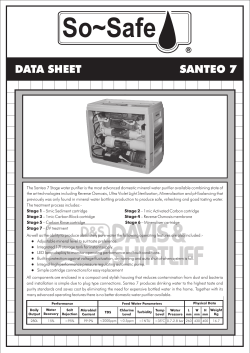


© Copyright 2026