
Traverse System Documentation Product Overview Guide Turin Networks Inc.
Turin Networks Inc.
Traverse System
Documentation
Product Overview Guide
Release TR3.0.x
Publication Date: January 2008
Document Number: 800-0001-TR30 Rev. A
FCC Compliance
This equipment has been tested and found to comply with the limits for a Class A digital device, pursuant to
Part 15 of the FCC Rules. This equipment generates, uses, and can radiate radio frequency energy and, if not
installed and used in accordance with the installation instructions may cause harmful interference to radio
communications.
Canadian Compliance
This Class A digital apparatus meets all requirements of the Canadian Interference-Causing Equipment
Regulations. Cet appareil numérique de la classe A respects toutes les exigences du Règlement sur le
matériel brouilleur du Canada.
Japanese Compliance
This is a Class A product based on the standard of the Voluntary Control Council for Interference by
Information Technology Equipment (VCCI). If this equipment is used in a domestic environment, radio
disturbance may occur, in which case, the user may be required to take corrective actions.
International Declaration of Conformity
We, Turin Networks, Inc. declare under our sole responsibility that the Traverse platform (models: Traverse
2000, Traverse 1600, and Traverse 600) to which this declaration relates, is in conformity with the following
standards:
EMC Standards
EN55022
EN55024
CISPR-22
Safety Standards
EN60950
CSA 22.2 No. 60950, ASINZS 3260
IEC 60950 Third Edition. Compliant with all CB scheme member country deviations.
Following the provisions of the EMC Directive 89/336/EEC of the Council of the European Union.
Copyright © 2008 Turin Networks, Inc.
All rights reserved. This document contains proprietary and confidential information of Turin Networks,
Inc., and may not be used, reproduced, or distributed except as authorized by Turin Networks. No part of this
publication may be reproduced in any form or by any means or used to make any derivative work (such as
translation, transformation or adaptation) without written permission from Turin Networks, Inc.
Turin Networks reserves the right to revise this publication and to make changes in content from time to time
without obligation on the part of Turin Networks to provide notification of such revision or change. Turin
Networks may make improvements or changes in the product(s) described in this manual at any time.
Turin Networks Trademarks
Turin Networks, the Turin Networks logo, Traverse, TraverseEdge, TransAccess, TransNav, and Creating
The Broadband Edge are trademarks of Turin Networks, Inc. or its affiliates in the United States and other
countries. All other trademarks, service marks, product names, or brand names mentioned in this document
are the property of their respective owners.
Government Use
Use, duplication, or disclosure by the U.S. Government is subject to restrictions as set forth in FAR 12.212
(Commercial Computer Software-Restricted Rights) and DFAR 227.7202 (Rights in Technical Data and
Computer Software), as applicable.
T RAVERSE P RODUCT O VERVIEW G UIDE
Contents
Section 1 Overview and Applications
About this Document . . . . . . . . . . . . . . . . . . . . . . . . . . . . . . . . . . . . . . . . . . .
Chapter 1
Introduction to the Traverse® Platform . . . . . . . . . . . . . . . . . . . . . . . . . . . . .
Chapter 2
Multiservice SONET/SDH Transport . . . . . . . . . . . . . . . . . . . . . . . . . . . . . . .
Chapter 3
IP Video Transport . . . . . . . . . . . . . . . . . . . . . . . . . . . . . . . . . . . . . . . . . . . .
Chapter 4
Carrier Ethernet. . . . . . . . . . . . . . . . . . . . . . . . . . . . . . . . . . . . . . . . . . . . . . .
Chapter 5
Wireless Backhaul and Bandwidth Management . . . . . . . . . . . . . . . . . . . . .
Chapter 6
International Transport Gateway . . . . . . . . . . . . . . . . . . . . . . . . . . . . . . . . . .
Chapter 7
New Generation Wideband DCS. . . . . . . . . . . . . . . . . . . . . . . . . . . . . . . . . .
Section 2 Platform Descriptions
Chapter 1
Traverse 2000 Platform. . . . . . . . . . . . . . . . . . . . . . . . . . . . . . . . . . . . . . . . .
Chapter 2
Traverse 1600 Platform. . . . . . . . . . . . . . . . . . . . . . . . . . . . . . . . . . . . . . . . .
Chapter 3
Traverse 600 Platform. . . . . . . . . . . . . . . . . . . . . . . . . . . . . . . . . . . . . . . . . .
Chapter 4
Fan Assemblies. . . . . . . . . . . . . . . . . . . . . . . . . . . . . . . . . . . . . . . . . . . . . . .
Chapter 5
Power Distribution and Alarm Panels . . . . . . . . . . . . . . . . . . . . . . . . . . . . . .
Section 3 Card (Module) Descriptions
Chapter 1
General Control Module (GCM) Cards . . . . . . . . . . . . . . . . . . . . . . . . . . . . .
Chapter 2
Next-Generation Ethernet Cards. . . . . . . . . . . . . . . . . . . . . . . . . . . . . . . . . .
Chapter 3
Gigabit Ethernet-only Cards (Dual-slot) . . . . . . . . . . . . . . . . . . . . . . . . . . . .
Chapter 4
SONET/SDH Cards. . . . . . . . . . . . . . . . . . . . . . . . . . . . . . . . . . . . . . . . . . . .
Chapter 5
Electrical Cards . . . . . . . . . . . . . . . . . . . . . . . . . . . . . . . . . . . . . . . . . . . . . . .
Chapter 6
Release TR3.0.x
Turin Networks
xvii
1-1
1-13
1-17
1-21
1-29
1-33
1-37
2-1
2-7
2-13
2-19
2-25
3-1
3-7
3-15
3-25
3-39
Page i
DRAFT
Traverse Product Overview Guide
VT/VC Switching Cards . . . . . . . . . . . . . . . . . . . . . . . . . . . . . . . . . . . . . . . . . 3-51
Section 4 Management System Overview
Chapter 1
TransNav Management System Overview . . . . . . . . . . . . . . . . . . . . . . . . . .
Chapter 2
Network Management Features . . . . . . . . . . . . . . . . . . . . . . . . . . . . . . . . . .
Chapter 3
User Interfaces . . . . . . . . . . . . . . . . . . . . . . . . . . . . . . . . . . . . . . . . . . . . . . .
Chapter 4
Management System Requirements . . . . . . . . . . . . . . . . . . . . . . . . . . . . . . .
Section 5 Planning and Engineering
Chapter 1
Traverse Specifications . . . . . . . . . . . . . . . . . . . . . . . . . . . . . . . . . . . . . . . . .
Chapter 2
Network Cabling using ECMs . . . . . . . . . . . . . . . . . . . . . . . . . . . . . . . . . . . .
Chapter 3
Network Cable Management . . . . . . . . . . . . . . . . . . . . . . . . . . . . . . . . . . . . .
Chapter 4
Protected Network Topologies. . . . . . . . . . . . . . . . . . . . . . . . . . . . . . . . . . . .
4-1
4-7
4-13
4-19
5-1
5-17
5-29
5-35
Section 6 Appendices
Appendix A
Compliance . . . . . . . . . . . . . . . . . . . . . . . . . . . . . . . . . . . . . . . . . . . . . . . . . . 6-1
Appendix B
Network Feature Compatibility. . . . . . . . . . . . . . . . . . . . . . . . . . . . . . . . . . . . 6-5
Appendix C
Acronyms and Abbreviations . . . . . . . . . . . . . . . . . . . . . . . . . . . . . . . . . . . . . 6-9
Index . . . . . . . . . . . . . . . . . . . . . . . . . . . . . . . . . . . . . . . . . . . . . . . . . . . . . . . . . Index-1
Page ii
DRAFT
Turin Networks
Release TR3.0.x
S ECTION 1
O VERVIEW
AND
A PPLICATIONS
S ECTION 1SYSTEM OVERVIEW
S ECTION 1SYSTEM OVERVIEW
Contents
Chapter 1
Introduction to the Traverse® Platform
Introduction . . . . . . . . . . . . . . . . . . . . . . . . . . . . . . . . . . . . . . . . . . . . . . . . . . . 1-1
Turin Solution . . . . . . . . . . . . . . . . . . . . . . . . . . . . . . . . . . . . . . . . . . . . . . . . . 1-1
Traverse Product Family . . . . . . . . . . . . . . . . . . . . . . . . . . . . . . . . . . . . . . . . . 1-2
Traverse 2000 . . . . . . . . . . . . . . . . . . . . . . . . . . . . . . . . . . . . . . . . . . . . . . . . . 1-3
Traverse 1600 . . . . . . . . . . . . . . . . . . . . . . . . . . . . . . . . . . . . . . . . . . . . . . . . . 1-4
Traverse 600 . . . . . . . . . . . . . . . . . . . . . . . . . . . . . . . . . . . . . . . . . . . . . . . . . . 1-5
Remote Applications . . . . . . . . . . . . . . . . . . . . . . . . . . . . . . . . . . . . . . . . 1-5
Traverse Applications . . . . . . . . . . . . . . . . . . . . . . . . . . . . . . . . . . . . . . . . . . . 1-5
Distributed Switching Architecture. . . . . . . . . . . . . . . . . . . . . . . . . . . . . . . . . . 1-6
Secondary Server Support . . . . . . . . . . . . . . . . . . . . . . . . . . . . . . . . . . . . . . . 1-6
Carrier-Class Redundancy . . . . . . . . . . . . . . . . . . . . . . . . . . . . . . . . . . . . . . . 1-7
Intelligent Control Plane . . . . . . . . . . . . . . . . . . . . . . . . . . . . . . . . . . . . . . . . . 1-7
Resource Discovery . . . . . . . . . . . . . . . . . . . . . . . . . . . . . . . . . . . . . . . . 1-8
Path Calculation . . . . . . . . . . . . . . . . . . . . . . . . . . . . . . . . . . . . . . . . . . . 1-8
Service Signaling. . . . . . . . . . . . . . . . . . . . . . . . . . . . . . . . . . . . . . . . . . . 1-8
Traverse Operating System Software . . . . . . . . . . . . . . . . . . . . . . . . . . . . . . . 1-9
Distributed Architecture . . . . . . . . . . . . . . . . . . . . . . . . . . . . . . . . . . . . . . 1-9
Software Upgrades . . . . . . . . . . . . . . . . . . . . . . . . . . . . . . . . . . . . . . . . . 1-10
General Control Redundancy . . . . . . . . . . . . . . . . . . . . . . . . . . . . . . . . . 1-10
Hitless Control Card Reboot . . . . . . . . . . . . . . . . . . . . . . . . . . . . . . . . . . 1-10
Hitless Warm Reboot. . . . . . . . . . . . . . . . . . . . . . . . . . . . . . . . . . . . . . . . 1-10
Dependability. . . . . . . . . . . . . . . . . . . . . . . . . . . . . . . . . . . . . . . . . . . . . . 1-11
Complimentary TransAccess Product Family . . . . . . . . . . . . . . . . . . . . . . . . . 1-11
TransAccess 200 Mux. . . . . . . . . . . . . . . . . . . . . . . . . . . . . . . . . . . . . . . . . . . 1-11
TransAccess 200 Mux Advantages: . . . . . . . . . . . . . . . . . . . . . . . . . . . . 1-11
TransAccess 155 Mux. . . . . . . . . . . . . . . . . . . . . . . . . . . . . . . . . . . . . . . . . . . 1-12
TransAccess 155 Mux Advantages: . . . . . . . . . . . . . . . . . . . . . . . . . . . . 1-12
Chapter 2
Multiservice SONET/SDH Transport
Introduction . . . . . . . . . . . . . . . . . . . . . . . . . . . . . . . . . . . . . . . . . . . . . . . . . . . 1-13
Multiservice Transport Application . . . . . . . . . . . . . . . . . . . . . . . . . . . . . . . . . 1-14
Integrated DWDM . . . . . . . . . . . . . . . . . . . . . . . . . . . . . . . . . . . . . . . . . . . . . . 1-15
Traverse Advantages . . . . . . . . . . . . . . . . . . . . . . . . . . . . . . . . . . . . . . . . . . . 1-15
Chapter 3
IP Video Transport
Release TR3.0.x
Turin Networks
Page xiii
Traverse Product Overview Guide,
Section 1 Overview and Applications
Introduction . . . . . . . . . . . . . . . . . . . . . . . . . . . . . . . . . . . . . . . . . . . . . . . . . . . 1-17
Turin’s IP Video Transport . . . . . . . . . . . . . . . . . . . . . . . . . . . . . . . . . . . . . . . . 1-18
IP Video Aggregation and Transport . . . . . . . . . . . . . . . . . . . . . . . . . . . . . . . . 1-19
Key Traverse IP Video Features . . . . . . . . . . . . . . . . . . . . . . . . . . . . . . . . . . . 1-19
Traverse Advantages. . . . . . . . . . . . . . . . . . . . . . . . . . . . . . . . . . . . . . . . . . . . 1-19
Chapter 4
Carrier Ethernet
Introduction . . . . . . . . . . . . . . . . . . . . . . . . . . . . . . . . . . . . . . . . . . . . . . . . . . . 1-21
Carrier Ethernet . . . . . . . . . . . . . . . . . . . . . . . . . . . . . . . . . . . . . . . . . . . . . . . . 1-22
Carrier Ethernet Aggregation and Transport . . . . . . . . . . . . . . . . . . . . . . . . . . 1-23
Key Traverse Ethernet Features . . . . . . . . . . . . . . . . . . . . . . . . . . . . . . . . . . . 1-23
Virtual Concatenation . . . . . . . . . . . . . . . . . . . . . . . . . . . . . . . . . . . . . . . . . . . 1-24
Link Capacity Adjustment Scheme . . . . . . . . . . . . . . . . . . . . . . . . . . . . . . . . . 1-24
Generic Framing Procedure . . . . . . . . . . . . . . . . . . . . . . . . . . . . . . . . . . . . . . 1-25
Rapid Spanning Tree Protocol. . . . . . . . . . . . . . . . . . . . . . . . . . . . . . . . . . . . . 1-25
Virtual Rapid Spanning Tree Protocol . . . . . . . . . . . . . . . . . . . . . . . . . . . . . . . 1-26
Link Aggregation . . . . . . . . . . . . . . . . . . . . . . . . . . . . . . . . . . . . . . . . . . . . . . . 1-26
Traffic Management. . . . . . . . . . . . . . . . . . . . . . . . . . . . . . . . . . . . . . . . . . . . . 1-26
Rate Limiting . . . . . . . . . . . . . . . . . . . . . . . . . . . . . . . . . . . . . . . . . . . . . . 1-26
Shaping . . . . . . . . . . . . . . . . . . . . . . . . . . . . . . . . . . . . . . . . . . . . . . . . . . 1-26
Congestion. . . . . . . . . . . . . . . . . . . . . . . . . . . . . . . . . . . . . . . . . . . . . . . . 1-26
Traverse Advantages. . . . . . . . . . . . . . . . . . . . . . . . . . . . . . . . . . . . . . . . . . . . 1-26
Chapter 5
Wireless Backhaul and Bandwidth Management
Introduction . . . . . . . . . . . . . . . . . . . . . . . . . . . . . . . . . . . . . . . . . . . . . . . . . . . 1-29
Economical Multiservice Transport . . . . . . . . . . . . . . . . . . . . . . . . . . . . . . . . . 1-30
Optimizing Wireless Networks . . . . . . . . . . . . . . . . . . . . . . . . . . . . . . . . . . . . . 1-31
Key Traverse Wireless Backhaul Features . . . . . . . . . . . . . . . . . . . . . . . . . . . 1-32
Traverse Advantages. . . . . . . . . . . . . . . . . . . . . . . . . . . . . . . . . . . . . . . . . . . . 1-32
Chapter 6
International Transport Gateway
Introduction . . . . . . . . . . . . . . . . . . . . . . . . . . . . . . . . . . . . . . . . . . . . . . . . . . . 1-33
A Global Solution . . . . . . . . . . . . . . . . . . . . . . . . . . . . . . . . . . . . . . . . . . . . . . . 1-33
SONET and SDH Provisioning . . . . . . . . . . . . . . . . . . . . . . . . . . . . . . . . . . . . 1-33
Broadband and Wideband Conversion and Switching . . . . . . . . . . . . . . . . . . 1-34
International Transport Gateway Advantages . . . . . . . . . . . . . . . . . . . . . . . . . 1-34
International Transport Gateway Diagram. . . . . . . . . . . . . . . . . . . . . . . . . . . . 1-35
. . . . . . . . . . . . . . . . . . . . . . . . . . . . . . . . . . . . . . . . . . . . . . . . . . . . . . . . . . . . . 1-35
Chapter 7
New Generation Wideband DCS
Introduction . . . . . . . . . . . . . . . . . . . . . . . . . . . . . . . . . . . . . . . . . . . . . . . . . . . 1-37
New Generation Wideband DCS . . . . . . . . . . . . . . . . . . . . . . . . . . . . . . . . . . . 1-38
Key Traverse WDCS Features . . . . . . . . . . . . . . . . . . . . . . . . . . . . . . . . . . . . 1-39
Traverse Advantages. . . . . . . . . . . . . . . . . . . . . . . . . . . . . . . . . . . . . . . . . . . . 1-39
Page xiv
Turin Networks
Release TR3.0.x
Traverse Product Overview Guide, Section 1 Overview and Applications
List of Figures
Figure 1-1
Figure 1-2
Figure 1-3
Figure 1-4
Figure 1-5
Figure 1-6
Figure 1-7
Figure 1-8
Figure 1-9
Figure 1-10
Figure 1-11
Figure 1-12
Release TR3.0.x
Traverse 2000 Shelf . . . . . . . . . . . . . . . . . . . . . . . . . . . . . . . . . . . 1-3
Traverse 1600 Shelf . . . . . . . . . . . . . . . . . . . . . . . . . . . . . . . . . . . 1-4
Traverse 600 Shelf . . . . . . . . . . . . . . . . . . . . . . . . . . . . . . . . . . . . 1-5
TransAccess 200 Mux. . . . . . . . . . . . . . . . . . . . . . . . . . . . . . . . . . 1-11
TransAccess 155 Mux. . . . . . . . . . . . . . . . . . . . . . . . . . . . . . . . . . 1-12
Multiservice SONET/SDH Transport Application . . . . . . . . . . . . . 1-14
IP Video Application . . . . . . . . . . . . . . . . . . . . . . . . . . . . . . . . . . . 1-18
Carrier Ethernet Application . . . . . . . . . . . . . . . . . . . . . . . . . . . . . 1-22
Bandwidth Efficiency with Virtual Concatenation . . . . . . . . . . . . . 1-24
Wireless Backhaul Application . . . . . . . . . . . . . . . . . . . . . . . . . . . 1-31
International Transport Gateway . . . . . . . . . . . . . . . . . . . . . . . . . 1-35
New Generation Wideband DCS Application . . . . . . . . . . . . . . . . 1-38
Turin Networks
Page xv
Traverse Product Overview Guide,
Page xvi
Section 1 Overview and Applications
Turin Networks
Release TR3.0.x
Product Overview [TR3.0.x]
Document Description
About this Document
Introduction
This description contains the following documentation topics:
• Traverse System Product Documentation, page xvii
• TraverseEdge System Product Documentation, page xviii
• TransNav Management System Product Documentation, page xix
• Operations Documentation, page xx
• Information Mapping, page xx
• If You Need Help, page xx
• Calling for Repairs, page xx
Refer to “” to review the new and changed features for this release.
Traverse
System
Product
Documentation
The Traverse® system product documentation set includes the documents described in
the table below.
Table 1 Traverse System Product Documentation
Document
Release TR3.0.x
Description
Target Audience
Traverse Product
Overview
This document provides a detailed overview of the
Traverse system. It also includes engineering and
planning information.
Anyone who wants to
understand the Traverse
system and its
applications.
Traverse
Installation and
Configuration
This document provides required equipment, tools,
and step-by-step procedures for:
• Hardware installation
• Power cabling
• Network cabling
• Node power up
• Node start-up
Installers, field, and
network engineers
Traverse
Provisioning
This document provides step-by-step procedures for
provisioning a network of Traverse nodes using the
TransNav management system. See the TransNav
Management System Product Documentation.
Network engineers,
provisioning, and
network operations
center (NOC)
personnel
Turin Networks
Page xvii
TraverseEdge System Product Documentation
TraverseEdge
System
Product
Documentation
The TraverseEdge™ 100 User Guide includes the sections described in the table below.
Table 2 TraverseEdge 100 System Product Documentation
Section
Page xviii
Description
Target Audience
Product Overview
This section provides a detailed overview of the
TraverseEdge system.
Anyone who wants to
understand the
TraverseEdge system
and its applications
Description and
Specifications
This section includes engineering and planning
information.
Field and network
engineers
Installation and
Configuration
This document identifies required equipment and
tools and provides step-by-step procedures for:
• Hardware installation
• Power cabling
• Network cabling
• Node power up
• Node start-up
Installers, field, and
network engineers
Provisioning the
Network
This section provides step-by-step procedures for
provisioning a TraverseEdge network using the
TransNav management system. Also see the
TransNav Management System Product
Documentation.
Network engineers,
provisioning, and
network operations
center (NOC)
personnel
Configuring
Equipment
This section provides step-by-step procedures for
configuring module and interface parameters of a
TraverseEdge using the TransNav management
system. Also see the TransNav Management
System Product Documentation.
Network engineers,
provisioning, and
network operations
center (NOC)
personnel
Creating TDM
Services
This section provides step-by-step procedures for
provisioning a TraverseEdge network using the
TransNav management system. Also see the
TransNav Management System Product
Documentation.
Network engineers,
provisioning, and
network operations
center (NOC)
personnel
Creating Ethernet
Services
This section provides step-by-step procedures for
provisioning a TraverseEdge network using the
TransNav management system. See the TransNav
Management System Product Documentation.
Network engineers,
provisioning, and
network operations
center (NOC)
personnel
Appendices
This section provides installation and provisioning
checklists, compliance information, and acronym
descriptions.
Installers and anyone
who wants reference
information.
Turin Networks
Release TR3.0.x
TransNav Management System Product Documentation
TransNav
Management
System
Product
Documentation
The TransNav™ management system product documentation set includes the
documents described in the table below.
Table 3 TransNav Management System Product Documentation
Document
Description
TransNav
Management
System Product
Overview
This document provides a detailed overview of the
TransNav management system.
TransNav
Management
System Server
Guide
This document describes the management server
component of the management system and provides
procedures and troubleshooting information for the
server.
TransNav
Management
System GUI
Guide
This document describes the graphical user interface
including installation instructions and logon
procedures.
This document includes hardware and software
requirements for the management system. It also
includes network management planning information.
Target Audience
Anyone who wants to
understand the
TransNav management
system
Field and network
engineers,
provisioning, and
network operations
center (NOC)
personnel
This document describes every menu, window, and
screen a user sees in the graphical user interface.
Release TR3.0.x
TransNav
Management
System CLI
Guide
This document includes a quick reference to the
command line interface (CLI). Also included are
comprehensive lists of both the node-level and
domain-level CLI commands.
TransNav
Management
System TL1
Guide
This document describes the syntax of the TL1
language in the TransNav environment.
This document also defines all input commands and
expected responses for retrieval commands as well as
autonomous messages that the system outputs due to
internal system events.
Turin Networks
Page xix
Operations Documentation
Operations
Documentation
The document below provides operations and maintenance information for Turin’s
TransNav managed products.
Table 4 Operations Documentation
Document
Node Operations
and Maintenance
Information
Mapping
Description
This document identifies required equipment and
tools. It also provides step-by-step procedures for:
• Alarms and recommended actions
• Performance monitoring
• Equipment LED and status
• Diagnostics
• Test access (SONET network only)
• Routine maintenance
• Node software upgrades
• Node hardware upgrades
Target Audience
Field and network
engineers
Traverse, TransNav, and TraverseEdge 100 system documentation uses the Information
Mapping format which presents information in small units or blocks. The beginning of
an information block is identified by a subject label in the left margin; the end is
identified by a horizontal line. Subject labels allow the reader to scan the document and
find a specific subject. Its objective is to make information easy for the reader to
access, use, and remember.
Each procedure lists the equipment and tools and provides step-by-step instructions
required to perform each task. Graphics are integrated into the procedures whenever
possible.
If You Need
Help
If you need assistance while working with Traverse products, contact the Turin
Networks Technical Assistance Center (TAC):
• Inside the U.S., toll-free: 1-866-TURINET (1-866-887-4638)
• Outside the U.S.: 916-348-2105
• Online: www.turinnetworks.com/html/support_overview.htm
TAC is available 6:00AM to 6:00PM Pacific Time, Monday through Friday (business
hours). When the TAC is closed, emergency service only is available on a callback
basis. E-mail support (24-hour response) is also available through:
[email protected].
Calling for
Repairs
If repair is necessary, call the Turin Repair Facility at 1-866-TURINET (866-887-4638)
for a Return Material Authorization (RMA) number before sending the unit. The RMA
number must be prominently displayed on all equipment cartons. The Repair Facility is
open from 6:00AM to 6:00PM Pacific Time, Monday through Friday.
When calling from outside the United States, use the appropriate international access
code, and then call 916-348-2105 to contact the Repair Facility.
Page xx
Turin Networks
Release TR3.0.x
Calling for Repairs
When shipping equipment for repair, follow these steps:
1. Pack the unit securely.
2. Enclose a note describing the exact problem.
3. Enclose a copy of the invoice that verifies the warranty status.
4. Ship the unit PREPAID to the following address:
Turin Networks, Inc.
Turin Repair Facility
Attn: RMA # ________
1415 North McDowell Blvd.
Petaluma, CA 94954 USA
Release TR3.0.x
Turin Networks
Page xxi
Calling for Repairs
Page xxii
Turin Networks
Release TR3.0.x
S ECTION 1OVERVIEW AND APPLICATIONS
Chapter 1
Introduction to the Traverse ® Platform
Introduction
Service providers worldwide are faced with the challenge of modernizing their
transport networks to accommodate new high-bandwidth IP services, such as
broadband Internet access and video-on-demand, in addition to today’s
revenue-generating voice and leased-line services. Turin’s multiservice optical
transport platform is a next-generation solution designed specifically to meet this
challenge. Deployed in carriers’ access, metro, and interoffice (IOF) networks, the
Traverse platform transports and manages any combination of traditional electrical
TDM and optical SONET/SDH services, as well as next-generation switched Ethernet
services more efficiently and cost-effectively than legacy solutions.
This chapter includes the following topics:
• Turin Solution, page 1-1
• Traverse Product Family, page 1-2
• Traverse Applications, page 1-5
• Distributed Switching Architecture, page 1-6
• Secondary Server Support, page 1-6
• Carrier-Class Redundancy, page 1-7
• Intelligent Control Plane, page 1-7
• Traverse Operating System Software, page 1-9
• Complimentary TransAccess Product Family, page 1-11
Turin Solution
The Turin® Traverse platform simplifies carriers’ transport networks and lowers their
costs by integrating the functions of a SONET/SDH add-drop multiplexer (ADM), a
digital cross-connect system (DCS), and an Ethernet switch in a single compact shelf.
The Traverse platform’s design also supports a wide variety of electrical and optical
service interfaces, including DS1, E1, DS3/EC-1 (Clear Channel and Transmux), E3,
OC-3/STM-1, OC-12/STM-4, OC-48/STM-16, OC-192/STM-64, as well as switched
Fast Ethernet and Gigabit Ethernet. This flexibility lowers carriers capital and
operational expenditures by reducing the need to purchase and manage multiple
separate ADM, DCS, and Ethernet switching systems, as well as the rack space and
power they would require.
The Traverse platform supports standard SONET/SDH features such as comprehensive
performance monitoring, VT/TU capacity monitoring, the ability to aggregate and
groom TDM traffic at both wideband (STS/VC) and broadband (STS/STM)
Release TR3.0.x
Turin Networks
Page 1-1
Traverse Product Overview Guide, Section 1: Overview and Applications
Traverse Product Family
granularities, and applications such as 1+1 point-to-point, linear ADM, optical hub, and
protected rings.
In addition to these standard capabilities, the Traverse platform incorporates powerful
Ethernet traffic management and Layer 2 Ethernet switching with advanced standards
such as GFP, VCAT, LCAS, RSTP, and Link Aggregation to ensure optimized transport
of IP/Ethernet traffic over SONET/SDH networks. This SONET/SDH-based,
packet-optimized architecture enables the Traverse platform to integrate seamlessly
with carriers’ existing networks and protect today’s investments, while laying the
groundwork for future expansions into new technologies.
The Traverse platform supports a variety of carrier-class applications. The system is
developed to enable solutions that service providers can implement in today’s highly
competitive communications markets.
Traverse
Product Family
Page 1-2
The Turin Networks Traverse product family is comprised of three scalable platforms
optimized for deployments ranging from outside plant (OSP) cabinets and multi-tenant
units (MTU) to metro and IOF environments. All three Traverse shelves, including the
20-slot Traverse 2000, the 16-slot Traverse 1600, and the 6-slot Traverse 600, are built
upon the same architecture and use the same interface and control cards.
• Traverse 2000, page 1-3
• Traverse 1600, page 1-4
• Traverse 600, page 1-5
Turin Networks
Release TR3.0.x
Chapter 1 Introduction to the Traverse® Platform
Traverse 2000
Traverse 2000
The Traverse 2000 platform is a multiservice transport system designed to simplify
service provider’s networks and enable the delivery of SONET-based, SDH-based, and
next-generation data services. The Traverse 2000 platform is:
• A 20-slot, 23-inch wide rack-mountable shelf (four slots per 7-foot rack)
• Optimized for stacked ring, metro/IOF hub switching, and transport applications
• Scalable to 95 Gbps of STS/STM switching capacity with the industry’s highest
DS1/E1 to OC-192/STM-64, 10/100, and Gigabit Ethernet service densities
• High-capacity wideband digital cross-connect matrix scales from 96 to 384
protected STS/STM equivalents (2688 to 10,752 VT1.5s)
Figure 1-1 Traverse 2000 Shelf
See Section 2—Platform Descriptions, Chapter 1—“Traverse 2000 Platform,”
page 2-1 for the complete description and specifications for this platform.
Release TR3.0.x
Turin Networks
Page 1-3
Traverse Product Overview Guide, Section 1: Overview and Applications
Traverse 1600
Traverse 1600
The Traverse 1600 platform unifies the functions of a next-generation ADM and DCS
with an edge Ethernet aggregation switching in a single carrier-class shelf. The
Traverse 1600 is:
• A 16-slot, 19-inch wide rack-mountable shelf (four slots per 7-foot rack)
• Optimized for access and metro/IOF ring switching, as well as transport
applications
• Scalable to 75 Gbps STS/STM switching capacity with high-density DS1/E1 to
OC-192/STM-64, 10/100 and Gigabit Ethernet service flexibility
Figure 1-2 Traverse 1600 Shelf
See Section 2—Platform Descriptions, Chapter 2—“Traverse 1600 Platform,”
page 2-7 for the complete description and specifications for this platform.
Page 1-4
Turin Networks
Release TR3.0.x
Chapter 1 Introduction to the Traverse® Platform
Traverse Applications
Traverse 600
The Traverse 600 platform is the most a space-efficient member of the Traverse
product family. The Traverse 600 is:
• A compact, 6-slot, 3.72 rack-unit high shelf
• Rack-mountable for deployment in access rings, MTUs, and OSP cabinets
• A flexible solution offering medium density DS1/E1 to OC-48/STM-16, 10/100,
and Gigabit Ethernet services
Figure 1-3 Traverse 600 Shelf
See Section 2—Platform Descriptions, Chapter 3—“Traverse 600 Platform,”
page 2-13 for the complete description and specifications for this platform.
Remote Applications
A Traverse 600 shelf can be located in remote locations such as building equipment
rooms, Controlled Environmental Vaults (CEVs), walk-in cabinets, remote central
offices (CO), and multiple-dwelling unit (MDU) environments. It can be installed in
standard 23-inch (584 mm) wide central office racks, standard 19-inch (483 mm) wide
computer racks, and can also be wall mounted.
The Traverse 600 system is powered by a -48 VDC power source (-40 to -60 VDC
operating range) in central office, remote cabinet, or CEV installations. It has front
access for easy installation, cable management, card insertion and removal.
Traverse
Applications
Release TR3.0.x
The Traverse platform supports a variety of carrier-class features. The system is
developed to enable solutions that service providers can implement in today’s highly
competitive communications markets.
• Chapter 2—“Multiservice SONET/SDH Transport,” page 1-13
• Chapter 3—“IP Video Transport,” page 1-17
• Chapter 4—“Carrier Ethernet,” page 1-21
• Chapter 5—“Wireless Backhaul and Bandwidth Management,” page 1-29
• Chapter 6—“International Transport Gateway,” page 1-33
• Chapter 7—“New Generation Wideband DCS,” page 1-37
Turin Networks
Page 1-5
Traverse Product Overview Guide, Section 1: Overview and Applications
Distributed Switching Architecture
Distributed
Switching
Architecture
The Traverse platform implements a patent-pending distributed switching architecture
that delivers flexibility and true “pay as you grow” system scalability. Within this
framework, each individual Traverse card incorporates a powerful switching ASIC
(application specific integrated circuit) that participates as a member of the distributed
switch fabric across the Traverse platform’s fully-interconnected passive mesh
backplane. This distributed switching technique allows non-blocking increases in
system capacity from 2.5 Gbps up to 95 Gbps per Traverse 2000 shelf. In addition, the
flexible nature of this architecture is designed to handle any combination of TDM, cell
and packet transmissions with equal facility, and supports any service interface card
type (e.g., optical or electrical, trunk or tributary, packet-based, or TDM-based) in any
system slot.
The Traverse distributed switching ASIC performs both time slot assignment (TSA)
and time slot interchange (TSI) functionality at the STS/STM level on all cards. That is,
each Traverse line card can pass through, add, drop, or drop-and-continue (broadcast)
traffic, including hairpinned connections.
The distributed switching architecture lowers startup costs for the Traverse platform
because no centralized switch-fabric is required for the system. In addition, it allows
carriers to increase the capacity of their Traverse shelf in an incremental “pay as you
grow” manner by adding service cards. Customers pay only for the services and
capacity they require.
Secondary
Server Support
The TransNav management system supports one Primary server and up to seven
Secondary servers in the network. The Primary server actively manages the network,
while the secondary servers passively view the network but do not perform any
management operations that would change the network. If the Primary server fails or is
scheduled for maintenance, any Secondary server can be manually changed to take the
Primary server role.
Critical information on the Secondary servers is synchronized with the network
elements automatically in real time. This includes current provisioning, service state,
alarm and event information from the Traverse nodes. To synchronize PM data,
Domain user login profile, user preferences and roles, customer records, alarm
acknowledgements and annotations, reports and report templates and schedules, the
Primary server database must be manually exported and then imported to the
Secondary server database.
Manual synchronization should be performed on a Secondary server database before it
is promoted to a Primary server role. For detailed information on promoting a
Secondary server, see the TransNav Management System Server Guide,
Chapter 3—“Server Administration Procedures.”
Page 1-6
Turin Networks
Release TR3.0.x
Chapter 1 Introduction to the Traverse® Platform
Intelligent Control Plane
Carrier-Class
Redundancy
The Traverse platform is engineered to meet the 99.999% availability levels required
for carrier-grade deployments. Redundancy and fault-tolerance are built into all system
functions to provide a robust and reliable service delivery platform. As a fully ANSI
and ETSI capable system, the Traverse platform is both NEBS Level 3 and CE Mark
compliant.
The Traverse platform supports a variety of facility and equipment protection schemes:
• All optical service interface modules (SIMs or cards) support 1+1 APS, 1+1 Path,
UPSR and SNCP.
• The OC-48/STM-16 and OC-192/STM-64 cards also support 2-fiber BLSRs and
MS-SPRings.
• All electrical cards, including the DS1, E1, DS3/EC-1, and E3 support optional 1:N
(where N=1, 2) equipment protection.
• The VT/VC switching and DS3 transmultiplexing cards support 1:N equipment
protection.
• The next-generation Ethernet cards support 1:1 equipment protection on the
electrical interfaces: GbE TX and 10/100BaseTX.
• The Traverse General Control Module cards (control cards) and Turin’s
next-generation Ethernet cards support 1:1 equipment protection.
All system components, including SIMs (cards), control cards, and the electrical
connector modules (ECMs), are hot-swappable and easily accessible. Additionally,
both hardware and software upgrades can be performed “in-service” on the Traverse
platform, without interruption to existing network traffic. This capability allows the
transport network to expand gracefully as new customers and service requirements are
added.
Intelligent
Control Plane
The Intelligent Control Plane optimizes bandwidth utilization, enables traffic
engineering, and provides system management. It is extensible to support multiple
technologies including wavelength, SONET/SDH, virtual tributaries, Ethernet, ATM,
MPLS, IP, and all related networking services.
The Intelligent Control Plane is a logical set of connections among Traverse nodes that
allows the nodes to exchange control and management information. The set of Traverse
nodes that are completely interconnected by the Intelligent Control Plane is called a
domain. It performs the following functions across the Traverse services network:
• Resource Discovery: Learns the set of network elements, the available interfaces,
and the topology of links between those interfaces.
• Path Calculation: For a particular service, calculates a path across the network
that makes efficient use of the network elements and links.
• Service Signaling: Configures each network element in the path with all the
parameters needed to turn up the service.
• Policy Enforcement: Guides the automatic behavior of the control plane.
The Intelligent Control Plane implements Generalized MPLS signaling methods used
to establish transport connectivity in the Traverse Services Network. It automatically
discovers neighboring nodes and interconnected links, using an Open Shortest Path
First (OSPF) with Traffic Engineering (TE) extensions routing protocol.
Release TR3.0.x
Turin Networks
Page 1-7
Traverse Product Overview Guide, Section 1: Overview and Applications
Intelligent Control Plane
Resource Discovery
After each Traverse node initializes, it negotiates link properties with the network
element at the other end of each link. This includes properties such as data formats and
error monitoring. After successfully completing the negotiation, each Traverse node is
able to communicate fully with its neighbors.
Next, the topology discovery protocol starts up. This protocol is simple in concept.
First it learns what network elements are directly connected to its links. For instance,
Traverse node A learns that Traverse node B is its neighbor. Next, it exchanges all the
information it has learned with its neighbors, e.g., Traverse node A knows that Traverse
node C is two hops away. At the completion of these steps, every node has learned the
entire network topology. In practice, in a large network, several rounds of messages are
exchanged before each Traverse node understands the complete topology. This process
completes rapidly and automatically.
The topology discovery protocol (OSPF-TE) also distributes information about
resource usage at each Traverse node. This information populates the
traffic-engineering database that maintains a record of resource utilization and
performance at each node in the network. The discovery protocol runs continuously
and updates the traffic-engineering database in real time.
Using the link-state database and the traffic engineering database, the Intelligent
Control Plane can find the best path to set up a circuit across the Traverse Services
Network. At this point, without any human intervention, every Traverse node
participating in the Intelligent Control Plane has complete knowledge of the network.
The network is now ready to accept service requests.
Path Calculation
A service request is initiated by the Traverse management software sending a request to
a single Traverse node—typically one of the end points of the desired service. That
Traverse node searches its traffic engineering database to find the “best” path between
the service end points. “Best” is defined as the path that minimizes some measure, such
as number of links or network delay, while also satisfying the constraints and policies
specified by the user.
The constraints provide a way for path selection without requiring manual selection.
Typical constraints include:
• Avoid specific nodes and links. This is used most often to achieve
failure-independent paths. Nodes and links that share some risk (such as fibers in
the same conduit or central offices in the same earthquake zone) are collected into
groups. Paths can be requested that draw their resources from different groups.
• Include specific nodes. A special case is to fully specify every node in the path.
This can be used in cases where manual path calculation is desired.
• Meet certain delay or jitter properties.
• Utilize special topologies such as SONET/SDH rings.
Service Signaling
Once a path has been selected, RSVP-TE1 signaling protocols are used to set up each
Traverse node in the path. At each node, resource management is performed to ensure
Page 1-8
Turin Networks
Release TR3.0.x
Chapter 1 Introduction to the Traverse® Platform
Traverse Operating System Software
that setting up the service will allow the new service and all existing ones to meet their
quality of service obligations. The path calculation takes this into account, although the
traffic engineering database may be a few seconds behind the actual network
utilization. Each Traverse node along the path does a final check and reserves the
resources for the service. If any Traverse node cannot fulfill the service requirements,
an error is generated, and all the reserved resources at other Traverse nodes in the path
are released. At this point, path calculation is repeated with updated information.
Once service signaling is complete, the service can be made available to the end user.
The entire process takes a matter of seconds—real-time service creation that allows
service requests to begin generating revenue immediately.
The work of the Intelligent Control Plane does not stop once the service has been
created—it is continually updating its traffic engineering database to deal with failures
and changing network loads.
Traverse
Operating
System
Software
The versatility and value of the Traverse system is underpinned by the advanced
architecture and design of the Turin Networks Traverse operating system software. The
operating system and future extensions to it have one goal: enable service providers to
rapidly conceive new service offerings, as well as quickly engineer, deploy, sell, and
bill.
The Traverse operating system provides a distributed architecture with numerous
redundancy and dependability features. These enable a host of benefits to carriers,
among them:
• Automatic card discovery
• Network topology management
• Numerous plug-and-play features
• Scalable bandwidth (from 1.5 Mbps to 10 Gbps)
• Demand-based services (ADM, DCS, IP)
• Multiple network topologies (Linear, Ring, Mesh, Add-Drop)
• A unified Intelligent Control Plane
• Distributed networking
• Scalable bandwidth with fine-grain Quality of Service management
• Intelligent distributed management plane architecture
Distributed Architecture
Intelligent service provisioning and bandwidth brokering are made possible by the
Traverse operating system’s distributed architecture.2 This architecture enables a large
array of software features:
• Control card redundancy control
• IP-based control plane for neighbor discovery and connection set-up
Release TR3.0.x
1
Resource ReSerVation Protocol with Traffic Engineering extensions.
2
The Traverse OS resides on the control cards and the SIMs.
Turin Networks
Page 1-9
Traverse Product Overview Guide, Section 1: Overview and Applications
Traverse Operating System Software
•
•
•
•
•
•
•
•
Equipment provisioning and alarm and performance monitoring for all cards and
components
Facility provisioning, alarm, and performance monitoring for service and timing
interfaces
STS-level and STM-level cross-connect provisioning, alarm, and performance
monitoring
VT-level and VC11/VC12-level cross-connect provisioning, alarm, and
performance monitoring
VT/TU capacity monitoring for SONET and SDH
UPSR, BLSR, SNCP, and MS-SPRing operation
1:1 and/or 1:2 equipment protection for electrical and Ethernet cards
1+1 APS, 1+1 MSP, 1+1 Path, and SNCP protection for SONET/SDH interfaces
Software Upgrades
You can perform upgrades to the Traverse operating system on all component cards
with no impact or interference of Traverse operations and services. The upgrade feature
offers either the hitless warm reboot or a cold reboot option. Software upgrades or
reversions to all cards can be done locally or remotely. Traverse cards can store two
complete software images to support software upgrade and reversion. A new image on
any service card is backward compatible with the previous version on other service
cards. Therefore, the network operator can upgrade the image of one card at a time in a
Traverse shelf.
Service card configuration and provisioned services are saved in the persistent
databases on the control cards. When a new or replacement service card is inserted (or
a Traverse system restarts), the Intelligent Control Plane configures and provisions the
persistent data. Thus, the Traverse system, network, and services return to the prior
state.
General Control Redundancy
Engineered with multiple fault-tolerant and redundant components, the Traverse
operating system can operate from a single general control module (GCM) card or in a
system with mated control cards. In a redundant configuration, each control card has an
arbiter circuit to elect active and standby modes, and to support protection switching.
This functionality allows for hitless software upgrades and fault recoveries. The warm
reboot feature on control cards allows for a hitless reboot (switchover the
active/standby role) of control cards with integrated optic ports.
Hitless Control Card Reboot
All Traverse line cards, facilities (ports), and services (traffic) operate continuously
without interruption upon control card reboot in a single or redundant (dual) control
card configuration, excepting Legacy Ethernet cards. The control card performs
in-service auditing of the line cards, protection groups, services, and alarms.
Hitless Warm Reboot
The Traverse provides a hitless warm reboot function and user interface for all cards
(excepting Legacy Ethernet) in order to restart the processor. The warm reboot is hitless
Page 1-10
Turin Networks
Release TR3.0.x
Chapter 1 Introduction to the Traverse® Platform
TransAccess 200 Mux
to traffic (excepting SONET/SDH transparent and Ethernet RSTP services). The card
resumes its full functionality to respond to provisioning and protection switching
requests within 60 seconds of the warm reboot command.
Dependability
The Traverse operating system is built upon an industry-standard kernel, considerably
enhanced by a Turin Networks-developed software layer that provides carrier-class
reliability. This implementation includes:
• Dynamic service card loading and unloading
• Application supervision
• Network-wide inter-process communication, and other advanced features that
allow for automatic auditing of critical system resources, critical situation
detection, and automatic recovery without the necessity of service card reset
• Turin High Availability Framework, providing infrastructure for application-level
data replication over a unified interface
Complimentary
TransAccess
Product Family
Turin Networks offers a broadband multiplexer family of products to compliment the
Traverse platform:
• TransAccess 200 Mux, page 1-11
• TransAccess 155 Mux, page 1-12
TransAccess
200 Mux
The Turin Networks TransAccess 200 Mux takes multiplexing to a new level of
flexibility and space efficiency. Connect your T1s or E1s into a TransAccess 200 Mux
and transport them as traditional T1s in an OC-3 or as E1s in an STM-1. Choose a
number of multiplexing options, including T1 and T3 to OC-3, T1 to VT1.5 to STS-1 to
OC-3, E1 to T3 to OC-3, E1 to VT2 to STS-1 to OC-3, or E1 to TU-12 to AU3 to
STM-1. The low power consumption and small footprint (2 RU) make it ideal for
co-locations. A carrier-class solution, the TransAccess 200 Mux provides 1:1
redundancy on both the high-speed and drop ports for added reliability. Integrated
T1/E1 testing makes fault isolation routine, and, unlike most M13 muxes, T1/E1
framing information is included to provide additional performance statistics.
Figure 1-4 TransAccess 200 Mux
TransAccess 200 Mux Advantages:
•
•
•
•
•
•
•
Release TR3.0.x
Mux T1/E1 to STS-1/AU-3 or T3 on one card
Mux T3/STS-1/AU-3 to OC-3/STM-1 on one card
Compact and cost-effective
Easy installation, administration, and scaling
Service availability with 1:1 protection and hot-swappable cards
Advanced diagnostics
Integrated element management
Turin Networks
Page 1-11
Traverse Product Overview Guide, Section 1: Overview and Applications
TransAccess 155 Mux
•
•
23-inch or 19-inch rack mount options
NEBS level 3, UL/C-UL, FCC Part 15, and CE Mark certified
For further information, see the TransAccess 200 Mux Operations Manual.
TransAccess
155 Mux
The Turin Networks TransAccess 155 Mux combines the functionality of three
complete M13 multiplexers with an OC-3 Add-Drop Multiplexer. At only 1 rack
mounting unit in height, the Turin Networks TransAccess 155 Mux continues Turin’s
tradition of providing the densest broadband multiplexing solutions available.
The TransAccess 155 Mux is ideal for mass termination of OC-3 signals,
highly-efficient intra-office transport of T1/E1s, or anywhere space is at a premium or
low power consumption is a must. The TransAccess 155 Mux also supports UPSR ring
deployment. T1s and E1s can be mixed within an OC-3. Extensive diagnostic and
alarm features are standard. Redundancy is available for all circuitry. Internal, external,
through, line, and loop timing modes are available.
Figure 1-5 TransAccess 155 Mux
TransAccess 155 Mux Advantages:
•
•
•
•
•
•
•
•
Combines 3 T3 signals each containing 28 T1s or 21 E1s
Optical OC-3 interface at intermediate and long reach
Compact and cost-effective
Flexible configuration: Add-Drop Ring or Terminal mode
Easy installation, administration, and scaling
Service availability with 1:1 protection and hot-swappable cards
Advanced diagnostics
NEBS level 3, UL/C-UL, FCC Part 15 Class A certified
For further information, see the TransAccess 155 Mux Operations Manual.
Page 1-12
Turin Networks
Release TR3.0.x
S ECTION 1OVERVIEW AND APPLICATIONS
Chapter 2
Multiservice SONET/SDH Transport
Introduction
The Traverse platform combines SONET/SDH ADM and broadband digital
cross-connect system (DCS) functionality to create an advanced bandwidth
management system that supports true “any to any” cross-connection ability. This
bandwidth management flexibility enables the system to be deployed in any
combination of ring and linear topologies and provides any mix of tributary and trunk
connections (DS1/E1 to OC-192/STM-64). In addition to conserving bandwidth for
more efficient and cost-effective network management, this architecture effectively
removes the requirement for expensive external broadband DCS in applications such as
inter-connected rings.
SDH and SONET are high-speed optical communications protocols that represent the
foundation of today’s global optical transport network. As a principal application, the
Traverse platform provides multiservice SONET/SDH transport capabilities that serve
the dual roles of an add-drop multiplexer (ADM) and a DCS.
This chapter describes the following topics:
• Multiservice Transport Application, page 1-14
• Integrated DWDM, page 1-15
• Traverse Advantages, page 1-15
Release TR3.0.x
Turin Networks
Page 1-13
Traverse Product Overview Guide, Section 1: Overview and Applications
Multiservice Transport Application
Multiservice
Transport
Application
In multiservice SONET/SDH transport applications, the Traverse platform aggregates
any combination of lower rate signals, grooming and switching them into higher-rate
optical signals, or dropping them to be transported on different facilities.
Traverse 1600
Traverse 2000
Traverse 1600
Traverse 600
Traverse 600
TransNav
management
system
Figure 1-6 Multiservice SONET/SDH Transport Application
The Traverse platform is deployable throughout service providers’ transport networks,
such as those found in central offices, POPs, or remote terminals. In these carrier
facilities, the Traverse system transports any combination of wideband or broadband
services and circuit-based or packet-based voice, data, and video services and
interconnects SONET/SDH rings all from a common platform.
Ideal for service providers looking to expand the capacity of their transport networks
and evolve to support high-bandwidth IP services such as video, the Traverse platform
offers significant advantages over traditional SONET/SDH solutions. In addition to
supporting standard protected rings, hub, point-to-point, and linear add/drop
deployments, the system’s advanced bandwidth management capability supports both
uni- and bi-directional connections, drop-and-continue for dual-node ring
interconnection, broadcast, and protected mesh topologies.
Page 1-14
Turin Networks
Release TR3.0.x
Chapter 2 Multiservice SONET/SDH Transport
Traverse Advantages
Integrated
DWDM
Dense wavelength division multiplexing (DWDM) allows multiple streams of data,
each using a separate wavelength, to travel along the same fiber at the same time.
DWDM multiplies the capacity of a fiber by the number of wavelengths present,
allowing service providers to increase the available bandwidth in their networks
without incurring the expense of adding fiber. The Traverse platform offers integrated
DWDM capabilities, with OC-48/STM-16 and OC-192/STM-64 wavelengths based on
the ITU grid, at spacings of 100 GHz.
Traverse
Advantages
In addition to the key features, the Traverse platform offers the following advantages:
• The Traverse product family addresses a wide range of applications across service
providers’ access, metro, and IOF networks.
• Support for broad range of electrical and optical ANSI and ETSI interfaces: DS1,
DS3/EC-1, E1, E3, OC-3/STM-1, OC-12/STM-4, OC-48/STM-16,
OC-192/STM-64, 10/100 and GbE with industry leading port densities.
• Advanced bandwidth management capabilities enable any combination of linear,
ring, and inter-connected ring topologies.
• The high-capacity Traverse architecture scales to an add-drop capacity of 95 Gbps
(1824 x 1824 STS-1/STM cross-connect matrix).
• Automated end-to-end service provisioning using Turin’s TransNav management
system.
• Server redundancy with 1 Primary server supporting up to 7 Secondary servers.
Release TR3.0.x
Turin Networks
Page 1-15
Traverse Product Overview Guide, Section 1: Overview and Applications
Traverse Advantages
Page 1-16
Turin Networks
Release TR3.0.x
S ECTION 1OVERVIEW AND APPLICATIONS
Chapter 3
IP Video Transport
Introduction
ILECs, rural telephone companies in particular, are looking to complete the “triple
play” of voice, video, and data services by delivering IP-based Digital Television
services (IP-TV). In addition to providing traditional telephone companies an important
new source of revenues, IP-TV services also enable them to compete more effectively
with cable companies looking to enter the voice services business by deploying Voice
over IP (VoIP) technology.
IP Multicast has emerged as a critical enabling technology for IP-TV. In this
architecture, IP-Video Headend equipment distributes individual channels to viewers as
IP Multicast Groups (IPMGs). Newer generation access platforms, such as IP-based
DSLAMs, Broadband Loop Carriers (BLCs), and OLTs, incorporate a technique known
as “IPMG snooping,” which enables viewers to change channels by dynamically
adding and/or dropping them from specific multicast groups. As IP-based platforms,
the standard interface for Headend equipment and newer generation access platforms is
Gigabit Ethernet (GbE).
While nearly all of the focus on delivering the triple play revolves around the access
network, IP-TV and IP-Video also have a significant impact on the critical technologies
and systems between a services provider’s last mile infrastructure and the
headend—namely the inter-office (IOF) transport network. In addition to creating very
real potential of overwhelming deployed network capacity, IP-Video presents service
providers with other significant challenges, such as choosing how to best integrate
Ethernet within their network, selecting the optimal protection methods to employ, and
determining how to ensure QoS for a likely mix of broadcast, multicast, and unicast
programming.
This chapter describes the following topics:
• Turin’s IP Video Transport, page 1-18
• IP Video Aggregation and Transport, page 1-19
• Key Traverse IP Video Features, page 1-19
• Traverse Advantages, page 1-19
Release TR3.0.x
Turin Networks
Page 1-17
Traverse Product Overview Guide, Section 1: Overview and Applications
Turin’s IP Video Transport
Turin’s IP
Video
Transport
Turin Networks leads the industry in enabling service providers to expand and evolve
their transport infrastructure to support IP-TV and IP-Video. Turin’s flagship Traverse
platform combines powerful Ethernet switching with scalable, ultra-reliable
SONET/SDH transport in a single carrier-class chassis. The Traverse platform
integrates intelligent Layer 2 Ethernet switching with advanced VLAN and traffic
management to support a mix of broadcast, multicast, and unicast IP-Video. The
Traverse shelf provides high GbE port density to aggregate new generation access
platforms such as IP-DSLAMs, as well as to interface with the IP-Video Headend.
Transporting GbE-based IP-Video over SONET/SDH enables an incremental and
cost-effective migration to a packet-optimized transport infrastructure. Along with
ensuring guaranteed bandwidth with ultra-low latency and jitter—an essential
requirement for video—this architecture realizes greater than 95% network utilization
using GFP, VCAT, and LCAS. The Traverse platform scales to 100 Gbps in switching
capacity and supports multiple OC-192/STM-64 rings. The truly carrier-class
resiliency capabilities of SONET/SDH are delivered, as well as industry-first Ethernet
equipment and facility protection, without relying on proprietary, pre-standard
technologies.
TransNavTM
Traverse 1600
Traverse
2000
Traverse 1600
Figure 1-7 IP Video Application
Page 1-18
Turin Networks
Release TR3.0.x
Chapter 3 IP Video Transport
Traverse Advantages
IP Video
Aggregation
and Transport
The Traverse platform is ideally suited for transporting IP-Video traffic, as well as for
aggregating both traditional DSLAM/DLC platforms and new generation
IP-DSLAMs/BLCs/OLTs. (See Figure 1-7.) In this application, Traverse shelves are
typically deployed in the Headend/PoP and Central Office (COs) location. In the
Headend/PoP, IP-Video Headend equipment hands off MPEG2 IP streams to the
Traverse platform via one or more GbE interfaces. These GbE IP-Video streams are
then transported using an Ethernet over SONET/SDH drop-and-continue architecture
around an OC-48/STM-16 or OC-192/STM-64 inter-office ring, or multiple rings, to
Traverse nodes located in COs throughout the network. Ethernet over SONET/SDH
transports IP-Video with 95% bandwidth efficiency, and provides carrier-class
protection to ensure that the service will get through.
Traverse shelves in COs aggregate connections from both new generation and
traditional access platforms delivering IP-TV, POTS, and data services to subscribers
over ADSL2+, VDSL, or Fiber (FTTH). New generation IP-DSLAMs/BLCs/OLTs
backhaul GbE and traditional DSLAM/DLC platforms support OC-48c/STM-16c or
OC-12c/STM-4c interfaces. The Traverse platform’s Layer 2 Ethernet switching and
aggregation capabilities enable support for multiple types of IP services over the same
GbE interface, including bi-directional multicast and unicast video and data (Internet
access) services. Sophisticated traffic management features support the provisioning of
differentiated levels of service with guaranteed QoS.
The Traverse platform provides the industry’s leading solution for expanding and
evolving the service provider’s transport infrastructure to support IP-TV and IP-Video.
Key Traverse
IP Video
Features
Turin’s Traverse platform unifies GbE switching and next generation SONET/SDH
transport allowing carriers to upgrade their inter-office ring networks to deliver IP-TV
with optimal reliability and bandwidth efficiency.
• High-density Ethernet. Provides high-density GbE and 10/100 Ethernet
connectivity for interfacing with the IP-based headend and DSLAM/DLC/OLT
access platforms.
• Ethernet Service features. Integrates L2 Ethernet switching, Ethernet over
SONET/SDH (EOS) ports, GFP, HO/LO VCAT, LAGs, LCAS, Link Integrity,
VLAN tagging, and traffic management features to support IP-Video broadcast,
multicast, and unicast services.
• Traffic Management features. Class of service (CoS), classifier, policer, queue
policy, random early discard (RED), scheduler, and shaper.
Traverse
Advantages
In addition to the key features, the Traverse platform offers the following advantages:
• Unifies Ethernet and new generation SONET/SDH to enable an incremental
migration from TDM to packet for the lowest possible cost.
• Scalable to 100 Gbps switching capacity.
• Supports multiple OC-192/STM-64 rings.
• Next generation Ethernet supports 1:1 electrical equipment protection and 1+1
EOS path protection.
Release TR3.0.x
Turin Networks
Page 1-19
Traverse Product Overview Guide, Section 1: Overview and Applications
Traverse Advantages
Page 1-20
Turin Networks
Release TR3.0.x
S ECTION 1OVERVIEW AND APPLICATIONS
Chapter 4
Carrier Ethernet
Introduction
Ethernet technology has matured significantly in recent years, and service providers
worldwide are beginning to deploy Ethernet-based virtual private network (VPN) and
Internet access services to increase revenues and to meet growing enterprise bandwidth
demands. A primary challenge facing service providers deploying Ethernet today is
selecting the architectural solution that best allows them to evolve and expand their
network infrastructure to meet business customers’ changing service demands.
To meet this challenge reliably and economically, carriers are keen to leverage the
SONET/SDH infrastructure already in place to introduce innovative Ethernet services.
In addition to offering less operational complexity than a pure Ethernet overlay
approach, an integrated solution that combines Ethernet switching and aggregation
with “Next Generation” SONET/SDH transport ensures optimal reach and roll out
efficiency, for the lowest overall capital cost. And, because Ethernet and SONET/SDH
have both been standardized for more than two decades, carriers don’t have to incur the
unnecessary risk associated with deploying proprietary, pre-standard technologies.
This chapter describes the following topics:
• Carrier Ethernet, page 1-22
• Carrier Ethernet Aggregation and Transport, page 1-23
• Key Traverse Ethernet Features, page 1-23
• Traverse Advantages, page 1-26
Release TR3.0.x
Turin Networks
Page 1-21
Traverse Product Overview Guide, Section 1: Overview and Applications
Carrier Ethernet
Carrier
Ethernet
Turin Networks is a leader in the Carrier Ethernet market. The company’s flagship
Traverse platform was the first product in its class to combine powerful Layer 2
Ethernet switching with scalable SONET/SDH transport functionality in a single
compact, carrier-class chassis. The Traverse platform is optimized for high-capacity,
high-density Ethernet aggregation and provides a comprehensive set of Layer 2
Ethernet switching features, including VLAN and VLAN Stacking (Q-in-Q)
capabilities, which enable service providers to preserve the integrity of their enterprise
customer’s traffic by creating service-provider tagged VLANs that effectively tunnel
individual customer’s VLANs through the WAN. Granular traffic management and
priority tag based queuing are supported to enable differentiated classes of service and
guaranteed end-to-end SLAs.
Along with advanced Ethernet aggregation features, the Traverse employs advanced
Ethernet over SONET/SDH technologies such as GFP, VCAT, and LCAS to optimize
bandwidth efficiency. The Traverse also delivers industry-first support for Ethernet
protection at both the facility and equipment levels. These capabilities all combine to
enable service providers to transform their deployed SONET/SDH infrastructure into a
converged, packet-optimized network that supports native Ethernet-based access
services, as well as the emerging multiservice IP/MPLS-based core.
TraverseEdge 100
Traverse 2000
Traverse 2000
Traverse 2000
Figure 1-8 Carrier Ethernet Application
Page 1-22
Turin Networks
Release TR3.0.x
Chapter 4 Carrier Ethernet
Key Traverse Ethernet Features
Carrier
Ethernet
Aggregation
and Transport
The Traverse platform is optimized for deployments in central offices and Hub/PoP
locations (See Figure 1-8 Carrier Ethernet Application). In the central office, the
versatile shelf is typically used to aggregate any mix of Ethernet, TDM, or optical
tributaries, as well as lower-speed SONET/SDH access rings, and multiplexes these
services onto a high-capacity 2.5Gb or 10Gb Metro or Inter-office SONET/SDH ring.
In Hub/PoP locations, the Traverse inter-connects multiple 2.5Gb or 10Gb
SONET/SDH rings, performs important Ethernet and TDM grooming (3/3/1, 4/3/1)
functions, and interfaces with various service-specific networks/equipment like
IP/MPLS routers, soft switches, or the video headend.
Key Traverse
Ethernet
Features
Turin’s Traverse platform is the industry’s leading solution for delivering innovative
new point-to-point and multipoint Ethernet services to Enterprise customers over the
existing infrastructure. The Traverse platform is also one of the first in the industry to
implement several key Ethernet over SONET/SDH standards that significantly
improve transport bandwidth conservation and utilization:
• Virtual Concatenation, page 1-24
• Link Capacity Adjustment Scheme, page 1-24
• Generic Framing Procedure, page 1-25
• Rapid Spanning Tree Protocol, page 1-25
• Virtual Rapid Spanning Tree Protocol, page 1-26
• Link Aggregation, page 1-26
• Traffic Management, page 1-26
Leveraging GFP, VCAT, and LCAS technologies to conserve transport bandwidth, the
Traverse platform maps Ethernet traffic flows into dynamically provisioned
SONET/SDH channels (shared or dedicated) that are “right-sized” in STS-1 or VC-3/4
increments. With its capability to aggregate and efficiently distribute Ethernet flows,
the Traverse platform enables support for point-to-point, point-to-multipoint, and
multipoint-to-multipoint Ethernet over SONET/SDH topologies.
Release TR3.0.x
Turin Networks
Page 1-23
Traverse Product Overview Guide, Section 1: Overview and Applications
Virtual Concatenation
Virtual
Concatenation
Virtual Concatenation (VCAT) is an inverse multiplexing technique based on ITU-T
G.707/Y.1322 and G.783 standards that supports the bundling of multiple, independent,
lower-rate channels into a higher-rate channel. VCAT enables efficient mapping of
Ethernet frames directly into a payload of separate VT1.5, VC-11, VC-12, STS-1/VC-3
or STS-3c/VC-4 path signals, known as a virtual concatenation group (VCG). This
much improved mapping technique eliminates the rigid hierarchies of the common
SONET/SDH containers and enables service providers to provision and transport data
services more efficiently.
OC-48/STM-16
without virtual concatenation
GbE
OC-48/STM-16
with virtual concatenation
GbE
40% transport efficiency
1 x STS-48c/VC-4-16c
GbE
92% transport efficiency
2 x STS-3c-12v/VC-3-12v
and
6 x STS-1/VC-3 channels
Figure 1-9 Bandwidth Efficiency with Virtual Concatenation
In this example, legacy contiguous concatenation, the transport efficiency is low. With
virtual concatenation, an OC-48/STM-16 link can actually carry two full Gigabit (Gb)
Ethernet links and still have six STS-1/VC-3s available to carry other traffic.
Virtual concatenation also enables the re-use of protection bandwidth by allowing both
a working path and its protection path in a group. Virtual concatenation provides a
logical mesh of multiple, right-sized transport channels over an existing SONET/SDH
transport network. These channels are independent of any higher layer schemes for
equal cost multi-path routing or load balancing.
Link Capacity
Adjustment
Scheme
Link Capacity Adjustment Scheme (LCAS) is a method of dynamically provisioning
and re-configuring SONET/SDH channels to suit customer needs or carrier bandwidth
management requirements, based on ITU-T G.7042/Y.1305 standards. LCAS extends
the benefits of virtual concatenation by providing a control mechanism that supports
the hitless adjustment, or resizing, of these virtually concatenated channels. LCAS also
provides a means of removing member links within a VCG that have experienced
failure, adding a new level of resiliency to Ethernet over SONET/SDH solutions.
The dynamic nature of LCAS adds two key values to a SONET/SDH network:
dynamic protection management and dynamic bandwidth management. In failure
scenarios, LCAS allows members of a VCG to continue to carry traffic. Throughput of
a given connection decreases, but the connection remains live. For example, during
Page 1-24
Turin Networks
Release TR3.0.x
Chapter 4 Carrier Ethernet
Rapid Spanning Tree Protocol
failures in IP networks, IP routers are able to maintain network topologies even though
throughput along various links has decreased. IP routing protocols avoid having to
re-converge after a failure while supporting more flexible billing options for operators
offering connectivity services.
From an Ethernet services perspective, LCAS provides in-service adjustments of
bandwidth associated with a particular customer and flexible protection options for
Ethernet over SONET/SDH services. That is, one STS-1/VC-3 is allocated to a Gigabit
Ethernet service as a backup link.
Generic
Framing
Procedure
Generic Framing Procedure (GFP) is a universal traffic adaptation protocol, based on
ITU-T G.7041 (2001) & ANSI T1.105.02 (2002) standards. GFP is used for the
mapping of all broadband transport—be it Ethernet, IP, Fiber Channel, or other
block-coded or packet-oriented data streams—into SONET/SDH or the optical
transport network. GFP offers significant improvements over previous data over
SONET/SDH mapping solutions, such as packet-over-SONET/SDH, ATM, X.86 or
other proprietary mechanisms. The GFP encapsulation framework supports both fixedor variable-length frame structures.
GFP accommodates both variable length frames (PDU-oriented) and block-code
oriented signals. Data services can be transported in a mode that matches their unique
requirements. Unlike HDLC-based protocols, GFP does not rely on special characters
or flags for frame delineation. Instead, it uses a modification of the HEC-based
delineation technique used in ATM, placing an explicit payload length indicator in the
GFP frame header. With this technique, GFP can fix the PDU size to a constant value in
order to support constant-bit-rate traffic, or it can be changed from frame-to-frame to
support full encapsulation of the variable length user PDU. This eliminates any
requirements for segmentation and reassembly or frame padding to fill unused payload
space, making chip design much simpler and cost-effective.
Rapid
Spanning Tree
Protocol
Spanning Tree Protocol (STP), defined in the IEEE 802.1D standard, is a widely used
technique for eliminating loops and providing path redundancy in a Layer 2
packet-switched network. Fundamentally, STP provides an algorithm that enables a
switch to identify the most efficient data transmission path to use when faced with
multiple paths. In the event that the best path fails, the algorithm recalculates and finds
the next most efficient path.
Although effective, the protocol faces one significant drawback that limits its
applicability in networks carrying delay-sensitive voice and video traffic: STP has
lengthy fail-over and recovery times. Depending upon the complexity of the network
topology, STP can take as long as 30 to 60 seconds to detect the change and reconverge
after a link failure.
Rapid Spanning Tree (RSTP), defined in the IEEE 802.1W standard, is an amendment
to the original IEEE 802.1D standard and specifically addresses these limitations for
applications in carrier-class networks requiring high levels of resiliency and
availability. RSTP reduces the time it takes to reconfigure and restore services after a
link failure to sub-second levels, while retaining compatibility with existing STP
equipment.
Release TR3.0.x
Turin Networks
Page 1-25
Traverse Product Overview Guide, Section 1: Overview and Applications
Virtual Rapid Spanning Tree Protocol
RSTP is based on a distributed algorithm that selects a single switch in the network
topology to act as the root of the spanning tree. The algorithm assigns port roles to
individual ports on each switch. Port roles determine whether the port is to be part of
the active topology connecting the bridge or switch to the root bridge (a root port), or
connecting a LAN through the switch to the root bridge (a designated port).
Regardless of their roles, ports can serve as alternate or redundant ports that provide
connectivity in the event of a failure—for example, when bridges, switches, bridge
ports, or entire LANs fail or disappear.
Virtual Rapid
Spanning Tree
Protocol
On the Traverse system, up to 20 virtual copies of RSTP (V-RSTP) can be run on the
same Ethernet card. Each copy, called a Virtual RSTP Bridge (VRB), uses an exclusive
set of EOS ports that terminate on the card. Different EOS ports on each node can be
assigned to VRBs to form completely separate spanning trees for individual customers;
each bridge service can be in a different spanning tree.
Link
Aggregation
Link Aggregation, defined in IEEE 802.2-2000, clause 43 (formerly IEEE 802.3ad), is
a method by which several physical Ethernet links are grouped together so that they
operate somewhat like a single, virtual Ethernet link. Packets received on any of the
multiple links in a Link Aggregation Group (LAG) are processed as though they had
arrived on the same link. Packets transmitted on the LAG are in fact transmitted on
only one of the links currently in the LAG. In this way, service providers can use
multiple links simultaneously to increase the effective bandwidth between a CPE
switch and a Traverse node. Normally, spanning tree would block all but one of the
links; with Link Aggregation, all links can be used simultaneously.
Traffic
Management
The next-generation Ethernet provides advanced traffic management features to
support rate limiting, shaping, and congestion.
Rate Limiting
Rate limiting allows service providers to sell partial rate service. Classifiers divide
customer traffic into classes. Class-based Policing measures the customer traffic and
marks it as in or out of contract for each class.
Shaping
Shaping allows service providers control over the rate at which the system sends data
on an output port—usually because a downstream device can only handle traffic at a
lower rate than the port’s native speed.
Congestion
Congestion results when a system attempts to send more data than a port can handle.
Class-based Random Early Discard (RED) provides queuing or dropping of extra
traffic. Class-based Scheduling allocates the output port’s bandwidth.
Traverse
Advantages
Page 1-26
In addition to the key Ethernet features, the Traverse platform offers the following
advantages:
Turin Networks
Release TR3.0.x
Chapter 4 Carrier Ethernet
Traverse Advantages
•
•
•
•
Release TR3.0.x
SONET/SDH and Ethernet functionality are combined in a single platform to
lowers costs, simplify the network, and enable a more seamless migration.
Provides high density GbE and 10/100 Fast Ethernet interfaces.
Ethernet traffic can be shaped, classified, policed, and prioritized to support
guaranteed SLAs and differentiated levels of service.
GFP, VCAT, and LCAS technologies combine to provide highly
bandwidth-efficient Ethernet over SONET/SDH transport.
Turin Networks
Page 1-27
Traverse Product Overview Guide, Section 1: Overview and Applications
Traverse Advantages
Page 1-28
Turin Networks
Release TR3.0.x
S ECTION 1OVERVIEW AND APPLICATIONS
Chapter 5
Wireless Backhaul and Bandwidth Management
Introduction
The wireless industry is experiencing unprecedented growth in demand for bandwidth
driven by increased voice minutes, as well as the introduction of next-generation data
services. With this, expanding backhaul capacity in the most cost effective manner
possible has become one of the greatest challenges facing wireless operators today.
Traditionally, the wireless transport network has consisted primarily of leased DS1,
DS3, and/or optical circuits for backhauling traffic from cell sites to Mobile Switching
Offices (MSOs), as well as for inter-connecting MSOs. Digital Cross-connect systems
(DCSs) perform bandwidth management and circuit-switching functions in large
MSOs, while patch cords are used to manually cross-connect multiplexing equipment
in smaller sites. While this solution has been acceptable for voice traffic, it becomes
prohibitively expensive and lacks the scalability and flexibility required to support
high-bandwidth, IP-centric data services such as EDGE, UMTS, EV-DO, and WiMAX.
To overcome these limitations, operators are increasingly deploying their own backhaul
infrastructure to increase network capacity, as well as to groom and transport wireless
voice and data traffic more efficiently. By deploying their own optical facilities, with
improved TDM and IP bandwidth management capabilities, operators can dramatically
lower costs while increasing reliability and revenue-generating opportunities. A new
generation of products—available for a fraction of the cost of legacy DCS
systems—has emerged to support this requirement. These solutions integrate scalable
optical multiplexing and switching, transmuxing, TDM grooming at DS1 rates and
above, as well as native Ethernet/data switching, in a single, compact platform.
This chapter describes the following topics:
• Economical Multiservice Transport, page 1-30
• Optimizing Wireless Networks, page 1-31
• Key Traverse Wireless Backhaul Features, page 1-32
• Traverse Advantages, page 1-32
Release TR3.0.x
Turin Networks
Page 1-29
Traverse Product Overview Guide, Section 1: Overview and Applications
Economical Multiservice Transport
Economical
Multiservice
Transport
Current generation DCS solutions are large, expensive, power-hungry systems with
limited flexibility. Turin's Traverse platform offers all the functionality of legacy DCS,
but in a much more economical, versatile, and space/power-efficient form.
The Traverse platform integrates any combination of wideband (VT/VC) and
broadband (STS/STM) DCS functionality with SONET/SDH add-drop multiplexing
and Ethernet switching in a single, compact shelf. The versatile design features a
modular, distributed switch fabric that enables service providers to respond to changing
market and customer demands quickly and cost-effectively. Operators can integrate
optional VT/VC cross-connect or Ethernet switching functionality simply by installing
the appropriate cards. Likewise, increasing capacity is as easy as inserting additional
cards. The Traverse 2000 shelf provides a total of 18 service slots, enabling it to scale
from 5G to 20G of wideband capacity, or up to 95G of broadband capacity, in only 1/4
of a telco rack.
Options for optical and electrical interfaces range from DS1/E1 to OC-192/STM-64
(including DS3 Transmux), as well as fiber or copper-based 10/100 and Gigabit
Ethernet (GbE) switching. The Traverse platform offers complete hardware and
software protection with 99.999 percent system availability. SONET/SDH interfaces
provide 1+1 APS/MSP, UPSR/SNCP, or BLSR/MS-SP Ring protection, while the
Traverse (next-generation) Ethernet switching cards support optional 1:1 equipment
protection, and all TDM interface cards support optional 1:N protection (N=1 or 2).
Page 1-30
Turin Networks
Release TR3.0.x
Chapter 5 Wireless Backhaul and Bandwidth Management
Optimizing Wireless Networks
Optimizing
Wireless
Networks
The Traverse platform’s compact size, scalable “any-to-any” switching matrix, and
support for a wide array of interfaces makes it ideally suited for deployments in MSOs
of any size (See Figure 1-10 Wireless Backhaul Application). In addition to efficiently
aggregating, multiplexing, and grooming multiservice traffic backhauled from cell
sites, the high capacity shelf cross-connects traffic—at the VT-1.5, VT-2, VC-11,
VC-12, STS-1/VC-3, and/or OC-3/STM-1 level(s)—between equipment in the MSO,
to other MSOs, the PSTN, or to other carriers. The Traverse platform fully
interoperates with the existing TDM/ATM/SONET/SDH-based 2Gb/2.5Gb
infrastructure while providing advanced Layer 2 Ethernet switching and transport
capabilities to enable cost-effective migration to a converged wireless backhaul
network that supports 3Gb data services such as EDGE, UMTS, EV-DO, as well as
fixed wireless services such as WiMAX.
Traverse 2000
TE-100
Figure 1-10 Wireless Backhaul Application
Turin’s TraverseEdge 100 (TE-100) complements the Traverse platform in wireless
operators’ multiservice access rings. The compact, carrier-class TE-100 shelf is ideal
for deployment in central offices, aggregating a mix of DS1, DS3, 10/100, and GbE
tributaries, and backhauling this traffic to the MSO over the reliable SONET
infrastructure. With its Traverse and TraverseEdge 100 platforms, Turin Networks
provides the leading solution for wireless operators facing the complex challenge of
increasing capacity as they evolve to support of all types of backhaul traffic, including
Ethernet, TDM, or SONET/SDH.
Release TR3.0.x
Turin Networks
Page 1-31
Traverse Product Overview Guide, Section 1: Overview and Applications
Key Traverse Wireless Backhaul Features
Key Traverse
Wireless
Backhaul
Features
Turin’s Traverse platform is the industry’s leading solution for backhauling and
grooming wireless data and voice traffic.
• Scalable switching capacity. The Traverse platform utilizes an innovative
distributed switching architecture that enables wideband (VT1.5, VT-2, VC-11,
VC-12) or broadband (STS-1/VC-3) switching capacity to be increased by simply
adding cards.
• Compact design. A single Traverse shelf can scale to support from 5 Gb to 20 Gb
of wideband capacity, or up to 95 Gb of broadband capacity, in only 1/4 of a telco
rack.
• Modular architecture. The Traverse supports a wide range of technologies and
service interfaces, including DS1, DS3/EC-1, E1,DS3 Transmux, E3,
OC-3/STM-1, OC-12/STM-4, OC-48/STM-16, OC-192/STM-64, 10/100, and
Gigabit Ethernet. The system supports 1:1 and 1:N equipment protection, as well
as 1+1 APS/MSP, 1+1 path protection, UPSR/SNCP, and BLSR/MS-SP Rings.
Traverse
Advantages
The Traverse platform fully interoperates with the existing legacy infrastructure
features while providing advanced Layer 2 Ethernet switching and transport
capabilities to enable cost-effective migration to a converged wireless backhaul
network.
• Increases bandwidth capacity and efficiency to accommodate growth and enable
migration to wireless data services.
• Supports high-density SONET/SDH ring aggregation, with integrated 3/3/1
cross-connecting/grooming, transmuxing, and Ethernet in a compact (1/4 rack
high) shelf.
• Provides a significantly more economical, space-efficient, and scalable alternative
to legacy DCSs.
Page 1-32
Turin Networks
Release TR3.0.x
S ECTION 1OVERVIEW AND APPLICATIONS
Chapter 6
International Transport Gateway
Introduction
A defining characteristic of the Traverse platform is its combined support for ANSI
SONET/TDM standards, as well as the ITU-T SDH/PDH standards, in a single system.
This feature enables the Traverse platform to serve as an International Transport
Gateway, where it performs the specific conversions and cross-connections required to
inter-connect North American and international networks. In fact, the Traverse
platform is the industry's only solution to provide complete broadband (high-order) and
wideband (low-order) gateway services with interfaces ranging from DS1/E1 to
OC-192/STM-64, as well as switched 10/100 and Gigabit Ethernet (GbE), from a
single shelf.
This chapter describes the following topics:
• A Global Solution, page 1-33
• SONET and SDH Provisioning, page 1-33
• Broadband and Wideband Conversion and Switching, page 1-34
• International Transport Gateway Advantages, page 1-34
A Global
Solution
The Traverse International Transport Gateway is an ideal solution for any global
carrier, inter-exchange carrier (IXC), or backbone provider looking to expand
internationally. In addition to increasing the capacity of the optical backbone to meet
ever-growing bandwidth requirements, the Traverse system also allows a seamless
evolution to ultra-broadband packet services like Ethernet and MPLS. The
comprehensive, multi-layered gateway capabilities of the Traverse system enable
service providers to translate traffic between different continents and/or countries and
manage global trunks more efficiently and cost-effectively.
SONET and
SDH
Provisioning
Traverse optical service interface modules (SIMs or cards) are software configurable
for either SONET OC-N or SDH AU-3/AU-4 STM-N operational modes. SONET or
SDH provisioning is supported on a per-card basis. Additionally, electrical (DS3/E3)
SIMs are software configurable for clear channel DS3 or E3 operation. Individual DS3
ports can be provisioned for either DS3CC or EC-1 operation on a per-port basis. This
flexible design simplifies card ordering and sparing, as well as network operations and
maintenance, further lowering costs for global carriers.
Release TR3.0.x
Turin Networks
Page 1-33
Traverse Product Overview Guide, Section 1: Overview and Applications
Broadband and Wideband Conversion and Switching
Broadband and
Wideband
Conversion
and Switching
To support International Transport Gateway services, the Traverse provides full
broadband (high-order, including HO-VCAT for Ethernet) and wideband (low-order,
including LO-VCAT for Ethernet) conversion and switching between SONET STS-N,
SDH AU-3, and SDH AU-4 formatted payloads, as shown in Figure 1-11 International
Transport Gateway.
Any SONET payload within an OC-N or EC-1 can be converted and switched to either
SDH AU-3 or AU-4 STM-N facility. DS1, E1, DS3, and E3 services can be
added/dropped from SONET or SDH AU-3 or AU-4. Beyond clear channel (intact)
mapping of DS3 to SONET or SDH, the Traverse can also perform optical or electrical
payload transformation (transmuxing) of channelized DS3 to all three formats,
including an M23 or C-bit framed DS3 with constituent DS1s, as well as G.747 framed
DS3 with constituent E1s.
International
Transport
Gateway
Advantages
Page 1-34
Traverse International Transport Gateway has these advantages:
• A single, compact shelf supporting broadband (STS-N to AU-N) and wideband
(VT 1.5/2 to VC-11/12) switching and "any-to-any" conversion between SONET,
SDH, and Ethernet.
• A more efficient and less expensive solution than deploying multiple separate
SONET and SDH ADM and DCS platforms.
• Support for a broad range of electrical and optical ANSI and ITU-T interfaces:
DS1, DS3/EC-1, E1, E3, OC-3/STM-1, OC-12/STM-4, OC-48/STM-16,
OC-192/STM-64, 10/100, and GbE.
• Automated end-to-end service provisioning and cross-connections using the
TransNav management system.
Turin Networks
Release TR3.0.x
ITU-T
ANSI
STS-3 c-Nv
VCAT
per Module
x1
VT-1.5 -Nv
N x VT1.5
-
x1
S TS-48
x4
x1
STS-1-Nv to VC- 3-Nv
N x VC- 3
V C- 3-Nv
VT-2 -Nvto V C-12 -Nv
N x VC-12
VT-1.5 -Nvto V C-11 -Nv
N x VC-11
S TS - 3
DS3
S TS -1 SPE
AU-4-16 c
AUG-64
AU-4-4 c
VC-4-4 c
x1
VC- 3
TUG- 3
TU- 3
VC- 4
E3 to E3
AU-4
x4
x1
AUG-1
x7
VC- 3
VT-2
VT-2 S P E
VT-1.5
VT-1.5 SP E
DS3
DS3
x7
x7
DS2
x3
x4
TU-1 1
VC-1 1
VT-1.5 SPE to VC-1 1
DS2
E1
E1
DS1
DS1
TUG-2
TU-1 2
VT-2 SPE to V C-1 2
x4
DS2
9
G
x1
STM-1 6
2
G
STM-4
622
M
STM-1
155
M
x1
x1
x3
AU- 3
DS1
DS1
DS1 to DS1
x7
DS3
DS2
x4
x7
x7
DS2
DS3
OpticalTransmux
C-1
DS3
STM-64
x4
x3
E1
E1 to E1
OpticalTransmux
DS2
x1
E3
VC-1 2
VT Group
x7
1-M
x3
x3
DS3
AUG-1 6
AUG-4
x3
DS3
E1
ansmux
10 /1 0 0
x4
x1
x1
x7
x7
1-1
M
V C-11 -Nv
STS-1 SPE to V C- 3 (AU-3)
E3
GbE
Stati stical
Multiplexing
x4
DS3 to DS3
x3
S TS -1
Up to 64
per Module
V C-12 -Nv
VC-4-1 6 c
STS-1 SPE to VC-3 (AU-4)
x1
VCG
VCAT
STS-3c SPE to VC-4
S TS - 3c SPE
S TS - 3c
x1
S TS -12
V C-4-Nv
STS-1 2c SPE to V C-4-4c
S TS -12c SPE
S TS -12c
N x VC-4
STS-48c SPE to V C-4-1 6 c
S TS-48c SPE
S TS-48c
x4
x1
N x VT- 2
S TS -1 92
x4
x1
VT-2-Nv
SDH
Network
S TS -3 c-Nv to VC-4-Nv
N x S TS -1
STS-1-Nv
VCG
Stati stical
MultiplexingUp to 64
SONET
Network
N xS TS -3 c
x3
x4
E1
E1
DS1
DS1
x3
x4
STM-0
5
DS3 Transmu
Transmuxx
DS3
4
x7
DS2
DS2
DS3
x7
DS3
DS3 Clear
Clear
44
M
3
3
E3
1
DS1
1
E1
2
LEGEND
I N T E RATNI O N A L T R A N S P O R T AT
G EWAY
ewayross-Connection
C
s
:n
Broadband ross-Connection
C
s:
STS-48c to V C-4-16 c
Widebandross-Connection
C
s:
VT-2 to VC-12
SSBIT changefor SONET over SDH
Contents of the SSBITS withinH1, H2:
VCAT Cross-Connectio
n
Broadband ross-Connectio
C
n
Widebandross-Connectio
C
n
Pointer Processing
Intact Signal
Terminated Signa
l
Interface Port
Multiplexing
Mapping
AU - Admini
strative Unit
AUG - Admini
strative Unit Group
SPE - SynchronousPayload Envve
g
STS - SynchronousTributary Sig
TU -Tributary Unit
TUG -Tributary Unit G
roup
VC - Virtual Container
S ECTION 1OVERVIEW AND APPLICATIONS
Chapter 7
New Generation Wideband DCS
Introduction
The Traverse platform integrates SONET 3/1 and SDH 4/3/1 cross-connect
functionality on the same platform that also provides SONET/SDH transport and
high-density electrical service access. With this solution, Turin has created a
highly-scalable and economical alternative to replacing or upgrading legacy
cross-connects.
An optional, single-slot Traverse VT/TU 5G Switch card complements the Traverse
system's inherent STS/STM grooming capabilities with 5 Gbps of bidirectional
non-blocking wideband switch capacity. By adding additional VT/TU 5G Switch cards,
the Traverse wideband digital cross-connect (WDCS) solution can scale in increments
of 5 Gbps, from 96 up to a maximum of 384 fully-protected STS-1 equivalents, or
10,768 x 10,768 VT-1.5s, in a single Traverse 2000 shelf.
WDCS performs a critical bandwidth management function in carriers’
SONET/SDH-based transport networks. These systems switch and groom traffic at the
DS1/E1 level for efficient hand-off to the IOF network or for distribution back to the
access network. However, with the continued growth in voice and private line services,
scaling traditional WDCSs (typically large, power-hungry systems that are difficult to
manage) becomes increasingly inefficient from both a capital and operational cost
perspective.
This chapter describes the following topics:
• New Generation Wideband DCS, page 1-38
• Key Traverse WDCS Features, page 1-39
• Traverse Advantages, page 1-39
Release TR3.0.x
Turin Networks
Page 1-37
Traverse Product Overview Guide, Section 1: Overview and Applications
New Generation Wideband DCS
New
Generation
Wideband DCS
Turin Networks helps solve these problems with the option to integrate new generation
WDCS capabilities seamlessly into the Traverse platform. Turin’s solution integrates
4/3/1 cross-connect functionality on the same platform that also provides SONET/SDH
transport and high-density electrical service access. With this solution, Turin has
created a highly-scalable and economical alternative to replacing or upgrading legacy
cross-connects.
Traverse 2000
TransNav
management
system
Figure 1-12 New Generation Wideband DCS Application
Carriers can deploy the Traverse WDCS system in end offices or in hub locations.
Here, the Traverse system manages bandwidth by switching and grooming at the
VT/VC level between the access network and equipment such as Class 5 switches and
routers. This solution relieves congestion by grooming traffic closer to the edge for
more efficient transport to the network core, or for distribution back to the access
network. In addition to the cost savings realized by providing better utilization of
available transport bandwidth, this relieves the strain on legacy cross-connects and
reduces the need to purchase additional ports on legacy WDCSs.
Page 1-38
Turin Networks
Release TR3.0.x
Chapter 7
New Generation Wideband DCS
Traverse Advantages
Key Traverse
WDCS
Features
Integrated test access and the transmux capabilities make the Traverse platform a
full-featured, extremely economical option for replacing traditional cross-connects. In
fact, one Traverse shelf can replace multiple racks of legacy equipment, producing
savings in equipment, space, power, and maintenance.
• Test Access. Interoperability with the Spirent® Network Tester provides the
Traverse platform with test access functionality, enabling carriers to test and
monitor any DS1/VT1.5 or DS3/STS-1 circuit provisioned on the Traverse switch
fabric.
• DS3 Transmux. Transmultiplexing functionality is provided by the Traverse
DS3/EC-1 Transmux card. This capability is important in applications where
incoming traffic is channelized DS3 and the payload of the outgoing circuit needs
to be VT-mapped, such as those that are handed off to the Traverse switch fabric.
• Optical Transmux. The Transmux component also transparently provides this
transmux capability when traffic ingresses and egresses the Traverse system using
an optical interface. In this case, the Transmux component receives incoming
DS1/E1-mapped DS3s from the Traverse backplane and converts the outgoing
signal to a VT-mapped STS-1s or VC-mapped AU-3s.
Traverse
Advantages
In addition to the key features, the Traverse platform offers the following advantages:
• Adding optional WDCS capabilities to the Traverse system creates an advanced
bandwidth management system that supports true “any-to-any” cross-connection
ability.
• One system performs integrated switching, grooming, transport, and restoration
functions to lower costs and optimize network operations.
• The WDCS switching matrix can be scaled in-service from 96 to 384 fully
protected STS-1 equivalents (10,752 VTs) in a single Traverse 2000 shelf (SONET
network only)
• The WDCS switching matrix can be scaled in-service to 96 AU-3 fully protected
AU-3 equivalents (8064 VC-12s) in a single Traverse 1600 shelf.
• Supports 1:1 and 1:N equipment protection, as well as 1+1 APS/MSP, 1+1 path
protection, UPSR/SNCP, and BLSR/MS-SP Rings.
Release TR3.0.x
Turin Networks
Page 1-39
Traverse Product Overview Guide, Section 1: Overview and Applications
Traverse Advantages
Page 1-40
Turin Networks
Release TR3.0.x
S ECTION 2
P LATFORM D ESCRIPTIONS
S ECTION 2PLATFORM DESCRIPTIONS
Contents
Chapter 1
Traverse 2000 Platform
Introduction . . . . . . . . . . . . . . . . . . . . . . . . . . . . . . . . . . . . . . . . . . . . . . . . . . . 2-1
Traverse 2000 Front View . . . . . . . . . . . . . . . . . . . . . . . . . . . . . . . . . . . . . . . . 2-2
Traverse 2000 Rear View . . . . . . . . . . . . . . . . . . . . . . . . . . . . . . . . . . . . . . . . 2-3
MPX Connectors . . . . . . . . . . . . . . . . . . . . . . . . . . . . . . . . . . . . . . . . . . . 2-3
Timing Interface. . . . . . . . . . . . . . . . . . . . . . . . . . . . . . . . . . . . . . . . . . . . 2-4
System and Environmental Alarms Interface . . . . . . . . . . . . . . . . . . . . . 2-4
Modem Interface . . . . . . . . . . . . . . . . . . . . . . . . . . . . . . . . . . . . . . . . . . . 2-4
Ethernet Connection to Data Communications Network . . . . . . . . . . . . . 2-4
In-band Management . . . . . . . . . . . . . . . . . . . . . . . . . . . . . . . . . . . . . . . 2-4
Out-of-band Management . . . . . . . . . . . . . . . . . . . . . . . . . . . . . . . . . . . . 2-4
Quality of Service . . . . . . . . . . . . . . . . . . . . . . . . . . . . . . . . . . . . . . . . . . 2-4
Proxy ARP Management . . . . . . . . . . . . . . . . . . . . . . . . . . . . . . . . . . . . . 2-5
Power Terminals . . . . . . . . . . . . . . . . . . . . . . . . . . . . . . . . . . . . . . . . . . . 2-5
Electrical Connector Cards for Electrical Interfaces . . . . . . . . . . . . . . . . 2-5
Traverse 2000 Specifications . . . . . . . . . . . . . . . . . . . . . . . . . . . . . . . . . . . . . 2-6
Chapter 2
Traverse 1600 Platform
Introduction . . . . . . . . . . . . . . . . . . . . . . . . . . . . . . . . . . . . . . . . . . . . . . . . . . . 2-7
Traverse 1600 Front View . . . . . . . . . . . . . . . . . . . . . . . . . . . . . . . . . . . . . . . . 2-8
Traverse 1600 Rear View . . . . . . . . . . . . . . . . . . . . . . . . . . . . . . . . . . . . . . . . 2-9
MPX Connectors . . . . . . . . . . . . . . . . . . . . . . . . . . . . . . . . . . . . . . . . . . . 2-9
Timing Interface. . . . . . . . . . . . . . . . . . . . . . . . . . . . . . . . . . . . . . . . . . . . 2-10
System and Environmental Alarms Interface . . . . . . . . . . . . . . . . . . . . . 2-10
Modem Interface . . . . . . . . . . . . . . . . . . . . . . . . . . . . . . . . . . . . . . . . . . . 2-10
Ethernet Connection to Data Communications Network . . . . . . . . . . . . . 2-10
In-band Management . . . . . . . . . . . . . . . . . . . . . . . . . . . . . . . . . . . . . . . 2-10
Out-of-band Management . . . . . . . . . . . . . . . . . . . . . . . . . . . . . . . . . . . . 2-10
Quality of Service . . . . . . . . . . . . . . . . . . . . . . . . . . . . . . . . . . . . . . . . . . 2-11
Proxy ARP Management . . . . . . . . . . . . . . . . . . . . . . . . . . . . . . . . . . . . . 2-11
Power Terminals . . . . . . . . . . . . . . . . . . . . . . . . . . . . . . . . . . . . . . . . . . . 2-11
Electrical Connector Cards for Electrical Interfaces . . . . . . . . . . . . . . . . 2-11
Traverse 1600 Specifications . . . . . . . . . . . . . . . . . . . . . . . . . . . . . . . . . . . . . 2-12
Chapter 3
Traverse 600 Platform
Release TR3.0.x
Turin Networks
Page i
Traverse Product Overview Guide,
Section 2 Platform Descriptions
Introduction . . . . . . . . . . . . . . . . . . . . . . . . . . . . . . . . . . . . . . . . . . . . . . . . . . . 2-13
Traverse 600 Front View . . . . . . . . . . . . . . . . . . . . . . . . . . . . . . . . . . . . . . . . . 2-13
Traverse 600 Rear View . . . . . . . . . . . . . . . . . . . . . . . . . . . . . . . . . . . . . . . . . 2-14
MPX Connectors . . . . . . . . . . . . . . . . . . . . . . . . . . . . . . . . . . . . . . . . . . . 2-14
Timing Interface . . . . . . . . . . . . . . . . . . . . . . . . . . . . . . . . . . . . . . . . . . . . 2-14
System and Environmental Alarms Interface. . . . . . . . . . . . . . . . . . . . . . 2-14
Modem Interface . . . . . . . . . . . . . . . . . . . . . . . . . . . . . . . . . . . . . . . . . . . 2-15
Ethernet Connection to Data Communications Network . . . . . . . . . . . . . 2-15
In-band Management. . . . . . . . . . . . . . . . . . . . . . . . . . . . . . . . . . . . . . . . 2-15
Out-of-band Management . . . . . . . . . . . . . . . . . . . . . . . . . . . . . . . . . . . . 2-15
Quality of Service. . . . . . . . . . . . . . . . . . . . . . . . . . . . . . . . . . . . . . . . . . . 2-15
Proxy ARP Management . . . . . . . . . . . . . . . . . . . . . . . . . . . . . . . . . . . . . 2-15
Power Terminals . . . . . . . . . . . . . . . . . . . . . . . . . . . . . . . . . . . . . . . . . . . 2-16
Electrical Connector Cards for Electrical Interfaces. . . . . . . . . . . . . . . . . 2-16
Traverse 600 Specifications . . . . . . . . . . . . . . . . . . . . . . . . . . . . . . . . . . . . . . 2-17
Chapter 4
Fan Assemblies
Introduction . . . . . . . . . . . . . . . . . . . . . . . . . . . . . . . . . . . . . . . . . . . . . . . . . . . 2-19
Traverse Fan Assemblies . . . . . . . . . . . . . . . . . . . . . . . . . . . . . . . . . . . . . . . . 2-19
Traverse 2000 and Traverse 1600 Front Inlet Fan Assemblies. . . . . . . . . . . . 2-20
Traverse 600 Fan Assembly . . . . . . . . . . . . . . . . . . . . . . . . . . . . . . . . . . . . . . 2-21
Traverse 2000 and Traverse 1600 Fan Assemblies (Legacy). . . . . . . . . . . . . 2-21
Fan Tray Holder with Fan Tray Module (Legacy) . . . . . . . . . . . . . . . . . . . . . . 2-21
Air Ramp . . . . . . . . . . . . . . . . . . . . . . . . . . . . . . . . . . . . . . . . . . . . . . . . . . . . . 2-22
Fan Assembly Specifications. . . . . . . . . . . . . . . . . . . . . . . . . . . . . . . . . . . . . . 2-23
Chapter 5
Power Distribution and Alarm Panels
Introduction . . . . . . . . . . . . . . . . . . . . . . . . . . . . . . . . . . . . . . . . . . . . . . . . . . . 2-25
PDAP-4S . . . . . . . . . . . . . . . . . . . . . . . . . . . . . . . . . . . . . . . . . . . . . . . . . . . . . 2-26
PDAP-15A . . . . . . . . . . . . . . . . . . . . . . . . . . . . . . . . . . . . . . . . . . . . . . . . . . . . 2-27
PDAP-2S (Legacy) . . . . . . . . . . . . . . . . . . . . . . . . . . . . . . . . . . . . . . . . . . . . . 2-28
PDAP Specifications . . . . . . . . . . . . . . . . . . . . . . . . . . . . . . . . . . . . . . . . . . . . 2-28
List of Figures
Figure 2-1
Figure 2-2
Figure 2-3
Figure 2-4
Figure 2-5
Figure 2-6
Figure 2-7
Figure 2-8
Figure 2-9
Page ii
Front View of Traverse 2000 . . . . . . . . . . . . . . . . . . . . . . . . . . . . . 2-2
Rear View of Traverse 2000 . . . . . . . . . . . . . . . . . . . . . . . . . . . . . 2-3
Front View of Traverse 1600 . . . . . . . . . . . . . . . . . . . . . . . . . . . . . 2-8
Rear View of Traverse 1600 . . . . . . . . . . . . . . . . . . . . . . . . . . . . . 2-9
Front View of Traverse 600 . . . . . . . . . . . . . . . . . . . . . . . . . . . . . . 2-13
Rear View of Traverse 600 . . . . . . . . . . . . . . . . . . . . . . . . . . . . . . 2-14
Front View Traverse 1600 Front Inlet Fan Assembly . . . . . . . . . . 2-20
Front and Horizontal View Traverse 600 Fan Assembly . . . . . . . . 2-21
Traverse 2000 Fan Assembly (Legacy). . . . . . . . . . . . . . . . . . . . . 2-22
Turin Networks
Release TR3.0.x
Traverse Product Overview Guide, Section 2 Platform Descriptions
Figure 2-10
Figure 2-11
Figure 2-12
Figure 2-13
Figure 2-14
Figure 2-15
Figure 2-16
Air Ramp . . . . . . . . . . . . . . . . . . . . . . . . . . . . . . . . . . . . . . . . . . . . 2-22
PDAP-4S Front View. . . . . . . . . . . . . . . . . . . . . . . . . . . . . . . . . . . 2-26
PDAP-4S Rear View . . . . . . . . . . . . . . . . . . . . . . . . . . . . . . . . . . . 2-26
PDAP-15A Front View. . . . . . . . . . . . . . . . . . . . . . . . . . . . . . . . . . 2-27
PDAP-15A Rear View . . . . . . . . . . . . . . . . . . . . . . . . . . . . . . . . . . 2-27
PDAP-2S Front View. . . . . . . . . . . . . . . . . . . . . . . . . . . . . . . . . . . 2-28
PDAP-2S Rear View . . . . . . . . . . . . . . . . . . . . . . . . . . . . . . . . . . . 2-28
Table 2-1
Table 2-2
Table 2-3
Table 2-4
Table 2-5
Traverse 2000 Specifications . . . . . . . . . . . . . . . . . . . . . . . . . . . . 2-6
Traverse 1600 Specifications . . . . . . . . . . . . . . . . . . . . . . . . . . . . 2-12
Traverse 600 Specifications . . . . . . . . . . . . . . . . . . . . . . . . . . . . . 2-17
Fan Tray and Fan Module Specifications . . . . . . . . . . . . . . . . . . . 2-23
Fan Tray Holder, Fan Tray Module, and
Air Ramp Specifications (Legacy) . . . . . . . . . . . . . . . . . . . . . . . . . 2-23
PDAP Specifications . . . . . . . . . . . . . . . . . . . . . . . . . . . . . . . . . . . 2-28
List of Tables
Table 2-6
Release TR3.0.x
Turin Networks
Page iii
Traverse Product Overview Guide,
Page iv
Section 2 Platform Descriptions
Turin Networks
Release TR3.0.x
S ECTION 2PLATFORM DESCRIPTIONS
Chapter 1
Traverse 2000 Platform
Introduction
The Traverse 2000 platform is a 20-slot, 23-inch, rack-mountable shelf optimized for
stacked ring, metro/IOF hub switching and transport applications. The Traverse 2000 is
also scalable to 95 Gbps of STS/STM switching capacity, with the industry’s highest
DS1/E1 to OC-192/STM-64, 10/100, and Gigabit Ethernet (GbE) service densities.
This platform also offers a high-capacity wideband digital cross-connect matrix scales
from 96 to 384 protected STS/STM equivalents (2688 to 10,752 VT1.5s).
This section has information on the following topics:
• Traverse 2000 Front View, page 2-2
• Traverse 2000 Rear View, page 2-3
• Traverse 2000 Specifications, page 2-6
Release TR3.0.x
Turin Networks
Page 2-1
Traverse Product Overview Guide, Section 2: Platform Descriptions
Traverse 2000 Front View
Traverse 2000
Front View
Eighteen slots accommodate service interface modules and VT/TU 5G Switch cards,
and two slots are dedicated to General Control Module (GCM) cards. The Traverse
2000 shelf is configured by populating the system with GCMs (control cards), service
interface modules (SIMs or cards), and VT/TU 5G Switch cards. Card guide rails are
built into the shelf to allow for easy insertion of the cards into connectors mounted on
the backplane.
GCM Only
Slots 19 and 20
Slots 1–16: Any Service Interface or VT/TU 5G Switch Card
Slots 1–18: Any Optical or VT/TU 5G Switch Card
Flange
P1
P1
Card (Card) Bay
GCM
Ethernet
(RJ-45)
GCM
RS-232
(DB-9)
Fan Tray Card
Figure 2-1 Front View of Traverse 2000
Page 2-2
Turin Networks
Release TR3.0.x
Chapter 1 Traverse 2000 Platform
Traverse 2000 Rear View
Traverse 2000
Rear View
The Traverse system’s fully-meshed passive backplane provides full interconnection
for cards and external interfaces such as power, timing, alarm, management, and the
fan tray card. All power and interface connections are terminated from the rear of the
Traverse shelf, except for the serial interface and the Ethernet port (for local craft
access), which are on the front faceplate of the control card.
Slot Numbers
GCM Only
Slots 19 and 20
Slots 1–16: Any Service Interface or VT/TU 5G Switch Card
Slots 1–18: Any Optical Interface or VT/TU 5G Switch Card
Flange
Fiber Optic
MPX Connectors
MPX Housing A
MPX Housing B
Timing Interface
System Alarms
Interfaces
Environmental
Alarms Interfaces
RS-232 for Modem
Ethernet
Connection to DCN
Environmental
Alarms Card
Connector
Connectors
for
ECM
ECM
Fan Power Connector
Fan Tray
Power Cable
Fan Tray Holder
Back Panel
Connector
Return_A
Return_B
-48VDC_A
Common Return
Jumper Plate
[RETURN_A RETURN_B]
-48VDC_B
Power Terminals
Figure 2-2 Rear View of Traverse 2000
Slot Numbers. There are 20 slots in each Traverse 2000 shelf:
• Slots 19 and 20 are reserved for GCM cards (control cards)
• Slots 1 through 16 slots are for any service interface or VT/TU 5G Switch card
• Slots 1 through 18 slots are for any optical interface or VT/TU 5G Switch card
MPX Connectors
The Traverse shelf uses MPX optical fiber connectors to provide high-density and
easy-operation fiber connection for SONET/SDH and Gigabit Ethernet (SX and LX)
optical interface cards. The MPX connector design specifically supports high fiber
density applications in accordance with Bellcore GR-1435-CORE generic requirements
for multi-fiber connectors. Each slot has receptacles for up to two MPX ribbon fiber
Release TR3.0.x
Turin Networks
Page 2-3
Traverse Product Overview Guide, Section 2: Platform Descriptions
Traverse 2000 Rear View
connectors. Each connector supports from 1 to 12 fiber pairs, for a maximum fiber
count of 48 per slot.
Timing Interface
The backplane provides primary and secondary T1/E1 and CC2M (Composite
Clock—64 kHz and 2 MHz) input and output timing interfaces, and primary and
secondary BITS input timing interfaces. These timing interfaces are routed to both
control cards, which distribute system timing references to all cards.
System and Environmental Alarms Interface
Support is provided for the full set of system alarm outputs, sixteen environmental
alarm inputs, a fail-safe alarm, and a remote alarm cut-off. The environmental
telemetry inputs and outputs are supported by the optional Environmental Alarm Card
located on the main backplane, which provides additional system-management
functions to accommodate customer-defined alarm input/output requirements. The card
is field replaceable and can be replaced without disconnecting the alarm wiring.
Modem Interface
The RS-232C modem interface uses a vertical 8-pin RJ-45 connector that is configured
as a data terminal equipment (DTE) port for connection to an external modem,
supporting dial-up remote access to the active control card. Dial-up access can also be
achieved by installing a terminal server on the DCN and communicating via Telnet to
any other Traverse node on the network. A local VT-100 terminal (or a PC with
VT-100 terminal emulation software) can also be connected to the RS-232C connector
(Backplane interface).
Ethernet Connection to Data Communications Network
The Traverse system has a 10/100BaseT Ethernet interface that can be used to connect
a Traverse node to the TransNav system (or to another EMS) and to other remote
management devices. The RJ-45 signal connections are bridged to both the primary and
secondary control cards. This enables the TransNav management system to always talk
to the active control card, even after a protection switching.
In-band Management
A network of Traverse nodes can be managed over the service provider’s data
communications network (DCN) as long as at least one Traverse node is directly
connected to that network through the Traverse DCN Ethernet interface. Traverse
nodes that have no direct connection to a DCN can communicate with the EMS
indirectly, through any Traverse node that is connected to the DCN.
Out-of-band Management
A Traverse node that is not directly connected to a DCN is able to learn a route to
Traverse nodes on the DCN without any explicit local provisioning of routing
information, as long as it is connected via the Turin Control Plane to one or more
gateway Traverse nodes. Service providers must use static IP routes to enable devices
on the DCN to reach both gateway and non-gateway Traverse nodes.
Quality of Service
Traverse IP quality of service (IP QoS) provides filters and priority queueing with
statistics for all the traffic going over the Traverse DCC network. Priority is given to
Page 2-4
Turin Networks
Release TR3.0.x
Chapter 1 Traverse 2000 Platform
Traverse 2000 Rear View
traffic originating from the Traverse network and the TransNav server. An access
control list (ACL) manages IP hosts and networks for IP forwarding action to allow or
block traffic. Classifiers and queues prioritize and manage the IP forwarding based on
high priority or best effort.
Proxy ARP Management
The Traverse supports proxy address resolution protocol (ARP) on the Ethernet DCN
interface. Proxy ARP is the technique in which one host, usually a router, answers ARP
requests intended for another machine. By faking its identity, the router accepts
responsibility for routing packets to the real destination. Using proxy ARP in a network
helps machines on one subnet reach remote subnets without configuring routing or a
default gateway.
Power Terminals
The Traverse receives redundant -48 VDC feeds from the PDAP (PDAP-4S,
PDAP-15A, or legacy PDAP-4S) or third-party power distribution unit and distributes
these to each slot. Each slot has access to both A and B -48 VDC power feeds.
Electrical Connector Cards for Electrical Interfaces
The electrical connector cards (ECMs) enable copper and coax network interface
cabling using industry-standard cables and connectors.
For more information on ECMs, see Section 5—Planning and Engineering,
Chapter 2—“Network Cabling using ECMs,” page 5-17.
Release TR3.0.x
Turin Networks
Page 2-5
Traverse Product Overview Guide, Section 2: Platform Descriptions
Traverse 2000 Specifications
Traverse 2000
Specifications
This table lists the specifications for the Traverse 2000 platform.
Table 2-1 Traverse 2000 Specifications
Parameter
Specification
Number of shelves per 7-foot rack
4
System configuration
20-slot shelf:
2 slots for redundant control cards
18 slots for universal service interface module (SIM) cards
Maximum switching capacity
95 Gbps
Power consumption
600 to 850 W typical (max. 1712 W including front-inlet fan
tray)1
Redundant DC inputs
Operating range: -40 VDC to -60 VDC
Dimensions (height includes fan tray,
depth includes cable covers)
18.33 H x 21.1 W x 13.75 D (inches)
Weight
Empty: 16 lbs
Fully loaded including fan: 63 lbs
46.56 H x 53.6 W x 34.93 D (centimeters)
Empty: 7.2 kg
Fully loaded including fan: 28.58 kg
Operating temperature
-5° C to +55° C
Humidity
90% maximum. Non-condensing
Supported service interface module
cards
n
n
n
n
n
n
n
n
n
n
n
n
n
n
n
n
n
n
Supported common cards
n
n
n
n
n
1
Page 2-6
28-port DS1
12-port DS3/E3/EC-1 Clear Channel
24-port DS3/E3/EC-1 Clear Channel
12-port DS3/EC-1 Transmux
21-port E1
4- and 8-port OC-3/STM-1
4-port OC-12/STM-4
1- and 2-port OC-48/STM-16
1-port OC-192/STM-64
4-port GbE (LX or SX) plus 16-port 10/100BaseTX
4-port GbE CWDM (40 km) plus 16-port 10/100BaseTX
2-port GbE TX plus 2-port GbE (LX or SX) plus 16-port
10/100BaseTX
2-port GbE LX CWDM plus 2-port GbE SX plus 16-port
10/100BaseTX
8-port GBE (legacy)
24-port Fast Ethernet (legacy)
2-port GbE LX plus 8-port 100BaseFX (legacy)
2-port GbE LX plus 16-port 10/100BaseTX (legacy)
2-port GbE SX plus 16-port 10/100BaseTX (legacy)
Control card
Control card with VTX
Control card with integrated optics
Control card with integrated optics plus VTX
VT/TU 5G Switch
Carefully plan your power supply capacity. See Section 5—Planning and Engineering,
Chapter 1—“Traverse Specifications,” Power Consumption, page 5-5.
Turin Networks
Release TR3.0.x
S ECTION 2PLATFORM DESCRIPTIONS
Chapter 2
Traverse 1600 Platform
Introduction
The Traverse 1600 is a 16-slot, 19-inch rack-mountable shelf optimized for access and
metro/IOF ring switching, as well as transport applications. The Traverse 1600 is also
scalable to 75 Gbps STS/STM switching capacity with high-density DS1/E1 to
OC-192/STM-64, 10/100, and Gigabit Ethernet (GbE) service flexibility.
This section has information on the following topics:
• Traverse 1600 Front View, page 2-8
• Traverse 1600 Rear View, page 2-9
• Traverse 1600 Specifications, page 2-12
Release TR3.0.x
Turin Networks
Page 2-7
Traverse Product Overview Guide, Section 2: Platform Descriptions
Traverse 1600 Front View
Traverse 1600
Front View
Fourteen slots accommodate service interface and VT/TU 5G Switch cards, and two
slots are dedicated to general control module cards (control cards). The Traverse 1600
shelf is configured by populating the system with control cards, SIMs, and VT/TU 5G
Switch cards. Card guide rails are built into the shelf to allow for easy insertion of the
cards into connectors mounted on the backplane.
Slots 1–12: Any Service Interface or VT/TU 5G Switch Card
Slots 1–14: Any Optical or VT/TU 5G Switch Card
GCM Only
Slots 15 and 16
Flange
P1
Card (Card) Bay
P1
GCM Ethernet
(RJ-45)
GCM RS-232
(DB-9)
Fan Tray Card
Figure 2-3 Front View of Traverse 1600
Page 2-8
Turin Networks
Release TR3.0.x
Chapter 2 Traverse 1600 Platform
Traverse 1600 Rear View
Traverse 1600
Rear View
The Traverse system’s fully-meshed passive backplane provides full interconnection
for cards and external interfaces such as power, timing, alarm, management, and the fan
tray card. All power and interface connections are terminated from the rear of the
Traverse shelf, except for the serial interface and the Ethernet port (for local craft
access), which are on the front faceplate of the control card.
.
GCM Only
Slots 15 and 16
Slot Numbers
Slots 1–12: Any Service Interface or VT/TU 5G Switch Card
Slots 1–14: Any Optical Interface or VT/TU 5G Switch Card
Flange
Fiber Optic
MPX Connectors
A
B
Timing Interface
System Alarms
Interfaces
Environmental
Alarms Interfaces
RS-232 for Modem
Ethernet
Connection to DCN
Environmental Alarms
Card Connector
Connectors for ECM
ECM
Fan Power
Connector
Fan Tray Power
Cable
Fan Tray Holder Back
Panel Connector
Return_A
-48VDC_A
Return_B
Common Return
Jumper Plate
[RETURN_A RETURN_B]
-48VDC_B
Power Terminals
Figure 2-4 Rear View of Traverse 1600
Slot Numbers. There are 16 slots in each Traverse 1600 shelf:
• Slots 15 and 16 are reserved for general control module cards (control cards)
• Slots 1 through 12 slots are for any service interface or VT/TU 5G Switch card
• Slots 1 through 14 slots are for any optical service interface or VT/TU 5G Switch
card
MPX Connectors
The Traverse shelf uses MPX optical fiber connectors to provide high-density and
easy-operation fiber connection for SONET/SDH and Gigabit Ethernet (SX and LX)
optical interface cards. The MPX connector design specifically supports high fiber
Release TR3.0.x
Turin Networks
Page 2-9
Traverse Product Overview Guide, Section 2: Platform Descriptions
Traverse 1600 Rear View
density applications in accordance with Bellcore GR-1435-CORE generic requirements
for multi-fiber connectors. Each slot has receptacles for up to two MPX ribbon fiber
connectors. Each connector supports from 1 to 12 fiber pairs, for a maximum fiber
count of 48 per slot.
Timing Interface
The backplane provides primary and secondary T1/E1 and CC2M (Composite
Clock—64 kHz and 2 MHz) input and output timing interfaces, and primary and
secondary BITS input timing interfaces. These timing interfaces are routed to both
control cards, which distribute system timing references to all cards.
System and Environmental Alarms Interface
Support is provided for the full set of system alarm outputs, sixteen environmental
alarm inputs, a fail-safe alarm, and a remote alarm cut-off. The environmental
telemetry inputs and outputs are supported by the optional Environmental Alarm Card
located on the main backplane, which provides additional system-management
functions to accommodate customer-defined alarm input/output requirements. The card
is field replaceable and can be replaced without disconnecting the alarm wiring.
Modem Interface
The RS-232C modem interface uses a vertical 8-pin RJ-45 connector that is configured
as a data terminal equipment (DTE) port for connection to an external modem,
supporting dial-up remote access to the active control card. Dial-up access can also be
achieved by installing a terminal server on the DCN and communicating via Telnet to
any other Traverse node on the network. A local VT-100 terminal (or a PC with VT-100
terminal emulation software) can also be connected to the RS-232C connector
(Backplane interface).
Ethernet Connection to Data Communications Network
The Traverse system has a 10/100BaseT Ethernet interface that can be used to connect
a Traverse node to the TransNav system (or to another EMS) and to other remote
management devices. The RJ-45 signal connections are bridged to both the primary and
secondary control cards. This enables the TransNav management system to always talk
to the active control card, even after a protection switching.
In-band Management
A network of Traverse nodes can be managed over the service provider’s data
communications network (DCN) as long as at least one Traverse node is directly
connected to that network through the Traverse DCN Ethernet interface. Traverse
nodes that have no direct connection to a DCN can communicate with the EMS
indirectly, through any Traverse node that is connected to the DCN.
Out-of-band Management
A Traverse node that is not directly connected to a DCN is able to learn a route to
Traverse nodes on the DCN without any explicit local provisioning of routing
information, as long as it is connected via the Turin Control Plane to one or more
gateway Traverse nodes. Service providers must use static IP routes to enable devices
on the DCN to reach both gateway and non-gateway Traverse nodes.
Page 2-10
Turin Networks
Release TR3.0.x
Chapter 2 Traverse 1600 Platform
Traverse 1600 Rear View
Quality of Service
Traverse IP quality of service (IP QoS) provides filters and priority queueing with
statistics for all the traffic going over the Traverse DCC network. Priority is given to
traffic originating from the Traverse network and the TransNav server. An access
control list (ACL) manages IP hosts and networks for IP forwarding action to allow or
block traffic. Classifiers and queues prioritize and manage the IP forwarding based on
high priority or best effort.
Proxy ARP Management
The Traverse supports proxy address resolution protocol (ARP) on the Ethernet DCN
interface. Proxy ARP is the technique in which one host, usually a router, answers ARP
requests intended for another machine. By faking its identity, the router accepts
responsibility for routing packets to the real destination. Using proxy ARP in a network
helps machines on one subnet reach remote subnets without configuring routing or a
default gateway.
Power Terminals
The Traverse receives redundant -48 VDC feeds from the PDAP (PDAP-4S,
PDAP-15A, or legacy PDAP-4S) or third-party power distribution unit and distributes
these to each slot. Each slot has access to both A and B -48 VDC power feeds.
Electrical Connector Cards for Electrical Interfaces
The electrical connector cards (ECMs) enable copper and coax network interface
cabling using industry-standard cables and connectors.
For more information on ECMs, see Section 5—Planning and Engineering,
Chapter 2—“Network Cabling using ECMs,” page 5-17.
Release TR3.0.x
Turin Networks
Page 2-11
Traverse Product Overview Guide, Section 2: Platform Descriptions
Traverse 1600 Specifications
Traverse 1600
Specifications
This table lists the specifications for the Traverse 1600 platform.
Table 2-2 Traverse 1600 Specifications
Parameter
Specification
Number of shelves per 7-foot rack
4
System configuration
16-slot shelf:
2 slots for redundant control cards
14 slots for universal service interface module cards
Maximum switching capacity
75 Gbps
Power consumption
400 to 650 W, typical (max. 1367 W, including front inlet fan
tray)
Redundant DC inputs
Operating range: -40 VDC to -60 VDC
Dimensions (height includes fan tray,
depth includes cable covers)
18.33 H x 17.25 W x 13.75 D in inches
Weight
Empty: 15 lbs
Fully loaded including fan: 52 lbs
46.56 H x 43.82 W x 34.93 D in centimeters
Empty: 6.8 kg
Fully loaded including fan: 23.59 kg
Operating temperature
-5° C to +55° C
Humidity
90% maximum. Non-condensing
Supported service interface module
cards
n
n
n
n
n
n
n
n
n
n
n
n
n
n
n
n
n
n
Supported common cards
n
n
n
n
n
Page 2-12
28-port DS1
12-port DS3/E3/EC-1 Clear Channel
24-port DS3/E3/EC-1 Clear Channel
12-port DS3/EC-1 Transmux
21-port E1
4- and 8-port OC-3/STM-1
4-port OC-12/STM-4
1- and 2-port OC-48/STM-16
1-port OC-192/STM-64
4-port GbE (LX or SX) plus 16-port 10/100BaseTX
4-port GbE CWDM (40 km) plus 16-port 10/100BaseTX
2-port GbE TX plus 2-port GbE (LX or SX) plus 16-port
10/100BaseTX
2-port GbE LX CWDM plus 2-port GbE SX plus 16-port
10/100BaseTX
8-port GBE (legacy)
24-port Fast Ethernet (legacy)
2-port GbE LX plus 8-port 100BaseFX (legacy)
2-port GbE LX plus 16-port 10/100BaseTX (legacy)
2-port GbE SX plus 16-port 10/100BaseTX (legacy)
Control card
Control card with VTX
Control card with integrated optics
Control card with integrated optics plus VTX
VT/TU 5G Switch
Turin Networks
Release TR3.0.x
S ECTION 2PLATFORM DESCRIPTIONS
Chapter 3
Traverse 600 Platform
Introduction
The Traverse 600 system is physically smaller than the Traverse 1600 and Traverse
2000 systems, and is most efficiently used by service providers and carriers that do not
require the capacity of a full 16-slot or 20-slot shelf.
• Traverse 600 Front View, page 2-13
• Traverse 600 Rear View, page 2-14
• Traverse 600 Specifications, page 2-17
Traverse 600
Front View
The Traverse 600 system has a total of six plug-in slots and can be mounted in standard
19-inch (483 mm) and 23-inch (584 mm) wide racks. Four slots accommodate service
or VT/TU 5G Switch cards, and two slots are for general control module cards (control
cards) or control cards with optional integrated OC-12/STM-4 or OC-48/STM-16
transport.
The unit also has a vertical slot for a field-replaceable fan module. The fan module
consists of a fan controller, six fans, and an air filter.
Card (Card) Bay
GCM Ethernet
(RJ-45)
GCM RS-232
(DB-9)
Fan Tray Card
Flange
GCM Only
Slots 5 and 6
Slots 1–4: Any Service
Interface (except OC-192)
or VT/TU 5GSwitch Card
Figure 2-5 Front View of Traverse 600
Release TR3.0.x
Turin Networks
Page 2-13
Traverse Product Overview Guide, Section 2: Platform Descriptions
Traverse 600 Rear View
Traverse 600
Rear View
The Traverse system’s fully-meshed passive backplane provides full interconnection
for cards and external interfaces such as power, timing, alarm, management, and the fan
tray card. All power and interface connections are terminated from the rear of the
Traverse shelf, except for the serial interface and the Ethernet port (for local craft
access), which are on the front faceplate of the control card.
RS-232 for modem
Environmental
Alarms Card
Ethernet Connection to DCN
Fiber Optic
MPX Connectors
Slot Numbers
GCM Only:
Slots 5 and 6
Service Interface
Cards: Slots 1 to 4
-48VDC_A
Return_A
Return_B
-48VDC_B
Timing Interface
Electrical Connector Card
(ECM)
System Alarms Interfaces
Power Terminals
Environmental Alarms Interfaces
Figure 2-6 Rear View of Traverse 600
Slot Numbers. There are 6 slots in each Traverse 600 shelf:
• 2 slots are reserved for general control module cards
• 4 slots are for any service interface and VT/TU 5G Switch cards
MPX Connectors
The Traverse shelf uses MPX optical fiber connectors to provide high-density and
easy-operation fiber connection for SONET/SDH and Gigabit Ethernet (SX and LX)
optical interface cards. The MPX connector design specifically supports high fiber
density applications in accordance with Bellcore GR-1435-CORE generic requirements
for multi-fiber connectors. Each slot has receptacles for up to two MPX ribbon fiber
connectors. Each connector supports from 1 to 12 fiber pairs, for a maximum fiber
count of 48 per slot.
Timing Interface
The backplane provides primary and secondary T1/E1 and CC2M (Composite
Clock—64 kHz and 2 MHz) input and output timing interfaces, and primary and
secondary BITS input timing interfaces. These timing interfaces are routed to both
control cards, which distribute system timing references to all cards.
System and Environmental Alarms Interface
Support is provided for the full set of system alarm outputs, sixteen environmental
alarm inputs, a fail-safe alarm, and a remote alarm cut-off. The environmental
Page 2-14
Turin Networks
Release TR3.0.x
Chapter 3 Traverse 600 Platform
Traverse 600 Rear View
telemetry inputs and outputs are supported by the optional Environmental Alarm Card
located on the main backplane, which provides additional system-management
functions to accommodate customer-defined alarm input/output requirements. The card
is field replaceable and can be replaced without disconnecting the alarm wiring.
Modem Interface
The RS-232C modem interface uses a vertical 8-pin RJ-45 connector that is configured
as a data terminal equipment (DTE) port for connection to an external modem,
supporting dial-up remote access to the active control card. Dial-up access can also be
achieved by installing a terminal server on the DCN and communicating via Telnet to
any other Traverse node on the network. A local VT-100 terminal (or a PC with VT-100
terminal emulation software) can also be connected to the RS-232C connector
(Backplane interface).
Ethernet Connection to Data Communications Network
The Traverse system has a 10/100BaseT Ethernet interface that can be used to connect
a Traverse node to the TransNav system (or to another EMS) and to other remote
management devices. The RJ-45 signal connections are bridged to both the primary and
secondary control cards. This enables the TransNav management system to always talk
to the active control card, even after a protection switching.
In-band Management
A network of Traverse nodes can be managed over the service provider’s data
communications network (DCN) as long as at least one Traverse node is directly
connected to that network through the Traverse DCN Ethernet interface. Traverse
nodes that have no direct connection to a DCN can communicate with the EMS
indirectly, through any Traverse node that is connected to the DCN.
Out-of-band Management
A Traverse node that is not directly connected to a DCN is able to learn a route to
Traverse nodes on the DCN without any explicit local provisioning of routing
information, as long as it is connected via the Turin Control Plane to one or more
gateway Traverse nodes. Service providers must use static IP routes to enable devices
on the DCN to reach both gateway and non-gateway Traverse nodes.
Quality of Service
Traverse IP quality of service (IP QoS) provides filters and priority queueing with
statistics for all the traffic going over the Traverse DCC network. Priority is given to
traffic originating from the Traverse network and the TransNav server. An access
control list (ACL) manages IP hosts and networks for IP forwarding action to allow or
block traffic. Classifiers and queues prioritize and manage the IP forwarding based on
high priority or best effort.
Proxy ARP Management
The Traverse supports proxy address resolution protocol (ARP) on the Ethernet DCN
interface. Proxy ARP is the technique in which one host, usually a router, answers ARP
requests intended for another machine. By faking its identity, the router accepts
responsibility for routing packets to the real destination. Using proxy ARP in a network
Release TR3.0.x
Turin Networks
Page 2-15
Traverse Product Overview Guide, Section 2: Platform Descriptions
Traverse 600 Rear View
helps machines on one subnet reach remote subnets without configuring routing or a
default gateway.
Power Terminals
The Traverse receives redundant -48 VDC feeds from the PDAP (PDAP-4S,
PDAP-15A, or legacy PDAP-4S) or third-party power distribution unit and distributes
these to each slot. Each slot has access to both A and B -48 VDC power feeds.
Electrical Connector Cards for Electrical Interfaces
The electrical connector cards (ECMs) enable copper and coax network interface
cabling using industry-standard cables and connectors.
Page 2-16
Turin Networks
Release TR3.0.x
Chapter 3 Traverse 600 Platform
Traverse 600 Specifications
Traverse 600
Specifications
This table lists the specifications for the Traverse 600 platform.
Table 2-3 Traverse 600 Specifications
Parameter
Specification
System configuration
Maximum switching capacity
Power consumption
Dimensions
Weight
Operating temperature
Humidity
Supported service interface module
cards
Supported common cards
Release TR3.0.x
6-slot shelf:
2 slots for redundant control cards
4 slots for universal service interface module cards
15 Gbps
150 to 250 W, typical (max. 492 W)
Redundant DC inputs
Operating Range: -40 VDC to -60 VDC
6.5 H x 17.25 W x 13.75 D (inches)
16.51 H x 43.82 W x 34.93 D (centimeters)
Fully loaded including fan: < 25 lbs
Fully loaded including fan: < 11.34 kg
-5° C to +55° C
90% maximum. Non-condensing
n
28-port DS1
n
12-port and DS3/E3/EC-1 Clear Channel
n
24-port DS3/E3/EC-1 Clear Channel
n
12-port DS3/EC-1 Transmux
n
21-port E1
n
4- and 8-port OC-3/STM-1
n
4-port OC-12/STM-4
n
1- and 2-port OC-48/STM-16
n
4-port GbE (LX or SX) plus 16-port 10/100BaseTX
n
4-port GbE CWDM (40 km) plus 16-port 10/100BaseTX
n
2-port GbE TX plus 2-port GbE (LX or SX) plus 16-port
10/100BaseTX
n
2-port GbE LX CWDM plus 2-port GbE SX plus 16-port
10/100BaseTX
n
8-port GBE (legacy)
n
24-port Fast Ethernet (legacy)
n
2-port GbE LX plus 8-port 100BaseFX (legacy)
n
2-port GbE LX plus 16-port 10/100BaseTX (legacy)
n
2-port GbE SX plus 16-port 10/100BaseTX (legacy)
n
Control card
n
Control card with VTX
n
Control card with integrated optics
n
Control card with integrated optics plus VTX
n
VT/TU 5G Switch
Turin Networks
Page 2-17
Traverse Product Overview Guide, Section 2: Platform Descriptions
Traverse 600 Specifications
Page 2-18
Turin Networks
Release TR3.0.x
S ECTION 2PLATFORM DESCRIPTIONS
Chapter 4
Fan Assemblies
Introduction
The Traverse fan assemblies cool the control card and service cards in the shelf. The
fan assembly draws in cooling air and pushes the air through the perforated shelf.
This chapter includes the following topics:
• Traverse Fan Assemblies, page 2-19
• Fan Assembly Specifications, page 2-23
Traverse Fan
Assemblies
Each Traverse shelf requires one fan assembly that includes the following basic
features:
• Multiple fans in each fan assembly
• Circuitry for event and alarm reporting to the general control module cards (control
card)
• Generates cool air flow to cards even if one of the multiple fans fail to operate
• Receives redundant power from the Traverse system
The system increases fan speed when temperature levels are detected that exceed the
factory-set threshold. If an individual control card or service card exceeds 59 ºC, the
control card raises an alarm (TEMPWARN) in the user interface (GUI) and increases
the speed of the fans.
Also, if any one of the multiple fans in a fan assembly fails to operate, the following
actions occur:
• The LED on the front of the fan assembly turns red
• The System increases the speed of the other fans
• The control card raises an alarm in the GUI
Traverse fan assembly differences are as follows:
• Traverse 2000 and Traverse 1600 Front Inlet Fan Assemblies, page 2-20
• Traverse 600 Fan Assembly, page 2-21
• Traverse 2000 and Traverse 1600 Fan Assemblies (Legacy), page 2-21
Release TR3.0.x
Turin Networks
Page 2-19
Traverse Product Overview Guide, Section 2: Platform Descriptions
Traverse 2000 and Traverse 1600 Front Inlet Fan Assemblies
Traverse 2000
and Traverse
1600 Front
Inlet Fan
Assemblies
One fan assembly installs in the rack directly below each Traverse shelf.
The Traverse 1600 and Traverse 2000 front inlet fan assembly (fan tray with integrated
air ramp and fan card) cools the GCM and service cards in the shelf. The Traverse 1600
fan assembly has five fans. The Traverse 2000 fan assembly has six fans. The fans draw
in cooling air from the front and push the air upward through the perforated shelf. The
air ramp above the shelf directs the heated air out through the rear of the shelf. Each
front inlet fan assembly can force up to 200 cubic feet per minute of cooling air.
Use one fan assembly per Traverse shelf. The Traverse 1600 system fan assembly is
mountable in either 19-inch (483 mm) or 23-inch (584 mm) wide racks. The Traverse
2000 system fan assembly fits into 23-inch (584 mm) racks.
The front inlet fan assembly not only receives redundant power from the Traverse
system as a standard feature, but also provides additional controller functionality for
maximum redundancy with:
• Redundant fuses for each Traverse power input (-48VA and -48VB)
• Redundant inrush control circuitry to protect against power surge on startup
• Three redundant sub-circuits, each capable of supplying power for up to two fans.
Each sub-circuit has additional fuses designed to blow before the main fuses blow,
thereby ensuring that a failure in any one circuit does not affect the other two.
Flange
Fan Failure
(red)
Fan
Power
(green)
Figure 2-7 Front View Traverse 1600 Front Inlet Fan Assembly
Page 2-20
Turin Networks
Release TR3.0.x
Chapter 4 Fan Assemblies
Fan Tray Holder with Fan Tray Module (Legacy)
Traverse 600
Fan Assembly
One fan assembly is integrated within each Traverse 600 shelf.
The Traverse 600 fan assembly (fan card with integral shelf fan tray) cools the GCM
and service cards in the shelf. The Traverse 600 fan assembly has six fans and can force
up to 200 cubic feet per minute of cooling air. The fans draw in cooling air and push the
air through the perforated shelf.
The Traverse 600 fan assembly not only receives redundant power from the Traverse
system as a standard feature, but also provides additional controller functionality for
maximum redundancy with:
• redundant fuses for each Traverse power input (-48VA and -48VB).
• redundant inrush control circuitry to protect against power surge on startup.
• three redundant sub-circuits, each capable of supplying power for up to two fans.
Each sub-circuit has additional fuses designed to blow before the main fuses blow,
thereby ensuring that a failure in any one circuit does not affect the other two.
Front Panel
Captive
Fastener
Fan Failure
(red)
Power
(green)
Figure 2-8 Front and Horizontal View Traverse 600 Fan Assembly
Traverse 2000
and Traverse
1600 Fan
Assemblies
(Legacy)
This topic applies to the original (legacy, pre-Release 1.4) fan assembly for the
Traverse 1600 or Traverse 2000 shelf.
Fan Tray
Holder with
Fan Tray
Module
(Legacy)
One fan assembly installs in the rack directly below each Traverse shelf.
The fan assembly (fan tray holder with fan tray module and separate air ramp)
component descriptions are as follows:
• Fan Tray Holder with Fan Tray Module (Legacy), page 2-21
• Air Ramp, page 2-22
The Traverse 2000 and Traverse 1600 (legacy) fan assembly (fan tray holder with
separate air ramp and fan tray module) cools the control card and service cards in the
shelf. The Traverse 1600 and Traverse 2000 fan assemblies have ten (six large and four
small) and eight (large) fans, respectively. The fans draw in cooling air from the front
and push the air upward through the perforated shelf. The separate air ramp above the
shelf directs the heated air out through the rear of the shelf. Each Traverse 1600 and
Traverse 2000 fan assembly can force up to 350 and 400 cubic feet per minute of
cooling air, respectively.
The fan assembly design provides all cards with cool air even if one of the multiple
fans fails to operate. If a fan fails to operate, an alarm is sent to the control card and the
Release TR3.0.x
Turin Networks
Page 2-21
Traverse Product Overview Guide, Section 2: Platform Descriptions
Air Ramp
system increases the speed of the other fans. In addition, the system increases fan speed
when detected temperature levels exceed the factory-set threshold.
Use one fan assembly for each Traverse 2000 or Traverse 1600 shelf. Install the fan
tray holder directly below the shelf.
Fan Tray Module
Connector
Fan Tray Holder
Guides
Figure 2-9 Traverse 2000 Fan Assembly (Legacy)
Air Ramp
The air ramp directs air for the shelf. Install the air ramp directly below the (legacy) fan
tray holder. If installing a Traverse shelf below another vendor’s equipment, install a
standalone air ramp directly above the Traverse shelf.
Back
Front
Figure 2-10 Air Ramp
Page 2-22
Turin Networks
Release TR3.0.x
Chapter 4 Fan Assemblies
Fan Assembly Specifications
Fan Assembly
Specifications
This table lists the specifications of the fan assembly for each shelf.
Table 2-4 Fan Tray and Fan Module Specifications
Specification
Parameter
Number of fans
Traverse 2000
Traverse 1600
Traverse 600
6
5
6
Power
(nominal)
30 W
30 W
22 W
Consumption
(max)
60 W
55 W
30 W
Dimensions
(inches)
3.58 H x 21.1 W x 12.25 D
3.58 H x 17.25 W x 12.25 D
1.75 H x 6.25 W x 10.5 D
(centimeters)
9.09 H X 53.6 W x 31.12 D
9.09 H X 43.82 W x 31.12 D
4.45 H X 15.88 W x 26.67 D
fan module: 3 lb
fan tray: 4 lb
fan module: 2 lb
fan tray: 3 lb
fan module
with integral fan tray: 2.5 lb
fan module: 1.36 kg
fan tray: 1.81 kg
fan module: 0.91 kg
fan tray: 1.36 kg
fan module
with integral fan tray: 1.09 kg
Weight
This table lists the specifications of the legacy fan assembly and air ramp for each shelf.
Table 2-5 Fan Tray Holder, Fan Tray Module, and
Air Ramp Specifications (Legacy)
Specification
Parameter
Number of fans
Power Consumption (nominal)
(max)
Fan Tray Holder Dimensions (inches)
(centimeters)
Air Ramp Dimensions
(inches)
(centimeters)
Weight
Release TR3.0.x
Traverse 2000
Traverse 1600
8
10
48 W
47 W
162 W
142 W
2 H x 21.1 W x 12 D
2 H x 17.25 W x 12 D
5.08 H X 53.6 W x 30.48 D
5.08 H X 43.82 W x 30.48 D
2 H x 21.1 W x 12 D
2 H x 17.25 W x 12 D
5.08 H X 53.6 W x 30.48 D
5.08 H X 43.82 W x 30.48 D
fan tray holder: 3 lb
fan tray module: 10.55 lb
air ramp: 1.4 lb
fan tray holder: 3lb
fan tray module: 8.6 lb
air ramp: 1.2 lb
fan tray holder: 1.36 kg
fan tray module: 4.79 kg
air ramp: 0.64 kg
fan tray holder: 1.36 kg
fan tray module: 3.9 kg
air ramp: 0.54 kg
Turin Networks
Page 2-23
Traverse Product Overview Guide, Section 2: Platform Descriptions
Fan Assembly Specifications
Page 2-24
Turin Networks
Release TR3.0.x
S ECTION 2PLATFORM DESCRIPTIONS
Chapter 5
Power Distribution and Alarm Panels
Introduction
Turin offers three (optional) power distribution and alarm panels (PDAP) for use with
the Traverse system: PDAP-4S, PDAP-15A, and the legacy PDAP-2S.
The PDAP component is not required if the Traverse system is deployed with an
existing legacy power distribution panel.
Important: Carefully plan your power supply capacity. See
Section 5—Planning and Engineering, Chapter 1—“Traverse
Specifications,” Power Consumption, page 5-5.
This chapter includes the following topics:
• PDAP-4S, page 2-26—for Traverse 1600 and Traverse 2000 systems
• PDAP-15A, page 2-27—for Traverse 600 systems
• PDAP-2S (Legacy), page 2-28—for Traverse 1600 and Traverse 2000 systems
• PDAP Specifications, page 2-28
Release TR3.0.x
Turin Networks
Page 2-25
Traverse Product Overview Guide, Section 2: Platform Descriptions
PDAP-4S
PDAP-4S
The PDAP-4S provides redundant, field replaceable 40 amp TPA fuses for up to four
Traverse shelves and GMT fuses (from 0.25 amps to 15 amps per fuse) for up to five
pieces of auxiliary equipment. The PDAP’s field replaceable fuses are accessible
without having to remove the front panel. Optional TPA fuses are available up to a
50 amp maximum.
The PDAP-4S provides visual alarm status indicators for input power, fuse power, and
critical, major, and minor bay alarms.
The PDAP-4S can be installed in a 19-inch (483 mm) or 23-inch (584 mm) telco rack.
The following illustrations show the front and rear views of the PDAP-4S.
TPA Fuses
GMT Fuses
Alarm LEDs
Flange
Figure 2-11 PDAP-4S Front View
Battery and Battery
Return “B” Supply
Battery and Battery
Return “A” Supply
Battery and Battery Return
Distribution Terminal Blocks
T
P
A
GMT
T
P
A
GMT
Chassis Ground
Chassis Ground
Figure 2-12 PDAP-4S Rear View
Page 2-26
Turin Networks
Release TR3.0.x
Chapter 5 Power Distribution and Alarm Panels
PDAP-15A
PDAP-15A
The PDAP-15A provides GMT fuses (from 0.25 amps to 15 amps per fuse) for up to
ten pieces of auxiliary equipment. The PDAP’s field replaceable fuses are accessible
without having to remove the front panel. Turin recommends a 5 amp fuse per power
feeder for the Traverse 600.
The PDAP-15A provides visual alarm status indicators for input power, fuse power,
and critical, major, and minor bay alarms.
The PDAP-15A can be installed in a 19-inch (483 mm) or 23-inch (584 mm) telco rack.
The following illustrations show the front and rear views of the PDAP-15A.
GMT Fuses
Alarm LEDs
Figure 2-13 PDAP-15A Front View
Battery and Battery
Return “B” Supply
Battery and Battery Return
Distribution Terminal Blocks
Battery and Battery
Return “A” Supply
Chassis Ground
Figure 2-14 PDAP-15A Rear View
Release TR3.0.x
Turin Networks
Page 2-27
Traverse Product Overview Guide, Section 2: Platform Descriptions
PDAP-2S (Legacy)
PDAP-2S
(Legacy)
The PDAP-2S provides redundant, field replaceable 40 amp circuit breakers for up to
two Traverse shelves and GMT fuses (from 0.25 amps to 10 amps per fuse) for up to 10
pieces of auxiliary equipment. Optional circuit breakers are available up to a 50 amp
maximum.
The PDAP-2S provides visual alarm status indicators for input power, fuse power, and
critical, major, and minor bay alarms.
The PDAP-2S can be installed in a 19-inch (483 mm) or 23-inch (584 mm) telco rack.
The PDAP-2S layout is shown in the following figures.
GMT Fuses
Circuit Breakers
Alarm LEDs
Flange
Figure 2-15 PDAP-2S Front View
Battery Supply
NEG VDC Input
Battery Distribution
Battery Return Supply
and Distribution
Chassis Ground
Figure 2-16 PDAP-2S Rear View
PDAP
Specifications
This table lists the specifications for the PDAP components.
Table 2-6 PDAP Specifications
Specification
Parameter
PDAP-4S
PDAP-2S (legacy)
< 1 watts
< 1 watts
1.75 H x 17.25 W x 10 D
2 H x 17 W x 16 D
1.75 H x 17.25 W x 10 D
4.45 H x 43.82 H x 25.4 D
5.08 H X 43.18 W x 40.64 D
4.45 H x 43.82 H x 25.4 D
Power Consumption
Dimensions
(inches)
(centimeters)
Weight
(pounds)
14 lbs
12 lbs
10 lbs
(kilograms)
6.35 kg
5.4431 kg
4.5 kg
Operating Temperature/Humidity
Storage Temperature/Humidity
Page 2-28
PDAP-15A
–5° C to +55° C/90%
Relative Humidity @+28° C
–40° C to +70° C/95% Relative Humidity @+40° C
Turin Networks
–40° C to +85° C/95%
Relative Humidity @+40° C
Release TR3.0.x
S ECTION 3
C ARD (M ODULE ) D ESCRIPTIONS
S ECTION 3CARD (MODULE) DESCRIPTIONS
Contents
Chapter 1
General Control Module (GCM) Cards
Introduction . . . . . . . . . . . . . . . . . . . . . . . . . . . . . . . . . . . . . . . . . . . . . . . . . . . 3-1
Card Description . . . . . . . . . . . . . . . . . . . . . . . . . . . . . . . . . . . . . . . . . . . . . . . 3-1
GCM with Integrated Optics . . . . . . . . . . . . . . . . . . . . . . . . . . . . . . . . . . 3-2
GCM with Integrated VT/VC Switching . . . . . . . . . . . . . . . . . . . . . . . . . . 3-2
Physical Access to the Traverse . . . . . . . . . . . . . . . . . . . . . . . . . . . . . . . 3-2
Timing Subsystem . . . . . . . . . . . . . . . . . . . . . . . . . . . . . . . . . . . . . . . . . . 3-3
Alarm Interface . . . . . . . . . . . . . . . . . . . . . . . . . . . . . . . . . . . . . . . . . . . . 3-3
Card Types . . . . . . . . . . . . . . . . . . . . . . . . . . . . . . . . . . . . . . . . . . . . . . . . . . . 3-4
Card Specifications . . . . . . . . . . . . . . . . . . . . . . . . . . . . . . . . . . . . . . . . . . . . . 3-5
Chapter 2
Next-Generation Ethernet Cards
Introduction . . . . . . . . . . . . . . . . . . . . . . . . . . . . . . . . . . . . . . . . . . . . . . . . . . . 3-7
Card Description . . . . . . . . . . . . . . . . . . . . . . . . . . . . . . . . . . . . . . . . . . . . . . . 3-7
Virtual Concatenation . . . . . . . . . . . . . . . . . . . . . . . . . . . . . . . . . . . . . . . 3-8
Carrier Ethernet Protection . . . . . . . . . . . . . . . . . . . . . . . . . . . . . . . . . . . 3-8
Link Aggregation with CEPP . . . . . . . . . . . . . . . . . . . . . . . . . . . . . . . . . . 3-8
Virtual Rapid Spanning Tree Protocol (V-RSTP). . . . . . . . . . . . . . . . . . . 3-8
Card Types . . . . . . . . . . . . . . . . . . . . . . . . . . . . . . . . . . . . . . . . . . . . . . . . . . . 3-9
Card Specifications . . . . . . . . . . . . . . . . . . . . . . . . . . . . . . . . . . . . . . . . . . . . . 3-9
NGE Gigabit Ethernet Ports . . . . . . . . . . . . . . . . . . . . . . . . . . . . . . . . . . . . . . 3-12
Specifications . . . . . . . . . . . . . . . . . . . . . . . . . . . . . . . . . . . . . . . . . . . . . 3-12
GbE CWDM Wavelengths. . . . . . . . . . . . . . . . . . . . . . . . . . . . . . . . . . . . . . . . 3-13
Fast Ethernet Ports . . . . . . . . . . . . . . . . . . . . . . . . . . . . . . . . . . . . . . . . . . . . . 3-13
Specifications . . . . . . . . . . . . . . . . . . . . . . . . . . . . . . . . . . . . . . . . . . . . . 3-14
Chapter 3
Gigabit Ethernet-only Cards (Dual-slot)
Introduction . . . . . . . . . . . . . . . . . . . . . . . . . . . . . . . . . . . . . . . . . . . . . . . . . . . 3-15
1-Port 10GbE Card . . . . . . . . . . . . . . . . . . . . . . . . . . . . . . . . . . . . . . . . . . . . . 3-16
Virtual Concatenation . . . . . . . . . . . . . . . . . . . . . . . . . . . . . . . . . . . . . . . 3-16
Virtual Rapid Spanning Tree Protocol (V-RSTP). . . . . . . . . . . . . . . . . . . 3-16
Card Types . . . . . . . . . . . . . . . . . . . . . . . . . . . . . . . . . . . . . . . . . . . . . . . 3-17
Card Specifications . . . . . . . . . . . . . . . . . . . . . . . . . . . . . . . . . . . . . . . . . 3-17
10-Port GbE Card . . . . . . . . . . . . . . . . . . . . . . . . . . . . . . . . . . . . . . . . . . . . . . 3-20
Virtual Concatenation . . . . . . . . . . . . . . . . . . . . . . . . . . . . . . . . . . . . . . . 3-20
Virtual Rapid Spanning Tree Protocol (V-RSTP). . . . . . . . . . . . . . . . . . . 3-20
Card Type . . . . . . . . . . . . . . . . . . . . . . . . . . . . . . . . . . . . . . . . . . . . . . . . 3-20
SFP Types. . . . . . . . . . . . . . . . . . . . . . . . . . . . . . . . . . . . . . . . . . . . . . . . 3-20
Release TR3.0.x
Turin Networks
Page i
Traverse Product Overview Guide,
Section 3 Card (Module) Descriptions
Connector Module Type. . . . . . . . . . . . . . . . . . . . . . . . . . . . . . . . . . . . . . 3-21
Specifications. . . . . . . . . . . . . . . . . . . . . . . . . . . . . . . . . . . . . . . . . . . . . . 3-21
GbE-10 Gigabit Ethernet Ports . . . . . . . . . . . . . . . . . . . . . . . . . . . . . . . . . . . . 3-23
Specifications. . . . . . . . . . . . . . . . . . . . . . . . . . . . . . . . . . . . . . . . . . . . . . 3-24
Chapter 4
SONET/SDH Cards
Introduction . . . . . . . . . . . . . . . . . . . . . . . . . . . . . . . . . . . . . . . . . . . . . . . . . . . 3-25
OC-3/STM-1 Cards . . . . . . . . . . . . . . . . . . . . . . . . . . . . . . . . . . . . . . . . . . . . . 3-26
Card Types . . . . . . . . . . . . . . . . . . . . . . . . . . . . . . . . . . . . . . . . . . . . . . . 3-26
Specifications. . . . . . . . . . . . . . . . . . . . . . . . . . . . . . . . . . . . . . . . . . . . . . 3-26
OC-12/STM-4 Cards . . . . . . . . . . . . . . . . . . . . . . . . . . . . . . . . . . . . . . . . . . . . 3-28
GCM with Integrated OC-12/STM-4 and VT/VC Switching . . . . . . . . . . . 3-28
Card Types . . . . . . . . . . . . . . . . . . . . . . . . . . . . . . . . . . . . . . . . . . . . . . . 3-28
Specifications. . . . . . . . . . . . . . . . . . . . . . . . . . . . . . . . . . . . . . . . . . . . . . 3-28
OC-48/STM-16 Cards . . . . . . . . . . . . . . . . . . . . . . . . . . . . . . . . . . . . . . . . . . . 3-30
GCM with Integrated OC-48/STM-16 and VT/VC Switching . . . . . . . . . . 3-30
OC-48/STM-16 with Integrated VT/VC Switching—Legacy. . . . . . . . . . . 3-30
Card Types . . . . . . . . . . . . . . . . . . . . . . . . . . . . . . . . . . . . . . . . . . . . . . . 3-30
Specifications. . . . . . . . . . . . . . . . . . . . . . . . . . . . . . . . . . . . . . . . . . . . . . 3-31
OC-48 LR / STM-16 LH CWDM Wavelengths. . . . . . . . . . . . . . . . . . . . . . . . . 3-32
OC-48 ELR / STM-16 ELH ITU DWDM Wavelengths . . . . . . . . . . . . . . . . . . . 3-33
OC-192/STM-64 Cards . . . . . . . . . . . . . . . . . . . . . . . . . . . . . . . . . . . . . . . . . . 3-34
Card Types . . . . . . . . . . . . . . . . . . . . . . . . . . . . . . . . . . . . . . . . . . . . . . . 3-34
Specifications. . . . . . . . . . . . . . . . . . . . . . . . . . . . . . . . . . . . . . . . . . . . . . 3-34
OC-192 LR / STM-64 LH ITU DWDM Wavelengths . . . . . . . . . . . . . . . . . . . . 3-36
OC-192 ELR / STM-64 LH ITU DWDM Wavelengths . . . . . . . . . . . . . . . . . . . 3-37
Chapter 5
Optical Interface Specifications (Summary)
Introduction . . . . . . . . . . . . . . . . . . . . . . . . . . . . . . . . . . . . . . . . . . . . . . . . . . . 3-39
Optical Interface Specifications (Summary). . . . . . . . . . . . . . . . . . . . . . . . . . . 3-40
Fast Ethernet . . . . . . . . . . . . . . . . . . . . . . . . . . . . . . . . . . . . . . . . . . . . . . 3-40
GbE . . . . . . . . . . . . . . . . . . . . . . . . . . . . . . . . . . . . . . . . . . . . . . . . . . . . . 3-40
10GbE . . . . . . . . . . . . . . . . . . . . . . . . . . . . . . . . . . . . . . . . . . . . . . . . . . . 3-40
OC-3/STM-1. . . . . . . . . . . . . . . . . . . . . . . . . . . . . . . . . . . . . . . . . . . . . . . 3-40
OC-12/STM-4. . . . . . . . . . . . . . . . . . . . . . . . . . . . . . . . . . . . . . . . . . . . . . 3-40
OC-48/STM-16. . . . . . . . . . . . . . . . . . . . . . . . . . . . . . . . . . . . . . . . . . . . . 3-41
OC-192/STM-64. . . . . . . . . . . . . . . . . . . . . . . . . . . . . . . . . . . . . . . . . . . . 3-41
Chapter 6
Electrical Cards
Introduction . . . . . . . . . . . . . . . . . . . . . . . . . . . . . . . . . . . . . . . . . . . . . . . . . . . 3-43
28-Port DS1 Card . . . . . . . . . . . . . . . . . . . . . . . . . . . . . . . . . . . . . . . . . . . . . . 3-44
Card Types . . . . . . . . . . . . . . . . . . . . . . . . . . . . . . . . . . . . . . . . . . . . . . . 3-44
Specifications. . . . . . . . . . . . . . . . . . . . . . . . . . . . . . . . . . . . . . . . . . . . . . 3-44
12-Port DS3/E3/EC-1 Clear Channel Card . . . . . . . . . . . . . . . . . . . . . . . . . . . 3-46
Card Types . . . . . . . . . . . . . . . . . . . . . . . . . . . . . . . . . . . . . . . . . . . . . . . 3-46
Specifications. . . . . . . . . . . . . . . . . . . . . . . . . . . . . . . . . . . . . . . . . . . . . . 3-46
Page ii
Turin Networks
Release TR3.0.x
Traverse Product Overview Guide, Section 3 Card (Module) Descriptions
24-Port DS3/E3/EC-1 Clear Channel Card . . . . . . . . . . . . . . . . . . . . . . . . . . . 3-48
Card Types . . . . . . . . . . . . . . . . . . . . . . . . . . . . . . . . . . . . . . . . . . . . . . . 3-48
Specifications . . . . . . . . . . . . . . . . . . . . . . . . . . . . . . . . . . . . . . . . . . . . . 3-48
12-Port DS3/EC-1 Transmux Card . . . . . . . . . . . . . . . . . . . . . . . . . . . . . . . . . 3-50
Card Types . . . . . . . . . . . . . . . . . . . . . . . . . . . . . . . . . . . . . . . . . . . . . . . 3-50
Specifications . . . . . . . . . . . . . . . . . . . . . . . . . . . . . . . . . . . . . . . . . . . . . 3-50
21-Port E1 Card . . . . . . . . . . . . . . . . . . . . . . . . . . . . . . . . . . . . . . . . . . . . . . . 3-52
Card Types . . . . . . . . . . . . . . . . . . . . . . . . . . . . . . . . . . . . . . . . . . . . . . . 3-52
Specifications . . . . . . . . . . . . . . . . . . . . . . . . . . . . . . . . . . . . . . . . . . . . . 3-52
Chapter 7
VT/VC Switching Cards
Introduction . . . . . . . . . . . . . . . . . . . . . . . . . . . . . . . . . . . . . . . . . . . . . . . . . . . 3-55
VT/VC Switching Features . . . . . . . . . . . . . . . . . . . . . . . . . . . . . . . . . . . . . . . 3-55
VT/TU 5G Switch Card . . . . . . . . . . . . . . . . . . . . . . . . . . . . . . . . . . . . . . . . . . 3-56
Card Types . . . . . . . . . . . . . . . . . . . . . . . . . . . . . . . . . . . . . . . . . . . . . . . 3-56
Specifications . . . . . . . . . . . . . . . . . . . . . . . . . . . . . . . . . . . . . . . . . . . . . 3-56
VTX/VCX Integrated Cards . . . . . . . . . . . . . . . . . . . . . . . . . . . . . . . . . . . . . . . 3-57
Card Types . . . . . . . . . . . . . . . . . . . . . . . . . . . . . . . . . . . . . . . . . . . . . . . 3-57
Specifications . . . . . . . . . . . . . . . . . . . . . . . . . . . . . . . . . . . . . . . . . . . . . 3-57
List of Tables
Table 3-1
Table 3-2
Table 3-3
Table 3-4
Table 3-5
Table 3-6
Table 3-7
Table 3-8
Table 3-9
Table 3-10
Table 3-11
Table 3-12
Table 3-13
Table 3-14
Table 3-15
Table 3-16
Table 3-17
Table 3-18
Table 3-19
Table 3-20
Table 3-21
Table 3-22
Table 3-23
Release TR3.0.x
GCM Card Types . . . . . . . . . . . . . . . . . . . . . . . . . . . . . . . . . . . . . 3-4
GCM Specifications. . . . . . . . . . . . . . . . . . . . . . . . . . . . . . . . . . . . 3-5
NGE Card Types. . . . . . . . . . . . . . . . . . . . . . . . . . . . . . . . . . . . . . 3-9
NGE Plus Card Types. . . . . . . . . . . . . . . . . . . . . . . . . . . . . . . . . . 3-9
Card Specifications . . . . . . . . . . . . . . . . . . . . . . . . . . . . . . . . . . . . 3-9
GbE Port Interface Specifications . . . . . . . . . . . . . . . . . . . . . . . . . 3-12
GbE LX CWDM Wavelengths to Port Assignments . . . . . . . . . . . 3-13
Fast Ethernet (10/100BaseTX) Card Specifications . . . . . . . . . . . 3-14
10GbE Card Types . . . . . . . . . . . . . . . . . . . . . . . . . . . . . . . . . . . . 3-17
10GbE Card Specifications . . . . . . . . . . . . . . . . . . . . . . . . . . . . . . 3-17
10-port GbE Card Type. . . . . . . . . . . . . . . . . . . . . . . . . . . . . . . . . 3-20
10-port GbE Card SFP Types . . . . . . . . . . . . . . . . . . . . . . . . . . . . 3-20
10-port GbE SFP Module Connector Module Type . . . . . . . . . . . 3-21
10-port GbE Card Specifications. . . . . . . . . . . . . . . . . . . . . . . . . . 3-21
GbE Port Interface Specifications . . . . . . . . . . . . . . . . . . . . . . . . . 3-24
OC-3/STM-1 Card Types . . . . . . . . . . . . . . . . . . . . . . . . . . . . . . . 3-26
OC-3 IR1/STM-1 SH1 Card Specifications . . . . . . . . . . . . . . . . . . 3-26
OC-12/STM-4 Card Types . . . . . . . . . . . . . . . . . . . . . . . . . . . . . . 3-28
4-Port OC-12/STM-4 Card Specifications . . . . . . . . . . . . . . . . . . . 3-28
OC-48/STM-16 Card Types . . . . . . . . . . . . . . . . . . . . . . . . . . . . . 3-30
OC-48/STM-16 Card Specifications . . . . . . . . . . . . . . . . . . . . . . . 3-31
OC-48 LR/STM-16 LH CWDM Wavelengths . . . . . . . . . . . . . . . . 3-32
OC-48 ELR/STM-16 ELH ITU DWDM Wavelengths. . . . . . . . . . . 3-33
Turin Networks
Page iii
Traverse Product Overview Guide,
Table 3-24
Table 3-25
Table 3-26
Table 3-27
Table 3-28
Table 3-29
Table 3-30
Table 3-31
Table 3-32
Table 3-33
Table 3-34
Table 3-35
Table 3-36
Table 3-37
Table 3-38
Table 3-39
Table 3-40
Table 3-41
Page iv
Section 3 Card (Module) Descriptions
OC-192/STM-64 Card Types. . . . . . . . . . . . . . . . . . . . . . . . . . . . . 3-34
1-Port OC-192/STM-64 Interface Specifications . . . . . . . . . . . . . . 3-34
OC-192 LR/STM-64 LH ITU DWDM Wavelengths . . . . . . . . . . . . 3-36
OC-192 ELR2/STM-64 ELH2 ITU DWDM Wavelengths . . . . . . . . 3-37
Optical Interface Specification Summary Table. . . . . . . . . . . . . . . 3-40
DS1 Card Types . . . . . . . . . . . . . . . . . . . . . . . . . . . . . . . . . . . . . . 3-44
28-port DS1 Card Specifications . . . . . . . . . . . . . . . . . . . . . . . . . . 3-44
12-port DS3/E3/EC-1 Card Types . . . . . . . . . . . . . . . . . . . . . . . . . 3-46
12-port DS3/E3/EC-1 Clear Channel Card Specifications. . . . . . . 3-46
24-port DS3/E3/EC-1 Card Types . . . . . . . . . . . . . . . . . . . . . . . . . 3-48
24-port DS3/E3/EC-1 Clear Channel Card Specifications. . . . . . . 3-48
DS3/EC-1 Transmux Card Types . . . . . . . . . . . . . . . . . . . . . . . . . 3-50
12-port DS3/EC-1 Transmux Card Specifications . . . . . . . . . . . . . 3-50
DS1 Card Types . . . . . . . . . . . . . . . . . . . . . . . . . . . . . . . . . . . . . . 3-52
21-port E1 Card Specifications . . . . . . . . . . . . . . . . . . . . . . . . . . . 3-52
VT/TU 5G Switch Card Types . . . . . . . . . . . . . . . . . . . . . . . . . . . . 3-56
VT/TU 5G Switch Card Specifications . . . . . . . . . . . . . . . . . . . . . . 3-56
VTX/VCX Component Specifications . . . . . . . . . . . . . . . . . . . . . . 3-57
Turin Networks
Release TR3.0.x
S ECTION 3CARD (MODULE) DESCRIPTIONS
Chapter 1
General Control Module (GCM) Cards
Introduction
The General Control Module (GCM) card controls and manages all Traverse cards and
services, and the fan tray. This chapter contains the following topics:
• Card Description, page 3-1
• Card Types, page 3-4
• Card Specifications, page 3-5
Note: The information in this chapter applies to the GCM part of these cards only.
For optical interface specifications, see Chapter 4—“SONET/SDH Cards,” page 3-25.
For VT/TU switching specifications, see Chapter 6—“VT/VC Switching Cards,”
VTX/VCX Integrated Cards, page 3-53.
Card
Description
The GCM controls and manages all Traverse shelf cards and services, and the fan tray.
The GCM can operate by itself or with a second GCM for redundancy.
Redundant GCM’s provide the following key functions:
• System initialization
• Non-stop operations
• Persistent database
• System timing
• External timing interfaces
• Alarm relay interfaces, including environmental alarm inputs.
• Craft, management, and control interfaces
• Redundant control plane and management plane (including provisioning, alarm
reporting, maintenance, and diagnostics)
Each GCM comes with 128 MB Flash and 256 MB of Synchronized Dynamic Random
Access Memory (SDRAM). On-board Flash memory provides primary storage for
system software images. It holds two software images and two configuration databases.
System firmware, software, configuration, connection, and service databases can be
downloaded into the GCM’s Flash memory for software upgrades, system
preconfiguration, connection, and service preprovisioning. The GCM’s on-board
SDRAM provides run-time storage for system firmware, software, configuration,
connection, routing, forwarding, and service databases.
Release TR3.0.x
Turin Networks
Page 3-1
Traverse Product Overview Guide, Section 3: Card (Module) Descriptions
Card Description
A single GCM failure will not affect systems operations and services. The fault-tolerant
operating system supports non-service-affecting system software upgrade and rollback.
GCM with Integrated Optics
The GCM with integrated optics provides overall control and management functions
for the Traverse platform as well as incorporating a single or dual OC-12/STM-4 or a
single OC-48/STM-16 interface for optical trunk connectivity. This card significantly
increases the configuration flexibility of the Traverse shelf by effectively freeing up
slots for revenue-generating service interface cards.
The GCM with optics offers a true carrier-grade design supporting 1:1 redundancy for
system control and optional 1+1 APS/MSP, and UPSR/SNCP. The GCM with
OC-48/STM-16 card also supports BLSR/MS-SP Rings.
For optical interface information, see Chapter 4—“SONET/SDH Cards,” page 3-25.
GCM with Integrated VT/VC Switching
A VT/TU switching function is available using an integrated VTX/VCX component on
the GCM card. For VT/TU switching information, see Chapter 6—“VT/VC Switching
Cards,” VTX/VCX Integrated Cards, page 3-53.
Physical Access to the Traverse
GCM’s have an RS-232 interface (DB-9) for local technician access and Command
Line Interface (CLI) support using a character-oriented terminal, such as a VT-100
terminal or a PC with terminal emulation software.1 The serial port on the front
faceplate of the GCM also supports hardware/firmware diagnostics and configuration
(IP address, card, and interface).
The GCM’s also have an Ethernet interface (RJ-45) with auto-sensing capability
located on the front faceplate, typically for temporary connection of a technician’s PC
laptop. One 10/100 Ethernet port is located on the front of the GCM for local technician
access. There is also a DCN 10/100 Ethernet port located on the backplane. It is
bridged to the active and standby GCM’s.
The GCM Ethernet interface is generally used for a temporary connection, but it can be
left in place to connect multiple devices to the LAN. When there are two operational
GCM cards in a Traverse node, each GCM’s Ethernet interface is active and usable for
technician access, regardless of that GCM’s active or standby status. The GCM
Ethernet interface on either the active or standby GCM can be used for CLI access as
long as the IP routing is set up correctly.
For more information on the management interface specifications, see the Traverse
Installation and Commissioning Guide, Section 3—Alarm, Timing, and Management
Interface Specifications, Chapter 3—“Management Interface Specifications,”
page 3-13. For instructions on setting IP addresses during initial commissioning, see
Traverse Installation and Commissioning Guide, Section 11—Node Start-up and
Commissioning Procedures, Chapter 1—“Node Start-up and Commissioning,”
page 11-1.
1
Page 3-2
For CLI access through the GCM RS-232 interface, use the active GCM.
Turin Networks
Release TR3.0.x
Chapter 1
General Control Module (GCM) Cards
Card Description
Timing Subsystem
Each GCM has a timing subsystem, which has a Stratum 3 clock, primary and
secondary T1/E1, and CC2M (Composite Clock—64KHz or 2MHz) synchronization
input and output2 interfaces. The Stratum 3 clock recovers timing from the primary or
secondary T1/E1 timing references, or any line interface, then generates and distributes
SONET/SDH-compliant clock and frame synchronization pulses to all other cards over
a dedicated timing network on the Traverse backplane. The clock supports free-run,
locked, and holdover modes of operation.
Redundant GCM’s provide 1:1 equipment protection for the timing system.
The Traverse system can distribute timing from any OC or STM interface to the timing
output ports on the rear of the shelf. The timing output ports can be set to DS1 SF, ESF,
E1 Unframed, Basic Frame, Multi-Frame, or 2.048 MHz.
The Traverse system supports synchronization-status messages (SSM) to provide
automatic re-configuration of line-timed rings, improve reliability of interoffice timing
distribution, avoid the creation of timing loops, and troubleshoot
synchronization-related problems.
For more information on the Timing interface specifications, see the Traverse
Installation and Commissioning Guide, Section 3—Alarm, Timing, and Management
Interface Specifications, Chapter 2—“Timing Interface Specifications,” page 3-7.
Alarm Interface
Each GCM has a system alarm interface, allowing it to send visual and audible system
alarms to system alarm wire-wrapped pins on the back of the Traverse shelf. The alarm
outputs are bridged between the GCM slots to provide redundancy for each alarm
indication. It can relay critical, major, and minor visual alarms to the PDAP-2S or
PDAP-4S, visual and audible alarms to third-party fuse and alarm panels, or the
gateway Traverse node.
The GCM can also receive additional programmable environmental alarms. An
Environmental Alarm Module (EAM), located on the back of the shelf, provides
additional environmental alarm input and output3 capability. The Enhanced GCM,
along with the EAM, supports 16 configurable environmental alarm inputs.
An Alarm Cut-Off (ACO) button is located on the front of the GCM to silence the
alarm buzzer and to reset timers for system maintenance alerts. When the ACO button
is pressed, its LED is turned to amber; the alarm relay is opened (disabled), but the
alarm condition still exists, and the alarm LED is maintained. A following alarm will
switch off both the ACO button and its LED, close (enable) the appropriate alarm relay,
and switch on the matching LED.
For more information on the alarm interface specifications, see the Traverse Installation
and Commissioning Guide, Section 3—Alarm, Timing, and Management Interface
Specifications, Chapter 1—“Alarm Interface Specifications,” page 3-1.
Release TR3.0.x
2
Composite Clock—64KHz (SONET) output connectors are not used.
3
Configurable environmental alarm output is not available.
Turin Networks
Page 3-3
The Traverse supports the following card types:
Table 3-1 GCM Card Types
Model Number
Turin Networks
Release TR3.0.x
•
•
•
•
•
•
•
•
•
•
•
•
•
•
•
•
•
•
•
•
•
•
•
•
•
•
•
•
•
•
•
•
•
•
•
•
TRA-GCM-U
TRA-GCM-VCX
TRA-GCM-1P-OC12-IR1
TRA-GCM-1P-OC12-LR2
TRA-GCM-1P-OC12-IR1-VCX
TRA-GCM-1P-OC12-LR2-VCX
TRA-GCM-2P-OC12-IR1
TRA-GCM-2P-OC12-LR2
TRA-GCM-2P-OC12-IR1-VCX
TRA-GCM-2P-OC12-LR2-VCX
TRA-GCM-1P-OC48-SR
TRA-GCM-1P-OC48-IR1
TRA-GCM-1P-OC48-LR1
TRA-GCM-1P-OC48-LR2
TRA-GCM-1P-OC48-SR-VCX
TRA-GCM-1P-OC48-IR1-VCX
TRA-GCM-1P-OC48-LR1-VCX
TRA-GCM-1P-OC48-LR2-VCX
TRA-GCM-1P-OC48-CW1470-80K
TRA-GCM-1P-OC48-CW1490-80K
TRA-GCM-1P-OC48-CW1510-80K
TRA-GCM-1P-OC48-CW1530-80K
TRA-GCM-1P-OC48-CW1550-80K
TRA-GCM-1P-OC48-CW1570-80K
TRA-GCM-1P-OC48-CW1590-80K
TRA-GCM-1P-OC48-CW1610-80K
TRA-GCM-1P-OC48-CW1470-80K-VCX
TRA-GCM-1P-OC48-CW1490-80K-VCX
TRA-GCM-1P-OC48-CW1510-80K-VCX
TRA-GCM-1P-OC48-CW1530-80K-VCX
TRA-GCM-1P-OC48-CW1550-80K-VCX
TRA-GCM-1P-OC48-CW1570-80K-VCX
TRA-GCM-1P-OC48-CW1590-80K-VCX
TRA-GCM-1P-OC48-CW1610-80K-VCX
TRA-GCM-1P-OC48DW[–60]19-100K-A
TRA-GCM-VCX-1P-OC48DW[19–60]-100K-A
Card Description
•
•
•
•
•
•
•
•
•
•
•
•
•
•
•
•
•
•
•
•
•
•
•
•
•
•
•
•
•
•
•
•
•
•
•
•
General Control Module card
General Control Module card with VTX/VCX switch fabric
GCM with 1-port OC-12 Optics-IR1/SH1, 1310 nm
GCM with 1-port OC-12 Optics-LR2/LH2, 1310 nm
GCM with 1-port OC-12 Optics-IR1/SH1, 1310 nm; plus VTX/VCX switch
GCM with 1-port OC-12 Optics-LR2/LH2, 1550 nm; plus VTX/VCX switch
GCM with 2-port OC-12/STM-4 Optics-IR1/SH1, 1310 nm
GCM with 2-port OC-12/STM-4 Optics-LR2/LH2, 1550 nm
GCM with 2-port OC-12/STM-4 Optics-IR1/SH1, 1310 nm; plus VTX/VCX switch
GCM with 2-port OC-12/STM-4 Optics-LR2/LH1, 1550 nm; plus VTX/VCX switch
GCM with 1-port OC-48/STM-16 Optics-SR1/SH1, 1310 nm
GCM with 1-port OC-48 Optics-IR1/SH1, 1310 nm
GCM with 1-port OC-48/STM-16 Optics-LR1/LH1, 1310 nm
GCM with 1-port OC-48 Optics-LR2/LH2, 1550 nm
GCM with 1-port OC-48 Optics-SR1/SH1, 1310 nm; plus VTX/VCX switch
GCM with 1-port OC-48 Optics-IR1/SH1, 1310 nm; plus VTX/VCX switch
GCM with 1-port OC-48 Optics-LR1/LH1, 1310 nm; plus VTX/VCX switch
GCM with 1-port OC-48 Optics-LR2/LH2, 1550 nm; plus VTX/VCX switch
GCM with 1-port OC-48/STM-16 Optics-CWDM-LR2/LH2, 1471 nm
GCM with 1-port OC-48/STM-16 Optics-CWDM-LR2/LH2, 1491 nm
GCM with 1-port OC-48/STM-16 Optics-CWDM-LR2/LH2, 1511 nm
GCM with 1-port OC-48/STM-16 Optics-CWDM-LR2/LH2, 1531 nm
GCM with 1-port OC-48/STM-16 Optics-CWDM-LR2/LH2, 1551 nm
GCM with 1-port OC-48/STM-16 Optics-CWDM-LR2/LH2, 1571 nm
GCM with 1-port OC-48/STM-16 Optics-CWDM-LR2/LH2, 1591 nm
GCM with 1-port OC-48/STM-16 Optics-CWDM-LR2/LH2, 1611 nm
GCM with 1-port OC-48/STM-16 Optics-CWDM-LR2/LH2, 1471 nm; plus VTX/VCX switch
GCM with 1-port OC-48/STM-16 Optics-CWDM-LR2/LH2, 1491 nm; plus VTX/VCX switch
GCM with 1-port OC-48/STM-16 Optics-CWDM-LR2/LH2, 1511 nm; plus VTX/VCX switch
GCM with 1-port OC-48/STM-16 Optics-CWDM-LR2/LH2, 1531 nm; plus VTX/VCX switch
GCM with 1-port OC-48/STM-16 Optics-CWDM-LR2/LH2, 1551 nm; plus VTX/VCX switch
GCM with 1-port OC-48/STM-16 Optics-CWDM-LR2/LH2, 1571 nm; plus VTX/VCX switch
GCM with 1-port OC-48/STM-16 Optics-CWDM-LR2/LH2, 1591 nm; plus VTX/VCX switch
GCM with 1-port OC-48/STM-16 Optics-CWDM-LR2/LH2, 1611 nm; plus VTX/VCX switch
GCM with 1-port OC-48/STM-16 Optics-DWDM-ELR/LH, CH[19–60], [191.9–196.0] GHz
GCM with 1-port OC-48/STM-16 Optics-DWDM-ELR/LH, CH[19–60], [191.9–196.0] GHz; plus VTX/VCX switch
Traverse Product Overview Guide, Section 3: Card (Module) Descriptions
Card Types
Page 3-4
Card Types
Chapter 1
Card
Specifications
General Control Module (GCM) Cards
Card Specifications
Specifications for all GCM types are outlined in the table below.
Table 3-2 GCM Specifications
Parameter
Specification
Maximum number per shelf
2 (all platforms)
Technician Serial interface
RS-232C DB-9 (DCE)
Technician LAN interface
10/100BaseT Ethernet RJ-45
Backplane DCN Ethernet interface
10/100BaseT Ethernet RJ-45 (on rear of shelf and shared by
active and standby GCM’s)
Backplane RS-232 interface
RS-232C, 8-pin RJ-45 (DTE)
System timing
Internal clock: Stratum 3
Free-run accuracy: ±4.6 x 10⁻⁶
(±7.1 Hz @ 1.544 MHz)
Holdover stability: <255 slips (±3.7 x 10⁻⁷) for the initial 24
hours
Minimum pull-in/hold-in: ±4.6 x 10⁻⁶
Filtering: yes, 3 Hz
Output Phase Transients: MTIE = 1 µs
Reference: External, line, internal
Synchronization interfaces
2 T1/E1 synchronization input and output interfaces
2 CC2M synchronization input and 2M output interfaces
Alarm Interface, GCM
Visual: critical, major, minor
Audible: critical, major, minor
2 PDAP-specific auxiliary output alarm contacts
4 environmental input alarm contacts
Alarm Interface, GCM Enhanced or
Universal
16 environmental alarm input contacts
SDRAM
256 MB
Flash
128 MB
Temperature range
-5° C to +55° C
Power consumption
35 W, GCM
40 W, GCM Enhanced or Universal (without optics or vtx/vcx)
42 W, GCM with integrated OC-12/STM-4
46 W, GCM with integrated vtx/vcx
48 W, GCM with integrated OC-12/STM-4 plus vtx/vcx
55 W, GCM with integrated OC-48/STM-16
61 W, GCM with integrated OC-48/STM-16 plus vtx/vcx
Dimensions
13.9 H x 1.03 W x 11 D in
Weight
2.0 lbs
35.306 H x 2.616 W x 27.94 D cm
0.9072 kg
Industry Standards
Release TR3.0.x
ITU-T G.703 (Table 7 and Figure 15), G.704, G.707, G.781
ANSI T1.105
GR-253-CORE, GR-1244-CORE
Jitter & Wander: ITU-T G.813 (option 1 specification)
Frame SSM: ITU-T G.704, Section 2.3.4, Table 5C and 5D
Frame: HDB3, Framed “all 1”
Turin Networks
Page 3-5
Traverse Product Overview Guide, Section 3: Card (Module) Descriptions
Card Specifications
Page 3-6
Turin Networks
Release TR3.0.x
S ECTION 3CARD (MODULE) DESCRIPTIONS
Chapter 2
Next-Generation Ethernet Cards
Introduction
Turin Networks offers several versions of its single-slot next-generation Ethernet
(NGE) service interface cards with optical and electrical Gigabit Ethernet (GbE) and
electrical Fast Ethernet (FE) ports.
Important: This chapter includes information specific to only Release
TR2.1 and subsequent Ethernet equipment, unless otherwise noted. For
information about pre-Release TR2.1.x Legacy Ethernet cards, refer to the
Traverse Release 2.0 documentation on the Turin website at
www.turinnetworks.com. User registration is required. To register for the
Turin Infocenter, contact your sales account team.
This chapter includes the following topics:
• Card Description, page 3-7
• Card Types, page 3-9
• Card Specifications, page 3-9
• NGE Gigabit Ethernet Ports, page 3-12
• GbE CWDM Wavelengths, page 3-13
• Fast Ethernet Ports, page 3-13
For optical interface cabling specifications, see the Traverse Installation and
Commissioning Guide, Section 2—Network Interface Specifications,
Chapter 1—“Fiber Optic Interface Cabling Specifications,” page 2-1.
For electrical interface cabling specifications, see the Traverse Installation and
Commissioning Guide, Section 2—Network Interface Specifications,
Chapter 5—“Ethernet (Electrical) Interface Cabling Specifications,” page 2-45.
For a summary of all optical (Ethernet and SONET/SDH) interface specifications, see
Section 3—Module Descriptions, Chapter 5—“Optical Interface Specifications
(Summary),” , page 3-39.
Card
Description
Release TR3.0.x
NGE cards (NGE and NGE Plus) are feature-rich, full function IEEE
802.3/802.1D/802.1Q Ethernet switch cards. These cards allow the Traverse system to
support Ethernet access, aggregation, and transport services over SDH and SONET
networks, as well as offer end-user Ethernet services, such as Ethernet virtual private
line, Ethernet private line, aggregation bridge (point-to-multipoint / E-Tree), and
Ethernet bridge (E-LAN). Additionally, these Ethernet cards offer advanced traffic
Turin Networks
Page 3-7
Traverse Product Overview Guide, Section 3: Card (Module) Descriptions
Card Description
management, Ethernet switching, and high and low order virtual concatenation (HO/LO
VCAT), 1:1 Ethernet electrical equipment protection on both the electrical and optical
interfaces, and Carrier Ethernet Protection Pair (CEPP) when using the NGE Plus cards.
The NGE and NGE Plus cards have been certified as Metro Ethernet Forum (MEF)
compliant for all services (E-Line/E-LAN) to the MEF 9 technical specification.
Virtual Concatenation
NGE cards support HO/LO VCAT and provide up to a maximum of 64 Ethernet over
SDH or SONET (EOS) trunks. It allows optical bandwidth to be tuned to the smallest
increments in SONET and SDH with the ability to provide bandwidth on demand,
enabling maximum bandwidth efficiency. Using VCAT, NGE cards map Ethernet
frames directly into a payload of N-separate non-contiguous transport paths, rather than
using the fixed contiguous concatenated transport channels.
Carrier Ethernet Protection
A CEPP is a logical pairing of two NGE Plus cards operating as one Ethernet switch to
aggregate the traffic from twice the number of physical ports (40 physical Ethernet
ports) as that of a single card. While a CEPP can use all of the physical Ethernet ports of
two cards, it uses the 64 EOS ports only of the working card for transport. CEPPs
support Link Aggregation Groups (LAGs) with ports on both cards in the CEPP. See
Link Aggregation with CEPP, page 3-8.
NGE Plus cards in a CEPP protection group cannot simultaneously be in a 1:1
equipment protection group; these protection groups are mutually exclusive. NGE Plus
cards not in a CEPP function as an NGE card.
Turin recommends adjacent card configuration, although the cards can be non-adjacent.
To create CEPP protection groups, see the Traverse Provisioning Guide,
Section 3—Creating Protection Groups, Chapter 1—“Overview of Protection Groups,”
page 3-2.
Link Aggregation with CEPP
CEPP supports Link Aggregation based on the IEEE 802.3ad standard. A Link
Aggregation Group (LAG) with CEPP can contain up to eight port members of the same
type (FE or GbE) from two separate NGE Plus cards. Service providers create a LAG on
the working card of the CEPP and include member ports from either of the cards in the
CEPP.
Virtual Rapid Spanning Tree Protocol (V-RSTP)
On the Traverse system, up to 20 virtual copies of RSTP (V-RSTP) can be run on the
same Ethernet card. Each copy, called a Virtual RSTP Bridge (VRB), uses an exclusive
set of EOS ports that terminate on the card. Different EOS ports on each node can be
assigned to VRBs to form completely separate spanning trees for individual customers;
each bridge service can be in a different spanning tree.
Page 3-8
Turin Networks
Release TR3.0.x
Chapter 2 Next-Generation Ethernet Cards
Card Specifications
Card Types
The Traverse supports these card types, as shown in these two tables:
Table 3-3 NGE Card Types
Model Number
Card Description
TRA-4GELX-16TX-HLVC
TRA-4GESX-16TX-HLVC
TRA-4GE47-53-16TX-HLVC
4-port GbE LX plus 16-port 10/100BaseTX
4-port GbE SX plus 16-port 10/100BaseTX
4-port GbE CWDM (40 km) 1471/1491/1511/1531 nm
plus 16-port 10/100BaseTX
4-port GbE CWDM (40 km) 1551/1571/1591/1611 nm
plus 16-port 10/100BaseTX
2-port GbE TX plus 2-port GbE LX plus
16-port 10/100BaseTX
2-port GbE TX plus 2-port GbE SX plus 16-port
10/100BaseTX
2-port GbE CWDM plus 2-port GbE SX (40 km)
1471/1491 nm plus 16-port 10/100Base-TX
2-port GbE CWDM plus 2-port GbE SX (40 km)
1511/1531 nm plus 16-port 10/100Base-TX
2-port GbE CWDM plus 2-port GbE SX (40 km)
1551/1571 nm plus 16-port 10/100Base-TX
2-port GbE CWDM plus 2-port GbE SX (40 km)
1591/1611 nm plus 16-port 10/100Base-TX
TRA-4GE55-61-16TX-HLVC
TRA-2GETX-2GELX-16TX-HLVC
TRA-2PGETX-2GESX-16TX-HLVC
TRA-2GESX-2GE4749-16TX-HLVC
TRA-2GESX-2GE5152-16TX-HLVC
TRA-2GESX-2GE5557-16TX-HLVC
TRA-2GESX-2GE5961-16TX-HLVC
Table 3-4 NGE Plus Card Types
Model Number
Card Description
TRA-4GELX-16TX-HLVCCEP
TRA-4GESX-16TX-HLVCCEP
TRA-2GETX-2GELX-16TX-HLVCCEP
TRA-2GETX-2GESX-16TX-HLVCCEP
Card
Specifications
4-port GbE LX plus 16-port 10/100BaseTX/CEP
4-port GbE SX plus 16-port 10/100BaseTX/CEP
2-port GbE TX plus 2-port GbE LX plus
16-port 10/100BaseTX/CEP
2-port GbE TX plus 2-port GbE SX plus
16-port 10/100BaseTX/CEP
This table lists the physical specifications for NGE and NGE Plus cards.
For GbE interface specifications, see NGE Gigabit Ethernet Ports, page 3-12.
For FE interface specifications, see Fast Ethernet Ports, page 3-13.
Table 3-5 Card Specifications
Parameter
NGE
NGE Plus
Maximum cards per shelf
Traverse 2000: 16; Traverse 1600: 12; Traverse 600: 4
Equipment protection
1:1 Ethernet electrical and optical equipment protection
n/a
CEP
Physical interface types
Optical fiber (GbE LX, SX, and CWDM);
Electrical twisted pair/copper (GbE TX and 10/100BaseTX)
Service interface types
UNI - 802.1Q supporting tagged, untagged, and priority tagged Ethernet
frames
NNI - 802.1ad / QinQ supporting double tagged Ethernet frames
Release TR3.0.x
Turin Networks
Page 3-9
Traverse Product Overview Guide, Section 3: Card (Module) Descriptions
Card Specifications
Table 3-5 Card Specifications (continued)
Parameter
NGE
NGE Plus
Connector
MPX for optical;
Telco 50 for electrical (ECM required)
Bandwidth Specifications
5 Gbps (2.5 Gbps full-duplex)1
Switching capacity
(nominal)
Concatenation
Contiguous Concatenation
VT1.5 or VC-11 or VC-12
STS-1 or VC-3
STS-3c or VC-4
Virtual Concatenation
VT1.5-nv or VC-11-nv or VC-12-nv (n=1 to 64)
STS-1-nv or VC-3-nv (n=1 to 24)
STS-3c-nv or VC-4-nv (n=1 to 8)
Transport capacity
Up to 64 EOS ports
Ethernet Interface
Auto-negotiation
Loopback
Speed, duplex, pause control, and auto-MDIX
Facility (EOS NNI) and Terminal (UNI)
MAC addresses
Up to 32,000
Mapping
Maximum frame size
VLANs
GFP over SONET/SDH
9,600 byte Jumbo Frames (default 1,522 bytes)
4093 Service VLANs (S-VLANs) per EoS and
4095 Customer VLANs (C-VLANs) per S-VLAN
VLAN Ethertype
0x8100 (default) with an alternate of 0x9100
Maximum delay
compensation
64 ms
Ethernet Services
Ethernet transport
Ethernet over SONET/SDH (EOS) using GFP encapsulation,
HO/LO VCAT, and LCAS
Transport diagnostics
Load balancing
Spanning tree protocol
GFP Link Integrity
IEEE 802.3 Link Aggregation Groups (LAGs)
RSTP and V-RSTP (separate RSTP instances per EOS)
Service protection
1+1 EOS protection on line services
n/a
Service types
CEPP
MEF E-Line: Ethernet private line (EPL), Ethernet virtual private line
(EVPL)
MEF E-LAN: Ethernet bridge (multipoint-to-multipoint)
Aggregate bridge (point-to-multipoint)
Page 3-10
Turin Networks
Release TR3.0.x
Chapter 2 Next-Generation Ethernet Cards
Card Specifications
Table 3-5 Card Specifications (continued)
Parameter
NGE
NGE Plus
Traffic Management
EVC types
Point-to-Point, Multipoint-to-Multipoint and Point-to-Multipoint
Number of EVCs per EoS
4096 EVCs per EoS, 64 EoSs per card
C-VLAN/CoS preservation
Full preservation of C-VLAN IDs and C-VLAN CoS (IEEE 802.1p)
Bandwidth profile types
Ingress Bandwidth Profiles per UNI/NNI (port), per EVC and per Class of
Service (CoS)
Rate enforcement
Single Rate (CIR) and Two Rate (CIR/PIR) Policers
Ingress classifiers
C-VLAN ID, S-VLAN ID, MAC Address, IEEE 802.1p (for color-aware
UNIs)
Queuing/Scheduler types
First in first out (FIFO) queuing for one queue
Strict priority queuing (PQ) for up to three CoSs per EOS and per Ethernet
UNI/NNI
Weighted fair queuing (WFQ) (with a mimimum value of 1) for up to four
CoSs per EOS and per Ethernet UNI/NNI
Active queue management
Rate shaping
Random Early Discard (RED)
Supports egress rate shaping (1 to 1,000 Mbps)
Bandwidth management
Configurable in 1Mbps increments per UNI/NNI (port) or per IEEE 802.1p
CoS Identifier
Color mode UNI support
Both Color-aware (via IEEE 802.p) and Color-blind UNIs
Physical Specifications
Power consumption
75 W
Dimensions
85 W
13.9 H x 1.03 W x 11 D in
35.306 H x 2.616 W x 27.94 D cm
Weight
2.1 lbs
0.9525 kg
Regulatory standards
Industry standards
NEBS: GR-63-CORE, GR-1089-CORE
Safety: UL60950, EN 60950, IEC 60950, CSA C2.22 No. 60950
Eye Safety: Class 1
EMI: FCC Part 15, Class A; EN 300 386; EN 55022, Class A
ETSI: ETS 300 019-1-3, 019-2-3 (Environmental)
ITU -T Rec: G.7041/Y.1303 (GFP) and G.7042 (LCAS)
Telcordia GR-1377-CORE
IEEE: 802.3ab/x(PAUSE)/z, 802.1D/Q VLAN
MEF 9 technical specification
n/a
1
Release TR3.0.x
IEEE:802.3ad(LACP)
Assumes full-duplex capacity (2.5 Gbps to the backplane and external ports), as well as a mix of frame sizes
typical of Internet traffic. The actual switching capacity is dependent on the mix of Ethernet frame sizes. See
the Traverse Provisioning Guide, Section 7—Configuring Ethernet, Chapter 10—“Ethernet Traffic
Management,” page 7-117.
Turin Networks
Page 3-11
Traverse Product Overview Guide, Section 3: Card (Module) Descriptions
NGE Gigabit Ethernet Ports
NGE Gigabit
Ethernet Ports
NGE and NGE Plus cards with GbE ports are based on IEEE 802.3 Ethernet
transmission standards and operate in full line rate. These cards integrate a full IEEE
802.1D Layer 2 switch and Ethernet over SONET/SDH (EOS) mapper. They can
aggregate and transport Ethernet frames in a SONET/SDH contiguous concatenation
(CCAT) or virtual concatenation (VCAT) payload. The GbE-based cards operate in
full-duplex mode and perform Layer 2 classification, Ethernet MAC and VLAN
aggregation and switching, and per-port (per UNI/NNI) and per-flow traffic
management (per Ethernet UNI/NNI, per EVC and per CoS bandwidth profiles). GbE
physical connections are either short-range (SX) optics interface, long-range (LX)
optics interface with CWDM options, or twisted-pair electrical (TX) interface.
GbE TX ports have auto-negotiation enabled and support automatic MDI (Medium
Dependent Interface) and MDI crossover (MDIX) determination. They can be
connected to either a straight-through cable or a cross-over cable. Auto-MDIX will
automatically detect and correct wiring problems such as MDIX, swapped pairs, and
reverse polarity so the user does not need to worry about having the correct Category 5
Ethernet cable type.
Specifications
This table lists the specifications for the optical and electrical GbE port interfaces:
Table 3-6 GbE Port Interface Specifications
Specification
Parameter
GbE SX
GbE CWDM
GbE LX
Port data rate
1 Gbps
Connector
MPX
Maximum
frame size
Telco 50 to RJ-45
(ECM required)
9,600 byte Jumbo Frames (default 1,522 bytes)
Media type
multimode fiber
Objective
Distance1, 2
0.34 mi
singlemode fiber
6.21 mi
4 pairs, Twisted Pair
Category 5 UTP
24.85 mi
420 ft
128 m
0.55 km
10 km
40 km
850 nm
1310 nm
1471 to 1611
(8 wavelengths at
20 nm spacing)3
Transmitter
output power4
–10.5 to –4 dBm
–10 to –3 dBm
–1 to +4 dBm
Receiver level1
–16 to –3 dBm
–18 to –3 dBm
–18 to 0 dBm
Nominal
wavelength
GbE TX
(NGE card only)
n/a
2 23 –1 PRBS, BER=10 -10
Guaranteed link
budget1
Laser control
Page 3-12
5.5 dB
8 dB
Manual and automatic
17 dB
n/a
1
Per IEEE 802.3z for Ethernet. Per GR-253-CORE, Issue 3, for SONET/SDH and assumes a fiber loss of
0.55 dB/km for 1310 nm or 0.275 dB/km for 1550 nm (including splices, connnectors, etc.).
2
Turin recommends customers to take actual fiber readings, as these values are based on standards
qualification.
Turin Networks
Release TR3.0.x
Chapter 2 Next-Generation Ethernet Cards
Fast Ethernet Ports
3
4
GbE CWDM
Wavelengths
For valid wavelengths, see Chapter 2—“Next-Generation Ethernet Cards,” GbE CWDM Wavelengths,
page 3-13.
These values account for the connector loss from connection to the optical interface and the worst case
optical path penalty.
The following NGE cards offer the ITU-T G.694.2 CWDM optical transceivers on the
GbE interfaces with a 20 nm spacing between wavelengths, from 1471 nm to 1611 nm.
Note: The CWDM optical transceivers do not apply to the NGE Plus card.
Table 3-7 GbE LX CWDM Wavelengths to Port Assignments
NGE Card
Port
Typical TX
Wavelength
(nm)
TX Wavelength
Range (nm)
4-port GbE CWDM (40 km) 1471/1491/1511/1531 plus
16-port 10/100BaseTX
1
2
3
4
1
2
3
4
3
4
3
4
3
4
3
4
1471
1491
1511
1531
1551
1571
1591
1611
1471
1491
1511
1531
1551
1571
1591
1611
1464.5 to 1477.5
1484.5 to 1497.5
1504.5 to 1517.5
1524.5 to 1537.5
1544.5 to 1557.5
1564.5 to 1577.5
1584.5 to 1597.5
1604.5 to 1617.5
1464.5 to 1477.5
1484.5 to 1497.5
1504.5 to 1517.5
1524.5 to 1537.5
1544.5 to 1557.5
1564.5 to 1577.5
1584.5 to 1597.5
1604.5 to 1617.5
4-port GbE CWDM (40 km) 1551/1571/1591/1611 plus
16-port 10/100BaseTX
2-port GbE SX plus 2-port GbE CWDM (40 km)
1471/1491 plus 16-port 10/100BaseTX
2-port GbE SX plus 2-port GbE CWDM (40 km)
1511/1531 plus 16-port 10/100BaseTX
2-port GbE SX plus 2-port GbE CWDM (40 km)
1551/1571 plus 16-port 10/100BaseTX
2-port GbE SX plus 2-port GbE CWDM (40 km)
1591/1611 plus 16-port 10/100BaseTX
Fast Ethernet
Ports
The NGE and NGE Plus cards with FE (10/100BaseTX) ports are based on IEEE 802.3
Ethernet transmission standards and operate in full line rate. These cards integrate a full
IEEE 802.1D Layer 2 switch and Ethernet over SONET/SDH (EOS) mapper. They can
aggregate and transport Ethernet frames in a SONET/SDH contiguous concatenation
(CCAT) or virtual concatenation (VCAT) payload. The FE-based cards operate in
full-duplex (or half-duplex) mode and perform Layer 2 classification, Ethernet MAC
and VLAN aggregation and switching, and per-port (per UNI/NNI) and per-flow traffic
management (per Ethernet UNI/NNI, per EVC, and per CoS bandwidth profiles).
Each 10/100BaseTX port provides auto-negotiation and supports automatic MDI
(Medium Dependent Interface) and MDI-X determination. They can be connected to
either a straight-through cable or a cross-over cable. Auto-MDIX will automatically
detect and correct wiring problems, such as MDI crossover, swapped pairs, and reverse
polarity so the user does not need to worry about having the correct Category-5
Ethernet cable type.
Release TR3.0.x
Turin Networks
Page 3-13
Traverse Product Overview Guide, Section 3: Card (Module) Descriptions
Fast Ethernet Ports
Specifications
This table lists the specifications for the electrical FE port interface:
Table 3-8 Fast Ethernet (10/100BaseTX) Card Specifications
Parameter
Specification (FE TX)
Port data rate
10 or 100 Mbps
Connector
Telco 50 to RJ-45
(ECM required)
Media type
2 pairs, Twisted Pair Category 5 UTP
Maximum reach
420 ft
128 m
Maximum frame size
9,600 byte Jumbo Frames (default 1,522 bytes)
Peak differential signal amplitude
Page 3-14
Turin Networks
10 Mbps = 4.0 V
100 Mbps = 2.0 V
Release TR3.0.x
S ECTION 3CARD (MODULE) DESCRIPTIONS
Chapter 3
Gigabit Ethernet-only Cards (Dual-slot)
Introduction
Turin Networks offers a variety of dual-slot Gigabit Ethernet-only (GbE) service
interface cards to support higher bandwidth and port density Ethernet applications and
services: bandwidth-intensive Ethernet Private Lines (EPL), Multipoint Layer 2 Virtual
Private Networks (VPNs), Internet Protocol Television (IPTV), and other IP-centric
video applications.
Dual-slot GbE cards with GbE ports are based on IEEE 802.3 Ethernet transmission
standards and operate in full line rate. These cards integrate a full IEEE 802.1D Layer 2
switch and Ethernet over SONET/SDH (EOS) mapper. They can aggregate and
transport Ethernet frames in a SONET/SDH contiguous concatenation (CCAT) or
virtual concatenation (VCAT) payload. The GbE-based cards operate in full-duplex
mode and perform Layer 2 classification, Ethernet MAC and VLAN aggregation and
switching, and per-port (per UNI/NNI) and per-flow traffic management (per Ethernet
UNI/NNI, per Ethernet virtual circuit (EVC) and per class of service (CoS) bandwidth
profiles).
The 1-port 10GbE (10GbE) card provides an integral 802.3ae-compliant XFP (10
Gigabit Small Form Factor Pluggable) interface that can be ordered with LR, ER, or
ZR optics. The 10-port GbE (GbE-10) card provides up to ten 802.3z-compliant optical
or electrical GbE ports of customer-installable Small Form Factor Pluggable optics
(SFPs) using an SFP connector card (SCM). The SFPs can be in any mix of pluggable
SFP-based 1000Base-SX, -LX, or -ZX optical or 1000Base-TX electrical interfaces.
Important: This chapter includes information specific to only Release
TR2.1 and subsequent Ethernet equipment, unless otherwise noted. For
information about pre-Release TR2.1.x Legacy Ethernet cards, refer to the
Traverse Release 2.0 documentation on the Turin website at
www.turinnetworks.com. User registration is required. To register for the
Turin Infocenter, contact your sales account team.
This chapter includes the following topics:
• 1-Port 10GbE Card, page 3-16
• 10-Port GbE Card, page 3-20
– GbE-10 Gigabit Ethernet Ports, page 3-23
For optical interface cabling specifications, see the Traverse Installation and
Commissioning Guide, Section 2—Network Interface Specifications,
Chapter 1—“Fiber Optic Interface Cabling Specifications,” page 2-1.
Release TR3.0.x
Turin Networks
Page 3-15
Traverse Product Overview Guide, Section 3: Card (Module) Descriptions
1-Port 10GbE Card
For electrical interface cabling specifications, see the Traverse Installation and
Commissioning Guide, Section 2—Network Interface Specifications,
Chapter 5—“Ethernet (Electrical) Interface Cabling Specifications,” page 2-45.
For a summary of all optical (Ethernet and SONET/SDH) interface specifications, see
Section 3—Module Descriptions, Chapter 5—“Optical Interface Specifications
(Summary),” , page 3-39.
1-Port 10GbE
Card
The 1-port 10GbE (10GbE) card supports high capacity Ethernet switching and provides
a comprehensive set of features to enable the Traverse platform to support evolution to
an end-to-end Carrier Ethernet transport Ethernet infrastructure. The 10GbE is ideal for
10GbE Metropolitan/Wide Area Network (MAN/WAN) core and inter-carrier handoff
applications.
Each card integrates 20 Gbps of non-blocking Layer 2 (L2)s Ethernet switching into the
Traverse shelf. Advanced IEEE 802.ad Provider Bridging capabilities include support
for 802.1Q Customer Virtual Local Area Networks (C-VLANs) and Service VLANs
(S-VLANs) (Q-in-Q) with granular traffic policing and shaping to support differentiated
service classes and guaranteed service level agreements (SLAs).
The 10GbE card supports the Metro Ethernet Forum’s (MEF’s) Ethernet Private Line
(EPL), Ethernet Virtual Private Line (EVPL), E-LAN (Ethernet multipoint-tomultipoint), and E-Tree (point-to-multipoint) service definitions. Additionally, these
Ethernet cards offer advanced traffic management, Ethernet switching (including
VLAN, High Order Virtual Concatenation (HO VCAT) and Link Capacity Adjustment
Scheme (LCAS), and 1:1 Ethernet optical equipment protection.
Use the dual-slot, hot-swappable 10GbE card in any combination of the available
interface slots of the Traverse 2000 or Traverse 1600 shelves. Physical access to the
optical interface is through an MPX connector with singlemode fiber on the back of the
shelf.
Virtual Concatenation
The 1-port 10GbE card supports HO VCAT and provides up to a maximum of 128
Ethernet over SDH or SONET (EOS) network to network interfaces (NNIs) (i.e.,
trunks). It allows optical bandwidth to be tuned to the smallest increments in SONET
and SDH with the ability to provide bandwidth on demand, enabling maximum
bandwidth efficiency. Using VCAT, 10GbE cards map Ethernet frames directly into a
payload of N-separate non-contiguous transport paths (where N=192), rather than using
the fixed contiguous concatenated transport channels.
Virtual Rapid Spanning Tree Protocol (V-RSTP)
On the Traverse system, up to 20 virtual copies of RSTP (V-RSTP) can be run on the
same Ethernet card. Each copy, called a Virtual RSTP Bridge (VRB), uses an exclusive
set of EOS ports that terminate on the card. Different EOS ports on each node can be
assigned to VRBs to form completely separate spanning trees for individual customers;
each bridge service can be in a different spanning tree.
Page 3-16
Turin Networks
Release TR3.0.x
Chapter 3 Gigabit Ethernet-only Cards (Dual-slot)
1-Port 10GbE Card
Card Types
The Traverse supports these cards:
Table 3-9 10GbE Card Types
Model Number
Card Description
TRA-1P-10GE-LR-SMF
TRA-1P-10GE-ER-SMF
TRA-1P-10GE-ZR-SMF
1-port 10GbE card,10GBASE-LR, 1310 nm SMF
1-port 10GbE card, 10GBASE-ER, 1550 nm SMF
1-port 10GbE card, 10GBASE-ZR, 1550 nm SMF
Card Specifications
This table lists the physical specifications for 10GbE cards.
Table 3-10 10GbE Card Specifications
Parameter
10GBaseLR
(TRA-1P-10GE-LR-SMF)
Maximum cards per shelf
Equipment protection
10GBaseER
(TRA-1P-10GE-ER-SMF)
10GBaseZR
(TRA-1P-10GE-ZR-SMF)
Traverse 2000: 9; Traverse 1600: 7
1:1 Ethernet optical equipment protection (requires an optical splitter/coupler)
Physical interface types
Optical fiber (10GbE LR, ER, and ZR)
Service interface types
UNI - 802.1Q supporting tagged, untagged, and priority tagged Ethernet frames
NNI - 802.1ad / QinQ supporting double tagged Ethernet frames
Bandwidth Specifications
20 Gbps (10 Gbps full-duplex)
Switching capacity
(nominal)1
Concatenation
Contiguous Concatenation
STS-1 or (HO) VC-3
STS-3c or VC-4
Virtual Concatenation
STS-1-nv or VC-3-nv (n=1 to 192)
STS-3c-nv or VC-4-nv (n=1 to 64)
Transport capacity
Up to 128 EOS ports
Ethernet Interface
Port data rate
10 Gbps
Connector2
MPX (Connect to housing B)
Maximum frame size
9,600 byte Jumbo Frames (default 1,522 bytes)
Media type
Singlemode fiber (SMF)
Distance Objective3, 4
1.09 mi
10 km
40 km
80 km
Nominal wavelength
1310 nm
1550 nm
1550 nm
24.85 mi
49.71 mi
Transmitter output power5
–7.2 to 0.5 dBm
–2 to2 dBm
-1 to 4 dBm
Receiver level
–11.6 to 0.5 dBm
–13 to -1 dBm
-23 to -7 dBm
2 23 –1 PRBS, BER=10 -10
Guaranteed link budget
4.4 dB
Laser control
22 dB
Manual and automatic
Auto-negotiation (speed,
duplex, and pause)
Release TR3.0.x
11 dB
Not available
Turin Networks
Page 3-17
Traverse Product Overview Guide, Section 3: Card (Module) Descriptions
1-Port 10GbE Card
Table 3-10 10GbE Card Specifications (continued)
Parameter
Loopback
10GBaseLR
(TRA-1P-10GE-LR-SMF)
10GBaseER
(TRA-1P-10GE-ER-SMF)
Facility (EOS NNI) and Terminal (UNI)
MAC addresses
Mapping
Maximum frame size
VLANs6
VLAN Ethertype7
10GBaseZR
(TRA-1P-10GE-ZR-SMF)
Up to 32,000
GFP over SONET/SDH
9,600 byte Jumbo Frames (default 1,522 bytes)
4093 Service VLANs (S-VLANs) per EoS and
4093 Customer VLANs (C-VLANs) per S-VLAN
0x8100 (default) with an alternate of 0x9100
Maximum delay
compensation
128 ms
Ethernet Services
Ethernet transport
Transport diagnostics
Load balancing
Spanning tree protocol
Service types
Ethernet over SONET/SDH (EOS) using GFP encapsulation,
HO VCAT, and LCAS
GFP Link Integrity
IEEE 802.3 Link Aggregation Groups (LAGs)
RSTP and V-RSTP (separate RSTP instances per EOS)
MEF E-Line: Ethernet private line (EPL), Ethernet virtual private line (EVPL)
MEF E-LAN: Ethernet bridge (multipoint-to-multipoint), Aggregate bridge
(point-to-multipoint)
Traffic Management
EVC types
Point-to-Point, Multipoint-to-Multipoint and Point-to-Multipoint
Number of EVCs per EoS
4093 EVCs per EoS, 128 EoSs per card
C-VLAN/CoS preservation
Full preservation of C-VLAN IDs and C-VLAN CoS (IEEE 802.1p)
Bandwidth profile types
Ingress Bandwidth Profiles per UNI/NNI (port), per EVC and per Class of Service
(CoS)
Rate enforcement
Single Rate (CIR) and Two Rate (CIR/PIR) Policers
Ingress classifiers
C-VLAN ID, S-VLAN ID, MAC Address, IEEE 802.1p (for color-aware UNIs)
Queuing/Scheduler types
First in first out (FIFO) queuing for one queue
Strict priority queuing (PQ) for up to three CoSs per EOS and per Ethernet UNI/NNI
Weighted fair queuing (WFQ) (with a minimum value of 1) for up to four CoSs per
EOS and per Ethernet UNI/NNI
Active queue management
Rate shaping
Random Early Discard (RED)
Supports egress rate shaping (1 to 10,000 Mbps)
Bandwidth management
Configurable in 1Mbps increments per UNI/NNI (port) or per IEEE 802.1p CoS
Identifier
Color mode UNI support
Both Color-aware (via IEEE 802.p) and Color-blind UNIs
Physical Specifications
Power consumption
125 W nominal
(140 W max)
Temperature
-5° C to +55° C
Dimensions
13.9 H x 2.06 W x 11 D in
35.306 H x 5.232 W x 27.94 D cm
Weight
4.2 lbs
1.9051 kg
Page 3-18
Turin Networks
Release TR3.0.x
Chapter 3 Gigabit Ethernet-only Cards (Dual-slot)
1-Port 10GbE Card
Table 3-10 10GbE Card Specifications (continued)
Parameter
Regulatory standards
Industry standards
10GBaseLR
(TRA-1P-10GE-LR-SMF)
10GBaseER
(TRA-1P-10GE-ER-SMF)
10GBaseZR
(TRA-1P-10GE-ZR-SMF)
NEBS: GR-63-CORE, GR-1089-CORE
Safety: UL60950, EN 60950, IEC 60950, CSA C2.22 No. 60950
Eye Safety: Class 1
EMI: FCC Part 15, Class A; EN 300 386; EN 55022, Class A
ETSI: ETS 300 019-1-3, 019-2-3 (Environmental)
ITU -T Rec: G.7041/Y.1303 (GFP) and G.7042 (LCAS)
Telcordia GR-1377-CORE
IEEE: 802.3ab/3ae, 802.1ad/1D/1p/1Q/ad/p VLAN
MEF 9 technical specification
1
Assumes full-duplex capacity (10 Gbps to the backplane and external ports), as well as a mix of frame sizes typical of
Internet traffic. The actual switching capacity is dependent on the mix of Ethernet frame sizes. See the Traverse
Provisioning Guide, Section 7—Configuring Ethernet, Chapter 10—“Ethernet Traffic Management,” page 7-117.
2
For installation specifications, see the Traverse Installation and Commissioning Guide, Section 2—Network Interface
Specifications, Chapter 1—“Fiber Optic Interface Cabling Specifications,” page 2-1.
3
Per IEEE 802.3-2005 for Ethernet and assumes a fiber loss of 0.4 dB/km for 1330 m, pr 0.25 dB/km for 1550 nm
(including splices, connectors, etc.). Per GR-253-CORE, Issue 3, for SONET/SDH and assumes a fiber loss of
0.55 dB/km for 1310 nm or 0.275 dB/km for 1550 nm (including splices, connectors, etc.).
4
Turin recommends customers to take actual fiber readings, as these values are based on standards qualification.
5
These values account for the connector loss from connection to the optical interface and the worst case optical path
penalty.
6
Of the 4096 possible VLAN values, values 1 through 4093 are valid VLAN IDs. The value 0 identifies priority frames
meaning the packet contains priority information, but no VLAN ID. Values 4094 and 4095 are reserved for system use.
7
On 10GbE or GbE-10 cards, the system distinguishes between incoming and outgoing tags. These cards recognize only a
single VLAN Ethertype on any port. If the corresponding port Ethertype parameter is disabled, then incoming tags must
have 0x8100 Ethertype. If the corresponding port Ethertype parameter is enabled, then outgoing tags must match the
setting of the card parameter.
Release TR3.0.x
Turin Networks
Page 3-19
Traverse Product Overview Guide, Section 3: Card (Module) Descriptions
10-Port GbE Card
10-Port GbE
Card
The 10-port GbE (GbE-10) card supports high density Ethernet switching and provides
a comprehensive set of features to enable the Traverse platform to support evolution to
an end-to-end Carrier Ethernet transport Ethernet infrastructure. Each card integrates
20 Gbps of non-blocking L2 Ethernet switching into the Traverse shelf. Advanced
IEEE 802.ad Provider Bridging capabilities include support for 802.1Q C-VLANs and
S-VLANs (Q-in-Q) with granular traffic shaping to support differentiated service
classes and guaranteed SLAs.
Virtual Concatenation
GbE-10 cards support HO/LO VCAT and provide up to a maximum of 128 Ethernet
over SDH or SONET (EOS) trunks. It allows optical bandwidth to be tuned to the
smallest increments in SONET and SDH with the ability to provide bandwidth on
demand, enabling maximum bandwidth efficiency. Using VCAT, GbE-10 cards map
Ethernet frames directly into a payload of N-separate non-contiguous (where N=192)
transport paths, rather than using the fixed contiguous concatenated transport channels.
Virtual Rapid Spanning Tree Protocol (V-RSTP)
On the Traverse system, up to 20 virtual copies of RSTP (V-RSTP) can be run on the
same Ethernet card. Each copy, called a Virtual RSTP Bridge (VRB), uses an exclusive
set of EOS ports that terminate on the card. Different EOS ports on each node can be
assigned to VRBs to form completely separate spanning trees for individual customers;
each bridge service can be in a different spanning tree.
Card Type
The Traverse supports this card type:
Important: This card must be ordered with a 10-port SFP connector
module (SCM). See Table 3-13 10-port GbE SFP Module Connector
Module Type, page 3-21.
Table 3-11 10-port GbE Card Type
Model Number
TRA-10P-1GE-SFP
Card Description
10-port 1GbE card, no optics
SFP Types
The Traverse supports these customer-installable SFP types:
Table 3-12 10-port GbE Card SFP Types
Model Number
SFP-1000BASE-SX850
SFP-1000BASE-LX1310
SFP-1000BASE-ZX1550
SPF-1000BASE-TX
Page 3-20
SFP Description
1000Base-SX SFP, MMF, 850nm (customer installable)
1000Base-LX SFP, SMF, 1310nm (customer installable)
1000Base-ZX SFP, SMF, 1550nm (customer installable)
1000Base-TX SFP, Copper, RJ-45 connector (customer installable)
Turin Networks
Release TR3.0.x
Chapter 3 Gigabit Ethernet-only Cards (Dual-slot)
10-Port GbE Card
Connector Module Type
The Traverse supports this connector module type:
Table 3-13 10-port GbE SFP Module Connector Module Type
Model Number
CONNECTOR-10P-SFP
Module Description
2-slot-wide, 10-Port SFP connector module (SCM) for 10-port
1GbE card (TRA-10P-1GE-SFP)
Specifications
This table lists the physical specifications for GbE-10 cards.
For additional specifications of each physical GbE interface types available, see GbE-10
page 3-23.
Gigabit Ethernet Ports,
Table 3-14 10-port GbE Card Specifications
GbE-10
(TRA-10P-1GE-SFP)
Parameter
Maximum cards per
shelf
Equipment
protection
Traverse 2000: 8; Traverse 1600: 6
1:1 Ethernet optical equipment protection; requires an optical splitter/coupler
Physical interface
types
Optical fiber (GbE SX, LX, and ZX)
Electrical twisted pair/copper (GbE TX)
Service interface
types
UNI - 802.1Q supporting tagged, untagged, and priority tagged Ethernet frames
NNI - 802.1ad / QinQ supporting double tagged Ethernet frames
Bandwidth Specifications
Switching capacity
(nominal)1
Concatenation
20 Gbps (10 Gbps full-duplex)
Contiguous Concatenation
STS-1 or VC-3
STS-3c or VC-4
Virtual Concatenation
STS-1-nv or VC-3-nv (n=1 to 192)
STS-3c-nv or VC-4-nv (n=1 to 64)
Transport capacity
Up to 128 EOSs
Ethernet Interface
Port data rate
2
Connector
Maximum frame
size
10 Gbps
SFP with Duplex LC (SCM required)
SFP with RJ-45 for GbE TX (SCM required)
9,600 byte Jumbo Frames (default 1,522 bytes)
Laser control
Auto-negotiation
(speed, duplex, and
pause)
Loopback
Manual and automatic
Speed set to 10 Gbps, duplex set to FULL DUPLEX,
and pause receive only is provisionable
(SFP auto-MDIX support only)
Facility (EOS NNI) and Terminal (UNI)
MAC addresses
Up to 32,000
Mapping
Maximum frame
size
Release TR3.0.x
GFP over SONET/SDH
9,600 byte Jumbo Frames (default 1,522 bytes)
Turin Networks
Page 3-21
Traverse Product Overview Guide, Section 3: Card (Module) Descriptions
10-Port GbE Card
Table 3-14 10-port GbE Card Specifications (continued)
GbE-10
(TRA-10P-1GE-SFP)
Parameter
VLANs3
4093 Service VLANs (S-VLANs) per EoS and
4093 Customer VLANs (C-VLANs) per S-VLAN
VLAN Ethertype4
0x8100 (default) with an alternate of 0x9100
Maximum delay
compensation
128 ms
Ethernet Services
Ethernet transport
Ethernet over SONET/SDH (EOS) using GFP encapsulation,
HO/LO VCAT, and LCAS
Transport
diagnostics
GFP Link Integrity
Load balancing
IEEE 802.3 Link Aggregation Groups (LAGs)
Spanning tree
protocol
RSTP and V-RSTP (separate RSTP instances per EOS)
Service types
MEF E-Line: Ethernet private line (EPL), Ethernet virtual private line (EVPL)
MEF E-LAN: Ethernet bridge (multipoint-to-multipoint)
Aggregate bridge (point-to-multipoint)
Traffic Management
EVC types
Point-to-Point, Multipoint-to-Multipoint and Point-to-Multipoint
Number of EVCs
per EoS
4093 EVCs per EoS, 64 EoSs per card
C-VLAN/CoS
preservation
Full preservation of C-VLAN IDs and C-VLAN CoS (IEEE 802.1p)
Bandwidth profile
types
Ingress Bandwidth Profiles per UNI/NNI (port), per EVC and per Class of Service
(CoS)
Rate enforcement
Single Rate (CIR) and Two Rate (CIR/PIR) Policers
Ingress classifiers
C-VLAN ID, S-VLAN ID, MAC Address, IEEE 802.1p (for color-aware UNIs)
Queuing/Scheduler
types
First in first out (FIFO) queuing for one queue
Strict priority queuing (PQ) for up to three CoSs per EOS and per Ethernet UNI/NNI
Weighted fair queuing (WFQ) for up to four CoSs per EOS and per Ethernet UNI/NNI
Active queue
management
Random Early Discard (RED)
Rate shaping
Supports egress rate shaping (1 to 10,000 Mbps)
Bandwidth
management
Configurable in 1 Mbps increments per UNI/NNI (port) or per IEEE 802.1p CoS
Identifier
Color mode UNI
support
Both Color-aware (via IEEE 802.p) and Color-blind UNIs
Physical Specifications
Power consumption
115 W nominal
(130 W max)
Temperature
-5° C to +55° C
Dimensions
13.9 H x 2.06 W x 11 D in
35.306 H x 5.232 W x 27.94 D cm
Page 3-22
Turin Networks
Release TR3.0.x
Chapter 3 Gigabit Ethernet-only Cards (Dual-slot)
GbE-10 Gigabit Ethernet Ports
Table 3-14 10-port GbE Card Specifications (continued)
GbE-10
(TRA-10P-1GE-SFP)
Parameter
Weight
4.2 lbs
1.9051 kg
Regulatory
standards
Industry standards
NEBS: GR-63-CORE, GR-1089-CORE
Safety: UL60950, EN 60950, IEC 60950, CSA C2.22 No. 60950
Eye Safety: Class 1
EMI: FCC Part 15, Class A; EN 300 386; EN 55022, Class A
ETSI: ETS 300 019-1-3, 019-2-3 (Environmental)
ITU -T Rec: G.7041/Y.1303 (GFP) and G.7042 (LCAS)
Telcordia GR-1377-CORE
IEEE: 802.3ab/z, 802.1ad/1D/1p/1Q/p
MEF 9 technical specification
1
Assumes full-duplex capacity (10 Gbps to the backplane and external ports), as well as a mix of frame sizes
typical of Internet traffic. The actual switching capacity is dependent on the mix of Ethernet frame sizes. See the
Traverse Provisioning Guide, Section 7—Configuring Ethernet, Chapter 10—“Ethernet Traffic Management,”
page 7-117.
2
For installation specifications, see the Traverse Installation and Commissioning Guide, Section 2—Network
Interface Specifications, Chapter 1—“Fiber Optic Interface Cabling Specifications,” page 2-1.
3
Of the 4096 possible VLAN values, values 1 through 4093 are valid VLAN IDs. The value 0 identifies priority
frames meaning the packet contains priority information, but no VLAN ID. Values 4094 and 4095 are reserved
for system use.
4
On 10GbE or GbE-10 cards, the system distinguishes between incoming and outgoing tags. These cards
recognize only a single VLAN Ethertype on any port. If the corresponding port Ethertype parameter is disabled,
then incoming tags must have 0x8100 Ethertype. If the corresponding port Ethertype parameter is enabled, then
outgoing tags must match the setting of the card parameter.
GbE-10 Gigabit
Ethernet Ports
GbE-10 cards with GbE ports are based on IEEE 802.3 Ethernet transmission standards
and operate in full line rate. These cards integrate a full IEEE 802.1D Layer 2 switch
and Ethernet over SONET/SDH (EOS) mapper. They can aggregate and transport
Ethernet frames in a SONET/SDH contiguous concatenation (CCAT) or virtual
concatenation (VCAT) payload. The GbE-based cards operate in full-duplex mode and
perform Layer 2 classification, Ethernet MAC and VLAN aggregation and switching,
and per-port (per UNI/NNI) and per-flow traffic management (per Ethernet UNI/NNI,
per EVC and per CoS bandwidth profiles). GbE-10 physical interfaces are either
short-range (SX), long-range (LX), (ZX), or twisted-pair electrical (TX) optical
connections.
GbE-10 card GbE TX ports have auto-negotiation “forced” with speed set to 10 Gbps
and duplex set to FULL DUPLEX. Manual Pause, Advertise 1000M Full Duplex,
and Advertised PAUSE RX are provisionable. Through the Manual Pause parameter,
Release TR3.0.x
Turin Networks
Page 3-23
Traverse Product Overview Guide, Section 3: Card (Module) Descriptions
GbE-10 Gigabit Ethernet Ports
Forced Pause Receive is provisionable and Forced Pause Transmit is disabled.
Advertised PAUSE TX is disabled.
Important: Turin recommends that if the peer device is 802.3 compliant,
the operator leave the Auto-negotiation feature Enabled.
Specifications
This table lists the specifications for the optical and electrical GbE port interfaces:
Table 3-15 GbE Port Interface Specifications
Specification
Parameter
GbE SX
(SFP-1000BASE-SX850)
GbE LX
(SFP-1000BASE-LX1330)
Port data rate
GbE ZX
(SFP-1000BASE-ZX1550)
GbE TX
(SFP-1000BASE-TX)
1 Gbps
Connector
SFP LC
(SCM required)
Maximum
frame size
RJ-45
(SCM required)
9,600 byte Jumbo Frames (default 1,522 bytes)
Media type
Multi-mode fiber (SX)
Objective
Distance1, 2
0.34 mi
6.21 mi
49.71 mi
328 ft
0.55 km
10 km
80 km
100 m
850 nm
1310 nm
1550 nm
Transmitter
output power3
–10.5 to –4 dBm
–10 to –3 dBm
-1 to -5 dBm
Receiver level1
–16 to –3 dBm
–18 to –3 dBm
-22 to -3 dBm
Nominal
wavelength
Single mode fiber (LX and ZX)
4 pairs, Twisted Pair
Category 5 UTP
n/a
2 23 –1 PRBS, BER=10 -10
Guaranteed link
budget1
Laser control
5.5 dB
8 dB
21
Manual and automatic
n/a
1
Per IEEE 802.3-2005 for Ethernet and assumes a fiber loss of 0.4 dB/km for 1330 m, pr 0.25 dB/km for 1550 nm (including splices,
connectors, etc.). Per GR-253-CORE, Issue 3, for SONET/SDH and assumes a fiber loss of 0.55 dB/km for 1310 nm or 0.275 dB/km
for 1550 nm (including splices, connectors, etc.).
2
Turin recommends customers to take actual fiber readings, as these values are based on standards qualification.
3
These values account for the connector loss from connection to the optical interface and the worst case optical path penalty.
Page 3-24
Turin Networks
Release TR3.0.x
S ECTION 3CARD (MODULE) DESCRIPTIONS
Chapter 4
SONET/SDH Cards
Introduction
The SONET/SDH service interface module (SIM) cards support non-blocking
cross-connects, protection switching, and alarm and performance monitoring. Each of
the cards provides a physical connection, in accordance with transmission standards
and functions.
The information in this chapter describes and gives the specifications for the following
service interface cards:
• OC-3/STM-1 Cards, page 3-26
• OC-12/STM-4 Cards, page 3-28
• OC-48/STM-16 Cards, page 3-30
• OC-192/STM-64 Cards, page 3-34
For interface cabling specifications, see the Traverse Installation and Commissioning
Guide, Section 2—Network Interface Specifications, Chapter 1—“Fiber Optic
Interface Cabling Specifications,” page 2-1.
For a summary of all optical (Ethernet and SONET/SDH) interface specifications, see
Section 3—Module Descriptions, Chapter 5—“Optical Interface Specifications
(Summary),” , page 3-39.
Release TR3.0.x
Turin Networks
Page 3-25
Traverse Product Overview Guide, Section 3: Card (Module) Descriptions
OC-3/STM-1 Cards
OC-3/STM-1
Cards
The OC-3/STM-1 card for the Traverse platform integrates the capabilities of a
high-performance SONET/SDH ADM and a non-blocking cross connect in a single
card. Compatible across all of the Traverse platforms, this high-performance card has
four or eight OC-3/STM-1 ports that can be used as trunk interfaces, as well as for the
aggregation and grooming of SONET/SDH services.
Use the single-slot, hot-swappable OC-3/STM-1 card in any of the available optical
interface slots of the Traverse 2000, Traverse 1600, or Traverse 600 shelves. Physical
access to the optical interface is through an MPX connector on the back of the shelf.
Configure each card to process SDH or SONET modes through the user interface. Use
only a single port to provide line timing to the node.
Card Types
The Traverse supports the following cards:
Table 3-16 OC-3/STM-1 Card Types
Model Number
•
•
•
•
•
•
•
Card Description
TRA-4P-OC3-IR1
TRA-8P-OC3-IR1
TRA-8P-OC3STM1-IR1-SFP-A
TRA-8P-OC3STM1-LR2-SFP-A
TRA-8P-STM1-IR1
TRA-16P-OC3STM1-AU-IR1
TRA-16P-OC3STM1-AU-LR2
•
•
•
•
•
•
•
4-port OC-3 IR1, SMF, 1310 nm
8-port OC-3 IR1, SMF, 1310 nm
8-port OC-3/STM-1 IR1/SH1, SMF, Universal, 1310 nm
8-port OC-3/STM-1 LR2/LH2, SMF, Universal, 1550 nm
8-port STM-1/OC-3 SH1/IR1, SMF, Universal, 1310 nm
16-port OC-3/STM-1 IR1/SH1, SMF, Universal, 1310 nm
16-port OC-3/STM-1 LR2/LH2, SMF, Universal, 1550 nm
Specifications
This table lists the specifications for the OC-3/STM-1 cards.
Table 3-17 OC-3 IR1/STM-1 SH1 Card Specifications
Parameter
Maximum cards per
shelf
Specifications
IR1 / SH1
(S-1.1)
Traverse 2000: 18; Traverse 1600: 14; Traverse 600: 4
Port data rate
155.52 Mbps
Protection switching
1+1APS/MSP, UPSR/SNCP, 1+1 Path
Optical line coding
Binary Non-Return-to-Zero
Line format
Connector interface
Fiber media type
Nominal TX
wavelength (typical)
Transmitter output
power2
ITU -T Rec. G.707 SONET/SDH
ANSI T1.105-1995
GR-253-CORE
MPX
(Connect to housing B on the 4-port and housing A and B on the 8- and 16-port)1
Standard singlemode fiber (SMF)
1310 nm
1550 nm
-16 to -8 dBm
-6 to 0 dBm
Maximum RMS width
Page 3-26
Specifications
LR2/LH2
(L-1.2)
7.7 nm
Turin Networks
Release TR3.0.x
Chapter 4
SONET/SDH Cards
OC-3/STM-1 Cards
Table 3-17 OC-3 IR1/STM-1 SH1 Card Specifications (continued)
Parameter
Specifications
IR1 / SH1
(S-1.1)
Specifications
LR2/LH2
(L-1.2)
Minimum extinction
ratio
Receiver signal level1
10 dB
-28 to -7 dBm
-32 to -10 dBm
23
-10
(2 -1 PRBS, BER=10 )
Guaranteed link
budget1
12 dB
Laser control
26 dB
Manual and automatic
SS bits
Transmit (00 or 10) and receive query
Power consumption
37 W for standard, 42 W for universal
Temperature
-5° C to +55° C
Dimensions
13.9 H x 1.03 W x 11 D in
35.306 H x 2.616 W x 27.94 D cm
2.0 lbs
Weight
Regulatory Standards
Industry Standards
Release TR3.0.x
0.9072 kg
NEBS: GR-63-CORE, GR-1089-CORE
Safety: UL60950, EN 60950, IEC 60950, CSA C2.22 No. 60950
Eye Safety: Class 1
EMI: FCC Part 15, Class A; EN 300 386; EN 55022, Class A
ITU-T Rec. G.707, G. 783, G. 957 (Table 1, 2, and Figure 2)
ANSI T1.105-1995
Bellcore GR-253-CORE
Jitter Generation: ITU-T G.813 (Table 6)
Network Jitter: ITU-T G.825 (Table 4)
Input Jitter Tolerance: ITU-T G.825 (Table 3)
1
For installation specifications, see Traverse Installation and Commissioning Guide, Section 2—Network
Interface Specifications, Chapter 1—“Fiber Optic Interface Cabling Specifications,” page 2-1.
2
These values account for the connector loss from connection to the optical interface and the worst case
optical path penalty.
Turin Networks
Page 3-27
Traverse Product Overview Guide, Section 3: Card (Module) Descriptions
OC-12/STM-4 Cards
OC-12/STM-4
Cards
The 4-port OC-12/STM-4 card for the Traverse platform integrates the capabilities of a
high-performance SONET/SDH ADM and a non-blocking cross-connect in a single
card. Compatible across all of the Traverse platforms, this high-performance card has
four OC-12/STM-4 ports that can be used as trunk interfaces, as well as for the
aggregation and grooming of SONET/SDH services.
Use the single-slot, hot-swappable OC-12/STM-4 card in any of the available optical
interface slots of the Traverse 2000, Traverse 1600, or Traverse 600 shelves. Physical
access to the optical interface is through an MPX connector on the back of the shelf.
Configure each card to process SDH or SONET modes through the user interface. Use
only a single port to provide line timing to the node.
GCM with Integrated OC-12/STM-4 and VT/VC Switching
In addition to the single-slot OC-12/STM-4 card, the Traverse system supports optic
and VT/VC switching integrated general control cards (GCMs). The GCM with
integrated optics and VT/VC switching provides overall control and management
functions for the Traverse platform, as well as incorporating a 1- or 2-port optic
interface for optical trunk connectivity. For GCM information, see
Chapter 1—“General Control Module (GCM) Cards,” page 3-1.
Card Types
The Traverse supports the following cards:
Table 3-18 OC-12/STM-4 Card Types
Model Number
Card Description
• TRA-4P-OC12-IR1-SFP
• TRA-4P-OC12-LR2-SFP
• 4-port OC-12/STM-4 IR1/SH1, 1310 nm
• 4-port OC-12/STM-4 LR2/LH2, 1550 nm
Specifications
This table lists the specifications for the OC-12/STM-4 cards.
Table 3-19 4-Port OC-12/STM-4 Card Specifications
Specification
Parameter
IR1 / SH1
(S-4.1)
Maximum interfaces per shelf
Traverse 2000: 20; Traverse 1600: 16; Traverse 600: 6
Port data rate
622.08 Mbps
Optical line coding
Binary Non-Return-to-Zero
Line Format
ITU -T Rec. G.707 SONET/SDH
ANSI T1.105-1995
GR-253-CORE
Protection switching
1+1APS/MSP, UPSR/SNCP, 1+1 Path
Connector interface
MPX (Connect to housing B for 4-port)1
Fiber media type
Standard singlemode fiber
Nominal TX wavelength (typical)
2
Transmitter output power
Page 3-28
LR2 / LH2
(L-4.2)
1310 nm
1550 nm
-16 to -8 dBm
-4 to 2 dBm
Turin Networks
Release TR3.0.x
Chapter 4
SONET/SDH Cards
OC-12/STM-4 Cards
Table 3-19 4-Port OC-12/STM-4 Card Specifications (continued)
Specification
Parameter
Maximum RMS width
Minimum extinction ratio
Receiver signal level1
IR1 / SH1
(S-4.1)
LR2 / LH2
(L-4.2)
2.5 nm
n/a
8.2 dB
10 dB
-27 to -7 dBm
-26 to -8 dBm
(2 23 -1 PRBS, BER=10 -10)
1
Guaranteed link budget
11 dB
22 dB
Max optical path penalty
n/a
1 dB
Laser control
Manual and automatic
SS bits
Transmit (00 or 10) and receive query
Power consumption
42 W
Temperature
-5° C to +55° C
Dimensions
13.9 H x 1.03 W x 11 D in
35.306 H x 2.616 W x 27.94 D cm
2.0 bs
Weight
Regulatory Standards
Industry Standards
Release TR3.0.x
0.9072 kg
NEBS: GR-63-CORE, GR-1089-CORE
Safety: UL60950, EN 60950, IEC 60950, CSA C2.22 No. 60950
Eye Safety: Class 1
EMI: FCC Part 15, Class A; EN 300 386; EN 55022, Class A
ITU -T Rec. G.707, G. 783, G. 957 (Table 1, 2, and Figure 2)
ANSI T1.105-1995
Bellcore GR-253-CORE
Jitter Generation: ITU-T G.813 (Table 6)
Network Jitter: ITU-T G.825 (Table 3)
Input Jitter Tolerance: ITU-T G.825 (Table 5)
1
For installation specifications, see the Traverse Installation and Commissioning Guide,
Section 2—Network Interface Specifications, Chapter 1—“Fiber Optic Interface Cabling Specifications,”
page 2-1.
2
These values account for the connector loss from connection to the optical interface and the worst case
optical path penalty.
Turin Networks
Page 3-29
Traverse Product Overview Guide, Section 3: Card (Module) Descriptions
OC-48/STM-16 Cards
OC-48/STM-16
Cards
The 1- or 2-port OC-48/STM-16 card integrates the capabilities of a high-performance
SONET/SDH ADM and a non-blocking cross connect in a single card.1 Compatible
across all of the Traverse platforms, this high-performance card provides two
OC-48/STM-16 ports that can be used as 2.5 Gbps trunk interfaces, as well as for the
aggregation and grooming of SONET/SDH services.
Use the single-slot, hot-swappable OC-48/STM-16 card in any available optical
interface slot of the Traverse 2000, Traverse 1600, or Traverse 600 shelf. Physical
access to the optical interface is through an MPX connector on the back of the shelf.
Configure each card to process SDH or SONET modes through the user interface.
GCM with Integrated OC-48/STM-16 and VT/VC Switching
In addition to the single-slot OC-48/STM-16 card, the Traverse system supports optic
and VT/VC switching integrated general control cards (GCMs). The GCM with
integrated optics and VT/VC switching provides overall control and management
functions for the Traverse platform, as well as incorporating a single optic interface for
optical trunk connectivity. For GCM information, see Chapter 1—“General Control
Module (GCM) Cards,” page 3-1.
OC-48/STM-16 with Integrated VT/VC Switching—Legacy
A VT/VC switching function is available using an integrated VTX/VCX component on
the OC-48/STM-16 card. For VT/VC switching information, see Chapter 6—“VT/VC
Switching Cards,” VTX/VCX Integrated Cards, page 3-53.
Card Types
The Traverse supports the following cards:
Table 3-20 OC-48/STM-16 Card Types
Model Number
•
•
•
•
•
•
•
•
•
•
•
•
•
TRA-1P-OC48-SR1-SFP
TRA-1P-OC48-IR1-SFP
TRA-1P-OC48-LR1-SFP
TRA-1P-OC48-LR2-SFP
TRA-1P-OC48-CW1470-80K
TRA-1P-OC48-CW1490-80K
TRA-1P-OC48-CW1510-80K
TRA-1P-OC48-CW1530-80K
TRA-1P-OC48-CW1550-80K
TRA-1P-OC48-CW1570-80K
TRA-1P-OC48-CW1590-80K
TRA-1P-OC48-CW1610-80K
TRA-1P-OC48-DW[19–60]100K
• TRA-1P-OC48-VR-x
1
Page 3-30
Card Description
•
•
•
•
•
•
•
•
•
•
•
•
•
1-port OC-48/STM-16 SR1/SH1, 1310 nm
1-port OC-48/STM-16 IR1/SH1, 1310 nm
1-port OC-48/STM-16 LR1/LH1, 1310 nm
1-port OC-48/STM-16 LR2/LH2, 1550 nm
1-port OC-48/STM-16 CWDM LR2/LH2, Universal, 1470 nm, 80 km
1-port OC-48/STM-16 CWDM LR2/LH2, Universal, 1490 nm, 80 km
1-port OC-48/STM-16 CWDM LR2/LH2, Universal, 1510 nm, 80 km
1-port OC-48/STM-16 CWDM LR2/LH2, Universal, 1530 nm, 80 km
1-port OC-48/STM-16 CWDM LR2/LH2, Universal, 1550 nm, 80 km
1-port OC-48/STM-16 CWDM LR2/LH2, Universal, 1570 nm, 80 km
1-port OC-48/STM-16 CWDM LR2/LH2, Universal, 1590 nm, 80 km
1-port OC-48/STM-16 CWDM LR2/LH2, Universal, 1610 nm, 80 km
1-port OC-48/STM-16 100 km DWDM ELR/LH, Universal,
Ch [19–60]
• 1-port OC-48/STM16 VR2/VLH, 1550 nm
Blocking can occur in some 2-port OC-48/STM-16 configurations. For more information, seethe
Traverse Provisioning Guide, Section 4—Creating ADM Services, Chapter 5—“Creating 2-Port
OC-48/STM-16 Services,” page 4-57.
Turin Networks
Release TR3.0.x
Chapter 4 SONET/SDH Cards
OC-48/STM-16 Cards
Table 3-20 OC-48/STM-16 Card Types (continued)
Model Number
•
•
•
•
•
•
•
•
•
•
•
•
Card Description
TRA-2P-OC48-SR-SFP
TRA-2P-OC48-IR-SFP
TRA-2P-OC48-LR1-SFP
TRA-2P-OC48-LR2-SFP
TRA-2P-OC48-CW1471-80K
TRA-2P-OC48-CW1491-80K
TRA-2P-OC48-CW1511-80K
TRA-2P-OC48-CW1531-80K
TRA-2P-OC48-CW1551-80K
TRA-2P-OC48-CW1571-80K
TRA-2P-OC48-CW1591-80K
TRA-2P-OC48-CW1611-80K
•
•
•
•
•
•
•
•
•
•
•
•
2-port OC-48/STM-16 SR1/SH1, 1310 nm SR
2-port OC-48/STM-16, IR1/SH1, 1310 nm
2-port OC-48/STM-16, LR1/LH1, 1310 nm
2-port OC-48/STM-16, LR2/LH2, 1550 nm
2-port Universal OC-48/STM-16 CWDM, LR2/LH2, 1471nm, 80 km
2-port Universal OC-48/STM-16 CWDM, LR2/LH2, 1491nm, 80 km
2-port Universal OC-48/STM-16 CWDM, LR2/LH2, 1511nm, 80 km
2-port Universal OC-48/STM-16 CWDM, LR2/LH2, 1531nm, 80 km
2-port Universal OC-48/STM-16 CWDM, LR2/LH2, 1551nm, 80 km
2-port Universal OC-48/STM-16 CWDM, LR2/LH2, 1571nm, 80 km
2-port Universal OC-48/STM-16 CWDM, LR2/LH2, 1591nm, 80 km
2-port Universal OC-48/STM-16 CWDM, LR2/LH2, 1611nm, 80 km
Specifications
The following table lists the specifications for the OC-48/STM-16 cards:
Table 3-21 OC-48/STM-16 Card Specifications
Parameter
SR1 /
SH1
(I-16)
IR1 /
SH1
(S-16.1)
Maximum interfaces per
shelf
LR1 /
LH1
(L-16.1)
LR2 /
LH2
(L-16.2)
LR2 /
LH2
(L-16.2)
CWDM
ELR /
LH
(WL-16.2)
DWDM
VR2 /
VLH
(L-16.2)
Traverse 2000: 20; Traverse 1600: 16; Traverse 600: 6
Port data rate
2.488 Gbps
Optical line coding
Binary Non-Return-to-Zero
Line format
ITU -T Rec. G.707 SONET/SDH
ANSI T1.105-1995
GR-253-CORE
Protection switching
1+1APS/MSP, UPSR/SNCP, 1+1 Path, BLSR/MS-SPRing
Connector interface
MPX (Connect to housing B for 1-port and housing A and B for 2-port)1
Fiber media type
Nominal wavelength
(typical)
Transmitter output
power4
Standard singlemode fiber
1310 nm
-11 to -3
dBm
1310 nm
-6 to 0
dBm
1550 nm
-3 to +3
dBm
Minimum side mode
suppression
30 dB
Minimum extinction
ratio
8.2 dB
Receiver signal range4
-17 to -3
dBm
-17 to 0
dBm
-26 to -8
dBm
-25 to -8
dBm
8 ITU
CWDM
channels2
42 ITU
DWDM
channels3
1550 nm
-1 to +5
dBm
-1 to 4
dBm
+4 to +10
dBm
-25 to -8
dBm
-26 to -8
dBm
-25 to -8
dBm
1750
3200
25 dB
29vdB
(2 23 -1 PRBS, BER=10 -10)
Chromatic dispersion
tolerance (ps/nm)
Guaranteed link budget4
Max optical path penalty
Laser control
Release TR3.0.x
n/a
6 dB
11 dB
n/a
23 dB
1600
1760
22 dB
24 dB
1 dB
2 dB
Manual and automatic
Turin Networks
Page 3-31
Traverse Product Overview Guide, Section 3: Card (Module) Descriptions
OC-48 LR / STM-16 LH CWDM Wavelengths
Table 3-21 OC-48/STM-16 Card Specifications (continued)
Parameter
SR1 /
SH1
(I-16)
IR1 /
SH1
(S-16.1)
SS bits
LR1 /
LH1
(L-16.1)
ELR /
LH
(WL-16.2)
DWDM
VR2 /
VLH
(L-16.2)
1-port, 41 W; 2-port, 52 W
Temperature
-5° C to +55° C
13.9 H x 1.03 W x 11 D in
Dimensions
35.306 H x 2.616 W x 27.94 D cm
2.0 lbs
Weight
Industry Standards
LR2 /
LH2
(L-16.2)
CWDM
Transmit (00 or 10) and receive query
Power consumption
Regulatory Standards
LR2 /
LH2
(L-16.2)
0.9072 kg
NEBS: GR-63-CORE, GR-1089-CORE
Safety: UL60950, EN 60950, IEC 60950, CSA C2.22 No. 60950
Eye Safety: Class 1
EMI: FCC Part 15, Class A; EN 300 386; EN 55022, Class A
ITU-T Rec. G.707, G.783, G.957 (Table 1, 2, and Figure 2)
ANSI T1.105-1995
Bellcore GR-253-CORE
Jitter Generation: ITU-T G.813 (Table 6)
Network Jitter: ITU-T G.825 (Table 1)
Input Jitter Tolerance: ITU-T G.825 (Table 2)
1
For installation specifications, see the Traverse Installation and Commissioning Guide, Section 2—Network Interface
Specifications, Chapter 1—“Fiber Optic Interface Cabling Specifications,” page 2-1.
2
See OC-48 LR / STM-16 LH CWDM Wavelengths, page 3-32.
3
See OC-48 ELR / STM-16 ELH ITU DWDM Wavelengths, page 3-33.
4
These values account for the connector loss from connection to the optical interface and the worst case optical path penalty.
OC-48 LR /
STM-16 LH
CWDM
Wavelengths
The OC-48 LR/STM-16 LH CWDM cards offer the ITU standard 20 nm spacing
between wavelengths, from 1470 nm to 1610 nm, as seen in the table below:
Table 3-22 OC-48 LR/STM-16 LH CWDM Wavelengths
Card
Typical TX
Wavelength
(nm)
TX Wavelength
Range (nm)
Channel
1470
1490
1510
1530
1550
1570
1590
1610
1464.5 to 1477.5
1484.5 to 1497.5
1504.5 to 1517.5
1524.5 to 1537.5
1544.5 to 1557.5
1564.5 to 1577.5
1584.5 to 1597.5
1604.5 to 1617.5
1
2
3
4
5
6
7
8
OC-48 LR/STM-16 LH CWDM 1470NM
OC-48 LR/STM-16 LH CWDM 1490NM
OC-48 LR/STM-16 LH CWDM 1510NM
OC-48 LR/STM-16 LH CWDM 1530NM
OC-48 LR/STM-16 LH CWDM 1550NM
OC-48 LR/STM-16 LH CWDM 1570NM
OC-48 LR/STM-16 LH CWDM 1590NM
OC-48 LR/STM-16 LH CWDM 1610NM
Page 3-32
Turin Networks
Release TR3.0.x
Chapter 4 SONET/SDH Cards
OC-48 ELR / STM-16 ELH ITU DWDM Wavelengths
OC-48 ELR /
STM-16 ELH
ITU DWDM
Wavelengths
This table lists the frequency, wavelengths, and channels of the Traverse
1-port OC-48 ELR/STM-16 ELH ITU DWDM cards.
Table 3-23 OC-48 ELR/STM-16 ELH ITU DWDM Wavelengths
Card
OC-48 ELR/STM-16 ELH 191.9
OC-48 ELR/STM-16 ELH 192.0
OC-48 ELR/STM-16 ELH 192.1
OC-48 ELR/STM-16 ELH 192.2
OC-48 ELR/STM-16 ELH 192.3
OC-48 ELR/STM-16 ELH 192.4
OC-48 ELR/STM-16 ELH 192.5
OC-48 ELR/STM-16 ELH 192.6
OC-48 ELR/STM-16 ELH 192.7
OC-48 ELR/STM-16 ELH 192.8
OC-48 ELR/STM-16 ELH 192.9
OC-48 ELR/STM-16 ELH 193.0
OC-48 ELR/STM-16 ELH 193.1
OC-48 ELR/STM-16 ELH 193.2
OC-48 ELR/STM-16 ELH 193.3
OC-48 ELR/STM-16 ELH 193.4
OC-48 ELR/STM-16 ELH 193.5
OC-48 ELR/STM-16 ELH 193.6
OC-48 ELR/STM-16 ELH 193.7
OC-48 ELR/STM-16 ELH 193.8
OC-48 ELR/STM-16 ELH 193.9
OC-48 ELR/STM-16 ELH 194.0
OC-48 ELR/STM-16 ELH 194.1
OC-48 ELR/STM-16 ELH 194.2
OC-48 ELR/STM-16 ELH 194.3
OC-48 ELR/STM-16 ELH 194.4
OC-48 ELR/STM-16 ELH 194.5
OC-48 ELR/STM-16 ELH 194.6
OC-48 ELR/STM-16 ELH 194.7
OC-48 ELR/STM-16 ELH 194.8
OC-48 ELR/STM-16 ELH 194.9
OC-48 ELR/STM-16 ELH 195.0
OC-48 ELR/STM-16 ELH 195.1
OC-48 ELR/STM-16 ELH 195.2
OC-48 ELR/STM-16 ELH 195.3
OC-48 ELR/STM-16 ELH 195.4
OC-48 ELR/STM-16 ELH 195.5
OC-48 ELR/STM-16 ELH 195.6
OC-48 ELR/STM-16 ELH 195.7
OC-48 ELR/STM-16 ELH 195.8
OC-48 ELR/STM-16 ELH 195.9
OC-48 ELR/STM-16 ELH 196.0
Release TR3.0.x
Frequency
(THz)
Wavelength
(nm)
Channel
191.9
192.0
192.1
192.2
192.3
192.4
192.5
192.6
192.7
192.8
192.9
193.0
193.1
193.2
193.3
193.4
193.5
193.6
193.7
193.8
193.9
194.0
194.1
194.2
194.3
194.4
194.5
194.6
194.7
194.8
194.9
195.0
195.1
195.2
195.3
195.4
195.5
195.6
195.7
195.8
195.9
196.0
1562.23
1561.42
1560.61
1559.79
1558.98
1558.17
1557.36
1556.55
1555.75
1554.94
1554.13
1553.33
1552.52
1551.72
1550.92
1550.12
1549.32
1548.51
1547.72
1546.92
1546.12
1545.32
1544.53
1543.73
1542.94
1542.14
1541.35
1540.56
1539.77
1538.98
1538.19
1537.40
1536.61
1535.82
1535.04
1534.25
1533.47
1532.68
1531.90
1531.12
1530.33
1529.55
19
20
21
22
23
24
25
26
27
28
29
30
31
32
33
34
35
36
37
38
39
40
41
42
43
44
45
46
47
48
49
50
51
52
53
54
55
56
57
58
59
60
Turin Networks
Page 3-33
Traverse Product Overview Guide, Section 3: Card (Module) Descriptions
OC-192/STM-64 Cards
OC-192/STM-64
Cards
The single-port, dual-slot OC-192/STM-64 (FEC programmable) card integrates the
capabilities of a high-performance SONET/SDH ADM and a non-blocking cross
connect in a single card. Supported on the Traverse 2000 and Traverse 1600 platforms,
this high-performance card provides a single OC-192/STM-64 port that can be used as
a 10 Gbps trunk interface, as well as for the aggregation and grooming of SONET/SDH
services.
Physical access to the optical interface is through an MPX connector on the back of the
shelf. Configure each card to process SDH or SONET modes through the user
interface.
Card Types
The Traverse supports the following cards:
Table 3-24 OC-192/STM-64 Card Types
Model Number
Card Description
• TRA-2S1P-OC192-SR1-U
• Dual-slot, 1-port OC-192/STM-64 SR1/SH1, Universal,
FEC programmable, 1310 nm
• TRA-2S1P-OC192-IR2-U
• Dual-slot, 1-port OC-192/STM-64-IR2/SH2, Universal,
FEC programmable, 1550 nm
• TRA-2S1P-OC192-LR2-U
• Dual-slot, 1-port OC-192/STM-64-LR2/LH2, Universal,
FEC programmable, 1550 nm
• TRA-2S1P-OC192-DW[19–60]-80K
• Dual-slot, 1-port OC-192/STM-64-LR/LH ITU, FEC
programmable, 1550 nm, [191.9–196.0] THz
• TRA-2S1P-OC192STM64-AU-IR2
• Dual-slot, 1-port OC-192/STM-64 card Intermediate
Reach, 1550 nm, IR-2
• TRA-2S1P-OC192STM64-AU-LR2A
• Dual-slot, 1-port OC-192/STM-64 card Intermediate
Reach, 1550 nm, IR-2
• TRA-2S1P-OC192-ELR-x—legacy
• Dual-slot, 1-port OC-192/STM-64 ELR/LH ITU, 100 GHz
Specifications
This table lists the specifications for the OC-192/STM-64 cards:
Table 3-25 1-Port OC-192/STM-64 Interface Specifications
Parameter
SR1 /
SH1
(S-64.1)
IR2 /
SH2
(S-64.2)
Cards per shelf
Port data rate
ELR ITU /
LH ITU
(WL-64.2)
9, 953.28 Mbps (10.66 Gbps when G.709 FEC enabled)
Binary Non-Return-to-Zero
ITU -T Rec. G.707 SONET/SDH
ANSI T1.105-1995
GR-253-CORE
Protection switching
1+1APS/MSP, UPSR/SNCP, 1+1 Path, BLSR/MS-SPRing
Connector interface
MPX (Connect to housing B)1
Fiber media type
Page 3-34
LR ITU /
LH ITU
(WL-64.1)
Traverse 2000: 9
Traverse 1600: 7
Optical line coding
Line format
LR2 /
LH2
(L-64.2)
Standard singlemode fiber
Turin Networks
Release TR3.0.x
Chapter 4 SONET/SDH Cards
OC-192/STM-64 Cards
Table 3-25 1-Port OC-192/STM-64 Interface Specifications (continued)
Parameter
SR1 /
SH1
(S-64.1)
IR2 /
SH2
(S-64.2)
LR2 /
LH2
(L-64.2)
LR ITU /
LH ITU
(WL-64.1)
ELR ITU /
LH ITU
(WL-64.2)
42 ITU
DWDM
channels
19-602
42 ITU
DWDM
channels
19-603
Nominal Wavelength
1310 nm
Transmitter output
power4
1550 nm
-5 to -1
dBm
Minimum extinction
ratio
-2 to +2
dBm
+2 to +7
dBm
10 dB
8.2 dB
Minimum side mode
suppression
30 dB
Receiver signal range4
(dBm)
-13 to -1
dBm
-15 to -1
dBm
-20 to -4
dBm
-23 to -4
dBm
(2 23 -1 PRBS, BER=10 -12)
4
Guaranteed link budget
8 dB
Max optical path
penalty
n/a
Chromatic dispersion
tolerance (ps/nm)
n/a
13 dB
22 dB
25 dB
2 dB
800 ps/nm
Laser control
1600 ps/nm
Manual and automatic
SS bits
Transmit (00 or 10) and receive query
Power consumption
90 W
Temperature
-5° C to +55° C
Dimensions
13.9 H x 2.06 W x 11 D in
35.306 H x 5.232 W x 27.94 D cm
Weight
4.2 lbs
1.9051 kg
Regulatory Standards
Industry Standards
Release TR3.0.x
NEBS: GR-63-CORE, GR-1089-CORE
Safety: UL60950, EN 60950, IEC 60950, CSA C2.22 No. 60950
Eye Safety: Class 1
EMI: FCC Part 15, Class A; EN 300 386; EN 55022, Class A
ITU-T Rec. G.707, G.709, G.783, G.691 (Table 1a, 5a, 5b, and Figure 2)
ANSI T1.105-1995
Bellcore GR-253-CORE
Jitter Generation: ITU-T G.813 (Table 6)
Network Jitter: ITU-T G.825 (Table 1)
Input Jitter Tolerance: ITU-T G.825 (Table 7)
1
For installation specifications, see the Traverse Installation and Commissioning Guide,
Section 2—Network Interface Specifications, Chapter 1—“Fiber Optic Interface Cabling Specifications,”
page 2-1.
2
See OC-192 LR / STM-64 LH ITU DWDM Wavelengths, page 3-36.
3
See OC-192 ELR / STM-64 LH ITU DWDM Wavelengths, page 3-37.
4
These values account for the connector loss from connection to the optical interface and the worst case
optical path penalty.
Turin Networks
Page 3-35
Traverse Product Overview Guide, Section 3: Card (Module) Descriptions
OC-192 LR / STM-64 LH ITU DWDM Wavelengths
OC-192 LR /
STM-64 LH ITU
DWDM
Wavelengths
This table lists the frequency, wavelengths, and ITU channels of the Traverse 1-port
OC-192 LR/STM-64 LH ITU DWDM FEC cards.
Table 3-26 OC-192 LR/STM-64 LH ITU DWDM Wavelengths
Card
Frequency
(THz)
Wavelength
(nm)
Channel
191.9
192.0
192.1
192.2
192.3
192.4
192.5
192.6
192.7
192.8
192.9
193.0
193.1
193.2
193.3
193.4
193.5
193.6
193.7
193.8
193.9
194.0
194.1
194.2
194.3
194.4
194.5
194.6
194.7
194.8
194.9
195.0
195.1
195.2
195.3
195.4
195.5
195.6
195.7
195.8
195.9
196.0
1562.23
1561.42
1560.61
1559.79
1558.98
1558.17
1557.36
1556.55
1555.75
1554.94
1554.13
1553.33
1552.52
1551.72
1550.92
1550.12
1549.32
1548.51
1547.72
1546.92
1546.12
1545.32
1544.53
1543.73
1542.94
1542.14
1541.35
1540.56
1539.77
1538.98
1538.19
1537.40
1536.61
1535.82
1535.04
1534.25
1533.47
1532.68
1531.90
1531.12
1530.33
1529.55
19
20
21
22
23
24
25
26
27
28
29
30
31
32
33
34
35
36
37
38
39
40
41
42
43
44
45
46
47
48
49
50
51
52
53
54
55
56
57
58
59
60
OC-192 LR/STM-64 LH ITU 191.9
OC-192 LR/STM-64 LH ITU 192.0
OC-192 LR/STM-64 LH ITU 192.1
OC-192 LR/STM-64 LH ITU 192.2
OC-192 LR/STM-64 LH ITU 192.3
OC-192 LR/STM-64 LH ITU 192.4
OC-192 LR/STM-64 LH ITU 192.5
OC-192 LR/STM-64 LH ITU 192.6
OC-192 LR/STM-64 LH ITU 192.7
OC-192 LR/STM-64 LH ITU 192.8
OC-192 LR/STM-64 LH ITU 192.9
OC-192 LR/STM-64 LH ITU 193.0
OC-192 LR/STM-64 LH ITU 193.1
OC-192 LR/STM-64 LH ITU 193.2
OC-192 LR/STM-64 LH ITU 193.3
OC-192 LR/STM-64 LH ITU 193.4
OC-192 LR/STM-64 LH ITU 193.5
OC-192 LR/STM-64 LH ITU 193.6
OC-192 LR/STM-64 LH ITU 193.7
OC-192 LR/STM-64 LH ITU 193.8
OC-192 LR/STM-64 LH ITU 193.9
OC-192 LR/STM-64 LH ITU 194.0
OC-192 LR/STM-64 LH ITU 194.1
OC-192 LR/STM-64 LH ITU 194.2
OC-192 LR/STM-64 LH ITU 194.3
OC-192 LR/STM-64 LH ITU 194.4
OC-192 LR/STM-64 LH ITU 194.5
OC-192 LR/STM-64 LH ITU 194.6
OC-192 LR/STM-64 LH ITU 194.7
OC-192 LR/STM-64 LH ITU 194.8
OC-192 LR/STM-64 LH ITU 194.9
OC-192 LR/STM-64 LH ITU 195.0
OC-192 LR/STM-64 LH ITU 195.1
OC-192 LR/STM-64 LH ITU 195.2
OC-192 LR/STM-64 LH ITU 195.3
OC-192 LR/STM-64 LH ITU 195.4
OC-192 LR/STM-64 LH ITU 195.5
OC-192 LR/STM-64 LH ITU 195.6
OC-192 LR/STM-64 LH ITU 195.7
OC-192 LR/STM-64 LH ITU 195.8
OC-192 LR/STM-64 LH ITU 195.9
OC-192 LR/STM-64 LH ITU 196.0
Page 3-36
Turin Networks
Release TR3.0.x
Chapter 4 SONET/SDH Cards
OC-192 ELR / STM-64 LH ITU DWDM Wavelengths
OC-192 ELR /
STM-64 LH ITU
DWDM
Wavelengths
This table lists the frequency, wavelengths, and ITU channels of the Traverse 1-port
OC-192 ELR/STM-64 LH ITU DWDM FEC cards.
Table 3-27 OC-192 ELR2/STM-64 ELH2 ITU DWDM Wavelengths
Card
OC-192 ELR2/STM-64 ELH2 ITU 191.9
OC-192 ELR2/STM-64 ELH2 ITU 192.0
OC-192 ELR2/STM-64 ELH2 ITU 192.1
OC-192 ELR2/STM-64 ELH2 ITU 192.2
OC-192 ELR2/STM-64 ELH2 ITU 192.3
OC-192 ELR2/STM-64 ELH2 ITU 192.4
OC-192 ELR2/STM-64 ELH2 ITU 192.5
OC-192 ELR2/STM-64 ELH2 ITU 192.6
OC-192 ELR2/STM-64 ELH2 ITU 192.7
OC-192 ELR2/STM-64 ELH2 ITU 192.8
OC-192 ELR2/STM-64 ELH2 ITU 192.9
OC-192 ELR2/STM-64 ELH2 ITU 193.0
OC-192 ELR2/STM-64 ELH2 ITU 193.1
OC-192 ELR2/STM-64 ELH2 ITU 193.2
OC-192 ELR2/STM-64 ELH2 ITU 193.3
OC-192 ELR2/STM-64 ELH2 ITU 193.4
OC-192 ELR2/STM-64 ELH2 ITU 193.5
OC-192 ELR2/STM-64 ELH2 ITU 193.6
OC-192 ELR2/STM-64 ELH2 ITU 193.7
OC-192 ELR2/STM-64 ELH2 ITU 193.8
OC-192 ELR2/STM-64 ELH2 ITU 193.9
OC-192 ELR2/STM-64 ELH2 ITU 194.0
OC-192 ELR2/STM-64 ELH2 ITU 194.1
OC-192 ELR2/STM-64 ELH2 ITU 194.2
OC-192 ELR2/STM-64 ELH2 ITU 194.3
OC-192 ELR2/STM-64 ELH2 ITU 194.4
OC-192 ELR2/STM-64 ELH2 ITU 194.5
OC-192 ELR2/STM-64 ELH2 ITU 194.6
OC-192 ELR2/STM-64 ELH2 ITU 194.7
OC-192 ELR2/STM-64 ELH2 ITU 194.8
OC-192 ELR2/STM-64 ELH2 ITU 194.9
OC-192 ELR2/STM-64 ELH2 ITU 195.0
OC-192 ELR2/STM-64 ELH2 ITU 195.1
OC-192 ELR2/STM-64 ELH2 ITU 195.2
OC-192 ELR2/STM-64 ELH2 ITU 195.3
OC-192 ELR2/STM-64 ELH2 ITU 195.4
OC-192 ELR2/STM-64 ELH2 ITU 195.5
OC-192 ELR2/STM-64 ELH2 ITU 195.6
OC-192 ELR2/STM-64 ELH2 ITU 195.7
OC-192 ELR2/STM-64 ELH2 ITU 195.8
OC-192 ELR2/STM-64 ELH2 ITU 195.9
OC-192 ELR2/STM-64 ELH2 ITU 196.0
Release TR3.0.x
Turin Networks
Frequency
(THz)
Wavelength
(nm)
Channel
191.9
192.0
192.1
192.2
192.3
192.4
192.5
192.6
192.7
192.8
192.9
193.0
193.1
193.2
193.3
193.4
193.5
193.6
193.7
193.8
193.9
194.0
194.1
194.2
194.3
194.4
194.5
194.6
194.7
194.8
194.9
195.0
195.1
195.2
195.3
195.4
195.5
195.6
195.7
195.8
195.9
196.0
1562.23
1561.42
1560.61
1559.79
1558.98
1558.17
1557.36
1556.55
1555.75
1554.94
1554.13
1553.33
1552.52
1551.72
1550.92
1550.12
1549.32
1548.51
1547.72
1546.92
1546.12
1545.32
1544.53
1543.73
1542.94
1542.14
1541.35
1540.56
1539.77
1538.98
1538.19
1537.40
1536.61
1535.82
1535.04
1534.25
1533.47
1532.68
1531.90
1531.12
1530.33
1529.55
19
20
21
22
23
24
25
26
27
28
29
30
31
32
33
34
35
36
37
38
39
40
41
42
43
44
45
46
47
48
49
50
51
52
53
54
55
56
57
58
59
60
Page 3-37
Traverse Product Overview Guide, Section 3: Card (Module) Descriptions
OC-192 ELR / STM-64 LH ITU DWDM Wavelengths
Page 3-38
Turin Networks
Release TR3.0.x
S ECTION 3CARD (MODULE) DESCRIPTIONS
Chapter 5
Electrical Cards
Introduction
The information in this chapter describes and gives the specifications for the following
electrical service interface modules (SIMs or cards):
• 28-Port DS1 Card, page 3-40
• 12-Port DS3/E3/EC-1 Clear Channel Card, page 3-42
• 24-Port DS3/E3/EC-1 Clear Channel Card, page 3-44
• 12-Port DS3/EC-1 Transmux Card, page 3-46
• 21-Port E1 Card, page 3-48
For interface cabling specifications, see the Traverse Installation and Commissioning
Guide, Section 2—Network Interface Specifications, Chapter 2—“ECM Interface
Specifications,” page 2-15.
Release TR3.0.x
Turin Networks
Page 3-39
Traverse Product Overview Guide, Section 3: Card (Module) Descriptions
28-Port DS1 Card
28-Port DS1
Card
The 28-port DS1 card delivers high-density wideband access to the Traverse platform.
The DS1 card maps ingress DS1 line signals into VT-1.5 or DS3 structured STSs,
which are switched/cross-connected to an egress card. Use an optional VT/TU 5G
Switch card or VTX/VCX integrated card to use transport bandwidth efficiently.
Use the single-slot, hot-swappable DS1 card in any of the available electrical interface
slots of the Traverse 2000, Traverse 1600, or Traverse 600 shelves. Physical interfaces
are 64-pin Telco connectors on the back of the shelf.
Card Types
The Traverse supports these cards:
Table 3-28 DS1 Card Types
Model Number
• TRA-28P-DS1
• TRA-28P-DS1-XT
Card Description
• 28-port DS1
• 28-port DS1; Extended temperature
Specifications
This table lists the specifications for the 28-port DS1 card.
Table 3-29 28-port DS1 Card Specifications
Parameter
Maximum cards per shelf
Protection Switching
Specification
Traverse 2000: 16; Traverse 1600: 12; Traverse 600: 4
1:N (where N=1, 2) Equipment Protection
Bit rate
1.544 Mbps
Line-rate accuracy
±0 bps (±32 ppm)
STS/AU-4 structure
DS3 mapped or VT-1.5/VC-11 mapped
Frame structure
Line code
ESF, SF
AMI, B8ZS (per ANSI T1.102-1993)
Output pulse amplitude
2.4 –3.6 V peak to peak
Output pulse shape
Per GR-499-CORE
Output power level
12.6 to 17.9 dBm in a 3 kHz (± 1 kHz) band centered at 772 kHz; –16.4
to –11.1 dBm in a 3 kHz (± 1 kHz) band centered at 1544 kHz
Connector
Telco 64 (ECM required)
Impedance
100 ohm (±5%)
Loopback modes
Cable length
Terminal, Equipment, and Facility
655 feet using ABAM #22 AWG (200 m using ABAM 0.32 mm)
Temperature Range
-5° C to +55° C
Power consumption
49 W
Dimensions
13.9 H x 1.03 W x 11 D in
35.306 H x 2.616 W x 27.94 D cm
2.0 lbs
Weight
Page 3-40
0.9072 kg
Turin Networks
Release TR3.0.x
Chapter 5 Electrical Cards
28-Port DS1 Card
Table 3-29 28-port DS1 Card Specifications (continued)
Parameter
Regulatory Standards
Industry Standards
Release TR3.0.x
Specification
NEBS: GR-63-CORE, GR-1089-CORE
Safety: UL60950, EN 60950, IEC 60950, CSA C2.22 No. 60950
Eye Safety: Class 1
EMI: FCC Part 15, Class A; EN 300 386; EN 55022, Class A
ITU-T G.703 (Table 4 and Figure 10)
ANSI T1.102, T1.102
GR-499-CORE, GR-253-CORE
Input Jitter: ITU-T G.824 (Table 8 and Figure 6)
Output Jitter: ITU-T G.824 (Table 1)
Turin Networks
Page 3-41
Traverse Product Overview Guide, Section 3: Card (Module) Descriptions
12-Port DS3/E3/EC-1 Clear Channel Card
12-Port
DS3/E3/EC-1
Clear Channel
Card
The 12-port DS3/E3/EC-1 clear channel (CC) card delivers high-density broadband
access to the Traverse platform. The card provides asynchronous mapping of ingress
DS3, EC-1, or E3 line signals into a SONET or SDH signal, which are cross-connected
to an egress card. From here they are either transmitted to an output line interface of the
same type, or multiplexed into a higher rate signal for transmission. Independently
configure the card for clear channel DS3 or E3 through the user interface. Configure a
DS3 port for DS3 or EC1 through the user interface.
Use the single-slot, hot-swappable card in any of the available electrical interface slots
of the Traverse 2000, Traverse 1600, or Traverse 600 shelves. Physical I/O interfaces
are on the back of the shelf.
Card Types
The Traverse supports these cards:
Table 3-30 12-port DS3/E3/EC-1 Card Types
Model Number
• TRA-12P-DS3E3CC
• TRA-12P-DS3E3CC-XT
Card Description
• 12-port DS3/E3/EC-1 Clear Channel
• 12-port DS3/E3/EC-1 Clear Channel; Extended temperature
Specifications
This table lists the product specifications for the 12-port DS3/E3/EC-1 CC card.
Table 3-31 12-port DS3/E3/EC-1 Clear Channel Card Specifications
Specification
Parameter
DS3 Value
Maximum cards per shelf
Protection Switching
Bit rate
Frame format
E3 Value
EC-1 Value
Traverse 2000: 16; Traverse 1600: 12; Traverse 600: 4
1:N (where N=1, 2) Equipment Protection (switching time <= 50 ms)
44.736 Mbps
±20 ppm
34 Mbps, ±50 bps
(±32 ppm)
51.840 Mbps
±20 ppm
C-bit and M23 or
Unframed
E3 framing
EC-1 framing
Line code
HDB3
Termination
Unbalanced Coaxial Cable
Input impedance
75 ohm
Cable length
450 ft. (137.2 meters)
Connector
BNC (ECM required)
Loopback modes
Terminal and Facility
Temperature Range
-5° C to +55° C
Power consumption
42 W
Dimensions
13.9 H x 1.03 W x 11 D in
35.306 H x 2.616 W x 27.94 D cm
2.0 lbs
Weight
Page 3-42
0.9072 kg
Turin Networks
Release TR3.0.x
Chapter 5 Electrical Cards
12-Port DS3/E3/EC-1 Clear Channel Card
Table 3-31 12-port DS3/E3/EC-1 Clear Channel Card Specifications (continued)
Specification
Parameter
DS3 Value
Regulatory Standards
Industry Standards
Release TR3.0.x
E3 Value
EC-1 Value
NEBS: GR-63-CORE, GR-1089-CORE
Safety: UL60950, EN 60950, IEC 60950, CSA C2.22 No. 60950
Eye Safety: Class 1
EMI: FCC Part 15, Class A; EN 300 386; EN 55022, Class A
ITU-T G.703 (Table 6 and Figure 14), G.751, G.832
ANSI T1.105, T1.107
Telcordia: GR-499-CORE, GR-253-CORE
Input Jitter: ITU-T G.824 (Table 11 and Figure 9)
Output Jitter: ITU-T G.824 (Table 1)
Turin Networks
Page 3-43
Traverse Product Overview Guide, Section 3: Card (Module) Descriptions
24-Port DS3/E3/EC-1 Clear Channel Card
24-Port
DS3/E3/EC-1
Clear Channel
Card
The 24-port DS3/E3/EC-1 clear channel card delivers high-density broadband access to
the Traverse platform. The card provides asynchronous mapping of ingress DS3, EC-1,
or E3 line signals into a SONET or SDH signal, which are cross-connected to an egress
card. Here they are either transmitted to an output line interface of the same type, or
multiplexed into a higher rate signal for transmission. Independently configure the card
for clear channel DS3 or E3 through the user interface. Configure a DS3 port for DS3
or EC1 through the user interface.
Use the single-slot, hot-swappable card in any electrical interface slot of the Traverse
2000, Traverse 1600, or Traverse 600 shelves. Physical I/O interfaces are on the back
of the shelf.
Card Types
The Traverse supports these cards:
Table 3-32 24-port DS3/E3/EC-1 Card Types
Model Number
• TRA-24P-DS3E3CC
• TRA-24P-DS3E3CC-XT
Card Description
• 24-port DS3/E3/EC-1 Clear Channel
• 24-port DS3/E3/EC-1 Clear Channel; Extended temperature
Specifications
This table lists the product specifications for the 24-port DS3/E3/EC-1 CC card.
Table 3-33 24-port DS3/E3/EC-1 Clear Channel Card Specifications
Specification
Parameter
DS3 Value
Maximum cards per shelf
Protection Switching
Bit rate
Frame format
E3 Value
EC-1 Value
Traverse 2000: 16; Traverse 1600: 12; Traverse 600: 4
1:N (where N=1, 2) Equipment Protection (switching time <= 50ms)
44.736 Mbps
(±20 ppm)
2.048 Mbps, ±50 bps
(±32 ppm)
51.840 Mbps
(±20 ppm)
C-bit and M23 or
Unframed
E3 framing
EC-1 framing
Line code
HDB3
Termination
Unbalanced Coaxial Cable
Input impedance
75 ohm
Cable length
450 ft (137.2 m)
Connector
BNC (ECM required)
Loopback modes
Terminal and Facility
Temperature Range
-5° C to +55° C
Power consumption
50 W
13.9 H x 1.03 W x 11 D in
Dimensions
35.306 H x 2.616 W x 27.94 D cm
2.0 bs
Weight
Page 3-44
0.9072 kg
Turin Networks
Release TR3.0.x
Chapter 5 Electrical Cards
24-Port DS3/E3/EC-1 Clear Channel Card
Table 3-33 24-port DS3/E3/EC-1 Clear Channel Card Specifications (continued)
Specification
Parameter
DS3 Value
Regulatory Standards
Industry Standards
Release TR3.0.x
E3 Value
EC-1 Value
NEBS: GR-63-CORE, GR-1089-CORE
Safety: UL60950, EN 60950, IEC 60950, CSA C2.22 No. 60950
Eye Safety: Class 1
EMI: FCC Part 15, Class A; EN 300 386; EN 55022, Class A
ITU-T G.703 (Table 6 and Figure 14), G.751, G.832
ANSI T1.105, T1.107
Telcordia: GR-499-CORE, GR-253-CORE
Input Jitter: ITU-T G.824 (Table 11 and Figure 9)
Output Jitter: ITU-T G.824 (Table 1)
Turin Networks
Page 3-45
Traverse Product Overview Guide, Section 3: Card (Module) Descriptions
12-Port DS3/EC-1 Transmux Card
12-Port
DS3/EC-1
Transmux Card
The 12-port DS3/EC-1 Transmux card provides DS3 transmultiplexing (transmux)
functions for channelized DS3 access to the Traverse platform. An ideal solution for
bridging legacy TDM networks with an expanding fiber infrastructure, the Transmux
card converts T1s to VT1.5s, allowing them to be transported across an optical link,
creating greater bandwidth efficiencies.
Use this card with the VT/TU 5G Switch card to switch individual channels (subports).
These channels can contain either DS1 or E1 signals.
Use the single-slot, 12-port Transmux card in any electrical interface slot of the
Traverse 2000, Traverse 1600, or Traverse 600 shelves. In addition to transmux
functionality, any port can be independently configured for DS3 clear channel or EC-1
through the user interface.
Card Types
The Traverse supports these cards:
Table 3-34 DS3/EC-1 Transmux Card Types
Model Number
• TRA-12P-DS3TMUX[-A]
Card Description
• 12-port DS3/EC-1 Transmux
Specifications
This table lists product specifications for the DS3/EC-1 Transmux card.
Table 3-35 12-port DS3/EC-1 Transmux Card Specifications
Specification
Parameter
DS3 Value
Maximum cards per shelf
Protection Switching
EC-1 Value
Traverse 2000: 16; Traverse 1600: 12; Traverse 600: 4
1:N (where N=1, 2) Electrical Equipment Protection and
(SONET network only) 1:N, where N = 1 to 12,
Optical Transmux Equipment Protection
(switching time <= 50 ms)
Bit rate
Frame format
44.736 Mbps ±20 ppm
51.840 Mbps ±20 ppm
C-bit and M23 or Unframed
Line code
EC-1 framing
HDB3
Termination
Unbalanced Coaxial Cable
Input impedance
75 ohm
Cable length
450 ft (137.2 m)
Connector
Mini-BNC (ECM required)
Loopback modes
Terminal and Facility
Temperature Range
-5° C to +55° C
Power consumption
46 W
Dimensions
13.9 H x 1.03 W x 11 D in
35.306 H x 2.616 W x 27.94 D cm
2.0 lbs
Weight
Page 3-46
0.9072 kg
Turin Networks
Release TR3.0.x
Chapter 5 Electrical Cards
12-Port DS3/EC-1 Transmux Card
Table 3-35 12-port DS3/EC-1 Transmux Card Specifications (continued)
Specification
Parameter
DS3 Value
Regulatory Standards
Industry Standards
Release TR3.0.x
EC-1 Value
NEBS: GR-63-CORE, GR-1089-CORE
Safety: UL60950, EN 60950, IEC 60950, CSA C2.22 No. 60950
Eye Safety: Class 1
EMI: FCC Part 15, Class A; EN 300 386; EN 55022, Class A
ITU-T G.703 (Table 6 and Figure 14), G.707, G783
ANSI T1.105, T1.107
Telcordia: GR-499-CORE, GR-253-CORE
Input Jitter: ITU-T G.824 (Table 11 and Figure 9)
Output Jitter: ITU-T G.824 (Table 1)
Turin Networks
Page 3-47
Traverse Product Overview Guide, Section 3: Card (Module) Descriptions
21-Port E1 Card
21-Port E1
Card
The 21-port E1 card delivers high-density wideband access to the Traverse platform.
The E1 card maps ingress E1 line signals into VC12 or DS3 structured STM, which are
switched/cross-connected to an egress card. Use an optional VT/TU 5G Switch card or
VTX/VCX integrated card to use transport bandwidth efficiently.
Use the single-slot, hot-swappable E1 card in any of the available electrical interface
slots of the Traverse 2000, Traverse 1600, or Traverse 600 shelves. Physical interfaces
are 64-pin Telco connectors on the back of the shelf.
Card Types
The Traverse supports these cards:
Table 3-36 DS1 Card Types
Model Number
• TRA-21P-E1
• TRA-21P-E1-XT
Card Description
• 21-port E1
• 21-port E1; Extended temperature
Specifications
This table lists the product specifications for the E1 card.
Table 3-37 21-port E1 Card Specifications
Parameter
Maximum number per shelf
Protection Switching
Specification
Traverse 2000: 16; Traverse 1600: 12; Traverse 600: 4
1:N (where N=1, 2) Equipment Protection
Bit rate
2.048 Mbps
Line-rate accuracy
±50 bps (±32 ppm)
AU-4/STS structure
VC-12 mapped
Frame format
CRC4
Line code
AMI, HDB3
Impedance
120 ohm balanced and 75 ohm unbalanced
Pulse amplitude
3.0 V for 120 ohm and 2.37 V for 75 ohm
Output pulse shape
Per ITU-T G.703
Output power level
Per ITU-T G.703
Connector
Telco 64 for 120 ohm (DS1/E1 ECM required) and
Mini-SMB for 75 ohm (E1 ECM required)
Loopback modes
Cable length
Terminal, Equipment, and Facility
450 ft. (137.2 meters) for 75 ohm coaxial cable and
655 ft. (199.6 meters) for 120 ohm coaxial cable
Temperature Range
-5° C to +55° C
Power consumption
49 W
Dimensions
13.9 H x 1.03 W x 11 D in
35.306 H x 2.616 W x 27.94 D cm
2.0 bs
Weight
Page 3-48
0.9072 kg
Turin Networks
Release TR3.0.x
Chapter 5
Electrical Cards
21-Port E1 Card
Table 3-37 21-port E1 Card Specifications (continued)
Parameter
Regulatory Standards
Industry Standards
Release TR3.0.x
Specification
NEBS: GR-63-CORE, GR-1089-CORE
Safety: UL60950, EN 60950, IEC 60950, CSA C2.22 No.
60950
Eye Safety: Class 1
EMI: FCC Part 15, Class A; EN 300 386; EN 55022, Class A
ETS 300 417
ITU-T G.707, ITU-T G.783
ITU-T G.704, ITU-T G.703 (Table 7 and Figure 15)
Input Jitter: ITU-T G.824 (Table 16 and Figure 13)
Output Jitter: ITU-T G.824 (Table 1)
Turin Networks
Page 3-49
Traverse Product Overview Guide, Section 3: Card (Module) Descriptions
21-Port E1 Card
Page 3-50
Turin Networks
Release TR3.0.x
S ECTION 3CARD (MODULE) DESCRIPTIONS
Chapter 6
VT/VC Switching Cards
Introduction
The Traverse system cross connects at the VT-1.5, VT-2, VC-11, and VC-12 levels
using one of these cards:
• VT/TU 5G Switch Card, page 3-52
• VTX/VCX Integrated Cards, page 3-53
Switching at this level requires less multiplexing and demultiplexing between VC or
STS terminations. Also, these components provide important groom-and-fill
capabilities. These capabilities mean as many lower-speed channels as possible are
packed into a circuit. This packing makes the network more efficient and enables faster
service provisioning.
VT/VC
Switching
Features
The VT/TU 5G Switch and VTX/VCX integrated cards support these features:
• Switches traffic at the VT-1.5/VC-11, VT-2/VC-12, and low order VC3 levels
• Converts high order VC-3 signals to low order VC-3 signals
• Mixes TUG-3s that contain both payloads of TU-3s and TUG-2s onto an AU-4
• Converts TUG-2 traffic mapped at the AU-3 level to the AU-4 level
Specifically, the VT/TU 5G Switch and VTX/VCX integrated cards perform these
transport functions:
• DS1/E1 transport through STS-1 and TUG2/VC3
• DS3/E3 transport through STS-1 and high order VC3
• DS1/E1 transport through TUG2/TUG3/VC4
• DS3/E3 transport through low order VC3 in a mixed VC11/VC12/VC3-payload
VC4
• Bidirectional and unidirectional VT-1.5/VC-11 and VT-2/VC-12
• Unidirectional VT-1.5/VC-11 and VT-2/VC-12 multicast
• Conversion between AU3-mapped VC12 and AU4-mapped VC12
• Conversion between AU3-mapped VC11 and AU4-mapped VC11
Release TR3.0.x
Turin Networks
Page 3-51
Traverse Product Overview Guide, Section 3: Card (Module) Descriptions
VT/TU 5G Switch Card
VT/TU 5G
Switch Card
The VT/TU 5G Switch card integrates wideband switching and grooming functions
into the Traverse platform. This card has a termination capacity of 5 Gbps for up to
either 32 STS-3c/AU-4 or 96 STS-1/AU-3 equivalents.
This single-slot card operates with mated cards in a 1:N equipment protection group.
Use this card to cross connect VT/VCs from these protection groups:
1+1 APS, UPSR, BLSR, 1+1 path protection, 1+1 MSP, SNCP, and MS-SPRings.
Card Types
The Traverse supports these cards:
Table 3-38 VT/TU 5G Switch Card Types
Model
Number
TRA-VT-TU-5G
Card Description
VT/TU 5G Switch card supports 5 Gbps of VT1.5 and TU-11/TU-12 switching
Specifications
Product specifications for the VT/TU 5G Switch card are:
Table 3-39 VT/TU 5G Switch Card Specifications
Parameter
Page 3-52
Specification
Switching capacity
5 Gbps (32 STS-3c/AU-4 or 96 STS-1/AU-3 equivalents)
Protection
1:N equipment protection, where:
• N=1 for 1:1 protection in SDH networks
• N=9 as part of a SONET network 3-stage DCS/DXC matrix configuration
Maximum number per
shelf
10 for DCS application (128 STS-3c/AU-4 or 384 STS-1/AU-3 equivalents)
(SONET network only)
Architecture
Non-blocking time division switch
Power consumption
42 W
Dimensions
13.9 H x 1.03 W x 11 D in
Weight
2.0 lbs
Industry Standards
ITU-T G.707
ANSI T1.105-1995
Bellcore GR-253-CORE
Bellcore GR-2996 Section 5
Bellcore TR-233 Section 4 (compliant with applicable sections)
Turin Networks
Release TR3.0.x
Chapter 6 VT/VC Switching Cards
VTX/VCX Integrated Cards
VTX/VCX
Integrated
Cards
Turin offers GCM and OC-48/STM-16 (legacy) cards with an integrated virtual
tributary/container (VT/VC) cross-connect (VTX/VCX) component, known simply as
VCX. The VCX component has a termination capacity of 2.5 Gbps for up to either 16
STS-3c/AU-4 or 48 STS-1/AU-3 equivalents.
This component operates with a mated VCX in a 1:1 equipment protection group. Use
this component to cross connect VT/VCs from these protection groups: 1+1 APS,
UPSR, BLSR, 1+1 path protection, 1+1 MSP, SNCP, and MS-SPRrings.
Card Types
For all available VCX integrated cards, see Chapter 1—“General Control Module
(GCM) Cards,” page 3-1.
Specifications
Product specifications for the VCX component are:
Table 3-40 VTX/VCX Component Specifications
Parameter
Switching capacity
Protection
Architecture
Power consumption
Industry Standards
Release TR3.0.x
Value
2.5 Gbps (16 STS-3c/AU-4 or 48 STS-1/AU-3 equivalents)
1:1 equipment protection
Non-blocking time division switch
42 W
ITU-T G.707
ANSI T1.105-1995
Bellcore GR-253-CORE
Bellcore GR-2996 Section 5
Bellcore TR-233 Section 4 (compliant with applicable sections)
Turin Networks
Page 3-53
Traverse Product Overview Guide, Section 3: Card (Module) Descriptions
VTX/VCX Integrated Cards
Page 3-54
Turin Networks
Release TR3.0.x
S ECTION 4
M ANAGEMENT S YSTEM O VERVIEW
S ECTION 4MANAGEMENT SYSTEM OVERVIEW
S ECTION 4
Contents
Chapter 1
TransNav Management System Overview
Introduction . . . . . . . . . . . . . . . . . . . . . . . . . . . . . . . . . . . . . . . . . . . . . . . . . . . 4-1
What Is the TransNav Management System?. . . . . . . . . . . . . . . . . . . . . . . . . 4-1
TransNav Software Architecture . . . . . . . . . . . . . . . . . . . . . . . . . . . . . . . . . . . 4-1
Client Workstation Application. . . . . . . . . . . . . . . . . . . . . . . . . . . . . . . . . . . . . 4-2
Management Server Application . . . . . . . . . . . . . . . . . . . . . . . . . . . . . . . . . . . 4-2
Node Agent Application. . . . . . . . . . . . . . . . . . . . . . . . . . . . . . . . . . . . . . . . . . 4-3
TransNav Management System Features. . . . . . . . . . . . . . . . . . . . . . . . . . . . 4-3
Interoperability with Third-party Management Systems . . . . . . . . . . . . . . . . . 4-4
Autodiscovery and Pre-provisioning . . . . . . . . . . . . . . . . . . . . . . . . . . . . . . . . 4-4
Simultaneous Users . . . . . . . . . . . . . . . . . . . . . . . . . . . . . . . . . . . . . . . . . . . . 4-4
Scalability . . . . . . . . . . . . . . . . . . . . . . . . . . . . . . . . . . . . . . . . . . . . . . . . . . . . 4-4
Reliability, Availability, and Serviceability (RAS) . . . . . . . . . . . . . . . . . . . . . . . 4-5
Chapter 2
Network Management Features
Introduction . . . . . . . . . . . . . . . . . . . . . . . . . . . . . . . . . . . . . . . . . . . . . . . . . . . 4-7
Fault and Event Management . . . . . . . . . . . . . . . . . . . . . . . . . . . . . . . . . . . . . 4-7
Alarm Data. . . . . . . . . . . . . . . . . . . . . . . . . . . . . . . . . . . . . . . . . . . . . . . . 4-7
Data Sequence . . . . . . . . . . . . . . . . . . . . . . . . . . . . . . . . . . . . . . . . . . . . 4-7
Flexible Filtering . . . . . . . . . . . . . . . . . . . . . . . . . . . . . . . . . . . . . . . . . . . 4-7
Flexible Scoping . . . . . . . . . . . . . . . . . . . . . . . . . . . . . . . . . . . . . . . . . . . 4-7
Sorting . . . . . . . . . . . . . . . . . . . . . . . . . . . . . . . . . . . . . . . . . . . . . . . . . . . 4-7
Clearing Alarms . . . . . . . . . . . . . . . . . . . . . . . . . . . . . . . . . . . . . . . . . . . . 4-8
Configuration Management . . . . . . . . . . . . . . . . . . . . . . . . . . . . . . . . . . . . . . . 4-8
Equipment Configuration. . . . . . . . . . . . . . . . . . . . . . . . . . . . . . . . . . . . . . . . . 4-8
Pre- provisioning . . . . . . . . . . . . . . . . . . . . . . . . . . . . . . . . . . . . . . . . . . . . . . . 4-8
Service Provisioning . . . . . . . . . . . . . . . . . . . . . . . . . . . . . . . . . . . . . . . . . . . . 4-9
Secondary Server Support . . . . . . . . . . . . . . . . . . . . . . . . . . . . . . . . . . . . . . . 4-9
Accounting Management. . . . . . . . . . . . . . . . . . . . . . . . . . . . . . . . . . . . . . . . . 4-9
Performance Management . . . . . . . . . . . . . . . . . . . . . . . . . . . . . . . . . . . . . . . 4-9
Role-based Access Control. . . . . . . . . . . . . . . . . . . . . . . . . . . . . . . . . . . . . . . 4-10
Domain Users . . . . . . . . . . . . . . . . . . . . . . . . . . . . . . . . . . . . . . . . . . . . . 4-10
Node Users . . . . . . . . . . . . . . . . . . . . . . . . . . . . . . . . . . . . . . . . . . . . . . . 4-10
Node Administration . . . . . . . . . . . . . . . . . . . . . . . . . . . . . . . . . . . . . . . . . . . . 4-10
System Log Collection and Storage . . . . . . . . . . . . . . . . . . . . . . . . . . . . . . . . 4-11
Report Generation. . . . . . . . . . . . . . . . . . . . . . . . . . . . . . . . . . . . . . . . . . . . . . 4-11
Release TR3.0.x
Turin Networks
Page i
Traverse Product Overview Guide,
Section 4 Management System Overview
General Reports. . . . . . . . . . . . . . . . . . . . . . . . . . . . . . . . . . . . . . . . . . . . 4-11
Data Set Snapshots . . . . . . . . . . . . . . . . . . . . . . . . . . . . . . . . . . . . . . . . . 4-11
Chapter 3
User Interfaces
Introduction . . . . . . . . . . . . . . . . . . . . . . . . . . . . . . . . . . . . . . . . . . . . . . . . . . . 4-13
TransNav System Access Methods. . . . . . . . . . . . . . . . . . . . . . . . . . . . . . . . . 4-13
Graphical User Interface . . . . . . . . . . . . . . . . . . . . . . . . . . . . . . . . . . . . . . . . . 4-14
Map View . . . . . . . . . . . . . . . . . . . . . . . . . . . . . . . . . . . . . . . . . . . . . . . . . . . . . 4-14
Shelf View . . . . . . . . . . . . . . . . . . . . . . . . . . . . . . . . . . . . . . . . . . . . . . . . . . . . 4-15
Command Line Interface . . . . . . . . . . . . . . . . . . . . . . . . . . . . . . . . . . . . . . . . . 4-16
Domain Level CLI . . . . . . . . . . . . . . . . . . . . . . . . . . . . . . . . . . . . . . . . . . . . . . 4-17
Node Level CLI . . . . . . . . . . . . . . . . . . . . . . . . . . . . . . . . . . . . . . . . . . . . . . . . 4-17
TL1 Interface . . . . . . . . . . . . . . . . . . . . . . . . . . . . . . . . . . . . . . . . . . . . . . . . . . 4-17
Chapter 4
Management System Requirements
Introduction . . . . . . . . . . . . . . . . . . . . . . . . . . . . . . . . . . . . . . . . . . . . . . . . . . . 4-19
Sun Solaris Server. . . . . . . . . . . . . . . . . . . . . . . . . . . . . . . . . . . . . . . . . . . . . . 4-20
Windows Platform for TransNav Management Server . . . . . . . . . . . . . . . . . . 4-21
TransNav GUI Application . . . . . . . . . . . . . . . . . . . . . . . . . . . . . . . . . . . . . . . . 4-22
List of Figures
Figure 4-1
Figure 4-2
Figure 4-3
TransNav Software Architecture . . . . . . . . . . . . . . . . . . . . . . . . . . 4-2
Map View. . . . . . . . . . . . . . . . . . . . . . . . . . . . . . . . . . . . . . . . . . . . 4-14
Shelf View . . . . . . . . . . . . . . . . . . . . . . . . . . . . . . . . . . . . . . . . . . . 4-16
Table 4-1
Table 4-2
Table 4-3
Table 4-4
Accessing the TransNav Management System. . . . . . . . . . . . . . . 4-13
Sun Solaris Requirements, TransNav Management Server . . . . . 4-20
Windows Requirements, TransNav Management Server . . . . . . . 4-21
TransNav GUI Application Requirements . . . . . . . . . . . . . . . . . . . 4-22
List of Tables
Page ii
Turin Networks
Release TR3.0.x
S ECTION 4MANAGEMENT SYSTEM OVERVIEW
Chapter 1
TransNav Management System Overview
Introduction
This chapter describes the TransNav management system:
• What Is the TransNav Management System?, page 4-1
• TransNav Software Architecture, page 4-1
• Client Workstation Application, page 4-2
• Management Server Application, page 4-2
• Node Agent Application, page 4-3
• TransNav Management System Features, page 4-3
What Is the
TransNav
Management
System?
The TransNav management system is an advanced element and subnetwork
management system designed for comprehensive management of the Traverse network
consisting of Traverse, TraverseEdge, and TransAccess products. The Java™-based
software smoothly integrates into existing automated and manual operations support
system (OSS) infrastructure.
The multi-level management architecture applies the latest distributed and evolvable
technologies. These features enable you to create and deploy profitable new services,
as well as transition gracefully to a more dynamic and data-centric, multi-service
optical transport network.
The TransNav management system consists of an integrated set of software
components that reside on the server(s), the client workstations, and individual nodes.
• Client Workstation Application, page 4-2. Provides the user interface for
managing the network. The management system supports a graphical user interface
(GUI), a command line interface (CLI), and a TL1 interface.
• Management Server Application, page 4-2. Communicates with the nodes and
the servers, as well as provides classical element management FCAPS
functionality (fault, configuration, accounting, performance, and security), policy
management, reporting, and system administration.
• Node Agent Application, page 4-3. Resides on the control card and maintains a
persistent database of management information for specific nodes. It also controls
the flow of information between the management server and specific nodes.
TransNav
Software
Architecture
Release TR3.0.x
The TransNav management system is an all Java-based, highly-integrated system that
uses the identical architecture on the Traverse network nodes and the management
server(s). The architecture leverages the Java Dynamic Management Kit (JDMK).
Turin Networks
Page 4-1
Traverse Product Overview Guide, Section 4: Management System Overview
Client Workstation Application
Implementation of Java Management Extensions (JMX) to provide an efficient
client-server architecture.
Figure 4-1 TransNav Software Architecture
All communication between nodes and the server or between the client application and
the server uses the Java Remote Method Invocation (RMI) system over TCP/IP. The
server also uses RMI internally between the JDMK servers and JDMK clients.
Information flows southbound – from the user on the client workstation, to the Session
Manager, to the application server, to the Traverse Node Gateway Client inside the
management server, and finally down to the Traverse Node Gateway Agent embedded
in the node – via RMI over TCP/IP.
Client
Workstation
Application
The client workstation application provides the user interface for managing the
network. The TransNav management system supports GUI, CLI, and TL1 interfaces.
See Figure 4-1 TransNav Software Architecture for a graphical representation of the
client workstation application.
The client workstation application communicates with the session manager on the
management server. Download the GUI application from the management server, or
simply telnet to the management server, to access the CLI or TL1.
Management
Server
Application
Page 4-2
The management server application communicates with nodes and provides classical
element management FCAPS functionality (fault, configuration, accounting,
performance, and security), as well as policy management, reporting, and system
Turin Networks
Release TR3.0.x
Chapter 1
TransNav Management System Overview
TransNav Management System Features
administration. See Figure 4-1 TransNav Software Architecture for a graphical
representation of the management server application.
Security management, logging, and external interfaces to upstream applications are all
implemented in the upper level session management component on the management
server. These functions are implemented as a JDMK server and are responsible for
servicing both the GUI client applet and the northbound interfaces. Enhanced security
is achieved using Functional Groups to provide RBAC (Role-based Access Control)
functionality.
A separate SMNP agent, also implemented as a JDMK server, supports SNMP traps
(fault management) for simplified version control. The SNMP agent works with the
fault management application card.
The agent on the node passes node-level data to the management server via RMI over
TCP/IP. On the management server, the Node Gateway Controller receives the
information and pre-processes it. The Node Gateway Controller then passes the
pre-processed information to the management functions within the application server.
The application server is responsible for persistence at the server side and, to this end,
manages the entire interface with the underlying SQL database.
Each TransNav management system supports up to eight servers; one server is
designated as the Primary server, the remaining servers are designated as Secondary
servers. The Primary server actively manages the network. The Secondary servers
passively view the network but cannot perform any management operations that would
change the state of the network. Any Secondary server can be promoted to the Primary
server role in case of failure or maintenance. The switch in server roles requires some
degree of user intervention.
Node Agent
Application
Each node has a redundant control card with a persistent relational database
management system that records provisioning, alarm, maintenance, and diagnostic
information for the node. See Figure 4-1 TransNav Software Architecture for a
graphical representation of the node agent application.
Each control card uses Java agents (M-Beans [management beans]) to communicate
with Java applications on the management server and synchronize data between the
server and the nodes it manages.
TransNav
Management
System
Features
The TransNav management system provides comprehensive management for both the
nodes and for the connections between nodes through the Intelligent Control Plane.
This specifically includes efficient integration of management plane and control plane
functions, and policy-based management.
The TransNav management system features include:
• Interoperability with Third-party Management Systems, page 4-4
• Autodiscovery and Pre-provisioning, page 4-4
• Simultaneous Users, page 4-4
• Scalability, page 4-4
• Reliability, Availability, and Serviceability (RAS), page 4-5
Release TR3.0.x
Turin Networks
Page 4-3
Traverse Product Overview Guide, Section 4: Management System Overview
Interoperability with Third-party Management Systems
Interoperability
with
Third-party
Management
Systems
The TransNav management system supports other telecommunications management
network layer functions at the network management layer, the service management
layer, and the business management layer through a variety of northbound interfaces.
The management system provides options to support the following interfaces:
• Forwarding of SNMP traps to SNMP network management systems for integrated
higher-layer fault management
• Domain-level and node-level CLI via scripts
• TL1 alarm and performance management forwarding from the management server
• TL1 equipment and protection group configuration and test access
Autodiscovery
and Pre-provisioning
Each node uses a process called autodiscovery to learn the addresses of all equipment
in its control plane domain. Commission the node using the CLI and enter the host
name or IP address of the gateway node(s). The management system then discovers and
manages all the nodes in the domain without requiring any other preprovisioned
information.
The TransNav management system supports preprovisioning which allows
provisioning functions independent of service activation. The effectiveness of
preprovisioning depends upon effective traffic engineering to ensure network capacity
is available upon activation. Upon installation, a node is discovered automatically and
the management server forwards the preprovisioned information to the node.
Simultaneous
Users
The number of simultaneous users of user sessions is configurable on the server
(MaxNoOfUserSessions). The default is 20 simultaneous users. The management
system does not restrict the number of simultaneous users either by software licensing
or system configuration parameters. Customer usage patterns may allow more
simultaneous users with reasonable response time than specified.
One GUI session, one CLI session, or one TL1 session counts as a simultaneous user.
Up to 10 simultaneous users can log into a node-level CLI session.
Scalability
Page 4-4
Turin works with customers to specify configurations to support the scalability
required. The TransNav management system supports:
• 1 to 8 TransNav servers. One server is designated the Primary server, the remaining
servers are Secondary servers.
• Up to 200 Traverse nodes and simultaneous users for servers, based on specific
user behaviors, by:
– Selecting a multi-processor server with the potential capacity to support the
estimated maximum requirements, and the addition of CPUs, memory, and
disk capacity as needed.
– Distributing various components of the management system over multiple
servers.
Turin Networks
Release TR3.0.x
Chapter 1 TransNav Management System Overview
Reliability, Availability, and Serviceability (RAS)
Reliability,
Availability,
and
Serviceability
(RAS)
Release TR3.0.x
Turin works closely with customers to configure hardware and software to achieve
desired levels of high availability for their Sun Solaris server-based TransNav system
deployments. This includes supporting secondary network operation centers for
disaster recovery. Our goal is to achieve exceptional service reliability and availability
in a cost-effective manner.
Turin Networks
Page 4-5
Traverse Product Overview Guide, Section 4: Management System Overview
Reliability, Availability, and Serviceability (RAS)
Page 4-6
Turin Networks
Release TR3.0.x
S ECTION 4MANAGEMENT SYSTEM OVERVIEW
Chapter 2
Network Management Features
Introduction
The TransNav management system provides classical element management
functionality (FCAPS—fault, configuration, accounting, performance, and security),
plus policy management, reporting, and system administration.
• Fault and Event Management, page 4-7
• Configuration Management, page 4-8
• Accounting Management, page 4-9
• Performance Management, page 4-9
• Role-based Access Control, page 4-10
• Node Administration, page 4-10
• System Log Collection and Storage, page 4-11
• Report Generation, page 4-11
Fault and
Event
Management
The TransNav management system graphical user interface (GUI) enables each
technician to open multiple Alarm windows. The number of windows is limited only by
effective use of the workstation’s screen area and the client workstation system
resources, such as memory and CPU load.
If technicians have their nodes grouped, clicking a node group in the navigation tree or
clicking a node group map displays only the alarms associated with that node group.
This includes nodes and node groups within the parent-level node group.
In the GUI, windows and dialog boxes have the following characteristics:
The system provides a count of the number of outstanding alarms by
severity level. This information is available at a network level as well as for each
individual node.
Alarm Data.
Data Sequence. Each user can specify the sequence in which data fields will appear
for each window.
Flexible Filtering. The user can determine what data appears in the selected fields for
each separate Alarm window.
Flexible Scoping. The user can determine which nodes and equipment appear in the
selected fields for each separate Alarm window.
Sorting. When a column heading (e.g., “severity”) is selected, the Alarm window is
sorted by that category.
Release TR3.0.x
Turin Networks
Page 4-7
Traverse Product Overview Guide, Section 4: Management System Overview
Configuration Management
Clearing Alarms. Only a node clears alarms. Alarms received by the management
system are automatically marked as cleared and added to the display. The user can also
set the retention duration of cleared alarm messages in the server alarm database and
the alarm display.
Graphical buttons and a context menu provide the following options:
• Acknowledge the alarm.
• Select a detailed alarm view that allows the user to view alarm details in addition to
adding comments.
• Set filters that allow the user to include or exclude alarms from specific sources
from being displayed in the Alarm window.
• Open a new Alarm window.
Configuration
Management
Use the TransNav management system for all configuration management requirements:
• Equipment Configuration, page 4-8
• Pre- provisioning, page 4-8
• Service Provisioning, page 4-9
• Secondary Server Support, page 4-9
• Report Generation, page 4-11
Equipment
Configuration
After a node is installed and activated, it discovers its specific components and
forwards that information to the management system, The system, in turn, populates its
databases and builds the graphical representation of the equipment. The Intelligent
Control Plane automatically discovers the network and forwards that information to the
management plane which creates the network topology map.
Use node-level CLI for initial system commissioning. For detailed information, see the
Traverse Installation and Commissioning Guide, Section 11—Node Start-up and
Commissioning Procedures, Chapter 1—“Node Start-up and Commissioning,”
page 11-1.
The TransNav management system supports Telcordia CLEI™ (Common Language®
Equipment Identifier) codes per GR-485-CORE. These are encoded on individual
cards.
Preprovisioning
The TransNav management system supports complete preprovisioning of all nodes.
Preprovisioning facilitates rapid turn-up of new nodes and node expansions as well as
support for planning and equipment capital control. Preprovisioning of customer
services enables the service provider to efficiently schedule provisioning work
independent of service activation.
The management system stores the parameters of the service request and sends them to
the Intelligent Control Plane upon activation. If the management system is unable to
complete activation, it provides appropriate alarms including insight into the nature of
the inability to complete provisioning and activation of the service. The effectiveness
of preprovisioning depends upon effective traffic engineering to ensure that network
capacity is available upon activation.
Page 4-8
Turin Networks
Release TR3.0.x
Chapter 2 Network Management Features
Performance Management
Service
Provisioning
The TransNav management system provides end-to-end provisioning of services and
requires minimal input from the user. Alternatively, the user can set the constraints
(each hop and time slot) of a service. You can provision a service using any of the
following methods:
• Graphical user interface
• Script language (typical for batch provisioning)
• Domain-level CLI interface
Secondary
Server Support
The Traverse management system supports one Primary server and up to seven
Secondary servers in the network. The Primary server actively manages the network,
while the Secondary servers passively view the network but do not perform any
management operations that would change the network. If the Primary server fails or is
scheduled for maintenance, any Secondary server can be manually changed to take the
Primary server role.
Critical information on the Secondary servers is synchronized with the network
elements automatically in real time. This includes current provisioning, service state,
alarm and event information from the Traverse nodes. To synchronize PM data,
Domain user login profiles, user references and roles, customer records, alarm
acknowledgement and annotations, reports, report templates and schedules, the
Primary server database must be exported and then imported to the Secondary server
database. Depending on the network size, the import process takes between one and
five minutes.
Manual synchronization should be performed on a Secondary server database before it
is promoted to a Primary server role. For detailed information on promoting a
Secondary server, see the TransNav Management System Server Guide,
Section 2—Management Server Procedures, Chapter 3—“Server Administration
Procedures,” or the TransNav Management System CLI Guide, Chapter 2—“CLI
Quick Reference.”
Accounting
Management
Accounting data for all services is based primarily on performance management data
and transmitted from the nodes to the management system.
Using this data, the service provider can track service levels and ensure that traffic
complies with service level agreements (SLAs). SLA monitoring enables the service
provider to create a billing opportunity and to charge a premium for the guaranteed
level of service.
Performance
Management
Release TR3.0.x
Nodes collect performance management data and forward it to the Primary
management server to store in the database. The data is processed in two ways:
Turin Networks
Page 4-9
Traverse Product Overview Guide, Section 4: Management System Overview
Role-based Access Control
•
•
Role-based
Access Control
The service provider’s management system administrator can set threshold
crossing alert limits. The threshold crossing alert appears as an event on the GUI
Events tab.
The TransNav management system on the Primary server provides basic reports.
The data can be exported for analysis and graphical presentation by applications
such as Microsoft® Excel.
Security management enables the network administrator to create and manage user
accounts with specific access privileges. The security management feature also tracks
user account activity to assist in identifying and preventing internal security breaches.
Access control on the management system is through a combination of functional
groups and access groups for domain users, and through access groups for node users.
Domain Users
A domain user can only belong to one functional group at a time. With the exception of
administrators, functional groups are user-defined combinations of pre-defined access
groups and specific nodes. Domain users in a functional group who have Administrator
roles can access all of the system resources, including user management. They assign
access privileges of other domain users to a set of system features (access groups) and
resources (nodes) with user-defined functional groups. Security applies to both the GUI
and the CLI. For more information on domain security, see the TransNav Management
System GUI Guide, Section 2—Administrative Tasks, Chapter 1—“Managing Server
Security,” page 2-1.
Node Users
The management system has several pre-defined access groups for node users. Any
node user can be in one or more access groups. Access is cumulative; a user who is in
two access groups has the privileges of both access groups. See the TransNav
Management System GUI Guide, Section 2—Administrative Tasks,
Chapter 2—“Managing Node Security,” page 2-11 for more information on node
security.
Node
Administration
Page 4-10
The TransNav management system provides the following capabilities to support
efficient remote administration of nodes:
• Software management and administration
The GUI interface allows users to view an entire network, a group of nodes, or a
specific node. Groups of nodes can be set up in a hierarchical fashion, and can be
associated with specific geographical maps that coincide with each node group.
• Synchronization of the node and management system databases
The management system database is a superset of each node’s database and
eliminates the need for remote backup and restore of the node itself. The database
on each node is synchronized with the management server database, based on
user-defined policies.
• Equipment alarm and event history analysis
Turin Networks
Release TR3.0.x
Chapter 2 Network Management Features
Report Generation
•
Remote restore of the database on the node for disaster recovery in the event of:
– A failure of both control cards or a major central office (CO) catastrophe.
– A major, unpredictable service provider network failure that creates
uncertainty about the general state of node databases.
The TransNav management system has a local persistent database on the
fault-protected control cards that protects against a single control card failure. A major
advantage of the Intelligent Control Plane automatic mesh service setup and restoration
mechanism is to maintain service connectivity.
System Log
Collection and
Storage
Report
Generation
The TransNav management system collects a broad array of information that is stored
in the server database for reporting and analysis.
The following list represents data that can be extracted from the server database:
• All user actions from the domain-level GUI or CLI or through the node-level CLI.
• Alarm and event history including performance management threshold crossing
alerts:
– Equipment configuration history
– Node equipment alarm log
• Security logs:
– User list denoting each user’s profile
– Sign-on/sign-off log
– Failed log-on attempts
• Performance management data
All reports can be printed or exported as text-formatted comma delimited files.
General Reports
The TransNav management system allows a set of pre-defined reports to be either
scheduled or executed on demand. These reports encompass such functions as:
• Equipment inventory
• Historical alarms
• Historical events
• Performance monitoring and management
• Resource availability
• Service availability
• Domain service
Reports can be set to be run once, hourly, daily, weekly, and monthly.
Data Set Snapshots
The TransNav management system also provides a simple form of reporting that
produces a file based on a set of information that is currently displayed in the GUI. For
example, the GUI displays active alarms in a dialog box. The set of active alarms is a
data set; the windowing capability of the GUI presents as much of this data set as
possible in the display’s dialog box, allowing the user to scroll to view more of the data
Release TR3.0.x
Turin Networks
Page 4-11
Traverse Product Overview Guide, Section 4: Management System Overview
Report Generation
set. The management system allows the user to print, or save to a file, any data that the
system can display in a dialog box. (Note: This is different from the “screen capture”
function of the client workstation’s operating system that captures only the data set
information visible in the dialog box.)
Page 4-12
Turin Networks
Release TR3.0.x
S ECTION 4MANAGEMENT SYSTEM OVERVIEW
Chapter 3
User Interfaces
Introduction
You can access the TransNav management system using a graphical user interface
(GUI), command line interface (CLI), or Transaction Language 1 (TL1) interface.
This chapter includes the following topics:
• TransNav System Access Methods, page 4-13
• Graphical User Interface, page 4-14
• Command Line Interface, page 4-16
• TL1 Interface, page 4-17
TransNav
System Access
Methods
The following table lists the different access methods you can use to connect to a
TransNav management server.
Table 4-1 Accessing the TransNav Management System
Management System
Interface
TransNav GUI
Access Method
•
•
•
TransNav CLI
•
•
Telnet to a management server
Local connection to node and remote connection
(DCC bytes) to a management server
TransNav TL1
•
Local connection to the management system and
telnet to a node
Node CLI
•
•
Local connection to the node
Local connection to the node and remote login to a
different node in the domain
Node TL1
•
Telnet to the management system and connect to a
node
Local connection to the node
•
Release TR3.0.x
Installed client application (recommended)
Local connection to node and remote connection
(DCC bytes) to a management server
Installed application on a Citrix server
Turin Networks
Page 4-13
Traverse Product Overview Guide, Section 4: Management System Overview
Graphical User Interface
Graphical User
Interface
The GUI supports operators and administrators who are located in a network operations
center or in a remote location. It allows them to perform a wide range of provisioning
and monitoring tasks for either a single node, groups of nodes, or a network of nodes
attached to a specific server. Users can only see those nodes to which they have security
access rights.
There are two main views in the GUI:
• Map View, page 4-14
• Shelf View, page 4-15
See the TransNav Management System GUI Guide for detailed descriptions of the
GUI. See the TransNav Management System Server Guide for information on saving
background images.
Map View
Map View displays all of the node groups and discovered nodes for a server when you
first start the GUI from that server. From Map View, you can see and manage all the
nodes, node groups, links between the nodes, and network services. The graphic area
displays a background image (usually a map of physical locations of the nodes) and
icons representing the nodes. This initial background image is the Network Map view.
Each node group can have a different background image associated with it; this is the
Group Map.
Each user can group the nodes to which they have access in order to more easily
manage their areas of responsibility. They can also add node groups within existing
node groups. The node groups appear in the server network navigation tree.
Menu bar
Alarm summary
tree
Network
navigation tree
Currently selected
object
Contextsensitive tabs
Figure 4-2 Map View
The menu bar is context-sensitive. Commands display as available (highlighted) or
unavailable (grayed out), depending on the selected object. The server network alarm
Page 4-14
Turin Networks
Release TR3.0.x
Chapter 3 User Interfaces
Shelf View
summary tree gives you visibility at a glance to network alarms. If you select a node
group, only alarms associated with that node group display.
The network navigation tree shows you the node groups and node networks attached to
the server in an outline format in alphanumeric order. Node groups display first, then
nodes. In Map View, clicking a node group or a node displays the node group or node
name on the top and bottom bars of the window. To view the nodes in a node group,
double-click the Group icon in Map View or expand the node group in the navigation
tree. In Shelf View, right-clicking a node in the navigation tree or double-clicking the
node in Map View to display a graphical representation of the node and related
information; you can see which object (card or port) you have selected by the white
rectangle around the object and the name that displays on the top and bottom bars of the
window.
The context-sensitive tabs provide server, node group, or node information on alarms,
events, configuration information, protection, services, and service groups.
Double-click a node group to display the node groups and nodes associated with it.
Click a node to display node-specific information. Click anywhere on the map to
display network information specific to the server.
Shelf View
Release TR3.0.x
Shelf View displays all of the modules in a node and their associated ports. You can
navigate to Shelf View in the following ways:
• Click the node in Map View, then select Show Shelf View from the View menu.
• Double-click the node in Map View.
• Right-click a node in Map View and select Show Shelf View.
• Right-click a node name in the Navigation Tree and select Show Shelf View.
Turin Networks
Page 4-15
Traverse Product Overview Guide, Section 4: Management System Overview
Command Line Interface
Menu bar
BITS clock
Alarm
indicators
Contextsensitive tab
screen
Currently selected object
Figure 4-3 Shelf View
The menu bar is context-sensitive. Commands are displayed as available (highlighted)
or unavailable (grayed out), depending on the selected object.
You can see which object you have selected by the white rectangle around the object in
the graphic and the name displayed on the top and bottom bars of the window.
Context-sensitive tabs (in the bottom half of the screen) provide information on alarms,
events, configuration information, protection, and services. In Shelf View, these tabs
provide single node, card, or port information. Click a card to display card-specific
information. Click a port to display port-specific information. Click an external clock
to display external clock timing information.
Command Line
Interface
Page 4-16
You can also access the TransNav management system using a command line interface
(CLI). The CLI has these features:
• Command line editing: Use backspace and cursor keys to edit the current line and
to call up previous lines for re-editing and re-submission.
• Hierarchical command modes: Organization of commands into modes with
increasingly narrow problem domain scope.
• Context-sensitive help: Request a list of commands for the current context and
arguments for the current command, with brief explanations of each command.
• Command completion: Enter a command or argument’s left-most substring and
view a list of possible allowable completions. Abbreviate any command or
argument to its left-most unique substring (for many commands, one character).
Turin Networks
Release TR3.0.x
Chapter 3 User Interfaces
TL1 Interface
•
Context-sensitive prompt: The prompt for each command displays the current
command mode.
You can access a single node or a network of nodes using the CLI.
See the TransNav Management System CLI Guide for detailed information on the
command line interface.
Domain Level
CLI
Use domain-level commands from the TransNav management server to perform
network commissioning, provisioning, synchronizing, and monitoring tasks.
Domain-level commands affect multiple nodes in a network and include:
• Setting the gateway node
• Configuring network links
• Creating performance monitoring templates and alarm profiles
• Creating protection rings and services
• Generating reports
Accessing the domain-level CLI also gives you access to the node-level CLI through
the node command.
Node Level CLI
Use node-level CLI commands to perform commissioning, provisioning, or monitoring
tasks on any node on the network. Node-level commands affect only one node in the
network.
TL1 Interface
The TransNav management systems supports a TL1 interface to the management
servers and to individual nodes. Currently, the TransNav management system supports
a subset of TL1 commands.
Turin supports these node and network management tasks through the TL1 interface:
• Fault and performance management (including test access and report generation)
• Equipment configuration and management
• Protection group configuration and management
• Security management
For information on TL1 and how to use the TL1 interface, see the TransNav
Management System TL1 Guide.
Release TR3.0.x
Turin Networks
Page 4-17
Traverse Product Overview Guide, Section 4: Management System Overview
TL1 Interface
Page 4-18
Turin Networks
Release TR3.0.x
S ECTION 4MANAGEMENT SYSTEM OVERVIEW
Chapter 4
Management System Requirements
Introduction
The TransNav management system CD software package contains both server and
client workstation applications. The server functions communicate with the nodes and
maintain a database of topology, configuration, fault, and performance data for all
nodes in the network. The client workstation application provides the user interface for
managing the network.
Use the requirements listed in the following sections to help you determine the
management system requirements for your network.
• Sun Solaris Server, page 4-20
• Windows Platform for TransNav Management Server, page 4-21
• TransNav GUI Application, page 4-22
Release TR3.0.x
Turin Networks
Page 4-19
Traverse Product Overview Guide, Section 4: Management System Overview
Sun Solaris Server
Sun Solaris
Server
This table lists the minimum requirements for a Sun Solaris system TransNav
management server, including requirements allowing TN-Xpert to reside on the same
server.
Table 4-2 Sun Solaris Requirements, TransNav Management Server
Component
Description
Hardware
System
Up to 100 nodes: 2 UltraSPARC IIIi CPU processors (1.5 GHz)
Up to 200 nodes: 2 UltraSPARC IV CPU processors (1.6 GHz)
Memory (RAM)
Up to 100 nodes: 4 GB, 2 MB cache
Up to 200 nodes: 8 GB, 4 MB cache
Hard Drives
Up to 100 nodes: 73 GB of hard disk space (RAID controller optional; more
disk space if a hot-spare is desired or if more storage is desired for log files)
Up to 200 nodes: 146 GB of hard disk space (RAID controller optional; more
disk space if a hot-spare is desired or if more storage is desired for log files)
TransNav and TN-Xpert on same server:
Up to 100 nodes: 100 GB of hard disk space
Up to 200 nodes: 160 GB of hard disk space
CD-ROM Drive
Internal or External
Backup System
Internal is optional; SAN (Storage Area Network) is recommended
Network
Two 10/100Base-T Ethernet cards. One card connects to the Data
Communications Network (DCN), and the other card connects to the Local
Area Network (LAN) connecting the client workstations.
Software
Operating
Environment
Sun Solaris 8, 9, or 10
Solaris 8 recommended patch cluster: Generic_108528-15 or later (July 29,
2002) (Note: For pre-TN3.1 releases only.)
Solaris 9 recommended patch cluster: date stamp of July 7, 2004
Bash shell
Management System
Software
PDF Viewer
Obtain the latest version of the TransNav management system software in the
Software Downloads section on the Turin Infocenter. Access the Infocenter at
www.turinnetworks.com. User registration is required. Contact your Turin
Sales Support group.
To view product documentation:
Adobe® Acrobat® Reader® 7.0 or 8.0 for Windows and 7.0.8 for Solaris.
Distributed on the documentation CD or download the application for free
from Adobe’s site at: www.adobe.com/products/acrobat.
Page 4-20
Turin Networks
Release TR3.0.x
Chapter 4 Management System Requirements
Windows Platform for TransNav Management Server
Windows
Platform for
TransNav
Management
Server
This table lists the minimum requirements for a Windows platform TransNav
management server, including requirements allowing TN-Xpert to reside on the same
server.
Table 4-3 Windows Requirements, TransNav Management Server
Component
Description
Hardware
System
Up to 100 nodes: PowerEdge1850, 3.0 GHz
Up to 200 nodes: PowerEdge6850, 3.6 GHz
Memory (RAM)
Up to 100 nodes: 4 GB, 2 MB cache
Up to 200 nodes: 8 GB, 4 MB cache
Hard Drives
Up to 100 nodes: 73 GB of hard disk space
Up to 200 nodes: 146 GB of hard disk space
TransNav and TN-Xpert on same server:
Up to 100 nodes: 100 GB of hard disk space
Up to 200 nodes: 160 GB of hard disk space
CD-ROM Drive
Internal or External
Monitor
Server only: High resolution 15-inch (1024 x 768)
Server and client: High resolution 21-inch (1280 x 1024)
Disk Backup System
Required if unable to back up TransNav database to server on the network.
Network
One or two 10/100BaseT Ethernet cards. One Ethernet Network Interface
Card (NIC) connects to the Data Communications Network (DCN). The
second optional Ethernet NIC connects to the Local Area Network (LAN)
connecting the client workstations.
Software
Operating
Environment
Windows 2000 Service Pack 2
Windows XP Professional Service Pack 1 or Service Pack 2
Windows Server 2003. Microsoft client licenses are not required for clients to
connect to TransNav software running on Microsoft Windows 2003 Server
platform.
Windows Microsoft Vista
Management System
Software
Latest version of the TransNav management system software provided by
Turin Networks, Inc., Technical Assistance Center. Obtain the latest version of
the TransNav management system software in the Software Downloads
section on the Turin Infocenter. Access the Infocenter at
www.turinnetworks.com. User registration is required.
PDF Viewer
To view product documentation:
Adobe® Acrobat® Reader® 7.0 or 8.0 for Windows and 7.0.8 for Solaris.
Distributed on the documentation CD or download the application for free
from Adobe’s site at: www.adobe.com/products/acrobat.
FTP server
application
Release TR3.0.x
To distribute TransNav software to network elements:
Turin recommends WAR FTP for Windows. Download the application for free
from Adobe’s site at: www.warftp.org.
Turin Networks
Page 4-21
Traverse Product Overview Guide, Section 4: Management System Overview
TransNav GUI Application
Table 4-3 Windows Requirements, TransNav Management Server (continued)
Component
TransNav GUI
Application
Description
Telnet server
application
To access the TransNav management server remotely.
Compression
software
Turin recommends the popular compression application WinZip. See
www.winzip.com/.
You require a client workstation to access the TransNav management server from the
graphical user interface (GUI). Turin recommends installing the application directly on
the client workstation for faster initialization, operation, and response time.
Table 4-4 TransNav GUI Application Requirements
Component
Description
Hardware
CPU
Sun SPARC (Solaris version independent) workstation1
or
Windows PC capable of running Windows 2000 Professional, Windows XP
Professional, Windows 2003 Server, or Windows Vista
Memory (RAM)
Up to 100 nodes: 4 GB
Up to 200 nodes: 8 GB
Hard Drive Space
73 GB or more recommended
Monitor
High resolution 21-inch (1280 x 1024) monitor or high resolution laptop
CD-ROM Drive
Internal or External
Network
One 10/100BaseT Ethernet Card
Software
Operating
Environment
Any of the following operating environments:
Sun Solaris 8, 9, or 10 (Sun Solaris 8 for pre-TN3.1 releases only)
Microsoft Windows NT v4 Service Pack 6 or 6a
Microsoft Windows 2000 Service Pack 2
Microsoft Windows XP Professional Service Pack 1 or 2
PDF Viewer
To view product documentation:
Adobe® Acrobat® Reader® 7.0 or 8.0 for Windows and 7.0.8 for Solaris.
Distributed on the documentation CD or download the application for free
from Adobe’s site at: www.adobe.com/products/acrobat.
Compression
software
1
Page 4-22
Turin recommends the popular compression application WinZip. See
www.winzip.com/.
The GUI application has not been tested on the Sun i386 or Intel-based LINUX configurations.
Turin Networks
Release TR3.0.x
S ECTION 5
P LANNING
AND
E NGINEERING
S ECTION 6PLANNING AND ENGINEERING
S ECTION 6
Contents
Chapter 1
Traverse Specifications
Introduction . . . . . . . . . . . . . . . . . . . . . . . . . . . . . . . . . . . . . . . . . . . . . . . . . . . 5-1
Traverse Dimensions Summary Table . . . . . . . . . . . . . . . . . . . . . . . . . . . . . . 5-2
Traverse Rack Configuration. . . . . . . . . . . . . . . . . . . . . . . . . . . . . . . . . . . . . . 5-3
Power Consumption . . . . . . . . . . . . . . . . . . . . . . . . . . . . . . . . . . . . . . . . . . . . 5-5
General Control Module Cards . . . . . . . . . . . . . . . . . . . . . . . . . . . . . . . . 5-5
SONET/SDH Cards . . . . . . . . . . . . . . . . . . . . . . . . . . . . . . . . . . . . . . . . . 5-6
Electrical Cards . . . . . . . . . . . . . . . . . . . . . . . . . . . . . . . . . . . . . . . . . . . . 5-7
Ethernet Cards . . . . . . . . . . . . . . . . . . . . . . . . . . . . . . . . . . . . . . . . . . . . 5-7
Shelf Components . . . . . . . . . . . . . . . . . . . . . . . . . . . . . . . . . . . . . . . . . . 5-7
Power Cabling . . . . . . . . . . . . . . . . . . . . . . . . . . . . . . . . . . . . . . . . . . . . . . . . . 5-8
Fiber Connectors and Cabling. . . . . . . . . . . . . . . . . . . . . . . . . . . . . . . . . . . . . 5-8
MPX Connectors . . . . . . . . . . . . . . . . . . . . . . . . . . . . . . . . . . . . . . . . . . . 5-8
SFP Connector Module . . . . . . . . . . . . . . . . . . . . . . . . . . . . . . . . . . . . . . 5-8
Electrical Coax and Copper Connectors and Cabling . . . . . . . . . . . . . . . . . . . 5-9
Card Placement Guidelines. . . . . . . . . . . . . . . . . . . . . . . . . . . . . . . . . . . . . . . 5-10
Shelf and Rack Density . . . . . . . . . . . . . . . . . . . . . . . . . . . . . . . . . . . . . . . . . . 5-14
Electrical . . . . . . . . . . . . . . . . . . . . . . . . . . . . . . . . . . . . . . . . . . . . . . . . . 5-14
Ethernet . . . . . . . . . . . . . . . . . . . . . . . . . . . . . . . . . . . . . . . . . . . . . . . . . . 5-14
SONET/SDH . . . . . . . . . . . . . . . . . . . . . . . . . . . . . . . . . . . . . . . . . . . . . . 5-15
Regulatory Compliance . . . . . . . . . . . . . . . . . . . . . . . . . . . . . . . . . . . . . . . . . . 5-15
Chapter 2
Network Cabling using ECMs
Introduction . . . . . . . . . . . . . . . . . . . . . . . . . . . . . . . . . . . . . . . . . . . . . . . . . . . 5-17
Electrical Connector Modules . . . . . . . . . . . . . . . . . . . . . . . . . . . . . . . . . . . . . 5-18
Electrical Connector Card Interface Specifications . . . . . . . . . . . . . . . . . . . . . 5-19
ECM Placement at the Traverse Main Backplane. . . . . . . . . . . . . . . . . . . . . . 5-20
2-Slot ECM . . . . . . . . . . . . . . . . . . . . . . . . . . . . . . . . . . . . . . . . . . . . . . . . . . . 5-20
3-Slot ECM . . . . . . . . . . . . . . . . . . . . . . . . . . . . . . . . . . . . . . . . . . . . . . . . . . . 5-21
ECM and Card Placement Planning Guidelines . . . . . . . . . . . . . . . . . . . . . . . 5-22
. . . . . . . . . . . . . . . . . . . . . . . . . . . . . . . . . . . . . . . . . . . . . . . . . . . . . . . . . 5-22
Chapter 3
Network Cable Management
Introduction . . . . . . . . . . . . . . . . . . . . . . . . . . . . . . . . . . . . . . . . . . . . . . . . . . . 5-29
Fiber Optic Cable Routing . . . . . . . . . . . . . . . . . . . . . . . . . . . . . . . . . . . . . . . . 5-29
Traverse MPX Fiber Optic Cable Routing . . . . . . . . . . . . . . . . . . . . . . . . . . . . 5-29
Traverse SCM Fiber Optic Cable Routing. . . . . . . . . . . . . . . . . . . . . . . . . . . . 5-30
Release TR3.0.x
Turin Networks
Page i
Traverse Product Overview Guide,
Section 5 Planning and Engineering
Copper/Coax Cable Management . . . . . . . . . . . . . . . . . . . . . . . . . . . . . . . . . . 5-30
Traverse 1600 and Traverse 2000 Copper and Coax Cable Routing . . . . . . . 5-31
Traverse 600 Copper and Coax Cable Routing. . . . . . . . . . . . . . . . . . . . . . . . 5-32
Chapter 4
Protected Network Topologies
Introduction . . . . . . . . . . . . . . . . . . . . . . . . . . . . . . . . . . . . . . . . . . . . . . . . . . . 5-35
Point-to-Point or Linear Chain . . . . . . . . . . . . . . . . . . . . . . . . . . . . . . . . . . . . . 5-35
Ring . . . . . . . . . . . . . . . . . . . . . . . . . . . . . . . . . . . . . . . . . . . . . . . . . . . . . . . . . 5-36
Mesh . . . . . . . . . . . . . . . . . . . . . . . . . . . . . . . . . . . . . . . . . . . . . . . . . . . . . . . . 5-37
Interconnected Ring Topologies . . . . . . . . . . . . . . . . . . . . . . . . . . . . . . . . . . . 5-37
Single Node Interconnected Rings . . . . . . . . . . . . . . . . . . . . . . . . . . . . . . . . . 5-38
Interconnected Gateway Topologies . . . . . . . . . . . . . . . . . . . . . . . . . . . . . . . . 5-38
Two Node Overlapping Rings . . . . . . . . . . . . . . . . . . . . . . . . . . . . . . . . . . . . . 5-39
Two Node Interconnected Rings . . . . . . . . . . . . . . . . . . . . . . . . . . . . . . . . . . . 5-39
Four Node Interconnected Rings. . . . . . . . . . . . . . . . . . . . . . . . . . . . . . . . . . . 5-40
Supported Protected Topologies (Summary) . . . . . . . . . . . . . . . . . . . . . . . . . 5-41
List of Figures
Figure 5-1
Figure 5-2
Figure 5-3
Figure 5-4
Figure 5-5
Figure 5-6
Figure 5-7
Figure 5-8
Figure 5-9
Figure 5-10
Figure 5-11
Figure 5-12
Figure 5-13
Figure 5-14
Figure 5-15
Figure 5-16
Figure 5-17
Figure 5-18
Figure 5-19
Figure 5-20
Traverse Mounting Heights in a 7-foot (2133.6 mm) Relay Rack . 5-3
Rack Configuration with Four Complete Systems . . . . . . . . . . . . . 5-4
Electrical Connector Cards (Front View) . . . . . . . . . . . . . . . . . . . . 5-18
2-Slot ECM on a Traverse 1600 Backplane . . . . . . . . . . . . . . . . . 5-20
2-Slot ECM on a Traverse 600 Backplane . . . . . . . . . . . . . . . . . . 5-20
3-Slot ECM on a Traverse 1600 Backplane . . . . . . . . . . . . . . . . . 5-21
3-Slot ECM on a Traverse 600 Backplane . . . . . . . . . . . . . . . . . . 5-21
Fiber Cable Management Tray . . . . . . . . . . . . . . . . . . . . . . . . . . . 5-29
Traverse 600 Shelf Horizontal Installation—Fiber Cable Routing. 5-30
Traverse 1600 Shelf with Cable Management Bar . . . . . . . . . . . . 5-31
Traverse Shelves with Copper/Coax Cable Management Bars . . 5-32
Traverse 600 Shelf Vertical Installation—Cable Routing . . . . . . . 5-32
Traverse 600 Shelf Horizontal Installation—Cable Routing . . . . . 5-33
Simple Point-to-Point or Linear Chain Topology . . . . . . . . . . . . . . 5-35
Ring Topology . . . . . . . . . . . . . . . . . . . . . . . . . . . . . . . . . . . . . . . . 5-36
Mesh Topology . . . . . . . . . . . . . . . . . . . . . . . . . . . . . . . . . . . . . . . 5-37
Single Node Interconnection . . . . . . . . . . . . . . . . . . . . . . . . . . . . . 5-38
Two Node Overlapping Rings . . . . . . . . . . . . . . . . . . . . . . . . . . . . 5-39
Two Node Interconnected Rings . . . . . . . . . . . . . . . . . . . . . . . . . . 5-39
Four Node Interconnected Rings. . . . . . . . . . . . . . . . . . . . . . . . . . 5-40
Table 5-1
Table 5-2
Table 5-3
Table 5-4
Traverse Component Dimensions . . . . . . . . . . . . . . . . . . . . . . . . . 5-2
Power Distribution Per Traverse Card. . . . . . . . . . . . . . . . . . . . . . 5-5
10-port GbE SFP Card Connector Module Type. . . . . . . . . . . . . . 5-8
Electrical Connector Card Specifications . . . . . . . . . . . . . . . . . . . 5-9
List of Tables
Page ii
Turin Networks
Release TR3.0.x
Traverse Product Overview Guide,
Table 5-5
Table 5-6
Table 5-7
Table 5-8
Table 5-9
Table 5-10
Table 5-11
Release TR3.0.x
Section 5 Planning and Engineering
Card Placement Guidelines . . . . . . . . . . . . . . . . . . . . . . . . . . . . . 5-10
Redundancy Rules for GCM Types . . . . . . . . . . . . . . . . . . . . . . . 5-14
Traverse Interface Options and Maximum Densities . . . . . . . . . . 5-14
Regulatory Compliance. . . . . . . . . . . . . . . . . . . . . . . . . . . . . . . . . 5-15
Electrical Connector Card Specifications . . . . . . . . . . . . . . . . . . . 5-19
ECM and Card Placement Planning Guidelines . . . . . . . . . . . . . . 5-22
Supported Protected Topologies. . . . . . . . . . . . . . . . . . . . . . . . . . 5-41
Turin Networks
Page iii
Traverse Product Overview Guide,
Page iv
Section 5 Planning and Engineering
Turin Networks
Release TR3.0.x
S ECTION 5PLANNING AND ENGINEERING
Chapter 1
Traverse Specifications
Introduction
Release TR3.0.x
This chapter includes the following topics:
• Traverse Dimensions Summary Table, page 5-2
• Traverse Rack Configuration, page 5-3
• Power Consumption, page 5-5
• Power Cabling, page 5-8
• Fiber Connectors and Cabling, page 5-8
• Electrical Coax and Copper Connectors and Cabling, page 5-9
• Card Placement Guidelines, page 5-10
• Shelf and Rack Density, page 5-14
• Regulatory Compliance, page 5-15
Turin Networks
Page 5-1
Traverse Product Overview Guide, Section 5: Planning and Engineering
Traverse Dimensions Summary Table
Traverse
Dimensions
Summary
Table
The following table gives the dimensions for the Traverse components.
Table 5-1 Traverse Component Dimensions
Assembly
Traverse
20001
Traverse
16001
Traverse
600
Traverse
2000
Fan Tray
(Front Inlet)
Traverse
1600
Fan Tray
(Front Inlet)
Page 5-2
Width
Depth
Weight
Empty
Weight
Fully
Loaded
18.33 in
21.1 in
13.75 in.
16 lbs
63 lbs
46.56 cm
53.6 cm
34.93 cm
7.2 kg
28.58 kg
18.33 in
17.25 in
13.75 in
15 lbs
52 lbs
46.56 cm
43.82 cm
34.93 cm
6.8 kg
23.59 kg
6.50 in
17.25 in
13.75 in
8 lbs
21 lbs
16.51 cm
43.82 cm
34.93 cm
3.63 kg
9.525 kg
3.58 in
21.1 in
12.25 in
—
7 lbs
9.09 cm
53.6 cm
31.12 cm
—
3.180 kg
3.58 in
17.25 in
12.25 in
—
5 lbs
9.09 cm
43.82 cm
31.12 cm
—
2.27 kg
Traverse
600
Fan Tray
1.75 in
6.25 in
10.5 in
—
2.4 lbs
4.45 cm
15.88 cm
26.67 cm
—
1.09 kg
PDAP-4S
1.75 in
17.25 in
10 in
—
14 lbs
PDAP-15A
1.75 in
17.25 in
10 in
—
10 lbs
4.45 cm
43.82 cm
25.4 cm
—
4.5 kg
2 in
17 in
16 in
—
12 lbs
5.08 cm
43.18 cm
40.64 cm
—
5.4431 kg
PDAP-2S
(legacy)
1
Height
Height includes fan tray and depth includes cable covers.
Turin Networks
Release TR3.0.x
Chapter 1 Traverse Specifications
Traverse Rack Configuration
Traverse Rack
Configuration
The Traverse 1600 and Traverse 600 shelf install in either a standard 19-in (483 mm) or
23-in (584 mm) wide relay rack. The Traverse 1600 and Traverse 600 shelf requires
mounting brackets for installing in a 23-in (584 mm) wide rack. The Traverse 2000
shelf installs only in a standard 23-in (584 mm) wide relay rack.
To provide proper air flow, 3/8-in (9.5 mm) of space is required between the PDAP and
the first (top most) Traverse shelf assembly.
SD
Notes:
82.00 in (208.5 cm) PDAP-4S (top)
80.25 in (204.05 cm) PDAP-4S bottom)
79.875 in (203.05 cm) inches Shelf #1 (top)
1. Pre-install shelf mounting screws
in locations shown to take
advantage of keyhole slots to aid
installation.
2. Leave about 1/4 in (.635 mm)
clearance between rack and head
of mounting screws.
18.75 in (46.36 cm) from top of Shelf
#1 to bottom of fan tray for Shelf #1
3. This configuration requires
approximately 80.5 rack units of
usable space in the rack. [1 Rack
Unit = 1.75 in (4.446 cm).]
Fan Tray with integrated air ramp
61.125 in (156.69 cm) (bottom)
4. The PDAP-4S must be placed in
the top of the rack. The PDAP-4S
uses the first set of mounting holes
for installation. The top most 20slot shelf assembly goes directly
under the PDAP-4S. There should
be a slight gap between the two
units of about 3/8 in (1 cm).
18.75 in (46.36 cm) from top of Shelf
#2 to bottom of fan tray for Shelf #2
5. The fan tray with integrated air
ramp mounts directly under the 20slot shelf assembly. There should
be no gap between one shelf
assembly and the fan tray
assembly.
Fan Tray with integrated air ramp
42.375 in (110.33 cm) (bottom)
18.75 in (46.36 cm) from top of Shelf #3
to bottom of fan tray for Shelf #3
Fan Tray with integrated air ramp
23.625 in (63.97 cm) (bottom)
18.75 in (46.36 cm) from top of Shelf #4
to bottom of fan tray for Shelf #4
Fan Tray with integrated air ramp
4.745 in (17.61 cm) (bottom)
Figure 5-1 Traverse Mounting Heights in a 7-foot (2133.6 mm) Relay Rack
Release TR3.0.x
Turin Networks
Page 5-3
Traverse Product Overview Guide, Section 5: Planning and Engineering
Traverse Rack Configuration
This figure shows an example of four Traverse 1600 shelves installed with the
PDAP-4S in a 19-in (483 mm) wide relay rack.
PDAP-4S
Traverse 1600
Fan Tray with
integrated air ramp
Traverse 1600
Fan Tray with
integrated air ramp
Traverse 1600
Fan Tray with
integrated air ramp
Traverse 1600
Fan Tray with
integrated air ramp
Figure 5-2 Rack Configuration with Four Complete Systems
Page 5-4
Turin Networks
Release TR3.0.x
Chapter 1 Traverse Specifications
Power Consumption
Power
Consumption
The power draw of the Traverse system is dependent on the configuration of each
system. From a base configuration consisting of the chassis and a fan tray, the addition
of each card increases the power draw of the system.
A typical single shelf configuration consumes from 745 to 915 watts. Fully equipped
configurations are normally less than 1400 watts. All Traverse cards operate between
-40 and -60 VDC.
Important: Carefully plan your power supply capacity. The Turin
PDAP-4S with standard 40 Amp fuses at -40 VDC provides 1600 watts.
Turin recommends using higher amperage fuses if your power
requirements go above a minimum of 1400 watts. If you fail to make
sufficient plans to meet the power requirements of your specific
configuration, and the power draw goes above the maximum capacity of
your power supply design, it can cause a circuit breaker to trip, resulting in
a loss of traffic.
The table below provides power information for all Traverse components.
Table 5-2 Power Distribution Per Traverse Card
Component
General
Control
Module
Cards
Release TR3.0.x
Card or Component Type
Watts Per Card /
Component
General Control Module (GCM) cards
35
GCM Enhanced (without optics and/or VTX/VCX)
40
GCM with 1- or 2-port OC-12 IR1/STM-4 SH1
42
GCM with 1- or 2-port OC-12 LR2/STM-4 LH2
42
GCM with 1-port OC-48 SR1/STM-16 SH1
55
GCM with 1-port OC-48 IR1/STM-16 SH1
55
GCM with 1-port OC-48 LR1/STM-16 LH1
55
GCM with 1-port OC-48 LR2/STM-16 LH2
55
GCM with VTX/VCX
46
GCM with 1- or 2-port OC-12 IR1/STM-4 SH1 plus VTX/VCX
48
GCM with 1- or 2-port OC-12 LR2/STM-4 LH2 plus VTX/VCX
48
GCM with 1-port OC-48 SR1/STM-16 SH1 plus VTX/VCX
61
GCM with 1-port OC-48 IR1/STM-16 SH1 plus VTX/VCX
61
GCM with 1-port OC-48 LR1/STM-16 LH1 plus VTX/VCX
61
GCM with 1-port OC-48 LR2/STM-16 LH2 plus VTX/VCX
61
GCM with 1-port OC-48 LR2/STM-16 LH2 CWDM
61
Turin Networks
Page 5-5
Traverse Product Overview Guide, Section 5: Planning and Engineering
Power Consumption
Table 5-2 Power Distribution Per Traverse Card (continued)
Component
SONET/SDH
Cards
Page 5-6
Card or Component Type
Watts Per Card /
Component
GCM with 1-port OC-48 LR2/STM-16 LH2 CWDM plus
VTX/VCX
61
GCM with 1-port OC-48 ELR/STM-16 LH DWDM, CH19,
191.9 GHz
61
GCM with 1-port OC-48 ELR/STM-16 LH DWDM, CH19,
191.9 GHz plus VTX/VCX
61
4-port OC-3 IR1/STM-1 SH1
37
8-port OC-3 IR1/STM-1 SH1
38
8-port OC-3 LR2/STM-1 LH2
38
16-port OC-3/STM-1 IR1/SH1
60
16-port OC-3/STM-1 LR2/LH2
60
8-port STM SH1/OC-3 IR1
38
4-port OC-12 IR1/STM-4 SH1
42
4-port OC-12 LR2/STM-4 LH2
42
1-port OC-48 SR1/STM-16 SH1
41
1-port OC-48 IR1/STM-16 SH1
41
1-port OC-48 LR1/STM-16 LH1
41
1-port OC-48 LR2/STM-16 LH2
41
1-port OC-48 LR2/STM-16 LH2 ITU CWDM
41
1-port OC-48 LR2/STM-16 LH2 ITU CWDM
41
1-port OC-48/STM-16 DWDM ELR/LH, Ch [19–60]
41
1-port OC-48 VR2/STM-16 VLH
41
2-port OC-48 SR1/STM-16 SH1
52
2-port OC-48 IR1/STM-16 SH1
52
2-port OC-48 LR1/STM-16 LH1
52
2-port OC-48 LR2/STM-16 LH2
52
2-port OC-48 LR2/STM-16 LH2 ITU CWDM
52
1-port OC-192 SR1/STM-64 SH1
90
1-port OC-192 IR2/STM-64 SH2
90
1-port OC-192 LR2/STM-64 LH2
90
1-port OC-192 LR/STM-64 LH ITU DWDM
90
1-port OC-192 ELR/STM-64 LH ITU DWDM
90
Turin Networks
Release TR3.0.x
Chapter 1 Traverse Specifications
Power Consumption
Table 5-2 Power Distribution Per Traverse Card (continued)
Component
Electrical
Cards
Ethernet
Cards1
Shelf
Components
1
Card or Component Type
Watts Per Card /
Component
28-port DS1
49
12-port DS3/E3/EC-1 Clear Channel
42
24-port DS3/E3/EC-1 Clear Channel
50
12-port DS3/EC-1 Transmux
46
21-port E1
49
VT/TU 5G Switch
42
4-port GbE (LX or SX) plus 16-port 10/100BaseTX
75
4-port GbE CWDM (40 km) plus 16-port 10/100BaseTX
75
2-port GbE TX plus 2-port GbE (LX or SX) plus 16-port
10/100BaseTX
75
2-port GbE LX CWDM plus 2-port GbE SX plus 16-port
10/100BaseTX
75
4-port GbE (LX or SX) plus 16-port 10/100BaseTX / CEP
85
2-port GbE TX plus 2-port GbE (LX or SX) plus 16-port
10/100BaseTX / CEP
85
1-port 10GbE (LR, ER, ZR)
115 nominal
(130 max)
10-port 1GbE (SX, LX, ZX, and TX)
125 nominal
(140 max)
Front inlet fan tray Traverse 2000
30 nominal
(60 max)
Front inlet fan tray Traverse 1600
30 nominal
(55 max)
Fan tray Traverse 600
22 nominal
(30 max)
PDAP-2S
<1
PDAP-4S
<1
For legacy Ethernet card specifications, see the Release 2.0 Traverse Product Overview Guide.
Release TR3.0.x
Turin Networks
Page 5-7
Traverse Product Overview Guide, Section 5: Planning and Engineering
Power Cabling
Power Cabling
Redundant central office battery and battery return is connected to the PDAP. The
PDAP-2S distributes battery and battery return to up to two Traverse shelves and up to
ten pieces of auxiliary equipment in a rack. The PDAP-4S distributes battery and
battery return to up to four Traverse shelves and up to five pieces of auxiliary
equipment in a rack.
Both the PDAP-2S and PDAP-4S have two DC power inputs (Battery ‘A’ and
Battery ‘B’). Each of these inputs is capable of supplying power to the Traverse system
during central office maintenance operations. The recommended gauge wire for power
cabling is #8 AWG (a 9 mm2 cable).
See the Traverse Installation and Commissioning Guide for detailed power cabling
instructions.
Fiber
Connectors
and Cabling
MPX Connectors
Each optical card in a Traverse system can terminate up to 48 fibers, or support up to 24
optical interfaces. It has female duplex housings to accept the MPX multifiber array
connectors located on the optical cards. All MPX connectors have a precise alignment
mechanism to provide quick and easy installation. The optical backplane supports
singlemode and multimode fiber optic cable.
A fiber optic patch panel may be used to provide access and standard connectors (SC,
FC, ST, LC, or D4) for termination of fiber optic cables from the optical distribution
frame (ODF) and from the Traverse fiber optic backplane. Fiber optic cable with an
MPX female connector on one end must be used to make the connection at the Traverse
fiber optic backplane. An SC connector on the other end of the fiber optic cable is the
recommended option. Fiber optic cable with fan out for termination to single fiber
connectors (SC, FC, ST, LC, or D4) is another option.
For Ethernet Combo cards, Turin provides an optional snap-in faceplate patch panel for
termination of fiber optic cables (4-port SC duplex adapter card for SM/MM) and
Category 5 cables (RJ-45 modular jack) for flexibility and better identification of pairs
terminated at the intermediate patch panel. (Turin model number
PANEL-4SC-18CAT5E-COMBO).
SFP Connector Module
The Traverse shelf also provides a small form-factor pluggable (SFP) connector
module (SCM) to support high-density and easy-operation fiber connection for the
10-port Gigabit Ethernet (GbE-10) module.
The GbE-10 module must be ordered with a 10-port SFP connector module (SCM).
Table 5-3 10-port GbE SFP Card Connector Module Type
Model Number
CONNECTOR-10P-SFP
Page 5-8
Module Description
2-slot-wide, 10-Port SFP connector module (SCM) for 10-port
1GbE card (TRA-10P-1GE-SFP)
Turin Networks
Release TR3.0.x
Chapter 1 Traverse Specifications
Electrical Coax and Copper Connectors and Cabling
Electrical Coax
and Copper
Connectors
and Cabling
The DS3/E3/EC-1 Clear Channel and DS3/EC-1 Transmux cards are cabled using
standard coax cables with BNC or Mini-SMB connectors. Coax cables are connected to
the DS3/E3 electrical connector module (ECM) at the main backplane. The
10/100BaseTX, GbE TX plus 10/100BaseTX Combo, other GbE plus 10/100BaseTX
Combos, DS1, and E1 cards are cabled using standard twisted-pair copper cables with
Telco connectors. Twisted-pair cables are connected to 10/100BaseT, Ethernet
protection, or DS1/E1 ECMs at the main backplane.
The main backplane supports 1:N equipment protection, where N = 1 to 2, for electrical
TDM and Ethernet cards in cooperation with the ECM.
Important: The Traverse also supports 1:N DS3 Transmux equipment
protection groups for high-density optical transmux applications, where
N = 3 to 12 in a Traverse 2000. This application does not require an ECM.
The following table provides the number of port connections per ECM across
protection schemes, ECM connectors, and cable specifications for each type of ECM.
The total number of port connections per ECM is based on like cards placed adjacently
in the shelf.
Important: This chapter includes information specific to only Release
TR2.1 and subsequent Ethernet equipment, unless otherwise noted. For
information about pre-Release TR2.1.x Legacy Ethernet cards, refer to the
Traverse Release 2.0 documentation on the Turin website at
www.turinnetworks.com. User registration is required. To register for the
Turin Infocenter, contact your sales account team.
Table 5-4 Electrical Connector Card Specifications
Total # of Port Connections per ECM
ECM Type
(Card Type)
1:2
Equipment
Protection
1:1
Equipment
Protection
Unprotected
DS1/E1
(28-port DS1)
56
28
56
DS1/E1
(21-port E1)
42
21
42
E1, 3-slot, Mini-SMB
(21-port E1)
42
21
N/A
DS3/E3, 3-slot, BNC
(12-port DS3/E3)
DS3/E3, 3-slot,
Mini-SMB
(24-port DS3/E3)
DS3/E3, 2-slot
(12-port DS3/E3)
Release TR3.0.x
Type of ECM
Connectors
Cable Description
(4) female
Telco 64
(CHAMP)
Copper 32-pair cable, 24 AWG,
with 180º male Telco 64
connector
42
(84) female
75 ohm
Mini-SMB
Coax, AT&T 735A equivalent,
with male Mini-SMB
connector
12
12
(24) female
75 ohm BNC
Coax, AT&T 734A or 735A
equivalent, with male BNC
connector
24
12
24
(48) female
75 ohm BNC
Coax, AT&T 734A or 735A
equivalent, with male BNC
connector
48
24
48
(96) female
75 ohm
Mini-SMB
Coax, AT&T 735A equivalent,
with male Mini-SMB
connector
Turin Networks
Page 5-9
Traverse Product Overview Guide, Section 5: Planning and Engineering
Card Placement Guidelines
Table 5-4 Electrical Connector Card Specifications (continued)
Total # of Port Connections per ECM
ECM Type
(Card Type)
Type of ECM
Connectors
Cable Description
1:2
Equipment
Protection
1:1
Equipment
Protection
Unprotected
Ethernet
Protection
(NGE and NGE Plus)
N/A
16–18
16–18
(2) female
Telco 50
(Centronics)
Copper, 25-pair category 5
cable, with 180º male Telco 50
connector
10/100BaseT
(NGE and NGE Plus)
N/A
N/A
48
(4) female
Telco 50
(Centronics)
Copper, 25-pair category 5
cable, with 180º male Telco 50
connector
See Chapter 2—“Network Cabling using ECMs,” page 5-17 for more information on
ECMs.
Card
Placement
Guidelines
The following table provides guidelines for placement of cards in a Traverse shelf:
X
Table 5-5 Card Placement Guidelines
Card Type
Traverse
1600
Slot #s
Traverse
2000
Slot #s
Traverse
600
Slot #s
GCMA
and
GCMB
(slots 15
and 16)
GCMA
and
GCMB
(slots 19
and 20)
GCMA
and
GCMB
(slots 5
and 6)
Comments
(Front-shelf Perspective)
GCM
•
•
•
•
•
•
GCM
GCM Enhanced
GCM with OC-12/STM-4
GCM with OC-48/STM-16
GCM with VTX
GCM with OC-12/STM-4 plus
VTX/VCX
• GCM with OC-48/STM-16 plus
VTX/VCX
Page 5-10
Redundant GCMs are recommended for
equipment protection. However, if only one
GCM is used, it can be placed in either slot
GCMA or GCMB.
Redundant GCMs can be different types. See
Table 5-6 Redundancy Rules for GCM Types
for a list of control cards.
Turin Networks
Release TR3.0.x
Chapter 1 Traverse Specifications
Card Placement Guidelines
Table 5-5 Card Placement Guidelines (continued)
Card Type
Traverse
1600
Slot #s
Traverse
2000
Slot #s
Traverse
600
Slot #s
1–12
1–16
1–4
Comments
(Front-shelf Perspective)
Electrical
•
•
•
•
•
DS1
DS3/E3/EC-1 CC (12-port)
DS3/E3/EC-1 CC (24-port)
DS3/EC-1 Transmux
E1
Important: Do not place an electrical card (of
another type) to the left of any
10/100BaseTX-inclusive card.
In a 1:1 equipment protection scheme with a
2-slot electrical connector card (ECM), either
the left- or right-adjacent card from the
protection card is the working card.
In a 1:2 equipment protection scheme, the
center card protects the left- and right-adjacent
working cards.
In an unprotected scheme, place cards in any
valid slot; the 2-slot DS3/E3 ECM provides
access to only the right-most card, so place an
optic card in the left-most slot. The 3-slot
DS3/E3 and 3-slot E1 ECM provides access to
only the center and right-most cards, so place
an optic card in the left-most slot.
(SONET network only) The DS3 Transmux
card supports 1:N equipment protection for
high-density optical transmux applications,
where N=1 to 12 in a Traverse 2000. This
application has no DS3/E3 ECM requirement.
One card protects all remaining adjacent cards.
Release TR3.0.x
Turin Networks
Page 5-11
Traverse Product Overview Guide, Section 5: Planning and Engineering
Card Placement Guidelines
Table 5-5 Card Placement Guidelines (continued)
Card Type
Traverse
1600
Slot #s
Traverse
2000
Slot #s
Traverse
600
Slot #s
1–12
1–16
1–4
Comments
(Front-shelf Perspective)
Ethernet (Next Generation)
NGE and NGE Plus:
• GbE [LX, SX] plus 10/100BaseTX
Combo [CEP]
• GbE TX plus GbE [LX or SX] plus
10/100BaseTX Combo [CEP]
Important: Do not place an electrical card (of
another type) to the left of any
10/100BaseTX-inclusive card.
In a 1:1 equipment protection scheme with a
2-slot Ethernet Protection ECM, either the
left- or right-adjacent card from the protection
card is the working card.
NGE only:
• GbE CWDM plus 10/100BaseTX
Combo
• GbE SX plus GbE CWDM plus
10/100BaseTX Combo
In an unprotected scheme, place cards in any
valid slot. The 2-slot Ethernet Protection ECM
provides access to only the right-most card, so
place an optic card in the left-most slot.
Use the following options when placing any
10/100BaseTX-inclusive cards in a Traverse
shelf with DS1, DS3/E3/EC-1 CC, DS3/EC-1
Transmux, or E1 cards:
• Place 10/100BaseTX-inclusive cards
directly to the left of DS1, DS3/E3/EC-1
CC, DS3/EC-1 Transmux, or E1 cards. An
OC-N/STM-N card or 1-slot wide blank
faceplate is not required if the
10/100BaseTX-inclusive cards are placed
to the left of electrical interface cards.
or
• Place an OC-N/STM-N card or a 1-slot
wide blank faceplate between the
10/100BaseTX and an electrical interface
card if the 10/100BaseTX-inclusive card is
placed to the right of the electrical interface
card.
Ethernet (Dual Slot GbE)
• 10GBASE-LR
1–14
1–18
• 10-port 1GbE card, no optics
1–12
1–16
Page 5-12
n/a
Turin Networks
None
Requires an SFP connector card. See Traverse
Installation and Commissioning Guide,
Section 2—Network Interface Specifications,
Chapter 1—“Fiber Optic Interface Cabling
Specifications,” GbE-10 SCM, Fiber
Assignments, and SFPs, page 2-4.
Release TR3.0.x
Chapter 1 Traverse Specifications
Card Placement Guidelines
Table 5-5 Card Placement Guidelines (continued)
Card Type
Traverse
1600
Slot #s
Traverse
2000
Slot #s
Traverse
600
Slot #s
1–14
1–18
1-4
None
1/2, 3/4,
5/6, 7/8,
9/10,
11/12, and
13/14
1/2, 3/4,
5/6, 7/8,
9/10,
11/12,
13/14,
15/16,
and 17/18
n/a
The OC-192/STM-64 cards require two slots
for placement. The left side of the
OC-192/STM-64 card is placed in an odd
numbered slot.
1–14
1–18
1-4
The VT/TU 5G Switch card supports 1:N
equipment protection where:
• N=1 to 9 in a Traverse 2000
(SONET network only)
• N=1 (SDH network only)
Comments
(Front-shelf Perspective)
SONET/SDH
•
•
•
•
OC-3/STM-1
OC-12/STM-4
OC-48/STM-16
OC-48/STM-16 with VTX/VCX
(legacy)
• OC-192/STM-64
VT/TU Switching
VT/TU 5G Switch
This card has no ECM requirement. One card
protects all adjacent cards.
Important: Place an OC-N/STM-N or 1-slot blank faceplate between any
10/100BaseTX-inclusive card and an electrical card (of another type), if the
10/100BaseTX-inclusive card is placed to the right of an electrical interface
card. A blank faceplate or OC-N/STM-N card is not required if the
10/100BaseTX-inclusive card is placed to the left of an electrical card.
Important: To ensure EMI protection and proper cooling, place one-slot
wide blank faceplates in any empty Traverse slots.
Turin recommends the following card placement scheme:
• Place DS1, DS3, E3, EC-1 CC, DS3/EC-1 Transmux, EC-3/STM-1E, or E1, and
10/100BaseTX (see Important note above for 10/100BaseTX placement) cards in
the left-most slots beginning with slots 1 and 2. Work towards the center of the
shelf as required (up to Traverse 1600 slot 12 or Traverse 2000 slot 16).
• Place VT/TU 5G Switch cards next to the GCM cards. Place additional cards
toward the center of the shelf as required.
• Place OC-N/STM-N and GbE cards (optical cards) beginning in the right-most
available slot (starting at Traverse 1600 slot 14 or Traverse 2000 slot 18). Place
additional cards towards the center of the shelf as required.
Release TR3.0.x
Turin Networks
Page 5-13
Traverse Product Overview Guide, Section 5: Planning and Engineering
Shelf and Rack Density
The following table shows the redundancy rules for all GCM types:
Table 5-6 Redundancy Rules for GCM Types
Active GCM
1
Standby GCM
GCM
GCM
GCM
GCM Enhanced | Universal1
GCM Enhanced | Universal1
GCM
GCM Enhanced | Universal
GCM Enhanced | Universal
GCM with OC-N/STM-N
GCM with OC-N/STM-N
GCM Enhanced or Universal environmental alarm function should not be used in this combination.
For additional information, see the Traverse Installation and Commissioning Guide.
Shelf and Rack
Density
Each Traverse shelf provides high maximum switching capacities and interface
densities in a compact footprint to ensure optimal rack space utilization. The table
below shows Traverse interface options, maximum switching capacities, and maximum
interface densities per shelf.
Table 5-7 Traverse Interface Options and Maximum Densities1
Traverse 2000
Service Interface Card
cards
per
Shelf
Maximum switching capacity
Ports
per
Shelf
Traverse 1600
Ports per
Rack
cards
per
Shelf
95 Gbps
Ports
per
Shelf
Traverse 600
Ports
per
Rack
cards
per
Shelf
75 Gbps
Ports
per
Shelf
15 Gbps
Electrical
28-port DS1
16
448
1792
12
336
1344
4
112
12-port DS3/E3/EC-1 Clear Channel
16
192
768
12
144
576
4
48
24-port DS3/E3/EC-1 Clear Channel
16
384
1536
12
288
1152
4
96
12-port DS3/EC-1 Transmux
16
192
768
12
144
576
4
48
21-port E1
16
336
1344
12
252
1008
4
84
16
64/256
256/
1024
12
48/192
192/768
4
16/64
Ethernet
4-port GbE LX plus 16-port 10/100BaseTX
4-port GbE SX plus 16-port 10/100BaseTX
4-port GbE CWDM (40 km) plus 16-port
10/100BaseTX
Page 5-14
Turin Networks
Release TR3.0.x
Chapter 1 Traverse Specifications
Regulatory Compliance
Table 5-7 Traverse Interface Options and Maximum Densities1 (continued)
Traverse 2000
Service Interface Card
Traverse 1600
Traverse 600
cards
per
Shelf
Ports
per
Shelf
Ports per
Rack
cards
per
Shelf
Ports
per
Shelf
Ports
per
Rack
cards
per
Shelf
Ports
per
Shelf
16
32/32/
256
128/128/
1024
12
24/24/
192
96/96/
768
4
8/8/64
1-port 10GbE (dual slot)
9
9
36
7
7
28
—
—
10-port GbE (dual slot)
8
80
320
6
60
240
—
—
24-port Fast Ethernet 10/100BaseTX (legacy)
16
384
1536
12
288
1152
4
96
4-port OC-3/STM-1
18
72
288
14
56
224
4
16
8-port OC-3/STM-1
18
144
576
14
112
448
4
32
8-port STM-1/OC-3
18
144
576
14
112
448
4
32
4-port OC-12/STM-4
18
72
288
14
56
224
4
16
1-port OC-48/STM-16
18
18
72
14
14
56
4
4
2-port OC-48/STM-16
18
36
144
14
28
112
4
8
1-port OC-192/STM-64 (dual slot)
9
9
36
7
7
28
—
—
2-port GbE TX plus 2-port GbE LX plus
16-port 10/100BaseTX
2-port GbE TX plus 2-port GbE SX plus
16-port 10/100BaseTX
2-port GbE SX plus 2-port GbE CWDM
(40 km) plus 16-port 10/100BaseTX
SONET/SDH
1
Unprotected densities.
Regulatory
Compliance
Table 5-8 provides Traverse regulatory compliance information.
Table 5-8 Regulatory Compliance
Specification
Description
SR-3580, Level 3
NEBS
GR-63-CORE
GR-1089-CORE
Safety
UL 60950, EN 60950, IEC 60950, CSA C2.22 No. 60950
FCC Part 15, Class A
EMI
EN 300 386
EN 55022, Class A
Release TR3.0.x
Turin Networks
Page 5-15
Traverse Product Overview Guide, Section 5: Planning and Engineering
Regulatory Compliance
Table 5-8 Regulatory Compliance (continued)
Specification
Description
Storage: -40º C to +70º C, 95% max. relative humidity
Operational: -5º C to +55º C, 90% max. relative humidity
Altitude: 13,123 ft (4000 m), 45º C
Environmental
Seismic: NEBS Zone 4
Storage tests: ETS 300 019-2-1, Class T1.2
Transportation tests: ETS 300 019-2-2, Class T2.3
Operational tests: ETS 300 019-2-3, Class T3.1 & T3.1E
Page 5-16
Turin Networks
Release TR3.0.x
S ECTION 5PLANNING AND ENGINEERING
Chapter 2
Network Cabling using ECMs
Introduction
Release TR3.0.x
This chapter includes the following topics:
• Electrical Connector Modules, page 5-18
• Electrical Connector Card Interface Specifications, page 5-19
• ECM Placement at the Traverse Main Backplane, page 5-20
• ECM and Card Placement Planning Guidelines, page 5-22
Turin Networks
Page 5-17
The Traverse shelf uses electrical connector cards (ECM) to provide easy-operation network connection for copper and coax
interface cards using industry-standard cables and connectors. There are nine types of ECMs used for copper and coax cabling
at the Traverse main backplane:
• 2-slot-wide DS1/E1 (Telco 64)
• 2-slot-wide DS3/E3 (12-port BNC)
• 2-slot-wide Ethernet Protection (Ethernet—GbE TX, and 10/100BaseTX) (Telco 50)
• 2-slot-wide 10/100BaseT (Ethernet—10/100BaseTX) (Telco 50)
• 3-slot-wide DS3/E3 (24-port BNC)
• 3-slot-wide DS3/E3 (48-port Mini-SMB)
• 3-slot-wide E1 (42-port Mini-SMB)
• 3-slot-wide EC3/STM1 (8-port Mini-SMB)
• 4-slot-wide EC3/STM1 (16-port Mini-SMB)
Turin Networks
Release TR3.0.x
Figure 5-3 Electrical Connector Cards (Front View)
Traverse Product Overview Guide, Section 5: Planning and Engineering
Electrical Connector Modules
Page 5-18
Electrical
Connector
Modules
Chapter 2 Network Cabling using ECMs
Electrical Connector Card Interface Specifications
Electrical
Connector
Card Interface
Specifications
The following table provides the number of port connections per ECM across
protection schemes, ECM connectors, and cable specifications for each type of ECM.
The total number of port connections per ECM is based on like cards placed adjacently
in the shelf.
Important: This chapter includes information specific to only Release
TR2.1 and subsequent Ethernet equipment, unless otherwise noted. For
information about pre-Release TR2.1.x Legacy Ethernet cards, refer to the
Traverse Release 2.0 documentation on the Turin website at
www.turinnetworks.com. User registration is required. To register for the
Turin Infocenter, contact your sales account team.
Table 5-9 Electrical Connector Card Specifications
Total # of Port Connections per ECM
ECM Type
(Card Type)
1:2
Equipment
Protection
1:1
Equipment
Protection
Unprotected
DS1/E1
(28-port DS1)
56
28
56
DS1/E1
(21-port E1)
42
21
42
E1, 3-slot, Mini-SMB
(21-port E1)
42
21
N/A
DS3/E3, 3-slot, BNC
(12-port DS3/E3)
DS3/E3, 3-slot,
Mini-SMB
(24-port DS3/E3)
Type of ECM
Connectors
Cable Description
(4) female
Telco 64
(CHAMP)
Copper 32-pair cable, 24 AWG,
with 180º male Telco 64
connector
42
(84) female
75 ohm
Mini-SMB
Coax, AT&T 735A equivalent,
with male Mini-SMB
connector
12
12
(24) female
75 ohm BNC
Coax, AT&T 734A or 735A
equivalent, with male BNC
connector
24
12
24
(48) female
75 ohm BNC
Coax, AT&T 734A or 735A
equivalent, with male BNC
connector
48
24
48
(96) female
75 ohm
Mini-SMB
Coax, AT&T 735A equivalent,
with male Mini-SMB
connector
Ethernet
Protection
(NGE and NGE Plus)
N/A
16–18
16–18
(2) female
Telco 50
(Centronics)
Copper, 25-pair category 5
cable, with 180º male Telco 50
connector
10/100BaseT
(NGE and NGE Plus)
N/A
N/A
48
(4) female
Telco 50
(Centronics)
Copper, 25-pair category 5
cable, with 180º male Telco 50
connector
DS3/E3, 2-slot
(12-port DS3/E3)
Release TR3.0.x
Turin Networks
Page 5-19
Traverse Product Overview Guide, Section 5: Planning and Engineering
ECM Placement at the Traverse Main Backplane
ECM
Placement at
the Traverse
Main
Backplane
ECMs plug into the main backplane 2 mm connectors of any corresponding odd or
even slot. The n-slot ECM occupies the width of n slots on the main backplane.
• 2-Slot ECM, page 2-18
• 3-Slot ECM, page 2-19
2-Slot ECM
The 2-slot ECM occupies the width of two slots, as shown below. For example, the
ECM for slots 1 and 2 plugs into the 2 mm connectors for slot number 1 (n=1). The
ECM can plug into any odd or even slot, and the lowest slot in the pair is the protecting
slot. In the figures of the Traverse shelf below, all of the odd main backplane 2 mm
connectors are chosen and shown in dark gray. The outline of the 2-slot ECM for slots
1 and 2 is shown in light gray.
n+1 n
2-slot ECM
Slot n=1
connectors
Figure 5-4 2-Slot ECM on a Traverse 1600 Backplane
n+1 n
2-slot ECM
Slot n=1
connectors
Figure 5-5 2-Slot ECM on a Traverse 600 Backplane
Page 5-20
Turin Networks
Release TR3.0.x
Chapter 2 Network Cabling using ECMs
3-Slot ECM
3-Slot ECM
The 3-slot ECM occupies the width of three slots as shown below. For example, the
ECM for slots 1, 2, and 3 plugs into the 2 mm connectors for the center slot (n+1=2).
The ECM can plug into any odd or even slot. In the Traverse shelf figures shown
below, the main backplane 2 mm connectors chosen are shown in dark gray. The
outline of the 3-slot ECM for slots 1, 2, and 3 is shown in light gray.
n+2 n+1 n
3-slot ECM
Slot n+1=2
connectors
Figure 5-6 3-Slot ECM on a Traverse 1600 Backplane
n+2 n+1 n
3-slot ECM
Slot n+1=2
connectors
Figure 5-7 3-Slot ECM on a Traverse 600 Backplane
Release TR3.0.x
Turin Networks
Page 5-21
Traverse Product Overview Guide, Section 5: Planning and Engineering
ECM and Card Placement Planning Guidelines
ECM and Card
Placement
Planning
Guidelines
Since ECMs are two, three, and four slots in width and different protection schemes
exist, the following guidelines apply for card placement planning and cabling:
Table 5-10 ECM and Card Placement Planning Guidelines
Protection
1:2
1:1
Unprotected
Page 5-22
ECM Type
Card
Guideline
(Front-shelf Perspective)
2-slot DS1/E1
• DS1
• E1
3-slot DS3/E3
• DS3/EC-1
Transmux
• 12- or 24-port
DS3/E3/EC-1CC
3-slot E1
E1
2-slot DS1/E1
• DS1
• E1
2-slot DS3/E3
• DS3/EC-1 CC
• DS3/EC-1
Transmux
• E3 CC
• 12-port
DS3/E3/EC-1 CC
3-slot DS3/E3
• DS3/EC-1 CC
• DS3/EC-1
Transmux
• E3 CC
• 12- or 24-port
DS3/E3/EC-1 CC
3-slot E1
E1
2-slot
Ethernet
Protection
• 4-port GbE plus
16-port
10/100BaseTX
• 2-port GbE TX
plus 2-port GbE
plus 16-port
10/100BaseTX
Place like cards in any two adjacent
slots. The protection group can start in
any odd or even slot. Either card (n or
n+1) can be the protecting or working
card in the protection group.
2-slot DS1/E1
• DS1
• E1
10/100BaseT
Any 10/100BaseTX
inclusive
Place two like copper-interface cards in
adjacent slots (n and n+1). Connect the
cables to the ECM for direct access to
these cards.
3-slot DS3/E3
• DS3/EC-1
Transmux
• 12- or 24-port
DS3/E3/EC-1 CC
3-slot E1
E1
Any 2-slot
ECM
(optional)
• DS1
• DS3/EC-1 CC
• DS3/EC-1
Transmux
• E1
• E3 CC
• Ethernet
Turin Networks
Place like cards in any three adjacent
slots (i.e., n, n+1, and n+2). The
protection group can start in any odd or
even slot. The card in the center slot
(n+1) is the protecting card for the
working cards in the two adjacent slots.
Place like cards in any two adjacent slots
(n and n+1). The protection group can
start in any odd or even slot. Either card
(n or n+1) can be the protecting or
working card in the protection group.
Place like cards in any two adjacent
slots. The protection group can start in
any odd or even slot. Either the
left-adjacent (n) or right-adjacent (n+2)
card from the protecting card (n+1) is
the working card. The remaining
adjacent slot is open in this
configuration. Either leave the slot open
for a future upgrade to 1:2 protection or
place an optic card in the open slot.
Place two like copper-interface cards in
the center- (n+1) and right-most (n+2)
slots and an optical card in the left-most
(n) slot. Connect the copper-interface
cables to the ECM accordingly.
Place a card in one slot and an optical
card (OC-3/STM-1, OC-12/STM-4, or
OC-48/STM-16) in the other slot.
Connect the copper-interface cables to
the ECM accordingly.
Release TR3.0.x
Chapter 2 Network Cabling using ECMs
ECM and Card Placement Planning Guidelines
Table 5-10 ECM and Card Placement Planning Guidelines (continued)
Protection
1:N without
ECM
ECM Type
n/a
Card
Guideline
(Front-shelf Perspective)
DS3 Transmux
(SONET network only) Where N = 1 to
12 in a Traverse 2000. The Traverse
supports DS3 Transmux equipment
protection groups for high-density
optical transmux applications. One card
protects all remaining adjacent cards.
VT/TU 5G Switch
(SONET network only) Where N = 1 to
9 in a Traverse 2000. The Traverse
supports VT/TU 5G Switch card
equipment protection groups. One card
protects all remaining adjacent cards.
(SDH network only) Where N = 1. The
Traverse supports VT/TU 5G Switch
card equipment protection groups. One
card protects all remaining adjacent
cards.
Release TR3.0.x
Turin Networks
Page 5-23
Traverse Product Overview Guide, Section 5: Planning and Engineering
ECM and Card Placement Planning Guidelines
Page 5-24
Turin Networks
Release TR3.0.x
Chapter 2 Network Cabling using ECMs
ECM and Card Placement Planning Guidelines
Release TR3.0.x
Turin Networks
Page 5-25
Traverse Product Overview Guide, Section 5: Planning and Engineering
ECM and Card Placement Planning Guidelines
Page 5-26
Turin Networks
Release TR3.0.x
Chapter 2 Network Cabling using ECMs
ECM and Card Placement Planning Guidelines
Release TR3.0.x
Turin Networks
Page 5-27
Traverse Product Overview Guide, Section 5: Planning and Engineering
ECM and Card Placement Planning Guidelines
Page 5-28
Turin Networks
Release TR3.0.x
SECTION 5P LANNING
AND
ENGINEERING
Chapter 3
Network Cable Management
Introduction
This chapter includes the following topics:
• Fiber Optic Cable Routing, page 5-29
• Copper/Coax Cable Management, page 5-30
Fiber Optic
Cable Routing
An fiber cable management tray (for MPX-specific cables) is integrated into the fiber
optic backplane cover for routing fiber optic cables. Cable management bars (for
copper, coax, and SCM fiber cables) are customer-installable on the rear of the shelf.
Fiber optic cable routing is as follows:
• Traverse MPX Fiber Optic Cable Routing, page 5-29
• Traverse SCM Fiber Optic Cable Routing, page 5-30
Traverse MPX
Fiber Optic
Cable Routing
Fiber optic cables route into the left or right along the bottom of the fiber optic cable
management tray mount across the back of the Traverse 1600 or Traverse 2000 shelf.
The following graphic shows the Traverse shelf backplane cover, fiber cable
management tray, captive fasteners, and cable routing options.
Captive
Fasteners
Cover
Fiber optic cable
is routed out to the
left or right side
Fiber Cable
Management Tray
Fiber optic cable
is routed out to the
left or right side
Figure 5-8 Fiber Cable Management Tray
Release TR3.0.x
Turin Networks
Page 5-29
Traverse Product Overview Guide, Section 5: Planning and Engineering
Traverse SCM Fiber Optic Cable Routing
Fiber optic cables route out the bottom of the Traverse 600 shelf for horizontal central
office rack installation.
Route fiber optic cables out the bottom and
to the right or left
Figure 5-9 Traverse 600 Shelf Horizontal Installation—Fiber Cable Routing
Traverse SCM
Fiber Optic
Cable Routing
Fiber optic cables route down from the SCM and over the cable management bar
mounted on the Traverse 1600 or Traverse 2000 system to route out to the right or left
side of the shelf (from the rear view), and continue routing up the rack to intermediate
patch panels. See Figure 5-11 Traverse Shelves with Copper/Coax Cable Management
Bars, page 5-32.
Important: Always wear a properly grounded Electrostatic Discharge
(ESD) wrist strap when making cable connections to the fiber optic
backplane.
Important: Fiber optic cable is very fragile. Be careful when handling
and routing the cable. Do not make any bends or coils in the cable less
than 1½ inches (3.8 mm) in diameter. Kinks or sharp bends in the cable
can cause signal distortion.
Copper/Coax
Cable
Management
Page 5-30
Copper and coax cable routing is as follows:
• Traverse 1600 and Traverse 2000 Copper and Coax Cable Routing, page 5-31
• Traverse 600 Copper and Coax Cable Routing, page 5-32
Turin Networks
Release TR3.0.x
Chapter 3 Network Cable Management
Traverse 1600 and Traverse 2000 Copper and Coax Cable Routing
Traverse 1600
and Traverse
2000 Copper
and Coax
Cable Routing
Copper and coax cables tie-wrap to the cable management bar(s), route out to the right
or left side of the Traverse shelf (from the rear view), and continue routing up the rack
to intermediate patch panels. Two optional cable management bars are available with
each Traverse system. Mount one cable management bar (and optionally use a second
bar) for any copper cabling exiting the rear of the shelf. Mount two cable management
bars for strain relief with Mini-SMB ECM cabling.
The following graphic shows a Traverse 1600 shelf with cable management bar and
Ethernet, DS1/E1, and DS3/E3 (24 BNC) ECMs. There is an opening with a protruding
cover in the left-most cover to route DCN Ethernet and RS-232 cables.
Ethernet
ECM
DS1/E1
ECM
DS3/E3
ECM
Left-most
back cover
DCN
Ethernet and
RS-232
cable
opening
Cable
management
bars
Route Coax
and Copper
cables to the
right or left
side
Figure 5-10 Traverse 1600 Shelf with Cable Management Bar
Release TR3.0.x
Turin Networks
Page 5-31
Traverse Product Overview Guide, Section 5: Planning and Engineering
Traverse 600 Copper and Coax Cable Routing
The following image shows Traverse shelves with two cable management bars each,
Mini-SMB cabling, and ECMs. There is an opening with a protruding cover in the
left-most cover to route DCN Ethernet and RS-232 cables.
Cable
management bars
with tie-wrapped
cables
DCN
Ethernet and
RS-232
cable
opening
ECMs with
Mini-SMB
connectors
Left-most
back cover
Cable
management bars
with tie-wrapped
cables
Coax and copper cables
routed to the left side
Figure 5-11 Traverse Shelves with Copper/Coax Cable Management Bars
Traverse 600
Copper and
Coax Cable
Routing
Copper and coax cables route to the out the bottom of the Traverse 600 shelf for
horizontal central office rack installation and to the right of the Traverse 600 shelf for
vertical cabinet installation. Also note there is a small opening with a protruding cover
in the left-most cover to allow routing of DCN Ethernet and RS-232 cables.
DCN Ethernet and
RS-232 cable opening
Route coax and copper
cables to the right side
Figure 5-12 Traverse 600 Shelf Vertical Installation—Cable Routing
Page 5-32
Turin Networks
Release TR3.0.x
Chapter 3 Network Cable Management
Traverse 600 Copper and Coax Cable Routing
DCN Ethernet and
RS-232 cable opening
Route coax and copper cables out the
bottom and to the right or left
Figure 5-13 Traverse 600 Shelf Horizontal Installation—Cable Routing
Release TR3.0.x
Turin Networks
Page 5-33
Traverse Product Overview Guide, Section 5: Planning and Engineering
Traverse 600 Copper and Coax Cable Routing
Page 5-34
Turin Networks
Release TR3.0.x
S ECTION 5PLANNING AND ENGINEERING
Chapter 4
Protected Network Topologies
Introduction
This chapter includes the following topics:
• Point-to-Point or Linear Chain, page 5-35
• Ring, page 5-36
• Mesh, page 5-37
• Interconnected Ring Topologies, page 5-37
• Interconnected Gateway Topologies, page 5-38
• Supported Protected Topologies (Summary), page 5-41
Point-to-Point
or Linear Chain
A simple point-to-point topology connects two nodes with two fibers. Traffic enters the
network at the source node (Node 1), passes through the intermediate nodes (Node 2),
to the destination node (Node 3). In a linear chain topology, the source and destination
nodes are connected through intermediate nodes; that is, they are connected only to one
other node in the network. Intermediate nodes are connected in both the upstream and
downstream directions.
Node 1
Node 2
Node 3
Figure 5-14 Simple Point-to-Point or Linear Chain Topology
The Traverse supports the following protection schemes for point-to-point topologies:
• 1+1 APS (automatic protection switching)
• 1+1 MSP (multiplex section protection)
• 1+1 MSP <–> 1+1 APS (gateway)
• 1+1 Optimized. (SDH network only)
• 1+1 path protection over 1+1 APS, 1+1 MSP, or 1+1 Optimized. There can be any
combination of protection groups up to four links.
Release TR3.0.x
Turin Networks
Page 5-35
Traverse Product Overview Guide, Section 5: Planning and Engineering
Ring
Ring
In a ring configuration, each node is connected to two adjacent nodes. Each node uses
two trunk cards (east and west). In a Traverse network, the port on the east card always
transmits the working signal clockwise around the ring. The port on the west card
always receives the working signal. In ring configurations, each east port is physically
connected to the west port of the next node.
Node 2
Node 1
Node 3
Node 4
Figure 5-15 Ring Topology
The Traverse supports the following protection schemes for ring topologies:
• UPSR (unidirectional path switched ring)
• 2 fiber BLSR (bidirectional line switched ring)
• SNCP (subnetwork control protocol) ring
• 2 fiber MS-SPRing (multiplex section shared protection ring)
Page 5-36
Turin Networks
Release TR3.0.x
Chapter 4 Protected Network Topologies
Interconnected Ring Topologies
Mesh
This topology provides a direct connection from one node to every other node in the
network. Traffic is routed over a primary path as well as an alternative path in case of
congestion or failure.
Node 2
Node 5
Node 1
Node 4
Node 3
Figure 5-16 Mesh Topology
The Traverse supports the following protection schemes for mesh topologies:
• STS and VT 1+1 path protection
• High order and low order SNCP
Interconnected
Ring
Topologies
Release TR3.0.x
Turin supports the following interconnected ring topologies:
•
•
•
•
Single Node Interconnected Rings, page 5-38
Two Node Overlapping Rings, page 5-39
Two Node Interconnected Rings, page 5-39
Four Node Interconnected Rings, page 5-40
Turin Networks
Page 5-37
Traverse Product Overview Guide, Section 5: Planning and Engineering
Single Node Interconnected Rings
Single Node
Interconnected
Rings
This topology uses one node to connect two separate rings. The interconnecting node
uses four optical ports (two for each ring). Each ring must use two ports on two
separate cards (east and west)
Node 1
Figure 5-17 Single Node Interconnection
The Traverse supports the following protection schemes in single node
interconnections:
• UPSR <–> UPSR
• UPSR <–> BLSR
• BLSR <–> BLSR
• UPSR <–> SNCP ring (gateway)
• SNCP ring <–> SNCP ring
• SNCP ring <–> MS-SPRing
• MS-SP ring <–> MS-SPRing
Interconnected
Gateway
Topologies
Page 5-38
The Traverse supports the following interconnecting gateway topologies:
• 1+1 APS <–> 1+1 MSP
• UPSR <–> 1+ 1 MSP
• SNCP <–> 1+1 APS
• UPSR <–> SNCP
Turin Networks
Release TR3.0.x
Chapter 4 Protected Network Topologies
Two Node Interconnected Rings
Two Node
Overlapping
Rings
This topology connects two rings using a single fiber between two optical cards. At
each interconnecting node there are three optical ports: two east and a shared west.
Each ring shares the bandwidth of the west port.
Node 1
Node 2
Figure 5-18 Two Node Overlapping Rings
The Traverse supports the following protection schemes in two node overlapping ring
interconnections:
• STS and VT 1+1 path protection
• High order and low order SNCP
Two Node
Interconnected
Rings
This topology uses four trunk ports in each node to connect two separate rings. The east
and west port of each ring must be on two separate cards.
Node 1
Node 2
Figure 5-19 Two Node Interconnected Rings
The Traverse supports the following protection schemes in two node ring
interconnections:
• UPSR <–> UPSR
• UPSR <–> BLSR
• BLSR <–> BLSR
• UPSR <–> SNCP ring
• SNCP ring <–> SNCP ring
• SNCP ring <–> MS-SPRing
• MS-SP ring <–> MS-SPRing
Release TR3.0.x
Turin Networks
Page 5-39
Traverse Product Overview Guide, Section 5: Planning and Engineering
Four Node Interconnected Rings
Four Node
Interconnected
Rings
This topology uses four nodes to connect two rings. The links between the
interconnecting nodes are unprotected or protected. This topology protects traffic
within each ring, as well as from any failure on the interconnecting node. In this
configuration, each ring can be different speeds, and the connecting links do not have to
be the same speed as either of the rings.
Node 1
Node 3
Node 2
Node 4
Figure 5-20 Four Node Interconnected Rings
The Traverse supports the following protection schemes in a four node interconnected
ring configurations:
• UPSR <–> UPSR
• UPSR <–> MS-SPRing1
• UPSR <–> BLSR1
• SNCP <–> SNCP
• SNCP <–> UPSR
• SNCP <–> MS-SPRing1
• SNCP <–> BLSR1
• BLSR <–> BLSR1
• BLSR <–> MS-SPRing1
• MS-SPRing <–> MS-SPing1
1
Page 5-40
Drop-and-continue not supported on interconnecting BLSR or MS-SP ring nodes.
Turin Networks
Release TR3.0.x
Chapter 4 Protected Network Topologies
Supported Protected Topologies (Summary)
Supported
Protected
Topologies
(Summary)
This table summarizes supported topologies and protection schemes for a Traverse
network.
Table 5-11 Supported Protected Topologies
Protection Scheme
Topology
SONET
Release TR3.0.x
SDH
Gateway
Simple
point-to-point or
linear chain
1+1 APS
1+1 MSP
1+1 Optimized
1+1 MSP <–> 1+1 APS
1+1 MSP <–> UPSR
Ring
UPSR1
2F-BLSR
SNCP2 ring
2F MS-SPRing
SNCP <–> 1+1 APS
Mesh
1+1 Path
(STS and VT)
SNCP
n/a
Single node
interconnected rings
UPSR <–> UPSR
UPSR <–> BLSR
BLSR <–> BLSR
SNCP <–> SNCP
SNCP <–> MS-SPRing
MS-SPRing <–> MS-SPRing
SNCP <–> UPSR
Two node
overlapping rings
UPSR <–> UPSR
UPSR <–> BLSR
BLSR <–> BLSR
SNCP <–> SNCP
SNCP <–> MS-SPRing
MS-SPRing <–> MS-SPRing
n/a
Two node
interconnected rings
UPSR <–> UPSR
UPSR <–> BLSR
BLSR <–> BLSR
SNCP <–> SNCP
SNCP <–> MS-SPRing
MS-SPRing <–> MS-SPRing
UPSR <–> SNCP
Four node
interconnected rings
UPSR <–> UPSR
UPSR <–> BLSR3
BLSR <–> BLSR3
SNCP <–> SNCP
SNCP <–> MS-SPRing3
MS-SPRing <–> MS-SPRing3
UPSR <–> SNCP
UPSR <–> MS-SPRing3
BLSR3 <–> SNCP
BLSR <–> MS-SPRing3
1
Turin supports both STS and VT path protection.
2
Turin supports both high order and low order SNCP path protection.
3
Drop-and-continue not supported on interconnecting BLSR or MS-SPRing nodes.
Turin Networks
Page 5-41
Traverse Product Overview Guide, Section 5: Planning and Engineering
Supported Protected Topologies (Summary)
Page 5-42
Turin Networks
Release TR3.0.x
S ECTION 6
A PPENDICES
S ECTION 6APPENDICES
Contents
Appendix A
Compliance
Introduction . . . . . . . . . . . . . . . . . . . . . . . . . . . . . . . . . . . . . . . . . . . . . . . . . . . 6-1
Compliance and Certification . . . . . . . . . . . . . . . . . . . . . . . . . . . . . . . . . . . . . 6-1
ETSI Environmental Standards . . . . . . . . . . . . . . . . . . . . . . . . . . . . . . . . . . . . 6-2
NEBS Compliance and Certification . . . . . . . . . . . . . . . . . . . . . . . . . . . . . . . . 6-2
UL and FCC Standards . . . . . . . . . . . . . . . . . . . . . . . . . . . . . . . . . . . . . . . . . . 6-2
Reliability at Turin Networks . . . . . . . . . . . . . . . . . . . . . . . . . . . . . . . . . . . . . . 6-2
Reliability Development. . . . . . . . . . . . . . . . . . . . . . . . . . . . . . . . . . . . . . . . . . 6-3
Reliability in Production . . . . . . . . . . . . . . . . . . . . . . . . . . . . . . . . . . . . . . . . . . 6-3
Appendix B
Network Feature Compatibility
Introduction . . . . . . . . . . . . . . . . . . . . . . . . . . . . . . . . . . . . . . . . . . . . . . . . . . . 6-5
Compatibility Matrix for Network Features . . . . . . . . . . . . . . . . . . . . . . . . . . . 6-5
Hardware . . . . . . . . . . . . . . . . . . . . . . . . . . . . . . . . . . . . . . . . . . . . . . . . . 6-5
Software . . . . . . . . . . . . . . . . . . . . . . . . . . . . . . . . . . . . . . . . . . . . . . . . . 6-5
Comparative Terminology for SONET and SDH . . . . . . . . . . . . . . . . . . . . . . . 6-6
Appendix C
Acronyms and Abbreviations
Acronyms and Abbreviations. . . . . . . . . . . . . . . . . . . . . . . . . . . . . . . . . . . . . . 6-9
A . . . . . . . . . . . . . . . . . . . . . . . . . . . . . . . . . . . . . . . . . . . . . . . . . . . . . . . 6-9
B . . . . . . . . . . . . . . . . . . . . . . . . . . . . . . . . . . . . . . . . . . . . . . . . . . . . . . . 6-10
C . . . . . . . . . . . . . . . . . . . . . . . . . . . . . . . . . . . . . . . . . . . . . . . . . . . . . . . 6-10
D . . . . . . . . . . . . . . . . . . . . . . . . . . . . . . . . . . . . . . . . . . . . . . . . . . . . . . . 6-12
E . . . . . . . . . . . . . . . . . . . . . . . . . . . . . . . . . . . . . . . . . . . . . . . . . . . . . . . 6-12
F . . . . . . . . . . . . . . . . . . . . . . . . . . . . . . . . . . . . . . . . . . . . . . . . . . . . . . . 6-13
G . . . . . . . . . . . . . . . . . . . . . . . . . . . . . . . . . . . . . . . . . . . . . . . . . . . . . . . 6-14
H . . . . . . . . . . . . . . . . . . . . . . . . . . . . . . . . . . . . . . . . . . . . . . . . . . . . . . . 6-15
I . . . . . . . . . . . . . . . . . . . . . . . . . . . . . . . . . . . . . . . . . . . . . . . . . . . . . . . . 6-15
J. . . . . . . . . . . . . . . . . . . . . . . . . . . . . . . . . . . . . . . . . . . . . . . . . . . . . . . . 6-16
K . . . . . . . . . . . . . . . . . . . . . . . . . . . . . . . . . . . . . . . . . . . . . . . . . . . . . . . 6-16
L. . . . . . . . . . . . . . . . . . . . . . . . . . . . . . . . . . . . . . . . . . . . . . . . . . . . . . . . 6-16
M . . . . . . . . . . . . . . . . . . . . . . . . . . . . . . . . . . . . . . . . . . . . . . . . . . . . . . . 6-17
N . . . . . . . . . . . . . . . . . . . . . . . . . . . . . . . . . . . . . . . . . . . . . . . . . . . . . . . 6-18
O . . . . . . . . . . . . . . . . . . . . . . . . . . . . . . . . . . . . . . . . . . . . . . . . . . . . . . . 6-19
P . . . . . . . . . . . . . . . . . . . . . . . . . . . . . . . . . . . . . . . . . . . . . . . . . . . . . . . 6-19
Q . . . . . . . . . . . . . . . . . . . . . . . . . . . . . . . . . . . . . . . . . . . . . . . . . . . . . . . 6-20
R . . . . . . . . . . . . . . . . . . . . . . . . . . . . . . . . . . . . . . . . . . . . . . . . . . . . . . . 6-21
Release TR3.0.x
Turin Networks
Page i
Traverse Product Overview Guide,
Section 6 Appendices
S. . . . . . . . . . . . . . . . . . . . . . . . . . . . . . . . . . . . . . . . . . . . . . . . . . . . . . . . 6-21
T. . . . . . . . . . . . . . . . . . . . . . . . . . . . . . . . . . . . . . . . . . . . . . . . . . . . . . . . 6-23
U . . . . . . . . . . . . . . . . . . . . . . . . . . . . . . . . . . . . . . . . . . . . . . . . . . . . . . . 6-23
V. . . . . . . . . . . . . . . . . . . . . . . . . . . . . . . . . . . . . . . . . . . . . . . . . . . . . . . . 6-24
W . . . . . . . . . . . . . . . . . . . . . . . . . . . . . . . . . . . . . . . . . . . . . . . . . . . . . . . 6-25
X. . . . . . . . . . . . . . . . . . . . . . . . . . . . . . . . . . . . . . . . . . . . . . . . . . . . . . . . 6-25
SONET/SDH Channel Capacities . . . . . . . . . . . . . . . . . . . . . . . . . . . . . . . . . . 6-25
Non - Synchronous Digital Hierarchies . . . . . . . . . . . . . . . . . . . . . . . . . . . . . . 6-26
SDH Containers. . . . . . . . . . . . . . . . . . . . . . . . . . . . . . . . . . . . . . . . . . . . . . . . 6-26
VT Hierarchy . . . . . . . . . . . . . . . . . . . . . . . . . . . . . . . . . . . . . . . . . . . . . . . . . . 6-26
List of Tables
Table 6-1
Table 6-2
Table 6-3
Table 6-4
Table 6-5
Table 6-6
Page ii
Network Feature Compatibility Matrix . . . . . . . . . . . . . . . . . . . . . . 6-5
SONET and SDH Comparative Terminology . . . . . . . . . . . . . . . . 6-6
SONET/SDH Digital Hierarchy . . . . . . . . . . . . . . . . . . . . . . . . . . . 6-25
Non-Synchronous Digital Hierarchies . . . . . . . . . . . . . . . . . . . . . . 6-26
SDH Containers. . . . . . . . . . . . . . . . . . . . . . . . . . . . . . . . . . . . . . . 6-26
Virtual Tributary Hierarchy . . . . . . . . . . . . . . . . . . . . . . . . . . . . . . . 6-26
Turin Networks
Release TR3.0.x
S ECTION 6APPENDICES
Appendix A
Compliance
Introduction
The highest levels of quality testing and the most stringent compliance standards that
can be achieved are the goals of the Quality Assurance division of Turin Networks. The
Turin Quality Management System is scheduled to be certified to TL 9000 and ISO
9001.
This chapter includes the following topics:
• Compliance and Certification, page 6-1
• ETSI Environmental Standards, page 6-2
• NEBS Compliance and Certification, page 6-2
• UL and FCC Standards, page 6-2
• Reliability at Turin Networks, page 6-2
• Reliability Development, page 6-3
• Reliability in Production, page 6-3
Compliance
and
Certification
A CE Mark has been obtained for all products destined for the
European Telecommunications Standards Institute (ETSI) market. A
CE Mark on Turin’s products is based on the following testing:
• Electro-Magnetic Compatibility (EMC): ETS 300 386, EN55022,
EN55024, CISPR-22, Class A for deployment in other than telecommunication centers.
• Safety (CB Scheme): EN60950, CSA 22.2 No. 60950, AS/NZS
3260, IEC 60950 3rd Edition, compliant with all CB Scheme
member country deviations.
The next-generation Ethernet (NGE and NGE Plus) cards are Metro
Ethernet Forum Certified (MEF) compliant with MEF EPL, EVPL and
E-LAN service profiles to the MEF 9 technical specification.
Release TR3.0.x
Turin Networks
Page 6-1
Traverse Product Overview Guide, Section 6: Appendices
ETSI Environmental Standards
ETSI
Environmental
Standards
In addition to the testing required for a CE Mark, Turin’s products are also tested to the
following ETSI specifications:
• Storage: ETS 300 019-2-1, class T1.2
• Transportation: ETS 300 019-2-2, class T2.3
• Operational: ETS 300 019-2-3, class T3.1 and T3.1E
NEBS
Compliance
and
Certification
Network Equipment-Building Systems (NEBS) standards define a rigid and extensive
set of performance, quality, environmental, and safety requirements developed by
Telcordia.
Level Three Compliance
The NEBS testing for the Turin Networks Traverse 2000, Traverse 1600, and Traverse
600 systems includes all applicable tests specified in Telcordia document SR-3580,
commonly referred to as NEBS Level 3. The Turin NEBS test program includes the
following tests:
• Acoustic noise
• Altitude to 13,000 feet above sea level
• Earthquakes: meets Zone 4 requirements
• Face plate temperature
• Heat dissipation
• Illumination
Acceptance criteria is in accordance with the most stringent standards imposed by
the Regional Bell Operating Companies (RBOCs). In some cases, these standards
exceed the criteria specified in GR-63-CORE and GR-1089-CORE.
UL and FCC
Standards
The Traverse 2000, Traverse 1600, and Traverse 600 systems are being tested to UL
60950 and FCC part 15 requirements.
Reliability at
Turin Networks
The Traverse 2000 and Traverse 1600 systems can be configured in the network in
several different ways:
• SONET/SDH terminal multiplexer
• SONET/SDH add/drop multiplexer
• Broadband/High Order digital cross connect1
• Broadband/High Order switch
Most of the requirements specified by Telcordia for the above-listed types of
configurations are for a per-channel availability of 99.999%.
As required by GR-418-CORE and GR-499-CORE, circuit pack failure rate predictions
are performed in accordance with the requirements of TR-332. Also, GR-418-CORE
and SR-TSY-001171 are used in the analysis of system availability and other reliability
parameters. The current predicted per-channel availability meets the 99.999%
requirement.
1
Page 6-2
High Order SDH digital cross connect (DXC) is planned for a future release.
Turin Networks
Release TR3.0.x
Appendix A Compliance
Reliability in Production
Reliability
Development
During product development, reliability growth is achieved primarily through Highly
Accelerated Life Testing (HALT). HALT is a proactive technique to improve products
and field reliability, not to measure the reliability of the product. The stresses applied
during HALT far exceed the field environment, and are intended to expose the weak
links in the design and processes in a very short period of time.
These stresses applied during HALT include such things as:
• Exposure to temperature extremes from as low as -50º C to as high as +110º C, or
to the upper destruct limit
• Rapid rates of change of temperature, as high as 60º C per minute
• Omni-axial random vibration, up to 30 G’s rms or to the upper destruct limit
• Power cycling
• Internal voltage margining
• Varying clock frequencies
• Exposure to high humidity
Once failures are precipitated during HALT, corrective action is implemented in order
to increase the robustness of the product. The HALT process continues in an effort to
identify the next weakest link. This HALT corrective action cycle continues until the
fundamental limit of the technology is reached, at which point the robustness of the
hardware has been optimized.
Where HALT is used to improve the reliability of the product, standard, accelerated-life
testing is used to measure the reliability of the improved product. Prior to releasing
hardware to production, accelerated life testing is conducted on an operating system, at
60° C for 1500 hours (minimum), far exceeding the GR-418-CORE requirement of
117 hours at 50° C. One purpose of this testing is to simulate the first year of
operational life and determine by way of life test data, the product mean time between
failure (MTBF) and availability.
Reliability in
Production
The production process includes a comprehensive suite of tests designed to ensure
optimum product reliability and performance in the field. This production testing
includes the following:
• Automatic X-ray inspection
• In-circuit test, with boundary scan
• Board-level functional test
• System test
The automatic X-ray inspection is conducted on all circuit boards, with all components
and solder joints being inspected. For certain component technologies, such as
ball-grid-arrays (BGAs), there is no method other than X-ray that adequately verifies
solder quality.
Release TR3.0.x
Turin Networks
Page 6-3
Traverse Product Overview Guide, Section 6: Appendices
Reliability in Production
Page 6-4
Turin Networks
Release TR3.0.x
S ECTION 6APPENDICES
Appendix B
Network Feature Compatibility
Introduction
The Traverse system is a gateway solution providing unified feature support for both
SONET and SDH networks. As there are variances between these two network types,
Turin offers the following topics:
• Compatibility Matrix for Network Features, page 6-5
• Comparative Terminology for SONET and SDH, page 6-6
Compatibility
Matrix for
Network
Features
Traverse gateway solutions (i.e., ITU_default and ANSI_default) provide features from
both SONET and SDH networks.
The following table provides you with a compatibility matrix for SONET and SDH
network feature set exceptions in Release TR3.0.x.
Table 6-1 Network Feature Compatibility Matrix
Feature
SONET Networks
SDH (ITU) Networks
yes
n/a
1:N equipment protection for
VT/TU
N=1 to 9
N=1
Note: N=1 to 9
(Planned for future release.)
Digital Cross-connect System
Multi-shelf DCS
(384 STS-1)
(Planned for future release.)
Optimized MSP
n/a
yes
Test Access
yes
(Planned for future release.)
Hardware
Legacy VT Switch 2688
Software
Release TR3.0.x
Turin Networks
Page 6-5
Traverse Product Overview Guide, Section 6: Appendices
Comparative Terminology for SONET and SDH
Comparative
Terminology
for SONET and
SDH
The following table provides you with a short list of terms as they relate to the SONET
and SDH network feature sets.
Table 6-2 SONET and SDH Comparative Terminology
Term
Page 6-6
SONET Network
SDH Network
1+1 ASP/MSP
1 plus 1 Automatic Protection Switch
(1+1 APS)
1 plus 1 Multiplex Section Protection
(1+1 MSP)
BLSR/MS-SPRing
Bidirectional Line Switched Ring
(BLSR)
Multiplex Section Shared Protection
Ring (MS-SPRing)
APS/MSP
Automatic Protection Switch (APS)
Multiplex Section Protection (MSP)
Broadband DCS
Broadband Digital Cross-connect
(B-DCS)
n/a
DS1/E1
Digital Signal level 1 (DS1)
Note: T-carrier T1 equivalent.
European level 1 (E1)
Note: E-carrier framing specification.
DS3/E3
Digital Signal level 3 (DS3)
Note: T-carrier T3 equivalent.
European level 3 (E3)
E-carrier framing specification.
EC-1
Electrical Carrier level 1
Note: EC-1 is the STS-1 equivalent.
n/a
Line/Multiplex
Section
Line
Multiplex Section
OC-N/STM-N
Optical Carrier (OC) level N (OC-N)
Synchronous Transfer Mode level N
(STM-N)
OC-12/STM-4
OC level 12 (OC-12)
STM level 4 (STM-4)
OC-192/STM-64
OC level 192
STM level 64 (STM-64)
Section/
Regenerator Section
Section
Regenerator Section
SONET/SDH
Synchronous Optical Network
(SONET)
Synchronous Digital Hierarchy (SDH)
STS/STM
Synchronous Transport Signal (STS)
Synchronous Transfer Mode (STM)
STS-1/TU-3
STS level 1 (STS-1)
Tributary Unit (TU) level 3 (TU-3)
STS-1/TUG-3
STS level 1 (STS-1)
TU Group level 3 (TUG-3)
VT-1.5/VC-11
VT level 1.5 (VC-1.5)
Virtual Container (VC) level 11
(VC-11)
VT-2/VC-12
VT level 2
VC level 12
STS/VC
Synchronous Transport Signal (STS)
Virtual Container (VC)
STS-1/AU-3
STS level 1 (STS-1)
Administrative Unit level 3 (AU-3)
STS-1/VC-3
STS level 1 (STS-1)
VC level 3 (VC-3)
Turin Networks
Release TR3.0.x
Appendix B Network Feature Compatibility
Comparative Terminology for SONET and SDH
Table 6-2 SONET and SDH Comparative Terminology (continued)
Term
Release TR3.0.x
SONET Network
SDH Network
STS-3c/AU-4
Contiguous concatenation of 3 STS-1
synchronous payload envelopes (SPE)
(STS-3c)
Administrative Unit level 4 (AU-4)
STS-3c/VC-4
Contiguous concatenation of 3 STS-1
synchronous payload envelopes (SPE)
(STS-3c)
VC level 4 (VC-4)
STS-12c/VC-4-4c
Contiguous concatenation of 12 STS-1
SPEs (STS-12c)
Contiguous concatenation of 4 VCs at
level 4 (VC-4-4c)
UPSR/SNCP
Unidirectional Path Switched Ring
Subnetwork Control Protocol (SNCP)
Ring
VT/LO
Virtual Tributary (VT)
Low Order (LO)
VT/VC
VT
Virtual Container (VC)
VT/TU
VT
Tributary Unit (TU)
VTX/VCX
VT Cross-connect (VTX)
VT Cross-connect (VCX)
Wideband DCS
Wideband Digital Cross-connect
System (WDCS)
n/a
Turin Networks
Page 6-7
Traverse Product Overview Guide, Section 6: Appendices
Comparative Terminology for SONET and SDH
Page 6-8
Turin Networks
Release TR3.0.x
S ECTION 6APPENDICES
Appendix C
Acronyms and Abbreviations
Acronyms and
Abbreviations
Acronyms are formed from the initial letter or letters of each of the successive parts or
major parts of a compound term. Turin Networks uses the following set of acronyms
and abbreviations in product literature and documentation.
Acronym
Description
A
Release TR3.0.x
AAL
ATM Adaptation Layer
ABR
Available Bit Rate
ACL
Access Control list
ACO
Alarm Cut-Off
ACR
Actual Cell Rate
ADM
Add-Drop Multiplexer
ADP
Actual Departure Potential
ADT
Actual Departure Time
AINI
ATM Internetworking Interface
AID
Access Identifier
AIS
Alarm Indication Signal
ALS
Automatic Laser Shutdown
AMI
Alternate Mark Inversion
APS
Automatic Protection Switching
APSBF
Automatic Protection Switching Byte Failure
APSCM
Automatic Protection Switching Channel Mismatch
APSMM
Automatic Protection Switching Mode Mismatch
ARP
Address Resolution Protocol (Proxy ARP)
Turin Networks
Page 6-9
Traverse Product Overview Guide, Section 6: Appendices
ASIC
Application-Specific Integrated Circuit
ASP
Applications Service Provider
ATM
Asynchronous Transfer Mode
AU
Administrative Unit
AWG
American Wire Gauge
B
B3ZS
Bipolar 3 Zero Substitution
B8ZS
Bipolar 8 Zero Substitution
BBE
Background Block Errors
B-DCS
Broadband Digital Cross-connect System
BDFB
Battery Distribution Fuse Bay
BER
Bit Error Rate
BERT
Bit Error Rate Tester
BGP4
Broadband Gateway Protocol, version 4
B-ICI
B-ISDN Inter-carrier Interface
BIP
Bit Interleaved Parity
BITS
Building Integrated Timing Supply
BLSR
Bi-directional Line Switching Ring
BML
Business Management Layer
BNC
Bayonet Neill Concelman (BNC Connector)
BPV
Bipolar Violation
B-RAS
Broadband Remote Access Server
C
Page 6-10
C
Celsius
C2O
Cable to Optic
CAC
Call Admission Control or Connection Admission Control
CAM
Content Addressable Memory
CBR
Constant Bit Rate
CBS
Committed Burst Size
CC
Clear Channel
CCAT
Contiguous Concatenation
Turin Networks
Release TR3.0.x
Appendix C Acronyms and Abbreviations
Release TR3.0.x
CDP
Contracted Deadline Potential
CDV
Cell Delay Variation
CDVT
Cell Delay Variation Tolerance
CEP
Carrier Ethernet Protection
CEPP
CEP Pair
CES
Circuit Emulation Service
CEV
Controlled Environmental Vault
CIR
Committed Information Rate
CLE
Customer Located Equipment
CLEC
Competitive Local Exchange Carrier
CLEI
Common Language Equipment Identifier
CLFI
Common Language Facility Identification
CLI
Command Line Interface
CLLI
Common Language Location Identifier
CLR
Cell Loss Ratio
cm
Centimeter
CO
Central Office Environment
COBRA
Copper and Optical Broadband Remote Access
COE
Central Office or Connection Oriented
CORBA
Common Object Request Broker Architecture
CoS
Class of Service
COT
Central Office Terminal
CP
Call Processing
CPE
Customer Premise Equipment
C-Plane
Control Plane
CPU
Central Processing Unit
CRC
Cyclic Redundancy Check
CR-LDP
Constraint-based Routing Label Distribution Protocol
CSU
Channel Service Unit
CTD
Cell Transfer Delay
Turin Networks
Page 6-11
Traverse Product Overview Guide, Section 6: Appendices
CTP
Connection Termination Point
CV
Code Violation
CWDM
Coarse Wavelength Division Multiplexing
D
dB
Decibel
dBm
Decibels relative to milliwatt
D
Depth
DCC
Data Communications Channel
DCE
Data Circuit-terminating Equipment
DCN
Data Communications Network
DCS
Digital Cross-connect System
DFAD
Dual Facility Access Digroup
DHCP
Dynamic Host Configuration Protocol
DLC
Digital Loop Carrier
DM
Degraded Minute
DQ
Degraded Quality Level
DS
Digital Signal
DS0
Digital Signal Zero (64 Kbps data/voice channel)
DS1
Digital Signal Level 1 (T1 equivalent)
DS3
Digital Signal Level 3 (T3 equivalent)
DSLAM
Digital Subscriber Line Access Multiplexer
DSX-1
Digital Signal Level 1 cross connect
DSX-3
Digital Signal Level 3 cross connect
DTE
Data Terminal Equipment
DVC
Dynamic Virtual Concatenation
DWDM
Dense Wavelength Division Multiplexing
DXC
Digital Cross Connect
E
Page 6-12
EAI
Enterprise Application Integration
EAM
Environmental Alarm Card
Turin Networks
Release TR3.0.x
Appendix C Acronyms and Abbreviations
EC-1
Electrical Carrier Level 1 (STS1 equivalent)
ECM
Electrical Connector Cards
EDFA
Erbium-Doped Fiber Amplifiers
EEE
Electronic Equipment Enclosure
EIR
Excess Information Rate
E-LAN
Ethernet Local Area Network
EMI
Electromagnetic Interference
EML
Element Management Layer
EMS
Element Management System
EOC
Embedded Operations Channel
EOS
Ethernet over Sonet
EPL
Ethernet Private Line
ERDI
Enhanced Remote Defect Indicator
ES
Errored Second
ESCON
Enterprise Systems Connection
ESD
Electrostatic Discharge
ESF
Extended Super Frame
ETSI
European Telecommunications Standards Institute
EVC
Ethernet Virtual Circuit
EVPL
Ethernet Virtual Private Line
EXZ
Excessive Zeros
F
Release TR3.0.x
FAD
Facility Access Digroup
FC
Failure Count
FCAPS
Fault, Configuration, Accounting, Performance, and Security
FCS
Frame Check Sequence
FDDI
Fiber Distributed Data Interface
FDL
Facilities Data Link
FDM
Frequency Division Multiplexing
FE
Far-End or Fast Ethernet
Turin Networks
Page 6-13
Traverse Product Overview Guide, Section 6: Appendices
FEBE
Far-End Block Error
FEC
Forward Error Correction
FEP
Far-End Protection
FERF
Far-End Receiver Failure
FIB
Forwarding Information Base
FIFO
First In First Out
FITB
Fiber in the Building
FITL
Fiber in the Loop
FITR
Fiber in the Riser
FPGA
Field Programmable Gate Array
FPM
Feet per Minute
FPP
Fast Pattern Processor
FR
Frame Relay
FSAN
Full Services Access Network (consortium)
ft
Feet
FTP
File Transfer Protocol
FTTB
Fiber to the Building
FTTC
Fiber to the Curb
FTTH
Fiber to the Home
G
Page 6-14
Gb
Gigabit
GB
Gigabyte
GbE
Gigabit Ethernet
Gbps
Gigabits per second
GCM
General Control Card
GCRA
Generic Cell Rate Algorithm
GDLC
High-speed Data Link Controller
GFP
Generic Framing Procedure
GFR
Guaranteed Frame Rate
GHz
Gigahertz
Turin Networks
Release TR3.0.x
Appendix C Acronyms and Abbreviations
GMPLS
Generalized Multiprotocol Label Switching
GND
Ground (electrical)
GR
Generic Requirement
GUI
Graphical User Interface
H
H
Height
HAF
High Availability Framework
HALT
Highly Accelerated Life Testing
HDB3
High Density Bipolar 3
HEC
Header Error Control
HOVC
Higher Order Virtual Concatenation
I
Release TR3.0.x
IAD
Interface Access Device
IAS
Internet Access Service
ICI
ITU-T compliant International Common Identifier of a hardware card
ID
Identifier
IDT
Inter-DXC Trunk
IEC
InterExchange Carrier
IEEE
Institute of Electrical and Electronic Engineers
IETF
Internet Engineering Task Force
ILEC
Incumbent Local Exchange Carrier
I/O
Input/Output
in
Inches
IP
Internet Protocol
IPC
InterProcess Control or InterProcessor Control
IP QoS
Internet Protocol Quality of Service
IPTV
Internet Protocol Television
IR
Intermediate Reach
ISD
Idle Signal Detection
ISO
International Organization for Standardization
Turin Networks
Page 6-15
Traverse Product Overview Guide, Section 6: Appendices
ISP
Internet Service Provider
ITU
International Telecommunication Union
IWF
Interworking Function
J
JDK
Java Development Kit
JDMK
Java Dynamic Management Kit
JRE
Java Runtime Environment
K
Kb
Kilo bit
KB
Kilo byte
Kbps
Kilo bits per second
kg
Kilograms
kHz
Kilohertz
km
Kilometer
L
Page 6-16
LAG
Link Aggregation Group
LAN
Local Area Network
LBC
Laser Bias Current
LBO
Line Build Out
lbs
Pounds
LC
Line Card
LCAS
Link Capacity Adjustment Scheme
LCN
Local Communications Network
LEC
Local Exchange Carrier
LED
Light Emitting Diode
LI
Link Integrity
LIU
Line Interface Unit
LMI
Local Management Interface
LOF
Loss of Frame
LOP
Loss of Pointer
Turin Networks
Release TR3.0.x
Appendix C Acronyms and Abbreviations
LOS
Loss of Signal
LOSS
Loss of Signal Seconds
LR
Long Reach (fiber)
LSM
Loss of Sync Message
LSP
Label Switch Path
LSR
Label Switch Router
LTE
Line Terminating Equipment
M
Release TR3.0.x
m
Meter
mm
Millimeter
MAC
Media Access Control
MAN
Metropolitan Area Network
Mb
Mega bit
MB
Mega byte
Mbps
Mega bits per second
MBS
Maximum Burst Size
MCP
Management Control Processor
MCR
Minimum Cost Routing or Minimum Cell Rate
MDF
Main Distribution Frame
MDI
Medium Dependent Interface
MDI-X
MDI Crossover
MDU
Multiple Dwelling Unit
MGCP /
MEGACO
Media Gateway Control Protocol / MEdia GAteway COntrol protocol
MGN
Management Gateway Node
MHz
Megahertz
mi
Mile
MIR
Maximum Information Rate
MMF
Multimode Fiber
MLPPP
Multi-Link Point-to-Point Protocol
M-Plane
Management Plane
Turin Networks
Page 6-17
Traverse Product Overview Guide, Section 6: Appendices
MPLS
MultiProtocol Label Switching
MPOA
MultiProtocol Over ATM
MPX
Multiplex/Multiplexer
ms
Millisecond
MSF
Multiservice Switching Forum
MSP
Multiplex Section Protection
MSPP
Multiservice Provisioning Platform
MS-SPRing
Multiplex Section Shared Protection Ring
MTBF
Mean Time Between Failure
MTTR
Mean Time to Repair
MTU
Maximum Transmission Unit or Multiple Tenant Units
mV
Millivolt
N
Page 6-18
NBI
Northbound Interface
NC
Normally Closed (contacts)
NDIS
Network Design and Inventory System
NE
Network Element
NEBS
Network Equipment-Building Systems
NGDLC
Next Generation Digital Loop Carrier
NGE
Next Generation Ethernet
NIC
Network Interface Card
NID
Network Interface Device
nm
Nanometer
NMF
Node-level Management Function
NML
Network Management Layer
NMS
Network Management System
NNI
Network to Network Interface
NO
Normally Open (contacts)
NRT
Non-Real Time
ns
nanosecond
Turin Networks
Release TR3.0.x
Appendix C Acronyms and Abbreviations
NSA
Non-Service Affecting
NTP
Network Time Protocol
NUT
Non-preemptive Unprotected Traffic
O
OAM&P
Operations, Administration, Maintenance & Provisioning
OC
Optical Carrier
OC-1
Optical Carrier 1 (51.84 Mbps)
OC-12
Optical Carrier 12 (622.08 Mbps)
OC-192
Optical Carrier 192 (9.953 Gbps)
OC-3
Optical Carrier 3 (155.52 Mbps)
OC-48
Optical Carrier 48 (2.488 Gbps)
OC-N
Optical Carrier-number
ODF
Optical Distribution Frame
OLT
Optical Line Termination/Terminal
ONT
Optical Network Terminal
ONU
Optical Network Unit
OOB
Out Of Band
OOF
Out Of Frame
OPR
Optical Power Receive
OPT
Optical Power Transmit
OS
Operating System
OSI
Open System Interconnection
OSP
OutSide Plant
OSPF
Open Shortest Path First
OSS
Operations Support System
OSSAN
Operations Support System Access Nodes
P
Release TR3.0.x
PBS
Peak Burst Size
PC
Personal Computer
PCA
Protection Channel Access
Turin Networks
Page 6-19
Traverse Product Overview Guide, Section 6: Appendices
PCR
Peak Cell Rate
PDAP
Power Distribution and Alarm Panel
PDI
Payload Defect Indication
PDU
Power Distribution Unit
PG
Protection Group
PIR
Peak Information Rate
PLC
Partial Loss of Capacity
PLCR
Partial Loss of Capacity, Receive
PLCT
Partial Loss of Capacity, Transmit
PLCP
Physical Layer Convergence Protocol
PLM
Payload Label Mismatch
PM
Performance Management or Performance Monitoring
PNNI
Private Network-to-Network Interface
POH
Path Overhead
PON
Passive Optical Network
POP
Point of Presence
POS
Packet Over SDH or Packet Over SONET
POST
Power On Self Test
POTS
Plain Old Telephone Service
PPM
Parts per Minute
PPP
Point-to-Point Protocol
PQ
Priority Queuing
PRC
Primary Reference Clock
ps
Picosecond
PSC
Protection Switching Count
PSD
Protection Switching Duration
PTE
Path Terminating Equipment
PTP
Physical Termination Point
PVC
Permanent Virtual Circuit
Q
Page 6-20
Turin Networks
Release TR3.0.x
Appendix C Acronyms and Abbreviations
Q-in-Q
VLAN stacking
QoS
Quality of Service
R
RAI
Remote Alarm Indication
RAS
Reliability, Availability, and Serviceability
RBOC
Regional Bell Operating Companies
RDI
Remote Defect Indicator
RED
Random Early Discard
REI
Remote Error Indication
RFI
Remote Failure Indication
RIB
Routing Information Base
RMI
Remote Method Invocation
RRO
Record Route Object
RSTP
Rapid Spanning Tree Protocol
RSVP
Resource Reservation Protocol
RT
Remote Terminal
RTN
Return (voltage return)
RTU
Remote Test Unit
RU
Rack Unit
RX
Receive
S
Release TR3.0.x
s
Second
SA
Service Affecting
SAN
Storage Area Network
SC
Shelf Controller
SCM
SFP Connector Card
SD
Signal Degrade
SDH
Synchronous Digital Hierarchy. The E1-based equivalent to SONET
that is the standard outside North America
SEF
Severely Errored Framing
Turin Networks
Page 6-21
Traverse Product Overview Guide, Section 6: Appendices
Page 6-22
SerDes
Serializer/De-serializer
SES
Severely Errored Second
SF
Super Frame or Signal Failure
SFO
Sync Frequency Offset
SFP
Small Form-factor Pluggable transceiver
SIM
Service Interface Card
SLA
Service Level Agreement
SMF
Singlemode Fiber
SML
Service Management Layer
SMM
Service Mediation Card
SNCP
Subnetwork Control protocol Ring
SNCP/I
Subnetwork Connection Protection / Inherent monitoring
SNCP/N
Subnetwork Connection Protection / Non-intrusive monitoring
SNMP
Simple Network Management Protocol
SONET
Synchronous Optical NETwork. The North American standard
SPC
SONET Permanent Circuit
SPE
Synchronous Payload Envelope
SPRing
Shared Protection Ring
SPVC
Soft Permanent Virtual Circuit
SQL
Structured Query Language
SR
Short Reach (fiber)
SSM
Synchronization Status messages
STM-1
Synchronous Transfer Mode - Level 1 (155.52 Mbps)
STM-16
Synchronous Transfer Mode - Level 16 (2.488 Gbps)
STM-4
Synchronous Transfer Mode - Level 4 (622.08 Mbps)
STM-64
Synchronous Transfer Mode - Level 64 (9.953 Gbps)
STS-1
Synchronous Transmission Signal Level 1
STS-3
Synchronous Transmission Signal Level 3
STS-3c
Synchronous Transmission Signal Level 3, concatenated
SVC
Switched Virtual Circuit
Turin Networks
Release TR3.0.x
Appendix C Acronyms and Abbreviations
S-VLAN
Service Virtual Area Network
T
TAC
Technical Assistance Center or Test Access Connection
TAD
Test Access Digroup
TAP
Technician Access Port or Test Access Point
TC
Transmission Convergence
TCA
Threshold Crossing Alert
TCP/IP
Transmission Control Protocol/Internet Protocol
TDM
Time Division Multiplexing
TE
Terminal Equipment
TED
Traffic Engineering Database
TID
Target Identifier
TIM
Trace Identifier Mismatch
TLS
Transparent LAN Services
TMN
Telecommunications Management Network
TOH
Transport Overhead
TP
Termination Point, also called Connection Termination Point
TSC
Test System Controller
TSI
Time Slot Interchange
TSN
Traverse Services Network
TU
Tributary Unit
TUG
Tributary Unit Group
TX
Transmit
U
Release TR3.0.x
UAS
Unavailable Second
UBR
Unspecified Bit Rate
UGC
Universal Gateway Carrier
UL
Underwriters Laboratories
UNEQ
Unequipped
UNI
User to Network Interface
Turin Networks
Page 6-23
Traverse Product Overview Guide, Section 6: Appendices
UPC
Universal Packet Carrier or Usage Parameter Control
UPSR
Unidirectional Path Switched Ring
UTC
Universal Transport Carrier or Universal Time Coordinated
UVC
Universal Voice Carrier or Universal Video Carrier
V
Page 6-24
V
Volt
VAP
Virtual Access Partitioning
VBR
Variable Bit Rate
VC
Virtual Container or Virtual Circuit or Virtual Concatenation
VCAT
Virtual Concatenation
VCC
Virtual Channel Connection
VCG
Virtual Concatenation Group
VCI
Virtual Channel Identifier
VCSEL
Vertical Cavity Surface Emitting Laser
VCX
Virtual Tributary/Container Cross-connect
VDC
Volts Direct Current
VLAN
Virtual Local Area Network
VLR
Very Long Reach
VOM
Volt Ohm Meter
VOP
Virtual Optical Port
VP
Virtual Path
VP
Virtual Path Connection
VPI
Virtual Path Identifier
VPI/VCI
Combined, VPI and VCI identify a connection on an ATM network
VPN
Virtual Private Network
VRB
Virtual RSTP Bridge
VRSTP
Virtual Rapid Spanning Tree Protocol
VSA
Virtual-Scheduling Algorithm
VT
Virtual Tributary
VTG
Virtual Tributary Group
Turin Networks
Release TR3.0.x
Appendix C Acronyms and Abbreviations
SONET/SDH Channel Capacities
V-UNI
Virtual User Network Interface
W
W
Watt or Weight
WAC
Wiretap Access Connection
WAN
Wide Area Network
WDCS
Wideband DCS
WDM
Wave Division Multiplex
WFQ
Weighted Fair Queueing
WTR
Wait to Restore
X
XFP
10 Gigabit Small Form Factor Pluggable Optical Transceiver
For a compendium of telecommunications terms, see Newton’s Telecom Dictionary,
by Harry Newton, published by CMP Books, New York, NY.
See http://www.harrynewton.com for more information.
SONET/SDH
Channel
Capacities
Release TR3.0.x
Table 6-3 SONET/SDH Digital Hierarchy
Optical
Rate
Electrical
Equivalent
Level of
Concatenation
Line Rate
(Mbps)
Maximum
Payload
Rate
(Mbps)
Maximum
Overhead
Rate
(Mbps)
SDH
Equivalent
OC-1
STS-1
–
51.840
50.112
1.728
STM-0
OC-3
STS-3
3 x STS-1
155.520
150.336
5.184
STM-1
OC-9
STS-9
3 x STS-3
466.560
451.008
15.552
STM-3
OC-12
STS-12
4 x STS-3
622.080
601.344
20.736
STM-4
OC-18
STS-18
6 x STS-3
933.120
902.016
31.104
STM-6
OC-24
STS-24
8 x STS-3
244.160
1202.688
41.472
STM-8
OC-36
STS-36
12 x STS-3
1866.240
1804.032
62.208
STM-13
OC-48
STS-48
26 x STS-3
2488.320
2405.376
82.944
STM-16
OC-96
STS-96
32 x STS-3
4976.640
4810.752
165.588
STM-32
OC-192
STS-192
64 x STS-3
9953.280
9621.504
331.776
STM-64
Turin Networks
Page 6-25
Traverse Product Overview Guide, Section 6: Appendices
Non - Synchronous Digital Hierarchies
Non Synchronous
Digital
Hierarchies
SDH
Containers
VT Hierarchy
Table 6-4 Non-Synchronous Digital Hierarchies
ANSI
Signal
Type
Bit Rate
Signal
Type
Channels
Bit Rate
Channels
DS0
64 Kbps
1 DS0
E0
64 Kbps
64 Kbps
DS1
1.544 Mbps
24 DS0
E1
2.048 Mbps
32 E0
DS2
6.312 Mbps
96 DS0
E2
8.448 Mbps
128 E0
DS3
44.736 Mbps
28 DS1
E3
34.368 Mbps
16 E1
E4
139.264 Mbps
64 E1
Table 6-5 SDH Containers
SDH
Order
SDH Virtual
Container
Tributary Unit
Capacity
(Mbps)
Signal
(Mbps)
Payload
Container
Low
DS1 – 1.544
C-11
VC-11
1.728
Low
DS1 – 1.544
E1 – 2.048
C-12
VC-12
2.304
Low
DS2 – 6.312
C-2
VC-2
6.912
High
E3 – 34.368
DS3 – 44.736
C-3
VC-3
48.960
High
E4 – 139.264
C-4
VC-4
150.336
Table 6-6 Virtual Tributary Hierarchy
VT
Type
Page 6-26
ITU
Bit Rate
(Mbps)
Payload
Capacity
(Mbps)
Signal /
Service
VTs Per VT
Group
VTs Per
STS-1
VT1.5
1.728
1.544
DS1
4
28
VT2
2.403
2.048
E1
3
21
VT3
3.456
3.152
DS1C
2
14
VT6
6.912
6.312
DS2
2
7
Turin Networks
Release TR3.0.x
I NDEX
Certification
CE Mark, 6-1
Command line interface
description, 4-16
Compliance
NEBS, 6-2
Compliance and certification, 6-2
Configuration management
equipment, 4-8
multiple servers, 4-9
preprovisioning, 4-8
service provisioning, 4-9
Control module
hitless reboot, 1-10
remote restore, 4-11
Craft access
interface, 2-3, 2-9, 2-14
Numerics
10/100BaseT ECM
2-slot, 5-18
A
Access groups, see Role-based Access Control
Accounting data
basis, 4-9
Administration
data collection, 4-11
nodes, 4-10
reports, 4-11
Air ramp
installation, 2-22
Alarms
GUI windows, 4-7
node group, 4-7, 4-15
Application
carrier Ethernet, 1-21
international transport gateway, 1-33
IP video transport, 1-17
multiservice SONET/SDH transport, 1-13
WDCS, 1-37
wireless, 1-29
Autodiscovery
intelligent control plane, 1-8, 4-8
D
B
Backplane
BITS input timing interfaces, 2-4, 2-10, 2-14
data communications network, 2-4, 2-10, 2-15
description, 2-3, 2-9, 2-14
environmental alarm module, 2-4, 2-10, 2-15
timing references, input and output, 2-4, 2-10, 2-14
C
Cables
electrical coax, 5-9
CE Mark
certification, 6-1
CEPP
Carrier Ethernet Protection Pair seeEthernet
Carrier Ethernet Protection Pair, See Ethernet
Release TR3.0.x
Data communications network
connectivity, 2-4, 2-10, 2-15
Data rate
DS1 module, 3-40
DS3/EC-1 clear channel module, 3-42, 3-44, 3-46
E1 module, 3-48
Dataset snapshots, 4-11
Density
interface modules, 5-14
Distributed architecture
features, 1-9
Domain security, see Role-based Access Control
DS1 module, 3-40
power consumption, 3-40
specifications, 3-40
DS1/E1 ECM
2-slot 28/21-port Telco 64 ECM, 5-18
DS3 module
electrical coax cabling, 5-9
DS3/E3 ECM
2-slot, 12-port BNC ECM, 5-18
3-slot, 24-port BNC ECM, 5-18
3-slot, 48-port Mini-SMB ECM, 5-18
DS3/E3/EC-1
12-port, 5-11
24-port, 5-11
clear channel module, 3-44
module placement, 5-11
DS3/E3/EC-1 clear channel module, 3-42
Turin Networks
Index-1
Index
DS3/EC-1
clear channel module
data rate, 3-44
Transmux, 5-11
DS3/EC-1 clear channel module
data rate, 3-42, 3-46
power consumption, 3-42, 3-44, 3-46
specifications, 3-42, 3-44, 3-46
DS3/EC-1 transmux module, 3-46
E
E1 ECM
2-slot, 42-port Mini-SMB ECM, 5-18
E1 module
power consumption, 3-48
specifications, 3-48
EC3/STM1 ECM
3-slot, 8-port Mini-SMB ECM, 5-18
4-slot, 16-port Mini-SMB ECM, 5-18
Electrical connector module
placement, 5-20
planning guidelines, 5-22
types, 5-18
Electro-Magnetic Compatibility, 6-1
EMI, 5-15
Environmental
alarm module
backplane, 2-4, 2-10, 2-15
alarms, 2-4, 2-10, 2-14
specifications, 5-16
standards, 6-2
Ethernet
10GbE modules, 3-16
Carrier Ethernet Protection Pair, 3-8
CWDM wavelengths, 3-13
equipment protection, 3-7, 3-9, 3-15, 3-17, 3-21
Ethernet port, 2-3, 2-9, 2-14
fast Ethernet modules, 3-13
GbE
CWDM, 3-9
modules, 3-12, 3-15, 3-23
TX, 3-9
HLVC modules, 3-8
interface specifications, 3-10, 3-17, 3-21
LAG with CEPP, 3-8
protection ECM
2-slot, 5-18
services, 3-10, 3-18, 3-22
traffic management, 3-11, 3-18, 3-22
ETSI environmental standards, 6-2
Event management, 4-7
Index-2
F
Fan tray
integrated configuration, 2-21
Fault management, 4-7
FCC standards, 6-2
Fiber optic
connector shelf, 5-10
Functional groups, see Role-based Access Control
G
GbE
laser control, 3-12, 3-17, 3-21, 3-24
GCM
list, 5-14
redundancy rules, 5-14
with VTX/VCX, 5-10
General control module
hitless reboot, 1-10
redundancy, 1-10
GMPLS, 1-7
Graphical user interface
description, 4-14
fault and event management, 4-7
hardware requirements, 4-22
menu bar, 4-14
performance management, 4-9
software requirements, 4-22
GUI, see Graphical user interface
H
Hardware requirements
GUI application, 4-22
Sun Solaris server, 4-20
Windows, 4-21
High Availability Framework, 1-11
Highly Accelerated Life Testing, 6-3
Hitless reboot
control module, 1-10
General control module, 1-10
warm, 1-10
I
Installation
air ramp, 2-22
Intelligent control plane
autodiscovery, 1-8, 4-8
connectivity
node, 4-3
service, 1-8, 4-11
description, 1-7
distributed architecture, 1-9
Turin Networks
Release TR3.0.x
Index
domain, 1-7
autodiscovery, 1-8
GMPLS, 1-7
OSPF topology discovery, 1-8
path calculation, 1-8
policy enforcement, 1-7
preprovisioning, 4-8
RSVP-TE, 1-8
service signaling, 1-8
upgrade role, 1-10
Interconnected topologies, descriptions, 5-37
four node interconnected rings, 5-40
single node interconnected rings, 5-38
two node interconnected rings, 5-39
two node overlapping rings, 5-39
Interoperability
third party management systems
SNMP traps, 4-4
TL1 interface, 4-4
L
Laser control
GbE, 3-12, 3-17, 3-21, 3-24
OC-12/STM-4, 3-29
OC-192/STM-64, 3-35
OC-3/STM-1, 3-27
OC-48/STM-16, 3-31
M
Management plane
equipment configuration, 4-8
Management server
primary, 4-3
secondary, 4-3
Management system
dataset snapshots, 4-11
fault management, 4-7
hardware requirements
GUI application, 4-22
Sun Solaris server, 4-20
Windows, 4-21
reports, 4-11
security
Role-based Access Control, 4-10
server software requirements
GUI application, 4-22
Sun Solaris, 4-20
Windows, 4-21
software components
client workstation application, 4-1
node agent application, 4-1
server application, 4-1
Release TR3.0.x
Map view
group map, 4-14
network map, 4-14
MaxNoOfUserSessions, see Server parameter
Modem interface, 2-4, 2-10, 2-15
Module
cabling, 5-8
electrical coax, 5-9
GCM list, 5-14
placement, 5-10
N
Navigation tree, 4-15
NEBS, 5-15
compliance, 6-2
NGE
2-slot Telco 50 ECM, 5-18
Node security, see Role-based Access Control
O
OC-12/STM-4 module
description, 3-28
laser control, 3-29
OC-192/STM-64 module
description, 3-34
laser control, 3-35
OC-3/STM-1 module
description, 3-26
laser control, 3-27
OC-48/STM-16 module
description, 3-30
laser control, 3-31
Operating system software
features, 1-9
upgrades, 1-10
Optic
modules, 5-13
P
PDAP, 2-27
TPA fuses, 2-26
Placement
module, 5-10
Platform
6-slot description, 2-13
Power
cabling, 5-8
optional PDAP description, 2-27
Power consumption
all modules, 5-5
DS1 module, 3-40
DS3/EC-1 clear channel module, 3-42, 3-44, 3-46
Turin Networks
Index-3
Index
E1 module, 3-48
Primary server, see Servers
Procedures
air ramp installation, 2-22
Protection
1+1 APS/MSP, 5-35
1+1 optimized, 5-35
1+1 path over 1+1 APS/MSP or 1+1 optimized, 5-35
electrical modules, 5-11
Ethernet, 5-12
supported topologies
summary, 5-41
R
RBAC, see Role-based Access Control
Reboots
hitless
control module, 1-10
warm, 1-10
Redundancy
General control module, 1-10
Regulatory compliance, 5-15
Reliability
system, 6-2
testing
temperature, 6-3
Report
types, 4-11
Reports
dataset snapshots, 4-11
RJ-45 connector
Backplane RS-232 interface, 2-4, 2-10, 2-15
Role-based Access Control
functional groups, 4-3, 4-10
security
domain, 4-10
management, 4-10
node, 4-10
server, 4-10
RS-232 interface
serial port, 2-4, 2-10, 2-15
RSTP
virtual
bridge, 1-26, 3-8, 3-16, 3-20
RSVP-TE, 1-8
T
S
Safety compliance, 5-15
Scalability, see System
Secondary servers, see Servers
Security management, see Role-based Access Control
Server parameter
Index-4
MaxNoOfUserSessions, 4-4
Servers
function
primary, 4-9
secondary, 4-9
import
time, 4-9
multiple, 4-9
primary
Service
interface modules (SIMs), 5-14
provisioning, 1-9
signaling, 1-8
Service Interface Modules
electrical coax cabling, 5-9
electrical copper cabling, 5-9
Service Interface Modules (SIMs)
module, shelf, and rack densities, 5-14
Shelf
6-slot description, 2-13
SIMs, see Service Interface Modules
Software
operating system, 1-9
requirements
GUI application, 4-22
Sun Solaris server, 4-20
Windows, 4-21
upgrades, 1-10
Standards
environmental, 6-2
FCC, 6-2
UL, 6-2
System
interoperability, 4-4
reliability, 6-2
scalability, 4-4
simultaneous users, 4-4
Telnet access, 2-4, 2-10, 2-15
Temperature
operational, 5-16
reliability testing, 6-3
storage, 5-16
TL1 interface
description, 4-17
Topologies
linear chain, 5-35
mesh, 5-37
point-to-point, 5-35
ring, 5-36
summary, 5-41
TPA fuses
Turin Networks
Release TR3.0.x
Index
PDAP, 2-26
Transmux
DS3/EC-1, 5-11
U
UL standards, 6-2
Upgrades
software, 1-10
User
simultaneous
MaxNoOfUserSessions, 4-4
Users
simultaneous, 4-4
V
VT/TU Switch
module placement, 5-13
VT-100 terminal, 2-4, 2-10, 2-15
Release TR3.0.x
Turin Networks
Index-5
Index
Index-6
Turin Networks
Release TR3.0.x
Visit our website at:
www.turinnetworks.com
Release TR3.0.x
Traverse System
Documentation
800-0001-TR30


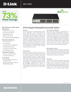


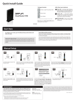
© Copyright 2026