
Features/ Benefits (cont)
Product Data 19XL 50/60 Hz Hermetic Centrifugal Liquid Chiller HCFC-22 — 300 to 600 Nominal Tons (1055 to 2110 kW) HFC-134a — 200 to 530 Nominal Tons (700 to 1865 kW) The 19XL is the most technologically advanced chiller available. Its innovative combination of advancements in compression, heat exchange, and direct digital control technologies result in an efficient, reliable, and flexible design. Features/Benefits • The 19XL hermetic centrifugal liquid chiller furnishes a choice of environmentally acceptable HCFC-22 or HFC-134a refrigerants; provides high efficiency operation; and, due to its modular design, is ideally suited for add-on and replacement applications. • The 19XL is the only centrifugal chiller available that can utilize either HCFC-22 or HFC-134a. This enhances the 19XL’s usefulness by allowing for the future conversion from HCFC-22 to HFC-134a, should HCFC-22 become unavailable. Flexibility makes the 19XL the ideal choice for your water chilling application today. • Expensive refrigerant monitors and add-on containment devices are not required when using 19XLs with HCFC-22 or HFC-134a. Copyright 1994 Carrier Corporation Form 19XL-3PD The positive pressure design: Reduces the size of the chiller by up to 35% as compared to lowpressure designs, resulting in lower floor space requirements and easier installation. Allows for easier installation within confined plant rooms when compared to similar chillers of equal capacity. This is due to its modular construction and smaller components. Eliminates the need for a purge unit, which reduces refrigerant loss and eliminates purge vent and water piping. Fulfills ASME refrigerant side construction requirements through rigorous pressure testing and a design that ensures a leak tight assembly. Allows for storage of refrigerant in the chiller during servicing with the addition of liquid line and compressor discharge isolation valves. pact design. Water side and refrigerant side tube enhancements reduce the overall resistance to heat transfer, resulting in improved heat transfer efficiency. Optimizing tube spacing allows peak heat transfer efficiency to be achieved when using the new advanced tube surfaces. Integral FLASC (Flash Subcooler) cools the condensed liquid refrigerant to a lower temperature; consequently increasing the refrigeration effect and resulting in reduced compressor power consumption. Variable refrigerant metering ensures a liquid seal at all operating conditions to eliminate performance losses from unintentional hot gas bypass. Direct Digital Controls: Precise chilled water temperature control is maintained by the microprocessor controller which accurately positions the compressor inlet guide vanes in response to changes in coolReduced operating costs ing load. are achieved through Occupancy schedules can be proadvancements in three key grammed into the controller to ensure technologies: that the chiller only operates when cooling is required. Compression: Tunnel diffuser, originally developed Ramp loading ensures a smooth pulldown of water loop temperature through the use of jet engine techwhile preventing a rapid increase nology, is now utilized by Carrier to in compressor power consumption increase centrifugal compressor peak operating efficiency. Higher efficiencies during the pulldown period. are possible by reducing friction losses Demand limiting is included to limit through the diffuser section of the the power draw of the chillers durcompressor. ing peak loading conditions. When incorporated into the Carrier Comfort New impeller with aerodynamically Network (CCN) building automation contoured blade profiles, high back system, a red line command will hold sweep blades, and intermediate splitall chillers at their present capacity ter blades improves the efficiency and prevent any other chillers from of refrigerant compression. starting. If a loadshed signal is received, Reduced mechanical losses and increased efficiency are achieved by the compressors are unloaded to avoid high demand charges whenever optimizing the amount of oil required possible. in the gear mesh, reducing friction in the journal bearings, reducing thrust Chilled water reset can be done manually or automatically from the loads, and streamlining the motor building management system which rotor to reduce windage losses. saves energy when warmer chilled High efficiency hermetic water can be utilized. motors cooled by liquid refrigerant With the addition of the Chillerreduce the electrical losses of the visor chiller plant management compressor. controller, the entire chiller plant, Heat Exchange: including chillers, pumps, valves and The latest heat transfer technolcooling towers, is automatically ogy was used to improve tube surface controlled to reduce the overall plant efficiency, while maintaining a compower consumption. Multiple chill2 ers are sequenced to ensure the lowest possible power consumption during reduced loading conditions. Increased reliability, resulting in less downtime and longer life, is achieved through the use of: The hermetic compressor eliminates shaft seals and associated refrigerant and oil leakage, as well as motor heat rejection to the plant room. Both faults are characteristic of open compressor designs. The single stage design eliminates additional moving parts such as second-stage adjustable guide vanes and multiple FLASCs, which are characteristic of some multistage compressors. Steel backed, babbitt lined, compressor sleeve bearings and a Kingsbury-type, self-leveling thrust bearing increase reliability. Cool-running hermetic motors have been proven reliable through more than 25 years of service. Stationary tunnel diffuser requires no moving or wearing parts, which further enhances reliability. Microprocessor controls eliminate the need for pressure and temperature switches and pressure gages. Circuit boards are encased in plastic modules to eliminate damage and abuse. Microprocessor controls simplify use, improve chiller protection, reduce troubleshooting time, and provide additional information to the operator. The controls feature a: 16 line by 40 character display which provides ‘‘all in one glance’’ access to key chiller operating data and simplifies use by eliminating ‘‘coded’’ messages. It displays over 125 operating and diagnostic conditions to reduce troubleshooting time. Microprocessor monitors over 100 functions to protect the chiller from abnormal conditions. 365-day real time clock allows the operator to program a yearly schedule for the week, weekends, and holidays. Features/Benefits (cont) 19XL HERMETIC CENTRIFUGAL LIQUID CHILLER • Compact, positive-pressure design uses either HCFC-22 or HFC-134a, and eliminates need for purge units, expensive refrigerant monitors, and add-on containment devices • High efficiency design for air-conditioning and light brine chilling applications • Ideal for replacement and add-on jobs due to modular bolt-together construction OPTIONAL UNIT MOUNTED STARTER • Available in wye delta and solid-state low-voltage designs • Single point power connection reduces installation time and cost • Fully tested to ensure reliability prior to shipment from the factory TAKE APART DESIGN • Flanged/bolted design allows easy disassembly and reassembly for rigging into confined plant rooms • Modular design reduces disassembly time and cost HERMETIC SINGLE STAGE HIGH EFFICIENCY COMPRESSOR • High efficiency, single-stage impeller and tunnel diffuser reduce operating costs • Hermetic design eliminates disposal problems associated with oil leakage through open compressor shaft seals and also eliminates motor heat rejected to plant room • Single-stage design simplifies servicing and reduces maintenance costs • Steel-backed, babbitt lined, journal bearings and Kingsbury-type thrust bearing increase reliability 3 Features/Benefits (cont) MICROPROCESSOR CONTROLS • 16 line by 40 character LCD display • ‘‘All in one glance’’ access to key chiller operating data • Monitors over 100 functions and conditions • Displays over 125 operating and diagnostic conditions • Carrier Comfort Network (CCN) compatible INTEGRAL COMPRESSOR LUBRICATION SYSTEM • Refrigerant-cooled oil cooler eliminates auxiliary water piping and simplifies installation • Lube system ‘‘built-into’’ compressor housing eliminates cutting oil lines if compressor is removed during installation or servicing • Oil filter may be changed with refrigerant remaining in the chiller which reduces service time and cost HEAT EXCHANGERS • ASME (American Society of Mechanical Engineers) refrigerant-side construction • Available with 150 psig (1034 kPa) or 300 psig (2068 kPa) nozzle-in-head or marine waterboxes • High performance internally and externally enhanced tubes • Tubing roller expanded into double grooved, tube sheet holes improves reliability • Patented condenser FLASC (Flash Subcooler) increases refrigeration effect and chiller efficiency 4 Features/ Benefits (cont) Battery backup provides protection during power failures and eliminates time consuming control reconfiguration. Alarm file maintains the last 25 time and date stamped alarm and alert messages in memory to reduce troubleshooting time and cost. Capacity override mode keeps the chiller on line to reduce nuisance shutdowns. This function unloads the compressor whenever key safety limits are approached. An automated controls test can be executed prior to start-up to verify that the entire control system is functioning properly. Optional modules offer unique control expandability — chilled water reset and demand limit from remote sources and more. Table of contents Page Features/Benefits . . . . . . . . . . . . . . . . . . . . . . . . . . . . . . . . . . . . . . . . . . . . . . . . . 1-6 Model Number Nomenclature . . . . . . . . . . . . . . . . . . . . . . . . . . . . . . . . . . . . . . . . .5 Machine Components . . . . . . . . . . . . . . . . . . . . . . . . . . . . . . . . . . . . . . . . . . . . . . . 7 Options and Accessories . . . . . . . . . . . . . . . . . . . . . . . . . . . . . . . . . . . . . . . . . . . . . 8 Physical Data . . . . . . . . . . . . . . . . . . . . . . . . . . . . . . . . . . . . . . . . . . . . . . . . . . . . . 8,9 Dimensions . . . . . . . . . . . . . . . . . . . . . . . . . . . . . . . . . . . . . . . . . . . . . . . . . . . . . . . 10 Performance Data . . . . . . . . . . . . . . . . . . . . . . . . . . . . . . . . . . . . . . . . . . . . . . . 11-16 Typical Piping and Wiring . . . . . . . . . . . . . . . . . . . . . . . . . . . . . . . . . . . . . . . . 16,17 Electrical Data . . . . . . . . . . . . . . . . . . . . . . . . . . . . . . . . . . . . . . . . . . . . . . . . . . . . 18 Controls . . . . . . . . . . . . . . . . . . . . . . . . . . . . . . . . . . . . . . . . . . . . . . . . . . . . . . . . 19-24 Typical Field Wiring . . . . . . . . . . . . . . . . . . . . . . . . . . . . . . . . . . . . . . . . . . . . . . 25-28 Application Data . . . . . . . . . . . . . . . . . . . . . . . . . . . . . . . . . . . . . . . . . . . . . . . . .29-32 Guide Specifications . . . . . . . . . . . . . . . . . . . . . . . . . . . . . . . . . . . . . . . . . . . . . 33-38 Model number nomenclature Additional features simplify installation and reduce installation time and cost: Refrigerant-cooled oil cooler eliminates auxiliary water piping. Optional unit-mounted starters provide single point power connection and are fully tested prior to shipment from the factory. Factory testing before shipment provides peace of mind while protecting your chiller investment: ASME inspections of all pressure vessels occur at major points of assembly. ASME rated materials and processes result in the ‘‘U’’ stamp, a sign of pressure vessel integrity. Compressors are 100% runtested before mounting as an extra quality step. Hydrostatic, vacuum and pressure testing of the assembled chillers ensures leak integrity. Controls and optional unitmounted starter are tested after mounting to verify proper electrical functioning. Canadian Standards Association ASME ‘U’ Stamp ARI (Air Conditioning and Refrigeration Institute) Performance Certified 5 Features/Benefits (cont) 19XL Refrigeration Cycle The compressor continuously draws refrigerant vapor from the cooler, at a rate set by the amount of guide vane opening. As the compressor suction reduces the pressure in the cooler, the remaining refrigerant boils at a fairly low temperature (typically 38 to 42 F [3 to 6 C]). The energy required for boiling is obtained from the water flowing through the cooler tubes. With heat energy removed, the water becomes cold enough for use in an air-conditioning circuit or process liquid cooling. After taking heat from the water, the refrigerant vapor is compressed. Compression adds still more heat energy and the refrigerant is quite warm (typically 98 to 102 F [37 to 40 C]) when it is discharged from compressor into condenser. Relatively cool (typically 65 to 90 F [18 to 32 C]) water flowing into the condenser tubes removes heat from the refrigerant and the vapor condenses to liquid. The liquid refrigerant passes through orifices into the FLASC (Flash Subcooler) chamber. Since the FLASC chamber is at a lower pressure, part of the liquid refrigerant flashes to vapor, thereby cooling the remaining liquid. The FLASC vapor is recondensed on the tubes which are cooled by entering condenser water. The liquid drains into a float valve chamber between the FLASC chamber and cooler. Here a float valve forms a 19XL REFRIGERATION CYCLE 6 liquid seal to keep FLASC chamber vapor from entering the cooler. When liquid refrigerant passes through the valve, some of it flashes to vapor in the reduced pressure on the cooler side. In flashing, it removes heat from the remaining liquid. The refrigerant is now at a temperature and pressure at which the cycle began. Machine components FRONT VIEW 1 2 3 4 5 6 7 8 9 10 11 12 13 — — — — — — — — — — — — — 14 15 16 17 18 19 20 21 22 — — — — — — — — — Unit-Mounted Starter (Optional) Refrigerant Filter/Drier Refrigerant Dry-Eye Indicator Motor Sight Glass Refrigerant Motor Drain Oil Filter Access Cover Refrigerant Oil Cooler Gear/Bearing Inspection Port Oil Level Sight Glasses Guide Vane Actuator Typical Flange Connection Local Interface Display Control Panel ASME (American Society of Mechanical Engineers) Nameplate, Cooler Take-Apart, Rabbet-Fit Connector (Lower) Refrigerant Charging Valve Oil Drain Valve Auxiliary Power Panel Typical Waterbox Drain Port Cooler Return-End Waterbox Cover ASME Nameplate Condenser Condenser Return-End Waterbox Cover Take-Apart, Rabbet-Fit Connector (Upper) REAR VIEW 23 24 25 26 27 28 29 30 31 32 33 34 35 36 37 38 39 — — — — — — — — — — — — — — — — — Pumpdown Valve Cooler Auto-Reset, Relief Valves Machine Identification Nameplate Cooler Pressure Transducer Suction Elbow Oil Reclaim Demister Line Oil Temperature Thermistors Condenser Isolation Valve 24 Volt Access Door, Starter Low-Voltage Access Door, Starter Amp/Volt Gages Condenser Pressure Transducer Linear Float Valve Chamber Cooler Refrigerant Isolation Valve Condenser Auto Reset Relief Valves Condenser In/Out Temperature Thermistors Cooler In/Out Temperature Thermistors 7 Options and accessories ITEM Shipped Factory Charged with HCFC-22 or HFC-134a Refrigerant Full Insulation (except waterbox covers) 300 psig (1034 kPa) Nozzle-In-Head Waterboxes One, 2 or 3 Pass Heat Exchangers 300 psig (2068 kPa) Marine Waterboxes Flanged Cooler and Condenser Water Nozzles Medium Voltage Motors Export Crating Hot Gas Bypass Unit Mounted Low-Voltage Wye-Delta or Solid-State Starter with: — Normal I.C. Circuit Breaker — High I.C. Circuit Breaker** — 3-Phase Ammeter/Voltmeter — Lightning/Surge Arrestor Package — kW Transducer — 3 Phase Under/Over Voltage Protection — Ground Fault Protection** — Phase Failure/Reversal/Unbalance Protection** — Power Factor Correction Capacitors Controls Option Module .035-in. Wall Tubes, Enhanced .028 or .035-in. Wall Tubes, Not Enhanced .028 or .035-in. Wall Tubes, Cupronickel Factory Performance Test Option Module Upgrade Kit Discharge Line Sound Reduction Kit Storage Tank and Pumpout Unit Stand Alone Pumpout Unit Soleplate Package Spring Isolators Spare Sensor with Lead Flow Switch, Differential Pressure Type I.C. — Interrupting Capacity *Factory installed. OPTION* X X X X X X X X X X X X X X X X X X X X X X X X ACCESSORY† X X X X X X X X †Field installed. **Indicates an option on wye-delta starter, but a standard feature on solid-state starter. Physical data COMPRESSOR/MOTOR WEIGHTS ENGLISH SI MOTOR Stator Weight (lb) Rotor Weight (lb) End Bell Compressor Stator Weight (kg) Rotor Weight (kg) End Bell Compressor SIZE Weight (lb) 60 Hz 50 Hz 60 Hz 50 Hz Cover (lb) Weight (kg) 60 Hz 50 Hz 60 Hz 50 Hz Cover (kg) CB 2660 1135 1147 171 233 250 1208 515 520 78 106 114 CC 2660 1143 1150 197 239 250 1208 518 522 90 109 114 CD 2660 1153 1213 234 252 250 1208 523 551 106 114 114 CE 2660 1162 1227 237 255 250 1208 528 557 108 116 114 CL 2660 1202 1283 246 270 250 1208 546 582 112 123 114 CM 2660 1225 1308 254 275 250 1208 556 594 115 125 114 CN 2660 1276 1341 263 279 250 1208 579 609 119 127 114 CP 2660 1289 1356 266 284 250 1208 585 616 121 129 114 CQ 2660 1306 1363 273 287 250 1208 593 619 124 130 114 CR 2660 1335 1384 282 294 250 1208 606 628 128 133 114 NOTE: For medium voltage motors add 85 lbs (39 kg) to above for 60-Hz motors and 145 lbs (66 kg) for 50-Hz motors. Total compressor/motor weight is the sum of the compressor, stator, rotor, and end bell cover weight. Compressor weight includes suction and discharge elbow weights. COMPONENT WEIGHTS COMPONENT Suction Elbow* Discharge Elbow* Control Cabinet† Optional Mounted Starter** lb 54 46 30 500 kg 25 21 14 227 *Included in total compressor weight. †Included in total cooler weight. **Weight of optional factory-mounted starter is not included and must be added to heat exchanger weights. 8 HEAT EXCHANGER WEIGHTS ENGLISH SI Rigging Wt (lb)* Machine Charge (lb) Rigging Wt (kg)* Machine Charge (kg) CODE Refrigerant† Water Refrigerant* Water Cooler Condenser Cooler Condenser Only Only Only Cooler Condenser Cooler Condenser Only Cooler Condenser Cooler Condenser 40 5154 4643 920 350 445 465 2340 2108 417 159 202 211 41 5275 4771 990 350 485 515 2395 2166 449 159 220 234 42 5418 4909 1050 350 535 565 2460 2229 476 159 243 257 43 5577 5064 1100 350 590 625 2532 2299 499 159 268 284 50 6730 6413 1300 350 660 700 3055 2912 590 159 300 318 51 6927 6584 1350 350 725 765 3145 2989 612 159 329 347 52 7140 6780 1430 350 800 840 3242 3078 649 159 363 381 53 7359 7005 1500 350 870 920 3341 3180 681 159 395 418 55 8220 8008 1840 490 870 935 3728 3632 835 222 395 424 56 8517 8260 1910 490 960 1025 3863 3746 866 222 436 465 57 8836 8560 2020 490 1070 1130 4007 3882 916 222 485 513 58 9164 8900 2120 490 1170 1245 4156 4037 961 222 531 565 *Rigging weights are for standard tubes of standard wall thickness. For special tubes refer to the 19XL Computer Selection Program. †Refrigerant charge listed is the same for both HCFC-22 and HFC-134a. ADDITIONAL WEIGHT FOR MARINE WATERBOXES* HEAT EXCHANGER FRAME, PASS FRAME FRAME FRAME FRAME 4, 4, 5, 5, 2 1 2 1 PASS & 3 PASS PASS & 3 PASS ENGLISH Rigging Wt (lb) Water Wt (lb) Cooler Condenser Cooler Condenser 1115 660 575 425 2030 1160 1155 845 1220 935 730 535 2240 1705 1460 1070 SI Rigging Wt (kg) Cooler Condenser 506 300 922 527 554 424 1017 774 Water Wt (kg) Cooler Condenser 261 193 524 384 331 243 663 486 *Add to heat exchanger weights for total weight. WATERBOX COVER WEIGHTS* ENGLISH (lb) FRAME 4, STD NOZZLES WATERBOX DESCRIPTION 150 psig 300 psig NIH, 1 Pass Cover 284 414 NIH, 2 Pass Cover 285 411 NIH, 3 Pass Cover 292 433 COOLER NIH, Plain End Cover 243 292 MWB Cover CS 621 Plain End Cover CS 482 NIH, 1 Pass Cover 306 446 NIH, 2 Pass Cover 288 435 NIH, 3 Pass Cover 319 466 CONDENSER NIH, Plain End Cover 226 271 MWB Cover CS 474 Plain End Cover CS 359 HEAT EXCHANGER FRAME 4, FLANGED 150 psig 300 psig 324 491 341 523 309 469 243 292 CS 621 CS 482 346 523 344 547 336 502 226 271 CS 474 CS 359 FRAME 5, STD NOZZLES 150 psig 300 psig 412 578 410 573 423 602 304 426 CS 766 CS 471 373 472 368 469 407 493 271 379 CS 590 CS 428 FRAME 5, FLANGED 150 psig 300 psig 452 655 466 685 440 638 304 426 CS 766 CS 471 413 549 428 541 419 549 271 379 CS 590 CS 428 FRAME 5, STD NOZZLES 1034 kPa 2068 kPa 187 262 186 260 192 273 138 193 CS 348 CS 214 169 214 167 213 185 224 123 172 CS 268 CS 194 FRAME 5, FLANGED 1034 kPa 2068 kPa 205 297 212 311 200 290 138 193 CS 348 CS 214 188 249 194 246 190 249 123 172 CS 268 CS 194 SI (kg) FRAME 4, STD NOZZLES WATERBOX DESCRIPTION 1034 kPa 2068 kPa NIH, 1 Pass Cover 129 188 NIH, 2 Pass Cover 129 187 NIH, 3 Pass Cover 133 197 COOLER NIH, Plain End Cover 110 133 MWB Cover CS 282 Plain End Cover CS 219 NIH, 1 Pass Cover 139 202 NIH, 2 Pass Cover 131 197 NIH, 3 Pass Cover 145 212 CONDENSER NIH, Plain End Cover 103 123 MWB Cover CS 215 Plain End Cover CS 163 HEAT EXCHANGER CS — Contact Syracuse MWB — Marine Water Box NIH — Nozzle-In-Head FRAME 4, FLANGED 1034 kPa 2068 kPa 147 223 155 237 140 213 110 133 CS 282 CS 219 157 237 156 248 153 228 103 123 CS 215 CS 163 *These weights are for reference only. The 150 psig (1034 kPa) standard waterbox cover weights have been included in the heat exchanger weights shown above. 9 Dimensions HEAT EXCHANGER (Cooler and Condenser Size) 40-43 50-53 55-58 A (Length) 2 Pass* 1 or 3 Pass† ft-in. mm ft-in. mm 13-73⁄4 4159 14-31⁄4 4350 13-8 4166 14-33⁄4 4362 18-41⁄2 5601 19-01⁄4 5798 HEAT EXCHANGER (Cooler and Condenser Size) 40-53 55-58 B (Width) ft-in. 5-53⁄4 6-01⁄4 6-01⁄4 mm 1670 1835 1835 NOZZLE SIZE (in.) (Nominal Pipe Size) C (Height) ft-in. 6-85⁄8 7-21⁄8 7-21⁄8 mm 2048 2188 2188 1-Pass 10 10 10 2-Pass 8 8 8 3-Pass 6 6 6 A (Length With Marine Waterbox — Not Shown) 2 Pass* 1 or 3 Pass† ft-in. mm ft-in. mm 14-95⁄8 4512 16-51⁄2 5017 5947 21-51⁄2 6541 19-61⁄8 *Assumes both cooler and condenser nozzles on same end of chiller. †1 or 3 pass length applies if either (or both) cooler or condenser is a 1 or 3 pass design. MOTOR SERVICE CLEARANCE CLEARANCE D ft-in. 4-0 10 mm 1219 NOTES: 1. Service access should be provided per American Society of Heating, Refrigeration, and Air Conditioning Engineers (ASHRAE) 15, latest edition, National Fire Protection Association (NFPA) 70, and local safety code. 2. Allow at least 3 ft (915 mm) overhead clearance for service rigging. 3. Certified drawings available upon request. Performance data COOLER PRESSURE DROP 19XL, 1 PASS COOLER, NOZZLE-IN-HEAD TURBO-B II, STANDARD WALL TUBING FRESH WATER AT 50 F 19XL, 2 PASS COOLER, NOZZLE-IN-HEAD TURBO-B II, STANDARD WALL TUBING FRESH WATER AT 50 F NOTES: 1. Hx-- designations are cooler heat exchanger sizes. 2. To determine pressure drops more accurately and to compensate for actual water temperature, use the computerized selection service available through your local Carrier Sales office. 11 Performance data (cont) COOLER PRESSURE DROP 19XL, 3 PASS COOLER, NOZZLE-IN-HEAD TURBO-B II, STANDARD WALL TUBING FRESH WATER AT 50 F 19XL; 1, 2, 3 PASS COOLER; NOZZLE-IN-HEAD TURBO-B II; STANDARD WALL TUBING FRESH WATER AT 50 F; FRAME 55-58 NOTES: 1. Hx-- designations are cooler heat exchanger sizes. 2. To determine pressure drops more accurately and to compensate for actual water temperature, use the computerized selection service available through your local Carrier Sales office. 12 CONDENSER PRESSURE DROP 19XL, 1 PASS CONDENSER, NOZZLE-IN-HEAD SPIKE FIN, STANDARD WALL TUBING FRESH WATER AT 90 F 19XL, 2 PASS CONDENSER, NOZZLE-IN-HEAD SPIKE FIN, STANDARD WALL TUBING FRESH WATER AT 90 F NOTES: 1. Hx-- designations are cooler heat exchanger sizes. 2. To determine pressure drops more accurately and to compensate for actual water temperature, use the computerized selection service available through your local Carrier Sales office. 13 Performance data (cont) CONDENSER PRESSURE DROP 19XL, 3 PASS CONDENSER, NOZZLE-IN-HEAD SPIKE FIN, STANDARD WALL TUBING FRESH WATER AT 90 F 19XL, 1, 2, 3 PASS CONDENSER; NOZZLE-IN-HEAD SPIKE FIN; STANDARD WALL TUBING FRESH WATER AT 90 F; FRAME 55-58 NOTES: 1. Hx-- designations are cooler heat exchanger sizes. 2. To determine pressure drops more accurately and to compensate for actual water temperature, use the computerized selection service available through your local Carrier Sales office. 14 HEAT EXCHANGER MIN/MAX FLOW RATES* ENGLISH (Gpm) COOLER Frame 1 PASS Size 40 41 42 43 50,55 51,56 52,57 53,58 Min 590 666 754 851 921 1041 1173 1305 CONDENSER Frame Size 40 41 4 42 43 50,55 51,56 5 52,57 53,58 Min 613 692 785 886 976 1089 1216 1362 4 5 2 PASS Max 2358 2664 3016 3403 3684 4165 4693 5222 Min 295 333 377 425 461 521 587 653 Max 2454 2769 3140 3546 3906 4356 4863 5448 Min 307 346 393 443 488 545 608 681 1 PASS 3 PASS Max 1179 1332 1508 1701 1842 2083 2347 2611 Min 197 222 251 284 307 347 391 435 Max 1227 1384 1570 1773 1953 2178 2431 2724 Min 204 231 262 295 325 363 405 454 Max 74.4 84.0 95.1 107.3 116.2 131.4 148.1 164.7 Min 12.4 14.0 15.9 17.9 19.4 21.9 24.7 27.5 Max 77.4 87.3 99.1 111.8 123.2 137.4 153.4 171.9 Min 12.9 14.6 16.5 18.6 20.5 22.9 25.6 28.6 2 PASS Max 786 888 1005 1134 1228 1388 1564 1741 3 PASS Max 818 923 1047 1182 1302 1452 1621 1816 SI (L/s) COOLER Frame 1 PASS Size 40 41 42 43 50,55 51,56 52,57 53,58 Min 37.2 42.0 47.6 53.7 58.1 65.7 74.0 82.4 CONDENSER Frame Size 40 41 4 42 43 50,55 51,56 5 52,57 53,58 Min 38.7 43.7 49.5 55.9 61.6 68.7 76.7 85.9 4 5 2 PASS Max 148.8 168.0 190.3 214.7 232.4 262.8 296.1 329.4 Min 18.6 21.0 23.8 26.8 29.1 32.9 37.0 41.2 Max 154.8 174.7 198.1 223.7 246.4 274.8 306.8 343.7 Min 19.4 21.8 24.8 28.0 30.8 34.4 38.3 43.0 1 PASS 3 PASS 2 PASS Max 49.6 56.0 63.4 71.6 77.5 87.6 98.7 109.8 3 PASS Max 51.6 58.2 66.0 74.6 82.1 91.6 102.3 114.6 *Flow rates based on standard tubes, cooler, and condenser. Minimum flow based on tube velocity of 3 ft/sec (.91 m/sec); maximum based on 12 ft/sec (3.66 m/sec). AUXILIARY RATINGS (3 Phase, 50/60 Hz) ITEM AVERAGE kW OIL PUMP 1.35 1.35 1.35 1.50 1.50 DESIGN CENTER VOLTAGE V-PH-HZ 220-3-60 430-3-60 563-3-60 230-3-50 393-3-50 AUXILIARY RATINGS (115/230 Volt, 1 Phase, 50/60 Hz) MIN/MAX MOTOR VOLTAGE INRUSH kva SEALED kva 200/240 380/480 507/619 220/240 346/440 9.34 9.09 24.38 11.15 8.30 1.65 1.60 2.08 1.93 1.76 ITEM POWER CONTROLS OIL SUMP HEATER 24 V DC 115-230/1/50-60 SEALED kva 0.16 — AVERAGE WATTS 160 1200 NOTES: 1. Transmission oil heater only operates when the compressor is off. 2. Power to oil heater/controls must be on circuits that can provide continuous service when the compressor is disconnected. NOTES: FLA = Sealed kva * 1000/= 3 * volts LRA = Inrush kva * 1000/=3 * volts 15 Performance data (cont) Compressor motor controllers Capacitors/power factors Compressor motors, as well as controls and accessories, require the use of starting equipment systems specifically designed for 19XL Chillers. Refer to Carrier Engineering Requirement Z-375 or consult Carrier regarding design information for the selection of controllers. Power factor considerations may indicate use of capacitors. Properly sized capacitors improve power factors, especially at part load. The 19XL Computer Selection Program can select the proper capacitor size required for your application. Typical piping and wiring 19XL CHILLER WITH OPTIONAL UNIT-MOUNTED STARTER TO LOAD 1 2 3 4 5 6 16 — — — — — — LEGEND Chilled Water Pump Starter Condenser Water Pump Starter Cooling Tower Fan Starter Condenser Water Pump Chilled Water Pump Disconnect NOTES: 1. Wiring and piping shown are for general point-of-connection only and are not intended to show details for a specific installation. Certified field wiring and dimensional diagrams are available on request. 2. All wiring must comply with applicable codes. 3. Refer to Carrier System Design Manual for details regarding piping techniques. 4. Wiring not shown for optional devices such as: • Remote Start/Stop • Remote Alarm • Optional Safety Device • 4 to 20 mA Resets • Optional Remote Sensors 19XL CHILLER WITH FREE-STANDING STARTER LEGEND Chilled Water Pump Starter Condensing Water Pump Starter Cooling Tower Fan Starter Condenser Water Pump Chilled Water Pump Disconnect Oil Pump Disconnect (See Note 5) Freestanding Compressor Motor Starter 9 — Compressor Motor Terminal Box 10 — Chiller Power Panel 11 — Vents 1 2 3 4 5 6 7 8 — — — — — — — — NOTES: 1. Wiring and piping shown are for general point-of-connection only and are not intended to show details for a specific installation. Certified field wiring and dimensional diagrams are available on request. 2. All wiring must comply with applicable codes. 3. Refer to Carrier System Design Manual for details regarding piping techniques. 4. Wiring not shown for optional devices such as: • Remote Start/Stop • Remote Alarm • Optional Safety Device • 4 to 20 mA Resets • Optional Remote Sensors 5. Oil pump disconnect may be located within the enclosure of Item 8 — Freestanding Compressor Motor Starter. 17 Electrical data MOTOR MOTOR ELECTRICAL SIZE CHARACTERISTICS Max IkW 200 v RLA per IkW 3.32 CB LRA Star 155 850 LRA Delta 2656 RLA per IkW 3.35 CC LRA Star 171 1044 LRA Delta 3262 RLA per IkW 3.28 CD LRA Star 200 1135 LRA Delta 3545 RLA per IkW 3.28 CE LRA Star 219 1395 LRA Delta 4359 RLA per IkW 3.28 CL LRA Star 243 1275 LRA Delta 3984 RLA per IkW 3.32 CM LRA Star 267 1349 LRA Delta 4215 RLA per IkW 3.28 CN LRA Star 295 1644 LRA Delta 5138 RLA per IkW 3.24 CP LRA Star 323 1607 LRA Delta 5023 RLA per IkW 3.28 CQ LRA Star 360 1912 LRA Delta 5976 RLA per IKW 3.26 CR LRA Star 410 2836 LRA Delta 8864 lkW LRA OLTA RLA — — — — 60 Hz MOTORS Low Volts 2.92 763 2385 3.02 964 3012 2.85 1012 3163 2.85 1044 3263 2.85 1173 3665 2.89 1422 4443 2.85 1333 4167 2.82 1430 4468 2.85 1639 5121 2.80 2125 6640 1.92 520 1626 1.75 520 1626 1.83 676 2112 1.73 622 1945 1.73 749 2340 1.74 841 2628 1.73 865 2704 1.71 851 2659 1.73 948 2963 1.72 1423 4447 1.60 524 1638 1.60 553 1729 1.57 617 1929 1.57 606 1893 1.55 708 2212 1.56 825 2577 1.56 874 2731 1.56 859 2684 1.56 1064 3325 1.56 1211 3785 1.46 374 1167 1.44 418 1305 1.43 486 1519 1.43 462 1443 1.43 546 1707 1.44 562 1757 1.43 663 2071 1.41 719 2247 1.43 1000 3125 1.42 1199 3748 NOTES: 1. Standard Voltages: Volt 200 230 380 416 460 575 2400 3300 4160 Volt 230 346 400 3000 3300 50 HZ For use on supply voltages 220 to 240 v systems 320 to 360 v systems 380 to 415 v systems 2900 to 3100 v systems 3200 to 3400 v systems Motor nameplates can be stamped for any voltage within the listed supply/voltage range. Chillers shall not be selected at voltages above or below the listed supply voltage range. 18 50 Hz MOTORS Low Volts Medium Volts 230 v 380 v 416 v 460 v 575 v 2400 v 3300 v 4160 v 230 v 346 v 400 v 3000 v 3300 v LEGEND Compressor Motor Power Input (Kilowatts) Locked Rotor Amps Overload Trip Amps (= RLA x 1.08) Rated Load Amps 60 HZ For use on supply voltages 200 to 208 v systems 220 to 240 v systems 360 to 400 v systems 401 to 439 v systems 440 to 480 v systems 550 to 600 v systems 2300 to 2500 v systems 3150 to 3450 v systems 4000 to 4300 v systems Medium Volts 1.21 318 994 1.15 321 1004 1.14 405 1265 1.14 373 1165 1.14 398 1245 1.15 498 1556 1.14 610 1908 1.13 601 1878 1.14 672 2098 1.13 856 2675 .277 — 204 .280 — 226 .274 — 255 .272 — 284 .272 — 281 .272 — 313 .272 — 346 .274 — 378 .274 — 457 .274 — 528 .201 — 149 .203 — 164 .199 — 199 .196 — 210 .200 — 227 .199 — 261 .198 — 287 .200 — 320 .198 — 329 .202 — 414 .160 — 118 .161 — 130 .158 — 147 .155 — 164 .157 — 178 .159 — 198 .156 — 215 .160 — 237 .160 — 268 .157 — 297 2.82 795 2485 2.85 771 2410 2.82 924 2887 2.85 1165 3640 2.82 1197 3740 2.79 1542 4819 2.79 1446 4518 2.82 1534 4794 2.79 1542 4819 2.80 2068 6464 1.87 545 1702 1.90 593 1852 1.87 673 2102 1.90 780 2436 1.87 812 2536 1.85 833 2603 1.85 854 2670 1.87 1020 3187 1.96 1303 4071 1.87 1440 4500 1.74 480 1501 1.64 462 1443 1.62 563 1761 1.64 665 2078 1.62 721 2252 1.60 730 2280 1.70 896 2800 1.62 951 2973 1.60 951 2973 1.61 1158 3619 .221 — 156 .221 — 167 .212 — 194 .219 — 214 .212 — 241 .220 — 258 .216 — 291 .215 — 325 .213 — 346 .213 — 450 .201 — 150 .201 — 164 .199 — 194 .197 — 212 .196 — 236 .200 — 254 .194 — 285 .197 — 292 .194 — 343 .195 — 438 2. To establish electrical data for your selected voltage, if other than listed voltage, use the following formula: listed voltage RLA = listed RLA x selected voltage listed voltage OLTA = listed OLTA x selected voltage selected voltage LRA = listed LRA x listed voltage EXAMPLE: Find the rated load amperage for a motor listed at 1.14 amps per kW input and 550 volts. 575 RLA = 1.14 x = 1.19 550 Controls Microprocessor controls Microprocessor controls provide the safety, interlock, capacity control, and indications necessary to operate the chiller in a safe and efficient manner. Control system The microprocessor control on each Carrier centrifugal system is factory mounted, wired, and tested to ensure machine protection and efficient capacity control. In addition, the program logic ensures proper starting, stopping, and recycling of the machine and provides a communication link to the Carrier Comfort Network (CCN). Features Control system Component Test and Diagnostic Check Menu-Driven Keypad Interface for Status Display, Set Point Control, and System Configuration CCN Compatible Primary and Secondary Status Messages Individual Start/Stop Schedules for Local and CCN Operation Modes Recall of Up to 25 Alarm/Alert Messages with Diagnostic Help Safety cutouts Bearing Oil High Temperature* Motor High Temperature*† Refrigerant (Condenser) High Pressure*† Refrigerant (Cooler) Low Temperature*† Lube Oil Low Pressure Compressor (Refrigerant) Discharge Temperature* Under Voltage** Over Voltage** Oil Pump Motor Overload Cooler and Condenser Water Flow†† Motor Overload† Motor Acceleration Time Intermittent Power Loss Compressor Starter Faults Compressor Surge Protection* Capacity Control Leaving Chilled Water Control Entering Chilled Water Control Soft Loading Control by Temperature or Load Ramping Guide Vane Actuator Module Hot Gas Bypass Valve Power (Demand) Limiter Auto. Chilled Water Reset Interlocks Manual/Automatic Remote Start Starting/Stopping Sequence Pre-Lube/Post-Lube Pre-Flow/Post-Flow Compressor Starter Run Interlock Oil Pump Interlock Pre-Start Check of Safeties and Alerts Low Chilled Water (Load) Recycle Monitor/Number Compressor Starts and Run Hours Manual Reset of Safeties Indications Chiller Operating Status Message Power-On Pre-Start Diagnostic Check Compressor Motor Amps Pre-Alarm Alert\ Alarm Contact for Remote Alarm Safety Shutdown Messages Elapsed Time (Hours of Operation) Chiller Input kW¶ *These can be configured by user to provide alert indication at user-defined limit. †Override protection: Causes compressor to first unload and then, if necessary, shut down. **Will not require manual reset or cause an alarm if autorestart after power failure is enabled. ††Required: Field or factory supplied flow switch (installed at jobsite). \By display code only. ¶ kW transducer must be supplied in motor starter. 19 Controls (cont) MICROPROCESSOR CONTROL PANEL CONTROL PANEL (Front View) WITH OPTIONS LEGEND 1 — Local Interface Device (LID) Input/ Output Interface Panel Display 2 — Processor Module (PSIO). The PSIO is the Brain of the Product Integrated Controls 3 — Optional 8 input Module for Spare Inputs to Control Interface (one of two available) 4 — Power Transformer 5 — 6-Pack Relay Board 6 — Circuit Breakers (4) 20 LOCAL INTERFACE DEVICE (LID) TYPICAL DISPLAY PANELS Default Display — Displays information most commonly required for chiller operating logs. Two line system status messages inform the operator of mode of operation or any alert or alarm messages. The four ‘‘softkeys’’ allow access to other control functions. Status Screens — Displays readings of every point monitored by the microprocessor. Cooler, condenser, and oil pressure are included in the status screens. Schedule Screen — A user established occupancy schedule can easily be configured for your particular application. A 365-day, real time, battery backed up clock will automatically start and stop the chiller according to your established schedule or based on the buildling master schedule in a CCN system. Set Point Screen — The chilled water and demand limit set points can be entered, stored, viewed, or changed easily from this screen. 21 Controls (cont) LOCAL INTERFACE DEVICE (LID) TYPICAL DISPLAY PANELS Service Screens — The password protected service screens provide an array of information available to the service technician to configure the chiller for your particular application and troubleshoot any problems that may occur. Alarm History File — Stores last 25 alarms or alerts that have occurred along with time and date indication. Allows service technician to quickly review alarm or alert history to identify problems that exist as well as action required to resolve the problem. The Service Configuration Screens — Allow the service technician to configure the controls for your particular application and set override and alert levels for several points monitored by the control system. The Controls Test Screen — Allows access to the various controls tests available to the service technician to quickly identify sources of problems and to get the chiller back on line rapidly. 22 CONTROL SEQUENCE A B C — START INITIATED — Prestart checks made; evaporator pump started. — Condenser water pump started (5 seconds after A). — Water flows verified (one minute to 5 minutes maximum). Chilled water temperatures checked against control point. Guide vanes checked for closure. Oil pump started; tower fan control enabled. D — Oil pressure verified (fifteen seconds minimum 300 seconds maximum after C). E — Compressor motor starts, compressor ontime and service ontime starts, 15-minute inhibit timer starts (10 seconds after D). F — SHUTDOWN INITIATED — Compressor motor stops, compressor ontime and service ontime stops, 3-minute inhibit timer starts. G — Oil pump and evaporator pumps deenergized (60 seconds after F). Condenser pump and tower fan control may continue to operate if condenser pressure is high. Evaporator pump may continue if in RECYCLE mode. O/A — Restart permitted (both inhibit timers expired) (minimum of 15 minutes after E; minimum of 3 minutes after F). 23 Controls (cont) Control sequence To start: Local start-up (manual start-up) is initiated by pressing the LOCAL menu softkey which is indicated on the default local interface device (LID) screen. Time schedule 01 must be in the occupied mode and the internal 15-minute start-to-start and the 3-minute stop-to-start inhibit timers must have expired. All pre-start safeties are checked to verify that all pre-start alerts and safeties are within limits (if one is not an indication of the fault will be displayed and the start aborted). The signal is sent to start the chilled water pump. Five seconds later, the condenser water pump is energized. One minute later the controls check to see if flow has been confirmed by the closure of the chilled water and condenser water flow switches. If not confirmed, it will continue to monitor flows for a maximum of five minutes. If satisfied, it checks the chilled water temperature against the control point. If the temperature is less than or equal to the chilled water control point the condenser water pump will turn off and the controls will go into a recycle mode. If the water/brine temperature is high enough the start-up sequence continues on to check the guide vane position. If the guide vanes are more than 6% open, start-up waits until the vanes are closed. If the vanes are closed and the oil pump pressure is less than 3 psi (21 kPa), the oil pump and tower fan relay will be energized. The controls will wait 15 seconds for the oil pressure to reach a maximum of 18 psi (924 kPa). After oil pressure is verified, the controls wait 15 seconds. Then the compressor start relay is energized to start the compressor. Compressor ontime and service ontime ‘‘timers’’ start and the 15-minute start-to-start timer will start 15 seconds after oil pressure was verified. Once started: The controls will enter the ramp loading mode to slowly open the guide vanes to prevent a rapid 24 increase in compressor power consumption. Once completed the controls will enter the capacity control mode. Any failure, after the compressor is energized, that results in a safety shutdown will energize the alarm light, advance the starts in 12 hours counter by one, and display the applicable shutdown status on the liquid-crystal display (LCD) screen. Shutdown sequence: Shutdown of the chiller can occur if any of the following events happen: • The stop button is pressed for at least one second • A recycle shutdown was initiated • Time schedule has gone into unoccupied mode • Machine protective limit has been reached and machine is in alarm • The start/stop status is overridden to stop from the CCN network or LID Once the controls are placed in shutdown mode the shutdown sequence first stops the compressor by deactivating the start relay. The guide vanes are then brought to the closed position. Compressor ontime and service ontime stops. The oil pump relay and chilled water/brine pump are shut down 60 seconds after the compressor stops. The condenser water pump will be shut down when the refrigerant temperature or entering condenser water is below preestablished limits. The 3-minute stop-to-start will now start to count down. If the compressor motor load is greater than 10% after shutdown, or the starter contacts remain energized, the oil pump and chilled water pump remain energized and the alarm is displayed. Restart: Restart is permitted after both inhibit timers have expired. If shutdown was due to a safety shutdown the reset button must be depressed prior to restarting the chiller. 19XL TYPICAL FIELD WIRING WITH OPTIONAL UNIT-MOUNTED STARTER Typical field wiring 25 Typical field wiring (cont) 19XL TYPICAL FIELD WIRING WITH OPTIONAL UNIT-MOUNTED STARTER (cont) NOTES: I. GENERAL: 1.0 Starters shall be designed and manufactured in accordance with Carrier Engineering Requirement Z-375. 1.1 All field-supplied conductors, devices, and the field-installation wiring, termination of conductors and devices, must be in compliance with all applicable codes and job specifications. 1.2 The routing of field-installed conduit and conductors and the location of field-installed devices, must not interfere with equipment access or the reading, adjusting, or servicing of any component. 1.3 Equipment installation and all starting and control devices, must comply with details in equipment submittal drawings and literature. 1.4 Contacts and switches are shown in the position they would assume with the circuit deenergized and the chiller shut down. 1.5 WARNING — Do not use aluminum conductors. II. POWER WIRING TO STARTER 2.0 Power conductor rating must meet minimum unit nameplate voltage and compressor motor RLA. When 3 conductors are used: Minimum ampacity per conductor = 1.25 x compressor RLA When 6 conductors are used: Minimum ampacity per conductor = 0.721 x compressor RLA 2.1 Lug adapters may be required if installation conditions dictate that conductors be sized beyond the minimum ampacity required. Solid state starters are provided with: A. Two (2) 0-250 MCM lugs provided per phase for power conductor terminations when compressor motor RLA is 400 amps or less. B. Three (3) 250-500 MCM lugs provided per phase for power conductor terminations when compressor motor RLA is more than 400 amps. Wye-Delta starters are provided with: A. Two (2) 250-500 MCM lugs provided per phase for power conductor terminations when compressor motor RLA is 420 amps or less. B. Two (2) #1-500 MCM lugs provided per phase for power conductor terminals when compressor motor RLA is more than 420 amps. 2.2 Power conductors to starter must enter through top of enclosure. Flexible conduit should be used for the last few feet to the enclosure to provide unit vibration isolation. 2.3 Compressor motor and controls must be grounded by using equipment grounding lugs provided inside unit mounted starter enclosure. III. CONTROL WIRING 3.0 Field-supplied control conductors to be at least 18 AWG or larger. 3.1 Chilled water and condenser water flow switch contacts, optional remote start device contacts, and optional spare safety device contacts, must have 24 vdc rating. Max current is 60 ma, nominal current is 10 ma. Switches with gold plated bifurcated contacts are recommended. 3.2 Remove jumper wire between 12A and 12B before connecting auxiliary safeties between these terminals. 3.3 Pilot relays can control cooler and condenser pump and tower fan motor contactor coil loads rated 10 amps at 115 vac up to 3 amps at 600 vac. Do not use starter control transformer as the power source for pilot relay loads. 3.4 Do not route control wiring carrying 30 v or less within a conduit which has wires carrying 50 v or higher or along side wires carrying 40 v or higher. 26 19XL TYPICAL FIELD WIRING WITH FREE-STANDING STARTER Typical field wiring (cont) 27 Typical field wiring (cont) 19XL TYPICAL FIELD WIRING WITH FREE-STANDING STARTER (cont) NOTES: I. GENERAL: 1.0 Starters shall be designed and manufactured in accordance with Carrier Engineering Requirement Z-375. 1.1 All field-supplied conductors, devices, and the field-installation wiring, termination of conductors and devices, must be in compliance with all applicable codes and job specifications. 1.2 The routing of field-installed conduit and conductors and the location of field-installed devices, must not interfere with equipment access or the reading, adjusting, or servicing of any component. 1.3 Equipment installation and all starting and control devices, must comply with details in equipment submittal drawings and literature. 1.4 Contacts and switches are shown in the position they would assume with the circuit deenergized and the chiller shut down. 1.5 WARNING — Do not use aluminum conductors. 1.6 Installer is responsible for any damage caused by improper wiring between starter and machine. II. POWER WIRING TO STARTER 2.0 Power conductor rating must meet minimum unit nameplate voltage and compressor motor RLA. When 3 conductors are used: Minimum ampacity per conductor = 1.25 x compressor RLA When 6 conductors are used: Minimum ampacity per conductor = 0.721 x compressor RLA 2.1 Lug adapters may be required if installation conditions dictate that conductors be sized beyond the minimum ampacity required. Contact starter supplier for lug information. 2.2 Compressor motor and controls must be grounded by using equipment grounding lugs provided inside starter enclosure. III. CONTROL WIRING 3.0 Field-supplied control conductors to be at least 18 AWG or larger. 3.1 Chilled water and condenser water flow switch contacts, optional remote start device contacts and optional spare safety device contacts, must have 24 vdc rating. Max current is 60 ma, nominal current is 10 ma. Switches with gold plated bifurcated contacts are recommended. 3.2 Remove jumper wire between 12A and 12B before connecting auxiliary safeties between these terminals. 3.3 Pilot relays can control cooler and condenser pump and tower fan motor contactor coil. Loads rated 10 amps at 115 vac up to 3 amps at 600 vac. Do not use starter control transformer as the power source for pilot relay loads. 3.4 Do not route control wiring carrying 30 v or less within a conduit which has wires carrying 50 v or higher or along side wires carrying 50 v or higher. 3.5 Voltage selector switch in machine power panel is factory set for 115 v control and oil heater power source. When 230 v control and oil heater power source is used, set switch to 230 v position. 3.6 Control wiring cables between starter and power panel must be shielded with minimum rating of 600 v, 80 C. Ground shield at starter. 3.7 If optional oil pump circuit breaker is not supplied within the starter enclosure as shown, it must be located within sight of the machine with wiring routed to suit. 28 IV. POWER WIRING BETWEEN STARTER AND COMPRESSOR MOTOR 4.0 Low voltage (600 volts or less) compressor motors have (6) 5⁄89 terminal studs (lead connectors not supplied by Carrier). Either 3 or 6 leads must be run between compressor motor and starter, depending on type of motor starter employed. If only 3 leads are required, jumper motor terminals as follows, 1 to 6, 2 to 4, 3 to 5. Center to center distance between terminals is 2.73 in. Compressor motor starter must have nameplate stamped as to conforming with Carrier requirement ‘‘Z-375.’’ 4.1 When more than one conduit is used to run conductors from starter to compressor motor terminal box, one conductor from each phase must be in each conduit, to prevent excessive heating, (e.g., conductors to motor terminals 1, 2, and 3 in one conduit, and those to 4, 5, and 6 in another). 4.2 Compressor motor power connections can be made through top, bottom, or right side of compressor motor terminal box by rotating the terminal box and using holes cut by contractor to suit conduit. Flexible conduit should be used for the last few feet to the terminal box for unit vibration isolation. Use of stress cones or 12 conductors larger than 500 MCM may require an oversize (special) motor terminal box (not supplied by Carrier). Lead connections between 3-phase motors and their starters must not be insulated until Carrier personnel have checked compressor and oil pump rotation. 4.3 Compressor motor frame to be grounded in accordance with the National Electrical Code (NFPA 70 [National Fire Protection Association]) and applicable codes. Means for grounding compressor motor is 2 pressure connectors for 350 to 800 MCM wire, supplied and located in the back upper and lower right side corners of the compressor motor terminal box. 4.4 Do not allow motor terminals to support weight of wire cables. Use cable supports and strain reliefs as required. 4.5 Use back up wrench when tightening lead connectors to motor terminal studs. Torque to 45 lb-ft max. Application data HEAT EXCHANGER (Cooler/Condenser Size) 40-43 50-53, 55-58 A (ft-in.) 5-53⁄4 6-01⁄4 (mm) 1670.0 1835.2 OPTIONAL ISOLATION NOTES: 1. Dimensions in ( ) are in millimeters. 2. Optional soleplate package includes 4 soleplates, 16 jacking screws and leveling pads. Requires isolation package. 3. Jacking screws to be removed after grout has set. 4. Thickness of grout will vary, depending on the amount necessary to level chiller. Use only pre-mixed non-shrinking grout, Celcote HT-648 or Master Builders 636, 08-11⁄29 (38.1) to 08-21⁄49 (57) thick. TYPICAL ISOLATION STANDARD ISOLATION VIEW B-B ISOLATION WITH ISOLATION PACKAGE ONLY (STANDARD) NOTE: Isolation package includes 4 shear flex pads. 29 Application data (cont) NOZZLE ARRANGEMENTS DRIVE END COMPRESSOR END DRIVE END NOZZLE-IN-HEAD WATERBOXES DRIVE END COMPRESSOR END COMPRESSOR END FRONT VIEW DRIVE END MARINE WATERBOXES COMPRESSOR END FRONT VIEW NOZZLE ARRANGEMENT CODES PASS 1 2 3 COOLER WATERBOXES CONDENSER WATERBOXES In Out Arrangement Code In Out Arrangement Code 8 5 A 11 2 P 5 8 B 2 11 Q 7 9 C 10 12 R 4 6 D 1 3 S 7 6 E 10 3 T 4 9 F 1 12 U WATERBOX NOZZLE SIZES PASS 1 2 3 NOMINAL PIPE SIZE (in.) ACTUAL PIPE ID (in.) ACTUAL PIPE OD (in.) Cooler Condenser Cooler Condenser Cooler Condenser 10 10 10.020 10.020 10.75 10.75 8 8 7.981 7.981 8.625 8.625 6 6 6.065 6.065 6.625 6.625 LEGEND ID — Inside Diameter OD — Outside Diameter NOTE: Standard nozzles have Victaulic grooves. Flanged nozzles are optional. 30 Vent and drain connections Relief-valve discharge pipe sizing With the exception of the cooler vent connection, located in the waterbox shell, all vents and drain connections are found on the waterbox covers. Connection size is 3⁄4-in. FPT. Provide high points of the machine piping system with vents and the low points with drains. If shutoff valves are provided in the main water pipes near the unit, a minimal amount of system water is lost when the heat exchangers are drained. This reduces the time required for drainage and saves on the cost of re-treating the system water. It is recommended that pressure gages be provided at points of entering and leaving water to measure pressure drop through the heat exchanger. Gages may be installed as shown in Pressure Gage Location table. Pressure gages installed at the vent and drain connections do not include nozzle pressure losses. Use a reliable manometer to measure pressure differential when determining water flow. Regular gages are insensitive and do not provide accurate measurement of flow conditions. The 19XL is equipped with 3 relief valves: 2 relief valves are located on all 19XL condensers; 1 relief valve is located on all 19XL coolers. Relief-valve discharge piping size should be calculated per the current version of the ASHRAE 15 code using the tabulated C factors for each vessel shown below: VESSEL Cooler Condenser VESSEL SIZE 40-43 50-53 55-58 40-43 50-53 55-58 RELIEF VALVE SIZE (in. FPT) 1 1 11⁄4 1 1 11⁄4 C FACTOR (lb air/Min) 45.6 54.4 78.8 39.6 46.0 66.9 Carrier further recommends that an oxygen sensor be installed to protect personnel. Sensor should be able to sense the depletion or displacement of oxygen in the machine room below 19.5% volume oxygen per ASHRAE 15, latest edition. PRESSURE GAGE LOCATION NUMBER OF PASSES 1 or 3 2 GAGE LOCATION (Cooler or Condenser) One gage in each waterbox Two gages in waterbox with nozzles Range of application The 19XL refrigeration machine is designed for standard water chilling applications 300 to 600 tons (1055 to 2110 kW) using refrigerant HCFC-22, 200 to 530 tons (700 to 1865 kW) using HFC-134a. ASME stamping All 19XL heat exchangers are constructed in accordance with ASHRAE (American Society of Heating, Refrigeration, and Air Conditioning Engineers) 15 Safety Code for Mechanical Refrigeration (latest edition). This code, in turn, requires conformance with ASME (American Society of Mechanical Engineers) Code for Unfired Pressure Vessels wherever applicable. Design pressures Design and test pressures for 19XL heat exchangers are listed below. DESIGN AND TEST PRESSURES PRESSURES Design Hydrostatic Test Air Test SHELL SIDE (Refrigerant) psi kPa 300 2069 — — 375 2586 TUBE SIDE (Water) psi kPa 150 1034 225 1551 — — HEAT EXCHANGER MATERIAL SPECIFICATIONS ITEM Shell Tube Sheet Waterbox Cover Waterbox Shell Tubes Discharge/Suction MATERIAL HR Steel HR Steel HR Steel HR Steel Finned Copper Steel SPECIFICATION ASME SA516 GR .70 ASME SA516 GR .70 ASME SA516 GR .70 ASME SA675 GR .60 ASME SB359 ASME SA105 31 Application data (cont) Insulation INSULATION REQUIREMENTS HEAT EXCHANGER SIZE 40-43 50-53 55-58 EXTRA INSULATION ft2 m2 156 15 183 17 229 22 Factory insulation (optional) — Optional factory insulation is available for the evaporator shell and tube sheets, suction elbow, compressor motor, and motor refrigerant drain line(s). Insulation applied at the factory is 3⁄4 in. (19.0 mm) thick and has a thermal conductivity K value of 0.28 Btu • in/hr • ft2 • °F (0.0404 W/m • °C). Insulation conforms with Underwriters’ Laboratories (UL) Standard 94, Classification 94HBF. Insulation at jobsite — As indicated in the Condensation vs Relative Humidity table, the factory insulation provides excellent protection against condensation under most operating conditions. If temperatures in the equipment area exceed the maximum design conditions, extra insulation is recommended. If the machine is to be field insulated, obtain the approximate areas from Carrier. Insulation of waterbox covers is made only in the field and this area is not included in Insulation Requirements table. When insulating the covers, allow for service access and removal of covers. CONDENSATION VS RELATIVE HUMIDITY* AMOUNT OF CONDENSATION None Slight Extensive *These approximate figures are based on 35 F (1.7 C) saturated suction temperature. A 2° F (1.1° C) change in saturated suction temperature changes the relative humidity values by 1% in the same direction. FACTORY-INSTALLED INSULATION AREA 32 ROOM DRY-BULB TEMP 80 F (27 C) 90 F (32 C) 100 F (38 C) % Relative Humidity 80 76 70 87 84 77 94 91 84 Guide specifications Packaged Hermetic Centrifugal Liquid Chiller Size Range: 300 to 600 Tons (1055 to 2110 kW) HCFC-22 200 to 530 Tons (700 to 1865 kW) HFC-134a Carrier Model Number: 19XL Part 1 — General 1.01 SYSTEM DESCRIPTION A. Microprocessor-controlled liquid chiller utilizing a singlestage, semi-hermetic centrifugal compressor using refrigerant HCFC-22 or HFC-134a. Chillers using CFC refrigerants such as CFC-11, 12, or 500 are not acceptable. If a manufacturer proposes a liquid chiller utilizing HCFC-123 refrigerant, the manufacturer shall include in the chiller price: 1. A vapor-activated compound-specific alarm capable of sensing up to or at 10 ppm allowable exposure limit (AEL). 2. External refrigerant storage tank and pumpout unit. 3. High efficiency purge unit. 4. Back-up relief valve to rupture disc. 5. Plant room ventilation. 1.02 QUALITY ASSURANCE A. Chiller performance shall be rated in accordance with ARI Standard 550-92. B. Equipment and installation shall be in compliance with Safety Code for Mechanical Refrigeration, ASHRAE 15 (latest edition). C. Cooler and condenser shall include ASME ‘‘U’’ stamp and nameplate certifying compliance with ASME section VIII, division 1 code for unfired pressure vessels. ‘‘A manufacturer’s data report is required to verify pressure vessel construction adherence to ASME vessel construction requirements. Form U-1 or U-3 as required per ASME Code rules is to be furnished to the owner. The U-Form must be signed by a qualified inspector, holding a National Board Commission, certifying that construction conforms to the latest ASME Code Section VIII, Div. 1 for pressure vessels. The ASME symbol ‘‘U’’ or ‘‘UM’’ must also be stamped on the Heat Exchanger. Vessels specifically exempted from the Scope of the Code must come with material, test, and construction methods certification and detailed documents similar to ASME U-1; further, these must be signed by an officer of the company.’’ D. Chiller shall be designed and constructed to meet UL and CSA requirements and have labels appropriately affixed. E. Compressor impellers shall by dynamically balanced and over-speed tested by the manufacturer at a minimum of 120% design operating speed. Each compressor assembly shall undergo a mechanical run-in test to verify vibration levels and oil pressures and temperatures are within acceptable limits. Each compres- F. G. H. I. 1.03 A. B. C. D. Part 2.01 A. B. sor assembly shall be pneumatically proof tested at minimum 375 psig (2586 kPa) and leak tested with a nitrogen/helium gas mixture at 300 psig (2069 kPa). Both cooler and condenser shall be proof tested at 375 psig (2586 kPa) on the refrigerant side and leak tested with a nitrogen/helium gas mixture at 300 psig (2069 kPa). The water side of each heat exchanger shall be hydrostatically tested at 1.5 times the rated working pressure. The entire chiller assembly shall be leak tested with a nitrogen/helium gas mixture at 300 psig (2069 kPa). Prior to shipment the chiller automated-controls test shall be executed to check for proper wiring and ensure correct controls operation. On chillers with unit-mounted compressor motor starters, chiller and starter shall be factory wired and tested together to verify proper starter operation prior to shipment. DELIVERY, STORAGE, AND HANDLING Unit shall be stored and handled in accordance with manufacturer’s instructions. Unit shall be shipped with all refrigerant piping and control wiring factory installed. Unit shall be shipped pre-charged with refrigerant HCFC-22 or HFC-134a and oil as specified on the equipment schedule. Unit shall be shipped with firmly attached metal plates that indicate name of manufacturer, chiller model number, chiller serial number, and refrigerant used. 2 — Products EQUIPMENT General: Factory assembled, single piece, liquid chiller shall consist of compressor, motor, lubrication system, cooler, condenser, initial oil and refrigerant operating charges, microprocessor control system, and documentation required prior to start-up. Compressor motor starter shall be mounted on the chiller, wired, and tested by the chiller manufacturer. Compressor: 1. One centrifugal compressor of the high performance single-stage type. Connections to the compressor casing shall use O-rings to reduce occurrence of refrigerant leakage. 2. The open type impeller with machined shroud contours and impeller diameter optimize compressor efficiency for each specified application. 3. A tunnel diffuser shall provide a highly efficient controlled diffusion ratio by means of individually contoured, machined-in channels of circular cross section. 4. Compressor, motor, and transmission shall be her metically sealed into a common assembly and arranged for easy field servicing. Internal compressor parts are accessible for servicing without removing the compressor base from the chiller. Connections to the compressor shall be flanged or bolted for easy disassembly. 33 Guide specifications (cont) 5. Journal bearings shall be of the steel-backed babbit type. 6. The high-speed shaft thrust bearing shall be of the tilting pad multi-shoe Kingsbury type with individually replaceable shoes. The low-speed shaft thrust bearing shall be of the tapered land type. 7. Transmission shall be single ratio, single helical, parallel shaft speed increaser. Gears shall conform to AGMA Standard 421. 8. The compressor design shall include a balancing piston to offset impeller thrust forces. The gear thrust load shall act opposite to impeller thrust loads. 9. The variable inlet guide vanes at the inlet to the impeller shall provide capacity modulation from 100% to 15% capacity, with 2.5° F (1.38° C) drop in entering condenser water temperature per 10% capacity reduction, while also providing pre-whirl of the refrigerant vapor entering the impeller for more efficient compression at all loads. 10. Compressor shall be provided with a factoryinstalled lubrication system to deliver oil under pressure to bearings and transmission. Included in the system shall be: a. Hermetic motor-driven oil pump with factoryinstalled motor contactor with overload protection. b. Refrigerant-cooled oil cooler. c. Oil pressure regulator. d. Twenty-micron oil filter with isolation valves to allow filter change without removal of refrigerant charge. e. Oil sump heater (115/230 v, 50 or 60 Hz) controlled from unit microprocessor. f. Oil reservoir temperature sensor with main control panel digital readout. g. Oil pump and motor for 200-240, 380-480, or 507-619 v, 3 ph, 60 Hz power source, or 220-240, 346-440 v, 3 ph, 50 Hz power source. h. When factory-mounted compressor motor starter is provided, all wiring to oil pump, oil heater, and controls shall be prewired in the factory and power shall be applied to check proper operation prior to shipment. C. Motor: 1. Compressor motor shall be of the hermetic, liquid refrigerant cooled, squirrel cage, induction type suitable for the voltage shown on the equipment schedule. If open motors are used in place of refrigerant cooled motor, the manufacturer shall supply a curve of motor heat loss as a function of load to allow calculation of the additional ventilation or air conditioning load generated from the motor heat rejection. In addition, a mechanical room safety alarm, wiring, and chiller emergency shutdown shall be included to prevent chiller operation if machine room temperature exceeds 104 F (40 C). 34 2. Motor design speed shall be 3550 rpm with 60 Hz power and 2950 rpm with 50 Hz power. 3. Motor stator shall be arranged for service or removal with only minor compressor disassembly and without removing main refrigerant piping connections. 4. Low-voltage motors (600 v or less) shall be built to allow connection to wye-delta or solid-state type reduced inrush starters. 5. One motor winding (with one spare) temperature sensor shall be provided. 6. For open drive compressors, additional ventilation requirements shall be calculated as follows: (Full load motor kW) (0.05) (3413) CFM = (104 – 95) (1.08) CFM =1 (FLkW motor) (17.6) or, if the mechanical room is air conditioned, the mechanical contractor shall install additional cooling equipment to dissipate the motor heat as per the following formula: BTUH = (FLkW motor) (0.05) (3413) BTUH = (FLkW MTR) (171) and, alternately BTUH TONS = 12,000 D. Cooler and Condenser: 1. Cooler and condenser shall be of the shell and tube construction, each in separate shells. Both heat exchangers shall be fabricated with high performance tubing, steel shell, and tube sheets with fabricated steel waterboxes. Waterboxes shall be nozzle-in-head type with stubout nozzles having Victaulic grooves to allow for use of Victaulic couplings. 2. Tubing shall be copper, high-efficiency type, with integral internal and external enhancement. Tubes shall be nominal 3⁄4-in. OD with minimum wall thickness of .025-in. measured at the root of the fin. Tubes shall be rolled into tube sheets and shall be individually replaceable. Tube sheet holes shall be double grooved for joint structural integrity. Cooler tubes shall be expanded into the center support sheet. Intermediate support sheet spacing shall not exceed 36 in. (914 mm). 3. Waterboxes and nozzle connections shall be designed for 150 psig (1034 kPa) minimum working pressure, unless otherwise noted. Nozzles should have grooves to allow use of Victaulic couplings. 4. The tube sheets of the cooler and condenser shall be bolted together to allow for field disassembly and reassembly. Each heat exchanger shall fit through a single doorway. 5. The vessel shall display an ASME nameplate which shows pressure and temperature data and the ‘‘U’’ stamp for ASME Sect. VIII, Div. 1. A pressure relief valve shall be installed on each heat exchanger. 6. Waterboxes shall have vents, drains, and covers to permit tube cleaning within the space shown on the drawings. A temperature sensor shall be factory installed in each water nozzle. 7. Cooler shall be designed to prevent liquid refrigerant from entering the compressor. Devices that introduce pressure losses (such as mist eliminators) are not acceptable because they are subject to structural failures that can result in extensive compressor damage. 8. Tubes shall be individually replaceable from either end of the heat exchanger without affecting strength and durability of the tube sheet and without causing leakage in adjacent tubes. 9. The condenser shell shall include a FLASC (Flash Subcooler) which cools the condensed liquid refrigerant to a reduced temperature, thereby increasing the refrigeration cycle efficiency. 10. A compressor discharge isolation valve and liquid line ball shall be factory installed to allow isolation of the refrigerant charge in the condenser for servicing the compressor. E. Refrigerant Flow Control: To improve part load efficiency, liquid refrigerant shall be metered from the condenser to the cooler using a float type metering valve to maintain the proper liquid level of refrigerant in the heat exchangers under both full and part load operating conditions. By maintaining a liquid seal at the flow orifice, bypassed hot gas from the condenser to the cooler is eliminated. The float valve chamber shall have a bolted access cover. F. Controls, Safeties, and Diagnostics: 1. Controls: a. The chiller shall be provided with a factoryinstalled and wired microprocessor control center with individually replaceable modular component construction. Components included shall be the main processor/inputoutput module, power supply, starter management module (located in starter cabinet), relay board, and temperature and pressure (thermistor and transducer) sensors. An optional input module (8 input channels) can be factory or field installed. The control center includes a 16-line by 40-character liquid crystal display, 4 function keys, stop button, and alarm light. The microprocessor can be configured to display either English or SI units. b. The default standard display screen shall simultaneously indicate the following information: • date and time of day • 24-character primary system status message • 24-character secondary status message • chiller operating hours • entering chilled water temperature • leaving chilled water temperature • evaporator refrigerant temperature c. • entering condenser water temperature • leaving condenser water temperature • condenser refrigerant temperature • oil-supply pressure • oil-sump temperature • percent motor rated load amps (RLA) The default screen shall be displayed if there is no manual activity at the control console for 15 minutes. The 4 function keys are identified as Status, Schedule, Set Point, and Service. 1) Status Function: • evaporator pressure • condenser pressure • compressor-discharge temperature • bearing oil supply temperature • motor winding temperature • quantity of compressor starts • control-point settings • discrete output status of various devices • compressor motor starter status 2) Schedule Function: Start-up and shutdown shall be manual or automatic. Automatic operation is activated by the user establishing an occupancy schedule based on a 365-day, real time clock that shall automatically start and stop the chiller according to a configurable stored time. Clock shall have battery backup. A minimum of 8 separate occupied or unoccupied periods may be scheduled by the user. The periods can have any day of the week or holiday assigned to the occupied or unoccupied periods. Up to 18 userdefined holidays can be configured up to one year in advance (month, day, and duration in days). Simultaneous display of the occupancy schedules shall be viewable on the LCD screen. The chiller can also be started and stopped remotely by contact closure from a customer-supplied relay (once this option has been activated in the configuration mode), or from a building management system software command. 3) Set Point Function: The leaving chilled water set point, entering chilled water set point, and demand limit set point shall be entered, stored, viewed, or changed by depressing the set point function key. The operator shall be able to modify these set points by entering the set point function and modifying the set points anytime during chiller operating or shutdown periods. 35 Guide specifications (cont) d. e. f. g. h. 36 4) Service Function: By depressing the service function key and entering a 4-digit password the operator shall be able to: • View the alarm history file which contains up to 25 alarm/alert messages with time and date stamp. • Execute the chiller controls test function for quick identification of malfunctioning components. • View/modify chiller configuration. • View/modify chiller occupancy periods. • View/modify schedule holiday periods. • View/modify schedule override periods. • View/modify system time and date. Capacity control shall be by means of variable inlet guide vanes located at the impeller inlet. Load modulation shall be from 100% to 15% of full load under normal ARI conditions without the use of hot gas bypass. The guide vanes are precisely positioned by a PID (proportional-integral-derivative) control algorithm to ensure precise control (±.5 F or .3 C) of desired chilled water temperature without hunting or overshooting the set point. The microprocessor control system shall include a programmed sequence to meet prelube and post-lube needs prior to machine start-up and during coast-down after machine stop. The microprocessor shall automatically activate and interlock the chilled water pump, condenser water pump, and cooling tower fans upon chiller activation. Upon request to start the compressor, the control system shall start the chilled water pump, condenser water pump, and tower fans; verify that flow has been established; and then compare leaving chilled water temperature with the chilled water set point. If the chilled water temperature is less than the chilled water set point, the control system will shut down the condenser water pump and wait for the cooling load to be established. A user-configurable ramp loading rate, effective during the chilled water temperature pulldown period, slows the rate of guide vane opening to prevent a rapid increase in compressor power consumption. Ramp loading limits the rate (degrees/minute) of chilled water temperature pulldown or % demand limit to the user-configurable rate. During the ramp loading period, a message shall be displayed informing the operator that the chiller is operating in ramp loading mode. The control system shall include 2 compressor cycle-timers to protect the motor from rapid cycling. The start-inhibit timer shall prevent rapid compressor restart by limiting the start-to-start time to 15 minutes minimum and stop-to-start time to 3 minutes minimum. In addition, the compressor will be inhibited from restarting if more than 8 manual starts per 12-hour period have occurred. i. The control system shall automatically cycle the compressor off to minimize energy usage whenever the leaving chilled water temperature is 5 F or 3 C below the desired chilled water set point. The chilled water pump will remain on, and when the leaving chilled water temperature rises above the desired set point, the compressor will automatically be recycled back on. During the shutdown period, a message shall be displayed informing the operator a recycle restart is pending. j. The control center will monitor line voltage and if loss of voltage, high or low line voltage, or single cycle dropout is sensed, the chiller will shut down. Upon restoration of line voltage, if the auto-start after power failure algorithm was activated in the configuration mode, the chiller shall automatically restart and resume the mode of operation prior to shutdown. k. The control center will allow reset of chilled water temperature set point based on any one of the following criteria: • Chilled water reset based on an external 4-20 mA signal. • Chilled water reset based on a remote temperature sensor (such as outdoor air). • Chilled water reset based on water temperature rise across the evaporator. When reset is active a message shall be displayed indicating the source of the reset signal. l. The control center will limit amp draw of the compressor to the rated load amps or to a value lower based on the following criteria: • Demand limit based on a user input ranging from 40% to 100% of compressor rated load amps. • Demand limit based on an external 4-20 mA signal. When demand limit is active, a message shall be displayed indicating the source of the demand signal. 2. Safeties: a. Unit shall automatically shut down when any of the following conditions occurs: (Each of these protective limits shall require manual reset and cause an alarm message to be displayed on the LCD screen informing the operator of the shutdown cause.) • motor overcurrent • over voltage • under voltage • single-cycle dropout • bearing oil high temperature • • • • low evaporator refrigerant temperature high condenser pressure high motor temperature high compressor discharge temperature • low oil pressure • prolonged surge • loss of cooler water flow • loss of condenser water flow • starter fault b. The control system shall detect conditions which approach protective limits and take selfcorrective action prior to an alarm occurring. The system shall automatically reduce chiller capacity when any of the following is out of normal operating range: • high-condenser pressure • high-motor temperature • low evaporator refrigerant temperature During the capacity override period, a prealarm (alert) message shall be displayed informing the operator which condition is causing the capacity override. Once the condition is again within acceptable limits, the override condition shall be terminated and the chiller will revert to normal chilled water control. If during either condition the protective limit is reached, the chiller will shut down and a message will be displayed informing the operator which condition caused the shutdown and alarm. 3. Diagnostics and Service: a. The control system shall execute a series of prestart checks whenever a start command is received to determine if pressures, temperatures, and timers are within normal limits, thereby allowing a normal start-up to commence. If any of the limits are exceeded, an alert message will be displayed informing the operator of the cause of the pre-start alert. b. A self-diagnostic controls test shall be an integral part of the control system to allow quick identification of malfunctioning components. Once the controls test has been initiated, all pressure and temperature sensors shall be checked to ensure they are within normal operating range. A pump test will automatically energize the chilled water pump, condenser water pump and oil pump. The control system will confirm that water flow and oil pressure have been established and require operator confirmation prior to proceeding to the next test. A guide vane actuator test shall open and close the guide vanes to check for proper operation. The operator manually acknowledges proper guide vane operation prior to proceeding to the next test. In addition to the automated controls test, a thermistor test and transducer test shall allow display on the LCD screen of the actual reading of each transducer and each thermistor installed on the chiller. All sensors will have quick disconnects to allow replacement of the sensor without replacement of entire sensor wire. 4. Building Control System Interface: The chiller control system shall have the ability to interface and communicate directly to the building control system without the use of additional field-installed hardware or software. The building control system and the centrifugal chiller must be supplied by the same manufacturer. 5. Multiple Chiller Control: Multiple chiller installations shall be capable of being regulated by the addition of a multiple chiller control module field installed in the control center of one of the chillers. They shall not require any additional hardware, software, or human interface to operate. If desired, other components of the chilled water plant, such as towers, pumps, and valves can be controlled by additional hardware and software supplied by the chiller manufacturer, and coordinated with the Chillervisor System Manager (CSM). G. Low-Voltage Unit Mounted Starter: A reduced voltage Wye-Delta or solid-state unit mounted starter shall be installed, wired, and tested at the chiller manufacturer’s factory prior to shipment. Customer electrical connections are limited to main power leads to the starter, wiring of cooler and condenser flow switches to the chiller control circuit, and wiring water pumps and tower fans to the chiller control circuit. Included in the UL and CSA approved starter are: a. NEMA 1 enclosure with integral fan cooling and lockable hinged doors. b. Main power disconnect (non-fused type). c. Starter Management Module (SMM) which communicates with the chiller control system to perform starting and stopping of the chiller, water pumps, and tower fans, as well as monitoring starter operation. Included in this module is single cycle dropout protection. d. Solid state, 3-phase overload relay with manual reset. e. Branch oil pump circuit breaker. f. Two kva control/oil heater transformer. g. Branch circuit breaker for control power and oil heater. h. Pilot relays for control of chilled water pump, condenser water pump, tower fan, and customer remote alarm. H. Electrical Requirements: 1. Electrical contractor shall supply and install main electrical power line, disconnect switches, circuit breakers, and electrical protection devices per local code requirements and as indicated necessary by the chiller manufacturer. 37 Guide specifications (cont) 2. Electrical contractor shall wire the water flow switches to the chiller control circuit to ensure that chiller will not operate until flows are established and maintained. 3. Electrical contractor shall wire the chilled water pump, condenser water pump, and tower fan control circuit to the chiller control circuit. 4. Electrical contractor shall supply and install electrical wiring and devices required to interface the chiller controls with the building control system if applicable. 5. Electrical power shall be supplied to the unit at the voltage, phase, and frequency listed in the equipment schedule. I. Piping Requirements — Instrumentation and Safeties: Mechanical contractor shall. . . 1. Supply and install pressure gages in readily accessible locations in piping adjacent to the chiller such that they can be easily read from a standing position on the floor. Gages shall be Marsh Master or equal with 41⁄2-in. (114 mm) nominal diameter face. Scale range shall be such that design values shall be indicated at approximately mid-scale. Gages shall be installed in the entering and leaving water piping of the cooler and condenser. 2. Supply and install United Electric 24-013H2012R or equal differential pressure-type flow switches in chilled water and condenser water piping. Switches shall make contact when flow is established. Flow switches shall be installed in horizontal runs at least 5 pipe diameters downstream from any bend or tee. J. Insulation: 1. Chillers provided with insulation applied at the chiller manufacturer’s factory shall require the chilled water piping and cooler waterboxes insulated by the contractor. Carrier Corporation • Syracuse, New York 13221 2. Chillers provided with no insulation shall be insulated at the jobsite per manufacturer’s instructions. 3. Insulation shall be 3⁄4-in. (19 mm) thick, shall have a thermal conductivity not exceeding 0.28 Btu • in./ hr • ft2 • °F (0.0404 W/m • °C), and shall conform to UL standard 94, classification 94HBF. K. Vibration Isolation: Chiller manufacturer shall furnish isolator pads for mounting equipment on a level concrete pad surface. L. Start-Up: 1. The chiller manufacturer shall provide a factorytrained representative, employed by the chiller manufacturer, to perform the start-up procedures as outlined in the Start-up, Operation and Maintenance manual provided by the chiller manufacturer. 2. After the above services have been performed, the same factory-trained representative shall be available for a period of classroom instruction not to exceed one 8-hour day to instruct the owner’s personnel in the proper operation and maintenance of the chiller. 3. Contractor shall supply the owner with the following literature as furnished by the manufacturer prior to start-up: a. One complete set of installation drawings. b. Field wiring diagrams. c. Installation instructions. d. Start-up, operation and maintenance instructions. 4-94 Manufacturer reserves the right to discontinue, or change at any time, specifications or designs without notice and without incurring obligations. Book 2 Tab 5a Page 38 Catalog No. 521-930 Printed in U.S.A. PC 211 Form: 19XL-3PD Replaces: 19XL-2PD

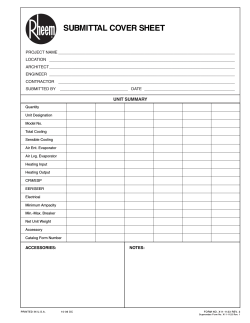
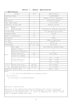


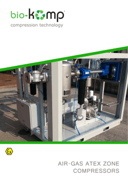
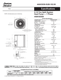

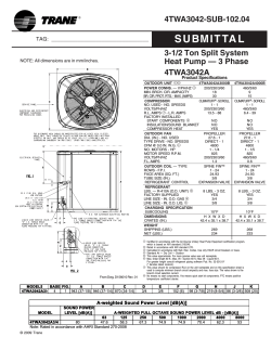
© Copyright 2026