
KinectFusion: Real-time 3D Reconstruction and Interaction Using a Moving Depth Camera*
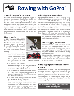
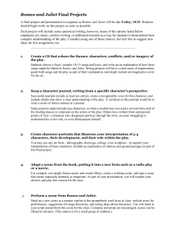
KinectFusion: Real-time 3D Reconstruction and Interaction
Using a Moving Depth Camera*
Shahram Izadi1 , David Kim1,3 , Otmar Hilliges1 , David Molyneaux1,4 , Richard Newcombe2 ,
Pushmeet Kohli1 , Jamie Shotton1 , Steve Hodges1 , Dustin Freeman1,5 ,
Andrew Davison2 , Andrew Fitzgibbon1
2
Microsoft Research Cambridge, UK
Imperial College London, UK
3
4
5
Newcastle University, UK
Lancaster University, UK
University of Toronto, Canada
1
Figure 1: KinectFusion enables real-time detailed 3D reconstructions of indoor scenes using only the depth data from a
standard Kinect camera. A) user points Kinect at coffee table scene. B) Phong shaded reconstructed 3D model (the wireframe
frustum shows current tracked 3D pose of Kinect). C) 3D model texture mapped using Kinect RGB data with real-time particles
simulated on the 3D model as reconstruction occurs. D) Multi-touch interactions performed on any reconstructed surface. E)
Real-time segmentation and 3D tracking of a physical object.
ABSTRACT
KinectFusion enables a user holding and moving a standard
Kinect camera to rapidly create detailed 3D reconstructions
of an indoor scene. Only the depth data from Kinect is used
to track the 3D pose of the sensor and reconstruct, geometrically precise, 3D models of the physical scene in real-time.
The capabilities of KinectFusion, as well as the novel GPUbased pipeline are described in full. We show uses of the core
system for low-cost handheld scanning, and geometry-aware
augmented reality and physics-based interactions. Novel extensions to the core GPU pipeline demonstrate object segmentation and user interaction directly in front of the sensor,
without degrading camera tracking or reconstruction. These
extensions are used to enable real-time multi-touch interactions anywhere, allowing any planar or non-planar reconstructed physical surface to be appropriated for touch.
H5.2 [Information Interfaces and Presentation]: User Interfaces. I4.5 [Image Processing and Computer Vision]: Reconstruction. I3.7 [Computer Graphics]:
Three-Dimensional Graphics and Realism.
ACM Classification:
General terms:
Algorithms, Design, Human Factors.
3D, GPU, Surface Reconstruction, Tracking,
Depth Cameras, AR, Physics, Geometry-Aware Interactions
Keywords:
* Research conducted at Microsoft Research Cambridge, UK
Permission to make digital or hard copies of all or part of this work for
personal or classroom use is granted without fee provided that copies are
not made or distributed for profit or commercial advantage and that copies
bear this notice and the full citation on the first page. To copy otherwise, to
republish, to post on servers or to redistribute to lists, requires prior specific
permission and/or a fee.
UIST’11, October 16-19, 2011, Santa Barbara, CA, USA.
Copyright 2011 ACM 978-1-4503-0716-1/11/10...$10.00.
INTRODUCTION
While depth cameras are not conceptually new, Kinect has
made such sensors accessible to all. The quality of the depth
sensing, given the low-cost and real-time nature of the device, is compelling, and has made the sensor instantly popular with researchers and enthusiasts alike.
The Kinect camera uses a structured light technique [8] to
generate real-time depth maps containing discrete range measurements of the physical scene. This data can be reprojected as a set of discrete 3D points (or point cloud). Even
though the Kinect depth data is compelling, particularly compared to other commercially available depth cameras, it is
still inherently noisy (see Figures 2B and 3 left). Depth measurements often fluctuate and depth maps contain numerous
‘holes’ where no readings were obtained.
To generate 3D models for use in applications such as gaming, physics, or CAD, higher-level surface geometry needs
to be inferred from this noisy point-based data. One simple
approach makes strong assumptions about the connectivity
of neighboring points within the Kinect depth map to generate a mesh representation. This, however, leads to noisy
and low-quality meshes as shown in Figure 2C. As importantly, this approach creates an incomplete mesh, from only
a single, fixed viewpoint. To create a complete (or even watertight) 3D model, different viewpoints of the physical scene
must be captured and fused into a single representation.
This paper presents a novel interactive reconstruction system called KinectFusion (see Figure 1). The system takes
live depth data from a moving Kinect camera and, in realtime, creates a single high-quality, geometrically accurate,
3D model. A user holding a standard Kinect camera can
move within any indoor space, and reconstruct a 3D model
of the physical scene within seconds. The system contin-
Figure 2: RGB image of scene (A). Extracted normals (B) and surface reconstruction (C) from a single bilateral filtered Kinect
depth map. 3D model generated from KinectFusion showing surface normals (D) and rendered with Phong shading (E).
uously tracks the 6 degrees-of-freedom (DOF) pose of the
camera and fuses new viewpoints of the scene into a global
surface-based representation. A novel GPU pipeline allows
for accurate camera tracking and surface reconstruction at interactive real-time rates. This paper details the capabilities of
our novel system, as well as the implementation of the GPU
pipeline in full.
We demonstrate core uses of KinectFusion as a low-cost
handheld scanner, and present novel interactive methods for
segmenting physical objects of interest from the reconstructed
scene. We show how a real-time 3D model can be leveraged
for geometry-aware augmented reality (AR) and physicsbased interactions, where virtual worlds more realistically
merge and interact with the real.
Placing such systems into an interaction context, where users
need to dynamically interact in front of the sensor, reveals a
fundamental challenge – no longer can we assume a static
scene for camera tracking or reconstruction. We illustrate
failure cases caused by a user moving in front of the sensor.
We describe new methods to overcome these limitations, allowing camera tracking and reconstruction of a static background scene, while simultaneously segmenting, reconstructing and tracking foreground objects, including the user. We
use this approach to demonstrate real-time multi-touch interactions anywhere, allowing a user to appropriate any physical
surface, be it planar or non-planar, for touch.
RELATED WORK
Reconstructing geometry using active sensors [16], passive
cameras [11, 18], online images [7], or from unordered 3D
points [14, 29] are well-studied areas of research in computer graphics and vision. There is also extensive literature
within the AR and robotics community on Simultaneous Localization and Mapping (SLAM), aimed at tracking a user or
robot while creating a map of the surrounding physical environment (see [25]). Given this broad topic, and our desire
to build a system for interaction, this section is structured
around specific design goals that differentiate KinectFusion
from prior work. The combination of these features makes
our interactive reconstruction system unique.
Our primary goal with KinectFusion is to
achieve real-time interactive rates for both camera tracking
and 3D reconstruction. This speed is critical for permitting
direct feedback and user interaction. This differentiates us
from many existing reconstruction systems that support only
offline reconstructions [7], real-time but non-interactive rates
(e.g. the Kinect-based system of [12] reconstructs at ∼2Hz),
Interactive rates
or support real-time camera tracking but non real-time reconstruction or mapping phases [15, 19, 20].
No explicit feature detection Unlike structure from motion (SfM) systems (e.g. [15]) or RGB plus depth (RGBD)
techniques (e.g. [12, 13]), which need to robustly and continuously detect sparse scene features, our approach to camera tracking avoids an explicit detection step, and directly
works on the full depth maps acquired from the Kinect sensor. Our system also avoids the reliance on RGB (used in
recent Kinect RGBD systems e.g. [12]) allowing use in indoor spaces with variable lighting conditions.
High-quality reconstruction of geometry A core goal of
our work is to capture detailed (or dense) 3D models of
the real scene. Many SLAM systems (e.g. [15]) focus
on real-time tracking, using sparse maps for localization
rather than reconstruction. Others have used simple pointbased representations (such as surfels [12] or aligned pointclouds [13]) for reconstruction. KinectFusion goes beyond
these point-based representations by reconstructing surfaces,
which more accurately approximate real-world geometry.
Dynamic interaction assumed We explore tracking and
reconstruction in the context of user interaction. Given this
requirement, it is critical that the representation we use can
deal with dynamically changing scenes, where users directly
interact in front of the camera. While there has been work
on using mesh-based representations for live reconstruction
from passive RGB [18, 19, 20] or active Time-of-Flight (ToF)
cameras [4, 28], these do not readily deal with changing, dynamic scenes.
Infrastructure-less We aim to allow users to explore and
reconstruct arbitrary indoor spaces. This suggests a level of
mobility, and contrasts with systems that use fixed or large
sensors (e.g. [16, 23]) or are fully embedded in the environment (e.g. [26]). We also aim to perform camera tracking without the need for prior augmentation of the space,
whether this is the use of infrastructure-heavy tracking systems (e.g. [2]) or fiducial markers (e.g. [27]).
Room scale One final requirement is to support whole
room reconstructions and interaction. This differentiates
KinectFusion from prior dense reconstruction systems, which
have either focused on smaller desktop scenes [19, 20] or
scanning of small physical objects [4, 28].
The remainder of this paper is structured into two parts: The
first provides a high-level description of the capabilities of
KinectFusion. The second describes the technical aspects of
the system, focusing on our novel GPU pipeline.
Figure 3: Left: Raw Kinect data (shown as surface normals). Right: Reconstruction shows hole filling and highquality details such as keys on keyboard, phone number
pad, wires, and even a DELL logo on the side of a PC (an
engraving less than 1mm deep).
Figure 4: A) User rotating object in front of fixed Kinect.
B) 360◦ 3D reconstruction. C) 3D model imported into
SolidWorks. D) 3D printout from reconstruction.
KINECTFUSION
Our system allows a user to pickup a standard Kinect camera
and move rapidly within a room to reconstruct a high-quality,
geometrically precise 3D model of the scene. To achieve this,
our system continually tracks the 6DOF pose of the camera
and fuses live depth data from the camera into a single global
3D model in real-time. As the user explores the space, new
views of the physical scene are revealed and these are fused
into the same model. The reconstruction therefore grows in
detail as new depth measurements are added. Holes are filled,
and the model becomes more complete and refined over time
(see Figure 3).
Even small motions, caused for example by camera shake,
result in new viewpoints of the scene and hence refinements
to the model. This creates an effect similar to image superresolution [6] – adding greater detail than appears visible in
the raw signal (see Figure 3). As illustrated in Figures 2
and 3, the reconstructions are high-quality, particularly given
the noisy input data and speed of reconstruction. The reconstructed model can also be texture mapped using the Kinect
RGB camera (see Figures 1C, 5B and 6A).
A basic and yet compelling
use for KinectFusion is as a low-cost object scanner. Although there is a body of research focusing on object scanning using passive and active cameras [4, 28], the speed,
quality, and scale of reconstructions have not been demonstrated previously with such low-cost commodity hardware.
The mobile and real-time nature of our system allows users
to rapidly capture an object from different viewpoints, and
Low-cost Handheld Scanning
Figure 5: Fast and direct object segmentation. First entire
scene is scanned including object of interest – the teapot.
3D reconstruction shows surface normals (A) and texture
mapped model (B). Bottom left to right: Teapot physically
removed. System monitors real-time changes in reconstruction and colors large changes yellow. C) This achieves
accurate segmentation of teapot 3D model from initial scan.
see onscreen feedback immediately. Reconstructed 3D models can be imported into CAD or other 3D modeling applications, or even 3D printed (see Figure 4 C and D).
As also shown in Figure 4, our system can also be used in
‘reverse’ – without any code changes – whereby the system
tracks the 6DOF pose of a handheld rigid object that is rotated in front of a fixed Kinect camera (as long as the object
occupies the majority of the depth map). While fingers and
hands may initially form part of the 3D reconstruction, they
are gradually integrated out of the 3D model, because they
naturally move as a process of rotating the object.
Object Segmentation through Direct Interaction Users
may also wish to scan a specific smaller physical object
rather than the entire scene. To support this, KinectFusion
allows a user to first reconstruct the entire scene, and then
accurately segment the desired object by moving it physically. The system continuously monitors the 3D reconstruction and observes changes over time. If an object is physically removed from view or moved within the scene by the
user, rapid and large changes in the 3D model are observed.
Such changes are detected in real-time, allowing the repositioned object to be cleanly segmented from the background
model. This approach allows a user to perform segmentation rapidly and without any explicit GUI input, simply by
moving the object directly (see Figure 5).
Geometry-Aware Augmented Reality Beyond scanning,
KinectFusion enables more realistic forms of AR, where a
3D virtual world is overlaid onto and interacts with the realworld representation. Figure 6 (top row) shows a virtual
metallic sphere composited directly onto the 3D model, as
well as the registered live RGB data from Kinect. The virtual sphere can be rendered from the same perspective as
the tracked physical camera, enabling it to be spatially registered as the Kinect moves. As shown in Figure 6 (B, C and
D), the live 3D model allows composited virtual graphics to
be precisely occluded by the real-world, including geometrically complex objects. This quality of occlusion handling is
not possible with the raw depth map (Figure 6E), especially
around the edges of objects due to significant noise along
depth discontinuities. Precise occlusions are critical for truly
immersive AR experiences, and have not been achieved in
sparsely mapped real-time AR systems (e.g. [15]).
Figure 6: Virtual sphere composited onto texture mapped
3D model (A) and calibrated live Kinect RGB (B, C and D).
Real-time 3D model used to handle precise occlusions of
the virtual by complex physical geometries (B and C). Comparing occlusion handling using live depth map (E) versus
3D reconstruction (F). Note noise at depth edges, shadows
and incomplete data (e.g. book) in live depth map. Virtual
sphere casts shadows on physical (D) and reflects parts of
the real scene (B and D).
Figure 8: A user moves freely in front of a fixed Kinect. Live
raw data (top) and shaded reconstruction (bottom). Left:
Scene without user. Middle: User enters scene, but is only
partially reconstructed due to motion. Right: Continued
scene motions cause tracking failure.
construct a scene and simultaneously perform physics computations on the model is unique, and opens up a potential
for more physically realistic AR applications.
Reaching into the Scene
It is important to note that, like most of the related literature
on SLAM and camera-based reconstruction, our core system described so far makes a fundamental assumption – that
camera tracking will be performed on a static scene. Once
we switch focus from reconstructing the scene towards interacting within it, these assumptions no longer hold true.
Physical objects such as the user’s hands, will inevitably appear in the scene, move dynamically and impact tracking and
reconstruction. Our camera tracking is robust to transient and
rapid scene motions (such as the earlier example in Figure 5).
However, prolonged interactions with the scene are problematic as illustrated in Figure 8.
Figure 7: Interactive simulation of physics directly on 3D
model even during reconstruction. Thousands of particles
interact with reconstructed scene. Reconstruction, camera
tracking, and physics simulation all performed in real-time.
Raytraced rendering effects can be calculated in real-time to
create realistic shadows, lighting and reflections that consider
both virtual and real geometries. For example, Figure 6 (B
and D) shows how the virtual can cast shadows onto the real
geometry, as well as reflect parts of the real scene onto the
virtual. The latter can even be parts of the scene that are
occluded from the current perspective of the physical camera.
Taking this ability
of combining and spatially aligning real and virtual worlds
one step further, the virtual can also begin to interact dynamically with the reconstructed scene by simulating aspects
of real-world physics. Many types of applications such as
gaming and robotics can benefit from such physically precise
real-time simulation. Rigid body collisions can be simulated
live even as the 3D model is being reconstructed. Figure 7
shows thousands of particles interacting with the 3D model
as it is reconstructed, all in real-time. This ability to both reTaking Physics Beyond the ‘Surface’
While this is clearly a challenging problem within computer
vision, our GPU-based pipeline is extended to approximate
camera motion from scene motion for certain user interaction scenarios. When a user is interacting in the scene, the
camera tracking ‘locks’ onto the background and ignores the
foreground user for camera pose prediction (shown later in
Figure 15). This foreground data can be tracked (in 6DOF)
and reconstructed independently of camera tracking and reconstruction of the static background.
This ability to reconstruct and track the user in the scene
can enable novel extensions to our physics-based simulation shown earlier. Rigid particles can now collide with
the rapidly changing dynamic foreground. Figure 9 demonstrates particles interacting with a dynamically updated reconstruction of a moving user. This enables direct interaction
between the user and the physics-enabled virtual objects.
Furthermore, as we have captured geometry of both the background scene and foreground user (e.g. hands or potentially
the full body), we can determine intersections between the
two. These points of intersection indicate when the foreground ‘comes into contact with’ the background, and forms
a robust method to detect when a user is touching any arbitrarily shaped surface – including non-planar geometries.
This allows direct multi-touch interactions, such as those
Figure 9: Interactive simulation of particle physics on dynamic scenes. Particles interact with dynamically moving
foreground user, whilst physical camera and user move.
User can collide with the physics-enabled virtual objects.
Figure 11: Overview of tracking and reconstruction pipeline
from raw depth map to rendered view of 3D scene.
volume also equates to a synthetic depth map, which can
be used as a less noisy more globally consistent reference
frame for the next iteration of ICP. This allows tracking by
aligning the current live depth map with our less noisy raycasted view of the model, as opposed to using only the live
depth maps frame-to-frame.
Each of these steps is executed in parallel on the GPU using
the CUDA language. We describe each of these steps of the
pipeline in the following sections.
Figure 10: Enabling touch input on arbitrary surfaces with
a moving camera. A) Live RGB. B) Composited view with
segmented hand and single finger touching curved surface.
C) rendered as surface normals. D) Single finger drawing
on a curved surface. E) Multi-touch on regular planar book
surface. F) Multi-touch on an arbitrarily shaped surface.
demonstrated in the interactive tabletop community, to reach
any surface in the user’s environment (see Figure 10).
GPU IMPLEMENTATION
Our approach for real-time camera tracking and surface reconstruction is based on two well-studied algorithms [1, 5,
24], which have been designed from the ground-up for parallel execution on the GPU. A full formulation of our method is
provided in [21], as well as quantitative evaluation of reconstruction performance. The focus of this section is on the implementation of our novel core and extended GPU pipeline,
which is critical in enabling interactive rates.
The main system pipeline consists of four main stages (labeled appropriately in Figure 11):
a) Depth Map Conversion The live depth map is converted
from image coordinates into 3D points (referred to as vertices) and normals in the coordinate space of the camera.
b) Camera Tracking In the tracking phase, a rigid 6DOF
transform is computed to closely align the current oriented
points with the previous frame, using a GPU implementation of the Iterative Closest Point (ICP) algorithm [1]. Relative transforms are incrementally applied to a single transform that defines the global pose of the Kinect.
c) Volumetric Integration Instead of fusing point clouds or
creating a mesh, we use a volumetric surface representation
based on [5]. Given the global pose of the camera, oriented
points are converted into global coordinates, and a single 3D
voxel grid is updated. Each voxel stores a running average
of its distance to the assumed position of a physical surface.
d) Raycasting Finally, the volume is raycast to extract views
of the implicit surface, for rendering to the user. When using the global pose of the camera, this raycasted view of the
Depth Map Conversion
At time i, each CUDA thread operates in parallel on a separate pixel u = (x, y) in the incoming depth map Di (u).
Given the intrinsic calibration matrix K (of the Kinect infrared camera), each GPU thread reprojects a specific depth
measurement as a 3D vertex in the camera’s coordinate space
as follows: vi (u) = Di (u) K−1 [u, 1]. This results in a single vertex map Vi computed in parallel.
Corresponding normal vectors for each vertex are computed
by each GPU thread using neighboring reprojected points:
ni (u) = (vi (x+1, y)−vi (x, y))×(vi (x, y +1)−vi (x, y))
(normalized to unit length ni /||ni ||). This results in a single
normal map Ni computed in parallel.
The 6DOF camera pose at time i is a rigid body transform
matrix Ti = [Ri |ti ] containing a 3x3 rotation matrix (Ri )
and 3D translation vector (ti ). Given this transform, a vertex and normal can be converted into global coordinates:
vig (u) = Ti vi (u) and ngi (u) = Ri ni (u) respectively.
Camera Tracking
ICP is a popular and well-studied algorithm for 3D shape
alignment (see [24] for a detailed study). In KinectFusion,
ICP is instead leveraged to track the camera pose for each
new depth frame, by estimating a single 6DOF transform
that closely aligns the current oriented points with those of
the previous frame. This gives a relative 6DOF transform
which can be incrementally applied together to give the single global camera pose Ti .
The important first step of ICP is to find correspondences between the current oriented points at time i with the previous
at i−1. In our system we use projective data association [24]
to find these correspondences. This part of the GPU-based algorithm is shown as pseudocode in Listing 1. Given the previous global camera pose Ti−1 , each GPU thread transforms
a unique point vi−1 into camera coordinate space, and perspective projects it into image coordinates. It then uses this
2D point as a lookup into the current vertex (Vi ) and normal
maps (Ni ), finding corresponding points along the ray (i.e.
projected onto the same image coordinates). Finally, each
GPU thread tests the compatibility of corresponding points
to reject outliers, by first converting both into global coordinates, and then testing that the Euclidean distance and angle
between them are within a threshold. Note that Ti is initialized with Ti−1 and is updated with an incremental transform
calculated per iteration of ICP.
Listing 1 Projective point-plane data association.
1: for each image pixel u ∈ depth map Di in parallel do
2:
if Di (u) > 0 then
g
3:
vi−1 ← T−1
i−1 vi−1
4:
p ← perspective project vertex vi−1
5:
if p ∈ vertex map Vi then
6:
v ← Ti Vi (p)
7:
n ← Ri Ni (p)
8:
if ||v − vgi−1 || < distance threshold and
abs(n · ngi−1 ) < normal threshold then
9:
point correspondence found
Given these set of corresponding oriented points, the output
of each ICP iteration is a single transformation matrix T that
minimizes the point-to-plane error metric [3], defined as the
sum of squared distances between each point in the current
frame and the tangent plane at its corresponding point in the
previous frame:
�
g
arg min
||(Tvi (u) − vi−1
(u)) · ngi−1 (u)||2 (1)
u
Di (u)>0
We make a linear approximation to solve this system, by assuming only an incremental transformation occurs between
frames [3, 17]. The linear system is computed and summed
in parallel on the GPU using a tree reduction. The solution
to this 6x6 linear system is then solved on the CPU using a
Cholesky decomposition.
One of the key novel contributions of our GPU-based camera tracking implementation is that ICP is performed on all
the measurements provided in each 640×480 Kinect depth
map. There is no sparse sampling of points or need to explicitly extract features (although of course ICP does implicitly
require depth features to converge). This type of dense tracking is only feasible due to our novel GPU implementation,
and plays a central role in enabling segmentation and user
interaction in KinectFusion, as described later.
Volumetric Representation
By predicting the global pose of the camera using ICP, any
depth measurement can be converted from image coordinates
into a single consistent global coordinate space. We integrate
this data using a volumetric representation based on [5]. A
3D volume of fixed resolution is predefined, which maps to
specific dimensions of a 3D physical space. This volume is
subdivided uniformly into a 3D grid of voxels. Global 3D
vertices are integrated into voxels using a variant of Signed
Distance Functions (SDFs) [22], specifying a relative distance to the actual surface. These values are positive in-front
of the surface, negative behind, with the surface interface defined by the zero-crossing where the values change sign.
In practice, we only store a truncated region around the actual
surface [5] – referred to in this paper as Truncated Signed
Distance Functions (TSDFs). We have found this representation has many advantages for the Kinect sensor data,
particularly when compared to other representations such as
meshes. It implicitly encodes uncertainty in the range data,
efficiently deals with multiple measurements, fills holes as
new measurements are added, accommodates sensor motion,
and implicitly stores surface geometry.
Listing 2 Projective TSDF integration leveraging coalesced
memory access.
1: for each voxel g in x,y volume slice in parallel do
2:
while sweeping from front slice to back do
3:
vg ← convert g from grid to global 3D position
g
4:
v ← T−1
i v
5:
p ← perspective project vertex v
6:
if v in camera view frustum then
7:
sdf i ← ||ti −vg || − Di (p)
8:
if (sdf i > 0) then
9:
tsdf i ← min(1, sdf i / max truncation)
10:
else
11:
tsdf i ← max(−1, sdf i / min truncation)
12:
wi ←min(max weight, wi−1 + 1)
i−1 +tsdf i wi
13:
tsdf avg ← tsdf i−1wwi−1
+wi
14:
store wi and tsdf avg at voxel g
To achieve real-time rates, we describe a novel GPU implementation of volumetric TSDFs.
The full 3D voxel grid is allocated on the GPU as aligned
linear memory. Whilst clearly not memory efficient (a 5123
volume containing 32-bit voxels requires 512MB of memory), our approach is speed efficient. Given the memory is
aligned, access from parallel threads can be coalesced to increase memory throughput.
Volumetric Integration
The algorithm ensures coalesced access to the voxel grid,
whilst integrating depth data projectively. The algorithm
updates TSDF values in the volume at real-time rates (as
quickly as 2ms for a 5123 volume), and allows continuous
surface estimates to be discretized into the voxel grid, from
the point-based Kinect depth maps. Furthermore, this approach is much simpler to implement than hierarchical techniques (e.g. [29]), but with the increased available memory
on commodity GPUs, can scale to modeling a whole room.
The pseudocode Listing 2 illustrates the main steps of our algorithm. Due to the large number of voxels typically within
a volume, it is not feasible to launch a GPU thread per voxel.
To ensure coalesced memory access, a GPU thread is assigned to each (x, y) position on the front slice of the volume. In parallel, GPU threads then sweep through the volume, moving along each slice on the Z-axis. Given the resolution of the volume, and the physical dimensions this maps
to, each discrete 3D grid location can be converted into a vertex in global coordinates. A metric distance from the camera
center (the translation vector of the global camera transform)
to this vertex can be calculated. This 3D vertex can also be
perspective projected back into image coordinates to lookup
the actual depth measurement along the ray. The difference
between measured and calculated distances gives a new SDF
value for the voxel (line 7). This is normalized to a TSDF
(lines 9 and 11) and averaged with the previous stored value
using a simple running weighted average (line 13) [5]. Both
the new weight and averaged TSDF are stored at the voxel.
Raycasting for Rendering and Tracking A GPU-based
raycaster is implemented to generate views of the implicit
surface within the volume for rendering and tracking (see
pseudocode Listing 3). In parallel, each GPU thread walks
a single ray and renders a single pixel in the output image.
Given a starting position and direction of the ray, each GPU
thread traverses voxels along the ray, and extracts the position of the implicit surface by observing a zero-crossing (a
change in the sign of TSDF values stored along the ray). The
final surface intersection point is computed using a simple
linear interpolation given the trilinearly sampled points either
side of the zero-crossing. Assuming the gradient is orthogonal to the surface interface, the surface normal is computed
directly as the derivative of the TSDF at the zero-crossing
[22]. Therefore each GPU thread that finds a ray/surface intersection can calculate a single interpolated vertex and normal, which can used as parameters for lighting calculations
on the output pixel, in order to render the surface.
Listing 3 Raycasting to extract the implicit surface, composite virtual 3D graphics, and perform lighting operations.
1: for each pixel u ∈ output image in parallel do
2:
raystart ← back project [u, 0]; convert to grid pos
3:
raynext ← back project [u, 1]; convert to grid pos
4:
raydir ← normalize (raynext − raystart )
5:
raylen ← 0
6:
g ← first voxel along raydir
7:
m ← convert global mesh vertex to grid pos
8:
mdist ← ||raystart − m||
9:
while voxel g within volume bounds do
10:
raylen ← raylen + 1
11:
gprev ← g
12:
g ← traverse next voxel along raydir
13:
if zero crossing from g to gprev then
14:
p ← extract trilinear interpolated grid position
15:
v ← convert p from grid to global 3D position
16:
n ← extract surface gradient as ∇tsdf (p)
17:
shade pixel for oriented point (v, n) or
18:
follow secondary ray (shadows, reflections, etc)
19:
if raylen > mdist then
20:
shade pixel using inputed mesh maps or
21:
follow secondary ray (shadows, reflections, etc)
Our rendering pipeline shown in Figure 12 also allows conventional polygon-based graphics to be composited on the
raycasted view, enabling blending of virtual and real scenes
with correct occlusion handling (see Figure 6). In the first
step (labeled a), a mesh-based scene is rendered with graphics camera parameters identical to the physical global camera pose (Ti ) and intrinsics (K). Instead of rendering to the
framebuffer, the vertex buffer, surface normals and unshaded
color data are stored in off-screen vertex, normal and color
maps respectively (labeled b), and used as input during raycasting (labeled c). For each GPU thread, a distance from the
associated mesh vertex to the camera center is calculated in
grid coordinates (Listing 3 lines 7 and 8). This distance acts
as an additional termination condition while stepping along
each ray (line 19), allowing accurate occlusion testing between volumetric and mesh surface geometries.
Figure 12: Rendering pipeline combining raycasting of volume with compositing of virtual polygon-based graphics.
Ambient, diffuse and specular lighting contributions can be
calculated across reconstructed and virtual geometries (see
Figure 6). More advanced shading calculations can be performed by walking along the second (and possibly further)
bounce of each ray. Shadows are calculated after the first ray
hits a voxel or mesh surface (Listing 3 line 13 and 19), by
walking a secondary ray from the surface to light position
(using grid coordinates). If a surface is hit before ray termination then the vertex is shadowed. For reflections, once
the first ray hits a surface, a new ray direction is calculated,
based on the surface normal and initial ray direction.
A novel contribution of our raycaster is the ability to view
the implicit surface of the reconstructed 3D model, composite polygon geometry with correct occlusion handling, and
provide advanced shading requiring raytraced operations, all
in real-time, through a single algorithm. Any 6DOF graphics camera transform can be used to raycast the volume, including arbitrary third-person views allowing user navigation
of the 3D model. However, another key contribution of our
raycaster, is in generating higher-quality data for ICP camera tracking. When the raycast camera transform equates to
the physical camera pose, the extracted vertices and normals
equate to depth and normal maps (from the same perspective as the physical camera) but with considerably less noise,
shadows and holes than the raw Kinect data. As shown in
[21], this allows us to mitigate issues of drift and reduce ICP
errors, by tracking directly from the raycasted model as opposed to frame-to-frame ICP tracking.
Simulating Real-World Physics
Taking the merging of real and virtual geometries further,
the GPU pipeline is extended to support simulation of physically realistic collisions between virtual objects and the reconstructed scene. A particle simulation is implemented on
the GPU, based on [9] and [10]. Scene geometry is represented within the simulation by a set of static particles (see
Figure 13). These are spheres of identical size, which remain
stationary but can collide with other dynamically simulated
particles. Whilst an approximation, this technique models
every discrete surface voxel within the volume in real-time,
achieving compelling results even for very small and arbitrarily shaped objects such as a book’s edges or a teapot’s
handle in Figures 7 (bottom right) and 13.
Static particles are created during volume integration. As
the volume is swept, TSDF values within an adaptive threshold close to zero (defining the surface interface or zero level
Figure 13: Simulating physics on the real-time reconstruction. Left: Surface is approximated as series of static particles (updated per integration sweep) which interact with
dynamic particles. Every surface voxel is represented by
a static particle. Middle: Surface normals of static and dynamic particles. Right: Shaded scene with only dynamic
particles composited.
set) are extracted. For each surface voxel, a static particle
is instantiated. Each particle contains a 3D vertex in global
(metric) space, a velocity vector (always empty for static particles), and an ID. One key challenge then becomes detecting collisions. We use a spatially subdivided uniform grid to
identify neighboring particles [9]. Each cell in the grid has
a unique ID. Each dynamic or static particle is assigned a
grid cell ID by converting the particle’s global vertex to grid
coordinates. Our system then maintains two lists – one containing static particles; the other dynamic. In both, particles
are binned into the grid cells by sorting them by their current
grid ID (using a GPU-based radix sort). During each simulation step, a GPU thread is launched per dynamic particle.
Each thread processes collisions by examining (33 ) neighborhood of cells (first for dynamic-dynamic collisions and then
dynamic-static). The Discrete Element Method (DEM) [10]
is used to calculate a velocity vector when two particles collide. The particle’s global velocity is incremented based on
all neighboring collisions, gravity, and interactions with the
bounding volume. Each particle is then repositioned based
on the accumulated velocity per simulation step.
Figure 7 shows thousands of particles interacting with the reconstructed scene. A major contribution of our GPU-based
pipeline is that it maintains interactive rates despite the overhead of physics simulation, whilst performing real-time camera tracking and reconstruction. By default, only dynamic
particles are rendered during raycasting and again can be correctly occluded by the reconstructed geometry (see Figure 7).
INTERACTING IN THE SCENE
The core system described so far makes assumptions that the
scene will remain reasonably static. Clearly in an interaction
context, users want to move freely in front of the sensor, and
interact in the scene. This opens up two main challenges.
First, ICP tracking assumes a single rigid transform occurred
per frame due to camera motion. User interaction in front
of the sensor will cause scene motion independent of camera motion, which breaks this assumption. Because our ICP
tracking is dense (i.e. uses all available points) our system is
resilient to transient scene motions. For example, in Figure 5,
even when the user moves the object, enough background
points will remain for ICP to converge. However, large or
longer-term scene motions will cause tracking failure.
Second, whilst our system supports real-time reconstruction,
surface predictions are refined over time using a running
weighted average of distance values. By adapting the weighting, higher precedence can be given to new TSDF values,
allowing for faster model updates, but the trade-off is addi-
Figure 14: Extended GPU pipeline for real-time foreground
and background segmentation, tracking and reconstruction.
tional noise being introduced to the reconstruction. In practice, a weight is chosen to balance quality of reconstruction
with regular updates to the reconstruction based on scene
changes. However, this does not support a continuously moving scene. Typically a user freely moving in the scene leads
to associated depth data being partially integrated into the
volume (Figure 8 middle). As camera tracking relies directly
on this model, which is now inconsistent with the live data,
failures will occur (Figure 8 right).
To begin to explore dynamic user interaction with the reconstructed scene, a novel
extension to the core GPU pipeline is provided (shown in
Figure 14). The technique leverages a unique property of
dense ICP tracking. When all depth measurements are used,
outliers from projective data association can form a strong
initial predication as to parts of the scene moving independent of camera motion – if enough rigid background points
are present for ICP still to converge. Our solution robustly
segments a moving foreground object from the background,
allowing tracking failures to be reduced, and enabling users
to interact directly in the scene.
This pipeline assumes that at least parts of a rigid scene
have been initially reconstructed using the core reconstruction pipeline (labeled a). After this initial scan, a moving
object entering the scene contains oriented points with significant disparity to already reconstructed surfaces. These fail
ICP projective data association and are copied into an outlier map (labeled b). Next, a depth-aware connected component analysis is performed on the outlier map to cluster large
connected patches and remove smaller outliers due to sensor noise (labeled c). Large connected patches, where foreground scene motion has been detected, are masked in the input depth map for core ‘background’ reconstruction (labeled
d). This stops associated foreground depth measurements being used for reconstruction or tracking in the core pipeline.
Large patches of outliers can be additionally reconstructed
using a second volume (labeled e) – potentially running on a
separate GPU with different reconstruction settings. A final
step raycasts the two separate volumes and composites the
output (labeled f), using the same method as Figure 12.
ICP Outliers for Segmentation
Figure 15: Moving user is segmented and reconstructed,
independent of background. Left to right: 1) Live RGB.
2) ICP outliers (for initial segmentation prediction). 3) final
composited scene showing foreground shaded differently to
background. 4) Composited normal maps.
Overall our technique yields compelling results in stabilizing tracking and therefore improving reconstruction quality
for a static background, even when parts of the scene continually move in front of the camera. Furthermore, it allows a
foreground object to be robustly segmented, and potentially
reconstructed separately of the background (see Figure 15).
Listing 4 Create touch map – testing if foreground and background vertices overlap.
g
1: Vfg ← raycasted vertex map from foreground volume
2: for each pixel u ∈ O (touch map) in parallel do
3:
cast single ray for u (as Listing 3)
4:
if zero crossing when walking ray then
g
5:
vbg
← interpolated global zero crossing position
g
g
6:
if ||vbg
− Vfg
(u)|| < adaptive threshold then
g
7:
O(u) ← Vfg
(u)
The pipeline can
be further extended to support multi-touch input by observing intersections between foreground and background. We
extend the default raycasting of the background volume to
output a touch map, as shown in pseudocode Listing 4. Using the raycasted foreground vertex map as input, each GPU
thread again walks a ray through the background volume. If
a zero crossing is located, the corresponding foreground vertex (along the same ray) is tested (line 6). If foreground and
background are within range, the foreground position is output in the touch map. A depth-aware connected component
analysis of the touch map suppresses noise and labels fingertip candidates, which are tracked over time. Examples of
enabling multi-touch on both planar and non-planar surfaces
are shown in Figures 10 and 16.
Detecting Touch on Arbitrary Surfaces
Towards Modeling of Dynamic Scenes
The ability of now distinguishing moving foreground robustly from background raises interesting questions regarding how best to reconstruct such moving surfaces. The key
challenge becomes how to integrate foreground data into a
second volume so that correspondence between surface measurements can be ensured over time. As an initial exploration, we have experimented with independently predicting
the pose of the foreground object using another instance of
Figure 16: Segmentation, tracking and reconstruction of
user’s arm with moving Kinect. Top left: Arm is first introduced and reconstruction contains a great deal of noise.
Top right: surface is refined based on separate ICP-based
pose prediction. Bottom left: the moving surface is rapidly
reconstructed to a much higher quality than the raw Kinect
signal. Bottom right: The intersection between foreground
and background surfaces are used for multi-touch detection.
ICP. Again dense ICP is performed but only using the foreground oriented points (from the live depth map and raycasted second volume). In practice we have found that dense
ICP converges even if small parts of the foreground are moving non-rigidly. A compelling example is a user’s arm (Figure 15) where ICP converges on the rigid parts even if fingers are moving non-rigidly. This offers a coarse method for
predicting the pose of the foreground object, relative to the
global camera transform.
Using this predicted pose, depth measurements can be aligned
and fused into the second volume. A surface prediction of
the foreground, which becomes more refined and complete,
can be built up over time. Because the foreground surface
will likely be moving, we give more weight to new measurements being integrated. One simple extension uses a pervoxel weighting, adapted based on a running average of the
derivative of the TSDF (prior to integration). This allows
us to adapt the weight of individual surface voxels, giving
higher priority to new measurements when the rate of change
is high (e.g. fingers or hands), and lower if the TSDF measurements are stable (e.g. the forearm). Figures 16 and 15
shows our initial results based on foreground ICP tracking
and per-voxel adaptive weighting. Note there is considerably
less noise than the raw Kinect data – the user’s arms, hand
and fingers are clearly identifiable – and that this foreground
reconstruction occurs alongside camera tracking and refinement of the background reconstruction.
For our physics simulation, we can now represent the entire
foreground reconstruction as static particles, allowing collisions between the moving user, and the dynamic particles,
to be modeled per frame (as shown in Figure 9). This approach of reconstructing a moving foreground, can also be
used purely to track the pose of rigid objects held in the user’s
hand – enabling tracking independent of camera motion and
without markers or prior knowledge of the object. One example is shown in Figure 1 (far right) where an already reconstructed teapot (from Figure 5) is tracked in 6DOF and
re-registered with the real physical object.
CONCLUSIONS
We have presented KinectFusion, a real-time 3D reconstruction and interaction system using a moving standard Kinect.
Our contributions are threefold. First, we detailed a novel
GPU pipeline that achieves 3D tracking, reconstruction, segmentation, rendering, and interaction, all in real-time using only a commodity camera and graphics hardware. Second, we have demonstrated core novel uses for our system:
for low-cost object scanning and advanced AR and physicsbased interactions. Third, we described new methods for segmenting, tracking and reconstructing dynamic users and the
background scene simultaneously, enabling multi-touch on
any indoor scene with arbitrary surface geometries. We believe this is the first time that a reconstruction system has
shown this level of user interaction directly in the scene.
Our hope is to scale the system further, reconstructing larger
scenes where more memory efficient representations such as
octrees might be needed [29]. Encouraged by our initial results, we also wish to explore more fine-grained methods for
tracking and reconstruction of moving deformable surfaces,
including the user. Our hope is that KinectFusion will open
many new topics for research both in terms of the underlying
technology, as well as the interactive possibilities it enables.
REFERENCES
1. P. J. Besl and N. D. McKay. A method for registration
of 3D shapes. IEEE Trans. Pattern Anal. Mach. Intell.,
14:239–256, February 1992.
12. P. Henry et al. RGB-D mapping: Using depth cameras for dense 3D modeling of indoor environments. In
Proc. of the Int. Symposium on Experimental Robotics
(ISER), 2010.
13. B. Huhle et al. Fusion of range and color images
for denoising and resolution enhancement with a nonlocal filter. Computer Vision and Image Understanding,
114(12):1336–1345, 2010.
14. M. Kazhdan, M. Bolitho, and H. Hoppe. Poisson surface reconstruction. In Proc. of the Eurographics Symposium on Geometry Processing, 2006.
15. G. Klein and D. W. Murray. Parallel tracking and mapping for small AR workspaces. In ISMAR, 2007.
16. M. Levoy et al. The digital Michelangelo project: 3D
scanning of large statues. ACM Trans. Graph., 2000.
17. K. Low. Linear least-squares optimization for point-toplane ICP surface registration. Technical report, TR04004, University of North Carolina, 2004.
18. P. Merrell et al. Real-time visibility-based fusion of
depth maps. In Proc. of the Int. Conf. on Computer
Vision (ICCV), 2007.
2. X. Cao and R. Balakrishnan. Interacting with dynamically defined information spaces using a handheld projector and a pen. In UIST, pages 225–234, 2006.
19. R. A. Newcombe and A. J. Davison. Live dense reconstruction with a single moving camera. In Proc. of the
IEEE CVPR, 2010.
3. Y. Chen and G. Medioni. Object modeling by registration of multiple range images. Image and Vision Computing (IVC), 10(3):145–155, 1992.
20. R. A. Newcombe, S. Lovegrove, and A. J. Davison.
DTAM: Dense tracking and mapping in real-time. In
Proc. of the Int. Conf. on Computer Vision (ICCV),
2011.
4. Y. Cui et al. 3D shape scanning with a time-of-flight
camera. In Computer Vision and Pattern Recognition
(CVPR), pages 1173 –1180, June 2010.
21. R. A. Newcombe et al. KinectFusion: Real-time dense
surface mapping and tracking. In ISMAR, 2011.
5. B. Curless and M. Levoy. A volumetric method for
building complex models from range images. ACM
Trans. Graph., 1996.
6. S. Farsiu et al. Fast and robust multiframe super
resolution. IEEE Transactions on Image Processing,
13(10):1327–1344, 2004.
7. J. Frahm et al. Building Rome on a cloudless day. In
Proc. Europ. Conf. on Computer Vision (ECCV), 2010.
8. B. Freedman, A. Shpunt, M. Machline, and Y. Arieli.
Depth mapping using projected patterns. Patent Application, 10 2008. WO 2008/120217 A2.
22. S. Osher and R. Fedkiw. Level set methods and dynamic
implicit surfaces. Springer, 2002.
23. S. Rusinkiewicz, O. Hall-Holt, and M. Levoy. Realtime 3D model acquisition. ACM Trans. Graph., 2002.
24. S. Rusinkiewicz and M. Levoy. Efficient variants of the
ICP algorithm. 3D Digital Imaging and Modeling, Int.
Conf. on, 0:145, 2001.
25. S. Thrun. Robotic mapping: A survey. In Exploring
Artificial Intelligence in the New Millenium. 2002.
26. D. Vlasic et al. Dynamic shape capture using multiview photometric stereo. ACM Trans. Graph., 28(5),
2009.
9. S. L. Grand. Broad-phase collision detection with
CUDA. In GPU Gems 3. Addison-Wesley, 2007.
27. D. Wagner, T. Langlotz, and D. Schmalstieg. Robust
and unobtrusive marker tracking on mobile phones. In
ISMAR, pages 121–124, 2008.
10. T. Harada. Real-time rigid body simulation on GPUs.
In GPU Gems 3. Addison-Wesley Professional, 2007.
28. T. Weise, T. Wismer, B. Leibe, and L. V. Gool. Inhand scanning with online loop closure. In IEEE Int.
Workshop on 3-D Digital Imaging and Modeling, 2009.
11. R. Hartley and A. Zisserman. Multiple view geometry in
computer vision. Cambridge University Press, second
edition, 2004.
29. K. Zhou, M. Gong, X. Huang, and B. Guo. Dataparallel octrees for surface reconstruction. IEEE Trans.
on Visualization and Computer Graphics, 17, 2011.


© Copyright 2026