
CHAPTER 10 RADIO WAVES ELECTROMAGNETIC WAVE PROPAGATION
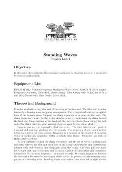
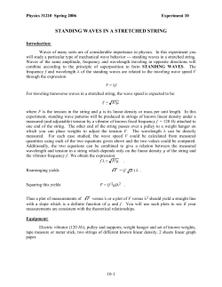
CHAPTER 10
RADIO WAVES
ELECTROMAGNETIC WAVE PROPAGATION
1000. Source of Radio Waves
Consider electric current as a flow of electrons along a
conductor between points of differing potential. A direct
current flows continuously in the same direction. This would
occur if the polarity of the electromotive force causing the
electron flow were constant, such as is the case with a battery.
If, however, the current is induced by the relative motion
between a conductor and a magnetic field, such as is the case
in a rotating machine called a generator, then the resulting
current changes direction in the conductor as the polarity of the
electromotive force changes with the rotation of the
generator’s rotor. This is known as alternating current.
The energy of the current flowing through the
conductor is either dissipated as heat (an energy loss
proportional to both the current flowing through the
conductor and the conductor’s resistance) or stored in an
electromagnetic field oriented symmetrically about the
conductor. The orientation of this field is a function of the
polarity of the source producing the current. When the
current is removed from the wire, this electromagnetic field
will, after a finite time, collapse back into the wire.
What would occur should the polarity of the current
source supplying the wire be reversed at a rate which
exceeds the finite amount of time required for the electromagnetic field to collapse back upon the wire? In this case,
another magnetic field, proportional in strength but exactly
opposite in magnetic orientation to the initial field, will be
formed upon the wire. The initial magnetic field, its current
source gone, cannot collapse back upon the wire because of
the existence of this second electromagnetic field. Instead,
it propagates out into space. This is the basic principle of a
radio antenna, which transmits a wave at a frequency
proportional to the rate of pole reversal and at a speed equal
to the speed of light.
at zero, increases to a maximum as the rotor completes one
quarter of its revolution, and falls to zero when the rotor
completes one half of its revolution. The current then
approaches a negative maximum; then it once again returns
to zero. This cycle can be represented by a sine function.
The relationship between the current and the magnetic
field strength induced in the conductor through which the
current is flowing is shown in Figure 1001. Recall from the
discussion above that this field strength is proportional to the
magnitude of the current; that is, if the current is represented
by a sine wave function, then so too will be the magnetic field
strength resulting from that current. This characteristic shape
of the field strength curve has led to the use of the term
“wave” when referring to electromagnetic propagation. The
maximum displacement of a peak from zero is called the
amplitude. The forward side of any wave is called the wave
front. For a non-directional antenna, each wave proceeds
outward as an expanding sphere (or hemisphere).
One cycle is a complete sequence of values, as from crest
to crest. The distance traveled by the energy during one cycle
is the wavelength, usually expressed in metric units (meters,
centimeters, etc.). The number of cycles repeated during unit
time (usually 1 second) is the frequency. This is given in hertz
(cycles per second). A kilohertz (kHz) is 1,000 cycles per
second. A megahertz (MHz) is 1,000,000 cycles per second.
Wavelength and frequency are inversely proportional.
The phase of a wave is the amount by which the cycle
1001. Radio Wave Terminology
The magnetic field strength in the vicinity of a
conductor is directly proportional to the magnitude of the
current flowing through the conductor. Recall the
discussion of alternating current above. A rotating
generator produces current in the form of a sine wave. That
is, the magnitude of the current varies as a function of the
relative position of the rotating conductor and the stationary
magnetic field used to induce the current. The current starts
Figure 1001. Radio wave terminology.
151
152
RADIO WAVES
has progressed from a specified origin. For most purposes it
is stated in circular measure, a complete cycle being
considered 360°. Generally, the origin is not important,
principal interest being the phase relative to that of some
other wave. Thus, two waves having crests 1/4 cycle apart
are said to be 90° “out of phase.” If the crest of one wave
occurs at the trough of another, the two are 180° out of
phase.
1002. The Electromagnetic Spectrum
The entire range of electromagnetic radiation frequencies is called the electromagnetic spectrum. The
frequency range suitable for radio transmission, the radio
spectrum, extends from 10 kilohertz to 300,000 megahertz. It is divided into a number of bands, as shown in
Table 1002.
Below the radio spectrum, but overlapping it, is the audio frequency band, extending from 20 to 20,000 hertz.
Above the radio spectrum are heat and infrared, the visible
spectrum (light in its various colors), ultraviolet, X-rays,
Band
gamma rays, and cosmic rays. These are included in Table
1002. Waves shorter than 30 centimeters are usually called
microwaves.
Within the frequencies from 1-40 gHz (1,000-40,000
MHz), additional bands are defined as follows:
L-band: 1-2 gHz (1,000-2,000 MHz)
S-band: 2-4 gHz (2,000-4,000 MHz
C-band: 4-8 gHz (4,000-8,000 MHz)
X-band: 8-12.5 gHz (8,000-12,500 MHz)
Lower K-band: 12.5-18 gHz (12,500-18,000 MHz)
Upper K-band: 26.5-40 gHz (26,500-40,000 MHz)
Marine radar systems commonly operate in the S and
X bands, while satellite navigation system signals are found
in the L-band.
The break of the K-band into lower and upper ranges is
necessary because the resonant frequency of water vapor
occurs in the middle region of this band, and severe absorption of radio waves occurs in this part of the spectrum.
Abbreviation
Range of frequency
Range of wavelength
Audio frequency
AF
20 to 20,000 Hz
15,000,000 to 15,000 m
Radio frequency
RF
10 kHz to 300,000 MHz
30,000 m to 0.1 cm
VLF
10 to 30 kHz
30,000 to 10,000 m
Low frequency
LF
30 to 300 kHz
10,000 to 1,000 m
Medium frequency
MF
300 to 3,000 kHz
1,000 to 100 m
High frequency
HF
3 to 30 MHz
100 to 10 m
Very high frequency
VHF
30 to 300 MHz
10 to 1 m
Ultra high frequency
UHF
300 to 3,000 MHz
100 to 10 cm
Super high frequency
SHF
3,000 to 30,000 MHz
10 to 1 cm
Extremely high
frequency
EHF
30,000 to 300,000 MHz
1 to 0.1 cm
Heat and infrared*
106 to 3.9×10⁸ MHz
0.03 to 7.6×10⁻⁵ cm
Visible spectrum*
3.9×10⁸ to 7.9×10⁸ MHz
7.6×10⁻⁵ to 3.8×10⁻⁵ cm
Ultraviolet*
7.9×10⁸ to 2.3×10¹⁰ MHz 3.8×10⁻⁵ to 1.3×10⁻⁶ cm
X-rays*
2.0×10⁹ to 3.0×10¹³ MHz 1.5×10⁻⁵ to 1.0×10⁻⁹ cm
Gamma rays*
2.3×10¹² to 3.0×10¹⁴ MHz 1.3×10⁻⁸ to 1.0×10⁻¹⁰ cm
Very low frequency
Cosmic rays*
>4.8×10¹⁵ MHz
* Values approximate.
Table 1002. Electromagnetic spectrum.
<6.2×10⁻¹² cm
RADIO WAVES
1003. Polarization
Radio waves produce both electric and magnetic fields.
The direction of the electric component of the field is called
the polarization of the electromagnetic field. Thus, if the
electric component is vertical, the wave is said to be
“vertically polarized,” and if horizontal, “horizontally
polarized.”
A wave traveling through space may be polarized in
any direction. One traveling along the surface of the Earth is
always vertically polarized because the Earth, a conductor,
short-circuits any horizontal component. The magnetic field
and the electric field are always mutually perpendicular.
153
frequencies, but becomes more prevalent as frequency
increases. In radio communication, it can be reduced by
using directional antennas, but this solution is not always
available for navigational systems.
Various reflecting surfaces occur in the atmosphere. At
high frequencies, reflections take place from rain. At still
higher frequencies, reflections are possible from clouds,
particularly rain clouds. Reflections may even occur at a
sharply defined boundary surface between air masses, as
when warm, moist air flows over cold, dry air. When such a
surface is roughly parallel to the surface of the Earth, radio
waves may travel for greater distances than normal The
principal source of reflection in the atmosphere is the
ionosphere.
1004. Reflection
1005. Refraction
When radio waves strike a surface, the surface reflects
them in the same manner as light waves. Radio waves of all
frequencies are reflected by the surface of the Earth. The
strength of the reflected wave depends upon angle of
incidence (the angle between the incident ray and the
horizontal), type of polarization, frequency, reflecting
properties of the surface, and divergence of the reflected
ray. Lower frequencies penetrate the earth’s surface more
than higher ones. At very low frequencies, usable radio
signals can be received some distance below the surface of
the sea.
A phase change occurs when a wave is reflected from
the surface of the Earth. The amount of the change varies
with the conductivity of the Earth and the polarization of
the wave, reaching a maximum of 180° for a horizontally
polarized wave reflected from sea water (considered to
have infinite conductivity).
When direct waves (those traveling from transmitter to
receiver in a relatively straight line, without reflection) and
reflected waves arrive at a receiver, the total signal is the
vector sum of the two. If the signals are in phase, they reinforce each other, producing a stronger signal. If there is a
phase difference, the signals tend to cancel each other, the
cancellation being complete if the phase difference is 180°
and the two signals have the same amplitude. This interaction of waves is called wave interference.
A phase difference may occur because of the change of
phase of a reflected wave, or because of the longer path it
follows. The second effect decreases with greater distance
between transmitter and receiver, for under these conditions the difference in path lengths is smaller.
At lower frequencies there is no practical solution to
interference caused in this way. For VHF and higher frequencies, the condition can be improved by elevating the
antenna, if the wave is vertically polarized. Additionally,
interference at higher frequencies can be more nearly eliminated because of the greater ease of beaming the signal to
avoid reflection.
Reflections may also occur from mountains, trees, and
other obstacles. Such reflection is negligible for lower
Refraction of radio waves is similar to that of light
waves. Thus, as a signal passes from air of one density to
that of a different density, the direction of travel is altered.
The principal cause of refraction in the atmosphere is the
difference in temperature and pressure occurring at various
heights and in different air masses.
Refraction occurs at all frequencies, but below 30 MHz
the effect is small as compared with ionospheric effects,
diffraction, and absorption. At higher frequencies,
refraction in the lower layer of the atmosphere extends the
radio horizon to a distance about 15 percent greater than the
visible horizon. The effect is the same as if the radius of the
Earth were about one-third greater than it is and there were
no refraction.
Sometimes the lower portion of the atmosphere
becomes stratified. This stratification results in nonstandard
temperature and moisture changes with height. If there is a
marked temperature inversion or a sharp decrease in water
vapor content with increased height, a horizontal radio duct
may be formed. High frequency radio waves traveling
horizontally within the duct are refracted to such an extent
that they remain within the duct, following the curvature of
the Earth for phenomenal distances. This is called superrefraction. Maximum results are obtained when both
transmitting and receiving antennas are within the duct.
There is a lower limit to the frequency affected by ducts. It
varies from about 200 MHz to more than 1,000 MHz.
At night, surface ducts may occur over land due to
cooling of the surface. At sea, surface ducts about 50 feet
thick may occur at any time in the trade wind belt. Surface
ducts 100 feet or more in thickness may extend from land
out to sea when warm air from the land flows over the
cooler ocean surface. Elevated ducts from a few feet to
more than 1,000 feet in thickness may occur at elevations of
1,000 to 5,000 feet, due to the settling of a large air mass.
This is a frequent occurrence in Southern California and
certain areas of the Pacific Ocean.
A bending in the horizontal plane occurs when a
groundwave crosses a coast at an oblique angle. This is due
154
RADIO WAVES
to a marked difference in the conducting and reflecting
properties of the land and water over which the wave travels.
The effect is known as coastal refraction or land effect.
reflection of LF and VLF waves during daylight.
1006. The Ionosphere
When a radio wave encounters a particle having an
electric charge, it causes that particle to vibrate. The
vibrating particle absorbs electromagnetic energy from the
radio wave and radiates it. The net effect is a change of
polarization and an alteration of the path of the wave. That
portion of the wave in a more highly ionized region travels
faster, causing the wave front to tilt and the wave to be
directed toward a region of less intense ionization.
Refer to Figure 1007a, in which a single layer of the
ionosphere is considered. Ray 1 enters the ionosphere at
such an angle that its path is altered, but it passes through
and proceeds outward into space. As the angle with the
horizontal decreases, a critical value is reached where ray 2
is bent or reflected back toward the Earth. As the angle is
still further decreased, such as at 3, the return to Earth
occurs at a greater distance from the transmitter.
A wave reaching a receiver by way of the ionosphere
is called a skywave. This expression is also appropriately
applied to a wave reflected from an air mass boundary. In
common usage, however, it is generally associated with the
ionosphere. The wave which travels along the surface of the
Earth is called a groundwave. At angles greater than the
critical angle, no skywave signal is received. Therefore,
there is a minimum distance from the transmitter at which
skywaves can be received. This is called the skip distance,
shown in Figure 1007a. If the groundwave extends out for
less distance than the skip distance, a skip zone occurs, in
which no signal is received.
The critical radiation angle depends upon the intensity
of ionization, and the frequency of the radio wave. As the
frequency increases, the angle becomes smaller. At frequencies greater than about 30 MHz virtually all of the
energy penetrates through or is absorbed by the ionosphere.
Therefore, at any given receiver there is a maximum usable
frequency if skywaves are to be utilized. The strongest signals are received at or slightly below this frequency. There
is also a lower practical frequency beyond which signals are
too weak to be of value. Within this band the optimum frequency can be selected to give best results. It cannot be too
near the maximum usable frequency because this frequency
fluctuates with changes of intensity within the ionosphere.
During magnetic storms the ionosphere density decreases.
The maximum usable frequency decreases, and the lower
usable frequency increases. The band of usable frequencies
is thus narrowed. Under extreme conditions it may be completely eliminated, isolating the receiver and causing a
radio blackout.
Skywave signals reaching a given receiver may arrive
by any of several paths, as shown in Figure 1007b. A signal
which undergoes a single reflection is called a “one-hop”
signal, one which undergoes two reflections with a ground
reflection between is called a “two-hop” signal, etc. A
Since an atom normally has an equal number of
negatively charged electrons and positively charged
protons, it is electrically neutral. An ion is an atom or group
of atoms which has become electrically charged, either
positively or negatively, by the loss or gain of one or more
electrons.
Loss of electrons may occur in a variety of ways. In the
atmosphere, ions are usually formed by collision of atoms
with rapidly moving particles, or by the action of cosmic
rays or ultraviolet light. In the lower portion of the
atmosphere, recombination soon occurs, leaving a small
percentage of ions. In thin atmosphere far above the surface
of the Earth, however, atoms are widely separated and a
large number of ions may be present. The region of
numerous positive and negative ions and unattached
electrons is called the ionosphere. The extent of ionization
depends upon the kinds of atoms present in the atmosphere,
the density of the atmosphere, and the position relative to
the Sun (time of day and season). After sunset, ions and
electrons recombine faster than they are separated,
decreasing the ionization of the atmosphere.
An electron can be separated from its atom only by the
application of greater energy than that holding the electron.
Since the energy of the electron depends primarily upon the
kind of an atom of which it is a part, and its position relative
to the nucleus of that atom, different kinds of radiation may
cause ionization of different substances.
In the outermost regions of the atmosphere, the density
is so low that oxygen exists largely as separate atoms, rather
than combining as molecules as it does nearer the surface of
the Earth. At great heights the energy level is low and
ionization from solar radiation is intense. This is known as
the F layer. Above this level the ionization decreases
because of the lack of atoms to be ionized. Below this level
it decreases because the ionizing agent of appropriate
energy has already been absorbed. During daylight, two
levels of maximum F ionization can be detected, the F2
layer at about 125 statute miles above the surface of the
Earth, and the F1 layer at about 90 statute miles. At night,
these combine to form a single F layer.
At a height of about 60 statute miles, the solar radiation
not absorbed by the F layer encounters, for the first time, large
numbers of oxygen molecules. A new maximum ionization
occurs, known as the E layer. The height of this layer is quite
constant, in contrast with the fluctuating F layer. At night the
E layer becomes weaker by two orders of magnitude.
Below the E layer, a weak D layer forms at a height of
about 45 statute miles, where the incoming radiation
encounters ozone for the first time. The D layer is the
principal source of absorption of HF waves, and of
1007. The Ionosphere and Radio Waves
RADIO WAVES
155
Figure 1007a. The effect of the ionosphere on radio waves.
Figure 1007b. Various paths by which a skywave signal might be received.
“multihop” signal undergoes several reflections. The layer
at which the reflection occurs is usually indicated, also, as
“one-hop E,” “two-hop F,” etc.
Because of the different paths and phase changes occurring at each reflection, the various signals arriving at a
receiver have different phase relationships. Since the density of the ionosphere is continually fluctuating, the strength
and phase relationships of the various signals may undergo
an almost continuous change. Thus, the various signals may
reinforce each other at one moment and cancel each other
at the next, resulting in fluctuations of the strength of the total signal received. This is called fading. This phenomenon
may also be caused by interaction of components within a
single reflected wave, or changes in its strength due to
changes in the reflecting surface. Ionospheric changes are
associated with fluctuations in the radiation received from
the Sun, since this is the principal cause of ionization. Signals from the F layer are particularly erratic because of the
rapidly fluctuating conditions within the layer itself.
The maximum distance at which a one-hop E signal can be
received is about 1,400 miles. At this distance the signal leaves
the transmitter in approximately a horizontal direction. A onehop F signal can be received out to about 2,500 miles. At low
frequencies groundwaves extend out for great distances.
A skywave may undergo a change of polarization
during reflection from the ionosphere, accompanied by an
alteration in the direction of travel of the wave. This is
called polarization error. Near sunrise and sunset, when
rapid changes are occurring in the ionosphere, reception
may become erratic and polarization error a maximum.
This is called night effect.
1008. Diffraction
When a radio wave encounters an obstacle, its energy is reflected or absorbed, causing a shadow beyond the obstacle.
However, some energy does enter the shadow area because of
diffraction. This is explained by Huygens’ principle, which
156
RADIO WAVES
Figure 1008. Diffraction.
states that every point on the surface of a wave front is a source
of radiation, transmitting energy in all directions ahead of the
wave. No noticeable effect of this principle is observed until the
wave front encounters an obstacle, which intercepts a portion of
the wave. From the edge of the obstacle, energy is radiated into
the shadow area, and also outside of the area. The latter interacts
with energy from other parts of the wave front, producing alternate bands in which the secondary radiation reinforces or tends
to cancel the energy of the primary radiation. Thus, the practical
effect of an obstacle is a greatly reduced signal strength in the
shadow area, and a disturbed pattern for a short distance outside
the shadow area. This is illustrated in Figure 1008.
The amount of diffraction is inversely proportional to
the frequency, being greatest at very low frequencies.
conductor. Relatively little absorption occurs over sea
water, which is an excellent conductor at low frequencies,
and low frequency groundwaves travel great distances over
water.
A skywave suffers an attenuation loss in its encounter
with the ionosphere. The amount depends upon the height
and composition of the ionosphere as well as the frequency
of the radio wave. Maximum ionospheric absorption occurs
at about 1,400 kHz.
In general, atmospheric absorption increases with
frequency. It is a problem only in the SHF and EHF
frequency range. At these frequencies, attenuation is further
increased by scattering due to reflection by oxygen, water
vapor, water droplets, and rain in the atmosphere.
1009. Absorption and Scattering
1010. Noise
The amplitude of a radio wave expanding outward
through space varies inversely with distance, weakening
with increased distance. The decrease of strength with
distance is called attenuation. Under certain conditions the
attenuation is greater than in free space.
A wave traveling along the surface of the Earth loses a
certain amount of energy to the Earth. The wave is
diffracted downward and absorbed by the Earth. As a result
of this absorption, the remainder of the wave front tilts
downward, resulting in further absorption by the Earth.
Attenuation is greater over a surface which is a poor
Unwanted signals in a receiver are called interference.
The intentional production of such interference to obstruct
communication is called jamming. Unintentional
interference is called noise.
Noise may originate within the receiver. Hum is
usually the result of induction from neighboring circuits
carrying alternating current. Irregular crackling or sizzling
sounds may be caused by poor contacts or faulty
components within the receiver. Stray currents in normal
components cause some noise. This source sets the ultimate
limit of sensitivity that can be achieved in a receiver. It is
RADIO WAVES
the same at any frequency.
Noise originating outside the receiver may be either
man-made or natural. Man-made noises originate in
electrical appliances, motor and generator brushes, ignition
systems, and other sources of sparks which transmit electromagnetic signals that are picked up by the receiving antenna.
Natural noise is caused principally by discharge of
static electricity in the atmosphere. This is called
atmospheric noise, atmospherics, or static. An extreme
example is a thunderstorm. An exposed surface may
acquire a considerable charge of static electricity. This may
be caused by friction of water or solid particles blown
against or along such a surface. It may also be caused by
splitting of a water droplet which strikes the surface, one
part of the droplet requiring a positive charge and the other
a negative charge. These charges may be transferred to the
surface. The charge tends to gather at points and ridges of
the conducting surface, and when it accumulates to a
sufficient extent to overcome the insulating properties of
the atmosphere, it discharges into the atmosphere. Under
suitable conditions this becomes visible and is known as St.
Elmo’s fire, which is sometimes seen at mastheads, the
ends of yardarms, etc.
Atmospheric noise occurs to some extent at all
frequencies but decreases with higher frequencies. Above
about 30 MHz it is not generally a problem.
1011. Antenna Characteristics
Antenna design and orientation have a marked effect
upon radio wave propagation. For a single-wire antenna,
strongest signals are transmitted along the perpendicular to
the wire, and virtually no signal in the direction of the wire.
For a vertical antenna, the signal strength is the same in all
horizontal directions. Unless the polarization undergoes a
change during transit, the strongest signal received from a
vertical transmitting antenna occurs when the receiving
antenna is also vertical.
For lower frequencies the radiation of a radio signal
takes place by interaction between the antenna and the
ground. For a vertical antenna, efficiency increases with
greater length of the antenna. For a horizontal antenna,
efficiency increases with greater distance between antenna
and ground. Near-maximum efficiency is attained when
this distance is one-half wavelength. This is the reason for
elevating low frequency antennas to great heights.
However, at the lowest frequencies, the required height
becomes prohibitively great. At 10 kHz it would be about 8
nautical miles for a half-wavelength antenna. Therefore,
lower frequency antennas are inherently inefficient. This is
partly offset by the greater range of a low frequency signal
of the same transmitted power as one of higher frequency.
At higher frequencies, the ground is not used, both
conducting portions being included in a dipole antenna. Not
only can such an antenna be made efficient, but it can also
be made sharply directive, thus greatly increasing the
157
strength of the signal transmitted in a desired direction.
The power received is inversely proportional to the
square of the distance from the transmitter, assuming there
is no attenuation due to absorption or scattering.
1012. Range
The range at which a usable signal is received depends
upon the power transmitted, the sensitivity of the receiver,
frequency, route of travel, noise level, and perhaps other
factors. For the same transmitted power, both the
groundwave and skywave ranges are greatest at the lowest
frequencies, but this is somewhat offset by the lesser
efficiency of antennas for these frequencies. At higher
frequencies, only direct waves are useful, and the effective
range is greatly reduced. Attenuation, skip distance, ground
reflection, wave interference, condition of the ionosphere,
atmospheric noise level, and antenna design all affect the
distance at which useful signals can be received.
1013. Radio Wave Spectra
Frequency is an important consideration in radio wave
propagation. The following summary indicates the principal
effects associated with the various frequency bands, starting
with the lowest and progressing to the highest usable radio
frequency.
Very Low Frequency (VLF, 10 to 30 kHz): The VLF
signals propagate between the bounds of the ionosphere
and the Earth and are thus guided around the curvature of
the Earth to great distances with low attenuation and
excellent stability. Diffraction is maximum. Because of the
long wavelength, large antennas are needed, and even these
are inefficient, permitting radiation of relatively small
amounts of power. Magnetic storms have little effect upon
transmission because of the efficiency of the “Earthionosphere waveguide.” During such storms, VLF signals
may constitute the only source of radio communication
over great distances. However, interference from
atmospheric noise may be troublesome. Signals may be
received from below the surface of the sea.
Low Frequency (LF, 30 to 300 kHz): As frequency is
increased to the LF band and diffraction decreases, there is
greater attenuation with distance, and range for a given
power output falls off rapidly. However, this is partly offset
by more efficient transmitting antennas. LF signals are
most stable within groundwave distance of the transmitter.
A wider bandwidth permits pulsed signals at 100 kHz. This
allows separation of the stable groundwave pulse from the
variable skywave pulse up to 1,500 km, and up to 2,000 km
for overwater paths. The frequency for Loran C is in the LF
band. This band is also useful for radio direction finding
and time dissemination.
Medium Frequency (MF, 300 to 3,000 kHz):
Groundwaves provide dependable service, but the range for
a given power is reduced greatly. This range varies from
158
RADIO WAVES
about 400 miles at the lower portion of the band to about 15
miles at the upper end for a transmitted signal of 1 kilowatt.
These values are influenced, however, by the power of the
transmitter, the directivity and efficiency of the antenna,
and the nature of the terrain over which signals travel.
Elevating the antenna to obtain direct waves may improve
the transmission. At the lower frequencies of the band,
skywaves are available both day and night. As the
frequency is increased, ionospheric absorption increases to
a maximum at about 1,400 kHz. At higher frequencies the
absorption decreases, permitting increased use of
skywaves. Since the ionosphere changes with the hour,
season, and sunspot cycle, the reliability of skywave signals
is variable. By careful selection of frequency, ranges of as
much as 8,000 miles with 1 kilowatt of transmitted power
are possible, using multihop signals. However, the
frequency selection is critical. If it is too high, the signals
penetrate the ionosphere and are lost in space. If it is too
low, signals are too weak. In general, skywave reception is
equally good by day or night, but lower frequencies are
needed at night. The standard broadcast band for
commercial stations (535 to 1,605 kHz) is in the MF band.
High Frequency (HF, 3 to 30 MHz): As with higher
medium frequencies, the groundwave range of HF signals
is limited to a few miles, but the elevation of the antenna
may increase the direct-wave distance of transmission.
Also, the height of the antenna does have an important
effect upon skywave transmission because the antenna has
an “image” within the conducting Earth. The distance
between antenna and image is related to the height of the
antenna, and this distance is as critical as the distance
between elements of an antenna system. Maximum usable
frequencies fall generally within the HF band. By day this
may be 10 to 30 MHz, but during the night it may drop to 8
to 10 MHz. The HF band is widely used for ship-to-ship and
ship-to-shore communication.
Very High Frequency (VHF, 30 to 300 MHz):
Communication is limited primarily to the direct wave, or
the direct wave plus a ground-reflected wave. Elevating the
antenna to increase the distance at which direct waves can
be used results in increased distance of reception, even
though some wave interference between direct and groundreflected waves is present. Diffraction is much less than
with lower frequencies, but it is most evident when signals
cross sharp mountain peaks or ridges. Under suitable
conditions, reflections from the ionosphere are sufficiently
strong to be useful, but generally they are unavailable.
There is relatively little interference from atmospheric
noise in this band. Reasonably efficient directional
antennas are possible with VHF. The VHF band is much
used for communication.
Ultra High Frequency (UHF, 300 to 3,000 MHz):
Skywaves are not used in the UHF band because the
ionosphere is not sufficiently dense to reflect the waves,
which pass through it into space. Groundwaves and groundreflected waves are used, although there is some wave
interference. Diffraction is negligible, but the radio horizon
extends about 15 percent beyond the visible horizon, due
principally to refraction. Reception of UHF signals is
virtually free from fading and interference by atmospheric
noise. Sharply directive antennas can be produced for
transmission in this band, which is widely used for ship-toship and ship-to-shore communication.
Super High Frequency (SHF, 3,000 to 30,000 MHz):
In the SHF band, also known as the microwave or as the
centimeter wave band, there are no skywaves, transmission
being entirely by direct and ground-reflected waves.
Diffraction and interference by atmospheric noise are virtually
nonexistent. Highly efficient, sharply directive antennas can
be produced. Thus, transmission in this band is similar to that
of UHF, but with the effects of shorter waves being greater.
Reflection by clouds, water droplets, dust particles, etc.,
increases, causing greater scattering, increased wave
interference, and fading. The SHF band is used for marine
navigational radar.
Extremely High Frequency (EHF, 30,000 to 300,000
MHz): The effects of shorter waves are more pronounced in
the EHF band, transmission being free from wave
interference, diffraction, fading, and interference by
atmospheric noise. Only direct and ground-reflected waves
are available. Scattering and absorption in the atmosphere
are pronounced and may produce an upper limit to the
frequency useful in radio communication.
1014. Regulation of Frequency Use
While the characteristics of various frequencies are
important to the selection of the most suitable one for any
given purpose, these are not the only considerations.
Confusion and extensive interference would result if every
user had complete freedom of selection. Some form of
regulation is needed. The allocation of various frequency
bands to particular uses is a matter of international
agreement. Within the United States, the Federal Communications Commission has responsibility for authorizing use
of particular frequencies. In some cases a given frequency is
allocated to several widely separated transmitters, but only
under conditions which minimize interference, such as
during daylight hours. Interference between stations is
further reduced by the use of channels, each of a narrow
band of frequencies. Assigned frequencies are separated by
an arbitrary band of frequencies that are not authorized for
use. In the case of radio aids to navigation and ship
communications bands of several channels are allocated,
permitting selection of band and channel by the user.
1015. Types of Radio Transmission
A series of waves transmitted at constant frequency and
amplitude is called a continuous wave (CW). This cannot be
heard except at the very lowest radio frequencies, when it may
produce, in a receiver, an audible hum of high pitch.
RADIO WAVES
159
Figure 1015a. Amplitude modulation (upper figure) and frequency modulation (lower figure) by the same modulating wave.
Figure 1015b. Pulse modulation.
Although a continuous wave may be used directly, as in
radiodirection finding or Decca, it is more commonly modified in some manner. This is called modulation. When this
occurs, the continuous wave serves as a carrier wave for information. Any of several types of modulation may be used.
In amplitude modulation (AM) the amplitude of the
carrier wave is altered in accordance with the amplitude of
a modulating wave, usually of audio frequency, as shown in
Figure 1015a. In the receiver the signal is demodulated by
removing the modulating wave and converting it back to its
original form. This form of modulation is widely used in
voice radio, as in the standard broadcast band of commercial broadcasting.
If the frequency instead of the amplitude is altered in
accordance with the amplitude of the impressed signal, as
shown in Figure 1015a, frequency modulation (FM)
occurs. This is used for commercial FM radio broadcasts
and the sound portion of television broadcasts.
Pulse modulation (PM) is somewhat different, there
being no impressed modulating wave. In this form of transmission, very short bursts of carrier wave are transmitted,
separated by relatively long periods of “silence,” during
which there is no transmission. This type of transmission,
illustrated in Figure 1015b, is used in some common radio
navigational aids, including radar and Loran C.
1016. Transmitters
A radio transmitter consists essentially of (1) a power
supply to furnish direct current, (2) an oscillator to convert
direct current into radio-frequency oscillations (the carrier
wave), (3) a device to control the generated signal, and (4)
an amplifier to increase the output of the oscillator. For
some transmitters a microphone is needed with a modulator
and final amplifier to modulate the carrier wave. In addition, an antenna and ground (for lower frequencies) are
needed to produce electromagnetic radiation. These components are illustrated in Figure 1016.
1017. Receivers
When a radio wave passes a conductor, a current is
induced in that conductor. A radio receiver is a device
which senses the power thus generated in an antenna, and
transforms it into usable form. It is able to select signals of
a single frequency (actually a narrow band of frequencies)
from among the many which may reach the receiving
antenna. The receiver is able to demodulate the signal and
provide adequate amplification. The output of a receiver
may be presented audibly by earphones or loudspeaker; or
visually on a dial, cathode-ray tube, counter, or other
160
RADIO WAVES
Figure 1016. Components of a radio transmitter.
display. Thus, the useful reception of radio signals requires
three components: (1) an antenna, (2) a receiver, and (3) a
display unit.
Radio receivers differ mainly in (1) frequency range,
the range of frequencies to which they can be tuned; (2)
selectivity, the ability to confine reception to signals of the
desired frequency and avoid others of nearly the same
frequency; (3) sensitivity, the ability to amplify a weak
signal to usable strength against a background of noise; (4)
stability, the ability to resist drift from conditions or values
to which set; and (5) fidelity, the completeness with which
the essential characteristics of the original signal are
reproduced. Receivers may have additional features such as
an automatic frequency control, automatic noise limiter,
etc.
Some of these characteristics are interrelated. For
instance, if a receiver lacks selectivity, signals of a
frequency differing slightly from those to which the
receiver is tuned may be received. This condition is called
spillover, and the resulting interference is called crosstalk.
If the selectivity is increased sufficiently to prevent
spillover, it may not permit receipt of a great enough band
of frequencies to obtain the full range of those of the desired
signal. Thus, the fidelity may be reduced.
A transponder is a transmitter-receiver capable of
accepting the challenge of an interrogator and automatically transmitting an appropriate reply.
U.S. RADIO NAVIGATION POLICY
1018. The Federal Radionavigation Plan
The ideal navigation system should provide three
things to the user. First, it should be as accurate as necessary
for the job it is expected to do. Second, it should be available
100% of the time, in all weather, at any time of day or night.
Third, it should have 100% integrity, warning the user and
shutting itself down when not operating properly. The mix
of navigation systems in the U.S. is carefully chosen to
provide maximum accuracy, availability, and integrity to all
users, marine, aeronautical, and terrestrial, within the
constraints of budget and practicality.
The Federal Radionavigation Plan (FRP) is produced
by the U.S. Departments of Defense and Transportation. It
establishes government policy on the mix of electronic
navigation systems, ensuring consideration of national
interests and efficient use of resources. It presents an
integrated federal plan for all common-use civilian and
military radionavigation systems, outlines approaches for
consolidation of systems, provides information and
schedules, defines and clarifies new or unresolved issues,
and provides a focal point for user input. The FRP is a
review of existing and planned radionavigation systems
used in air, space, land, and marine navigation. It is available
from the National Technical Information Service,
Springfield, Virginia, 22161, http://www.ntis.gov.
The first edition of the FRP was released in 1980 as
part of a presidential report to Congress. It marked the first
time that a joint Department of Transportation/Department
of Defense plan had been developed for systems used by
both departments. The FRP has had international impact on
navigation systems; it is distributed to the International
Maritime Organization (IMO), the International Civil
Aviation Organization (ICAO), the International
Association of Lighthouse Authorities (IALA), and other
international organizations.
During a national emergency, any or all of the systems
may be temporarily discontinued by the federal
government. The government’s policy is to continue to
operate radionavigation systems as long as the U.S. and its
allies derive greater benefit than adversaries. Operating
agencies may shut down systems or change signal formats
and characteristics during such an emergency.
The plan is reviewed continually and updated
RADIO WAVES
biennially. Industry, advisory groups, and other interested
parties provide input. The plan considers governmental
responsibilities for national security, public safety, and
transportation system economy. It is the official source of
radionavigation systems policy and planning for the United
States. Systems covered by the FRP include GPS, DGPS,
WAAS, LAAS, Loran C, TACAN, MLS, VOR/VORDME/VORTAC, and ILS.
1019. System Plans
In order to meet both civilian and military needs, the
federal government has established a number of different
navigation systems. Each system utilizes the latest
technology available at the time of implementation and is
upgraded as technology and resources permit. The FRP
addresses the length of time each system should be part of
the system mix. The 2001 FRP sets forth the following
system policy guidelines:
RADIOBEACONS: All U.S. marine radiobeacons
have been discontinued and most of the stations converted
into DGPS sites.
LORAN C: Loran C provides navigation, location,
and timing services for both civil and military air, land, and
maritime users. It is slated for replacement by GPS, but due
to the large number of users, is expected to remain in place
indefinitely while its continuation is evaluated. Reasonable
notice will be given if the decision is made to terminate it.
GPS: The Global Positioning System, or GPS, will be
the nation’s primary radionavigation system well into the
next century. It is operated by the U.S. Air Force.
1020. Enhancements to GPS
Differential GPS (DGPS): The U.S. Coast Guard
operates marine DGPS in U.S. coastal waters. DGPS is a
system in which differences between observed and
calculated GPS signals are broadcast to users using medium
frequencies. DGPS service is available in all U.S. coastal
waters including Hawaii, Alaska, and the Great Lakes. It
will provide 4-20 meter continuous accuracy. A terrestrial
DGPS system is being installed across the United States to
bring differential GPS service to land areas.
Wide Area Augmentation System (WAAS): WAAS
is a service of the FAA similar to DGPS, and is intended for
cross-country and local air navigation, using a series of
161
reference stations and broadcasting correction data through
geostationary satellites. WAAS is not optimized for marine
use, and while not certified for maritime navigation, may
provide additional position accuracy if the signal is
unobstructed. Accuracies of a few meters are possible,
about the same as with DGPS.
Local Area Augmentation System (LAAS): LAAS is
a precision positioning system provided by the FAA for
local navigation in the immediate vicinity of airports so
equipped. The correctional signals are broadcast on HF
radio with a range of about 30 miles. LAAS is not intended
or configured for marine use, but can provide extremely
accurate position data in a local area.
1021. Factors Affecting Navigation System Mix
The navigator relies on simple, traditional gear, and on
some of the most complex and expensive space-based
electronic systems man has ever developed. The success of
GPS as a robust, accurate, available, and flexible system is
rapidly driving older systems off the scene. Several have
met their demise already (Transit, Omega, and marine
radiobeacons in the U.S.), and the days are numbered for
others, as GPS assumes primacy in navigation technology.
In the U.S., the Departments of Defense and Transportation continually evaluate the components which make up
the federally provided and maintained radionavigation
system. Several factors influence the decision on the proper
mix of systems; cost, military utility, accuracy
requirements, and user requirements all drive the problem
of allocating scarce resources to develop and maintain
navigation systems. The decreasing cost of receivers and
increasing accuracy of the Global Positioning System
increase its attractiveness as the primary navigation method
of the future for both military and civilian use, although
there are issues of reliability to be addressed in the face of
threats to jam or otherwise compromise the system.
Many factors influence the choice of navigation
systems, which must satisfy an extremely diverse group of
users. International agreements must be honored. The
current investment in existing systems by both government
and users must be considered. The full life-cycle cost of
each system must be considered. No system will be phased
out without consideration of these factors. The FRP
recognizes that GPS may not meet the needs of all users;
therefore, some systems are currently being evaluated
independently of GPS. The goal is to meet all military and
civilian requirements in the most efficient way possible.
RADIO DIRECTION FINDING
1022. Introduction
The simplest use of radio waves in navigation is radio
direction finding, in which a medium frequency radio signal
is broadcast from a station at a known location. This signal is
omnidirectional, but a directional antenna on a vessel is used
162
RADIO WAVES
to determine the bearing of the station. This constitutes an
LOP, which can be crossed with another LOP to determine a
fix.
Once used extensively throughout the world,
radiobeacons have been discontinued in the U.S. and many
other areas. They are now chiefly used as homing devices by
local fishermen, and very little of the ocean’s surface is
covered by any radiobeacon signal. Because of its limited
range, limited availability, and inherent errors, radio direction
finding is of limited usefulness to the professional navigator.
In the past, when radiobeacon stations were powerful and
common enough for routine ocean navigation, correction of
radio bearings was necessary to obtain the most accurate
LOP’s. The correction process accounted for the fact that,
while radio bearings travel along great circles, they are most
often plotted on Mercator charts. The relatively short range of
those stations remaining has made this process obsolete. Once
comprising a major part of NIMA Pub. 117, Radio Navigational Aids, radiobeacons are now listed in the back of each
volume of the geographically appropriate List of Lights.
A Radio Direction Finding Station is one which the
mariner can contact via radio and request a bearing. Most of
these stations are for emergency use only, and a fee may be
involved. These stations and procedures for use are listed in
NIMA Pub. 117, Radio Navigational Aids.
1023. Using Radio Direction Finders
Depending upon the design of the RDF, the bearings of
the radio transmissions are measured as relative bearings, or
as both relative and true bearings. The most common type of
marine radiobeacon transmits radio waves of approximately
uniform strength in all directions. Except during calibration,
radiobeacons operate continuously, regardless of weather
conditions. Simple combinations of dots and dashes
comprising Morse code letters are used for station identification. All radiobeacons superimpose the characteristic on a
carrier wave, which is broadcast continuously during the
period of transmission. A 10-second dash is incorporated in
the characteristic signal to enable users of the aural null type
of radio direction finder to refine the bearing.
Bearing measurement is accomplished with a directional
antenna. Nearly all types of receiving antennas have some directional properties, but the RDF antenna is designed to be as
directional as possible. Simple small craft RDF units usually
have a ferrite rod antenna mounted directly on a receiver, with
a 360 degree graduated scale. To get a bearing, align the unit
to the vessel’s course or to true north, and rotate the antenna
back and forth to find the exact null point. The bearing to the
station, relative or true according to the alignment, will be indicated on the dial. Some small craft RDF’s have a portable
hand-held combination ferrite rod and compass, with earphones to hear the null.
Two types of loop antenna are used in larger radio
direction finders. In one of these, the crossed loop type, two
loops are rigidly mounted in such manner that one is placed at
90 degrees to the other. The relative output of the two
antennas is related to the orientation of each with respect to
the direction of travel of the radio wave, and is measured by a
device called a goniometer.
1024. Errors of Radio Direction Finders
RDF bearings are subject to certain errors. Quadrantal
error occurs when radio waves arrive at a receiver and are
influenced by the immediate shipboard environment.
A radio wave crossing a coastline at an oblique angle
experiences a change of direction due to differences in
conducting and reflecting properties of land and water known
as coastal refraction, sometimes called land effect. It is
avoided by not using, or regarding as of doubtful accuracy,
bearings which cross a shoreline at an oblique angle.
In general, good radio bearings should not be in error by
more than two or three degrees for distances under 150
nautical miles. However, conditions vary considerably, and
skill is an important factor. By observing the technical
instructions for the equipment and practicing frequently when
results can be checked, one can develop skill and learn to what
extent radio bearings can be relied upon under various
conditions. Other factors affecting accuracy include range,
the condition of the equipment, and the accuracy of
calibration.
The strength of the signal determines the usable range of
a radiobeacon. The actual useful range may vary considerably
from the published range with different types of radio
direction finders and during varying atmospheric conditions.
The sensitivity of a radio direction finder determines the
degree to which the full range of a radiobeacon can be
utilized. Selectivity varies with the type of receiver and its
condition.


© Copyright 2026